Well Test Analysis in Gas-Condensate Reservoirs
Well Test Analysis in Gas-Condensate Reservoirs
Well Test Analysis in Gas-Condensate Reservoirs

Create successful ePaper yourself
Turn your PDF publications into a flip-book with our unique Google optimized e-Paper software.
SPE 62920<br />
<strong>Well</strong> <strong>Test</strong> <strong>Analysis</strong> <strong>in</strong> <strong>Gas</strong>-<strong>Condensate</strong> <strong>Reservoirs</strong><br />
A. C. Gr<strong>in</strong>garten, A. Al-Lamki, S. Daungkaew, Centre for Petroleum Studies, Imperial College of Science, Technology &<br />
Medic<strong>in</strong>e, London, UK; R. Mott, AEA Technology; T. M. Whittle, Baker Hughes<br />
Copyright 2000, Society of Petroleum Eng<strong>in</strong>eers Inc.<br />
This paper was prepared for presentation at the 2000 SPE Annual Technical Conference and<br />
Exhibition held <strong>in</strong> Dallas, Texas, 1–4 October 2000.<br />
This paper was selected for presentation by an SPE Program Committee follow<strong>in</strong>g review of<br />
<strong>in</strong>formation conta<strong>in</strong>ed <strong>in</strong> an abstract submitted by the author(s). Contents of the paper, as<br />
presented, have not been reviewed by the Society of Petroleum Eng<strong>in</strong>eers and are subject to<br />
correction by the author(s). The material, as presented, does not necessarily reflect any<br />
position of the Society of Petroleum Eng<strong>in</strong>eers, its officers, or members. Papers presented at<br />
SPE meet<strong>in</strong>gs are subject to publication review by Editorial Committees of the Society of<br />
Petroleum Eng<strong>in</strong>eers. Electronic reproduction, distribution, or storage of any part of this paper<br />
for commercial purposes without the written consent of the Society of Petroleum Eng<strong>in</strong>eers is<br />
prohibited. Permission to reproduce <strong>in</strong> pr<strong>in</strong>t is restricted to an abstract of not more than 300<br />
words; illustrations may not be copied. The abstract must conta<strong>in</strong> conspicuous<br />
acknowledgment of where and by whom the paper was presented. Write Librarian, SPE, P.O.<br />
Box 833836, Richardson, TX 75083-3836, U.S.A., fax 01-972-952-9435.<br />
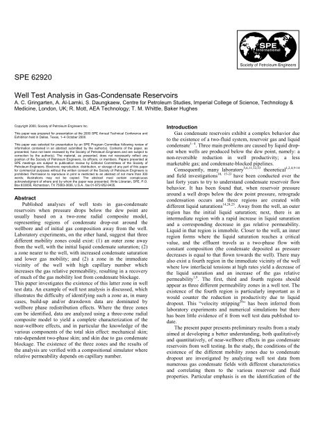
Abstract<br />
Published analyses of well tests <strong>in</strong> gas-condensate<br />
reservoirs when pressure drops below the dew po<strong>in</strong>t are<br />
usually based on a two-zone radial composite model,<br />
represent<strong>in</strong>g regions of condensate drop-out around the<br />
wellbore and of <strong>in</strong>itial gas composition away from the well.<br />
Laboratory experiments, on the other hand, suggest that three<br />
different mobility zones could exist: (1) an outer zone away<br />
from the well, with the <strong>in</strong>itial liquid condensate saturation; (2)<br />
a zone nearer to the well, with <strong>in</strong>creased condensate saturation<br />
and lower gas mobility; and (2) a zone <strong>in</strong> the immediate<br />
vic<strong>in</strong>ity of the well with high capillary number which<br />
<strong>in</strong>creases the gas relative permeability, result<strong>in</strong>g <strong>in</strong> a recovery<br />
of much of the gas mobility lost from condensate blockage.<br />
This paper <strong>in</strong>vestigates the existence of this latter zone <strong>in</strong> well<br />
test data. An example of well test analysis is discussed, which<br />
illustrates the difficulty of identify<strong>in</strong>g such a zone as, <strong>in</strong> many<br />
cases, build-up and/or drawdown data are dom<strong>in</strong>ated by<br />
wellbore phase redistribution effects. Where the three zones<br />
can be identified, data are analyzed us<strong>in</strong>g a three-zone radial<br />
composite model to yield a complete characterization of the<br />
near-wellbore effects, and <strong>in</strong> particular the knowledge of the<br />
various components of the total sk<strong>in</strong> effect: mechanical sk<strong>in</strong>;<br />
rate-dependent two-phase sk<strong>in</strong>; and sk<strong>in</strong> due to gas condensate<br />
blockage. The existence of the three zones and the results of<br />
the analysis are verified with a compositional simulator where<br />
relative permeability depends on capillary number.<br />
Introduction<br />
<strong>Gas</strong> condensate reservoirs exhibit a complex behavior due<br />
to the existence of a two-fluid system, reservoir gas and liquid<br />
condensate 1- 4 . Three ma<strong>in</strong> problems are caused by liquid dropout<br />
when wells are produced below the dew po<strong>in</strong>t, namely: a<br />
non-reversible reduction <strong>in</strong> well productivity; a less<br />
marketable gas; and condensate-blocked pipel<strong>in</strong>es.<br />
Consequently, many laboratory 5,6,11,12,33 theoretical 1,2,4,9-14<br />
and field <strong>in</strong>vestigations 10, 15-23 have been conducted over the<br />
last forty years to try to understand condensate reservoir flow<br />
behavior. It has been found that, when reservoir pressure<br />
around a well drops below the dew po<strong>in</strong>t pressure, retrograde<br />
condensation occurs and three regions are created with<br />
different liquid saturations 14,24,25 . Away from the well, an outer<br />
region has the <strong>in</strong>itial liquid saturation; next, there is an<br />
<strong>in</strong>termediate region with a rapid <strong>in</strong>crease <strong>in</strong> liquid saturation<br />
and a correspond<strong>in</strong>g decrease <strong>in</strong> gas relative permeability.<br />
Liquid <strong>in</strong> that region is immobile. Closer to the well, an <strong>in</strong>ner<br />
region forms where the liquid saturation reaches a critical<br />
value, and the effluent travels as a two-phase flow with<br />
constant composition (the condensate deposited as pressure<br />
decreases is equal to that flown towards the well). There may<br />
also exist a fourth region <strong>in</strong> the immediate vic<strong>in</strong>ity of the well<br />
where low <strong>in</strong>terfacial tensions at high rates yield a decrease of<br />
the liquid saturation and an <strong>in</strong>crease of the gas relative<br />
permeability 1,9 . The first, third and fourth regions should<br />
appear as three different permeability zones <strong>in</strong> a well test. The<br />
existence of the fourth region is particularly important as it<br />
would counter the reduction <strong>in</strong> productivity due to liquid<br />
dropout. This “velocity stripp<strong>in</strong>g 26 ” has been <strong>in</strong>ferred from<br />
laboratory experiments and numerical simulations but there<br />
has been little evidence of it from well test data published todate.<br />
The present paper presents prelim<strong>in</strong>ary results from a study<br />
aimed at develop<strong>in</strong>g a better understand<strong>in</strong>g, both qualitatively<br />
and quantitatively, of near-wellbore effects <strong>in</strong> gas condensate<br />
reservoirs from well test<strong>in</strong>g. In the study, the conditions of the<br />
existence of the different mobility zones due to condensate<br />
dropout are <strong>in</strong>vestigated by analyz<strong>in</strong>g well test data from<br />
numerous gas condensate fields with different characteristics<br />
and correlat<strong>in</strong>g them to the various reservoir and fluid<br />
properties. Particular emphasis is on the identification of the
2 A C. GRINGARTEN, A. AL-LAMKI, S. DAUNGKAEW, R. MOTT, T. M. WHITTLE SPE 62920<br />
enhanced gas relative permeability region around the well, as<br />
it rema<strong>in</strong>s a key uncerta<strong>in</strong>ty <strong>in</strong> well deliverability forecast<strong>in</strong>g 1,<br />
10, 23 . The overall objective of the study is to develop new<br />
methods for predict<strong>in</strong>g well productivity <strong>in</strong> gas condensate<br />
reservoirs.<br />
Previous work<br />
There are relatively few publications deal<strong>in</strong>g with well<br />
test<strong>in</strong>g <strong>in</strong> gas condensate reservoirs 1, 10, 11, 15, 17, 19, 21 . Published<br />
<strong>in</strong>terpretations are performed ma<strong>in</strong>ly on build-up data, because<br />
drawdown data are usually affected by flow rate fluctuations,<br />
and <strong>in</strong> the particular case of gas condensate wells, by noise<br />
due to condensate unload<strong>in</strong>g <strong>in</strong> the wellbore. Analyses use<br />
pressure 1, 12, 17 , s<strong>in</strong>gle-phase pseudo-pressure 11, 12, 21 or twophase<br />
pseudo-pressures 10, 12, 19 . The latter, which require good<br />
experimental measurements of relative permeability curves<br />
(rare for gas condensate systems) yield homogeneous look<strong>in</strong>g<br />
derivatives and give access to the mechanical sk<strong>in</strong> only.<br />
S<strong>in</strong>gle-phase pseudo-pressure, on the other hand, yield,<br />
often composite-shaped derivatives below the dew po<strong>in</strong>t.<br />
These usually resemble curve (a) <strong>in</strong> Figure 1 and suggest the<br />
existence of two mobility-zones, one <strong>in</strong> the vic<strong>in</strong>ity of the<br />
wellbore with reduced gas effective permeability due to liquid<br />
dropout, and one away from the well, with s<strong>in</strong>gle phase gas<br />
where the reservoir pressure is still above the dew po<strong>in</strong>t.<br />
<strong>Analysis</strong> of such build-up data with a two-region composite<br />
model provides the total sk<strong>in</strong> and a 2-phase (condensate<br />
blockage) sk<strong>in</strong> 19 . The non-Darcy coefficient is often estimated<br />
by match<strong>in</strong>g drawdown or rate data with a simulator which<br />
<strong>in</strong>cludes non-Darcy flow, by adjust<strong>in</strong>g the parameter β of the<br />
Forcheimer equation 1, 10 .<br />
There has been no published well test data exhibit<strong>in</strong>g a<br />
region of <strong>in</strong>creased gas mobility <strong>in</strong> the immediate vic<strong>in</strong>ity of<br />
the wellbore (the fourth region mentioned <strong>in</strong> the <strong>in</strong>troduction)<br />
which should yield a response similar to curve (b) <strong>in</strong> Figure 1.<br />
The only mention of the possible existence of such a zone <strong>in</strong><br />
field data is found <strong>in</strong> Ref. 20, where the authors had to<br />
<strong>in</strong>corporate liquid velocity stripp<strong>in</strong>g <strong>in</strong> their simulator to<br />
match DST drawdown data from the Britannia field.<br />
Simulation studies<br />
Before proceed<strong>in</strong>g with the analysis of field data, a number<br />
of simulations were performed with a compositional simulator<br />
(techSIM from AEA Technology), <strong>in</strong> order to verify the<br />
conditions of the existence of the three mobility zones<br />
described above and to develop an understand<strong>in</strong>g of the<br />
derivative shapes to be expected <strong>in</strong> a well test 27 . The simulator<br />
calculates the fluid PVT properties us<strong>in</strong>g an equation-of-state<br />
(EOS) and varies condensate and gas relative permeabilities as<br />
a function of the capillary number, Nc, accord<strong>in</strong>g to<br />
correlations developed by Henderson et al. 28,29 . The simulation<br />
model represents a s<strong>in</strong>gle-well <strong>in</strong> a homogeneous, radial<br />
reservoir of uniform thickness. The reservoir characteristics<br />
are constant and are shown <strong>in</strong> Table 1. The model consists of<br />
40 cells with an outer radius of 11,950 ft to <strong>in</strong>sure that no<br />
boundary effects are seen <strong>in</strong> the simulated well tests. Near the<br />
wellbore, the cells are small to simulate the gas-condensate<br />
near-wellbore behavior accurately. The cell size <strong>in</strong>creases<br />
logarithmically away from the wellbore. The model does not<br />
account for wellbore storage and mechanical sk<strong>in</strong>.<br />
The simulation runs are designed to show the gascondensate<br />
behavior under different production conditions. In<br />
all cases, the <strong>in</strong>itial reservoir pressure is set to just above the<br />
dew po<strong>in</strong>t pressure, so that the liquid-phase condensate forms<br />
at the start of production. An example of a pressure-rate<br />
history for a simulation run is shown <strong>in</strong> Fig. 2. This run<br />
consists of 10 periods of alternat<strong>in</strong>g draw-downs and build-ups<br />
(1DD, 2BU, 3DD, 4BU,…, 9DD, and 10BU). The first<br />
drawdown is extended (100 days) to allow for the condensate<br />
to accumulate <strong>in</strong> the near-well bore region, and the subsequent<br />
periods are ten days long. Variations of this production history<br />
are run with different rates, gas-oil relative permeability<br />
models, and fluid compositions.<br />
Fig. 3 shows how the liquid condensate (So) builds up<br />
around the wellbore dur<strong>in</strong>g the first production period, 1DD,<br />
with and without capillary number (Nc) effects. Capillary<br />
number effects reduce the condensate saturation around the<br />
well and <strong>in</strong> the reservoir. As time <strong>in</strong>crease, the reduction is<br />
greater <strong>in</strong> the immediate vic<strong>in</strong>ity of the wellbore and the<br />
saturation takes a ‘doughnut’ shape around the well. The<br />
correspond<strong>in</strong>g gas relative permeability, shown <strong>in</strong> Figure 4,<br />
exhibits a m<strong>in</strong>imum between 10 and 100 feet <strong>in</strong> our example, a<br />
maximum correspond<strong>in</strong>g to the s<strong>in</strong>gle phase gas away from<br />
the well and an <strong>in</strong>termediate value <strong>in</strong> the few feet around the<br />
well. These are the three mobility regions discussed <strong>in</strong> the<br />
<strong>in</strong>troduction and should yield three stabilizations on the<br />
derivative.<br />
The derivatives of the shut-<strong>in</strong> period, 2BU, follow<strong>in</strong>g the<br />
<strong>in</strong>itial, extended drawdown, are shown <strong>in</strong> Figure 5 <strong>in</strong> terms of<br />
s<strong>in</strong>gle-phase pseudo-pressure, with and without Nc effects. As<br />
expected from the condensate saturation distribution (Figure<br />
3), the early-time mobility is much lower without Nc effects<br />
than with Nc effects. The three stabilizations on the derivative<br />
with Nc effects are not obvious, but should exist as <strong>in</strong>dicated <strong>in</strong><br />
Figure 5, based on the gas relative permeability distribution <strong>in</strong><br />
Figure 4. There should be only two stabilizations without Nc<br />
effects.<br />
Figure 5 is for a lean gas. The same test was simulated for<br />
a rich gas and the gas relative permeability distributions are<br />
compared <strong>in</strong> Figure 6. The rich gas does not show a m<strong>in</strong>imum<br />
and the correspond<strong>in</strong>g derivative should have two<br />
stabilizations only, as illustrated <strong>in</strong> Figure 7.<br />
The simulation study thus confirms that, when capillary<br />
number effects are important, the pressure derivative should<br />
exhibit three stabilizations. In our example, the differences<br />
between the various stabilizations are very small: the<br />
permeability thickness selected was 1000 mD.ft, which seems<br />
to be the limit beyond which well productivity is no longer<br />
affected by condensate deposition 30 . Lower permeabilitythickness<br />
values should yield greater contrast between<br />
stabilization levels.<br />
Impact of wellbore dynamics<br />
When look<strong>in</strong>g at field data, it becomes obvious that one<br />
reason for the lack of well tests show<strong>in</strong>g a zone of <strong>in</strong>creased<br />
gas mobility around the wellbore is that such data are difficult
SPE 62920 WELL TEST ANALYSIS IN GAS-CONDENSATE RESERVOIRS 3<br />
to identify with confidence. When they may exist, they are<br />
also likely to be hidden by wellbore phase redistribution<br />
effects. Phase redistribution occurs when different phases flow<br />
<strong>in</strong> different directions <strong>in</strong> the wellbore. Typical examples are<br />
oil and water, gas and water, gas and liquid condensate, and<br />
oil and gas <strong>in</strong> gas-lifted wells. It creates an <strong>in</strong>crease <strong>in</strong> the<br />
wellbore storage coefficient and may be present <strong>in</strong> drawdowns<br />
or <strong>in</strong> build-up’s. This is different from a phase change, which<br />
creates a decrease <strong>in</strong> the wellbore storage coefficient <strong>in</strong> a<br />
build-up and an <strong>in</strong>crease <strong>in</strong> the drawdown. The impact of<br />
phase change on the pressure behavior is usually limited to<br />
early times whereas an <strong>in</strong>crease <strong>in</strong> wellbore storage due to<br />
phase redistribution may dom<strong>in</strong>ate the test for many hours.<br />
Recogniz<strong>in</strong>g the existence of wellbore phase redistribution<br />
is important because it can create derivative shapes which<br />
could be easily mis<strong>in</strong>terpreted as they are similar to what<br />
would be obta<strong>in</strong>ed with double porosity, partial penetration or<br />
composite behaviors. Typical derivative shapes due to phase<br />
redistribution (whether <strong>in</strong> a drawdown or <strong>in</strong> a build-up) are<br />
shown <strong>in</strong> Figure 8. Curve (5) <strong>in</strong> Figure 8 corresponds to the<br />
denser phase be<strong>in</strong>g re-<strong>in</strong>jected <strong>in</strong>to the formation.<br />
An example of how phase redistribution can affect<br />
multiphase flow pressure behavior and therefore the analysis<br />
of the data is shown <strong>in</strong> Figure 9. Figure 9 is a log-log plot of<br />
rate normalized pressure and pressure derivative for a<br />
drawdown and the follow<strong>in</strong>g build-up <strong>in</strong> a North Sea well<br />
produc<strong>in</strong>g oil and water (<strong>Well</strong> A). Rate normalized means that<br />
the pressure change and the derivative have been divided by<br />
the applicable rate so that the derivatives stabilize at the same<br />
level dur<strong>in</strong>g radial flow <strong>in</strong> all the flow periods. In Figure 9, the<br />
drawdown and build-up derivatives are different at early<br />
times, as the well was open at the surface for the drawdown,<br />
and shut-<strong>in</strong> downhole for the build-up. They also, however,<br />
differ at late times, with different apparent radial flow<br />
stabilizations. Interpretation of production logs run dur<strong>in</strong>g<br />
both drawdown and build-up po<strong>in</strong>ts to reverse water flow <strong>in</strong><br />
the wellbore dur<strong>in</strong>g build-up. This suggests that the build-up is<br />
entirely dom<strong>in</strong>ated by <strong>in</strong>creas<strong>in</strong>g wellbore storage and<br />
therefore is not <strong>in</strong>terpretable. <strong>Analysis</strong> <strong>in</strong> this example has to<br />
be performed on the drawdown.<br />
The same phenomena is often seen <strong>in</strong> gas wells produc<strong>in</strong>g<br />
water. Figure 10 shows the pressure and rate history dur<strong>in</strong>g a<br />
well test <strong>in</strong> a dry gas well <strong>in</strong> Canada (<strong>Well</strong> B). One build-up<br />
and five drawdowns are presented on the rate-normalised loglog<br />
plot of Figure 11. Data <strong>in</strong> Figure 11 are plotted <strong>in</strong> terms of<br />
normalized pseudo-pressure 10 . The drawdown called “Flow<br />
period 2” is at the beg<strong>in</strong>n<strong>in</strong>g of the test, and is followed by the<br />
build-up (Flow period 4). All drawdowns <strong>in</strong> Figure 11 except<br />
the one correspond<strong>in</strong>g to Flow period 15 exhibit similar<br />
shapes (except for differences <strong>in</strong> sk<strong>in</strong> and wellbore storage at<br />
early times) and tend towards the same derivative radial flow<br />
stabilization at late times. The behavior of the build-up (Flow<br />
period 4) and of the drawdown Flow period 15, on the other<br />
hand, are very different. This can be expla<strong>in</strong>ed as follows:<br />
dur<strong>in</strong>g a drawdown, a mixture of gas and water droplets flows<br />
up the well. When the well is shut-<strong>in</strong>, the droplets rema<strong>in</strong><br />
suspended for a little while and then drop down, creat<strong>in</strong>g a<br />
liquid cushion at the bottom of the well which may even be<br />
re<strong>in</strong>jected <strong>in</strong>to the reservoir, by gravity or by expansion of the<br />
gas at the top of the well. This results <strong>in</strong> an <strong>in</strong>crease <strong>in</strong><br />
wellbore storage effects which could dom<strong>in</strong>ate the entire<br />
build-up behavior and render the analysis impossible. This<br />
does not happen <strong>in</strong> drawdowns unless the concentration of<br />
denser fluid <strong>in</strong> the wellbore is such that it cannot be lifted by<br />
the gas to the surface. This would occur <strong>in</strong> drawdowns with<br />
low flow rates, or <strong>in</strong> drawdowns follow<strong>in</strong>g a previous<br />
drawdown at a higher rate, such as Flow period 15. In the<br />
particular example of Figure 11, although the shape of the<br />
build-up resemble that of a composite behavior, the build-up is<br />
entirely dom<strong>in</strong>ated by wellbore phase redistribution and not<br />
<strong>in</strong>terpretable: analysis with a composite model would<br />
overestimate the gas mobility by a factor 3. Here aga<strong>in</strong>,<br />
analysis must be performed on the drawdowns (Flow period<br />
2).<br />
Phase redistribution is also present <strong>in</strong> drawdowns and<br />
build-up’s from gas condensate wells. Figure 12 is a ratenormalized<br />
log-log plot of drawdown data (Flow periods 7,<br />
14, 15 and 18) for a North Sea lean gas condensate well (<strong>Well</strong><br />
C). Pressures and derivatives are expressed <strong>in</strong> terms of s<strong>in</strong>glephase<br />
normalized pseudo-pressure 10 . Drawdown data are<br />
obviously dom<strong>in</strong>ated by <strong>in</strong>creas<strong>in</strong>g wellbore storage. As<br />
should be expected, this effect seems more pronounced and<br />
appears to last longer for low flow rates (Flow periods 14, 7<br />
and 15). The higher rate drawdown Flow period 18 seems less<br />
affected compared to the other drawdowns. Its derivative is<br />
similar to that for the build-up’s, Flow periods 8, 18 and 21,<br />
shown <strong>in</strong> Figure 13. Close <strong>in</strong>spection of the build-up’s shows<br />
that they also are affected by phase redistribution <strong>in</strong> the period<br />
1 to 10 hours, so it is possible that the drawdown Flow period<br />
17 is affected as well. This has to be taken <strong>in</strong>to account when<br />
perform<strong>in</strong>g the analysis.<br />
Early time well test behavior of gas condensate wells<br />
One of the objective of our study is to confirm the<br />
existence of “velocity stripp<strong>in</strong>g” <strong>in</strong> gas condensate wells from<br />
well test data. This refers to an enhanced gas mobility zone at<br />
high rates <strong>in</strong> the immediate vic<strong>in</strong>ity of the wellbore due to<br />
high capillary numbers. We are therefore look<strong>in</strong>g for<br />
derivatives exhibit<strong>in</strong>g a three-region composite behavior,<br />
similar to curve (b) <strong>in</strong> Figure 1. As discussed <strong>in</strong> the previous<br />
section, the challenge is to avoid data affected by wellbore<br />
phase redistribution.<br />
Data for <strong>Well</strong> C <strong>in</strong> Figure 13 seem to show a three-region<br />
composite behavior and therefore could be <strong>in</strong>terpreted to<br />
quantify the three mobility zones def<strong>in</strong>ed <strong>in</strong> the <strong>in</strong>troduction.<br />
The analysis is best performed on the drawdown data Flow<br />
period 17, as it is the longest period of the test and shows more<br />
of the various composite features. The f<strong>in</strong>al derivative<br />
stabilization, correspond<strong>in</strong>g to the mobility of the gas with the<br />
<strong>in</strong>itial condensate saturation, is easy to locate, slightly below<br />
the last data po<strong>in</strong>ts after 100 hours. The derivative stabilization<br />
correspond<strong>in</strong>g to the <strong>in</strong>creased condensate saturation is<br />
equally easy to locate, at the level of the derivative hump<br />
around 10 hours. The location of the derivative stabilization<br />
correspond<strong>in</strong>g to the enhanced gas mobility, on the other hand,<br />
is much more difficult to f<strong>in</strong>d. It must be between the other
4 A C. GRINGARTEN, A. AL-LAMKI, S. DAUNGKAEW, R. MOTT, T. M. WHITTLE SPE 62920<br />
two, and therefore cannot correspond to the m<strong>in</strong>imum at 1<br />
hour. This m<strong>in</strong>imum must correspond to wellbore phase<br />
redistribution effects, as suggested by the shapes of the buildup’s<br />
<strong>in</strong> Figure 14. There is therefore a significant uncerta<strong>in</strong>ty<br />
<strong>in</strong> this particular example.<br />
When a choice has been made for the first stabilization, the<br />
analysis can be performed with a three region composite<br />
model 31 (Figure 15), based on a solution by Satman, et al. 32 .<br />
The log-log match with such a model is shown <strong>in</strong> Figure 16:<br />
(1) represents the three-region composite model with no<br />
wellbore storage and sk<strong>in</strong>; (2) is the same solution for constant<br />
wellbore storage; and (3) is the chang<strong>in</strong>g wellbore storage<br />
solution. The latter also provides a good match on the<br />
superposition plot and for the simulation of the entire test. The<br />
<strong>in</strong>ternal and external radii of the condensate “doughnut” are<br />
100 and 500 feet, respectively.<br />
Another example of the possible existence of three<br />
derivative stabilizations is shown <strong>in</strong> Figure 17. The data are<br />
from <strong>Well</strong> D, another North Sea lean gas condensate reservoir.<br />
They can be <strong>in</strong>terpreted with either a two-region or a threeregion<br />
composite model. Both analyses give parameter values<br />
which are reasonable. The complete analysis is shown <strong>in</strong><br />
Figures 18 to 20 (respectively, Horner match, simulation, and<br />
sk<strong>in</strong> versus rate plots). It yields all the components of the sk<strong>in</strong><br />
factor.<br />
Discussion and Conclusions<br />
This paper presents the prelim<strong>in</strong>ary results of a systematic<br />
study of well tests <strong>in</strong> gas condensate reservoirs. One of the<br />
primary objectives is to <strong>in</strong>vestigate the conditions of the<br />
existence of the different mobility zones due to condensate<br />
dropout and velocity stripp<strong>in</strong>g.<br />
It was found that phase redistribution is a major problem <strong>in</strong><br />
analyz<strong>in</strong>g the data. It not only reduces the amount of data<br />
available for analysis, but may also create drawdown or buildup<br />
shapes that can easily be mis<strong>in</strong>terpreted for reservoir<br />
behaviors.<br />
Examples have been shown that seem to exhibit three<br />
stabilizations on the derivative, correspond<strong>in</strong>g to three<br />
mobility zones: (1) an outer zone away from the well, with<br />
the <strong>in</strong>itial liquid condensate saturation; (2) a zone nearer to the<br />
well, with <strong>in</strong>creased condensate saturation and lower gas<br />
mobility; and (2) a zone <strong>in</strong> the immediate vic<strong>in</strong>ity of the well<br />
with high capillary number which <strong>in</strong>creases the gas relative<br />
permeability, result<strong>in</strong>g <strong>in</strong> a recovery of much of the gas<br />
mobility lost from condensate blockage.<br />
These results have to be considered with caution, however,<br />
until more systematic evidence of such behavior becomes<br />
available.<br />
References<br />
1. Economides, M.J, Dehghani, K., Ogbe, D.O., and<br />
Ostermann, R.D.:” Hysteresis Effects for <strong>Gas</strong> <strong>Condensate</strong><br />
<strong>Well</strong>s Undergo<strong>in</strong>g Build-up <strong>Test</strong>s below the Dew Po<strong>in</strong>t<br />
Pressure”, SPE paper 16748, presented at the 62nd Annual<br />
Technical Conference and Exhibition of the Society of<br />
Petroleum Eng<strong>in</strong>eers, Dallas, TX September 27-30, 1987.<br />
2. Bloom, S. M. P., and Hagoort, J.:” The Comb<strong>in</strong>e effect of<br />
Near-Critical Relative Permeability and Non-Darcy Flow<br />
on <strong>Well</strong> Impairment by <strong>Condensate</strong> Drop-Out,” paper SPE<br />
39976 presented at the 1998 SPE <strong>Gas</strong> Technology<br />
Symposium, Canada, 15-18 March, 1998.<br />
3. Yu X., Lei, S., Liangtian, S., and Shilun, L.: “A New<br />
Method for Predict<strong>in</strong>g the Law of Unsteady Flow Through<br />
Porous Medium on <strong>Gas</strong> <strong>Condensate</strong> <strong>Well</strong>,” paper<br />
SPE35649 presented at SPE Program Conference, Canada,<br />
28 Apr- 1 May, 1996.<br />
4. Gondou<strong>in</strong>, M., Iffly, R. and Husson, J.:”An Attempt to<br />
Predict the Time Dependence of <strong>Well</strong> deliverability <strong>in</strong><br />
<strong>Gas</strong>-<strong>Condensate</strong> Fields,” SPEJ (June 1967) pp112-124.<br />
5. Coles, M. E., Hartman, H. J.: “Non-Darcy Measurements<br />
<strong>in</strong> Dry Core and Effect of Immobile Liquid,” paper SPE<br />
39977 presented at the 1998 SPE <strong>Gas</strong> Technology<br />
Symposium, Canada, 15-18 March, 1998.<br />
6. Barnum, R. S., Br<strong>in</strong>kman, F. P., Richardson, T. W., and<br />
Spillette, A. G.: “ <strong>Gas</strong> <strong>Condensate</strong> Reservoir Behaviour:<br />
Productivity and Recovery Reduction Due to<br />
Condensation,” paper SPE 30767 presented at the SPE<br />
Annual Technical Conference and Exhibition, Texas, 22-<br />
25 October, 1995.<br />
7. Danesh, A., Tehrani, D. H., Henderson, G. D., Al-Kharusi,<br />
B., Jamiolahmadi, M., Ireland, S., and Thomson, G.:” <strong>Gas</strong><br />
<strong>Condensate</strong> Recovery Studies,” paper presented at<br />
<strong>Condensate</strong> Reservoir Studies, London, 17 Oct., 1984.<br />
8. Mott, R.: “ <strong>Gas</strong> <strong>Condensate</strong> <strong>Well</strong> Productivity,” paper<br />
presented at <strong>Condensate</strong> Reservoir Studies, London, 17<br />
Oct., 1984.<br />
9. Fussell, D.D.:”S<strong>in</strong>gle-<strong>Well</strong> Performance Predictions for<br />
<strong>Gas</strong> <strong>Condensate</strong> <strong>Reservoirs</strong>”, SPE 4072, July 1973.<br />
10. Saleh, A.M. and Stewart, G.:” Interpretation of <strong>Gas</strong><br />
<strong>Condensate</strong> <strong>Well</strong> <strong>Test</strong>s With Field Examples”, SPE paper<br />
24719, presented at the 67th Annual Technical Conference<br />
and Exhibition of the Society of Petroleum Eng<strong>in</strong>eers held<br />
<strong>in</strong> Wash<strong>in</strong>gton, DC, October 4-7, 1992.<br />
11. Thompson, L.G., Niu, J<strong>in</strong>-Guo and Reynolds, A.C.:” <strong>Well</strong><br />
<strong>Test</strong><strong>in</strong>g for <strong>Gas</strong> <strong>Condensate</strong> <strong>Reservoirs</strong>,” SPE paper 25371<br />
presented at the SPE Asia Pacific Oil and <strong>Gas</strong> Conference<br />
and Exhibition held <strong>in</strong> S<strong>in</strong>gapore, 8-10 February 1993.<br />
12. Hernandez-G., Hector, Samaniego V., Fernando,<br />
Camacho-V., R.G. :” <strong>Gas</strong> <strong>Condensate</strong> <strong>Well</strong> <strong>Test</strong><strong>in</strong>g Under<br />
the Influence of High-Velocity Flow “, SPE paper 26666<br />
presented at the 68th Annual Technical Conference and<br />
Exhibition of the Society of Petroleum Eng<strong>in</strong>eers,<br />
Houston, Texas, 3-6 October 1993.<br />
13. Kniazeff, V.J., and Naville, S.A.: “ Two-Phase Flow of<br />
Volatile Hydrocarbons”, SPEJ (March 1965), 37.<br />
14. Favang, Ø., Whitson, C. H.: “Modell<strong>in</strong>g <strong>Gas</strong> <strong>Condensate</strong><br />
<strong>Well</strong> Deliverability,” paper SPE 30714 presented at the<br />
SPE Annual Technical Conference and Exhibition, Texas,<br />
22-25 October, 1995.<br />
15. Behrenbruch, P. and Kozma, G.;” Interpretation of Results<br />
From <strong>Well</strong> <strong>Test</strong><strong>in</strong>g <strong>Gas</strong>-<strong>Condensate</strong> <strong>Reservoirs</strong>:
SPE 62920 WELL TEST ANALYSIS IN GAS-CONDENSATE RESERVOIRS 5<br />
Comparison of Theory and Field Cases,” SPE paper<br />
13185, presented at the 59th Annual Technical Conference<br />
and Exhibition held <strong>in</strong> Houston, Texas, September 16-19,<br />
1984.<br />
16. Economides, Michael J., Cikes, Mar<strong>in</strong>, Pforter, Harry,<br />
Udick, Thomas H. and Uroda, Pavle:”The Stimulation of a<br />
Tight, Very-High-Temperature <strong>Gas</strong>-<strong>Condensate</strong> <strong>Well</strong>”,<br />
SPE paper 15239, March 1989<br />
17. Chu, W-C, and Shank, G.D.:” A New Model for a<br />
Fractured <strong>Well</strong> <strong>in</strong> a Radial, Composite Reservoir,” SPE<br />
paper 20579, presented at the 65th Annual Technical<br />
Conference and Exhibition of the Society of Petroleum<br />
Eng<strong>in</strong>eers, New Orleans, LA, September 23-26, 1990.<br />
18. S∅gnesand, S.:” Long-Term <strong>Test</strong><strong>in</strong>g of Vertically<br />
Fractured <strong>Gas</strong> <strong>Condensate</strong> <strong>Well</strong>s”, SPE paper 21704,<br />
presented at the Production Operations Symposium,<br />
Oklahoma City, Oklahoma, April 7-9, 1991.<br />
19. Raghavan, R., Chu, W and Jones, J.:”Practical<br />
considerations <strong>in</strong> the <strong>Analysis</strong> of gas condensate well test”,<br />
SPE paper 30576, presented at the 70th Annual Technical<br />
Conference and Exhibition of the Society of Petroleum<br />
Eng<strong>in</strong>eers, Dallas, Texas, 22-25 October 1995.<br />
20. Diamond, P.H., Pressney, R.A., Snyder, D.E. and<br />
Seligman, P.R.:”Probabilistic prediction of well<br />
performance <strong>in</strong> a gas condensate reservoir”, SPE paper<br />
36894 presented at the 1996 SPE European Petroleum<br />
Conference, Milan, Italy, 22-24 October 1996.<br />
21. Marhaendrajana, T., Kaczorowski, N. J., Blas<strong>in</strong>game, T.<br />
A.: “<strong>Analysis</strong> and Interpretation of <strong>Well</strong> <strong>Test</strong> Performance<br />
at Arun Field, Indonesia,” paper SPE56487 presented at<br />
the 1999 SPE annual Conference and Exhibition, Texas, 3-<br />
6 October, 1999.<br />
22. Novosad, Z.: 2 Compositional and Phase Changes <strong>in</strong><br />
<strong>Test</strong><strong>in</strong>g and Produc<strong>in</strong>g Retrograde <strong>Gas</strong> <strong>Well</strong>s,” paper SPE<br />
35645 presented at the <strong>Gas</strong> Technology Conference,<br />
Canada, 28 Apr. – 1 Mar., 1996.<br />
23. Afidick, D., Kaczorowski, N. J., and Bette, S.: “Production<br />
Performance of a Retrograde <strong>Gas</strong> Reservoir: A Case Study<br />
of Arun Field,” paper SPE 28749 presented at the SPE<br />
Asia Pacific Oil and <strong>Gas</strong> Conference, Australia, 7-10<br />
November, 1994.<br />
24. Ali, J. K., McGauley, P. J., and Wilson, C. J.: “<br />
Experimental Studies and Modell<strong>in</strong>g of <strong>Gas</strong> <strong>Condensate</strong><br />
Flow Near the <strong>Well</strong>bore,” paper SPE 39053 presented at<br />
the fifth Lat<strong>in</strong> American and Carribbean Petroleum<br />
Eng<strong>in</strong>eer<strong>in</strong>g Conference and Exhibition, Brazil, 30 August<br />
- 3 September, 1997.<br />
25. Kalaydjian, F. J-M., Bourbiaux, B. J., Lambard, J-M.,<br />
1996, “ Predict<strong>in</strong>g <strong>Gas</strong>-<strong>Condensate</strong> Reservoir<br />
Performance: How flow parameters are altered when<br />
approach<strong>in</strong>g Production <strong>Well</strong>s.”, paper SPE 36715<br />
presented at the 1996 SPE Annual Conference and<br />
Exhibition, Colorado, 6-9 October, 1996.<br />
26. Mott, R., Cable, A., and Spear<strong>in</strong>g, M.: “ A New Method of<br />
Measur<strong>in</strong>g Relative Permeabilities for Calculat<strong>in</strong>g <strong>Gas</strong>-<br />
<strong>Condensate</strong> <strong>Well</strong> Deliverability,” paper SPE 56484<br />
presented at the 1999 SPE Annual Conference and<br />
Exhibition, Texas, 3-6 Oct., 1999.<br />
27. Al-Lamki, A.:” The effects of rate-dependent relative<br />
permeabilities on the <strong>in</strong>terpretation of gas condensate well<br />
tests”, MSc Individual Project Report, Centre for<br />
Petroleum Studies, Imperial College for Science,<br />
Technology and Medic<strong>in</strong>e, London, UK, Sept. 1999.<br />
28. Henderson, G.D., Danesh, A., Tehrani, D.H., Al-Shaidi, S.,<br />
and Peden, J.M., “Measurement and Correlation of <strong>Gas</strong>condensate<br />
Relative Permeability by the Steady-State<br />
Method”, SPE 30770, SPE Annual Technical Conference<br />
& Exhibition, Dallas, October 1995.<br />
29. Henderson, G.D., Danesh, A., Tehrani, D.H., and Peden,<br />
J.M., “The Effect of Velocity and Interfacial Tension on<br />
Relative Permeability of <strong>Gas</strong>-condensate Fluids <strong>in</strong> the <strong>Well</strong><br />
Bore Region”, Journal of Petroleum, Science &<br />
Eng<strong>in</strong>eer<strong>in</strong>g v. 17, pp 265-273, 1997.<br />
30. Bauman, R.S., Br<strong>in</strong>kman, F.P., Richardson, T.W.,<br />
Spillette, A.G., “<strong>Gas</strong> <strong>Condensate</strong> Reservoir Behaviour:<br />
Productivity and Recovery Restriction Due to<br />
Condensation”, SPE 30767, SPE Annual Technical<br />
Conference & Exhibition, Dallas, October 1995.<br />
31. Daungkaew, S.:” <strong>Well</strong>-<strong>Test</strong> <strong>Analysis</strong> us<strong>in</strong>g a Triple Radial<br />
Composite Model and its Application to <strong>Gas</strong> <strong>Condensate</strong><br />
<strong>Reservoirs</strong>”, MSc Individual Project Report, Centre for<br />
Petroleum Studies, Imperial College for Science,<br />
Technology and Medic<strong>in</strong>e, London, UK, Sept. 1998.<br />
32. Satman, A., Eggenschwiler, M. and Ramey., Henry J.,<br />
Jr:”Interpretation of Injection <strong>Well</strong> Pressure Transient Data<br />
<strong>in</strong> Thermal Oil Recovery” , paper SPE 8908 presented at<br />
the 50th Annual California Regional Meet<strong>in</strong>g of the<br />
Society of Petroleum Eng<strong>in</strong>eers of AIME , Log Angeles,<br />
California, April 9-11, 1980.<br />
33. W. Boom, K. Wit, A.M. Schulte, S. Oedai, J.P.W.<br />
Zeelenberg and J.G. Maas:”Experimental Evidence for<br />
Improved <strong>Condensate</strong> Mobility at Near-wellbore Flow<br />
Conditions,” SPE paper 30766, presented at the 70th<br />
Annual Technical Conference and Exhibition of the<br />
Society of Petroleum Eng<strong>in</strong>eers, Dallas, TX, U.S.A., 22-25<br />
October, 1995.
6 A C. GRINGARTEN, A. AL-LAMKI, S. DAUNGKAEW, R. MOTT, T. M. WHITTLE SPE 62920<br />
m n (p) change and derivative (psi)<br />
10 3<br />
10 2<br />
10<br />
(b)<br />
(a)<br />
<strong>Gas</strong> with lower condensate<br />
saturation (stripp<strong>in</strong>g)<br />
10-3 10-2 10-1 1 10 102 103 1<br />
Elapsed time (hours)<br />
High condensate<br />
Saturation (liquid drop-out)<br />
<strong>Gas</strong> with <strong>in</strong>itial<br />
<strong>Condensate</strong> saturation<br />
Fig. 1: Schematic of pressure and derivative composite behavior:<br />
(a) two-region composite; (3) three-region composite<br />
Pressure (psia)<br />
4000<br />
3500<br />
3000<br />
2500<br />
2000<br />
1500<br />
1000<br />
500<br />
0<br />
1DD 2BU 3DD 4BU 5DD 6BU 7DD 8BU 9DD 10B<br />
Pressure<br />
Rate (mmscf/d)<br />
70 90 110 130 150 170 190<br />
Time (days)<br />
Fig. 2: Rate & Pressure History Example for the Simulation Runs.<br />
So<br />
0.3<br />
0.25<br />
0.2<br />
0.15<br />
0.1<br />
0.05<br />
with Nc<br />
0.1day<br />
without Nc<br />
100days<br />
100days<br />
0.1day<br />
0<br />
0.1 1 10 100 1000 10000<br />
Radial Distance (ft)<br />
Change with time<br />
35<br />
30<br />
25<br />
20<br />
15<br />
10<br />
5<br />
0<br />
Rate (mmscf/d)<br />
0.1days<br />
1day<br />
10days<br />
100days<br />
Fig. 3: Saturation distribution <strong>in</strong> the reservoir dur<strong>in</strong>g the first<br />
extended drawdown<br />
Relative Permeability, k rg<br />
1<br />
0.94<br />
0.88<br />
0.82<br />
Reduction with time<br />
0.1 day<br />
1 day<br />
10 days<br />
100 days<br />
0.1 1 10 100 1000 10000<br />
Radial Distance (ft)<br />
Fig. 4: <strong>Gas</strong> relative permeability distribution <strong>in</strong> the reservoir<br />
dur<strong>in</strong>g the first extended drawdown<br />
m(p) change (10 -6 psi 2 /cp)<br />
10 3<br />
10 2<br />
10<br />
With N c<br />
Without N c<br />
10-4 10-3 10-2 10-1 1<br />
1 10<br />
Elapsed time (days)<br />
Fig. 5: Log-log pressure derivatives for the build-up follow<strong>in</strong>g the<br />
first extended drawdown<br />
krg<br />
1<br />
0.9<br />
0.8<br />
0.7<br />
0.6<br />
0.5<br />
0.4<br />
0.3<br />
0.2<br />
0.1<br />
0<br />
Lean gas<br />
Rich gas<br />
0.1 1 10 100 1000 10000<br />
Radial Distance (ft)<br />
Fig. 6: <strong>Gas</strong> relative permeability distribution for lean and rich<br />
gases dur<strong>in</strong>g the first extended drawdown
SPE 62920 WELL TEST ANALYSIS IN GAS-CONDENSATE RESERVOIRS 7<br />
m(p) change (10 -6 psi 2 /cp) 102<br />
RICH GAS<br />
LEAN GAS<br />
10-4 10-3 10-2 10-1 10<br />
1 10<br />
Elapsed time (days)<br />
Fig. 7: Log-log pressure derivatives for the build-up follow<strong>in</strong>g the<br />
first extended drawdown<br />
Normalized Pseudo-Pressure Derivative ( psi)<br />
10 4<br />
10 3<br />
10 2<br />
10<br />
Re<strong>in</strong>jection of<br />
condensate cushion<br />
Elapsed time, ∆t ( hours)<br />
Radial Flow<br />
Stabilisation<br />
10-3 10-2 10-1 1 10 102 103 1<br />
Fig. 8: Log-log derivative plots, <strong>in</strong>creas<strong>in</strong>g wellbore storage due<br />
to phase redistribution <strong>in</strong> the wellbore<br />
Rate normalized pressure change and derivative (kPa)<br />
10 4<br />
10 3<br />
10 2<br />
Drawdown<br />
(1)<br />
(2)<br />
(3)<br />
(4)<br />
(5)<br />
Build-up<br />
10-3 10-3 10-2 10-1 1 10 102 10<br />
Elapsed time (hours)<br />
Radial Flow Stabilization<br />
Fig. 9: Log-log plot, oil/water <strong>Well</strong> A, show<strong>in</strong>g <strong>in</strong>creas<strong>in</strong>g wellbore<br />
storage due to phase redistribution <strong>in</strong> the wellbore dur<strong>in</strong>g buildup<br />
Pressure (psia)<br />
4000<br />
3000<br />
2000<br />
Flow Periods:<br />
(1) (2) (3)<br />
(4)<br />
(9) (11) (12) (14) (15)<br />
1000<br />
20 40 60 80 100<br />
Time from the start of the test (hours)<br />
Fig. 10: Pressure and rate test history, dry gas <strong>Well</strong> B<br />
Rate normalized m n (p) change and derivative (psi)<br />
10 4<br />
10 3<br />
10 2<br />
Flow<br />
Period<br />
7<br />
9<br />
2<br />
11<br />
15<br />
4<br />
Type<br />
Dd<br />
Dd<br />
Dd<br />
Dd<br />
Dd<br />
Bu<br />
Current (Drawdown) or<br />
Previous (Build-up) Rate<br />
20,000 Mscf/D<br />
28,000<br />
31,400<br />
32,600<br />
13,000<br />
31,400<br />
9<br />
7<br />
40000<br />
30000<br />
20000<br />
10000<br />
10-3 10-2 10-1 1 10 102 10<br />
Elapsed time (hours)<br />
2<br />
15<br />
11<br />
0<br />
4<br />
Radial flow<br />
stabilization<br />
Fig. 11: Log-log plot, dry gas <strong>Well</strong> B, show<strong>in</strong>g <strong>in</strong>creas<strong>in</strong>g wellbore<br />
storage due to phase redistribution <strong>in</strong> the wellbore dur<strong>in</strong>g buildup<br />
and decreas<strong>in</strong>g rate drawdown<br />
Rate normalized m n(p) change and derivative (psi)<br />
10 3<br />
10 2<br />
10<br />
FP 7 (DD 45 MScf/D)<br />
FP 15 (DD 47 MScf/D)<br />
FP 14 (DD 38 MScf/D)<br />
FP 18 (DD 57.5 MScf/D)<br />
1<br />
10-3 10-2 10-1 1 10 102 103 Elapsed time (hours)<br />
Fig. 12: Log-log plot, gas condensate <strong>Well</strong> C, show<strong>in</strong>g <strong>in</strong>creas<strong>in</strong>g<br />
wellbore storage due to phase redistribution <strong>in</strong> the wellbore<br />
dur<strong>in</strong>g low rate drawdowns<br />
Flow Rate (Mscf/D)
8 A C. GRINGARTEN, A. AL-LAMKI, S. DAUNGKAEW, R. MOTT, T. M. WHITTLE SPE 62920<br />
Rate normalized m n(p) change and derivative (psi)<br />
10 3<br />
10 2<br />
10<br />
FP 21 BU (DD 38 MScf/D)<br />
1<br />
10-3 10-2 10-1 1 10 102 103 Elapsed time (hours)<br />
FP 8 BU (DD 45 MScf/D)<br />
FP 18 BU (DD 57.5 MScf/D)<br />
FP 17 (DD 57.5 MScf/D)<br />
Fig. 13: Log-log plot, gas condensate <strong>Well</strong> C, show<strong>in</strong>g little phase<br />
redistribution <strong>in</strong> the wellbore dur<strong>in</strong>g build-up’s and high rate<br />
drawdown<br />
Rate normalized m n (p) change and derivative (psi)<br />
10 3<br />
10 2<br />
10<br />
?<br />
<strong>Gas</strong> with lower<br />
condensate<br />
saturation (stripp<strong>in</strong>g)<br />
High condensate<br />
Saturation (liquid drop-out)<br />
1<br />
10-3 10-2 10-1 1 10 102 103 Elapsed time (hours)<br />
Fig. 14: Log-log Diagnostic Plot for <strong>Well</strong> C<br />
<strong>Gas</strong> with lower<br />
condensate<br />
saturation (stripp<strong>in</strong>g)<br />
(kh/µ) 1 , (φµc t h) 1<br />
High condensate<br />
Saturation (liquid drop-out)<br />
(kh/µ) 2 , (φµc t h) 2<br />
Fig. 15: Schematic of three-region composite model<br />
r 1<br />
r 2<br />
<strong>Gas</strong> with <strong>in</strong>itial<br />
<strong>Condensate</strong><br />
Saturation<br />
<strong>Gas</strong> with <strong>in</strong>itial<br />
<strong>Condensate</strong> saturation<br />
(kh/µ) 3 , (φµc t h) 3<br />
Rate normalized m n(p) change and derivative (psi)<br />
10 3<br />
10 2<br />
10<br />
(1)<br />
FP 16 (DD 57.5 MScf/D)<br />
(3) (2)<br />
<strong>Gas</strong> with lower<br />
condensate<br />
saturation (stripp<strong>in</strong>g)<br />
High condensate<br />
Saturation (liquid drop-out)<br />
1<br />
10-3 10-2 10-1 1 10 102 103 Elapsed time (hours)<br />
<strong>Gas</strong> with <strong>in</strong>itial<br />
<strong>Condensate</strong><br />
Saturation<br />
Fig. 16: <strong>Analysis</strong> of gas condensate <strong>Well</strong> C with the three-region<br />
composite model (Log-log Match)<br />
m n (p) change and derivative (psi)<br />
10 4<br />
10 3<br />
10 2<br />
10<br />
3-Region composite:<br />
r 1 = 33 ft; (kh/µ) 1/2 =2.7 ; (φµc t ) 1/2 =1.9<br />
r 2 =322 ft; (kh/µ) 2/3 =0.32; (φµc t ) 2/3 =0.33<br />
2-Region composite: r 1 =365 ft; (kh/µ) 1/2 =0.24; (φµc t ) 1/2 =0.32<br />
10 -2 10 -1 1 10 10 2 10 3<br />
Elapsed time (hours)<br />
Fig. 17: <strong>Analysis</strong> of gas condensate <strong>Well</strong> D with the three-region<br />
composite model (Log-log Match)<br />
Normalised Pseudo Pressure (psia)<br />
8000<br />
7000<br />
6000<br />
5000<br />
4000<br />
3000<br />
2-Region composite<br />
2000 3-Region composite<br />
1000<br />
0 10000 20000 30000 40000<br />
Superposition Function (Mscf/D)<br />
Fig. 18: <strong>Analysis</strong> of gas condensate <strong>Well</strong> D with the three-region<br />
composite model (Horner Match)
SPE62920 WELL TEST ANALYSIS IN GAS-CODENSATE RESERVOIRS 9<br />
Pressure (psia)<br />
6000<br />
5000<br />
4000<br />
3000<br />
2000<br />
1000<br />
100 110 120 130 140 150 160 170<br />
Elapsed time (hrs)<br />
Fig. 19: <strong>Analysis</strong> of gas condensate <strong>Well</strong> D with the three-region<br />
composite model (Horner Match)<br />
Sk<strong>in</strong><br />
37.0<br />
36.6<br />
36.2<br />
35.8<br />
35.4<br />
Total Sk<strong>in</strong>, Rate Dependent = 37<br />
Total Sk<strong>in</strong>, Rate Independent = 31<br />
Mechanical and Completion Sk<strong>in</strong> = 27<br />
Turbulence Factor = 0.000948 D/Mscf<br />
35.0<br />
4200 4600 5000 5400 5800 6200<br />
<strong>Gas</strong> Rate (Mscf/D)<br />
Fig. 20: Sk<strong>in</strong> versus rate, <strong>Well</strong> D<br />
Parameters Value<br />
Porosity 0.1<br />
Absolute permeability 10 mD<br />
Net-to-gross ratio 1<br />
Conate water saturation 0.15<br />
<strong>Well</strong>bore radius 0.25 ft<br />
Top Depth 8500ft<br />
Initial Reservoir Pressure (lean gas) 3600 psia<br />
Initial reservoir Pressure (rich gas) 6400 psia<br />
Table 1: Parameters for simulations