Technical Manual Downflow - Airedale International Air Conditioning
Technical Manual Downflow - Airedale International Air Conditioning
Technical Manual Downflow - Airedale International Air Conditioning

You also want an ePaper? Increase the reach of your titles
YUMPU automatically turns print PDFs into web optimized ePapers that Google loves.
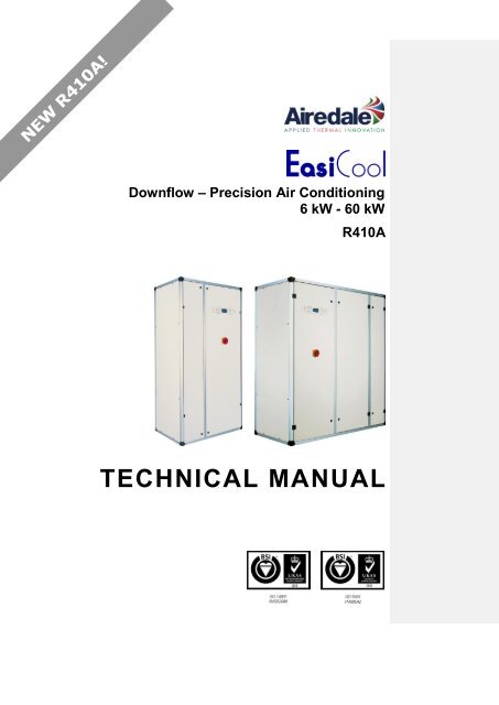
<strong>Downflow</strong> – Precision <strong>Air</strong> <strong>Conditioning</strong><br />
6 kW - 60 kW<br />
R410A<br />
TECHNICAL MANUAL
2<br />
- DF Precision <strong>Air</strong> <strong>Conditioning</strong><br />
ABOU T AIREDALE<br />
About <strong><strong>Air</strong>edale</strong> Products & Customer Services<br />
WARRANTY<br />
Warranty is only valid in the<br />
event that<br />
CAUTION<br />
SPARES<br />
TRAINING<br />
All AIAC products or parts (non consumable) supplied for installation within the UK mainland and<br />
commissioned by an AIAC engineer, carry a full Parts & Labour warranty for a period of 12 months<br />
from the date of commissioning or 18 months from the date of despatch, whichever is the sooner.<br />
Parts or Equipment supplied by AIAC for installation within the UK or for Export that are properly<br />
commissioned in accordance with AIAC standards and specification, not commissioned by an AIAC<br />
engineer; carry a 12 month warranty on non consumable Parts only from the date of commissioning<br />
or 18 months from the date of despatch, whichever is the sooner.<br />
Parts or equipment installed or commissioned not to acceptable AIAC standards or specification<br />
invalidate all warranty.<br />
In the period between delivery and commissioning the equipment: is properly protected & serviced as<br />
per the AIAC installation & maintenance manual provided where applicable the glycol content is<br />
maintained to the correct level.<br />
In the event of a problem being reported and once warranty is confirmed as valid under the given<br />
installation and operating conditions, the Company will provide the appropriate warranty coverage<br />
(as detailed above) attributable to the rectification of any affected <strong><strong>Air</strong>edale</strong> equipment supplied<br />
(excluding costs for any specialist access or lifting equipment that must be ordered by the customer).<br />
Any spare part supplied by <strong><strong>Air</strong>edale</strong> under warranty shall be warranted for the unexpired period of<br />
the warranty or 3 months from delivery, whichever period is the longer.<br />
To be read in conjunction with the <strong><strong>Air</strong>edale</strong> Conditions of Sale - Warranty and Warranty Procedure,<br />
available upon request.<br />
Warranty cover is not a substitute for maintenance. Warranty cover is conditional to maintenance<br />
being carried out in accordance with the recommendations provided during the warranty period.<br />
Failure to have the maintenance procedures carried out will invalidate the warranty and any liabilities<br />
by <strong><strong>Air</strong>edale</strong> <strong>International</strong> <strong>Air</strong> <strong>Conditioning</strong> Ltd.<br />
A spares list for 1, 3 and 5 years will be supplied with every unit and is also available from our<br />
Spares department on request.<br />
As well as our comprehensive range of products, <strong><strong>Air</strong>edale</strong> offers a modular range of Refrigeration<br />
and <strong>Air</strong> <strong>Conditioning</strong> Training courses, for further information please contact <strong><strong>Air</strong>edale</strong>.<br />
CUSTOMER SERVICES For further assistance, please e-mail: enquiries@airedale.com or telephone:<br />
CUSTOMER SERVICES<br />
Legal Notices<br />
UK Sales Enquiries + 44 (0) 113 238 7789 enquiries@airedale.com<br />
<strong>International</strong> Enquiries + 44 (0) 113 239 1000 enquiries@airedale.com<br />
Spares Hot Line + 44 (0) 113 238 7878 spares@airedale.com<br />
<strong><strong>Air</strong>edale</strong> Service + 44 (0) 113 239 1000 service@airedale.com<br />
<strong>Technical</strong> Support + 44 (0) 113 239 1000 tech.support@airedale.com<br />
Training Enquiries + 44 (0) 113 239 1000 marketing@airedale.com<br />
For information, visit us at our Web Site: www.airedale.com<br />
AIAC Ltd endeavours to ensure that the information in this document is correct and fairly stated, but<br />
none of the statements are to be relied upon as a statement or representation of fact. AIAC Ltd does<br />
not accept liability for any error or omission, or for any reliance placed on the information contained<br />
in this document.<br />
The development of <strong><strong>Air</strong>edale</strong> products and services is continuous and the information in this<br />
document may not be up to date. It is important to check the current position with AIAC Ltd at the<br />
address stated. This document is not part of a contract or licence unless expressly agreed.<br />
No part of this document may be reproduced or transmitted in any form or by any means, electronic<br />
or mechanical, including photocopying, recording, or information storage and retrieval systems, for<br />
any purpose other than the purchaser’s personal use, without the express written permission of<br />
AIAC Ltd.<br />
2013 <strong><strong>Air</strong>edale</strong> <strong>International</strong> <strong>Air</strong> <strong>Conditioning</strong> Limited. All rights reserved. Printed in the UK.<br />
Precision <strong>Air</strong> <strong>Conditioning</strong><br />
<strong>Technical</strong> <strong>Manual</strong> : 6662647 V1.3.0 02_2013
Precision <strong>Air</strong> <strong>Conditioning</strong> - DF<br />
Contents<br />
Warranty ................................................................................................................................ 2<br />
INDOOR UNIT 4<br />
General Description ................................................................................................................... 4<br />
Unit Identification.................................................................................................................... 4<br />
Introduction ............................................................................................................................ 4<br />
Standard Features ................................................................................................................. 5<br />
Optional Extras - Energy Saving 10<br />
Optional Extras - General ..................................................................................................... 11<br />
Dimensional & Installation Data ............................................................................................. 16<br />
Dimensions .......................................................................................................................... 16<br />
Positioning ........................................................................................................................... 18<br />
Minimum Unit Clearance ...................................................................................................... 19<br />
Weights ................................................................................................................................ 20<br />
Controls .................................................................................................................................... 21<br />
Display/Keypad .................................................................................................................... 21<br />
Temperature Control ............................................................................................................ 22<br />
Alarm Handling .................................................................................................................... 23<br />
Standard Features ............................................................................................................... 24<br />
Optional Extras .................................................................................................................... 25<br />
Sound Measurement Method .................................................................................................. 26<br />
Design Features & Information ............................................................................................... 27<br />
Energy Saving Features 27<br />
General Features ................................................................................................................. 30<br />
<strong>Air</strong> & Water Cooled (X & WX) Models ..................................................................................... 32<br />
Performance Data - <strong>Air</strong> & Water Cooled Models .................................................................. 32<br />
General Specification - <strong>Air</strong> & Water Cooled Models ............................................................. 35<br />
Sound Data - <strong>Air</strong> & Water Cooled Models ............................................................................ 43<br />
Design Data - <strong>Air</strong> & Water Cooled Models ........................................................................... 44<br />
Chilled Water (CW) Models ..................................................................................................... 52<br />
Performance Data - Chilled Water Models ........................................................................... 52<br />
General Specification - Chilled Water Models ...................................................................... 53<br />
Sound Data - Chilled Water Models ..................................................................................... 59<br />
Design Data - Chilled Water Models .................................................................................... 60<br />
OUTDOOR UNIT 64<br />
General Description ............................................................................................................ 64<br />
Optional Extras - Energy Saving 66<br />
Dimensional & Installation Data .......................................................................................... 68<br />
Installation Data .................................................................................................................. 70<br />
Sound Data ......................................................................................................................... 72<br />
General Specification .......................................................................................................... 73<br />
Precision <strong>Air</strong> <strong>Conditioning</strong><br />
<strong>Technical</strong> <strong>Manual</strong> : 6662647 V1.3.0 02_2013<br />
3
GENERAL<br />
INDOOR UNIT<br />
General Description<br />
UNIT IDENTIFICATION<br />
4<br />
- DF Precision <strong>Air</strong> <strong>Conditioning</strong><br />
DF <strong>Downflow</strong> Configuration<br />
6 - 60 Model Size (Expressed as Nominal Cooling in kW)<br />
X <strong>Air</strong> Cooled Remote Condenser<br />
WX Water Cooled<br />
CW Chilled Water<br />
2 Tandem Compressor Set<br />
EZR Series - EasiCool R410A<br />
Precision <strong>Air</strong> <strong>Conditioning</strong><br />
<strong>Technical</strong> <strong>Manual</strong> : 6662647 V1.3.0 02_2013<br />
DF 22 X 2 - EZR<br />
INTRODUCTION Designed to provide environmental Precision air conditioning for applications such as<br />
Telecommunication Facilities, Computer Rooms, Clean Rooms and laboratories, the<br />
EasiCool range comprises 17 models as direct expansion air cooled, 17 models as water<br />
cooled and 17 models as chilled water all of which are single circuit. Full function units<br />
provide full control of temperature, humidity and filtration.<br />
CE DIRECTIVE<br />
The modular design of the EasiCool allows grouping of differing model types and<br />
capacities to be installed side by side. The flexibility of this type of installation provides for<br />
multi-circuit functionality.<br />
A full range of air cooled condensers is available with the direct expansion indoor units to<br />
provide a matched system with optional performance upgrade, refer to Outdoor Unit, on<br />
page 64.<br />
Also available is a full range of <strong><strong>Air</strong>edale</strong> water chillers to complement the chilled water<br />
indoor units.<br />
The range has been designed and optimised for operation with ozone benign<br />
refrigerant R410A.<br />
This manual covers the full range of <strong>Downflow</strong> configured models. For Upflow<br />
configured models, please refer to the Upflow <strong>Technical</strong> <strong>Manual</strong>.<br />
<strong><strong>Air</strong>edale</strong> certify that the equipment detailed in this manual conforms with the following<br />
EC Directives:<br />
Electromagnetic Compatibility Directive (EMC) 2004/108/EC<br />
Low Voltage Directive (LVD) 73/23/EEC<br />
Machinery Directive (MD) 89/392/EEC in the version 98/37/EC<br />
Pressure Equipment Directive (PED) 97/23/EC<br />
To comply with these directives appropriate national & harmonised standards have been<br />
applied. These are listed on the Declaration of Conformity, supplied with each product.
Precision <strong>Air</strong> <strong>Conditioning</strong> - DF<br />
General Description<br />
STANDARD FEATURES<br />
Construction The cabinet comprises an anodised aluminium frame with black nylon corners and<br />
removable galvanised sheet steel panels. The unit panels are manufactured from<br />
galvanised sheet steel coated with epoxy baked powder paint to provide a durable finish.<br />
Standard unit colour is Light Grey (RAL 7035).<br />
Cabinets are lined internally with fire resistant foam (UL94 V0) thermal and<br />
acoustic insulation:<br />
30mm deep for removable panels<br />
12mm deep for remaining internal surfaces<br />
The cabinet doors are full height, hinged and key lock secured. Hinge arrangement allows<br />
flexible door opening/removal for improved access.<br />
Rubberised door seals reduce sound breakout and eradicate leakage.<br />
Simple bolt on type doors are available as a cost effective option, please refer to Bolt on<br />
Doors, on page 12.<br />
For ease of maintenance, the control panel door may be safely opened while the unit is<br />
in operation.<br />
Unit design incorporates a series of M6 fixings to the top and bottom face for connecting<br />
to customer ductwork, please contact <strong><strong>Air</strong>edale</strong> for further details.<br />
Sizes 6 - 26 Dependent upon model type, components such as the expansion valve, compressor,<br />
humidifier and sight glass are contained within an acoustically lined enclosure to provide<br />
both ease of maintenance and to minimise sound emission.<br />
Evaporator Large surface area coil(s) ideally positioned to optimise airflow and heat transfer,<br />
manufactured from refrigeration quality copper tube with mechanically bonded<br />
aluminium fins.<br />
The copper tube is internally rifled for improved heat transfer.<br />
Fins are coated with a non-stick acrylic film (hydrophilic) which provides additional<br />
corrosion protection and efficient surface water removal for improved performance.<br />
The cooling coil is mounted over a full width stainless steel condensate tray.<br />
Factory pressure tested to 45Bar.<br />
X Models Only Sweat copper pipe for brazed connection as standard.<br />
Condenser<br />
(WX Models)<br />
Stainless steel high efficiency brazed plate heat exchanger(s) will allow optimum heat<br />
transfer between media.<br />
Factory pressure tested to 45Bar.<br />
Sweat copper pipe for brazed connection as standard. Optional threaded connections<br />
available refer to Threaded Water Pipe Connection, on page 14.<br />
Precision <strong>Air</strong> <strong>Conditioning</strong><br />
<strong>Technical</strong> <strong>Manual</strong> : 6662647 V1.3.0 02_2013<br />
5<br />
GENERAL
GENERAL<br />
General Description<br />
STANDARD FEATURES<br />
Chilled Water Coil<br />
(CW Models)<br />
Fan & Motor Assembly - AC Motor<br />
Sizes 6 - 26<br />
(Direct Drive)<br />
6<br />
- DF Precision <strong>Air</strong> <strong>Conditioning</strong><br />
Large surface area coil(s) ideally positioned to optimise airflow and heat transfer,<br />
manufactured from refrigeration quality copper tubes with mechanically bonded<br />
aluminium fins.<br />
Fins are coated with a non-stick acrylic film (hydrophilic) which provides additional<br />
corrosion protection and efficient surface water removal for improved performance.<br />
The cooling coil is mounted over a full width stainless steel condensate tray.<br />
For control of water flow, a 3 port, raise/lower type, modulating mixing control valve is<br />
fitted as standard.<br />
Maximum operating pressure 10bar. Factory pressure tested to 20Bar.<br />
Sweat copper pipe for brazed connection as standard. Optional threaded connections<br />
available refer to Threaded Water Pipe Connection, on page 14.<br />
Units utilise a double inlet, forward curved, direct drive centrifugal fan with integral shaft<br />
mounted AC motor which is statically and dynamically balanced for quiet operation.<br />
Impellers and casings are galvanised for protection against corrosion. The integral motor<br />
runs in sealed for life, lubricated bearings and features automatic thermal<br />
overload protection.<br />
Fan speed, airflow and external static pressure are controlled by the use of a manually<br />
adjustable voltage controller via the microprocessor display keypad which offers easy on<br />
site adjustment.<br />
Adjustable by increments of 1% within + / - 10% of the set point.<br />
Sizes 6 - 17 Units have a single fan and motor assembly.<br />
Sizes 20 - 26 Units have 2 fan and motor assemblies.<br />
Large AC fan motor options available to most sizes, refer to Mechanical Data, on page<br />
35 & 53.<br />
Energy efficient Electronically Commutated (EC) fans are also available; refer to Optional<br />
Extras - Energy Saving, on page 10.<br />
Precision <strong>Air</strong> <strong>Conditioning</strong><br />
<strong>Technical</strong> <strong>Manual</strong> : 6662647 V1.3.0 02_2013
Precision <strong>Air</strong> <strong>Conditioning</strong> - DF<br />
General Description<br />
STANDARD FEATURES<br />
Fan & Motor Assembly - AC Motor<br />
Sizes 28 - 60<br />
(Belt & Pulley)<br />
Double inlet forward curved centrifugal fan(s) with galvanised impellers and casing.<br />
Mild steel fan shaft with lifetime lubricated ball bearings.<br />
Fan and drive assembly design is based on a minimum of 25,000 hours life expectancy.<br />
Each fan assembly is separately driven by a high efficiency air cooled AC motor through<br />
a pulley and ‘V’ belt drive. The complete motor assembly is mounted on a fully adjustable<br />
platform for belt tensioning. Motor specification conforms to Efficiency Class 2 (EFF2).<br />
With integrated plummer block bearings (4kW motors only).<br />
Sizes 28 - 45 Units have a single fan and motor assembly.<br />
Sizes 50 - 60 Units have 2 fan and motor assemblies.<br />
Large AC fan motor options available to most sizes, refer to Mechanical Data, on page<br />
35 & 53.<br />
Energy efficient Electronically Commutated (EC) fans are also available; refer to Optional<br />
Extras - Energy Saving, on page 10.<br />
<strong>Air</strong>flow Switch An adjustable differential pressure switch activates a visual alarm at the status panel and<br />
breaks the power supply in the event of a fan or motor failure.<br />
Compressor Compressor(s) are mounted on the base via the use of vibration isolators. Each<br />
compressor is designed for use with R410A refrigerant.<br />
X & WX Models Utilise a single hermetic scroll compressor fitted as standard with:<br />
Thermal motor protection Internal or external (dependent upon model size)<br />
High temperature discharge protection<br />
X2 & WX2 Models Utilise a Tandem hermetic scroll compressor set, to provide 2 stages of control, fitted as<br />
standard with:<br />
Thermal motor protection Internal or external (dependent upon model size)<br />
High temperature discharge protection<br />
Sight glass<br />
For further details, refer to Energy Saving Features, on page 27<br />
Precision <strong>Air</strong> <strong>Conditioning</strong><br />
<strong>Technical</strong> <strong>Manual</strong> : 6662647 V1.3.0 02_2013<br />
7<br />
GENERAL
GENERAL<br />
General Description<br />
STANDARD FEATURES<br />
8<br />
- DF Precision <strong>Air</strong> <strong>Conditioning</strong><br />
Refrigeration Each refrigeration circuit features as standard:<br />
X Models Externally equalised thermostatic expansion valve (TEV)<br />
Sight glass<br />
Filter drier (loose)<br />
Low pressure switch - manual reset<br />
High pressure switch - manual reset<br />
Liquid line pressure transducer<br />
Holding charge of Inert Gas<br />
WX Models Externally equalised thermostatic expansion valve (TEV)<br />
Sight glass<br />
Head Pressure Control (3 way valve)<br />
Filter drier<br />
Low pressure switch - manual reset<br />
High pressure switch - manual reset<br />
Liquid line pressure transducer<br />
Full operating charge of R410A<br />
Bleed valve<br />
Binder points<br />
Head Pressure Control -<br />
Intelligent Modulation<br />
(X Models)<br />
Head Pressure Control -<br />
Intelligent Modulation<br />
(WX Models)<br />
The system is fitted with a voltage regulating fan speed controller which allows set point<br />
adjustment and system monitoring via the indoor unit<br />
microprocessor controller.<br />
A pressure transducer is fitted to the liquid line which in turn feeds back the head<br />
pressure to the microprocessor. The condenser fan speed can then modulate via the<br />
controller to provide optimum control under varying ambient conditions. The head<br />
pressure can be monitored via the display keypad.<br />
Units fitted with thermostatic expansion valves (TEV) have the head pressure factory set<br />
to 26 barg (377 psig).<br />
Units fitted with optional electronic expansion valves (EEV) have the head pressure<br />
factory set to 22 barg (319 psig).<br />
A 3 way regulating valve, electronically actuated via the microprocessor, utilises a liquid<br />
line pressure transducer to measure and adjust head pressure. The valve will allow<br />
cooling water to flow to the condenser, to bypass the condenser, or to allow water flow to<br />
both condenser and by-pass line in order to maintain correct refrigerant head pressure.<br />
The head pressure can be monitored via the display keypad.<br />
Precision <strong>Air</strong> <strong>Conditioning</strong><br />
<strong>Technical</strong> <strong>Manual</strong> : 6662647 V1.3.0 02_2013
Precision <strong>Air</strong> <strong>Conditioning</strong> - DF<br />
General Description<br />
STANDARD FEATURES<br />
Filters Pleated disposable panel filters in a rigid frame. Conform to BS EN 779-G4.<br />
Access and removal from unit front.<br />
As standard the microprocessor provides an alarm following a pre set run<br />
time limit being exceeded, refer to Filter Change Alarm, on page 24.<br />
Electrical The control panel contains the necessary compressor starter contactors, transformer, sub<br />
circuit protection, volt free contacts for a common alarm and mains and inter-connecting<br />
terminals. The panel is situated within the cabinet and can be removed for essential<br />
maintenance of other components within the unit. The electrical control panels are wired<br />
to the latest European standards and codes of practice.<br />
Sub Fusing The electrical mains supply for the system’s outdoor unit is supplied via the indoor unit.<br />
MCBs are fitted for protection.<br />
Main Electric Isolator To ensure complete unit isolation of the electrical panel during adjustment and<br />
maintenance a door interlocking isolator is provided as standard.<br />
Controls Units are fitted with the microprocessor controller which offers powerful<br />
analogue and digital control to meet a wide range of monitoring and control requirements.<br />
Includes a communication port plus networking and BMS connections.<br />
An 8 x 22 character, white backlit LCD door mounted display keypad assembly is used to<br />
view the unit status and allow operator adjustment. Using a combination of text and<br />
standard Icons, the unit display is easy to read and interpret.<br />
The standard display keypad visually displays operating alarms by flashing the relevant<br />
icon, however, as an optional extra; a display keypad with audible alarms is available.<br />
For full details, please refer to Controls, on page 21.<br />
Precision <strong>Air</strong> <strong>Conditioning</strong><br />
<strong>Technical</strong> <strong>Manual</strong> : 6662647 V1.3.0 02_2013<br />
9<br />
GENERAL
GENERAL<br />
General Description<br />
10<br />
- DF Precision <strong>Air</strong> <strong>Conditioning</strong><br />
OPTIONAL EXTRAS - ENERGY SAVING<br />
Electronically<br />
Commutated (EC) Fan<br />
Motor<br />
Sizes 6 - 60<br />
Electronic Expansion<br />
Valves (EEV)<br />
(X & WX Models)<br />
Suction Throttle Valve<br />
(X & WX Models, except<br />
Tandem X2 & WX2 Types)<br />
Hot Gas Re-Heat (HGRH)<br />
(X Models)<br />
Precision <strong>Air</strong> <strong>Conditioning</strong><br />
<strong>Technical</strong> <strong>Manual</strong> : 6662647 V1.3.0 02_2013<br />
Backward curved impellers, direct drive centrifugal fan assemblies with integral<br />
rotor mounted motor which is statically and dynamically balanced for<br />
quiet operation.<br />
Designed for high corrosion resistance, the impellers are laser welded<br />
aluminium with a galvanised rotor and die cast aluminium EC power module.<br />
EC motors incorporate integrated electronics to convert AC power to DC for<br />
efficient and accurate speed control and are adjustable via the microprocessor<br />
display keypad.<br />
The fans offer maximum airflow performance while keeping sound levels to<br />
a minimum.<br />
The fans are mounted within a floorstand complete with adjustable feet, optional<br />
legs and floor tile lip. Height of the floorstand; please specify at order, (refer to<br />
Dimensions, on page 19).<br />
For further details refer to Energy Saving Features, on page 27.<br />
Electronic expansion valves differ to the normal thermostatic expansion valves<br />
in their ability to maintain control of the suction superheat at reduced head<br />
pressures. This can lead to significant energy savings particularly at reduced<br />
loading and low ambient temperatures.<br />
EEV step position, superheat setpoint, head pressure set point and other<br />
features can be viewed and adjusted via the microprocessor display.<br />
Factory fitted, for further details refer to Energy Saving Features, on page 28.<br />
The valve can be selected for units fitted with EEVs.<br />
By measuring the return air temperature the microprocessor can reduce the<br />
cooling output from 100% to 50% as required.<br />
Factory fitted, for further details refer to Energy Saving Features, on page 29.<br />
The HGRH system consists of a heating coil and solenoid valve(s) and can be<br />
fitted to units with humidification selected.<br />
The microprocessor monitors the temperature and humidity setpoints and<br />
initiates HGRH to provide optimum system efficiency.<br />
Factory fitted, for further details refer to Energy Saving Features, on page 29.<br />
CAUTION HGRH may be fitted instead of electric heating or low pressure hot water.<br />
Energy Manager Analysis of system energy consumption can be monitored via a dedicated LCD<br />
display. Unit parameters can be adjusted via the unit microprocessor control to<br />
affect energy usage in line with the system need.<br />
CAUTION If Phase Rotation Protection and an Energy Manager unit are both<br />
required, the Energy Manager will require the addition of a Field Card,<br />
please contact <strong><strong>Air</strong>edale</strong>.
Precision <strong>Air</strong> <strong>Conditioning</strong> - DF<br />
General Description<br />
OPTIONAL EXTRAS - GENERAL<br />
Low Noise Feature for<br />
Condenser Fan<br />
(X Models)<br />
Humidifier - Intelligent<br />
Modulation<br />
Water Conductivity &<br />
Cylinder Type<br />
Specifically designed for night time operation as optimum low noise levels are achieved<br />
with reduced ambient temperature and room loads, this feature is also ideal for residential<br />
and other outdoor noise critical applications.<br />
Initiated by setting the microprocessor programmable time clock, the head pressure set<br />
point changes from the standard 26 barg (377 psig) (TEV) or 22 barg (319 psig) (optional<br />
EEV) to 34 barg (493 psig), reducing the outdoor unit fan speed and corresponding<br />
operating sound levels.<br />
This feature is enabled by the inclusion of an optional clock card within<br />
the microprocessor.<br />
Humidification is provided by an electrode boiler. The sealed humidifier design ensures<br />
that only clean sterile steam is supplied to the conditioned area and corrosive salts and<br />
minerals are held in the disposable bottle. The steam is distributed through a sparge pipe<br />
fitted to the coil assembly.<br />
Featuring modulating capacity output control as standard, the system provides<br />
continuous modulation of steam output in response to a proportional control signal. The<br />
output control range is 20%-100% of the humidifier rated value and is designed to give an<br />
approximate steam output of +/- 3% at 25°C at the sensor, thus ensuring precise control<br />
of the conditioned space.<br />
The cylinder operating life time is automatically optimised via the integrated water<br />
conductivity sensor, which combined with the controls monitors and regulates<br />
the water refill cycle to reduce excessive salt deposits and the progressive wear of the<br />
cylinder. For further details, refer to Humidification, on page 31.<br />
All humidifier parameters and alarms are accessible and adjustable via the<br />
microprocessor display keypad unit, main features include:<br />
Supply water conductivity (S/cm)<br />
Actual steam output (kg/h)<br />
Required steam output (kg/h)<br />
Actual current rating (A)<br />
Required current rating (A)<br />
Status mode (Start Up, Running, Filling, Draining)<br />
Conductivity is a measure of the ability of water to pass an electric current, measured in<br />
micro Siemens / centimetre (S/cm). 3 different cylinders are available which correspond<br />
to the supply water conductivity.<br />
Matching the correct cylinder type with the conductivity of the supply water ensures<br />
optimum performance and increases the life span of the cylinder.<br />
1 Low Conductivity (Soft Water) 100 to 350 S/cm<br />
2 Standard Conductivity (Moderate/Hard Water) 350 to 750 S/cm<br />
3 High Conductivity (Very Hard Water) 750 to 1250 S/cm<br />
As standard the humidifier is fitted with the standard conductivity cylinder which covers<br />
the majority of water supplies. Where the water conductivity is known, please specify at<br />
order. For further details please contact <strong><strong>Air</strong>edale</strong>.<br />
CAUTION The supply water pressure to the humidifier assembly must be between 1 - 8 barg.<br />
Precision <strong>Air</strong> <strong>Conditioning</strong> 11<br />
<strong>Technical</strong> <strong>Manual</strong> : 6662647 V1.3.0 02_2013<br />
GENERAL
GENERAL<br />
General Description<br />
OPTIONAL EXTRAS - GENERAL<br />
Heating Options<br />
Hot Gas Re-Heat (HGRH)<br />
(X Models)<br />
12<br />
- DF Precision <strong>Air</strong> <strong>Conditioning</strong><br />
Refer to Hot Gas Re-Heat (HGRH), on page 10.<br />
Or<br />
Electric Heating Multi-stage finned electric heating elements complete with auto and manual reset<br />
overheat cut-out protection.<br />
Electric Heating Thyristor<br />
Control<br />
Standard electric heating elements are phase balanced for increased efficiency.<br />
Offers precision control between 0 - 100% via the microprocessor.<br />
Or<br />
Low Pressure Hot Water A low pressure hot water coil constructed of refrigeration quality copper tube and<br />
mechanically bonded aluminium fins can be factory fitted.<br />
Larger & Next Larger<br />
Fan Motor<br />
(AC Fan Motors Only)<br />
Condensate Pump<br />
Frost protection is fitted to prevent freezing of the low pressure hot water coil assembly.<br />
Proportional heating control is provided by a factory fitted 3 port, raise/lower type,<br />
modulating valve.<br />
Access to the RHS of the unit is required to set up the regulating valve, refer to<br />
Dimensional & Installation Data, on page 16.<br />
For applications where higher static air pressures are required, a larger fan and motor<br />
assembly size can be fitted to replace the standard assembly and is available to<br />
most models.<br />
Refer to Mechanical Data, on page 35 and 53 for availability.<br />
Sizes 6 - 26 The condensate pump has a 3 litre reservoir with a capacity of 5 l/m at a head of 8m and<br />
is mounted in the unit base.<br />
Sizes 28 - 60 The condensate pump has a 6 litre reservoir with a capacity of 5 l/m at a head of 10.8m<br />
and is mounted in the unit base.<br />
Bolt on Doors Simple bolt on cabinet doors can be factory fitted as a cost reduction option. The cabinet<br />
doors are full height and secured by M6 bolts, a 4mm Allen key is provided for access.<br />
Plain Doors - No Display<br />
Keypad<br />
Networking is a standard option of the <strong>Air</strong>eTronix microprocessor; refer to Controls, on<br />
page 21 for full details. To reduce costs, the “slave” units can be supplied with plain doors<br />
(no display keypad), in all door types, please specify at order.<br />
Precision <strong>Air</strong> <strong>Conditioning</strong><br />
<strong>Technical</strong> <strong>Manual</strong> : 6662647 V1.3.0 02_2013
Precision <strong>Air</strong> <strong>Conditioning</strong> - DF<br />
General Description<br />
OPTIONAL EXTRAS - GENERAL<br />
Open & Enclosed<br />
Floorstand<br />
Discharge <strong>Air</strong><br />
Configuration<br />
Open or enclosed floorstands are available, complete with adjustable feet and floor tile<br />
lip. Enclosed floorstands incorporate an air turning vane. Height of the floorstand; please<br />
specify at order, refer to Dimensions, on page 19<br />
Standard configuration is forward air discharge. Reverse air discharge is available,<br />
please specify at order, refer to Dimensions, on page 15.<br />
Ceiling Duct Extension Straight and ‘L’ shaped duct extensions up to a height of 1350mm constructed and<br />
finished to match the unit are available.<br />
Services Side Access<br />
Gland Plate<br />
For extensions greater than 1350mm, please contact <strong><strong>Air</strong>edale</strong>.<br />
Height; please specify at order.<br />
As standard services can be routed through the gland plate in the base of the units. A<br />
gland plate can be optionally located to the lower left hand side face of the unit, if<br />
required, refer to Positioning, on page 18.<br />
Water Detector 2 methods are available:<br />
1 A solid state (probe) sensor is supplied loose for remote mounting on site.<br />
2 Tape suitable for sensing water droplets is supplied loose for remote mounting on<br />
site. Standard tape length 10m.<br />
Firestat Installed in the return air stream to shut down the unit in the event of an unusually high<br />
return air temperature.<br />
Precision <strong>Air</strong> <strong>Conditioning</strong> 13<br />
<strong>Technical</strong> <strong>Manual</strong> : 6662647 V1.3.0 02_2013<br />
GENERAL
GENERAL<br />
General Description<br />
OPTIONAL EXTRAS - GENERAL<br />
14<br />
- DF Precision <strong>Air</strong> <strong>Conditioning</strong><br />
Smoke Detector Supplied loose for remote mounting to shut down the unit and activate the alarm upon<br />
sensing the presence of smoke.<br />
Chilled Water Bypass<br />
Balancing Valves<br />
(CW Models)<br />
2 Port Chilled Water<br />
Control Valve<br />
(CW Models)<br />
0-10 Volt DC Chilled<br />
Water Regulating Valve<br />
(CW Models)<br />
Threaded Water Pipe<br />
Connection<br />
(WX & CW Models)<br />
Phase Rotation<br />
Protection<br />
(X & WX Models)<br />
CAUTION<br />
Bypass balancing valves can be fitted to aid commissioning and unit operation by<br />
creating the same pressure drop through the bypass as through the chilled water coil.<br />
For systems with variable speed pumps and water flow, a 2 port control valve can be<br />
fitted in place of the standard 3 port valve.<br />
Designed to optimise the regulation of water flow for special applications. A 0-10 volt DC<br />
chilled water regulating valve can be fitted in place of the standard raise/lower<br />
regulating valve.<br />
As an alternative to brazed water pipe connections, BSP brass male taper threaded<br />
connections can be factory fitted.<br />
A phase sequence relay is available for units containing 3 phase scroll compressors, to<br />
prevent possible damage by running the compressor in the wrong direction.<br />
If Phase Rotation Protection and an Energy Manager unit are both required, the<br />
Energy Manager will require the addition of a Field Card, please contact <strong><strong>Air</strong>edale</strong>.<br />
Export Packing Units can be supplied packed inside a case to provide additional protection during<br />
transportation, (not required for container delivery).<br />
Standard construction material is solid wood.<br />
Optionally, construction can be of pest treated manufactured board (Stirling Board).<br />
Please specify at order.<br />
Precision <strong>Air</strong> <strong>Conditioning</strong><br />
<strong>Technical</strong> <strong>Manual</strong> : 6662647 V1.3.0 02_2013
Precision <strong>Air</strong> <strong>Conditioning</strong> - DF<br />
Notes:<br />
Precision <strong>Air</strong> <strong>Conditioning</strong> 15<br />
<strong>Technical</strong> <strong>Manual</strong> : 6662647 V1.3.0 02_2013<br />
GENERAL
GENERAL<br />
16<br />
- DF Precision <strong>Air</strong> <strong>Conditioning</strong><br />
Dimensional & Installation Data<br />
DIMENSIONS<br />
DF6 - DF26 - Standard <strong>Air</strong>flow Configuration (mm) with Standard AC Fan Motors<br />
670<br />
640<br />
15<br />
1940<br />
200<br />
270<br />
C<br />
6 - 10 13 - 17 20 - 26<br />
670 990 1310<br />
D<br />
B<br />
A<br />
200<br />
Precision <strong>Air</strong> <strong>Conditioning</strong><br />
<strong>Technical</strong> <strong>Manual</strong> : 6662647 V1.3.0 02_2013<br />
F<br />
G<br />
15<br />
C<br />
D<br />
B<br />
A<br />
7<br />
C D E D<br />
6<br />
4<br />
B B<br />
A<br />
5<br />
1 2<br />
H x D x W A B C (8) D (8) E F (9) G (8)<br />
DF6 X/WX/CW mm 1940 x 670 x 670 640 270 216 (183) 238 (304) N/A 50 (157) 268 (268)<br />
DF8 X/WX/CW mm 1940 x 670 x 670 640 270 183 (167) 304 (337) N/A 50 (157) 268 (295)<br />
DF10 X/WX/CW mm 1940 x 670 x 670 640 270 167 (N/A) 337 (N/A) N/A 50 (186) 295 (N/A)<br />
DF13 X/WX/CW mm 1940 x 670 x 990 960 590 326 (N/A) 337 (N/A) N/A 50 (186) 295 (N/A)<br />
DF15 X/WX/CW mm 1940 x 670 x 990 960 590 294 (N/A) 401 (N/A) N/A 50 (210) 347 (N/A)<br />
DF17 X/WX/CW mm 1940 x 670 x 990 960 590 294 (N/A) 401 (N/A) N/A 50 (210) 347 (N/A)<br />
DF20 X2/WX2/CW mm 1940 x 670 x 1310 1280 455 166 (N/A) 337 (N/A) 303 50 (186) 295 (N/A)<br />
DF22 X2/WX2/CW mm 1940 x 670 x 1310 1280 455 166 (N/A) 337 (N/A) 303 50 (186) 295 (N/A)<br />
DF26 X2/WX2/CW mm 1940 x 670 x 1310 1280 455 166 (N/A) 337 (N/A) 303 50 (186) 295 (N/A)<br />
(1) Standard forward airflow direction.<br />
(2) Optional reverse airflow direction.<br />
(3) Optional gland plate and panel for side services access via the right side of unit. For services details contact <strong><strong>Air</strong>edale</strong>.<br />
(4) Base mains cable entry.<br />
(5) Standard base gland plate entry for refrigeration/water services. For services details contact <strong><strong>Air</strong>edale</strong>.<br />
(6) Shaded area denotes fan discharge aperture. Optional EC fan motor discharge aperture provided with protective mesh, not shown.<br />
(7) M6 fixing hole positions.<br />
(8) Figures in brackets represent position of fan discharge aperture when larger AC fan motor option is fitted.<br />
(9) Figures in brackets represent optional reverse air discharge configuration when fitted with standard AC fan motors.<br />
(10) Units fitted with optional EC fan motors require a floorstand; refer to Dimensions, on page 19.<br />
3
Precision <strong>Air</strong> <strong>Conditioning</strong> - DF<br />
750<br />
Dimensional & Installation Data<br />
DIMENSIONS<br />
DF28 - DF60 - Standard <strong>Air</strong>flow Configuration (mm) with Standard AC Fan Motors<br />
20<br />
710<br />
330<br />
210<br />
1940<br />
28 - 31<br />
C<br />
1460<br />
D<br />
B B B<br />
A<br />
F<br />
G<br />
210<br />
20<br />
35 - 45<br />
C<br />
1835<br />
D<br />
B B B<br />
A<br />
4<br />
50 - 60<br />
D<br />
E<br />
2170<br />
B B B B<br />
A<br />
1 2<br />
H x D x W A B C (8) D (8) E F (9) G (8)<br />
DF28 X/WX/CW mm 1940 x 750 x 1460 1420 347 540 379 N/A 91 (113) 546<br />
DF31 X/WX/CW mm 1940 x 750 x 1460 1420 347 540 379 N/A 91 (113) 546<br />
DF35 X/WX/CW mm 1940 x 750 x 1835 1795 472 679 477 N/A 91 (113) 546<br />
DF40 X/WX/CW mm 1940 x 750 x 1835 1795 472 679 477 N/A 91 (113) 546<br />
DF45 X/WX/CW mm 1940 x 750 x 1835 1795 472 679 477 N/A 91 (113) 546<br />
DF50 X2/WX2/CW mm 1940 x 750 x 2170 2130 438 206 401 543 76 (257) 345<br />
DF55 X2/WX2/CW mm 1940 x 750 x 2170 2130 438 206 401 543 76 (257) 345<br />
DF60 X2/WX2/CW mm 1940 x 750 x 2170 2130 438 206 401 543 76 (257) 345<br />
(1) Standard forward airflow direction.<br />
(2) Optional reverse airflow direction.<br />
(3) Optional gland plate and panel for side services access via the right side of unit. For services details contact <strong><strong>Air</strong>edale</strong>.<br />
(4) Base mains cable entry.<br />
(5) Standard base gland plate entry for refrigeration/water services. For services details contact <strong><strong>Air</strong>edale</strong>.<br />
(6) Shaded area denotes fan discharge aperture. Optional EC fan motor discharge aperture provided with protective mesh, not shown.<br />
(7) M6 fixing hole positions.<br />
(8) Figures in brackets represent position of fan discharge aperture when larger AC fan motor option is fitted.<br />
(9) Figures in brackets represent optional reverse air discharge configuration when fitted with standard AC fan motors.<br />
(10) Units fitted with optional EC fan motors require a floorstand; refer to Dimensions, on page 19.<br />
7<br />
6<br />
C<br />
D<br />
Precision <strong>Air</strong> <strong>Conditioning</strong> 17<br />
<strong>Technical</strong> <strong>Manual</strong> : 6662647 V1.3.0 02_2013<br />
5<br />
3<br />
GENERAL
GENERAL<br />
18<br />
- DF Precision <strong>Air</strong> <strong>Conditioning</strong><br />
Dimensional & Installation Data<br />
POSITIONING<br />
<strong>Downflow</strong><br />
Standard Return and AC Fan Motors Standard Return and Optional EC Fan Motors<br />
POSITIONING<br />
IMPORTANT<br />
Precision <strong>Air</strong> <strong>Conditioning</strong><br />
<strong>Technical</strong> <strong>Manual</strong> : 6662647 V1.3.0 02_2013<br />
1 With adjustable feet fitted<br />
2 With variable size leg and adjustable feet fitted<br />
When placing the unit on the floorstand ensure appropriate inseal is used to<br />
prevent air leakage at the join.<br />
It is also important to place all locking bolts in place to secure the unit to its base<br />
(EC fan floorstands only).<br />
Comment [KSB1]:
Precision <strong>Air</strong> <strong>Conditioning</strong> - DF<br />
Dimensional & Installation Data<br />
MINIMUM UNIT CLEARANCE<br />
Open & Enclosed Floorstands Option<br />
A B C - Floorstand (3) D (4)<br />
DF6 - DF10 mm 670 610 Min 200 - Max 750<br />
Min 300<br />
DF13 - DF17 mm 990 610 (+ 50mm Feet<br />
Min 300<br />
DF20 - DF26 mm 1310 610 Adjustable +/- 20mm)<br />
Min 300<br />
DF28 - DF31 mm 1460 700 Min 300 - Max 800<br />
Min 300<br />
DF35 - DF45 mm 1835 700 (+ 50mm Feet<br />
Min 300<br />
DF50 - DF60 mm 2170 700 Adjustable +/- 20mm)<br />
Min 300<br />
EC Fan Motor Option<br />
C<br />
A B<br />
(3)<br />
D (5)<br />
With Feet Only (4) With Leg & Feet (4)<br />
Min Max Min Max<br />
DF6 - DF10 mm 670 610 284 329 604 1074 Min 300<br />
DF13 - DF17 mm 990 610 362 407 697 1152 Min 300<br />
DF20 - DF26 mm 1310 610 362 407 697 1152 Min 300<br />
DF28 - DF31 mm 1460 700 356 401 686 1146 Min 300<br />
DF35 - DF45 mm 1835 700 356 401 686 1146 Min 300<br />
DF50 - DF60 mm 2170 700 356 401 686 1146 Min 300<br />
Minimum Ceiling Clearance<br />
E<br />
Forward Only Forward & 1 Side Forward & 2 Sides All Faces<br />
DF6 - DF10 mm 470 240 160 120<br />
DF13 - DF17 mm 550 330 240 170<br />
DF20 - DF26 mm 560 370 280 190<br />
DF28 - DF31 mm 620 410 310 210<br />
DF35 - DF45 mm 640 450 350 230<br />
DF50 - DF60 mm 640 480 380 240<br />
(1) Shown with optional open floor stand.<br />
(2) Shaded area indicates minimum service and maintenance requirements.<br />
(3) Dimension C denotes recommended minimum/maximum floorstand height, refer to <strong><strong>Air</strong>edale</strong> for special applications, please specify at order.<br />
(4) Min = Threaded foot at minimum extension.<br />
Max = Threaded foot at maximum extension.<br />
(5) Dimension D refers to units fitted with LPHW which require access to the RHS of the unit to set up the regulating valve.<br />
(6) SERVICES SIDE ACCESS GLAND PLATE, OPTIONAL POSITION; ensure appropriate clearance is available to the base of the RHS of the<br />
unit if this option is selected.<br />
Precision <strong>Air</strong> <strong>Conditioning</strong> 19<br />
<strong>Technical</strong> <strong>Manual</strong> : 6662647 V1.3.0 02_2013<br />
GENERAL
GENERAL<br />
20<br />
- DF Precision <strong>Air</strong> <strong>Conditioning</strong><br />
Dimensional & Installation Data<br />
WEIGHTS<br />
Precision <strong>Air</strong> <strong>Conditioning</strong><br />
<strong>Technical</strong> <strong>Manual</strong> : 6662647 V1.3.0 02_2013<br />
Standard Evaporator Fan - AC Motor (1) Optional Evaporator Fan - EC Motor (2)<br />
Machine (AHU) (3) Operating (AHU) Machine (AHU) (3) Operating (AHU) Floorstand<br />
DF6X kg 193 - 184 - 26<br />
DF8X kg 201 - 187 - 26<br />
DF10X kg 206 - 189 - 26<br />
DF13X kg 226 - 210 - 29<br />
DF15X kg 237 - 213 - 29<br />
DF17X kg 238 - 214 - 29<br />
DF20X2 kg 307 - 271 - 44<br />
DF22X2 kg 307 - 271 - 44<br />
DF26X2 kg 311 - 275 - 44<br />
DF28X kg 414 - 380 - 125<br />
DF31X kg 419 - 375 - 125<br />
DF35X kg 477 - 430 - 128<br />
DF40X kg 500 - 439 - 128<br />
DF45X kg 553 - 492 - 128<br />
DF50X2 kg 621 - 562 - 190<br />
DF55X2 kg 638 - 579 - 190<br />
DF60X2 kg 638 - 573 - 190<br />
DF6WX kg 209 211 200 202 26<br />
DF8WX kg 221 222 207 208 26<br />
DF10WX kg 225 226 208 209 26<br />
DF13WX kg 249 250 233 234 29<br />
DF15WX kg 267 269 243 245 29<br />
DF17WX kg 271 273 247 249 29<br />
DF20WX2 kg 348 350 312 314 44<br />
DF22WX2 kg 348 350 312 314 44<br />
DF26WX2 kg 351 354 315 318 44<br />
DF28WX kg 470 476 436 442 125<br />
DF31WX kg 475 481 431 437 125<br />
DF35WX kg 537 543 490 496 128<br />
DF40WX kg 565 571 504 510 128<br />
DF45WX kg 640 650 579 589 128<br />
DF50WX2 kg 712 722 653 663 190<br />
DF55WX2 kg 731 741 672 682 190<br />
DF60WX2 kg 731 741 666 676 190<br />
DF6CW kg 155 - 146 - 26<br />
DF8CW kg 165 - 151 - 26<br />
DF10CW kg 168 - 151 - 26<br />
DF13CW kg 195 - 179 - 29<br />
DF15CW kg 200 - 176 - 29<br />
DF17CW kg 200 - 176 - 29<br />
DF20CW kg 252 - 216 - 44<br />
DF22CW kg 252 - 216 - 44<br />
DF26CW kg 252 - 216 - 44<br />
DF28CW kg 351 - 317 - 125<br />
DF31CW kg 354 - 310 - 125<br />
DF35CW kg 410 - 363 - 128<br />
DF40CW kg 431 - 370 - 128<br />
DF45CW kg 442 - 381 - 128<br />
DF50CW kg 486 - 427 - 190<br />
DF55CW kg 499 - 440 - 190<br />
DF60CW kg 495 - 430 - 190<br />
(1) Weights quoted for units fitted with the standard AC fan motor include the cooling fan weight within the unit cabinet (AHU).<br />
(2) Weights quoted for units fitted with the optional EC fan motor exclude the cooling fan weight within the unit cabinet (AHU).<br />
(3) Machine weight includes a refrigerant charge / Operating weight includes calculated water volume, refer to Mechanical Data, on page 35.
Precision <strong>Air</strong> <strong>Conditioning</strong> - DF<br />
Controls<br />
GENERAL As standard the units are supplied with an microprocessor controller<br />
connected to a back-lit LCD keypad display.<br />
The microprocessor controller can be linked together locally to provide<br />
run/standby operation. Windows based supervisor software is also available for local or<br />
remote networking. This modular approach provides great flexibility while at the same<br />
time reducing installation and maintenance costs.<br />
DISPLAY/KEYPAD The display keypad features a simple array of keys to navigate through the in<br />
built menus.<br />
Standard Icons<br />
With an 8 x 22 character (132 x 64 pixel) screen size, back lit in white for improved<br />
contrast, the larger screen provides for user friendly viewing and easy status recognition<br />
by displaying a combination of text and icons.<br />
The default screen shows the unit status and room condition (°C/RH %) without the need<br />
for interrogation and an easy to navigate menu structure for further interrogation<br />
and adjustment.<br />
Fan operating<br />
Cooling - up to 2 stages<br />
Heating - up to 4 stages<br />
De-Humidification<br />
Humidification - Variable<br />
Precision <strong>Air</strong> <strong>Conditioning</strong> 21<br />
<strong>Technical</strong> <strong>Manual</strong> : 6662647 V1.3.0 02_2013<br />
GENERAL
GENERAL<br />
TEMPERATURE<br />
CONTROL<br />
22<br />
- DF Precision <strong>Air</strong> <strong>Conditioning</strong><br />
Controls<br />
A temperature sensor is mounted in the return air with an option for a humidity sensor on<br />
full function units.<br />
The temperature sensor is a NTC type thermistor accurate up to +/- 0.25°C and the<br />
humidity sensor accurate to +/- 3% at 25°C at the sensor.<br />
The microprocessor senses the return air conditions and maintains the return<br />
air temperature and humidity conditions by controlling cooling, heating, humidification and<br />
dehumidification outputs accordingly.<br />
MONITORING The microprocessor monitors and displays the following values:<br />
Return <strong>Air</strong> Temperature<br />
Return <strong>Air</strong> Humidity (Optional on Full Function units)<br />
Condensing Pressure (Optional on DX units only)<br />
Coil Temperature Sensor (Indoor)<br />
The maintenance of key components such as compressors and air filters can be<br />
monitored via a service indicator which visually demonstrates the status relative to the<br />
component service intervals, refer to Standard Features, on page 24.<br />
ALARM LOG The controller logs and allows viewing of the last 100 conditions recorded in descending<br />
chronological order through the keypad display.<br />
The standard display keypad visually displays operating alarms, however, as an optional<br />
extra, a display keypad with audible alarms is available, refer to Optional Extras, on page<br />
25.<br />
Precision <strong>Air</strong> <strong>Conditioning</strong><br />
<strong>Technical</strong> <strong>Manual</strong> : 6662647 V1.3.0 02_2013
Precision <strong>Air</strong> <strong>Conditioning</strong> - DF<br />
Controls<br />
ALARM HANDLING An alarm will be generated under the following conditions and will be visually displayed<br />
through the alarm log. In addition, under certain conditions the relevant Icon will flash<br />
repeatedly as indicated below:<br />
Sizes 6 - 26 Return air temperature high limit<br />
Return air temperature low limit<br />
Return air humidity high limit (Optional on Full Function units)<br />
Return air humidity low limit (Optional on Full Function units)<br />
Frost protection low limit (LPHW option only)<br />
Low pressure trip (Optional on DX units only)<br />
Filter change alarm<br />
<strong>Manual</strong> override<br />
Common alarm<br />
Power fail reset<br />
Communications failure<br />
Maintenance - fan and compressor (once hours run limit exceeded)<br />
<strong>Air</strong>flow failure ( )<br />
Compressor failure (Optional on DX units only) ( )<br />
Electric Heating Overheat cut-out ( )<br />
Humidifier alarm (Full Function units only) ( )<br />
Sizes 28 - 60 Return air temperature high limit<br />
Return air temperature low limit<br />
Return air humidity high limit (Optional on Full Function units)<br />
Return air humidity low limit (Optional on Full Function units)<br />
Frost protection low limit (LPHW option only)<br />
Low pressure trip (Optional on DX units only)<br />
Filter change alarm<br />
<strong>Manual</strong> override<br />
Common alarm<br />
Power fail reset<br />
Communications failure<br />
Maintenance - fan and compressor (once hours run limit exceeded)<br />
Fire<br />
Flood<br />
Phase Failure<br />
Critical<br />
Non-critical<br />
<strong>Air</strong>flow failure ( )<br />
Compressor failure (Optional on DX units only) ( )<br />
Electric Heating Overheat cut-out ( )<br />
Humidifier alarm (Full Function units only) ( )<br />
Precision <strong>Air</strong> <strong>Conditioning</strong> 23<br />
<strong>Technical</strong> <strong>Manual</strong> : 6662647 V1.3.0 02_2013<br />
GENERAL
GENERAL<br />
STANDARD FEATURES<br />
24<br />
- DF Precision <strong>Air</strong> <strong>Conditioning</strong><br />
Controls<br />
Password Protection The control system integrity can be maintained by restricting access with a password<br />
PIN number.<br />
CAUTION<br />
IMPORTANT: To change the PIN number, please contact <strong><strong>Air</strong>edale</strong> at time of order<br />
with the preferred 4 digit number.<br />
Remote On/Off Terminals for interlocking are provided to enable or disable the unit remotely.<br />
Fire Shut Down Terminals for interlocking are provided to shut down the unit in the event of fire.<br />
Compressor Anti-Cycle<br />
Control<br />
Programmed to provide automatic anti-cycling delays of up to 10 starts per hour with a<br />
minimum off time of 3 minutes.<br />
Compressor Rotation On tandem compressor units the controller is programmed to provide automatic<br />
compressor rotation to ensure equal compressor running times. In the event of a<br />
compressor fault on networked systems the controller is programmed to automatically<br />
select the next compressor in order of running hours.<br />
Compressor Hours Run<br />
Log & Reset<br />
Evaporator Fan Hours<br />
Run Log & Reset<br />
Head Pressure Control<br />
and Condenser Fan<br />
Speed Controller<br />
Evaporator Fan Speed<br />
Controller<br />
(Sizes 6 - 26)<br />
Allows the user to monitor the running times of each compressor and reset<br />
after maintenance.<br />
Hours run log or visual service indicator provided.<br />
Allows the user to monitor the running times of the evaporator fans and reset<br />
after maintenance.<br />
Hours run log or visual service indicator provided.<br />
Each refrigerant circuit (TEV or EEV) is fitted with condenser pressure transducers and a<br />
modulating condenser fan speed controller to allow the designed head pressure to be<br />
monitored and maintained under varying ambient conditions. Condenser fan speed<br />
control settings are input via the display keypad.<br />
Evaporator fan speed control is easily set via the display keypad and can be<br />
incrementally increased or decreased to meet on site airflow and external static<br />
pressure requirements.<br />
Filter Change Alarm Filter change is managed by the <strong>Air</strong>eTronix software, and is based on fan(s) hours run<br />
with an alarm being generated when the pre-set run time limit has been exceeded. The<br />
set-point value can be adjusted to suit each application and is factory set to 2000 hours.<br />
LPHW Frost Protection<br />
(DX units with LPHW<br />
option)<br />
Hours run log or visual service indicator provided.<br />
The coil temperature sensor is mounted on the DX coil and has a fixed 3°C low limit<br />
setting to disable DX cooling.<br />
Precision <strong>Air</strong> <strong>Conditioning</strong><br />
<strong>Technical</strong> <strong>Manual</strong> : 6662647 V1.3.0 02_2013
Precision <strong>Air</strong> <strong>Conditioning</strong> - DF<br />
STANDARD NETWORK<br />
FEATURES<br />
Controls<br />
As standard the <strong>Air</strong>eTronix controller is capable of the providing a platform for the<br />
following and can be enabled on request for 2 to 6 units, please specify at order:<br />
Networking A Local Area Network ( ) can be used to connect upto 6 units to offer<br />
intercommunication and Duty/Standby control. This also allows the connection of<br />
computers, printers and modems on the same communications ring. For further details,<br />
please contact <strong><strong>Air</strong>edale</strong> Controls.<br />
CAUTION<br />
When adding to an existing network, please consult <strong><strong>Air</strong>edale</strong> to ensure<br />
strategy compatibility.<br />
Duty/Standby Operation The controller enables units to operate in run/standby mode, with up to 6 units networked<br />
together, without the need for additional hardware or controllers. Standby units can be<br />
configured to start when the run unit has a critical alarm and/or a high/low return air<br />
temperature alarm.<br />
During peak demand, the standby units can temperature assist.<br />
Duty Rotation Networked units can be configured to duty rotate, providing equal hours run of fans<br />
and compressors.<br />
OPTIONAL EXTRAS<br />
Audible Alarm The display keypad can be upgraded to include audible alerts.<br />
Real Time Clock A real time clock card can be fitted to the microprocessor to provide date and<br />
time stamping on alarms. Occupied and unoccupied set points can also be configured for<br />
temperature, humidity and head pressure control settings.<br />
This option is enabled by the inclusion of a clock card within the microprocessor, supplied<br />
as standard with this option.<br />
BMS Interface Card Enables Controlled units to be interfaced with most BMS, factory fitted,<br />
please contact <strong><strong>Air</strong>edale</strong>.<br />
Plain Doors - No Display<br />
Keypad<br />
A wide range of protocols can be accommodated through the use of interface devices.<br />
Available as a standard option are: ModBus/Jbus, Carel and Trend.<br />
For interfaces such as SNMP, LonWorks, Metasys and BACnet, please contact <strong><strong>Air</strong>edale</strong>.<br />
Also available is <strong><strong>Air</strong>edale</strong>’s own supervisory plug-in BMS card pCOWEB.<br />
Based on Ethernet TCP/IP secure technology with SNMP features.<br />
Requires no proprietary cabling or monitoring software and supplied pre programmed with<br />
an IP address for ease of set up.<br />
To reduce costs, the “slave” units can be supplied with plain doors (no display keypad),<br />
please specify at order.<br />
Precision <strong>Air</strong> <strong>Conditioning</strong> 25<br />
<strong>Technical</strong> <strong>Manual</strong> : 6662647 V1.3.0 02_2013<br />
GENERAL
GENERAL<br />
26<br />
- DF Precision <strong>Air</strong> <strong>Conditioning</strong><br />
Sound Measurement Method<br />
MEASUREMENT OF<br />
SOUND DATA<br />
All sound data quoted has been measured in the third-octave band limited values, using a<br />
Real Time Analyser calibrated sound intensity meter in accordance with BS EN ISO9614<br />
Part 1 : 1995.<br />
All Sound Power Levels quoted are calculated from measured sound intensity according<br />
to BS EN ISO9614 Part 1 : 1995.<br />
SEMI HEMISPHERICAL Sound Pressure Levels are calculated from sound power using the semi-hemispherical<br />
method where the noise source is in junction with 2 boundaries i.e. the floor and 1 wall.<br />
FREE FIELD For comparison, the semi hemispherical figures can typically be reduced by 3dB to<br />
provide free field conditions.<br />
IMPORTANT The sound data quoted is based on the unit having a ducted return air, ducted (or<br />
underfloor) discharge air and standard forward curved fan and AC motors fitted,<br />
refer to illustration below.<br />
Case breakout sound data is therefore independent of the discharge air and return<br />
air sound data.<br />
For non-ducted return air applications, the overall case breakout sound levels may<br />
increase, due to the return air sound being predominant.<br />
Within the conditioned space, sound from in-room ducted discharge air grilles and<br />
other equipment will contribute to the overall sound level and should therefore be<br />
considered as part of sound calculations.<br />
Specialist acoustic advice is recommended for noise critical applications.<br />
Precision <strong>Air</strong> <strong>Conditioning</strong><br />
<strong>Technical</strong> <strong>Manual</strong> : 6662647 V1.3.0 02_2013<br />
(1)<br />
(2)<br />
(3)<br />
(1)Return <strong>Air</strong><br />
(2)Case Breakout<br />
(3)Discharge <strong>Air</strong><br />
(1) Return <strong>Air</strong><br />
(2) Case Breakout<br />
(3) Discharge <strong>Air</strong>
Precision <strong>Air</strong> <strong>Conditioning</strong> - DF<br />
Design Features & Information<br />
ENERGY SAVING FEATURES<br />
ELECTRONICALLY<br />
COMMUTATED (EC) FAN<br />
MOTOR OPTION<br />
TANDEM<br />
COMPRESSORS<br />
40<br />
20<br />
0<br />
EC motors are DC motors with integrated AC to DC conversion; this gives the<br />
flexibility of connecting to AC mains with the efficiency and simple speed control<br />
of a DC motor. The EC fan offers significant power reduction in comparison with<br />
equivalent AC fan at both full and modulated fan speeds. The inbuilt EC fan<br />
control module allows for fan speed modulation from 15-100%, a standard AC<br />
fans modulating range is typically 40-100% of full fan speed.<br />
The EC fan presents superior energy efficiency at full and reduced fan speed<br />
compared to the equivalent AC fan motor.<br />
Standard voltage regulated (VR) fan speed controllers offer a linear response.<br />
By comparison the EC fan is adjusted on demand via the unit microprocessor<br />
with precision, offering substantial energy savings. The following illustration<br />
shows a comparison of the typical power input required by each method.<br />
Input Power<br />
<strong>Air</strong>flow<br />
Key<br />
EC (Electronically<br />
Commutated) Fan Speed<br />
Control<br />
Voltage Regulated (VR) Fan<br />
Speed Control<br />
Comprising of 2 scroll type compressors linked together by refrigerant pipework<br />
to one common circuit.<br />
Tandem compressors provide variable control of the system performance by<br />
activating individual compressors as required. Multiple steps of unloading allow<br />
external load demands to be met with greater precision, eliminating unnecessary<br />
temperature and humidity variations. Consequently, system efficiency and<br />
reliability are much improved by extending major component working hours.<br />
Precision <strong>Air</strong> <strong>Conditioning</strong> 27<br />
<strong>Technical</strong> <strong>Manual</strong> : 6662647 V1.3.0 02_2013<br />
GENERAL
GENERAL<br />
28<br />
- DF Precision <strong>Air</strong> <strong>Conditioning</strong><br />
Design Features & Information<br />
ENERGY SAVING FEATURES<br />
ELECTRONIC<br />
EXPANSION VALVES<br />
(EEV)<br />
Key:<br />
Reduced Condensing<br />
Pressure<br />
B A<br />
Pressure<br />
(bara)<br />
Evaporating Pressure<br />
B<br />
A<br />
Precision <strong>Air</strong> <strong>Conditioning</strong><br />
<strong>Technical</strong> <strong>Manual</strong> : 6662647 V1.3.0 02_2013<br />
Whilst offering versatile control at the full design duty of the unit, TEVs do not<br />
automatically optimise themselves to all operating conditions. Therefore, if the<br />
refrigeration system is operating at 40% or 50% of full load, especially at a lower<br />
ambient temperature than that for which the valve was sized, the conventional<br />
TEV must have the design head pressure available to ensure good refrigerant<br />
control. Maintaining an artificially high condensing pressure is normal in<br />
conventional systems.<br />
Using an EEV allows for good refrigeration control whilst operating at part load<br />
and lower ambient conditions with a reduced condensing pressure. By fitting an<br />
EEV and adjusting the head pressure control setting an increase in the system<br />
EER (Energy Efficiency Ratio) of up to 30% can typically be seen. The<br />
Mollier diagram shown below helps to illustrate how this increase in efficiency<br />
is achieved.<br />
EEV’s differ to normal thermostatic expansion valves in their ability to maintain<br />
control of refrigerant flow and the suction superheat at reduced head pressures.<br />
The turn-down rate of a typical EEV is superior to that of it’s thermostatic<br />
equivalent, such that a reduced optimum condensing pressure can be<br />
maintained at low compressor load. However low the load is on the compressor,<br />
from zero to 100%, there will not be a problem with turn down, even down to<br />
10% of the valves rated capacity.<br />
3<br />
3<br />
Increase in<br />
Cooling Duty<br />
4<br />
4<br />
2<br />
2<br />
Enthalpy<br />
(kJ/kg)<br />
Cooling Cycle @ 22°C ambient with a conventional TEV fitted.<br />
1<br />
1<br />
Reduction in<br />
Input Power<br />
TEV<br />
EEV<br />
1 Compression<br />
2 Condensation<br />
3 Expansion<br />
4 Evaporation<br />
X Y<br />
Cooling cycle @ 22°C ambient, demonstrating a typical EEV condensing temperature taking full advantage<br />
of lower ambient air temperatures (below 35°C).
Precision <strong>Air</strong> <strong>Conditioning</strong> - DF<br />
Design Features & Information<br />
ENERGY SAVING FEATURES<br />
SUCTION THROTTLE<br />
VALVE<br />
HOT GAS RE-HEAT<br />
(HGRH)<br />
(X Models fitted with<br />
Humidification)<br />
Capacity (%)<br />
100<br />
90<br />
80<br />
70<br />
60<br />
50<br />
40<br />
30<br />
20<br />
10<br />
0<br />
An electrically operated suction throttle valve can be fitted to provide accurate<br />
capacity control from 50% to 100% depending on the room load. Precise<br />
temperature control is obtained as a result of modulating the refrigerant flow in<br />
the evaporator by throttling the valve on the suction line.<br />
Fully Closed<br />
1<br />
Valve Adjustment<br />
1 Capacity @ 24°C / 45% RH return air conditions<br />
2 EER @ 24°C / 45% RH return air conditions<br />
2<br />
Fully Open<br />
During dehumidification, the hot gas re-heat coil re-heats the cooled air from the<br />
evaporator coil using hot gas from the discharge line to maintain the room<br />
setpoint. Normally reheating of the air during dehumidification is performed by<br />
electric heating which requires additional power input. By utilising the available<br />
hot gas, the HGRH option does not require additional power input and is<br />
therefore far more energy efficient than electric heating.<br />
Average Energy Input Comparison: HGRH vs Electric Heating<br />
Electric Energy Input<br />
Precision <strong>Air</strong> <strong>Conditioning</strong> 29<br />
<strong>Technical</strong> <strong>Manual</strong> : 6662647 V1.3.0 02_2013<br />
3.0<br />
2.5<br />
2.0<br />
1.5<br />
1.0<br />
0.5<br />
Comparable HGRH Energy Input<br />
0<br />
EER<br />
GENERAL
GENERAL<br />
30<br />
- DF Precision <strong>Air</strong> <strong>Conditioning</strong><br />
Design Features & Information<br />
GENERAL FEATURES<br />
CONDENSATE PUMP (OPTIONAL EXTRA)<br />
Performance The following graphs illustrate the TOTAL static (head) pressure available. The system<br />
horizontal pipe losses and vertical lift should be factored in when calculating the<br />
condensate pump performance.<br />
Sizes 6 - 26<br />
Sizes 28 - 60<br />
IMPORTANT<br />
Head (m)<br />
Head (m)<br />
Precision <strong>Air</strong> <strong>Conditioning</strong><br />
<strong>Technical</strong> <strong>Manual</strong> : 6662647 V1.3.0 02_2013<br />
12<br />
10<br />
8<br />
6<br />
4<br />
2<br />
0<br />
12<br />
10<br />
8<br />
6<br />
4<br />
2<br />
0<br />
5 7 9 11 13 15<br />
Pump Flow Rate (l/min)<br />
5 7 9 11 13 15<br />
Pump Flow Rate (l/min)<br />
Use only 10mm (3/8”) copper tube when connecting the discharge stub to the<br />
condensate pump. The discharge line from the pump should rise no more than 6<br />
meters vertically and no more than 8 metres in total length before being<br />
interrupted with a swan neck air break and tundish.
Precision <strong>Air</strong> <strong>Conditioning</strong> - DF<br />
Design Features & Information<br />
GENERAL FEATURES<br />
HUMIDIFICATION<br />
Control Principles In a humidifier with electrodes, steam is produced by passing a current between<br />
electrode plates to generate heat. The higher the current being passed between the<br />
electrodes, the greater the quantity of steam that is produced.<br />
To modulate the rate of steam production, this system varies the level of water within the<br />
cylinder, thereby increasing the immersion level of the electrodes and the current being<br />
passed between them. The more conducting area that is available to pass current<br />
between the electrodes, the larger the amount of steam that is produced.<br />
Modulated by the controller, the water level is varied so that the level of<br />
steam being produced ensures that the room humidity set-point is continually maintained<br />
within a tight tolerance.<br />
Optimised Lifetime The life span of the <strong><strong>Air</strong>edale</strong> humidification system is optimised by the inclusion of a<br />
water conductivity sensor into the bottle feed. This sensor determines the conductivity<br />
level of the supply water and by using an algorithm embedded in the<br />
software, determines the frequency that the bottle should be drained.<br />
EXAMPLE:<br />
(Optimised Lifetime with<br />
High Water Conductivity<br />
Supply)<br />
DE-HUMIDIFICATION<br />
Sizes 6 - 26<br />
(with Electric Heating and<br />
Humidification only)<br />
As liquid water is boiled off into steam, mineral deposits are left in solution increasing the<br />
conductivity of the water. To counter this, the intelligent software increases the frequency<br />
of drain meaning that the replenishing supply water keeps the concentration of minerals<br />
diluted. By maintaining an acceptable mineral concentration, the bottle life span<br />
is maximised.<br />
Controlled by the microprocessor the de-humidification feature reduces fan<br />
speeds by 20% (adjustable). The reduction of fan speed increases de-humidification<br />
which means that time the taken to reduce the room humidity to the required level is<br />
drastically decreased, along with the energy required to do so.<br />
The return temperature is monitored during de-humidification to ensure that the<br />
temperature does not fall to a critical level. If the temperature reaches the low limit dehumidification<br />
is cancelled until the return air temperature increases.<br />
Precision <strong>Air</strong> <strong>Conditioning</strong> 31<br />
<strong>Technical</strong> <strong>Manual</strong> : 6662647 V1.3.0 02_2013<br />
GENERAL
32<br />
- DF Precision <strong>Air</strong> <strong>Conditioning</strong><br />
<strong>Air</strong> & Water Cooled (X & WX) Models<br />
Performance Data - <strong>Air</strong> & Water Cooled Models<br />
COOLING DUTIES - X MODELS<br />
Standard Condenser Match<br />
Cooling Capacity (1) Ambient<br />
<strong>Air</strong> On °C DB<br />
25°C 30°C 35°C 40°C<br />
/%RH TC (kW) SC (kW) TC (kW) SC (kW) TC (kW) SC (kW) TC (kW) SC (kW)<br />
DF6X-EZR<br />
CR12<br />
22 / 50<br />
24 / 45<br />
26 / 40<br />
5.9<br />
6.1<br />
6.3<br />
5.7<br />
6.1<br />
6.3<br />
5.9<br />
6.1<br />
6.3<br />
5.7<br />
6.1<br />
6.3<br />
5.9<br />
6.1<br />
6.3<br />
5.7<br />
6.1<br />
6.3<br />
5.6<br />
5.8<br />
6.0<br />
5.5<br />
5.8<br />
6.0<br />
DF8X-EZR<br />
CR16<br />
22 / 50<br />
24 / 45<br />
26 / 40<br />
7.7<br />
7.9<br />
8.2<br />
7.6<br />
7.9<br />
8.2<br />
7.7<br />
7.9<br />
8.2<br />
7.6<br />
7.9<br />
8.2<br />
7.7<br />
7.9<br />
8.2<br />
7.6<br />
7.9<br />
8.2<br />
7.3<br />
7.5<br />
7.8<br />
7.3<br />
7.5<br />
7.8<br />
DF10X-EZR<br />
CR16<br />
22 / 50<br />
24 / 45<br />
26 / 40<br />
9.8<br />
10.2<br />
10.6<br />
9.8<br />
10.2<br />
10.6<br />
9.8<br />
10.2<br />
10.6<br />
9.8<br />
10.2<br />
10.6<br />
9.7<br />
10.1<br />
10.4<br />
9.7<br />
10.1<br />
10.4<br />
9.2<br />
9.6<br />
10.0<br />
9.2<br />
9.6<br />
10.0<br />
DF13X-EZR<br />
CR22<br />
22 / 50<br />
24 / 45<br />
26 / 40<br />
13.0<br />
13.4<br />
13.9<br />
11.8<br />
12.8<br />
13.6<br />
13.0<br />
13.4<br />
13.9<br />
11.8<br />
12.8<br />
13.6<br />
12.9<br />
13.3<br />
13.7<br />
11.8<br />
12.7<br />
13.5<br />
12.3<br />
12.7<br />
13.1<br />
11.4<br />
12.3<br />
13.0<br />
DF15X-EZR<br />
CR22<br />
22 / 50<br />
24 / 45<br />
26 / 40<br />
14.7<br />
15.2<br />
15.7<br />
13.9<br />
14.7<br />
15.7<br />
14.7<br />
15.2<br />
15.7<br />
13.9<br />
14.7<br />
15.7<br />
14.4<br />
14.9<br />
15.4<br />
13.7<br />
14.5<br />
15.4<br />
13.7<br />
14.2<br />
14.7<br />
13.2<br />
14.0<br />
14.7<br />
DF17X-EZR<br />
CR30<br />
22 / 50<br />
24 / 45<br />
26 / 40<br />
16.9<br />
17.4<br />
17.9<br />
16.9<br />
17.4<br />
17.9<br />
16.9<br />
17.4<br />
17.9<br />
16.9<br />
17.4<br />
17.9<br />
16.7<br />
17.2<br />
17.6<br />
16.7<br />
17.2<br />
17.6<br />
15.8<br />
16.3<br />
16.7<br />
15.8<br />
16.3<br />
16.7<br />
DF20X2-EZR<br />
CR30<br />
22 / 50<br />
24 / 45<br />
26 / 40<br />
20.1<br />
20.8<br />
21.5<br />
18.9<br />
20.4<br />
21.5<br />
20.1<br />
20.8<br />
21.5<br />
18.9<br />
20.4<br />
21.5<br />
19.6<br />
20.2<br />
20.9<br />
18.6<br />
20.0<br />
20.9<br />
18.5<br />
19.2<br />
19.9<br />
17.9<br />
19.2<br />
19.9<br />
DF22X2-EZR<br />
CR50<br />
22 / 50<br />
24 / 45<br />
26 / 40<br />
20.7<br />
21.5<br />
22.3<br />
20.3<br />
21.5<br />
22.3<br />
20.7<br />
21.5<br />
22.3<br />
20.3<br />
21.5<br />
22.3<br />
20.7<br />
21.5<br />
22.3<br />
20.3<br />
21.5<br />
22.3<br />
19.9<br />
20.7<br />
21.5<br />
19.8<br />
20.7<br />
21.5<br />
DF26X2-EZR<br />
CR50<br />
22 / 50<br />
24 / 45<br />
26 / 40<br />
25.5<br />
26.3<br />
27.2<br />
23.3<br />
25.0<br />
26.7<br />
25.5<br />
26.3<br />
27.2<br />
23.3<br />
25.0<br />
26.7<br />
25.5<br />
26.3<br />
27.1<br />
23.3<br />
25.0<br />
26.7<br />
24.3<br />
25.1<br />
25.9<br />
22.6<br />
24.2<br />
25.8<br />
DF28X-EZR<br />
CR50<br />
22 / 50<br />
24 / 45<br />
26 / 40<br />
24.6<br />
25.5<br />
26.5<br />
24.6<br />
25.5<br />
26.5<br />
24.6<br />
25.5<br />
26.5<br />
24.6<br />
25.5<br />
26.5<br />
24.6<br />
25.5<br />
26.5<br />
24.6<br />
25.5<br />
26.5<br />
23.5<br />
24.4<br />
25.3<br />
23.5<br />
24.4<br />
25.3<br />
DF31X-EZR<br />
CR50<br />
22 / 50<br />
24 / 45<br />
26 / 40<br />
28.0<br />
29.1<br />
30.3<br />
28.0<br />
29.1<br />
30.3<br />
28.0<br />
29.1<br />
30.3<br />
28.0<br />
29.1<br />
30.3<br />
27.9<br />
28.9<br />
30.0<br />
27.9<br />
28.9<br />
30.0<br />
26.4<br />
27.5<br />
28.6<br />
26.4<br />
27.5<br />
28.6<br />
DF35X-EZR<br />
CR50<br />
22 / 50<br />
24 / 45<br />
26 / 40<br />
32.5<br />
33.8<br />
35.2<br />
32.5<br />
33.8<br />
35.2<br />
32.5<br />
33.8<br />
35.2<br />
32.5<br />
33.8<br />
35.2<br />
32.0<br />
33.1<br />
34.4<br />
32.0<br />
33.1<br />
34.4<br />
30.3<br />
31.5<br />
32.9<br />
30.3<br />
31.5<br />
32.9<br />
DF40X-EZR<br />
CR65<br />
22 / 50<br />
24 / 45<br />
26 / 40<br />
36.3<br />
37.7<br />
39.2<br />
36.3<br />
37.7<br />
39.2<br />
36.3<br />
37.7<br />
39.2<br />
36.3<br />
37.7<br />
39.2<br />
36.2<br />
37.5<br />
38.9<br />
36.2<br />
37.5<br />
38.9<br />
34.4<br />
35.7<br />
37.2<br />
34.4<br />
35.7<br />
37.2<br />
DF45X-EZR<br />
CR80<br />
22 / 50<br />
24 / 45<br />
26 / 40<br />
41.0<br />
42.5<br />
44.0<br />
40.6<br />
42.5<br />
44.0<br />
41.0<br />
42.5<br />
44.0<br />
40.6<br />
42.5<br />
44.0<br />
41.0<br />
42.5<br />
44.0<br />
40.6<br />
42.5<br />
44.0<br />
39.1<br />
40.5<br />
42.0<br />
39.1<br />
40.5<br />
42.0<br />
DF50X2-EZR<br />
CR80<br />
22 / 50<br />
24 / 45<br />
26 / 40<br />
47.8<br />
49.5<br />
51.2<br />
46.8<br />
49.5<br />
51.2<br />
47.8<br />
49.5<br />
51.2<br />
46.8<br />
49.5<br />
51.2<br />
47.5<br />
49.1<br />
50.7<br />
46.5<br />
49.1<br />
50.7<br />
45.0<br />
46.6<br />
48.2<br />
44.9<br />
46.6<br />
48.2<br />
DF55X2-EZR<br />
CR80<br />
22 / 50<br />
24 / 45<br />
26 / 40<br />
54.1<br />
56.0<br />
57.7<br />
50.5<br />
54.3<br />
57.7<br />
54.1<br />
56.0<br />
57.7<br />
50.5<br />
54.3<br />
57.7<br />
53.1<br />
54.8<br />
56.4<br />
49.9<br />
53.6<br />
56.4<br />
50.3<br />
51.9<br />
53.5<br />
48.2<br />
51.8<br />
53.5<br />
DF60X2-EZR<br />
CR80<br />
22 / 50<br />
24 / 45<br />
26 / 40<br />
61.1<br />
63.1<br />
65.0<br />
56.3<br />
60.5<br />
64.8<br />
61.1<br />
63.1<br />
65.0<br />
56.3<br />
60.5<br />
64.8<br />
59.2<br />
61.0<br />
62.7<br />
55.2<br />
59.1<br />
62.7<br />
55.9<br />
57.7<br />
59.4<br />
53.3<br />
57.1<br />
59.4<br />
AIR & WATER COOLED<br />
TC = Total Cooling SC = Sensible Cooling<br />
(1) All data quoted is gross.<br />
(2) Deduct fan motor gain for nett duties; refer to Mechanical Data, on page 35.<br />
OPERATING LIMITS - X MODELS<br />
Cooling (1)<br />
Indoor <strong>Air</strong> Temperature +18°C to +28°C<br />
Indoor RH% +40% to +55%<br />
Outdoor Temperature (2) -20°C to +41°C<br />
(1) For conditions outside those quoted, please contact <strong><strong>Air</strong>edale</strong>.<br />
(2) Low ambient kits are available for applications with temperatures below those quoted, please contact <strong><strong>Air</strong>edale</strong>.<br />
Precision <strong>Air</strong> <strong>Conditioning</strong><br />
<strong>Technical</strong> <strong>Manual</strong> : 6662647 V1.3.0 02_2013
Precision <strong>Air</strong> <strong>Conditioning</strong> - DF<br />
Performance Data - <strong>Air</strong> & Water Cooled Models<br />
COOLING DUTIES - X MODELS<br />
Larger Condenser Match<br />
Cooling Capacity (1) Ambient<br />
<strong>Air</strong> On °C DB 25°C 30°C 35°C 40°C 45°C<br />
/%RH TC (kW) SC (kW) TC (kW) SC (kW) TC (kW) SC (kW) TC (kW) SC (kW) TC (kW) SC (kW)<br />
DF6X-EZR<br />
CR16<br />
22 / 50<br />
24 / 45<br />
26 / 40<br />
5.9<br />
6.1<br />
6.3<br />
5.7<br />
6.1<br />
6.3<br />
5.9<br />
6.1<br />
6.3<br />
5.7<br />
6.1<br />
6.3<br />
5.9<br />
6.1<br />
6.3<br />
5.7<br />
6.1<br />
6.3<br />
5.7<br />
5.9<br />
6.1<br />
5.6<br />
5.9<br />
6.1<br />
5.4<br />
5.7<br />
5.9<br />
5.4<br />
5.7<br />
5.9<br />
DF8X-EZR<br />
CR22<br />
22 / 50<br />
24 / 45<br />
26 / 40<br />
7.7<br />
7.9<br />
8.2<br />
7.6<br />
7.9<br />
8.2<br />
7.7<br />
7.9<br />
8.2<br />
7.6<br />
7.9<br />
8.2<br />
7.7<br />
7.9<br />
8.2<br />
7.6<br />
7.9<br />
8.2<br />
7.4<br />
7.7<br />
7.9<br />
7.4<br />
7.7<br />
7.9<br />
7.1<br />
7.3<br />
7.6<br />
7.1<br />
7.3<br />
7.6<br />
DF10X-EZR<br />
CR22<br />
22 / 50<br />
24 / 45<br />
26 / 40<br />
9.8<br />
10.2<br />
10.6<br />
9.8<br />
10.2<br />
10.6<br />
9.8<br />
10.2<br />
10.6<br />
9.8<br />
10.2<br />
10.6<br />
9.8<br />
10.2<br />
10.6<br />
9.8<br />
10.2<br />
10.6<br />
9.4<br />
9.8<br />
10.2<br />
9.4<br />
9.8<br />
10.2<br />
9.0<br />
9.4<br />
9.8<br />
9.0<br />
9.4<br />
9.8<br />
DF13X-EZR<br />
CR30<br />
22 / 50<br />
24 / 45<br />
26 / 40<br />
13.0<br />
13.4<br />
13.9<br />
11.8<br />
12.8<br />
13.6<br />
13.0<br />
13.4<br />
13.9<br />
11.8<br />
12.8<br />
13.6<br />
13.0<br />
13.4<br />
13.9<br />
11.8<br />
12.8<br />
13.6<br />
12.5<br />
12.9<br />
13.3<br />
11.5<br />
12.5<br />
13.2<br />
11.9<br />
12.3<br />
12.7<br />
11.2<br />
12.1<br />
12.7<br />
DF15X-EZR<br />
CR30<br />
22 / 50<br />
24 / 45<br />
26 / 40<br />
14.7<br />
15.2<br />
15.7<br />
13.9<br />
14.7<br />
15.7<br />
14.7<br />
15.2<br />
15.7<br />
13.9<br />
14.7<br />
15.7<br />
14.7<br />
15.2<br />
15.7<br />
13.9<br />
14.7<br />
15.7<br />
14.0<br />
14.5<br />
15.0<br />
13.4<br />
14.2<br />
15.0<br />
13.3<br />
13.8<br />
14.3<br />
13.0<br />
13.7<br />
14.3<br />
DF17X-EZR<br />
CR50<br />
22 / 50<br />
24 / 45<br />
26 / 40<br />
16.9<br />
17.4<br />
17.9<br />
16.9<br />
17.4<br />
17.9<br />
16.9<br />
17.4<br />
17.9<br />
16.9<br />
17.4<br />
17.9<br />
16.9<br />
17.4<br />
17.9<br />
16.9<br />
17.4<br />
17.9<br />
16.4<br />
16.9<br />
17.3<br />
16.4<br />
16.9<br />
17.3<br />
15.7<br />
16.1<br />
16.6<br />
15.7<br />
16.1<br />
16.6<br />
DF20X2-EZR<br />
CR50<br />
22 / 50<br />
24 / 45<br />
26 / 40<br />
20.1<br />
20.8<br />
21.5<br />
18.9<br />
20.4<br />
21.5<br />
20.1<br />
20.8<br />
21.5<br />
18.9<br />
20.4<br />
21.5<br />
20.1<br />
20.8<br />
21.5<br />
18.9<br />
20.4<br />
21.5<br />
19.4<br />
20.1<br />
20.8<br />
18.5<br />
19.9<br />
20.8<br />
18.5<br />
19.2<br />
19.9<br />
17.9<br />
19.2<br />
19.9<br />
DF22X2-EZR<br />
CR65<br />
22 / 50<br />
24 / 45<br />
26 / 40<br />
20.7<br />
21.5<br />
22.3<br />
20.3<br />
21.5<br />
22.3<br />
20.7<br />
21.5<br />
22.3<br />
20.3<br />
21.5<br />
22.3<br />
20.7<br />
21.5<br />
22.3<br />
20.3<br />
21.5<br />
22.3<br />
20.2<br />
21.0<br />
21.8<br />
20.0<br />
21.0<br />
21.8<br />
19.3<br />
20.1<br />
21.0<br />
19.3<br />
20.1<br />
21.0<br />
DF26X2-EZR<br />
CR65<br />
22 / 50<br />
24 / 45<br />
26 / 40<br />
25.5<br />
26.3<br />
27.2<br />
23.3<br />
25.0<br />
26.7<br />
25.5<br />
26.3<br />
27.2<br />
23.3<br />
25.0<br />
26.7<br />
25.5<br />
26.3<br />
27.2<br />
23.3<br />
25.0<br />
26.7<br />
24.7<br />
25.5<br />
26.3<br />
22.9<br />
24.5<br />
26.1<br />
23.6<br />
24.4<br />
25.2<br />
22.2<br />
23.8<br />
25.2<br />
DF28X-EZR<br />
CR65<br />
22 / 50<br />
24 / 45<br />
26 / 40<br />
24.6<br />
25.5<br />
26.5<br />
24.6<br />
25.5<br />
26.5<br />
24.6<br />
25.5<br />
26.5<br />
24.6<br />
25.5<br />
26.5<br />
24.6<br />
25.5<br />
26.5<br />
24.6<br />
25.5<br />
26.5<br />
23.9<br />
24.8<br />
25.7<br />
23.9<br />
24.8<br />
25.7<br />
22.8<br />
23.7<br />
24.7<br />
22.8<br />
23.7<br />
24.7<br />
DF31X-EZR<br />
CR65<br />
22 / 50<br />
24 / 45<br />
26 / 40<br />
28.0<br />
29.1<br />
30.3<br />
28.0<br />
29.1<br />
30.3<br />
28.0<br />
29.1<br />
30.3<br />
28.0<br />
29.1<br />
30.3<br />
28.0<br />
29.1<br />
30.3<br />
28.0<br />
29.1<br />
30.3<br />
27.0<br />
28.0<br />
29.2<br />
27.0<br />
28.0<br />
29.2<br />
25.7<br />
26.8<br />
28.0<br />
25.7<br />
26.8<br />
28.0<br />
DF35X-EZR<br />
CR65<br />
22 / 50<br />
24 / 45<br />
26 / 40<br />
32.5<br />
33.8<br />
35.2<br />
32.5<br />
33.8<br />
35.2<br />
32.5<br />
33.8<br />
35.2<br />
32.5<br />
33.8<br />
35.2<br />
32.5<br />
33.8<br />
35.2<br />
32.5<br />
33.8<br />
35.2<br />
31.1<br />
32.3<br />
33.6<br />
31.1<br />
32.3<br />
33.6<br />
29.6<br />
30.8<br />
32.3<br />
29.6<br />
30.8<br />
32.3<br />
DF40X-EZR<br />
CR80<br />
22 / 50<br />
24 / 45<br />
26 / 40<br />
36.3<br />
37.7<br />
39.2<br />
36.3<br />
37.7<br />
39.2<br />
36.3<br />
37.7<br />
39.2<br />
36.3<br />
37.7<br />
39.2<br />
36.3<br />
37.7<br />
39.2<br />
36.3<br />
37.7<br />
39.2<br />
34.9<br />
36.3<br />
37.8<br />
34.9<br />
36.3<br />
37.8<br />
33.3<br />
34.7<br />
36.3<br />
33.3<br />
34.7<br />
36.3<br />
DF45X-EZR<br />
CR105<br />
22 / 50<br />
24 / 45<br />
26 / 40<br />
41.0<br />
42.5<br />
44.0<br />
40.6<br />
42.5<br />
44.0<br />
41.0<br />
42.5<br />
44.0<br />
40.6<br />
42.5<br />
44.0<br />
41.0<br />
42.5<br />
44.0<br />
40.6<br />
42.5<br />
44.0<br />
39.6<br />
41.1<br />
42.6<br />
39.6<br />
41.1<br />
42.6<br />
37.9<br />
39.3<br />
40.8<br />
37.9<br />
39.3<br />
40.8<br />
DF50X2-EZR<br />
CR105<br />
22 / 50<br />
24 / 45<br />
26 / 40<br />
47.8<br />
49.5<br />
51.2<br />
46.8<br />
49.5<br />
51.2<br />
47.8<br />
49.5<br />
51.2<br />
46.8<br />
49.5<br />
51.2<br />
47.8<br />
49.5<br />
51.2<br />
46.8<br />
49.5<br />
51.2<br />
45.8<br />
47.4<br />
49.0<br />
45.4<br />
47.4<br />
49.0<br />
43.5<br />
45.1<br />
46.7<br />
43.5<br />
45.1<br />
46.7<br />
DF55X2-EZR<br />
CR105<br />
22 / 50<br />
24 / 45<br />
26 / 40<br />
54.1<br />
56.0<br />
57.7<br />
50.5<br />
54.3<br />
57.7<br />
54.1<br />
56.0<br />
57.7<br />
50.5<br />
54.3<br />
57.7<br />
54.1<br />
55.8<br />
57.5<br />
50.5<br />
54.3<br />
57.5<br />
51.3<br />
53.0<br />
54.6<br />
48.8<br />
52.5<br />
54.6<br />
48.6<br />
50.3<br />
51.9<br />
47.1<br />
50.3<br />
51.9<br />
DF60X2-EZR<br />
CR105<br />
22 / 50<br />
24 / 45<br />
26 / 40<br />
61.1<br />
63.1<br />
65.0<br />
56.3<br />
60.5<br />
64.8<br />
61.1<br />
63.1<br />
65.0<br />
56.3<br />
60.5<br />
64.8<br />
60.5<br />
62.3<br />
64.1<br />
56.0<br />
60.0<br />
64.1<br />
57.3<br />
59.1<br />
60.9<br />
54.1<br />
58.0<br />
60.9<br />
54.1<br />
55.9<br />
57.6<br />
52.1<br />
55.8<br />
57.6<br />
TC = Total Cooling SC = Sensible Cooling<br />
(1) All data quoted is gross.<br />
(2) Deduct fan motor gain for nett duties; refer to Mechanical Data, on page 35.<br />
OPERATING LIMITS - X MODELS<br />
Cooling (1)<br />
Indoor <strong>Air</strong> Temperature +18°C to +28°C<br />
Indoor RH% +40% to +55%<br />
Outdoor Temperature (2) -20°C to +48°C<br />
(1) For conditions outside those quoted, please contact <strong><strong>Air</strong>edale</strong>.<br />
(2) Low ambient kits are available for applications with temperatures below those quoted, please contact <strong><strong>Air</strong>edale</strong>.<br />
Precision <strong>Air</strong> <strong>Conditioning</strong> 33<br />
<strong>Technical</strong> <strong>Manual</strong> : 6662647 V1.3.0 02_2013<br />
AIR & WATER COOLED
AIR & WATER COOLED<br />
34<br />
- DF Precision <strong>Air</strong> <strong>Conditioning</strong><br />
Performance Data - <strong>Air</strong> & Water Cooled Models<br />
COOLING DUTIES - WX MODELS<br />
Cooling Capacity (1) Condenser Entering / Leaving Temperature - Based on ΔT of 5°C<br />
25°C/30°C 30°C/35°C 35°C/40°C 40°C/45°C<br />
<strong>Air</strong> On °C DB TC SC THR TC SC THR TC SC THR TC SC THR<br />
/%RH (kW) (kW) (kW) (kW) (kW) (kW) (kW) (kW) (kW) (kW) (kW) (kW)<br />
22 / 50 5.9 5.7 7.9 5.9 5.7 7.9 5.7 5.6 7.9 5.4 5.4 7.8<br />
DF6WX-EZR<br />
24 / 45 6.1 6.1 8.2 6.1 6.1 8.2 6.0 6.0 8.1 5.7 5.7 8.1<br />
26 / 40 6.3 6.3 8.4 6.3 6.3 8.4 6.2 6.2 8.4 5.9 5.9 8.3<br />
22 / 50 7.7 7.6 9.9 7.7 7.6 9.9 7.5 7.5 9.9 7.1 7.1 9.7<br />
DF8WX-EZR<br />
24 / 45 7.9 7.9 10.2 7.9 7.9 10.2 7.8 7.8 10.1 7.3 7.3 9.9<br />
26 / 40 8.2 8.2 10.4 8.2 8.2 10.4 8.0 8.0 10.3 7.6 7.6 10.2<br />
22 / 50 9.8 9.8 13.2 9.8 9.8 13.2 9.6 9.6 13.1 9.1 9.1 12.9<br />
DF10WX-EZR<br />
24 / 45 10.2 10.2 13.5 10.2 10.2 13.5 10.0 10.0 13.4 9.5 9.5 13.3<br />
26 / 40 10.6 10.6 13.9 10.6 10.6 13.9 10.4 10.4 13.9 9.9 9.9 13.7<br />
22 / 50 13.0 11.8 17.4 13.0 11.8 17.4 12.7 11.7 17.3 12.1 11.3 17.2<br />
DF13WX-EZR<br />
24 / 45 13.4 12.8 17.9 13.4 12.8 17.9 13.2 12.6 17.8 12.5 12.2 17.6<br />
26 / 40 13.9 13.6 18.3 13.9 13.6 18.3 13.6 13.4 18.2 12.9 12.9 18.1<br />
22 / 50 14.7 13.9 19.6 14.7 13.9 19.6 14.5 13.7 19.5 13.7 13.2 19.2<br />
DF15WX-EZR<br />
24 / 45 15.2 14.7 20.1 15.2 14.7 20.1 15.0 14.5 20.0 14.3 14.0 19.7<br />
26 / 40 15.7 15.7 20.6 15.7 15.7 20.6 15.5 15.5 20.5 14.8 14.8 20.2<br />
22 / 50 16.9 16.9 22.5 16.9 16.9 22.5 16.6 16.6 22.4 15.7 15.7 22.0<br />
DF17WX-EZR<br />
24 / 45 17.4 17.4 23.1 17.4 17.4 23.1 17.1 17.1 22.9 16.1 16.1 22.5<br />
26 / 40 17.9 17.9 23.6 17.9 17.9 23.6 17.5 17.5 23.4 16.6 16.6 23.1<br />
22 / 50 20.1 18.9 26.7 20.1 18.9 26.7 19.7 18.7 26.6 18.6 18.0 26.2<br />
DF20WX2-EZR<br />
24 / 45 20.8 20.4 27.5 20.8 20.4 27.5 20.4 20.1 27.3 19.4 19.4 26.9<br />
26 / 40 21.5 21.5 28.2 21.5 21.5 28.2 21.1 21.1 28.1 20.1 20.1 27.7<br />
22 / 50 20.7 20.3 27.3 20.7 20.3 27.3 20.2 20.0 27.1 19.2 19.2 26.8<br />
DF22WX2-EZR<br />
24 / 45 21.5 21.5 28.2 21.5 21.5 28.2 21.1 21.1 28.0 20.0 20.0 27.6<br />
26 / 40 22.3 22.3 29.1 22.3 22.3 29.1 21.9 21.9 28.9 20.9 20.9 28.5<br />
22 / 50 25.5 23.3 34.3 25.5 23.3 34.3 24.9 23.0 34.1 23.7 22.2 33.8<br />
DF26WX2-EZR<br />
24 / 45 26.3 25.0 35.2 26.3 25.0 35.2 25.8 24.6 35.0 24.5 23.8 34.7<br />
26 / 40 27.2 26.7 36.1 27.2 26.7 36.1 26.6 26.3 35.9 25.3 25.3 35.6<br />
22 / 50 24.6 24.6 33.3 24.6 24.6 33.3 24.3 24.3 33.2 23.0 23.0 32.7<br />
DF28WX-EZR<br />
24 / 45 25.5 25.5 34.3 25.5 25.5 34.3 25.2 25.2 34.2 24.0 24.0 33.7<br />
26 / 40 26.5 26.5 35.4 26.5 26.5 35.4 26.2 26.2 35.2 25.0 25.0 34.8<br />
22 / 50 28.0 28.0 37.8 28.0 28.0 37.8 27.6 27.6 37.7 26.2 26.2 37.1<br />
DF31WX-EZR<br />
24 / 45 29.1 29.1 39.0 29.1 29.1 39.0 28.7 28.7 38.8 27.3 27.3 38.3<br />
26 / 40 30.3 30.3 40.3 30.3 30.3 40.3 29.9 29.9 40.1 28.5 28.5 39.6<br />
22 / 50 32.5 32.5 43.8 32.5 32.5 43.8 32.0 32.0 43.6 30.4 30.4 43.0<br />
DF35WX-EZR<br />
24 / 45 33.8 33.8 45.2 33.8 33.8 45.2 33.3 33.3 45.0 31.7 31.7 44.4<br />
26 / 40 35.2 35.2 46.7 35.2 35.2 46.7 34.7 34.7 46.4 33.2 33.2 45.9<br />
22 / 50 36.3 36.3 48.8 36.3 36.3 48.8 35.7 35.7 48.6 33.9 33.9 47.9<br />
DF40WX-EZR<br />
24 / 45 37.7 37.7 50.4 37.7 37.7 50.4 37.1 37.1 50.1 35.4 35.4 49.4<br />
26 / 40 39.2 39.2 52.0 39.2 39.2 52.0 38.6 38.6 51.7 37.0 37.0 51.2<br />
22 / 50 41.0 40.6 55.1 41.0 40.6 55.1 40.4 40.2 54.9 38.4 38.4 54.1<br />
DF45WX-EZR<br />
24 / 45 42.5 42.5 56.7 42.5 42.5 56.7 41.9 41.9 56.4 39.9 39.9 55.7<br />
26 / 40 44.0 44.0 58.3 44.0 44.0 58.3 43.4 43.4 58.1 41.5 41.5 57.4<br />
22 / 50 47.8 46.8 65.2 47.8 46.8 65.2 47.0 46.2 64.8 44.6 44.6 63.9<br />
DF50WX2-EZR<br />
24 / 45 49.5 49.5 67.0 49.5 49.5 67.0 48.7 48.7 66.7 46.3 46.3 65.7<br />
26 / 40 51.2 51.2 68.9 51.2 51.2 68.9 50.4 50.4 68.5 48.0 48.0 67.6<br />
22 / 50 54.1 50.5 73.7 54.1 50.5 73.7 53.1 49.9 73.3 50.4 48.3 72.2<br />
DF55WX2-EZR<br />
24 / 45 56.0 54.3 75.7 56.0 54.3 75.7 55.0 53.7 75.2 52.2 51.9 74.1<br />
26 / 40 57.7 57.7 77.6 57.7 57.7 77.6 56.7 56.7 77.1 53.9 53.9 76.0<br />
22 / 50 61.1 56.3 83.5 61.1 56.3 83.5 59.9 55.6 83.0 56.9 53.8 81.9<br />
DF60WX2-EZR<br />
24 / 45 63.1 60.5 85.7 63.1 60.5 85.7 61.9 59.7 85.1 58.8 57.8 84.0<br />
26 / 40 65.0 64.8 87.7 65.0 64.8 87.7 63.8 63.8 87.2 60.7 60.7 86.0<br />
TC = Total Cooling SC = Sensible Cooling THR = Total Heat of Rejection<br />
(1) All data quoted is gross.<br />
(2) Deduct fan motor gain for nett duties; refer to Mechanical Data, on page 35.<br />
(3) Interpolate for water temperatures between those quoted, do not extrapolate.<br />
(4) Water flow rate (l/s) = THR ÷ (4.19 x T) at 100% Water. For glycol use, refer to Ethylene Glycol Correction Factors, on page 50.<br />
OPERATING LIMITS - WX MODELS<br />
Cooling<br />
Indoor <strong>Air</strong> Temperature +18°C to +28°C<br />
Indoor RH% +40% to +55%<br />
Condenser Minimum Entering Temperature °C +25°C<br />
Condenser Maximum Leaving Water Temperature °C +45°C<br />
(1) Conditions quoted at 100% Water.<br />
(2) For conditions outside those quoted, please refer to <strong><strong>Air</strong>edale</strong>.<br />
Precision <strong>Air</strong> <strong>Conditioning</strong><br />
<strong>Technical</strong> <strong>Manual</strong> : 6662647 V1.3.0 02_2013
Precision <strong>Air</strong> <strong>Conditioning</strong> - DF<br />
General Specification - <strong>Air</strong> & Water Cooled Models<br />
MECHANICAL DATA<br />
DF6X-EZR DF8X-EZR DF10X-EZR DF13X-EZR<br />
DF6WX-EZR DF8WX-EZR DF10WX-EZR DF13WX-EZR<br />
Standard Condenser Match - X<br />
Capacity<br />
CR12 CR16 CR16 CR22<br />
Nom Cooling (Gross) - X (1) kW 6.1 7.9 10.1 13.3<br />
Nom Cooling (Gross) - WX (2) kW 6.1 7.9 10.2 13.4<br />
Total Heat of Rejection - WX (2) kW 8.2 10.2 13.5 17.9<br />
Capacity Steps 1 1 1 1<br />
Fan Gain kW 1 x 0.33 1 x 0.60 1 x 0.65 1 x 0.65<br />
Dimensions - H x D x W mm 1940 x 670 x 670 1940 x 670 x 670 1940 x 670 x 670 1940 x 670 x 990<br />
Weight - Machine - X (3) kg 193 201 206 226<br />
Weight - Machine / Operating - WX (3) kg 209 / 211 221 / 222 225 / 226 249 / 250<br />
Construction Panels: Galvanised Sheet Steel, Epoxy Baked Powder Paint - Light Grey, (RAL 7035) / Frame: Anodised<br />
Material/Colour<br />
Aluminium Frame with Black Nylon Corners<br />
Evaporator Rifled Copper Tube/Turbulated Hydrophilic Coated Aluminium Fins<br />
Cooling/Dehum Stages 1/1 1/1 1/1 1/1<br />
Condenser - WX Stainless Steel Brazed Plate<br />
Water Volume l 1.1 1.4 1.4 1.4<br />
Evaporator Fan Motor - AC Motor Centrifugal Forward Curved Direct Drive - Designed to 25Pa ESP<br />
Quantity x Motor Size (4) kW 1 x 0.30 1 x 0.55 1 x 0.60 1 x 0.60<br />
Maximum ESP Pa 196 140 118 294<br />
Nominal <strong>Air</strong>flow m³/s 0.55 0.75 0.95 1.00<br />
Compressor - Scroll Single<br />
Quantity 1 1 1 1<br />
Oil Charge Volume (Total) l 1.10 1.25 1.25 1.24<br />
Oil Type Polyol Ester<br />
Refrigeration Single Circuit<br />
Refrigeration Control & Type (5) Thermostatic Expansion Valve (Optional EEV) / R410A<br />
Holding Charge - X Inert Gas<br />
Charge (Total) - WX<br />
Connections<br />
kg 1.4 1.6 1.6 2.1<br />
Liquid (Sweat) - X in 3/8 3/8 3/8 3/8<br />
Discharge (Sweat) - X in 1/2 1/2 1/2 5/8<br />
Water Inlet / Outlet - WX mm 22 22 22 22<br />
Condensate Drain Hose mm 19 19 19 19<br />
Filtration Disposable to BS EN 779 - G4 - 50mm<br />
Quantity 1 1 1 2<br />
OPTIONAL EXTRAS<br />
Larger Condenser Match - X CR16 CR22 CR22 CR30<br />
Nom Cooling (Gross) (1) kW 6.1 7.9 10.2 13.4<br />
Hot Gas Reheat - X<br />
Nom Heating (Gross) (6) kW 4.2 4.8 5.3 7.4<br />
Electric Heating (Total) kW 7.5 7.5 7.5 7.5<br />
Humidifier<br />
Capacity kg/hr 0.6 - 3.0 0.6 - 3.0 0.6 - 3.0 0.6 - 3.0<br />
Feed/Drain 3/4” BSPF Braided flexible hose / 19mm hose connection<br />
Condensate Pump<br />
Head m 8 8 8 8<br />
Flow l/m 5 5 5 5<br />
Drain 10mm S/Steel Stub Connection<br />
Evaporator Fan Options:<br />
Larger Fan Motor - AC Motor Centrifugal Forward Curved Direct Drive - Designed to 25Pa ESP<br />
Quantity x Motor Size (4) kW 1 x 0.55 1 x 0.60 N/A N/A<br />
Maximum ESP Pa 254 253 N/A N/A<br />
Fan Gain kW 1 x 0.60 1 x 0.65 N/A N/A<br />
Standard Fan Motor - EC Motor Centrifugal Backward Curved Direct Drive - Designed to 25Pa ESP<br />
Quantity x Motor Size (4) kW 1 x 0.94 1 x 0.94 1 x 0.94 1 x 1.01<br />
Speed @ 25Pa / Maximum ESP rpm 1335 / 2215 1705 / 2215 2145 / 2215 1105 / 1560<br />
Maximum ESP Pa 475 295 50 310<br />
Fan Gain rpm 1 x 0.32 1 x 0.32 1 x 0.32 1 x 0.35<br />
Low Pressure Hot Water Copper Tube/Aluminium Fin<br />
Capacity Gross (7) kW 6.50 7.50 8.40 11.50<br />
Water Flow (Nominal) l/s 0.14 0.17 0.19 0.26<br />
LPHW Connection Sizes mm 22 22 22 22<br />
Threaded Connection - WX<br />
Brass Male Taper in 3/4 3/4 3/4 3/4<br />
(1) Entering air 24°C/45% RH ambient 35°C.<br />
(2) Entering air 24°C/45% RH condenser water in / out: 30°C/35°C.<br />
(3) With Standard AC fan motors; Machine weight includes a refrigerant charge / Operating weight includes calculated water volume. Refer to Weights, on page<br />
20 for units with Optional EC fan motors.<br />
(4) AC fan motors: motor size relates to the shaft power. EC fan motors: motor size relates to the absorbed electrical power.<br />
(5) For refrigerant charges, refer to Unit Refrigerant Charge (kg/Circuit), on page 48.<br />
(6) Based on air temperature of 15.5°C leaving the evaporator coil.<br />
(7) Based upon low pressure hot water 82°C inlet/71°C outlet. <strong>Air</strong> on 20°C. Refer to Low Pressure Hot Water (Optional Extra) - X & WX Models, on page 45.<br />
Precision <strong>Air</strong> <strong>Conditioning</strong> 35<br />
<strong>Technical</strong> <strong>Manual</strong> : 6662647 V1.3.0 02_2013<br />
AIR & WATER COOLED
AIR & WATER COOLED<br />
36<br />
- DF Precision <strong>Air</strong> <strong>Conditioning</strong><br />
General Specification - <strong>Air</strong> & Water Cooled Models<br />
MECHANICAL DATA<br />
DF15X-EZR DF17X-EZR DF20X2-EZR DF22X2-EZR DF26X2-EZR<br />
DF15WX-EZR DF17WX-EZR DF20WX2-EZR DF22WX2-EZR DF26WX2-EZR<br />
Standard Condenser Match - X<br />
Capacity<br />
CR22 CR30 CR30 CR50 CR50<br />
Nom Cooling (Gross) - X (1) kW 14.9 17.2 20.2 21.5 26.3<br />
Nom Cooling (Gross) - WX (2) kW 15.2 17.4 20.8 21.5 26.3<br />
Total Heat of Rejection - WX (2) kW 20.1 23.1 27.5 28.2 35.2<br />
Capacity Steps 1 1 2 2 2<br />
Fan Gain kW 1 x 1.20 1 x 1.20 2 x 0.65 2 x 0.65 2 x 0.65<br />
Dimensions - H x D x W mm 1940 x 670 x 990 1940 x 670 x 990 1940 x 670 x 1310 1940 x 670 x 1310 1940 x 670 x 1310<br />
Weight - Machine - X (3) kg 237 238 307 307 311<br />
Weight - Machine / Operating - WX (3) kg 267 / 269 271 / 273 348 / 350 348 / 350 351 / 354<br />
Construction Panels: Galvanised Sheet Steel, Epoxy Baked Powder Paint - Light Grey, (RAL 7035) / Frame: Anodised<br />
Material/Colour<br />
Aluminium Frame with Black Nylon Corners<br />
Evaporator Rifled Copper Tube/Turbulated Hydrophilic Coated Aluminium Fins<br />
Cooling/Dehum Stages 1/1 1/1 2/1 2/1 2/1<br />
Condenser - WX Stainless Steel Brazed Plate<br />
Water Volume l 2.0 2.5 2.5 2.5 2.5<br />
Evaporator Fan Motor - AC Motor Centrifugal Forward Curved Direct Drive - Designed to 25Pa ESP<br />
Quantity x Motor Size (4) kW 1 x 1.10 1 x 1.10 2 x 0.60 2 x 0.60 2 x 0.60<br />
Maximum ESP Pa 120 34 194 43 43<br />
Nominal <strong>Air</strong>flow m³/s 1.20 1.40 1.70 2.00 2.00<br />
Compressor - Scroll Single Tandem<br />
Quantity 1 1 2 2 2<br />
Oil Charge Volume (Total) l 1.66 1.89 2.50 2.50 2.48<br />
Oil Type Polyol Ester<br />
Refrigeration Single Circuit<br />
Refrigeration Control & Type (5) Thermostatic Expansion Valve (Optional EEV) / R410A<br />
Holding Charge - X Inert Gas<br />
Charge (Total) - WX<br />
Connections<br />
kg 2.6 2.6 3.2 3.2 3.2<br />
Liquid (Sweat) - X in 3/8 3/8 1/2 1/2 1/2<br />
Discharge (Sweat) - X in 5/8 5/8 7/8 7/8 7/8<br />
Water Inlet / Outlet - WX mm 22 28 28 28 28<br />
Condensate Drain Hose mm 19 19 19 19 19<br />
Filtration Disposable to BS EN 779 - G4 - 50mm<br />
Quantity 2 2 3 3 3<br />
OPTIONAL EXTRAS<br />
Larger Condenser Match - X CR30 CR50 CR50 CR65 CR65<br />
Nom Cooling (Gross) (1) kW 15.2 17.4 20.8 21.5 26.3<br />
Hot Gas Reheat - X<br />
Nom Heating (Gross) (6) kW 8.1 8.6 9.0 9.6 9.6<br />
Electric Heating (Total) kW 7.5 7.5 15.0 15.0 15.0<br />
Humidifier<br />
Capacity kg/hr 0.6 - 3.0 0.6 - 3.0 0.6 - 3.0 0.6 - 3.0 0.6 - 3.0<br />
Feed/Drain 3/4” BSPF Braided flexible hose / 19mm hose connection<br />
Condensate Pump<br />
Head m 8 8 8 8 8<br />
Flow l/m 5 5 5 5 5<br />
Drain 10mm S/Steel Stub Connection<br />
Evaporator Fan Options:<br />
Larger Fan Motor - AC Motor Centrifugal Forward Curved Direct Drive - Designed to 25Pa ESP<br />
Quantity x Motor Size (4) kW N/A N/A N/A N/A N/A<br />
Maximum ESP Pa N/A N/A N/A N/A N/A<br />
Fan Gain kW N/A N/A N/A N/A N/A<br />
Standard Fan Motor - EC Motor Centrifugal Backward Curved Direct Drive - Designed to 25Pa ESP<br />
Quantity x Motor Size (4) kW 1 x 1.01 1 x 1.01 1 x 2.63 1 x 2.63 1 x 2.63<br />
Speed @ 25Pa / Maximum ESP rpm 1310 / 1560 1515 / 1560 1745 / 2165 2055 / 2165 2055 / 2165<br />
Maximum ESP Pa 195 45 450 145 145<br />
Fan Gain rpm 1 x 0.35 1 x 0.35 1 x 0.91 1 x 0.91 1 x 0.91<br />
Low Pressure Hot Water Copper Tube/Aluminium Fin<br />
Capacity Gross (7) kW 12.50 13.30 16.10 16.60 16.60<br />
Water Flow (Nominal) l/s 0.28 0.30 0.36 0.37 0.37<br />
LPHW Connection Sizes mm 22 22 22 22 22<br />
Threaded Connection - WX<br />
Brass Male Taper in 3/4 1 1 1 1<br />
(1) Entering air 24°C/45% RH ambient 35°C.<br />
(2) Entering air 24°C/45% RH condenser water in / out: 30°C/35°C.<br />
(3) With Standard AC fan motors; Machine weight includes a refrigerant charge / Operating weight includes calculated water volume. Refer to Weights, on page<br />
20 for units with Optional EC fan motors.<br />
(4) AC fan motors: motor size relates to the shaft power. EC fan motors: motor size relates to the absorbed electrical power.<br />
(5) For refrigerant charges, refer to Unit Refrigerant Charge (kg/Circuit), on page 48.<br />
(6) Based on air temperature of 15.5°C leaving the evaporator coil.<br />
(7) Based upon low pressure hot water 82°C inlet/71°C outlet. <strong>Air</strong> on 20°C. Refer to Low Pressure Hot Water (Optional Extra) - X & WX Models, on page 45.<br />
Precision <strong>Air</strong> <strong>Conditioning</strong><br />
<strong>Technical</strong> <strong>Manual</strong> : 6662647 V1.3.0 02_2013
Precision <strong>Air</strong> <strong>Conditioning</strong> - DF<br />
General Specification - <strong>Air</strong> & Water Cooled Models<br />
MECHANICAL DATA<br />
DF28X-EZR DF31X-EZR DF35X-EZR DF40X-EZR<br />
DF28WX-EZR DF31WX-EZR DF35WX-EZR DF40WX-EZR<br />
Standard Condenser Match - X<br />
Capacity<br />
CR50 CR50 CR50 CR65<br />
Nom Cooling (Gross) - X (1) kW 25.5 28.9 33.1 37.5<br />
Nom Cooling (Gross) - WX (2) kW 25.5 29.1 33.8 37.7<br />
Total Heat of Rejection - WX (2) kW 34.3 39.0 45.2 50.4<br />
Capacity Steps 1 1 1 1<br />
Fan Gain kW 1 x 1.43 1 x 2.60 1 x 2.60 1 x 3.58<br />
Dimensions - H x D x W mm 1940 x 750 x 1460 1940 x 750 x 1460 1940 x 750 x 1835 1940 x 750 x 1835<br />
Weight - Machine - X (3) kg 414 419 477 500<br />
Weight - Machine / Operating- WX (3) kg 470 / 476 475 / 481 537 / 543 565 / 571<br />
Construction Panels: Galvanised Sheet Steel, Epoxy Baked Powder Paint - Light Grey, (RAL 7035) / Frame: Anodised<br />
Material/Colour<br />
Aluminium Frame with Black Nylon Corners<br />
Evaporator Rifled Copper Tube/Turbulated Hydrophilic Coated Aluminium Fins<br />
Cooling/Dehum Stages 1/1 1/1 1/1 1/1<br />
Condenser - WX Stainless Steel Brazed Plate<br />
Water Volume l 6.1 6.1 6.1 6.1<br />
Evaporator Fan Motor - AC Motor Centrifugal Forward Curved Belt & Pulley - Designed to 25Pa ESP<br />
Quantity x Motor Size (4) kW 1 x 2.2 1 x 4.0 1 x 4.0 1 x 5.5<br />
Speed @ 25Pa / Maximum ESP rpm 871 / 909 1008 /1171 980 /1078 1094 / 1186<br />
Maximum ESP Pa 75 265 165 175<br />
Nominal <strong>Air</strong>flow m³/s 2.4 2.8 3.3 3.7<br />
Compressor - Scroll Single<br />
Quantity 1 1 1 1<br />
Oil Charge Volume (Total) l 3.30 3.30 3.30 3.30<br />
Oil Type Polyol Ester<br />
Refrigeration Single Circuit<br />
Refrigeration Control & Type (5) Thermostatic Expansion Valve (Optional EEV) / R410A<br />
Holding Charge - X Inert Gas<br />
Charge (Total) - WX<br />
Connections<br />
kg 5.3 5.3 6.0 6.0<br />
Liquid (Sweat) - X in 1/2 1/2 1/2 5/8<br />
Discharge (Sweat) - X in 7/8 7/8 7/8 1 1/8<br />
Water Inlet / Outlet - WX mm 35 35 35 35<br />
Condensate Drain Hose mm 19 19 19 19<br />
Filtration Disposable to BS EN 779 - G4 - 75mm<br />
Quantity 3 3 3 3<br />
OPTIONAL EXTRAS<br />
Larger Condenser Match - X CR65 CR65 CR65 CR80<br />
Nom Cooling (Gross) (1) kW 25.5 29.1 33.8 37.7<br />
Hot Gas Reheat - X<br />
Nom Heating (Gross) (6) kW 12.7 13.5 19.4 20.3<br />
Electric Heating (Total) kW 20.0 20.0 20.0 20.0<br />
Humidifier<br />
Capacity kg/hr 1.6 - 8.0 1.6 - 8.0 3.0 - 15.0 3.0 - 15.0<br />
Feed/Drain 3/4” BSPF Braided flexible hose / 19mm hose connection<br />
Condensate Pump<br />
Head m 10.8 10.8 10.8 10.8<br />
Flow l/m 5 5 5 5<br />
Drain 10mm S/Steel Stub Connection<br />
Evaporator Fan Options:<br />
Larger Fan Motor - AC Motor Centrifugal Forward Curved Belt & Pulley - Designed to 25Pa ESP<br />
Quantity x Motor Size (4) kW 1 x 3.00 / 1 x 4.0 N/A 1 x 5.50 N/A<br />
Speed @ Maximum ESP rpm 1144 / 1439 N/A 1196 N/A<br />
Maximum ESP Pa 362 / 722 N/A 322 N/A<br />
Fan Gain kW 1 x 1.95 / 1 x 2.6 N/A 1 x 3.58 N/A<br />
Standard Fan Motor - EC Motor Centrifugal Backward Curved Direct Drive - Designed to 25Pa ESP<br />
Quantity x Motor Size (4) kW 2 x 2.63 2 x 2.63 2 x 2.63 2 x 2.63<br />
Speed @ 25Pa / Maximum ESP rpm 1570 / 2165 1775 / 2165 1895 / 2165 2135 / 2165<br />
Maximum ESP Pa 595 390 285 70<br />
Fan Gain rpm 2 x 1.83 2 x 1.83 2 x 1.83 2 x 1.83<br />
Low Pressure Hot Water Copper Tube/Aluminium Fin<br />
Capacity Gross (7) kW 21.30 22.70 30.00 31.50<br />
Water Flow (Nominal) l/s 0.48 0.51 0.67 0.70<br />
LPHW Connection Sizes mm 22 22 22 22<br />
Threaded Connection - WX<br />
Brass Male Taper in 1 1/4 1 1/4 1 1/4 1 1/4<br />
(1) Entering air 24°C/45% RH ambient 35°C.<br />
(2) Entering air 24°C/45% RH condenser water in / out: 30°C/35°C.<br />
(3) With Standard AC fan motors; Machine weight includes a refrigerant charge / Operating weight includes calculated water volume. Refer to Weights, on page<br />
20 for units with Optional EC fan motors.<br />
(4) AC fan motors: motor size relates to the shaft power. EC fan motors: motor size relates to the absorbed electrical power.<br />
(5) For refrigerant charges, refer to Unit Refrigerant Charge (kg/Circuit), on page 48.<br />
(6) Based on air temperature of 15.5°C leaving the evaporator coil.<br />
(7) Based upon low pressure hot water 82°C inlet/71°C outlet. <strong>Air</strong> on 20°C. Refer to Low Pressure Hot Water (Optional Extra) - X & WX Models, on page 45.<br />
Precision <strong>Air</strong> <strong>Conditioning</strong> 37<br />
<strong>Technical</strong> <strong>Manual</strong> : 6662647 V1.3.0 02_2013<br />
AIR & WATER COOLED
AIR & WATER COOLED<br />
38<br />
- DF Precision <strong>Air</strong> <strong>Conditioning</strong><br />
General Specification - <strong>Air</strong> & Water Cooled Models<br />
MECHANICAL DATA<br />
DF45X-EZR DF50X2-EZR DF55X2-EZR DF60X2-EZR<br />
DF45WX-EZR DF50WX2-EZR DF55WX2-EZR DF60WX2-EZR<br />
Standard Condenser Match - X<br />
Capacity<br />
CR80 CR80 CR80 CR80<br />
Nom Cooling (Gross) - X (1) kW 42.5 49.1 54.8 61.0<br />
Nom Cooling (Gross) - WX (2) kW 42.5 49.5 56.0 63.1<br />
Total Heat of Rejection - WX (2) kW 56.7 67.0 75.7 85.7<br />
Capacity Steps 1 2 2 2<br />
Fan Gain kW 1 x 3.58 2 x 1.43 2 x 1.43 2 x 1.95<br />
Dimensions - H x D x W mm 1940 x 750 x 1835 1940 x 750 x 2170 1940 x 750 x 2170 1940 x 750 x 2170<br />
Weight - Machine - X (3) kg 553 621 638 638<br />
Weight - Machine / Operating - WX (3) kg 640 / 650 712 / 722 731 / 741 731 / 741<br />
Construction Panels: Galvanised Sheet Steel, Epoxy Baked Powder Paint - Light Grey, (RAL 7035) / Frame: Anodised<br />
Material/Colour<br />
Aluminium Frame with Black Nylon Corners<br />
Evaporator Rifled Copper Tube/Turbulated Hydrophilic Coated Aluminium Fins<br />
Cooling/Dehum Stages 1/1 2/1 2/1 2/1<br />
Condenser - WX Stainless Steel Brazed Plate<br />
Water Volume l 9.9 9.9 9.9 9.9<br />
Evaporator Fan Motor - AC Motor Centrifugal Forward Curved Belt & Pulley - Designed to 25Pa ESP<br />
Quantity x Motor Size (4) kW 1 x 5.5 2 x 2.2 2 x 2.2 2 x 3.0<br />
Speed @ 25Pa / Maximum ESP rpm 1094 / 1186 1167 / 1170 1167 / 1170 1307 / 1311<br />
Maximum ESP Pa 175 35 35 75<br />
Nominal <strong>Air</strong>flow m³/s 3.7 4.2 4.2 4.6<br />
Compressor - Scroll Single Tandem<br />
Quantity 1 2 2 2<br />
Oil Charge Volume (Total) l 6.7 6.6 6.6 6.6<br />
Oil Type Polyol Ester<br />
Refrigeration Single Circuit<br />
Refrigeration Control & Type (5) Thermostatic Expansion Valve (Optional EEV) / R410A<br />
Holding Charge - X Inert Gas<br />
Charge (Total) - WX<br />
Connections<br />
kg 8.7 9.0 9.7 9.8<br />
Liquid (Sweat) - X in 5/8 5/8 5/8 5/8<br />
Discharge (Sweat) - X in 1 1/8 1 3/8 1 3/8 1 3/8<br />
Water Inlet / Outlet - WX mm 42 42 42 42<br />
Condensate Drain Hose mm 19 19 19 19<br />
Filtration Disposable to BS EN 779 - G4 - 75mm<br />
Quantity 3 4 4 4<br />
OPTIONAL EXTRAS<br />
Larger Condenser Match - X CR105 CR105 CR105 CR105<br />
Nom Cooling (Gross) (1) kW 42.5 49.5 55.8 62.3<br />
Hot Gas Reheat - X<br />
Nom Heating (Gross) (6) kW 20.3 25.9 25.9 26.9<br />
Electric Heating (Total) kW 20.0 30.0 30.0 30.0<br />
Humidifier<br />
Capacity kg/hr 3.0 - 15.0 3.0 - 15.0 3.0 - 15.0 3.0 - 15.0<br />
Feed/Drain 3/4” BSPF Braided flexible hose / 19mm hose connection<br />
Condensate Pump<br />
Head m 10.8 10.8 10.8 10.8<br />
Flow l/m 5 5 5 5<br />
Drain 10mm S/Steel Stub Connection<br />
Evaporator Fan Options:<br />
Larger Fan Motor - AC Motor Centrifugal Forward Curved Belt & Pulley - Designed to 25Pa ESP<br />
Quantity x Motor Size (4) kW N/A 2 x 3.00 / 2 x 4.0 2 x 3.00 / 2 x 4.0 2 x 4.00<br />
Speed @ Maximum ESP rpm N/A 1448 / 1498 1448 / 1498 1497<br />
Maximum ESP Pa N/A 310 / 360 310 / 360 275<br />
Fan Gain kW N/A 2 x 1.95 / 2 x 2.6 2 x 1.95 / 2 x 2.6 2 x 2.60<br />
Standard Fan Motor - EC Motor Centrifugal Backward Curved Direct Drive - Designed to 25Pa ESP<br />
Quantity x Motor Size (4) kW 2 x 2.63 2 x 3.10 2 x 3.10 2 x 3.10<br />
Speed @ 25Pa / Maximum ESP rpm 2135 / 2165 1265 / 1510 1265 / 1510 1390 / 1510<br />
Maximum ESP Pa 70 320 320 185<br />
Fan Gain rpm 2 x 1.83 2 x 2.16 2 x 2.16 2 x 2.16<br />
Low Pressure Hot Water Copper Tube/Aluminium Fin<br />
Capacity Gross (7) kW 31.50 38.30 38.30 39.80<br />
Water Flow (Nominal) l/s 0.70 0.85 0.85 0.89<br />
LPHW Connection Sizes mm 22 22 22 22<br />
Threaded Connection - WX<br />
Brass Male Taper in 1 1/2 1 1/2 1 1/2 1 1/2<br />
(1) Entering air 24°C/45% RH ambient 35°C.<br />
(2) Entering air 24°C/45% RH condenser water in / out: 30°C/35°C.<br />
(3) With Standard AC fan motors; Machine weight includes a refrigerant charge / Operating weight includes calculated water volume. Refer to Weights, on page<br />
20 for units with Optional EC fan motors.<br />
(4) AC fan motors: motor size relates to the shaft power. EC fan motors: motor size relates to the absorbed electrical power.<br />
(5) For refrigerant charges, refer to Unit Refrigerant Charge (kg/Circuit), on page 48.<br />
(6) Based on air temperature of 15.5°C leaving the evaporator coil.<br />
(7) Based upon low pressure hot water 82°C inlet/71°C outlet. <strong>Air</strong> on 20°C. Refer to Low Pressure Hot Water (Optional Extra) - X & WX Models, on page 45.<br />
Precision <strong>Air</strong> <strong>Conditioning</strong><br />
<strong>Technical</strong> <strong>Manual</strong> : 6662647 V1.3.0 02_2013
Precision <strong>Air</strong> <strong>Conditioning</strong> - DF<br />
General Specification - <strong>Air</strong> & Water Cooled Models<br />
ELECTRICAL DATA<br />
DF6X-EZR DF8X-EZR DF10X-EZR DF13X-EZR<br />
DF6WX-EZR DF8WX-EZR DF10WX-EZR DF13WX-EZR<br />
Standard Condenser Match - X CR12 CR16 CR16 CR22<br />
Unit Data - X (1)<br />
Nominal Run Amps A 17.9 22.4 26.2 28.2<br />
Maximum Start Amps A 40.4 52.7 68.2 84.2<br />
Recommended Mains Fuse Size A 20 25 32 32<br />
Max Mains Incoming Cable Size mm² 6 6 6 6<br />
Mains Supply V 400V / 3PH + N / 50Hz<br />
Control circuit VAC 24 24 24 24<br />
Unit Data - WX (2)<br />
Nominal Run Amps A 17.9 22.4 26.2 28.2<br />
Maximum Start Amps A 40.4 52.7 68.2 84.2<br />
Recommended Mains Fuse Size A 20 25 32 32<br />
Max Mains Incoming Cable Size mm² 6 6 6 6<br />
Mains Supply V 400V / 3PH + N / 50Hz<br />
Control circuit VAC 24 24 24 24<br />
Evaporator Fan - AC Motor - Per Fan<br />
Quantity x Motor Size (3) kW 1 x 0.30 1 x 0.55 1 x 0.60 1 x 0.60<br />
Full Load Amps A 3.50 6.80 7.70 7.70<br />
Locked Rotor Amps A 8.75 17.00 20.50 20.50<br />
Compressor - Per Compressor<br />
Quantity x Motor Size kW 1 x 2.08 1 x 2.68 1 x 3.31 1 x 4.46<br />
Nominal Run Amps A 3.50 4.70 6.00 8.00<br />
Locked Rotor Amps A 26 35 48 64<br />
Type of Start Direct On Line<br />
Standard Condenser Match - AC Motor<br />
- Per Fan<br />
Quantity x Motor Size kW 1 x 0.24 1 x 0.24 1 x 0.24 1 x 0.63<br />
Full Load Amps A 1.10 1.10 1.10 2.90<br />
OPTIONAL EXTRAS<br />
Electric Heating<br />
Stage of Reheat 1 1 1 1<br />
Number of Elements 3 3 3 3<br />
Rating (Total) kW 7.5 7.5 7.5 7.5<br />
Current Per Phase A 10.9 10.9 10.9 10.9<br />
Humidifier<br />
Capacity kg/hr 0.60 - 3.00 0.60 - 3.00 0.60 - 3.00 0.60 - 3.00<br />
Rating kW 2.25 2.25 2.25 2.25<br />
Full Load Amps A 3.50 3.50 3.50 3.50<br />
Evaporator Fan Options:<br />
Larger Fan Motor - AC Motor - Per Fan<br />
Quantity x Motor Size (3) kW 1 x 0.55 1 x 0.60 N/A N/A<br />
Full Load Amps A 6.80 7.70 N/A N/A<br />
Locked Rotor Amps A 17.00 20.50 N/A N/A<br />
Standard Size Motor - EC Motor - Per Fan<br />
Quantity x Motor Size (3) kW 1 x 0.94 1 x 0.94 1 x 0.94 1 x 1.01<br />
Full Load Amps A 1.50 1.50 1.50 1.60<br />
Standard Condenser Match - EC Motor -<br />
Per Fan<br />
Quantity x Motor Size kW 1 x 0.7 1 x 0.7 1 x 0.7 1 x 0.77<br />
Full Load Amps A 3.1 3.1 3.1 3.30<br />
(1) Values given for full function units (incl. electric heating, humidification and matched condenser) at 7°C evaporating and 54.4°C condensing with<br />
standard fan AC motors, for optional data, please contact <strong><strong>Air</strong>edale</strong>.<br />
(2) Values given for full function units (incl. electric heating and humidification) at 7°C evaporating and 54.4°C condensing with standard fan AC motors,<br />
for optional data, please contact <strong><strong>Air</strong>edale</strong>.<br />
(3) AC fan motors: motor size relates to the shaft power. EC fan motors: motor size relates to the absorbed electrical power.<br />
Precision <strong>Air</strong> <strong>Conditioning</strong> 39<br />
<strong>Technical</strong> <strong>Manual</strong> : 6662647 V1.3.0 02_2013<br />
AIR & WATER COOLED
AIR & WATER COOLED<br />
40<br />
- DF Precision <strong>Air</strong> <strong>Conditioning</strong><br />
General Specification - <strong>Air</strong> & Water Cooled Models<br />
ELECTRICAL DATA<br />
DF15X-EZR DF17X-EZR DF20X2-EZR DF22X2-EZR DF26X2-EZR<br />
DF15WX-EZR DF17WX-EZR DF20WX2-EZR DF22WX2-EZR DF26WX2-EZR<br />
Standard Condenser Match - X CR22 CR30 CR30 CR50 CR50<br />
Unit Data - X (1)<br />
Nominal Run Amps A 29.3 30.3 43.1 43.1 47.1<br />
Maximum Start Amps A 84.9 94.9 85.1 85.1 103.1<br />
Recommended Mains Fuse Size A 40 40 50 50 63<br />
Max Mains Incoming Cable Size mm² 35 35 35 35 35<br />
Mains Supply V 400V / 3PH + N / 50Hz<br />
Control circuit VAC 24 24 24 24 24<br />
Unit Data - WX (2)<br />
Nominal Run Amps A 29.3 30.3 43.1 43.1 47.1<br />
Maximum Start Amps A 84.9 94.9 85.1 85.1 103.1<br />
Recommended Mains Fuse Size A 40 40 50 50 63<br />
Max Mains Incoming Cable Size mm² 35 35 35 35 35<br />
Mains Supply V 400V / 3PH + N / 50Hz<br />
Control circuit VAC 24 24 24 24 24<br />
Evaporator Fan - AC Motor - Per Fan<br />
Quantity x Motor Size (3) kW 1 x 1.1 1 x 1.1 2 x 0.6 2 x 0.6 2 x 0.6<br />
Full Load Amps A 10.0 10.0 7.7 7.7 7.7<br />
Locked Rotor Amps A 25.0 25.0 20.5 20.5 20.5<br />
Compressor - Per Compressor<br />
Quantity x Motor Size kW 1 x 4.82 1 x 5.6 2 x 3.31 2 x 3.31 2 x 4.46<br />
Nominal Run Amps A 8.40 9.4 6.00 6.00 8.00<br />
Locked Rotor Amps A 64 74 48 48 64<br />
Type of Start Direct On Line<br />
Standard Condenser Match - AC Motor<br />
- Per Fan<br />
Quantity x Motor Size kW 1 x 0.63 1 x 0.63 1 x 0.63 2 x 0.63 2 x 0.63<br />
Full Load Amps A 2.90 2.90 2.90 2.90 2.90<br />
OPTIONAL EXTRAS<br />
Electric Heating<br />
Stage of Reheat 1 1 2 2 2<br />
Number of Elements 3 3 6 6 6<br />
Rating (Total) kW 7.5 7.5 15.0 15.0 15.0<br />
Current Per Phase A 10.9 10.9 21.8 21.8 21.8<br />
Humidifier<br />
Capacity kg/hr 0.60 - 3.00 0.60 - 3.00 0.60 - 3.00 0.60 - 3.00 0.60 - 3.00<br />
Rating kW 2.25 2.25 2.25 2.25 2.25<br />
Full Load Amps A 3.50 3.50 3.50 3.50 3.50<br />
Evaporator Fan Options:<br />
Larger Fan Motor - AC Motor - Per Fan<br />
Quantity x Motor Size (3) kW N/A N/A N/A N/A N/A<br />
Full Load Amps A N/A N/A N/A N/A N/A<br />
Locked Rotor Amps A N/A N/A N/A N/A N/A<br />
Standard Size Motor - EC Motor - Per Fan<br />
Quantity x Motor Size (3) kW 1 x 1.01 1 x 1.01 1 x 2.63 1 x 2.63 1 x 2.63<br />
Full Load Amps A 1.60 1.60 4.90 4.90 4.90<br />
Standard Condenser Match - EC Motor -<br />
Per Fan<br />
Quantity x Motor Size kW 1 x 0.77 1 x 0.77 1 x 0.77 2 x 0.77 2 x 0.77<br />
Full Load Amps A 3.30 3.30 3.30 3.30 3.30<br />
(1) Values given for full function units (incl. electric heating, humidification and matched condenser) at 7°C evaporating and 54.4°C condensing with<br />
standard fan AC motors, for optional data, please contact <strong><strong>Air</strong>edale</strong>.<br />
(2) Values given for full function units (incl. electric heating and humidification) at 7°C evaporating and 54.4°C condensing with standard fan AC motors,<br />
for optional data, please contact <strong><strong>Air</strong>edale</strong>.<br />
(3) AC fan motors: motor size relates to the shaft power. EC fan motors: motor size relates to the absorbed electrical power.<br />
Precision <strong>Air</strong> <strong>Conditioning</strong><br />
<strong>Technical</strong> <strong>Manual</strong> : 6662647 V1.3.0 02_2013
Precision <strong>Air</strong> <strong>Conditioning</strong> - DF<br />
General Specification - <strong>Air</strong> & Water Cooled Models<br />
ELECTRICAL DATA<br />
DF28X-EZR DF31X-EZR DF35X-EZR DF40X-EZR<br />
DF28WX-EZR DF31WX-EZR DF35WX-EZR DF40WX-EZR<br />
Standard Condenser Match - X CR50 CR50 CR50 CR65<br />
Unit Data - X (1)<br />
Nominal Run Amps A 58.14 63.54 66.04 70.04<br />
Maximum Start Amps A 199.1 176.6 209.6 207.3<br />
Recommended Mains Fuse Size A 80 80 80 80<br />
Max Mains Incoming Cable Size mm² 35 35 35 35<br />
Mains Supply V 400V / 3PH + N / 50Hz<br />
Control circuit VAC 24 24 24 24<br />
Unit Data - WX (2)<br />
Nominal Run Amps A 52.9 58.3 60.8 64.8<br />
Maximum Start Amps A 193.9 171.4 240.4 202.1<br />
Recommended Mains Fuse Size A 63 63 80 80<br />
Max Mains Incoming Cable Size mm² 35 35 35 35<br />
Mains Supply V 400V / 3PH + N / 50Hz<br />
Control circuit VAC 24 24 24 24<br />
Evaporator Fan - AC Motor - Per Fan<br />
Quantity x Motor Size (3) kW 1 x 2.2 1 x 4.0 1 x 4.0 1 x 5.5<br />
Full Load Amps A 4.7 8.2 8.2 10.9<br />
Locked Rotor Amps A 32.9 57.4 57.4 76.3<br />
Compressor - Per Compressor<br />
Quantity x Motor Size kW 1 x 8.47 1 x 9.46 1 x 10.86 1 x 12.15<br />
Nominal Run Amps A 15.00 16.90 19.40 20.70<br />
Locked Rotor Amps A 156 130 163 158<br />
Type of Start Direct On Line<br />
Standard Condenser Match - AC Motor<br />
- Per Fan<br />
Quantity x Motor Size kW 2 x 0.63 2 x 0.63 2 x 0.63 2 x 0.63<br />
Full Load Amps A 2.90 2.90 2.90 2.90<br />
OPTIONAL EXTRAS<br />
Electric Heating<br />
Stage of Reheat 3 3 3 3<br />
Number of Elements 8 8 8 8<br />
Rating (Total) kW 20 20 20 20.0<br />
Current Per Phase A 32.7 32.7 32.7 32.7<br />
Humidifier<br />
Capacity kg/hr 1.60 - 8.00 1.60 - 8.00 3.00 - 15.00 3.00 - 15.00<br />
Rating kW 6.00 6.00 11.25 11.25<br />
Full Load Amps A 8.70 8.70 15.80 15.80<br />
Evaporator Fan Options:<br />
Larger Fan Motor - AC Motor - Per Fan<br />
Quantity x Motor Size (3) kW 1 x 3.0 / 1 x 4.0 N/A 1 x 5.5 N/A<br />
Full Load Amps A 6.3 / 8.2 N/A 10.9 N/A<br />
Locked Rotor Amps A 44.1 / 57.4 N/A 76.3 N/A<br />
Standard Size Motor - EC Motor - Per Fan<br />
Quantity x Motor Size (3) kW 2 x 2.63 2 x 2.63 2 x 2.63 2 x 2.63<br />
Full Load Amps A 4.90 4.90 4.90 4.90<br />
Standard Condenser Match - EC Motor -<br />
Per Fan<br />
Quantity x Motor Size kW 2 x 0.77 2 x 0.77 2 x 0.77 2 x 0.77<br />
Full Load Amps A 3.30 3.30 3.30 3.30<br />
(1) Values given for full function units (incl. electric heating, humidification and matched condenser) at 7°C evaporating and 54.4°C condensing with<br />
standard fan AC motors, for optional data, please contact <strong><strong>Air</strong>edale</strong>.<br />
(2) Values given for full function units (incl. electric heating and humidification) at 7°C evaporating and 54.4°C condensing with standard fan AC motors,<br />
for optional data, please contact <strong><strong>Air</strong>edale</strong>.<br />
(3) AC fan motors: motor size relates to the shaft power. EC fan motors: motor size relates to the absorbed electrical power.<br />
Precision <strong>Air</strong> <strong>Conditioning</strong> 41<br />
<strong>Technical</strong> <strong>Manual</strong> : 6662647 V1.3.0 02_2013<br />
AIR & WATER COOLED
AIR & WATER COOLED<br />
42<br />
- DF Precision <strong>Air</strong> <strong>Conditioning</strong><br />
General Specification - <strong>Air</strong> & Water Cooled Models<br />
ELECTRICAL DATA<br />
DF45X-EZR DF50X2-EZR DF55X2-EZR DF60X2-EZR<br />
DF45WX-EZR DF50WX2-EZR DF55WX2-EZR DF60WX2-EZR<br />
Standard Condenser Match - X CR80 CR80 CR80 CR80<br />
Unit Data - X (1)<br />
Nominal Run Amps A 77.96 91.36 95.16 103.36<br />
Maximum Start Amps A 232 232.4 208.3 247<br />
Recommended Mains Fuse Size A 100 125 125 125<br />
Max Mains Incoming Cable Size mm² 35 50 50 50<br />
Mains Supply V 400V / 3PH + N / 50Hz<br />
Control circuit VAC 24 24 24 24<br />
Unit Data - WX (2)<br />
Nominal Run Amps A 70.1 83.5 87.3 95.5<br />
Maximum Start Amps A 204.1 224.5 200.4 239.1<br />
Recommended Mains Fuse Size A 80 100 100 125<br />
Max Mains Incoming Cable Size mm² 35 35 35 35<br />
Mains Supply V 400V / 3PH + N / 50Hz<br />
Control circuit VAC 24 24 24 24<br />
Evaporator Fan - AC Motor - Per Fan<br />
Quantity x Motor Size (3) kW 1 x 5.5 2 x 2.2 2 x 2.2 2 x 3.0<br />
Full Load Amps A 10.9 4.7 4.7 6.3<br />
Locked Rotor Amps A 76.3 32.9 32.9 44.1<br />
Compressor - Per Compressor<br />
Quantity x Motor Size kW 1 x 13.72 2 x 8.57 2 x 9.46 2 x 10.86<br />
Nominal Run Amps A 26.00 15.00 16.90 19.40<br />
Locked Rotor Amps A 160 156 130 163<br />
Type of Start Direct On Line<br />
Standard Condenser Match - AC Motor<br />
- Per Fan<br />
Quantity x Motor Size kW 3 x 0.63 3 x 0.63 3 x 0.63 3 x 0.63<br />
Full Load Amps A 2.90 2.90 2.90 2.90<br />
OPTIONAL EXTRAS<br />
Electric Heating<br />
Stage of Reheat 3 3 3 3<br />
Number of Elements 8 12 12 12<br />
Rating (Total) kW 20.0 30.0 30.0 30.0<br />
Current Per Phase A 32.7 43.6 43.6 43.6<br />
Humidifier<br />
Capacity kg/hr 3.00 - 15.00 3.00 - 15.00 3.00 - 15.00 3.00 - 15.00<br />
Rating kW 11.25 11.25 11.25 11.25<br />
Full Load Amps A 15.80 15.80 15.80 15.80<br />
Evaporator Fan Options:<br />
Larger Fan Motor - AC Motor - Per Fan<br />
Quantity x Motor Size (3) kW N/A 2 x 3.0 / 2 x 4.0 2 x 3.0 / 2 x 4.0 2 x 4.0<br />
Full Load Amps A N/A 6.3 / 8.2 6.3 / 8.2 8.2<br />
Locked Rotor Amps A N/A 44.1 / 57.4 44.1 / 57.4 57.4<br />
Standard Size Motor - EC Motor - Per Fan<br />
Quantity x Motor Size (3) kW 2 x 2.63 2 x 3.1 2 x 3.1 2 x 3.1<br />
Full Load Amps A 4.90 4.9 4.9 4.9<br />
Standard Condenser Match - EC Motor -<br />
Per Fan<br />
Quantity x Motor Size kW 3 x 0.77 3 x 0.77 3 x 0.77 3 x 0.77<br />
Full Load Amps A 3.30 3.30 3.30 3.30<br />
(1) Values given for full function units (incl. electric heating, humidification and matched condenser) at 7°C evaporating and 54.4°C condensing with<br />
standard fan AC motors, for optional data, please contact <strong><strong>Air</strong>edale</strong>.<br />
(2) Values given for full function units (incl. electric heating and humidification) at 7°C evaporating and 54.4°C condensing with standard fan AC motors,<br />
for optional data, please contact <strong><strong>Air</strong>edale</strong>.<br />
(3) AC fan motors: motor size relates to the shaft power. EC fan motors: motor size relates to the absorbed electrical power.<br />
Precision <strong>Air</strong> <strong>Conditioning</strong><br />
<strong>Technical</strong> <strong>Manual</strong> : 6662647 V1.3.0 02_2013
Close Control Range<br />
<strong>Technical</strong> <strong>Manual</strong> : 6662647 03/2011<br />
43<br />
Sound Data - <strong>Air</strong> & Water Cooled Models<br />
IMPORTANT To be read in conjunction with Sound Measurement Method, on page 26.<br />
The sound data quoted is based on the unit having the STANDARD AC FAN MOTOR, for sound data of the OPTIONAL EC FAN<br />
MOTOR, please contact <strong><strong>Air</strong>edale</strong>.<br />
Sound Overall<br />
Frequency (Hz) dB Sound Overall<br />
Frequency (Hz) dB<br />
Measurement dB(A) 63 125 250 500 1000 2000 4000 8000 Measurement dB(A) 63 125 250 500 1000 2000 4000 8000<br />
D A 71 65 69 67 67 67 66 58 54<br />
D A 85 79 83 81 80 81 79 72 67<br />
DF6X R A 62 68 68 66 59 54 51 49 39 DF26X2 R A 76 81 82 80 73 67 64 63 52<br />
DF6WX C B 58 64 66 58 55 52 47 44 38 DF26WX2 C B 71 78 80 72 68 65 60 58 52<br />
S @ 3m 43 50 51 43 40 37 33 29 24 S @ 3m 56 64 65 57 54 50 46 43 37<br />
D A 77 70 74 73 72 72 71 64 59<br />
D A 87 77 80 79 81 81 82 79 76<br />
DF8X R A 68 73 74 72 65 59 56 54 44 DF28X R A 68 77 71 63 66 63 58 56 47<br />
DF8WX C B 63 70 71 63 60 56 53 50 43 DF28WX C B 70 80 70 63 67 67 60 57 48<br />
S @ 3m 48 55 57 49 45 42 38 36 29 S @ 3m 55 65 56 49 53 52 45 42 34<br />
D A 80 73 77 76 75 75 74 67 62<br />
D A 91 78 84 83 85 84 85 83 80<br />
DF10X R A 71 76 77 75 68 62 59 57 47 DF31X R A 71 77 75 66 69 66 61 60 52<br />
DF10WX C B 66 73 74 66 63 59 55 53 47 DF31WX C B 73 80 74 67 70 69 63 60 52<br />
S @ 3m 51 58 60 52 48 45 41 38 32 S @ 3m 58 66 59 52 55 55 48 46 38<br />
D A 77 71 74 72 72 72 71 64 59<br />
D A 90 77 83 82 87 83 84 82 79<br />
DF13X R A 67 73 74 72 65 59 56 54 44 DF35X R A 71 76 74 65 71 65 60 59 51<br />
DF13WX C B 63 70 71 63 60 56 52 50 44 DF35WX C B 72 78 73 66 71 68 61 60 51<br />
S @ 3m 48 56 57 49 45 42 38 36 30 S @ 3m 58 65 58 51 57 53 47 45 37<br />
D A 73 70 75 72 69 68 67 62 57<br />
D A 92 80 86 85 89 86 86 85 81<br />
DF15X R A 66 73 74 71 62 55 52 53 42 DF40X R A 73 78 76 67 73 67 62 62 53<br />
DF15WX C B 62 70 72 63 57 54 49 51 44 DF40WX C B 75 80 75 68 74 70 64 62 54<br />
S @ 3m 47 55 57 49 43 39 34 36 29 S @ 3m 60 65 61 54 59 56 49 48 40<br />
D A 77 74 78 76 73 72 70 66 61<br />
D A 92 80 86 85 89 86 86 85 81<br />
DF17X R A 70 77 78 75 66 59 55 56 46 DF45X R A 73 78 76 67 73 67 62 62 54<br />
DF17WX C B 65 73 76 67 61 57 52 53 46 DF45WX C B 75 80 75 68 74 70 64 62 54<br />
S @ 3m 50 59 61 52 46 43 38 39 31 S @ 3m 60 65 61 54 59 56 49 48 40<br />
D A 81 74 78 77 76 77 75 68 63<br />
D A 89 78 84 86 82 83 84 81 76<br />
DF20X2 R A 72 77 78 76 69 63 60 59 48 DF50X2 R A 69 76 75 69 66 64 59 58 48<br />
DF20WX2 C B 67 74 76 68 64 61 56 54 48 DF50WX2 C B 71 79 74 69 67 68 61 58 49<br />
S @ 3m 52 59 61 53 49 46 42 40 34 S @ 3m 56 64 59 55 52 53 47 43 34<br />
D A 85 79 83 81 80 81 79 72 67<br />
D A 89 78 84 86 82 83 84 81 76<br />
DF22X2 R A 76 81 82 80 73 67 64 63 52 DF55X2 R A 70 77 75 69 67 64 60 58 48<br />
DF22WX2 C B 71 78 80 72 68 65 60 58 52 DF55WX2 C B 71 79 74 69 68 68 62 58 49<br />
S @ 3m 56 64 65 57 54 50 46 43 37 S @ 3m 57 64 59 55 53 53 47 44 35<br />
Key: D A = Discharge <strong>Air</strong> Sound Power<br />
R A = Return <strong>Air</strong> Sound Power<br />
C B = Case Breakout Sound Power<br />
S @ 3m = Sound Pressure at 3m<br />
DF60X2<br />
DF60WX2<br />
D A<br />
R A<br />
C B<br />
S @ 3m<br />
91<br />
71<br />
73<br />
58<br />
80<br />
79<br />
81<br />
66<br />
85<br />
76<br />
75<br />
60<br />
89<br />
72<br />
73<br />
58<br />
84<br />
69<br />
69<br />
55<br />
85<br />
66<br />
69<br />
54<br />
86<br />
62<br />
63<br />
49<br />
83<br />
60<br />
60<br />
46<br />
79<br />
51<br />
52<br />
37<br />
(1) dB(A) is the overall sound level, measured on the A scale.<br />
(2) All sound data measured at nominal conditions.<br />
The Sound Pressure data quoted is only valid where the unit is installed on a false floor and against a rear wall. If the equipment is placed adjacent to any other vertical reflective walls, values<br />
may vary to those stated, typically increasing by 3dB for each side added. Values stated do not include for room reverberatio n conditions.<br />
Close Control - DF
AIR & WATER COOLED<br />
44<br />
- DF Precision <strong>Air</strong> <strong>Conditioning</strong><br />
Design Data - <strong>Air</strong> & Water Cooled Models<br />
WATERSIDE PRESSURE DROP (KPA) - WX MODELS<br />
DF6WX - DF26WX2<br />
DF28WX - DF60WX2<br />
Waterside Pressure Drop (kPa)<br />
Waterside Pressure Drop (kPa)<br />
200 6 8 - 13 15<br />
150<br />
100<br />
50<br />
0 0.00<br />
Precision <strong>Air</strong> <strong>Conditioning</strong><br />
<strong>Technical</strong> <strong>Manual</strong> : 6662647 03/2011<br />
0.25<br />
0.50<br />
0.75<br />
1.00<br />
Waterflow (l/s)<br />
250 28 - 35 40<br />
200<br />
150<br />
100<br />
50<br />
0 1.0<br />
1.5<br />
2.0<br />
2.5<br />
3.0<br />
Waterflow (l/s)<br />
(1) Includes coil, 3 port valve and pipework.<br />
(2) To calculate 3 port valve pressure drop<br />
P valve =<br />
2<br />
Q <br />
<br />
M <br />
where P = Pressure Drop in kPa, Q = Water Flow Rate in l/s and M =<br />
(3) Fluid 100% water, for glycol use, refer to Ethylene Glycol Correction Factors, on page 50.<br />
Kv <br />
<br />
36 <br />
1.25<br />
3.5<br />
1.50<br />
4.0<br />
1.75<br />
4.5<br />
17 - 26<br />
45 - 60<br />
M Values<br />
Model Sizes 6 - 15 17 - 26 28 - 35 40 - 60<br />
Water Cooled Valve 0.18 0.28 0.44 0.70<br />
2.00<br />
5.0
Precision <strong>Air</strong> <strong>Conditioning</strong> - DF<br />
Design Data - <strong>Air</strong> & Water Cooled Models<br />
LOW PRESSURE HOT WATER (OPTIONAL EXTRA) - X & WX MODELS<br />
DF6 - DF26<br />
DF28 - DF60<br />
Waterside Pressure Drop (kPa)<br />
Waterside Pressure Drop (kPa)<br />
20<br />
15<br />
10<br />
5<br />
80<br />
70<br />
60<br />
50<br />
40<br />
30<br />
20<br />
10<br />
0 0.00<br />
0 0.3<br />
0.05<br />
0.4<br />
0.10<br />
28-31<br />
0.5<br />
6 - 10<br />
0.15<br />
0.20<br />
Waterflow (l/s)<br />
0.6<br />
35-45<br />
Waterflow (l/s)<br />
(1) Includes coil, 3 port valve and pipework.<br />
(2) To calculate 3 port valve pressure drop<br />
P valve =<br />
2<br />
Q <br />
<br />
M <br />
where P = Pressure Drop in kPa, Q = Water Flow Rate in l/s and M =<br />
Kv <br />
<br />
36 <br />
M Values<br />
Model Sizes 6 - 60<br />
LPHW 0.18<br />
0.25<br />
0.7<br />
13 - 17<br />
0.30<br />
0.8<br />
20 - 26<br />
Precision <strong>Air</strong> <strong>Conditioning</strong> 45<br />
<strong>Technical</strong> <strong>Manual</strong> : 6662647 03/2011<br />
0.35<br />
50-60<br />
0.9<br />
0.40<br />
0.45<br />
1.0<br />
AIR & WATER COOLED
AIR & WATER COOLED<br />
46<br />
- DF Precision <strong>Air</strong> <strong>Conditioning</strong><br />
Design Data - <strong>Air</strong> & Water Cooled Models<br />
SYSTEM PIPEWORK<br />
SCHEMATIC<br />
X Models<br />
1a<br />
15<br />
13<br />
3<br />
LP<br />
12 HP<br />
3<br />
1b<br />
15<br />
13<br />
17<br />
LP<br />
11<br />
TT<br />
16 SPT<br />
3<br />
12 HP<br />
3<br />
1c<br />
11<br />
19<br />
18<br />
14<br />
19<br />
19<br />
14<br />
6<br />
2<br />
2<br />
20<br />
20<br />
Precision <strong>Air</strong> <strong>Conditioning</strong><br />
<strong>Technical</strong> <strong>Manual</strong> : 6662647 03/2011<br />
Design should be in accordance with good refrigeration practice to ensure good oil return<br />
to the compressor under all normal operating conditions to prolong the life of your unit.<br />
3<br />
3<br />
TEV<br />
EEV<br />
4<br />
5<br />
4<br />
7<br />
8<br />
3<br />
HPT 9<br />
10<br />
8<br />
3<br />
HPT 9<br />
23<br />
2<br />
4<br />
T T 17<br />
3<br />
S P T 16 4<br />
22<br />
21<br />
1 5<br />
EEV 7<br />
3<br />
20 TEV 6<br />
7<br />
15 LP<br />
8<br />
13<br />
19 LP<br />
3<br />
T T 22<br />
9<br />
17<br />
HPT 9<br />
12 H P<br />
16 HP 3<br />
11 10<br />
SPT<br />
TT 21<br />
4<br />
24b<br />
18<br />
4<br />
HPT 10<br />
4<br />
23<br />
15<br />
24<br />
26<br />
3<br />
25<br />
10<br />
24<br />
1 INDOOR UNIT<br />
1a Shown with Optional Hot Gas Re-Heat (HGRH):<br />
Sizes 6 - 35 comprising: Coil, Check Valve & 3 Way Solenoid<br />
Valve<br />
1b Shown with Optional Hot Gas Re-Heat (HGRH):<br />
Sizes 40 - 60 comprising: Coil, Check Valve & 2 x 2 way<br />
Solenoid Valves (1 NC and 1 NO)<br />
1c Shown with Optional Suction Throttle Valve, optional EEV<br />
standard with Suction Throttle Valve selection<br />
2 Evaporator Coil<br />
3 Schrader Point<br />
4 Liquid Expansion Line<br />
5 Thermostatic Expansion Valve (TEV) - Standard<br />
6 Equalisation Line - Standard with TEV - Standard<br />
22 7 Electronic Expansion Valve (EEV) - Optional in place of TEV and<br />
standard with Suction Throttle Valve option<br />
6 8 Sight Glass<br />
9 Head Pressure Transducer<br />
10 Filter Drier (Supplied Loose)<br />
11 Discharge Line<br />
12 High Pressure Switch<br />
13 Scroll Compressor<br />
14 Additional Scroll Compressor (Tandem Set), Suction Throttle<br />
Valve not available with Tandem set<br />
15 Low Pressure Switch<br />
16 Suction Pressure Transducer - With Optional EEV<br />
17 Temperature Transmitter - With Optional EEV<br />
18 TEV Bulb - Standard with TEV<br />
7 19 Suction Line<br />
6 20 Hot Gas Re-Heat Option<br />
21 Suction Throttle Valve; not available with HGRH and not available<br />
with Tandem Scroll units (Sizes 20X2 - 26X2 & 50X2 - 60X2)<br />
22 Temperature Sensor - Discharge Gas (Sizes 28X - 45X & 50X2 -<br />
60X2)<br />
23 MATCHED OUTDOOR CONDENSER<br />
15<br />
24 Shut Off Valve (Supplied loose) - Optional with Outdoor Units<br />
25 Liquid Line<br />
26 Condenser Coil & Fan
Precision <strong>Air</strong> <strong>Conditioning</strong> - DF<br />
Design Data - <strong>Air</strong> & Water Cooled Models<br />
SYSTEM PIPEWORK SCHEMATIC<br />
WX Models<br />
1a<br />
16<br />
14<br />
13<br />
1b<br />
16<br />
14<br />
18<br />
3<br />
LP<br />
H P<br />
3<br />
25<br />
17 S P T<br />
28<br />
3<br />
T T<br />
LP<br />
27<br />
T T<br />
13 H P<br />
3<br />
25<br />
HC<br />
20<br />
19<br />
21<br />
15<br />
B<br />
24<br />
12<br />
3<br />
2<br />
11/2 11/1<br />
23<br />
22<br />
21 B<br />
B 21<br />
HC<br />
20<br />
21<br />
B<br />
24<br />
12<br />
3<br />
6<br />
2<br />
11/2 11/1<br />
23<br />
3<br />
BV 26<br />
22<br />
3<br />
BV 26<br />
21 B<br />
B 21<br />
4<br />
TEV 5<br />
4<br />
EEV 7<br />
8<br />
3<br />
HPT 9<br />
10<br />
3<br />
8<br />
3<br />
HPT 9<br />
10<br />
3<br />
7<br />
6 1 INDOOR UNIT<br />
21<br />
20<br />
T T<br />
S P T<br />
1a Shown with standard Thermostatic Expansion Valve<br />
1b Shown with Optional Suction Throttle Valve, optional EEV<br />
standard with Suction Throttle Valve selection<br />
2 Evaporator Coil<br />
3 Schrader Point<br />
4 Liquid Expansion Line<br />
5 E EV 8 Thermostatic Expansion Valve (TEV) - Standard<br />
6 Equalisation Line - Standard with TEV<br />
7 Electronic Expansion valve (EEV) - Optional in place of TEV<br />
8 Sight Glass<br />
9 Head Pressure Transducer<br />
10 Filter Drier<br />
11 Liquid Line 1 & 2<br />
12 Discharge Line<br />
13 High Pressure Switch<br />
14 Scroll Compressor<br />
15 Additional Scroll Compressor (Tandem Set), Suction Throttle<br />
Valve not available with Tandem set<br />
16 Low Pressure Switch<br />
7 17 Suction Pressure Transducer - With Optional EEV<br />
6 18 Temperature Transmitter - With Optional EEV<br />
19 TEV Bulb - Standard with TEV<br />
20 Suction Line<br />
21 Binder Point<br />
22 Plate Condenser<br />
23 Bypass Leg & Bypass Balancing Valve<br />
24 Liquid Receiver<br />
25 Head Pressure Control Valve<br />
26 Bleed Valve<br />
27 Suction Throttle Valve; not available with HGRH and not available<br />
E EV 8<br />
with Tandem Scroll units (Sizes 20X2 - 26X2 & 50X2 - 60X2)<br />
28 Temperature Sensor - Discharge Gas (Sizes 28X - 45X & 50X2 -<br />
60X2)<br />
Precision <strong>Air</strong> <strong>Conditioning</strong> 47<br />
<strong>Technical</strong> <strong>Manual</strong> : 6662647 03/2011<br />
AIR & WATER COOLED
AIR & WATER COOLED<br />
48<br />
- DF Precision <strong>Air</strong> <strong>Conditioning</strong><br />
Design Data - <strong>Air</strong> & Water Cooled Models<br />
REFRIGERANT PIPE SIZING GUIDE - X MODELS<br />
Precision <strong>Air</strong> <strong>Conditioning</strong><br />
<strong>Technical</strong> <strong>Manual</strong> : 6662647 03/2011<br />
Pipe lengths calculated for Indoor unit with <strong><strong>Air</strong>edale</strong> Outdoor Unit match. For Outdoor Unit<br />
connections sizes, please refer to Outdoor Unit, on page 64.<br />
Indoor Outdoor Indoor Unit<br />
Equivalent Pipe Lengths with R410A<br />
Connection Size<br />
0-15m 15-40m<br />
Liquid Discharge Liquid<br />
Discharge<br />
Horizontal<br />
Liquid<br />
Discharge<br />
(1) Vertical (2) Horizontal (1) Vertical (2)<br />
DF6X CR12 3/8” 1/2” 3/8” 1/2” 3/8” 3/8” 1/2” 3/8”<br />
DF8X CR16 3/8” 1/2” 3/8” 1/2” 1/2” 3/8” 5/8” 1/2”<br />
DF10X CR16 3/8” 1/2” 3/8” 5/8” 1/2” 3/8” 5/8” 1/2”<br />
DF13X CR22 3/8” 5/8” 3/8” 5/8” 1/2” 1/2” 3/4” 5/8”<br />
DF15X CR22 3/8” 5/8” 1/2” 5/8” 5/8” 1/2” 3/4” 5/8”<br />
DF17X CR30 3/8” 5/8” 1/2” 3/4” 5/8” 1/2” 7/8” 5/8”<br />
DF20X2 CR30 1/2” 7/8” 1/2” 3/4” 5/8” 1/2” 7/8” 3/4”<br />
DF22X2 CR50 1/2” 7/8” 1/2” 3/4” 5/8” 5/8” 7/8” 3/4”<br />
DF26X2 CR50 1/2” 7/8” 1/2” 3/4” 3/4” 5/8” 7/8” 7/8”<br />
DF28X CR50 1/2” 7/8” 5/8” 7/8” 3/4” 5/8” 7/8” 7/8”<br />
DF31X CR50 1/2” 7/8” 5/8” 7/8” 7/8” 5/8” 1 1/8” 7/8”<br />
DF35X CR50 1/2” 7/8” 5/8” 7/8” 7/8” 5/8” 1 1/8” 7/8”<br />
DF40X CR65 5/8” 1 1/8” 5/8” 1 1/8” 7/8” 3/4” 1 1/8” 7/8”<br />
DF45X CR80 5/8” 1 1/8” 5/8” 1 1/8” 1 1/8” 3/4” 1 1/8” 1 1/8”<br />
DF50X2 CR80 5/8” 1 3/8” 3/4” 1 1/8” 1 1/8” 3/4” 1 1/8” 1 1/8”<br />
DF55X2 CR80 5/8” 1 3/8” 3/4” 1 1/8” 1 1/8” 3/4” 1 1/8” 1 1/8”<br />
DF60X2 CR80 5/8” 1 3/8” 3/4” 1 1/8” 1 1/8” 7/8” 1 1/8” 1 1/8”<br />
(1) For interconnecting pipework with a predominantly horizontal layout.<br />
(2) For interconnecting pipework with a predominantly vertical layout.<br />
IMPORTANT<br />
IMPORTANT<br />
REFRIGERANT CHARGING GUIDE - X MODELS<br />
Unit Refrigerant Charge<br />
(kg/Circuit)<br />
Tandem Compressor and suction throttle valve applications:<br />
In part load, gas velocity should be taken into account when selecting and commissioning<br />
pipework to ensure full oil return.<br />
REMEMBER excessive pressure loss in interconnecting pipework will impair system<br />
performance; this should be factored in during the design of the system and where<br />
necessary oil separators employed.<br />
The following information can be used to estimate the refrigerant quantity required in a<br />
typical split system installation.<br />
The following table shows the refrigerant charge / circuit for the indoor and outdoor units.<br />
Indoor Unit Standard Condenser Larger Condenser<br />
HGRH<br />
(IR) kg/Circuit<br />
(1)<br />
kg/Circuit (OR) kg/Circuit (OR) kg/Circuit<br />
DF6X-EZR 1.0 1.1 CR12 1.4 CR16 2.7<br />
DF8X-EZR 1.0 1.1 CR16 2.7 CR22 2.2<br />
DF10X-EZR 1.0 1.1 CR16 2.7 CR22 2.2<br />
DF13X-EZR 1.5 1.7 CR22 2.2 CR30 4.3<br />
DF15X-EZR 1.5 1.7 CR22 2.2 CR30 4.3<br />
DF17X-EZR 1.5 1.7 CR30 4.3 CR50 4.9<br />
DF20X2-EZR 2.2 2.4 CR30 4.3 CR50 4.9<br />
DF22X2-EZR 2.2 2.4 CR50 4.9 CR65 9.8<br />
DF26X2-EZR 2.2 2.4 CR50 4.9 CR65 9.8<br />
DF28X-EZR 2.7 3.0 CR50 4.9 CR65 9.8<br />
DF31X-EZR 2.7 3.0 CR50 4.9 CR65 9.8<br />
DF35X-EZR 3.3 3.7 CR50 4.9 CR65 9.8<br />
DF40X-EZR 3.5 3.9 CR65 9.8 CR80 8.4<br />
DF45X-EZR 4.2 4.6 CR80 8.4 CR105 16.7<br />
DF50X2-EZR 4.5 5.0 CR80 8.4 CR105 16.7<br />
DF55X2-EZR 5.3 5.8 CR80 8.4 CR105 16.7<br />
DF60X2-EZR 5.4 5.9 CR80 8.4 CR105 16.7<br />
(1) Fitted with optional hot gas re-heat.
Precision <strong>Air</strong> <strong>Conditioning</strong> - DF<br />
Design Data - <strong>Air</strong> & Water Cooled Models<br />
REFRIGERANT CHARGING GUIDE - X MODELS<br />
Liquid Line Refrigerant<br />
Charge (kg/m)<br />
IMPORTANT<br />
To Calculate the Liquid<br />
Line Refrigerant Charge<br />
(kg)<br />
To Calculate the System<br />
Refrigerant Charge (kg)<br />
The following table shows the refrigerant charge / metre for the liquid line, using R410A<br />
and assuming liquid line temperature of 40°C.<br />
Liquid Line (m) kg/m<br />
3/8” 0.05<br />
1/2” 0.09<br />
5/8” 0.15<br />
3/4” 0.21<br />
7/8” 0.30<br />
1 1/8” 0.53<br />
The pipe sizes/refrigerant charges quoted are for guidance only. It is the responsibility of<br />
the installing contractor/site engineer to check the pipe sizes/refrigerant charge are correct<br />
for each system installation and application.<br />
Split systems may require additional oil which should be added to the low side of<br />
each compressor.<br />
Design should be in accordance with accepted refrigeration practice to ensure good oil<br />
return to the compressor(s) under all normal operating conditions.<br />
The liquid line refrigerant charge can be calculated using the following equation:<br />
LR = L x m<br />
Where:<br />
LR = Total Liquid Line Refrigerant charge (kg)<br />
L = Length of Interconnecting pipework (metres)<br />
m = Liquid Line Refrigerant charge / metre. Refer to<br />
Liquid Line Refrigerant Charge (kg/m), above.<br />
The system refrigerant charge can be calculated using the following equation:<br />
SR = LR + IR + OR<br />
Example Indoor Unit Model Ref. = DF26X2-EZR (Tandem Set)<br />
Outdoor Unit Model Ref. = CR50 Condenser<br />
Interconnecting Pipework = 10 metres<br />
Where:<br />
SR = Total System Refrigerant charge (kg)<br />
LR = Total Liquid Line Refrigerant charge. (As calculated from above)<br />
IR = Indoor Unit Refrigerant Charge. Refer to<br />
Unit Refrigerant Charge (kg/Circuit), on page 48.<br />
OR = Outdoor Unit Refrigerant Charge. Refer to<br />
Unit Refrigerant Charge (kg/Circuit), on page 48.<br />
Selecting The Liquid Line Size From the Refrigerant Pipe Sizing Guide - X Models, on page 48 the liquid line size given for<br />
pipework length of 10 metres is:<br />
Liquid Line Size = 1/2”<br />
Liquid Line Refrigerant Charge LR = L x m<br />
LR = 10 x 0.09<br />
System Refrigerant Charge SR = LR + IR + OR<br />
SR = 0.9 + 2.2 + 4.9<br />
Where:<br />
L = 10 metres<br />
m = 0.09 kg/m<br />
Liquid Line Charge = 0.9 kg<br />
Where:<br />
LR = 0.9 kg. (As calculated from above)<br />
IR = 2.2 kg<br />
OR = 4.9 kg<br />
System Refrigerant Charge = 8.0kg / Circuit<br />
Precision <strong>Air</strong> <strong>Conditioning</strong> 49<br />
<strong>Technical</strong> <strong>Manual</strong> : 6662647 03/2011<br />
AIR & WATER COOLED
AIR & WATER COOLED<br />
50<br />
- DF Precision <strong>Air</strong> <strong>Conditioning</strong><br />
Design Data - <strong>Air</strong> & Water Cooled Models<br />
ETHYLENE GLYCOL CORRECTION FACTORS - WX MODELS<br />
For conditions outside those quoted, please refer to <strong><strong>Air</strong>edale</strong>.<br />
The Use of Glycol Glycol is recommended when a supply water temperature of +5°C or below is required or<br />
when static water can be exposed to freezing temperatures.<br />
Precision <strong>Air</strong> <strong>Conditioning</strong><br />
<strong>Technical</strong> <strong>Manual</strong> : 6662647 03/2011<br />
The presence of glycol in the system has a direct effect upon the Cooling Duty, the<br />
Design Flow Rate and the unit Pressure Drop.<br />
To approximate the effect of glycol on unit performance, the following correction factors<br />
when applied can be used as a guide.<br />
Where:<br />
V = Corrected Flow Rate.<br />
THR = Equivalent Total Heat of Rejection (THR) (kW), refer to Cooling Duties - WX<br />
Models, on page 34 (the change in THR values as glycol concentration is<br />
increased is negligible.)<br />
T = Temperature difference between Water/Glycol Inlet/Outlet (°C).<br />
P = Maximum Water/ Glycol Pressure Drop for the indoor unit (kPa).<br />
Pw = Equivalent Water Pressure Drop for indoor unit (kPa), use the corrected flow<br />
rate V . Refer to Waterside Pressure Drop (kPa) - WX Models, on page 44.<br />
Ethylene Glycol (Volume) / Freezing Point °C<br />
10% / -4°C 20% / -9°C 30% / -15°C 40% / -23°C<br />
V P<br />
Corrected Flow Rate<br />
Corrected Pressure Drop<br />
= THR / T<br />
= Pw<br />
Flow Rate<br />
Pressure Drop<br />
x by<br />
0.240<br />
1.041<br />
0.250<br />
1.083<br />
0.250<br />
1.133<br />
0.260<br />
1.200<br />
Example: DF26WX2-EZR Condensing Entering / Leaving at 30°C/35°C, Based on ΔT of 5°C,<br />
24°C/45% RH Ambient, 20% Ethylene Glycol<br />
Ethylene Glycol (Volume) / Freezing Point °C<br />
10% / -4°C 20% / -9°C 30% / -15°C 40% / -23°C<br />
V 1.76 l/s<br />
THR (35.2) / T<br />
=<br />
(12 - 7 = 5T) =<br />
7.04<br />
x by<br />
0.240 0.250 0.250 0.260<br />
P 157 kPa = Pw 145 kPa 1.041 1.083 1.133 1.200
Precision <strong>Air</strong> <strong>Conditioning</strong> - DF<br />
Design Data - <strong>Air</strong> & Water Cooled Models<br />
INTERCONNECTING WIRING<br />
X Models Matched System<br />
WX Models<br />
X & WX Models<br />
Indoor Controls Only<br />
Sizes 6 - 26<br />
Sizes 28 - 60<br />
INDOOR<br />
UNIT<br />
INDOOR UNIT<br />
INDOOR UNIT<br />
INDOOR UNIT<br />
Remote On/Off INDOOR UNIT<br />
Run/Standby Network<br />
INDOOR UNIT<br />
L1 <br />
L2 <br />
L3 <br />
N <br />
PE <br />
Separate Mains Incoming Supply<br />
400V / 3PH + N / 50Hz<br />
C1 <br />
L1<br />
Mains sub fused supply to Outdoor Unit<br />
N1 N<br />
(must be wired from indoor unit)<br />
PE PE<br />
833 <br />
833<br />
500 Fan Speed Control Signal to Outdoor<br />
500<br />
SCR SCR<br />
L1 <br />
L2 <br />
L3 Mains Incoming Supply 400V / 3PH / +N / 50Hz<br />
N <br />
PE <br />
560 Volt Free Alarm N/O<br />
561 Volt Free Alarm Common<br />
562 Volt Free Alarm N/C<br />
502 Fire Shutdown input<br />
583 Healthy in N/C Condition<br />
560 Volt Free Alarm N/O<br />
561 Volt Free Alarm Common<br />
562 Volt Free Alarm N/C<br />
563 Volt Free Alarm N/O<br />
564 Volt Free Alarm Common<br />
565 Volt Free Alarm N/C<br />
502 Fire Shutdown input<br />
583 Healthy in N/C Condition<br />
502 Remote On/OFF<br />
522 <br />
Common Alarm<br />
Non-Critical Alarm<br />
Critical Alarm<br />
Rx-/Tx- <br />
Use Awg20/22 twisted pair (with overall shield)<br />
Rx-/Tx-<br />
Rx+/Tx+ cable, Belden ref. 8762 (<strong><strong>Air</strong>edale</strong> ref: 6110316), Rx+/Tx+<br />
GND <br />
or equivalent, for network<br />
GND<br />
CABLE INSTALLATION In line with IEE Wiring Regulations, the following should be observed:<br />
Extra low voltage control cables (ELV) and mains power cable should be<br />
segregated by a minimum distance of 50mm<br />
If cables must cross, it is recommended that they cross at right angles<br />
<strong><strong>Air</strong>edale</strong> recommends that ELV cables are screened at one end to<br />
earthed enclosures<br />
OUTDOOR<br />
INDOOR<br />
UNIT<br />
N + 1<br />
Precision <strong>Air</strong> <strong>Conditioning</strong> 51<br />
<strong>Technical</strong> <strong>Manual</strong> : 6662647 03/2011<br />
AIR & WATER COOLED
CHILLED WATER<br />
52<br />
- DF Precision <strong>Air</strong> <strong>Conditioning</strong><br />
Chilled Water (CW ) Models<br />
Performance Data - Chilled Water Models<br />
COOLING DUTIES<br />
Cooling Capacity (1) Chilled Water Inlet/Outlet °C<br />
<strong>Air</strong> On ºC DB<br />
5/10°C 7/12°C 8/14°C 10/16°C<br />
/ % RH TC (kW) SC (kW) TC (kW) SC (kW) TC (kW) SC (kW) TC (kW) SC (kW)<br />
22 / 50 8.5 6.9 6.7 6.0 5.1 5.1 4.1 4.1<br />
DF6CW-EZR<br />
24 / 45 9.8 8.1 8.0 7.1 6.3 6.3 5.3 5.3<br />
26 / 40 11.1 9.4 8.9 8.4 7.6 7.6 6.6 6.6<br />
22 / 50 10.6 8.9 7.7 7.7 6.6 6.6 5.3 5.3<br />
DF8CW-EZR<br />
24 / 45 12.3 10.5 9.2 9.2 8.1 8.1 6.8 6.8<br />
26 / 40 13.9 12.2 10.9 10.9 9.8 9.8 8.4 8.4<br />
22 / 50 12.4 10.8 9.3 9.3 7.9 7.9 6.3 6.3<br />
DF10CW-EZR<br />
24 / 45 14.6 12.9 11.1 11.1 9.8 9.8 8.1 8.1<br />
26 / 40 16.4 14.7 13.1 13.1 11.7 11.7 10.2 10.2<br />
22 / 50 16.2 13.0 12.4 11.3 9.7 9.7 7.7 7.7<br />
DF13CW-EZR<br />
24 / 45 18.7 15.2 14.8 13.5 12.0 12.0 10.1 10.1<br />
26 / 40 21.2 17.6 17.2 15.8 14.4 14.4 12.4 12.4<br />
22 / 50 18.5 15.2 14.0 14.0 11.3 11.3 9.0 9.0<br />
DF15CW-EZR<br />
24 / 45 21.4 17.7 17.5 15.6 13.9 13.9 11.7 11.7<br />
26 / 40 24.3 20.5 19.4 18.4 16.7 16.7 14.4 14.4<br />
22 / 50 20.7 17.2 15.0 15.0 12.9 12.9 10.2 10.2<br />
DF17CW-EZR<br />
24 / 45 23.9 20.1 19.6 17.7 15.8 15.8 13.2 13.2<br />
26 / 40 27.2 23.3 21.9 21.1 19.0 19.0 16.4 16.4<br />
22 / 50 24.2 19.5 18.5 17.0 14.7 14.7 11.7 11.7<br />
DF20CW-EZR<br />
24 / 45 28.0 22.6 22.1 20.2 18.0 18.0 15.1 15.1<br />
26 / 40 31.8 26.3 25.7 23.7 21.5 21.5 18.7 18.7<br />
22 / 50 26.0 21.3 20.5 18.5 15.9 15.9 12.7 12.7<br />
DF22CW-EZR<br />
24 / 45 30.1 24.9 24.6 22.0 19.6 19.6 16.4 16.4<br />
26 / 40 34.2 29.0 27.5 26.1 23.6 23.6 20.3 20.3<br />
22 / 50 29.2 24.4 21.3 21.3 18.1 18.1 14.4 14.4<br />
DF26CW-EZR<br />
24 / 45 33.8 28.6 27.8 25.1 22.3 22.3 18.7 18.7<br />
26 / 40 38.5 33.2 30.7 29.9 26.9 26.9 23.2 23.2<br />
22 / 50 37.8 30.2 29.1 26.3 23.2 23.2 18.7 18.7<br />
DF28CW-EZR<br />
24 / 45 43.5 35.1 34.5 31.1 28.1 28.1 23.6 23.6<br />
26 / 40 49.2 40.6 39.8 36.4 33.5 33.5 29.1 29.1<br />
22 / 50 42.3 34.1 32.4 29.8 26.1 26.1 21.1 21.1<br />
DF31CW-EZR<br />
24 / 45 48.6 39.8 38.4 35.3 31.8 31.8 26.8 26.8<br />
26 / 40 55.1 46.1 44.6 41.7 37.9 37.9 32.8 32.8<br />
22 / 50 49.4 40.5 39.1 35.1 30.6 30.6 24.5 24.5<br />
DF35CW-EZR<br />
24 / 45 57.0 47.2 44.8 42.1 37.4 37.4 31.3 31.3<br />
26 / 40 64.8 54.9 52.2 49.5 44.8 44.8 38.7 38.7<br />
22 / 50 53.6 44.4 42.9 38.9 33.5 33.5 26.8 26.8<br />
DF40CW-EZR<br />
24 / 45 61.8 51.9 50.8 45.8 40.9 40.9 34.3 34.3<br />
26 / 40 70.3 60.2 56.4 54.3 49.1 49.1 42.4 42.4<br />
22 / 50 58.9 47.1 45.1 41.0 35.7 35.7 28.6 28.6<br />
DF45CW-EZR<br />
24 / 45 67.9 54.8 53.6 48.5 43.6 43.6 36.6 36.6<br />
26 / 40 77.7 68.2 61.5 61.5 55.1 55.1 47.4 47.4<br />
22 / 50 58.5 50.1 43.4 43.4 36.8 36.8 29.1 29.1<br />
DF50CW-EZR<br />
24 / 45 68.1 58.6 51.9 51.9 45.6 45.6 37.9 37.9<br />
26 / 40 77.0 63.7 62.0 56.7 52.3 52.3 45.2 45.2<br />
22 / 50 65.1 53.1 45.9 45.9 39.5 39.5 31.2 31.2<br />
DF55CW-EZR<br />
24 / 45 75.4 62.0 59.0 55.1 48.6 48.6 40.5 40.5<br />
26 / 40 85.0 71.6 64.8 64.8 58.6 58.6 50.4 50.4<br />
22 / 50 69.6 57.3 49.5 49.5 42.5 42.5 33.6 33.6<br />
DF60CW-EZR<br />
24 / 45 80.7 66.9 59.2 59.2 52.4 52.4 43.8 43.8<br />
26 / 40 90.3 77.3 70.0 70.0 63.1 63.1 54.4 54.4<br />
TC = Total Cooling SC = Sensible Cooling<br />
(1) All data quoted is gross.<br />
(2) Deduct fan motor gain for nett duties; refer to Mechanical Data, on page 53.<br />
(3) Water flow rate (l/s) = TC (4.19 x T) at 100% Water. For glycol use, refer to Ethylene Glycol Correction Factors, on page 62.<br />
(4) Refer to Waterside Pressure Drop (kPa), on page 60.<br />
OPERATING LIMITS<br />
Cooling<br />
Indoor <strong>Air</strong> Temperature +18°C to +28°C<br />
Indoor RH% +40% to +55%<br />
Water Entering Temperature +5°C to +10°C<br />
Water Leaving Temperature +10°C to +16°C<br />
(1) Conditions quoted at 100% Water.<br />
(2) For conditions outside those quoted, please refer to <strong><strong>Air</strong>edale</strong>.<br />
Precision <strong>Air</strong> <strong>Conditioning</strong><br />
<strong>Technical</strong> <strong>Manual</strong> : 6662647 03/2011
Precision <strong>Air</strong> <strong>Conditioning</strong> - DF<br />
General Specification - Chilled Water Models<br />
MECHANICAL DATA<br />
DF6CW-EZR DF8CW-EZR DF10CW-EZR DF13CW-EZR<br />
Capacity (1)<br />
Nom Cooling (Gross) kW 8.0 9.2 11.1 14.8<br />
Fan Gain<br />
Dimensions<br />
kW 1 x 0.33 1 x 0.60 1 x 0.65 1 x 0.65<br />
H x D x W<br />
Weight<br />
mm 1940 x 670 x 670 1940 x 670 x 670 1940 x 670 x 670 1940 x 670 x 990<br />
Machine (2) kg 155 165 168 195<br />
Construction Panels: Galvanised Sheet Steel, Epoxy Baked Powder Paint - Light Grey, (RAL 7035) / Frame:<br />
Material/Colour<br />
Anodised Aluminium Frame with Black Nylon Corners<br />
Cooling Coil Copper Tube/Turbulated Hydrophilic Coated Aluminium Fins<br />
Cooling/Dehum Stages 1 (Modulated) / 1<br />
Evaporator Fan Motor - AC Motor Centrifugal Forward Curved Direct Drive - Designed to 25Pa ESP<br />
Quantity x Motor Size (3) kW 1 x 0.30 1 x 0.55 1 x 0.60 1 x 0.60<br />
Maximum ESP Pa 196 140 118 294<br />
Nominal <strong>Air</strong>flow<br />
Connections<br />
m³/s 0.55 0.75 0.95 1.00<br />
Inlet/Outlet mm 22 22 22 28<br />
Condensate Drain Hose mm 19 19 19 19<br />
Filtration Disposable to BS EN 779 - G4 - 50mm<br />
Quantity 1 1 1 2<br />
OPTIONAL EXTRAS<br />
Electric Heating (Total) kW 7.5 7.5 7.5 7.5<br />
Humidifier<br />
Capacity kg/hr 0.6 - 3.0 0.6 - 3.0 0.6 - 3.0 0.6 - 3.0<br />
Feed/Drain 3/4” BSPF Braided flexible hose/19mm hose connection<br />
Condensate Pump<br />
Head m 8 8 8 8<br />
Flow l/m 5 5 5 5<br />
Drain 10mm S/Steel Stub Connection<br />
Evaporator Fan Options:<br />
Larger Fan Motor - AC Motor Centrifugal Forward Curved Direct Drive - Designed to 25Pa ESP<br />
Quantity x Motor Size (3) kW 1 x 0.55 1 x 0.60 N/A N/A<br />
Maximum ESP Pa 254 253 N/A N/A<br />
Fan Gain kW 1 x 0.60 1 x 0.65 N/A N/A<br />
Standard Fan Motor - EC Motor Centrifugal Backward Curved Direct Drive - Designed to 25Pa ESP<br />
Quantity x Motor Size (3) kW 1 x 0.94 1 x 0.94 1 x 0.94 1 x 1.01<br />
Speed @ 25Pa / Maximum ESP rpm 1335 / 2215 1705 / 2215 2145 / 2215 1105 / 1560<br />
Maximum ESP Pa 475 295 50 310<br />
Fan Gain rpm 1 x 0.32 1 x 0.32 1 x 0.32 1 x 0.35<br />
Low Pressure Hot Water Copper Tube/Aluminium Fin<br />
Capacity Gross (4) kW 6.50 7.50 8.40 11.50<br />
Water Flow (Nominal) l/s 0.14 0.17 0.19 0.26<br />
LPHW Connection Sizes mm 22 22 22 22<br />
Threaded Connections<br />
Brass Male Taper in 3/4 3/4 3/4 1<br />
(1) Entering air 24°C/45% RH water 7°C/12°C.<br />
(2) With Standard AC fan motors, refer to Weights, on page 20 for units with Optional EC fan motors.<br />
(3) AC fan motors: motor size relates to the shaft power. EC fan motors: motor size relates to the absorbed electrical power.<br />
(4) Based upon low pressure hot water 82°C inlet/71°C outlet. <strong>Air</strong> on 20°C. Refer to Low Pressure Hot Water (Optional Extra) - X & WX Models, on<br />
page 45.<br />
Precision <strong>Air</strong> <strong>Conditioning</strong> 53<br />
<strong>Technical</strong> <strong>Manual</strong> : 6662647 03/2011<br />
CHILLED WATER
CHILLED WATER<br />
54<br />
- DF Precision <strong>Air</strong> <strong>Conditioning</strong><br />
General Specification - Chilled Water Models<br />
MECHANICAL DATA<br />
DF15CW-EZR DF17CW-EZR DF20CW-EZR DF22CW-EZR DF26CW-EZR<br />
Capacity (1)<br />
Nom Cooling (Gross) kW 17.5 19.6 22.1 24.6 27.8<br />
Fan Gain<br />
Dimensions<br />
kW 1 x 1.20 1 x 1.20 2 x 0.65 2 x 0.65 2 x 0.65<br />
H x D x W<br />
Weight<br />
mm 1940 x 670 x 990 1940 x 670 x 990 1940 x 670 x 1310 1940 x 670 x 1310 1940 x 670 x 1310<br />
Machine (2) kg 200 200 252 252 252<br />
Construction Panels: Galvanised Sheet Steel, Epoxy Baked Powder Paint - Light Grey, (RAL 7035) / Frame:<br />
Material/Colour<br />
Anodised Aluminium Frame with Black Nylon Corners<br />
Cooling Coil Copper Tube/Turbulated Hydrophilic Coated Aluminium Fins<br />
Cooling/Dehum Stages 1 (Modulated) / 1<br />
Evaporator Fan Motor - AC Motor Centrifugal Forward Curved Direct Drive - Designed to 25Pa ESP<br />
Quantity x Motor Size (3) kW 1 x 1.10 1 x 1.10 2 x 0.60 2 x 0.60 2 x 0.60<br />
Maximum ESP Pa 120 34 260 194 43<br />
Nominal <strong>Air</strong>flow<br />
Connections<br />
m³/s 1.20 1.40 1.50 1.70 2.00<br />
Inlet/Outlet mm 28 28 28 28 28<br />
Condensate Drain Hose mm 19 19 19 19 19<br />
Filtration Disposable to BS EN 779 - G4 - 50mm<br />
Quantity 2 2 3 3 3<br />
OPTIONAL EXTRAS<br />
Electric Heating (Total) kW 7.5 7.5 15.0 15.0 15.0<br />
Humidifier<br />
Capacity kg/hr 0.6 - 3.0 0.6 - 3.0 0.6 - 3.0 0.6 - 3.0 0.6 - 3.0<br />
Feed/Drain 3/4” BSPF Braided flexible hose/19mm hose connection<br />
Condensate Pump<br />
Head m 8 8 8 8 8<br />
Flow l/m 5 5 5 5 5<br />
Drain 10mm S/Steel Stub Connection<br />
Evaporator Fan Options:<br />
Larger Fan Motor - AC Motor Centrifugal Forward Curved Direct Drive - Designed to 25Pa ESP<br />
Quantity x Motor Size (3) kW N/A N/A N/A N/A N/A<br />
Maximum ESP Pa N/A N/A N/A N/A N/A<br />
Fan Gain kW N/A N/A N/A N/A N/A<br />
Standard Fan Motor - EC Motor Centrifugal Backward Curved Direct Drive - Designed to 25Pa ESP<br />
Quantity x Motor Size (3) kW 1 x 1.01 1 x 1.01 1 x 2.63 1 x 2.63 1 x 2.63<br />
Speed @ 25Pa / Maximum ESP rpm 1310 / 1560 1515 / 1560 1745 / 2165 2055 / 2165 2055 / 2165<br />
Maximum ESP Pa 195 45 450 145 145<br />
Fan Gain rpm 1 x 0.35 1 x 0.35 1 x 0.91 1 x 0.91 1 x 0.91<br />
Low Pressure Hot Water Copper Tube/Aluminium Fin<br />
Capacity Gross (4) kW 12.50 13.30 16.10 16.10 16.60<br />
Water Flow (Nominal) l/s 0.28 0.30 0.36 0.36 0.37<br />
LPHW Connection Sizes mm 22 22 22 22 22<br />
Threaded Connections<br />
Brass Male Taper in 1 1 1 1 1<br />
(1) Entering air 24°C/45% RH water 7°C/12°C.<br />
(2) With Standard AC fan motors, refer to Weights, on page 20 for units with Optional EC fan motors.<br />
(3) AC fan motors: motor size relates to the shaft power. EC fan motors: motor size relates to the absorbed electrical power.<br />
(4) Based upon low pressure hot water 82°C inlet/71°C outlet. <strong>Air</strong> on 20°C. Refer to Low Pressure Hot Water (Optional Extra) - X & WX Models, on<br />
page 45.<br />
Precision <strong>Air</strong> <strong>Conditioning</strong><br />
<strong>Technical</strong> <strong>Manual</strong> : 6662647 03/2011
Precision <strong>Air</strong> <strong>Conditioning</strong> - DF<br />
General Specification - Chilled Water Models<br />
MECHANICAL DATA<br />
DF28CW-EZR DF31CW-EZR DF35CW-EZR DF40CW-EZR<br />
Capacity<br />
Nom Cooling (Gross) (1) kW 34.5 38.4 44.8 50.8<br />
Fan Gain<br />
Dimensions<br />
kW 1 x 1.43 1 x 2.60 1 x 2.60 1 x 3.58<br />
H x D x W<br />
Weight<br />
mm 1940 x 750 x 1460 1940 x 750 x 1460 1940 x 750 x 1835 1940 x 750 x 1835<br />
Machine (2) kg 351 354 410 431<br />
Construction Panels: Galvanised Sheet Steel, Epoxy Baked Powder Paint - Light Grey, (RAL 7035) / Frame:<br />
Material/Colour<br />
Anodised Aluminium Frame with Black Nylon Corners<br />
Cooling Coil Copper Tube/Turbulated Hydrophilic Coated Aluminium Fins<br />
Cooling/Dehum Stages 1 (Modulated) / 1<br />
Evaporator Fan Motor - AC Motor Centrifugal Forward Curved Belt & Pulley - Designed to 25Pa ESP<br />
Quantity x Motor Size (3) kW 1 x 2.2 1 x 4.0 1 x 4.0 1 x 5.5<br />
Speed @ 25Pa / Maximum ESP rpm 871 / 909 1008 / 1171 980 / 1078 1094 / 1186<br />
Maximum ESP Pa 75 265 165 175<br />
Nominal <strong>Air</strong>flow<br />
Connections<br />
m³/s 2.4 2.8 3.3 3.7<br />
Inlet/Outlet mm 42 42 42 42<br />
Condensate Drain Hose mm 19 19 19 19<br />
Filtration Disposable to BS EN 779 - G4 - 75mm<br />
Quantity 3 3 3 3<br />
OPTIONAL EXTRAS<br />
Electric Heating (Total) kW 20 20 20 20<br />
Humidifier<br />
Capacity kg/hr 1.6 - 8.0 1.6 - 8.0 3.0 - 15.0 3.0 - 15.0<br />
Feed/Drain 3/4” BSPF Braided flexible hose / 19mm hose connection<br />
Condensate Pump<br />
Head m 10.8 10.8 10.8 10.8<br />
Flow l/m 5 5 5 5<br />
Drain 10mm S/Steel Stub Connection<br />
Evaporator Fan Options:<br />
Larger Fan Motor - AC Motor Centrifugal Forward Curved Direct Drive - Designed to 25Pa ESP<br />
Quantity x Motor Size (3) kW 1 x 3.00 / 1 x 4.00 N/A 1 x 5.50 N/A<br />
Speed @ Maximum ESP rpm 1144 / 1439 N/A 1196 N/A<br />
Maximum ESP Pa 362 / 722 N/A 322 N/A<br />
Fan Gain kW 1 x 1.95 / 1 x 2.60 N/A 1 x 3.58 N/A<br />
Standard Fan Motor - EC Motor Centrifugal Backward Curved Direct Drive - Designed to 25Pa ESP<br />
Quantity x Motor Size (3) kW 2 x 2.63 2 x 2.63 2 x 2.63 2 x 2.63<br />
Speed @ 25Pa / Maximum ESP rpm 1570 / 2165 1775 / 2165 1895 / 2165 2135 / 2165<br />
Maximum ESP Pa 595 390 285 70<br />
Fan Gain rpm 2 x 1.83 2 x 1.83 2 x 1.83 2 x 1.83<br />
Low Pressure Hot Water Copper Tube/Aluminium Fin<br />
Capacity Gross (4) kW 21.30 22.70 30.00 31.50<br />
Water Flow (Nominal) l/s 0.48 0.51 0.67 0.70<br />
LPHW Connection Sizes mm 22 22 22 22<br />
Threaded Connections<br />
Brass Male Taper in 1 1/2 1 1/2 1 1/2 1 1/2<br />
(1) Entering air 24°C/45% RH water 7°C/12°C.<br />
(2) With Standard AC fan motors, refer to Weights, on page 20 for units with Optional EC fan motors.<br />
(3) AC fan motors: motor size relates to the shaft power. EC fan motors: motor size relates to the absorbed electrical power.<br />
(4) Based upon low pressure hot water 82°C inlet/71°C outlet. <strong>Air</strong> on 20°C. Refer to Low Pressure Hot Water (Optional Extra) - X & WX Models, on<br />
page 45.<br />
Precision <strong>Air</strong> <strong>Conditioning</strong> 55<br />
<strong>Technical</strong> <strong>Manual</strong> : 6662647 03/2011<br />
CHILLED WATER
CHILLED WATER<br />
56<br />
- DF Precision <strong>Air</strong> <strong>Conditioning</strong><br />
General Specification - Chilled Water Models<br />
MECHANICAL DATA<br />
DF45CW-EZR DF50CW-EZR DF55CW-EZR DF60CW-EZR<br />
Capacity<br />
Nom Cooling (Gross) (1) kW 53.6 51.9 59.0 59.2<br />
Fan Gain<br />
Dimensions<br />
kW 1 x 3.58 2 x 1.43 2 x 1.43 2 x 1.95<br />
H x D x W<br />
Weight<br />
mm 1940 x 750 x 1835 1940 x 750 x 2170 1940 x 750 x 2170 1940 x 750 x 2170<br />
Machine (2) kg 442 486 499 495<br />
Construction Panels: Galvanised Sheet Steel, Epoxy Baked Powder Paint - Light Grey, (RAL 7035) / Frame:<br />
Material/Colour<br />
Anodised Aluminium Frame with Black Nylon Corners<br />
Cooling Coil Copper Tube/Turbulated Hydrophilic Coated Aluminium Fins<br />
Cooling/Dehum Stages 1 (Modulated) / 1<br />
Evaporator Fan Motor - AC Motor Centrifugal Forward Curved Belt & Pulley - Designed to 25Pa ESP<br />
Quantity x Motor Size (3) kW 1 x 5.5 2 x 2.2 2 x 2.2 2 x 3.0<br />
Speed @ 25Pa / Maximum ESP rpm 1094 / 1186 1167 / 1170 1167 / 1170 1307 / 1311<br />
Maximum ESP Pa 175 35 35 75<br />
Nominal <strong>Air</strong>flow<br />
Connections<br />
m³/s 3.7 4.2 4.2 4.6<br />
Inlet/Outlet mm 42 42 42 42<br />
Condensate Drain Hose mm 19 19 19 19<br />
Filtration Disposable to BS EN 779 - G4 - 75mm<br />
Quantity 3 4 4 4<br />
OPTIONAL EXTRAS<br />
Electric Heating (Total) kW 20 30 30 30<br />
Humidifier<br />
Capacity kg/hr 3.0 - 15.0 3.0 - 15.0 3.0 - 15.0 3.0 - 15.0<br />
Feed/Drain 3/4” BSPF Braided flexible hose / 19mm hose connection<br />
Condensate Pump<br />
Head m 10.8 10.8 10.8 10.8<br />
Flow l/m 5 5 5 5<br />
Drain 10mm S/Steel Stub Connection<br />
Evaporator Fan Options:<br />
Larger Fan Motor - AC Motor Centrifugal Forward Curved Direct Drive - Designed to 25Pa ESP<br />
Quantity x Motor Size (3) kW N/A 2 x 3.00 / 2 x 4.0 2 x 3.00 / 2 x 4.0 2 x 4.0<br />
Speed @ Maximum ESP rpm N/A 1448 / 1498 1448 / 1498 1497<br />
Maximum ESP Pa N/A 310 / 360 310 / 360 275<br />
Fan Gain kW N/A 2 x 1.95 / 2 x 2.6 2 x 1.95 / 2 x 2.6 2 x 2.6<br />
Standard Fan Motor - EC Motor Centrifugal Backward Curved Direct Drive - Designed to 25Pa ESP<br />
Quantity x Motor Size (3) kW 2 x 2.63 2 x 3.10 2 x 3.10 2 x 3.10<br />
Speed @ 25Pa / Maximum ESP rpm 2135 / 2165 1265 / 1510 1265 / 1510 1390 / 1510<br />
Maximum ESP Pa 70 320 320 185<br />
Fan Gain rpm 2 x 1.83 2 x 2.16 2 x 2.16 2 x 2.16<br />
Low Pressure Hot Water Copper Tube/Aluminium Fin<br />
Capacity Gross (4) kW 31.50 38.30 38.30 39.80<br />
Water Flow (Nominal) l/s 0.70 0.85 0.85 0.89<br />
LPHW Connection Sizes mm 22 22 22 22<br />
Threaded Connections<br />
Brass Male Taper in 1 1/2 1 1/2 1 1/2 1 1/2<br />
(1) Entering air 24°C/45% RH water 7°C/12°C.<br />
(2) With Standard AC fan motors, refer to Weights, on page 20 for units with Optional EC fan motors.<br />
(3) AC fan motors: motor size relates to the shaft power. EC fan motors: motor size relates to the absorbed electrical power.<br />
(4) Based upon low pressure hot water 82°C inlet/71°C outlet. <strong>Air</strong> on 20°C. Refer to Low Pressure Hot Water (Optional Extra) - X & WX Models, on<br />
page 45.<br />
Precision <strong>Air</strong> <strong>Conditioning</strong><br />
<strong>Technical</strong> <strong>Manual</strong> : 6662647 03/2011
Precision <strong>Air</strong> <strong>Conditioning</strong> - DF<br />
General Specification - Chilled Water Models<br />
ELECTRICAL DATA<br />
DF6CW-EZR DF8CW-EZR DF10CW-EZR DF13CW-EZR<br />
Unit Data (1)<br />
Nominal Run Amps A 17.9 21.2 23.7 23.7<br />
Maximum Start Amps A 17.9 21.2 24.8 24.8<br />
Recommended Mains Fuse Size A 20 32 32 32<br />
Max Mains Incoming Cable Size mm² 6 6 6 6<br />
Mains Supply V 400V / 3PH + N / 50Hz<br />
Control circuit<br />
Evaporator Fan - AC Motor - Per Fan<br />
VAC 24 24 24 24<br />
Quantity x Motor Size (2) kW 1 x 0.30 1 x 0.55 1 x 0.60 1 x 0.60<br />
Full Load Amps A 3.50 6.80 7.70 7.70<br />
Locked Rotor Amps<br />
OPTIONAL EXTRAS<br />
Electric Heating<br />
A 8.75 17.00 20.50 20.50<br />
Stage of Reheat 1 1 1 1<br />
Number of Elements 3 3 3 3<br />
Rating (Total) kW 7.5 7.5 7.5 7.5<br />
Current Per Phase<br />
Humidifier<br />
A 10.9 10.9 10.9 10.9<br />
Capacity kg/hr 0.60 - 3.00 0.60 - 3.00 0.60 - 3.00 0.60 - 3.00<br />
Rating kW 2.25 2.25 2.25 2.25<br />
Full Load Amps A 3.50 3.50 3.50 3.50<br />
Evaporator Fan Options:<br />
Larger Fan Motor - AC Motor - Per Fan<br />
Quantity x Motor Size (2) kW 1 x 0.55 1 x 0.60 N/A N/A<br />
Full Load Amps A 6.80 7.70 N/A N/A<br />
Locked Rotor Amps A 17.00 20.50 N/A N/A<br />
Standard Size Motor - EC Motor - Per Fan<br />
Quantity x Motor Size (2) kW 1 x 0.94 1 x 0.94 1 x 0.94 1 x 1.01<br />
Full Load Amps A 1.50 1.50 1.50 1.60<br />
DF15CW-EZR DF17CW-EZR DF20CW-EZR DF22CW-EZR DF26CW-EZR<br />
Unit Data (1)<br />
Nominal Run Amps A 24.4 24.4 34.6 34.6 34.6<br />
Maximum Start Amps A 25 25 34.6 34.6 34.6<br />
Recommended Mains Fuse Size A 32 32 40 40 40<br />
Max Mains Incoming Cable Size mm² 6 6 35 35 35<br />
Mains Supply V 400V / 3PH + N / 50Hz<br />
Control circuit<br />
Evaporator Fan - AC Motor - Per Fan<br />
VAC 24 24 24 24 24<br />
Quantity x Motor Size (2) kW 1 x 1.1 1 x 1.1 2 x 0.6 2 x 0.6 2 x 0.6<br />
Full Load Amps A 10.0 10.0 7.7 7.7 7.7<br />
Locked Rotor Amps A 25.0 25.0 20.5 20.5 20.5<br />
OPTIONAL EXTRAS<br />
Electric Heating<br />
Stage of Reheat 1 1 2 2 2<br />
Number of Elements 3 3 6 6 6<br />
Rating (Total) kW 7.5 7.5 15.0 15.0 15.0<br />
Current Per Phase A 10.9 10.9 21.8 21.8 21.8<br />
Humidifier<br />
Capacity kg/hr 0.60 - 3.00 0.60 - 3.00 0.60 - 3.00 0.60 - 3.00 0.60 - 3.00<br />
Rating kW 2.25 2.25 2.25 2.25 2.25<br />
Full Load Amps A 3.50 3.50 3.50 3.50 3.50<br />
Evaporator Fan Options:<br />
Larger Fan Motor - AC Motor - Per Fan<br />
Quantity x Motor Size (2) kW N/A N/A N/A N/A N/A<br />
Full Load Amps A N/A N/A N/A N/A N/A<br />
Locked Rotor Amps A N/A N/A N/A N/A N/A<br />
Standard Size Motor - EC Motor - Per Fan<br />
Quantity x Motor Size (2) kW 1 x 1.01 1 x 1.01 1 x 2.63 1 x 2.63 1 x 2.63<br />
Full Load Amps A 1.60 1.60 4.90 4.90 4.90<br />
(1) Values given for full function units (incl. electric heating, humidification and matched condenser) at 7°C evaporating and 54.4°C condensing with<br />
standard fan AC motors, for optional data, please contact <strong><strong>Air</strong>edale</strong>.<br />
(2) AC fan motors: motor size relates to the shaft power. EC fan motors: motor size relates to the absorbed electrical power.<br />
Precision <strong>Air</strong> <strong>Conditioning</strong> 57<br />
<strong>Technical</strong> <strong>Manual</strong> : 6662647 03/2011<br />
CHILLED WATER
CHILLED WATER<br />
58<br />
- DF Precision <strong>Air</strong> <strong>Conditioning</strong><br />
General Specification - Chilled Water Models<br />
ELECTRICAL DATA<br />
DF28CW-EZR DF31CW-EZR DF35CW-EZR DF40CW-EZR<br />
Unit Data (1)<br />
Nominal Run Amps A 46.6 50.1 57.2 59.9<br />
Maximum Start Amps A 46.6 57.9 57.9 76.8<br />
Recommended Mains Fuse Size A 50 63 63 80<br />
Max Mains Incoming Cable Size mm² 35 35 35 35<br />
Mains Supply V 400V / 3PH + N / 50Hz<br />
Control circuit VAC 24 24 24 24<br />
Evaporator Fan - AC Motor - Per Fan<br />
Quantity x Motor Size (2) kW 1 x 2.2 1 x 4.0 1 x 4.0 1 x 5.5<br />
Full Load Amps A 4.7 8.2 8.2 10.9<br />
Locked Rotor Amps A 32.9 57.4 57.4 76.3<br />
OPTIONAL EXTRAS<br />
Electric Heating<br />
Stage of Reheat 3 3 3 3<br />
Number of Elements 8 8 8 8<br />
Rating (Total) kW 20.0 20.0 20.0 20.0<br />
Current Per Phase A 32.4 32.4 32.4 32.4<br />
Humidifier<br />
Capacity kg/hr 1.60 - 8.00 1.60 - 8.00 3.00 - 15.00 3.00 - 15.00<br />
Rating kW 6.00 6.00 11.25 11.25<br />
Full Load Amps A 8.70 8.70 15.80 15.80<br />
Evaporator Fan Options:<br />
Larger Fan Motor - AC Motor - Per Fan<br />
Quantity x Motor Size (2) kW 1 x 3.0 / 1 x 4.0 N/A 1 x 5.5 N/A<br />
Full Load Amps A 6.3 / 8.2 N/A 10.9 N/A<br />
Locked Rotor Amps A 44.1 / 57.4 N/A 76.3 N/A<br />
Standard Size Motor - EC Motor - Per Fan<br />
Quantity x Motor Size (2) kW 2 x 2.63 2 x 2.63 2 x 2.63 2 x 2.63<br />
Full Load Amps A 4.90 4.90 4.90 4.90<br />
DF45CW-EZR DF50CW-EZR DF55CW-EZR DF60CW-EZR<br />
Unit Data (1)<br />
Nominal Run Amps A 59.9 69.3 69.3 72.5<br />
Maximum Start Amps A 76.8 69.3 69.3 88.7<br />
Recommended Mains Fuse Size A 80 80 80 100<br />
Max Mains Incoming Cable Size mm² 35 50 50 50<br />
Mains Supply V 400V / 3PH + N / 50Hz<br />
Control circuit VAC 24 24 24 24<br />
Evaporator Fan - AC Motor - Per Fan<br />
Quantity x Motor Size (2) kW 1 x 5.5 2 x 2.2 2 x 2.2 2 x 3.0<br />
Full Load Amps A 10.9 4.7 4.7 6.3<br />
Locked Rotor Amps A 76.3 32.9 32.9 44.1<br />
OPTIONAL EXTRAS<br />
Electric Heating<br />
Stage of Reheat 3 3 3 3<br />
Number of Elements 8 12 12 12<br />
Rating (Total) kW 20.0 30.0 30.0 30.0<br />
Current Per Phase A 32.4 43.6 43.6 43.6<br />
Humidifier<br />
Capacity kg/hr 3.00 - 15.00 3.00 - 15.00 3.00 - 15.00 3.00 - 15.00<br />
Rating kW 11.25 11.25 11.25 11.25<br />
Full Load Amps A 15.80 15.80 15.80 15.80<br />
Evaporator Fan Options:<br />
Larger Fan Motor - AC Motor - Per Fan<br />
Quantity x Motor Size (2) kW N/A 2 x 3.0 / 2 x 4.0 2 x 3.0 / 2 x 4.0 2 x 4.0<br />
Full Load Amps A N/A 6.3 / 8.2 6.3 / 8.2 8.2<br />
Locked Rotor Amps A N/A 44.1 / 57.4 44.1 / 57.4 57.4<br />
Standard Size Motor - EC Motor - Per Fan<br />
Quantity x Motor Size (2) kW 2 x 2.63 2 x 3.1 2 x 3.1 2 x 3.1<br />
Full Load Amps A 4.90 4.9 4.9 4.9<br />
(1) Values given for full function units (incl. electric heating, humidification and matched condenser) at 7°C evaporating and 54.4°C condensing with<br />
standard fan AC motors, for optional data, please contact <strong><strong>Air</strong>edale</strong>.<br />
(2) AC fan motors: motor size relates to the shaft power. EC fan motors: motor size relates to the absorbed electrical power.<br />
Precision <strong>Air</strong> <strong>Conditioning</strong><br />
<strong>Technical</strong> <strong>Manual</strong> : 6662647 03/2011
Precision <strong>Air</strong> <strong>Conditioning</strong><br />
<strong>Technical</strong> <strong>Manual</strong> : 6662647 V1.3.0 02_2013<br />
59<br />
Sound Data - Chilled Water Models<br />
IMPORTANT To be read in conjunction with Sound Measurement Method, on page 26.<br />
The sound data quoted is based on the unit having the STANDARD AC FAN MOTOR, for sound data of the OPTIONAL EC FAN<br />
MOTOR, please contact <strong><strong>Air</strong>edale</strong>.<br />
Sound Overall<br />
Frequency (Hz) dB Sound Overall<br />
Frequency (Hz) dB<br />
Measurement dB(A) 63 125 250 500 1000 2000 4000 8000 Measurement dB(A) 63 125 250 500 1000 2000 4000 8000<br />
D A 71 65 69 67 67 67 66 58 54<br />
D A 85 79 83 81 80 81 79 72 67<br />
DF6CW<br />
R A<br />
C B<br />
62<br />
57<br />
68<br />
64<br />
68<br />
66<br />
66<br />
58<br />
59<br />
54<br />
54<br />
51<br />
51<br />
47<br />
49<br />
43<br />
39<br />
37<br />
DF26CW<br />
R A<br />
C B<br />
76<br />
71<br />
81<br />
78<br />
82<br />
80<br />
80<br />
72<br />
73<br />
68<br />
67<br />
64<br />
64<br />
60<br />
63<br />
57<br />
52<br />
51<br />
S @ 3m 43 50 51 43 40 36 32 29 23 S @ 3m 56 64 65 57 54 50 46 42 36<br />
D A 77 70 74 73 72 72 71 64 59<br />
D A 87 77 80 79 81 81 82 79 76<br />
DF8CW<br />
R A<br />
C B<br />
68<br />
63<br />
73<br />
70<br />
74<br />
71<br />
72<br />
63<br />
65<br />
60<br />
59<br />
56<br />
56<br />
52<br />
54<br />
49<br />
44<br />
43<br />
DF28CW<br />
R A<br />
C B<br />
68<br />
69<br />
77<br />
78<br />
71<br />
70<br />
64<br />
63<br />
66<br />
67<br />
63<br />
66<br />
57<br />
59<br />
56<br />
56<br />
47<br />
48<br />
S @ 3m 48 55 57 49 45 41 37 34 28 S @ 3m 55 63 56 49 52 51 45 42 33<br />
D A 80 73 77 76 75 75 74 67 62<br />
D A 91 78 84 83 85 84 85 83 80<br />
DF10CW<br />
R A<br />
C B<br />
71<br />
66<br />
76<br />
73<br />
77<br />
74<br />
75<br />
66<br />
68<br />
63<br />
62<br />
59<br />
59<br />
55<br />
57<br />
52<br />
47<br />
46<br />
DF31CW<br />
R A<br />
C B<br />
71<br />
73<br />
77<br />
78<br />
75<br />
74<br />
67<br />
67<br />
69<br />
70<br />
66<br />
69<br />
60<br />
62<br />
60<br />
60<br />
52<br />
52<br />
S @ 3m 51 58 60 52 48 44 40 37 31 S @ 3m 58 64 59 52 55 55 48 46 38<br />
D A 77 71 74 72 72 72 71 64 59<br />
D A 90 77 83 82 87 83 84 82 79<br />
DF13CW<br />
R A<br />
C B<br />
67<br />
62<br />
73<br />
70<br />
74<br />
71<br />
72<br />
63<br />
65<br />
60<br />
59<br />
56<br />
56<br />
52<br />
54<br />
48<br />
44<br />
42<br />
DF35CW<br />
R A<br />
C B<br />
71<br />
72<br />
76<br />
77<br />
74<br />
73<br />
66<br />
66<br />
70<br />
71<br />
64<br />
67<br />
59<br />
61<br />
59<br />
59<br />
51<br />
51<br />
S @ 3m 48 56 57 49 45 41 37 34 28 S @ 3m 58 62 58 51 57 53 47 45 37<br />
D A 73 70 75 72 69 68 67 62 57<br />
D A 92 80 86 85 89 86 86 85 81<br />
DF15CW<br />
R A<br />
C B<br />
66<br />
61<br />
73<br />
70<br />
74<br />
72<br />
71<br />
63<br />
62<br />
57<br />
55<br />
52<br />
52<br />
48<br />
53<br />
47<br />
42<br />
40<br />
DF40CW<br />
R A<br />
C B<br />
73<br />
74<br />
78<br />
79<br />
76<br />
75<br />
68<br />
68<br />
73<br />
74<br />
67<br />
70<br />
61<br />
63<br />
62<br />
62<br />
53<br />
54<br />
S @ 3m 46 55 57 48 42 37 33 32 26 S @ 3m 60 64 61 54 59 55 49 47 40<br />
D A 77 74 78 76 73 72 70 66 61<br />
D A 92 80 86 85 89 86 86 85 81<br />
DF17CW<br />
R A<br />
C B<br />
70<br />
65<br />
77<br />
73<br />
78<br />
76<br />
75<br />
67<br />
66<br />
60<br />
59<br />
56<br />
55<br />
51<br />
56<br />
50<br />
46<br />
44<br />
DF45CW<br />
R A<br />
C B<br />
73<br />
74<br />
78<br />
79<br />
76<br />
75<br />
68<br />
68<br />
73<br />
74<br />
67<br />
70<br />
61<br />
63<br />
62<br />
62<br />
53<br />
54<br />
S @ 3m 50 59 61 52 46 41 37 36 30 S @ 3m 60 64 61 54 59 55 49 47 40<br />
D A 81 74 78 77 76 77 75 68 63<br />
D A 89 78 84 86 82 83 84 81 76<br />
DF20CW<br />
R A<br />
C B<br />
72<br />
67<br />
77<br />
74<br />
78<br />
76<br />
76<br />
68<br />
69<br />
64<br />
63<br />
60<br />
60<br />
56<br />
59<br />
53<br />
48<br />
47<br />
DF50CW<br />
R A<br />
C B<br />
69<br />
71<br />
76<br />
77<br />
75<br />
74<br />
70<br />
69<br />
66<br />
67<br />
64<br />
67<br />
59<br />
61<br />
57<br />
58<br />
48<br />
49<br />
S @ 3m 52 59 61 53 49 46 41 38 32 S @ 3m 56 63 59 55 53 53 46 43 34<br />
D A 81 74 78 77 76 77 75 68 63<br />
D A 89 78 84 86 82 83 84 81 76<br />
DF22CW<br />
R A<br />
C B<br />
72<br />
67<br />
77<br />
74<br />
78<br />
76<br />
76<br />
68<br />
69<br />
64<br />
63<br />
60<br />
60<br />
56<br />
59<br />
53<br />
48<br />
47<br />
DF55CW<br />
R A<br />
C B<br />
69<br />
71<br />
76<br />
77<br />
75<br />
74<br />
70<br />
69<br />
66<br />
67<br />
64<br />
67<br />
59<br />
61<br />
57<br />
58<br />
48<br />
49<br />
S @ 3m 52 59 61 53 49 46 41 38 32 S @ 3m 56 63 59 55 53 53 46 43 34<br />
Key: D A = Discharge <strong>Air</strong> Sound Power<br />
R A = Return <strong>Air</strong> Sound Power<br />
C B = Case Breakout Sound Power<br />
S @ 3m = Sound Pressure at 3m<br />
DF60CW<br />
D A<br />
R A<br />
C B<br />
S @ 3m<br />
91<br />
71<br />
73<br />
58<br />
80<br />
78<br />
79<br />
65<br />
85<br />
76<br />
75<br />
60<br />
89<br />
73<br />
73<br />
58<br />
84<br />
68<br />
69<br />
55<br />
85<br />
66<br />
69<br />
54<br />
86<br />
61<br />
63<br />
49<br />
83<br />
60<br />
60<br />
45<br />
79<br />
51<br />
51<br />
37<br />
(1) dB(A) is the overall sound level, measured on the A scale.<br />
(2) All sound data measured at nominal conditions.<br />
The Sound Pressure data quoted is only valid where the unit is installed on a false floor and against a rear wall. If the equipment is placed adjacent to any other vertical reflective walls, values<br />
may vary to those stated, typically increasing by 3dB for each side added. Values stated do not include for room reverberation conditions.<br />
Precision <strong>Air</strong> <strong>Conditioning</strong> - DF
CHILLED WATER<br />
60<br />
- DF Precision <strong>Air</strong> <strong>Conditioning</strong><br />
Design Data - Chilled Water Models<br />
WATERSIDE PRESSURE DROP (KPA)<br />
DF6 - DF26<br />
DF28 - DF60<br />
Waterside Pressure Drop (kPa)<br />
Waterside Pressure Drop (kPa)<br />
300 6 - 10 13 - 17 20 - 26<br />
250<br />
200<br />
150<br />
100<br />
50<br />
0 0.0<br />
Precision <strong>Air</strong> <strong>Conditioning</strong><br />
<strong>Technical</strong> <strong>Manual</strong> : 6662647 V1.3.0 02_2013<br />
0.5<br />
1.0<br />
1.5<br />
Waterflow (l/s)<br />
500 28 - 31 35 - 40 45<br />
400<br />
300<br />
200<br />
100<br />
0 0.0<br />
1.0<br />
2.0<br />
3.0<br />
4.0<br />
Waterflow (l/s)<br />
(1) Includes coil, 3 port valve and pipework.<br />
(2) To calculate 3 port valve pressure drop:<br />
P valve =<br />
2<br />
Q <br />
<br />
M <br />
where P = Pressure Drop in kPa, Q = Water Flow Rate in l/s and M =<br />
Kv <br />
<br />
36 <br />
(3) Fluid 100% water, for glycol use, refer to Ethylene Glycol Correction Factors, on page 62.<br />
M Values<br />
Sizes 6 - 10 13 - 26 28 - 45 50 - 60<br />
Chilled Water Valve 0.17 0.28 0.51 0.80<br />
LOW PRESSURE HOT WATER (OPTIONAL EXTRA)<br />
Refer to Low Pressure Hot Water (Optional Extra) - X & WX Models, on page 45.<br />
2.0<br />
5.0<br />
2.5<br />
6.0<br />
3.0<br />
7.0<br />
55 - 60<br />
50<br />
3.5<br />
8.0
Precision <strong>Air</strong> <strong>Conditioning</strong> - DF<br />
Design Data - Chilled Water Models<br />
SYSTEM PIPEWORK SCHEMATIC<br />
8<br />
4<br />
6<br />
7<br />
9<br />
1<br />
5<br />
2<br />
3<br />
6<br />
7<br />
4<br />
1 Chilled Water Unit<br />
2 Bleed Valve<br />
3 3 Way Valve<br />
4 Binder Point<br />
5 Double Regulating Valve (Optional Extra)<br />
6 Shut Off Valve (Supplied by Others)<br />
7 Customer’s Chilled Water Supply<br />
8 Regulating Valve (Supply by Others)<br />
9 Chilled Water Coil<br />
Precision <strong>Air</strong> <strong>Conditioning</strong> 61<br />
<strong>Technical</strong> <strong>Manual</strong> : 6662647 V1.3.0 02_2013<br />
CHILLED WATER
CHILLED WATER<br />
62<br />
- DF Precision <strong>Air</strong> <strong>Conditioning</strong><br />
Design Data - Chilled Water Models<br />
ETHYLENE GLYCOL CORRECTION FACTORS<br />
For conditions outside those quoted, please refer to <strong><strong>Air</strong>edale</strong>.<br />
The Use of Glycol Glycol is recommended when a supply water temperature of +5°C or below is required or<br />
when static water can be exposed to freezing temperatures.<br />
Q Corrected Cooling Duty = Qw Cooling Capacity<br />
The effect of glycol in the system has a direct effect upon the Cooling Duty, the Design<br />
Flow Rate and the unit Pressure Drop.<br />
To approximate the effect of glycol on unit performance, the following correction factors<br />
when applied can be used as a guide.<br />
Where:<br />
Q = Total Cooling Capacity (TC) (kW)<br />
Qw = Equivalent Water Cooling Capacity (kW), refer to Performance Data - Chilled<br />
Water Models, on page 52.<br />
V = Corrected Flow Rate.<br />
T = Temperature difference between Water/Glycol Inlet/Outlet (°C).<br />
P = Maximum Water/ Glycol Pressure Drop for the indoor unit (kPa).<br />
Pw = Equivalent Water Pressure Drop for indoor unit (kPa), use the corrected flow<br />
Precision <strong>Air</strong> <strong>Conditioning</strong><br />
<strong>Technical</strong> <strong>Manual</strong> : 6662647 V1.3.0 02_2013<br />
rate V . Refer to Waterside Pressure Drop (kPa), on page 60.<br />
Ethylene Glycol (Volume) / Freezing Point °C<br />
10% / -4°C 20% / -9°C 30% / -15°C 40% / -23°C<br />
0.980 0.940 0.890 0.830<br />
V x by<br />
Corrected Flow Rate = Qw/T Flow Rate 0.242 0.248 0.252 0.251<br />
P Corrected Pressure Drop = Pw Pressure Drop 1.041 1.083 1.133 1.200<br />
Example: DF26CW-EZR operating at 7/12, 24°C/45% RH Ambient, 20% Ethylene Glycol<br />
Q 26.1 kW = Qw 27.8 kW<br />
V 1.38 l/s = Qw/T<br />
(12 - 7 = 5T) =<br />
Ethylene Glycol (Volume) / Freezing Point °C<br />
10% / -4°C 20% / -9°C 30% / -15°C 40% / -23°C<br />
0.980 0.940 0.890 0.830<br />
5.56 x by<br />
0.242 0.248 0.252 0.251<br />
P 62.8 kPa = P w 58 kPa 1.041 1.083 1.133 1.200
Precision <strong>Air</strong> <strong>Conditioning</strong> - DF<br />
Design Data - Chilled Water Models<br />
INTERCONNECTING WIRING<br />
Indoor Controls Only<br />
Sizes 6 - 26<br />
Sizes 28 - 60<br />
INDOOR UNIT<br />
INDOOR UNIT<br />
INDOOR UNIT<br />
Remote On/Off INDOOR UNIT<br />
Run/Standby Network<br />
INDOOR UNIT<br />
L1 <br />
L2 <br />
L3 Mains Incoming Supply 400V / 3PH / +N / 50Hz<br />
N <br />
PE <br />
560 Volt Free Alarm N/O<br />
561 Volt Free Alarm Common<br />
562 Volt Free Alarm N/C<br />
502 Fire Shutdown input<br />
583 Healthy in N/C Condition<br />
560 Volt Free Alarm N/O<br />
561 Volt Free Alarm Common<br />
562 Volt Free Alarm N/C<br />
563 Volt Free Alarm N/O<br />
564 Volt Free Alarm Common<br />
565 Volt Free Alarm N/C<br />
502 Fire Shutdown input<br />
583 Healthy in N/C Condition<br />
502 Remote On/OFF<br />
522 <br />
Common Alarm<br />
Non-Critical Alarm<br />
Critical Alarm<br />
Rx-/Tx- <br />
Use Awg20/22 twisted pair (with overall shield)<br />
Rx-/Tx-<br />
Rx+/Tx+ cable, Belden ref. 8762 (<strong><strong>Air</strong>edale</strong> ref: 6110316), Rx+/Tx+<br />
GND or equivalent, for network GND<br />
CABLE INSTALLATION In line with IEE Wiring Regulations, the following should be observed:<br />
Extra low voltage control cables (ELV) and mains power cable should be<br />
segregated by a minimum distance of 50mm<br />
If cables must cross, it is recommended that they cross at right angles<br />
<strong><strong>Air</strong>edale</strong> recommends that ELV cables are screened at one end to<br />
earthed enclosures<br />
INDOOR UNIT<br />
N + 1<br />
Precision <strong>Air</strong> <strong>Conditioning</strong> 63<br />
<strong>Technical</strong> <strong>Manual</strong> : 6662647 V1.3.0 02_2013<br />
CHILLED WATER
OUTDOOR UNIT<br />
Outd oor Unit<br />
General Description<br />
UNIT IDENTIFICATION<br />
64<br />
- DF Precision <strong>Air</strong> <strong>Conditioning</strong><br />
CR Condenser - R410A<br />
Precision <strong>Air</strong> <strong>Conditioning</strong><br />
<strong>Technical</strong> <strong>Manual</strong> : 6662647 V1.3.0 02_2013<br />
CR50H (shown with top legs removed)<br />
12 - 105 Model Size (Expressed as Total Heat Rejection in kW)<br />
H Horizontal <strong>Air</strong> Discharge<br />
V Vertical <strong>Air</strong> Discharge<br />
CR 12 H<br />
INTRODUCTION This range of <strong>Air</strong> Cooled Condensers is available in 8 model sizes with total heat rejection<br />
12 - 105kW.<br />
CE DIRECTIVE<br />
Custom designed for a small footprint, low sound level, slimline and aesthetically<br />
pleasing appearance.<br />
Available in either horizontal or vertical air discharge orientation, please specify at order.<br />
All units are despatched following extensive leak and pressure testing and carry a holding<br />
charge of inert gas.<br />
The range has been designed and optimised for operation with ozone benign<br />
refrigerant R410A.<br />
<strong><strong>Air</strong>edale</strong> certify that the equipment detailed in this manual conforms with the following<br />
EC Directives:<br />
Electromagnetic Compatibility Directive (EMC) 2004/108/EC<br />
Low Voltage Directive (LVD) 2006/95/EEC<br />
Machinery Directive (MD) 89/392/EEC in the version 2006/42/EC<br />
Pressure Equipment Directive (PED) 97/23/EC<br />
To comply with these directives appropriate national & harmonised standards have been<br />
applied. These are listed on the Declaration of Conformity, supplied with each product.
Precision <strong>Air</strong> <strong>Conditioning</strong> - DF<br />
General Description<br />
STANDARD FEATURES<br />
Construction Unit cabinets are manufactured from galvanised sheet steel coated with epoxy baked<br />
powder paint to provide a durable finish.<br />
Standard unit colour is Light Grey (RAL 7035).<br />
Dual position fixing legs are supplied attached to the unit via captive bolts and shake<br />
proof washers.<br />
Horizontal <strong>Air</strong> Discharge As standard, unit legs are attached and delivered in the horizontal air discharge mode as<br />
are the isolator and fan speed controller.<br />
IMPORTANT<br />
The legs attached to the top of the unit are for lifting and stacking and may be removed<br />
and stored safely if not required.<br />
Only 2 units may be stacked together.<br />
Vertical <strong>Air</strong> Discharge As standard, unit legs are attached and delivered in the horizontal air discharge mode<br />
and can be repositioned on site to offer vertical air discharge mode, refer to Dimensions /<br />
Weights / Positioning - Vertical, on page 68 for details.<br />
IMPORTANT<br />
To ensure the unit isolator and fan speed controller are in the correct orientation<br />
for vertical air discharge please specify at order.<br />
Condenser Large surface area coil ideally positioned to optimise airflow and heat transfer,<br />
manufactured from refrigeration quality copper tube with mechanically bonded<br />
aluminium fins.<br />
The copper tube is internally rifled for improved heat transfer.<br />
Factory pressure tested to 45Bar.<br />
Sweat copper pipe for brazed connection as standard.<br />
Precision <strong>Air</strong> <strong>Conditioning</strong> 65<br />
<strong>Technical</strong> <strong>Manual</strong> : 6662647 V1.3.0 02_2013<br />
OUTDOOR UNIT
OUTDOOR UNIT<br />
General Description<br />
STANDARD FEATURES<br />
Fan & Motor Assembly<br />
66<br />
- DF Precision <strong>Air</strong> <strong>Conditioning</strong><br />
CR12 - CR16 Axial flow fan assembly with low noise sickle type blades.<br />
CR22 - CR105 Axial flow fan assembly with low noise sickle type blades and bellmouth.<br />
All Models The external rotor AC motor allows the use of a low power output, single phase, and<br />
speed controllable motor to power the fan.<br />
The motor has inbuilt thermal overload protection and the assembly is supplied complete<br />
with a finger guard for protection.<br />
Available in either horizontal or vertical air discharge orientation, please specify at order.<br />
Refer to Optional Extras, on page 67 for fan options.<br />
Refrigeration Each unit features as standard:<br />
Holding Charge of inert gas<br />
Electrical All electrical components are rated for all year round outdoor use.<br />
Head Pressure Control<br />
(Variable)<br />
All wiring is colour coded and numbered for identification. All units are wired in<br />
accordance with current local and European standards.<br />
Variable head pressure control is provided by the indoor unit when standard fans or<br />
optional EC fans are selected; refer to Head Pressure Control - Intelligent Modulation, on<br />
page 8.<br />
For optional short case axial fan selection, the head pressure control is provided by the<br />
outdoor unit; refer to Short Case Axial Fans, on page 67.<br />
Main Electric Isolator A weatherproof mains isolator is fitted to ensure complete unit isolation of the electrical<br />
panel during adjustment and maintenance.<br />
OPTIONAL EXTRAS - ENERGY SAVING<br />
Electronically<br />
Commutated (EC) Fan<br />
Motor<br />
Precision <strong>Air</strong> <strong>Conditioning</strong><br />
<strong>Technical</strong> <strong>Manual</strong> : 6662647 V1.3.0 02_2013<br />
Sickle bladed fan assemblies with integral long bellmouth and fingerproof grille.<br />
Incorporates external EC rotor motor technology to provide highly accurate<br />
discreet speed control. The fans offer maximum airflow performance while<br />
keeping sound levels to a minimum.<br />
Each fan incorporates electronically commutated DC motor control using semiconductor<br />
modules responding to a signal from the <strong><strong>Air</strong>edale</strong> indoor unit.<br />
EC motors are DC motors with integrated AC to DC conversion; this gives the<br />
flexibility of connecting to AC mains with the efficiency and simple speed control<br />
of a DC motor. The EC fan offers significant power reduction in comparison with<br />
equivalent AC fan at both full and modulated fan speeds. The inbuilt EC fan<br />
control module allows for fan speed modulation from 0-100%, the modulating<br />
range of a standard AC fan is typically 40-100% of full fan speed.
Precision <strong>Air</strong> <strong>Conditioning</strong> - DF<br />
General Description<br />
OPTIONAL EXTRAS - GENERAL<br />
Short Case Axial Fans Short case axial fans can be supplied for indoor installations where discharge air requires<br />
to be ducted to an outdoor location. The fans will meet duty plus 75Pa of external<br />
static pressure.<br />
Corrosion Resistant<br />
Coated Coils<br />
Head Pressure Control<br />
(On/Off)<br />
Head pressure control is maintained by a modulating fan speed controller fitted to the<br />
outdoor unit. The controller is rated to IP54 for outdoor use and will operate accurately in<br />
ambient temperatures s down to a minimum of -20°C.<br />
For aggressive atmospheres a corrosion resistant coating can be applied to the<br />
aluminium fins.<br />
Head pressure control is maintained via a factory fitted on/off pressure switch rated to<br />
IP54 for outdoor use as standard. Good control with ambients down to 0°C, below this<br />
temperature variable speed controllers are recommended.<br />
The head pressure is factory set to 26 barg (377 psig).<br />
Shut Off Valves Where unit isolation for easier maintenance is required, shut off valves can be supplied<br />
loose for on site fitment.<br />
Coil Guards Protective mesh guards can be fitted to each of the outer coils to protect against damage.<br />
Precision <strong>Air</strong> <strong>Conditioning</strong> 67<br />
<strong>Technical</strong> <strong>Manual</strong> : 6662647 V1.3.0 02_2013<br />
OUTDOOR UNIT
OUTDOOR UNIT<br />
68<br />
- DF Precision <strong>Air</strong> <strong>Conditioning</strong><br />
Dimensional & Installation Data<br />
DIMENSIONS / WEIGHTS / POSITIONING - HORIZONTAL<br />
IMPORTANT<br />
Unit diagrams can be supplied on request.<br />
The legs attached to the top of the unit are for lifting and stacking and may be removed and<br />
stored safely if not required.<br />
Only 2 units may be stacked together.<br />
Standard Condenser Fan (CR12 - CR30 Shown)<br />
B<br />
(3)<br />
500<br />
(2)<br />
(6)<br />
(7)<br />
500<br />
(2)<br />
D<br />
A<br />
(1)<br />
(1)<br />
3000<br />
(2)<br />
500<br />
(2)<br />
(4)<br />
(5a)<br />
(1)<br />
(5b)<br />
Precision <strong>Air</strong> <strong>Conditioning</strong><br />
<strong>Technical</strong> <strong>Manual</strong> : 6662647 V1.3.0 02_2013<br />
C<br />
(1)<br />
150 E 150<br />
Optional Short Case Axial Fan (SCAF) (CR80 - CR105 Shown)<br />
B<br />
500<br />
(2)<br />
(6)<br />
(7)<br />
(8)<br />
(1)<br />
(1)<br />
D<br />
500<br />
(2)<br />
(3)<br />
3000<br />
(2)<br />
A<br />
D<br />
(1)<br />
(1)<br />
500<br />
(2)<br />
(5b)<br />
(4)<br />
(5a)<br />
(1)<br />
C<br />
(1)<br />
150 E 150<br />
Diagram illustrated in mm<br />
(1) <strong>Air</strong>flow<br />
(2) Minimum clearances<br />
(3) 12.7mm fixing hole<br />
(4) Mains electric isolator<br />
(5) Service connections to left hand side of the unit:<br />
a = Discharge gas inlet (ALWAYS above (b))<br />
b = Liquid outlet<br />
(6) Top brackets may be used to secure unit of similar size<br />
on top, using, 2 x 12.7mm fixing holes<br />
(7) 40mm lifting holes<br />
(8) Optional Short Case Axial Fan with integral duct fixing<br />
holes<br />
DIMENSIONS (mm) WEIGHTS (kg)<br />
Standard Fan Standard Optional Optional<br />
A B C D E Fan EC Fan SCAF<br />
CR12 907 972 1000 845 700 62 67 67<br />
CR16 907 972 1000 845 700 70 76 75<br />
CR22 1102 1167 1000 1040 700 77 83 88<br />
CR30 1102 1167 1000 1040 700 90 96 101<br />
CR50 2184 1167 1000 2121 700 132 145 154<br />
CR65 2184 1167 1000 2121 700 162 175 184<br />
CR80 3565 1167 1000 1752 700 208 228 242<br />
CR105 3565 1167 1000 1752 700 260 280 294<br />
CAUTION A vertical air discharge unit is recommended for installation in windy locations or wherever a<br />
horizontal airflow would be obstructed.
Precision <strong>Air</strong> <strong>Conditioning</strong> - DF<br />
Dimensional & Installation Data<br />
DIMENSIONS / WEIGHTS / POSITIONING - VERTICAL<br />
IMPORTANT<br />
Unit diagrams can be supplied on request.<br />
Standard Condenser Fan (CR12 - CR30 Shown)<br />
B<br />
(3)<br />
(6)<br />
D<br />
A<br />
(1)<br />
(1)<br />
(4)<br />
(5b)<br />
The following illustrations show the unit following fixing leg re-orientation,<br />
instructions are provided for this at delivery.<br />
3000<br />
(2)<br />
E<br />
C<br />
(5a)<br />
Optional Short Case Axial Fan (SCAF) (CR80 - CR105 Shown)<br />
B<br />
(3)<br />
500<br />
(2)<br />
(6)<br />
500<br />
(2)<br />
500<br />
(2)<br />
(1)<br />
(1)<br />
D<br />
(7)<br />
A<br />
D<br />
(1)<br />
(1)<br />
500<br />
(2)<br />
500<br />
(2)<br />
500<br />
(2)<br />
500<br />
(2)<br />
(4)<br />
(5b)<br />
3000<br />
(2)<br />
E<br />
C<br />
500<br />
(2)<br />
(5a)<br />
Diagram illustrated in mm<br />
(1) <strong>Air</strong>flow<br />
(2) Minimum clearances<br />
(3) 12.7mm fixing hole<br />
(4) Mains electric isolator<br />
(5) Service connections to left hand side of the unit:<br />
a = Liquid outlet<br />
b = Discharge gas inlet<br />
(6) 40mm lifting holes<br />
(7) Optional short case axial fan with integral duct fixing holes<br />
DIMENSIONS (mm) WEIGHTS (kg)<br />
A<br />
Standard Fan<br />
B C D E<br />
Fan Options<br />
SCAF<br />
B<br />
EC<br />
B<br />
Standard<br />
AC Fan<br />
Optional<br />
EC Fan<br />
Optional<br />
SCAF<br />
CR12 907 1076 972 847 912 1080 1065 62 67 67<br />
CR16 907 1076 972 847 912 1080 1065 70 76 75<br />
CR22 1102 1090 1167 1042 1107 1130 1127 77 83 88<br />
CR30<br />
CR50<br />
CR65<br />
CR80<br />
CR105<br />
1102<br />
2184<br />
2184<br />
3565<br />
3565<br />
1090<br />
1090<br />
1090<br />
1090<br />
1090<br />
1167<br />
1167<br />
1167<br />
1167<br />
1167<br />
1042<br />
2124<br />
2124<br />
1753<br />
1753<br />
1107<br />
1107<br />
1107<br />
1107<br />
1107<br />
1130<br />
1130<br />
1130<br />
1130<br />
1130<br />
1127<br />
1127<br />
1127<br />
1127<br />
1127<br />
90<br />
132<br />
162<br />
208<br />
260<br />
96<br />
145<br />
175<br />
228<br />
280<br />
101<br />
154<br />
184<br />
242<br />
294<br />
Precision <strong>Air</strong> <strong>Conditioning</strong> 69<br />
<strong>Technical</strong> <strong>Manual</strong> : 6662647 V1.3.0 02_2013<br />
OUTDOOR UNIT
OUTDOOR UNIT<br />
Installation Data<br />
UNIT LIFTING<br />
70<br />
- DF Precision <strong>Air</strong> <strong>Conditioning</strong><br />
General Employ lifting specialists<br />
Local codes and regulations relating to the lifting of this type of equipment should<br />
be observed<br />
Each chain/sling must be capable of lifting the whole unit<br />
Lift the unit slowly and evenly<br />
IMPORTANT<br />
CAUTION<br />
Only use lifting points provided.<br />
Do not use 1 chain between 2 lifting points to avoid load shift.<br />
Ensure that chains/slings DO NOT crush the casework, coil or fan assemblies.<br />
If the unit is dropped it should immediately be checked for damage and reported<br />
to <strong><strong>Air</strong>edale</strong>.<br />
<strong><strong>Air</strong>edale</strong> will accept no responsibility for mishandling during the positioning of<br />
the equipment.<br />
Check the unit is as ordered, discrepancies or transit damage should be reported<br />
to <strong><strong>Air</strong>edale</strong> immediately.<br />
Horizontal <strong>Air</strong> Discharge The unit is delivered in horizontal air discharge configuration secured to a pallet. Where<br />
possible the unit should be moved with the pallet in place.<br />
Precision <strong>Air</strong> <strong>Conditioning</strong><br />
<strong>Technical</strong> <strong>Manual</strong> : 6662647 V1.3.0 02_2013<br />
Use 4 lifting eyes attached to 4 individual slings/chains<br />
(supplied by others) and attach 2 to each top leg using<br />
the holes provided as illustrated.<br />
Vertical <strong>Air</strong> Discharge The unit is delivered in horizontal air discharge configuration (with the mains isolator and<br />
fan speed controller already configured for vertical air discharge) secured to a pallet.<br />
Where possible the unit should be moved with the pallet in place.<br />
CAUTION<br />
Before lifting into final position, the unit legs should be re-orientated, refer to instructions<br />
provided at delivery.<br />
Care should be taken to ensure the unit does not sustain damage before it is lifted<br />
into final position.<br />
> 60°<br />
Use 4 lifting eyes attached to 4 individual slings/chains<br />
(supplied by others) and attach 1 to the top of each of the<br />
4 corner legs using the holes provided as illustrated.
Precision <strong>Air</strong> <strong>Conditioning</strong> - DF<br />
Performance Data<br />
CAPACITY DATA<br />
Standard Condenser Fan<br />
CR12<br />
CR16<br />
CR22<br />
CR30<br />
CR50<br />
CR65<br />
CR80<br />
CR105<br />
Mean Condensing<br />
25°C 30°C<br />
Ambient<br />
35°C 40°C 45°C 48°C<br />
Temperature °C Output kW Output kW Output kW Output kW Output kW Output kW<br />
35 8.8 3.3 - - - -<br />
40 13.8 8.8 3.4 - - -<br />
45 19.0 14.0 8.9 3.6 - -<br />
50 24.4 19.2 14.1 9.1 3.8 -<br />
55 29.8 24.7 19.5 14.4 9.3 4.1<br />
35 11.9 5.0 - - - -<br />
40 18.2 12.0 5.2 - - -<br />
45 24.7 18.4 12.1 5.4 - -<br />
50 31.3 25.0 18.6 12.3 5.6 -<br />
55 38.2 31.8 25.4 19.0 12.6 6.5<br />
35 15.4 6.2 - - - -<br />
40 24.0 15.5 6.4 - - -<br />
45 32.8 24.2 15.7 6.7 - -<br />
50 41.7 33.1 24.6 16.0 7.0 -<br />
55 51.0 42.3 33.7 25.1 16.4 7.7<br />
35 19.8 8.1 - - - -<br />
40 30.6 20.0 8.4 - - -<br />
45 41.7 30.9 20.2 8.7 - -<br />
50 53.1 42.1 31.3 20.5 9.2 -<br />
55 64.8 53.8 42.8 31.9 21.0 9.8<br />
35 33.7 13.7 - - - -<br />
40 52.6 34.0 14.2 - - -<br />
45 71.7 53.1 34.4 14.8 - -<br />
50 91.3 72.5 53.8 35.1 15.5 -<br />
55 111.5 92.6 73.7 54.8 35.9 16.9<br />
35 44.9 18.6 - - - -<br />
40 69.1 45.2 19.3 - - -<br />
45 93.8 69.7 45.6 20.0 - -<br />
50 119.2 94.8 70.6 46.4 21.0 -<br />
55 145.5 120.9 96.4 72.0 47.5 22.6<br />
35 55.3 23.0 - - - -<br />
40 85.8 55.8 23.8 - - -<br />
45 116.7 86.6 56.5 24.7 - -<br />
50 148.4 118.1 87.8 57.5 25.8 -<br />
55 180.9 150.4 120.0 89.5 58.9 28.3<br />
35 72.1 30.0 - - - -<br />
40 110.8 72.6 31.0 - - -<br />
45 150.4 111.7 73.3 32.2 - -<br />
50 191.1 152.1 113.2 74.5 33.8 -<br />
55 233.3 193.8 154.6 115.5 76.3 36.4<br />
(1) Output kW refers to the condenser heat rejection.<br />
OPERATING LIMITS<br />
Standard Variable Speed Head Pressure Control<br />
Minimum Ambient <strong>Air</strong> DB °C -20°C<br />
Maximum Ambient <strong>Air</strong> DB °C +48<br />
Optional On/Off Head Pressure Control<br />
Minimum Ambient <strong>Air</strong> DB °C -0°C<br />
Maximum Ambient <strong>Air</strong> DB °C +48<br />
(1) For conditions outside those quoted, please contact <strong><strong>Air</strong>edale</strong>.<br />
(2) Low ambient kits are available for applications with temperatures below those quoted, please contact <strong><strong>Air</strong>edale</strong>.<br />
Precision <strong>Air</strong> <strong>Conditioning</strong> 71<br />
<strong>Technical</strong> <strong>Manual</strong> : 6662647 V1.3.0 02_2013<br />
OUTDOOR UNIT
OUTDOOR UNIT<br />
Sound Data<br />
METHOD OF SOUND<br />
MEASUREMENT<br />
72<br />
- DF Precision <strong>Air</strong> <strong>Conditioning</strong><br />
All sound data quoted has been measured in the third-octave band limited values, using<br />
a Real Time Analyser calibrated sound intensity meter in accordance with<br />
BS EN ISO9614 Part 1 : 1995.<br />
All Sound Power Levels quoted are calculated from measured sound intensity according<br />
BS EN ISO9614 Part 1 : 1995.<br />
Semi Hemispherical Sound Pressure Levels are calculated from sound power using the semi-hemispherical<br />
method where the noise source is in junction with 2 boundaries i.e. the floor and 1 wall.<br />
SOUND DATA - STANDARD FAN<br />
Horizontal<br />
CR12<br />
CR16<br />
CR22<br />
CR30<br />
CR50<br />
CR65<br />
CR80<br />
CR105<br />
Vertical<br />
CR12<br />
CR16<br />
CR22<br />
CR30<br />
CR50<br />
CR65<br />
CR80<br />
CR105<br />
IMPORTANT<br />
The sound data quoted is based on the unit having the STANDARD FAN running at<br />
FULL SPEED under normal operating conditions.<br />
For sound data of optional fan selections, please contact <strong><strong>Air</strong>edale</strong>.<br />
Sound<br />
Overall<br />
Frequency (Hz) dB<br />
Measurement<br />
dB(A) 63 125 250 500 1000 2000 4000 8000<br />
Power 74 72 83 77 68 68 65 60 51<br />
Pressure @ 10m 43 41 51 45 37 37 34 29 19<br />
Power 74 72 83 77 68 68 65 60 51<br />
Pressure @ 10m 43 41 51 45 37 37 34 29 19<br />
Power 79 85 88 76 73 74 71 65 61<br />
Pressure @ 10m 48 54 57 45 42 43 40 34 30<br />
Power 79 85 88 76 73 74 71 65 61<br />
Pressure @ 10m 48 54 57 45 42 43 40 34 30<br />
Power 82 88 91 79 76 77 74 68 64<br />
Pressure @ 10m 50 56 59 47 44 45 40 36 32<br />
Power 82 88 91 79 76 77 74 68 64<br />
Pressure @ 10m 50 56 59 47 44 45 40 36 32<br />
Power 84 90 93 81 78 79 76 70 66<br />
Pressure @ 10m 52 58 61 49 46 47 44 38 34<br />
Power 84 90 93 81 78 79 76 70 66<br />
Pressure @ 10m 52 58 61 49 46 47 44 38 34<br />
Sound<br />
Overall<br />
Frequency (Hz) dB<br />
Measurement<br />
dB(A) 63 125 250 500 1000 2000 4000 8000<br />
Power 75 69 87 76 68 69 66 61 51<br />
Pressure @ 10m 44 37 56 45 37 38 34 30 20<br />
Power 75 69 87 76 68 69 66 61 51<br />
Pressure @ 10m 44 37 56 45 37 38 34 30 20<br />
Power 80 82 92 76 73 74 71 66 62<br />
Pressure @ 10m 49 50 61 44 42 43 40 35 30<br />
Power 80 82 92 76 73 74 71 66 62<br />
Pressure @ 10m 49 50 61 44 42 43 40 35 30<br />
Power 83 85 95 79 76 77 74 69 65<br />
Pressure @ 10m 52 53 64 47 45 46 43 38 33<br />
Power 83 85 95 79 76 77 74 69 65<br />
Pressure @ 10m 52 53 64 47 45 46 43 38 33<br />
Power 85 87 97 81 78 79 76 71 67<br />
Pressure @ 10m 54 55 65 49 47 48 44 40 35<br />
Power 85 87 97 81 78 79 76 71 67<br />
Pressure @ 10m 54 55 65 49 47 48 44 40 35<br />
Precision <strong>Air</strong> <strong>Conditioning</strong><br />
<strong>Technical</strong> <strong>Manual</strong> : 6662647 V1.3.0 02_2013
Precision <strong>Air</strong> <strong>Conditioning</strong> - DF<br />
General Specification<br />
MECHANICAL DATA<br />
CR12 CR16 CR22 CR30<br />
Total Heat of Rejection (1) kW 14.1 18.6 24.6 31.3<br />
Dimensions - Horizontal (2)<br />
H x W x L mm 972 x 1000 x 907 972 x 1000 x 907 1167 x 1000 x 1102 1167 x 1000 x 1102<br />
Dimensions - Vertical (2)<br />
H x W x L mm 1076 x 972 x 907 1076 x 972 x 907 1090 x 1167 x 1102 1090 x 1167 x 1102<br />
Weight<br />
Machine kg 62 70 77 90<br />
Construction<br />
Material/Colour Galvanised Sheet Steel, Epoxy Baked Powder Paint - Light Grey (RAL 7035)<br />
Condenser <strong>Air</strong> Cooled - Rifled Copper Tube/Turbulated Aluminium Fins<br />
Total Face Area m² 0.58 0.58 0.91 0.91<br />
Nominal <strong>Air</strong>flow m³/s 1.30 1.10 2.30 1.90<br />
Discharge -H Horizontal or -V Vertical (Please Specify at Order)<br />
Fan & Motor Axial<br />
Quantity 1 1 1 1<br />
Diameter mm 500 500 630 630<br />
Maximum Speed rpm 910 910 870 870<br />
Refrigeration Single Circuit<br />
Refrigerant Type R410A<br />
Holding Charge Inert Gas<br />
Coil Volume l 3.0 6.0 4.7 9.3<br />
Refrigerant Charge (3) kg 1.4 2.7 2.2 4.3<br />
Connections<br />
Liquid Line - Sweat in 5/8 5/8 5/8 3/4<br />
Discharge Line - Sweat in 5/8 5/8 5/8 3/4<br />
OPTIONAL EXTRAS<br />
Short Case Axial Fan Designed to 75 Pa ESP<br />
Dimensions - Horizontal<br />
H x W x L mm 972 x 1000 x 907 972 x 1000 x 907 1167 x 1000 x 1102 1167 x 1000 x 1102<br />
Dimensions - Vertical<br />
H x W x L mm 1080 x 972 x 907 1080 x 972 x 907 1130 x 1167 x 1102 1130 x 1167 x 1102<br />
Weight<br />
Machine kg 67 75 88 101<br />
EC Fan<br />
Dimensions - Horizontal<br />
H x W x L mm 972 x 1000 x 907 972 x 1000 x 907 1167 x 1000 x 1102 1167 x 1000 x 1102<br />
Dimensions - Vertical<br />
H x W x L mm 1065 x 972 x 907 1065 x 972 x 907 1127 x 1167 x 1102 1127 x 1167 x 1102<br />
Weight<br />
Machine kg 67 76 83 96<br />
(1) Nominal data based on 35°C ambient and a 50°C mean condensing temperature and using standard fan.<br />
(2) Overall dimensions for clearance; refer to Dimensional & Installation Data, on page 68 for detail.<br />
(3) For guidance only.<br />
Precision <strong>Air</strong> <strong>Conditioning</strong> 73<br />
<strong>Technical</strong> <strong>Manual</strong> : 6662647 V1.3.0 02_2013<br />
OUTDOOR UNIT
OUTDOOR UNIT<br />
General Specification<br />
MECHANICAL DATA<br />
74<br />
- DF Precision <strong>Air</strong> <strong>Conditioning</strong><br />
CR50 CR65 CR80 CR105<br />
Total Heat of Rejection (1) kW 53.8 70.6 87.8 113.2<br />
Dimensions - Horizontal (2)<br />
H x W x L mm 1167 x 1000 x 2184 1167 x 1000 x 2184 1167 x 1000 x 3565 1167 x 1000 x 3565<br />
Dimensions - Vertical (2)<br />
H x W x L mm 1090 x 1167 x 2184 1090 x 1167 x 2184 1090 x 1167 x 3565 1090 x 1167 x 3565<br />
Weight<br />
Machine kg 132 162 208 260<br />
Construction<br />
Material/Colour Galvanised Sheet Steel, Epoxy Baked Powder Paint - Light Grey (RAL 7035)<br />
Condenser <strong>Air</strong> Cooled - Rifled Copper Tube/Turbulated Aluminium Fins<br />
Total Face Area m² 2.11 2.11 3.63 3.63<br />
Nominal <strong>Air</strong>flow m³/s 4.80 4.20 7.50 6.60<br />
Discharge -H Horizontal or -V Vertical (Please Specify at Order)<br />
Fan & Motor Axial<br />
Quantity 2 2 3 3<br />
Diameter mm 630 630 630 630<br />
Maximum Speed rpm 870 870 870 870<br />
Refrigeration Single Circuit<br />
Refrigerant Type R410A<br />
Holding Charge Inert Gas<br />
Coil Volume l 10.7 21.4 18.3 36.6<br />
Refrigerant Charge (3) kg 4.9 9.8 8.4 16.7<br />
Connections<br />
Liquid Line - Sweat in 3/4 3/4 7/8 7/8<br />
Discharge Line - Sweat in 1 1/8 1 1/8 1 3/8 1 3/8<br />
OPTIONAL EXTRAS<br />
Short Case Axial Fan Designed to 75 Pa ESP<br />
Dimensions - Horizontal<br />
H x W x L mm 1167 x 1000 x 2184 1167 x 1000 x 2184 1167 x 1000 x 3565 1167 x 1000 x 3565<br />
Dimensions - Vertical<br />
H x W x L mm 1130 x 1167 x 2184 1130 x 1167 x 2184 1130 x 1167 x 3565 1130 x 1167 x 3565<br />
Weight<br />
Machine kg 154 184 242 294<br />
EC Fan<br />
Dimensions - Horizontal<br />
H x W x L mm 1167 x 1000 x 2184 1167 x 1000 x 2184 1167 x 1000 x 3565 1167 x 1000 x 3565<br />
Dimensions - Vertical<br />
H x W x L mm 1127 x 1167 x 2184 1127 x 1167 x 2184 1127 x 1167 x 3565 1127 x 1167 x 3565<br />
Weight<br />
Machine kg 145 175 228 280<br />
(1) Nominal data based on 35°C ambient and a 50°C mean condensing temperature and using standard fan.<br />
(2) Overall dimensions for clearance; refer to Dimensional & Installation Data, on page 68 for detail.<br />
(3) For guidance only.<br />
Precision <strong>Air</strong> <strong>Conditioning</strong><br />
<strong>Technical</strong> <strong>Manual</strong> : 6662647 V1.3.0 02_2013
Precision <strong>Air</strong> <strong>Conditioning</strong> - DF<br />
General Specification<br />
ELECTRICAL DATA<br />
CR12 CR16 CR22 CR30<br />
Unit Data (1)<br />
Nominal Run Amps A 1.1 1.1 2.9 2.9<br />
Maximum Start Amps A 2.8 2.8 5.6 5.6<br />
Recommended Mains Fuse A 6 6 6 6<br />
Max Mains Cable Incoming mm² 6 6 6 6<br />
Mains Supply<br />
Fan - Per Fan<br />
230V / 1Ph + N / 50Hz<br />
Quantity 1 1 1 1<br />
Motor Size kW 0.24 0.24 0.63 0.63<br />
Full Load Amps A 1.10 1.10 2.90 2.90<br />
Locked Rotor Amps A 2.80 2.80 5.60 5.60<br />
OPTIONAL EXTRAS<br />
Short Case Axial Fan - Per Fan<br />
Quantity 1 1 1 1<br />
Motor Size kW 0.61 0.61 1.4 1.4<br />
Full Load Amps A 2.80 2.80 6.0 6.0<br />
Locked Rotor Amps A 7.00 7.00 18.0 18.0<br />
EC Condenser Fan - Per Fan<br />
Quantity 1 1 1 1<br />
Motor Size kW 0.7 0.7 0.77 0.77<br />
Full Load Amps A 3.1 3.1 3.30 3.30<br />
CR50 CR65 CR80 CR105<br />
Unit Data (1)<br />
Nominal Run Amps A 5.8 5.8 8.7 8.7<br />
Maximum Start Amps A 11.2 11.2 16.8 16.8<br />
Recommended Mains Fuse A 10 10 16 16<br />
Max Mains Cable Incoming mm² 6 6 6 6<br />
Mains Supply<br />
Fan - Per Fan<br />
230V / 1Ph + N / 50Hz<br />
Quantity 2 2 3 3<br />
Motor Size kW 0.63 0.63 0.63 0.63<br />
Full Load Amps A 2.90 2.90 2.90 2.90<br />
Locked Rotor Amps A 5.60 5.60 5.60 5.60<br />
OPTIONAL EXTRAS<br />
Short Case Axial Fan - Per Fan<br />
Quantity 2 2 3 3<br />
Motor Size kW 1.4 1.4 1.4 1.4<br />
Full Load Amps A 6.0 6.0 6.0 6.0<br />
Locked Rotor Amps A 18.0 18.0 18.0 18.0<br />
EC Condenser Fan - Per Fan<br />
Quantity 2 2 3 3<br />
Motor Size kW 0.77 0.77 0.77 0.77<br />
Full Load Amps A 3.30 3.30 3.30 3.30<br />
(1) Nominal data based on 35°C ambient and a 50°C mean condensing temperature and using standard fan.<br />
INTERCONNECTING<br />
WIRING<br />
CR12 - CR105<br />
L1 <br />
N Mains Incoming 230V / 1Ph + N / 50Hz<br />
E <br />
Precision <strong>Air</strong> <strong>Conditioning</strong> 75<br />
<strong>Technical</strong> <strong>Manual</strong> : 6662647 V1.3.0 02_2013<br />
OUTDOOR UNIT
Where to Fin d Us<br />
LITERA TURE ORDER CODE<br />
PART NO: ISSUE<br />
6662647 (TM E) 07/2008<br />
04/2010<br />
1.2.0 03/2011<br />
1.3.0 02_2013<br />
Head Office:<br />
<strong><strong>Air</strong>edale</strong> <strong>International</strong> <strong>Air</strong> <strong>Conditioning</strong> Ltd<br />
Leeds Road<br />
Rawdon<br />
Leeds LS19 6JY<br />
United Kingdom<br />
Tel: +44 (0) 113 239 1000<br />
Fax: +44 (0) 113 250 7219<br />
e-mail: enquiries@airedale.com<br />
website: www.airedale.com