Water Systems
Water Systems
Water Systems

You also want an ePaper? Increase the reach of your titles
YUMPU automatically turns print PDFs into web optimized ePapers that Google loves.
84<br />
UN-PRC001-EN
WATER SYSTEMS<br />
<strong>Water</strong> systems are,<br />
without a doubt, the TRANE<br />
area of expertise.<br />
Scroll technology has<br />
promoted the development of<br />
these products which have<br />
advantages in<br />
complex installations.<br />
The units are small in size,<br />
easy to install and reduce<br />
maintenance to a minimum.<br />
Advantages for the user are<br />
good performance and a very<br />
low noise level.<br />
A good solution at very<br />
competitive installation and<br />
purchase costs.<br />
LIGHT COMMERCIAL RANGE<br />
UN-PRC001-EN<br />
85
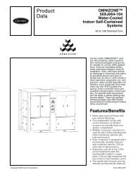
86<br />
The 10 and 15-ton air-cooled Cold Generator<br />
chillers, with Trane direct drive hermetic<br />
scroll compressors, has outstanding standard<br />
features and additional benefits that make<br />
selection, installation, and servicing easy.<br />
Flexibility<br />
Footprint<br />
Central to the design of any project is the<br />
operating envelope of the air-cooled<br />
packaged chiller. With this in mind, Trane<br />
builds the chillers to make the most efficient<br />
use of the available installation space. The<br />
Trane CGA model chillers are extremely<br />
compact. They have the lightest weight, the<br />
smallest footprint, and the lowest silhouette<br />
of any chiller in the industry.<br />
Less Weight<br />
These lightweight models afford less stress<br />
on building supports and greater handling<br />
ease.<br />
Installation<br />
Installation time and effort are reduced when<br />
dealing with a significantly smaller and<br />
lighter unit. In addition, having electrical and<br />
water connections on the same side of the<br />
unit and a single-point main power<br />
connection serves to make installation easier.<br />
The unit arrives at the jobsite fully assembled,<br />
tested, charged and ready to provide chilled<br />
water.<br />
Trane’s 20-60 ton chillers offer the same timetested<br />
and proven control technology that is<br />
applied to the IntelliPak Air Cooled<br />
rooftops.<br />
Superior control makes the IntelliPak a truly<br />
advanced chiller.<br />
UN-PRC001-EN<br />
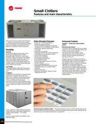
Small Chillers<br />
Features and main characteristics<br />
Other Standard Features<br />
• Trane 3-D Scroll compressors<br />
Advanced motor protection<br />
300 psi waterside evaporator Evaporator<br />
insulation (¾-inch Armaflex II or equivalent)<br />
Evaporator heat tape (thermostat<br />
controlled)<br />
Condenser coil guards<br />
Operation down to 30°F without additional<br />
wind baffles or head pressure control<br />
Loss of flow protection<br />
Packed stock availability<br />
Control Power Transformer<br />
Low ambient lockout<br />
Plain English (Spanish/French) Human<br />
Interface display<br />
Smart Lead/Lag operation<br />
Integrated chilled solution pump control<br />
Selectable process or comfort control<br />
algorithm<br />
External auto/stop<br />
Electronic low ambient damper control<br />
integrated into UCM<br />
Enhanced Controls<br />
IntelliPak Chiller Unit Control Module<br />
(UCM)<br />
Microprocessor Control<br />
The brain of the 20 through 60 ton air-cooled<br />
chiller is its Unit Control Module (UCM). The<br />
UCM is an innovative, modular<br />
microprocessor control design, which<br />
coordinates the actions of the chiller in an<br />
efficient manner, providing stand-alone<br />
operation of the unit.<br />
Access to the unit controls is via a Human<br />
Interface (HI) Panel, a standard component of<br />
the IntelliPak chiller. This panel provides a<br />
high degree of control. Superior monitoring<br />
capability and unmatched diagnostic<br />
information is provided through a 2 line 40<br />
character per line, English language display.<br />
There are no diagnostic “ codes” requiring a<br />
translation key for interpretation. All system<br />
status information and control adjustments<br />
can be made from the onboard Human<br />
Interface Panel.<br />
Remote Human Interface (RHI) — The optional Remote Human Interface (RHI) performs the<br />
same functions as the Human Interface, with the exception of the service mode. The RHI can be<br />
used with up to 4 air-cooled chillers from a single panel.
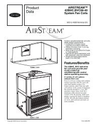
LIQUID CHILLERS<br />
10 - 60 TR<br />
These are products offering easy outdoor installation<br />
thanks to their small size. They have all of the latest<br />
TRANE technological advances : electronic control,<br />
low-speed fans, etc. And these are technologies which<br />
ensure their reliability, operating silence, compactness<br />
and respect for the environment.<br />
FOR WHOM? FOR WHAT?<br />
This range of products is ideal for air-conditioning<br />
applications of a residential type (e.g. villas and<br />
apartments) or for buildings within the service sector<br />
(banks, offices, hotels …) containing more than 3 or 4<br />
rooms requiring air-conditioning.<br />
They can be used together with indoor units such as<br />
console/ceiling, cassette or fan-coil installations.<br />
These products are also widely used for process<br />
applications.<br />
TRANE’S ADVICE<br />
This product is to be recommended for the airconditioning<br />
of a building where :<br />
- there are more than three or four zones<br />
- only one outdoor installation is allowed<br />
- a very low sound level is required.<br />
LIGHT COMMERCIAL RANGE<br />
UN-PRC001-EN<br />
CGA<br />
87
88<br />
UN-PRC001-EN<br />
10 - 60 TR<br />
Air-cooled liquid chiller Axial fan<br />
General Data — 10–60 Ton Units<br />
10 Ton 15 Ton 20Ton 25Ton 30Ton 40Ton 50Ton 60Ton<br />
Model Number<br />
Compressor Data<br />
CGA120 CGA180 CGAF-C20 CGAF-C25 CGAF-C30 CGAF-C40 CGAF-C50 CGAF-C60<br />
Model Scroll Scroll Scroll Scroll Scroll Scroll Scroll Scroll<br />
Quantity 2 2 2 1/1 2 4 2/2 4<br />
Nominal Tons per Compressor<br />
Evaporator<br />
5 7.5 10 10/15 15 10 10/15 15<br />
Nominal Size ( Tons) 10 15 20 25 30 40 50 60<br />
<strong>Water</strong> Storage Capacity (Gallons) ² 1.4 1.5 11.7 10.7 16.3 13.8 21.0 37.8<br />
Min. Flow Rate ( GPM) 12.0 18.0 24 30 36 48 60 72<br />
Max. Flow Rate (GPM) 36.0 54.0 72 90 108 144 180 216<br />
Max EWT At Start-Up — Deg F ³<br />
Condenser<br />
100 100 108 108 108 108 108 108<br />
Nominal Size ( Tons) 10 15 20 25 30 40 50 60<br />
Number of Coils 1 2 1 2 2 2 2 2<br />
Coil Size (ea., Inches) 4 28 x 108 28 x 83 61 x 71 45 x 71/35 x 71 56 x 70 56 x 70 57 x 96 57 x 96<br />
Number o f R ows 2 2 3 3 3 3 4<br />
Subcooler Size (ea., Inches)<br />
Condenser Fans<br />
4 x 10⁸ 4 x 83 10 x 71 14 x 71 9 x 70 9 x 70 9 x 96 9 x 96<br />
Quantity 1 2 2 3 4 4 6 6<br />
Diameter (Inches) 28 26 26 26 26 26 26 26<br />
CFM (Total) 8,120 11,600 15,000 21,650 29,200 29,200 42,300 40,700<br />
Nominal RPM 1100 1100 1140 1140 1140 1140 1140 1140<br />
Tip Speed (Ft/Min) 8060 7490 7750 7750 7750 7750 7750 7750<br />
Motor HP (ea.) 1.0 1/2 1.0 1.0 1.0 1.0 1.0 1.0<br />
Drive Type Direct Direct Direct Direct Direct Direct Direct Direct<br />
Minimum Outdoor Air Temperature Permissible<br />
For Mechanical Cooling¹<br />
Standard Ambient Control Unit (°F) 50 50 30 30 30 30 30 30<br />
Standard Ambient w/Hot Gas Bypass (°F) 60 60 40 40 40 40 40 40<br />
Low Ambient Option (°F) 0 0 0 0 0 0 0 0<br />
Low Ambient Control w/Hot Gas Bypass(°F)<br />
General Unit<br />
15 15 10 10 10 10 10 10<br />
Unload Steps 100-50 100-50 100-50 100-60-40 100-50 100-75-50-25 100-80-60-30 100-75-50-25<br />
No. of Independent Refrig. Circuits 2 2 1 1 1 2 2 2<br />
Refrigerant Charge (lbs. R22/Circuit) 8.25 11.5 40.5 54.0 72.0 38.0 47.0 67.0<br />
Oil Charge (Pints/Circuit) 4.1 7.5 8.0 8.0/14.0 14.0 8.0 8.0/14.0 14.0<br />
*Unloading steps depend upon which compressor is lead compressor.<br />
Notes:<br />
1 Minimum start-up ambient based on unit at minimum step of unloading and a 5 mph wind across the condenser.<br />
2 Includes piping internal to chiller.<br />
3 At 95° F ambient.<br />
4 Does not include subcooling portion of coil.<br />
CGA
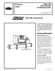
CGA 120 -150<br />
Z<br />
Y<br />
X<br />
CGA 120B CGA 180B<br />
X<br />
Minimum clearance around the perimeter of the unit is 3 feet.<br />
Model and size CGA 120B CGA 180B<br />
Width x depth x height (X x Y x Z) (mm) 1300 x 983 x 964 2240 x 983 x 983<br />
Weight (lb) 529 788<br />
Evaporator Connection Type NPTF NPTF<br />
<strong>Water</strong> Connection diameter (in) 1 1 /2 2<br />
Z<br />
Y<br />
B<br />
C<br />
LIGHT COMMERCIAL RANGE<br />
UN-PRC001-EN<br />
A<br />
B<br />
89
90<br />
Z<br />
Y<br />
Y<br />
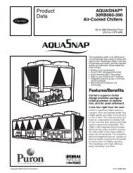
CGAF-C20<br />
Y<br />
A<br />
CGAF-C30 & C40 CGAF-C50 & C60<br />
UN-PRC001-EN<br />
X<br />
X<br />
c<br />
A<br />
a<br />
Z<br />
Model and size CGAF C20 C25 C30 C40 C50 C60<br />
Dimensions Length (X) (mm) 2242 2242 2242 2242 2892 2892<br />
Width (Y) (mm) 1527 1527 2245 2245 2245 2245<br />
Height (Z) (mm) 1588 1727 1854 1854 1854 1854<br />
Clearance (A) (mm) 2438 2438 2438 2438 2438 2438<br />
Clearance (B) (mm) 1067 1067 1067 1067 1067 1067<br />
Operating weight (lbs) 2308 2563 3708 3944 4738 6474<br />
Evaporator Connection type NPS Female Groved Pipe<br />
<strong>Water</strong> connection diameter (Inch) 2 2 2 1 /2 2 1 /2 3 4<br />
Z<br />
A<br />
B<br />
Y<br />
CGAF-C25<br />
X<br />
X<br />
Z
Chilled water terminals<br />
The water terminal range offers an ideal solution for all installation types. Comfort and<br />
silence are the key words for all this units. They can be fitted either on the floor or on the<br />
ceiling, visible or integrated in a false ceiling. Thanks to this solution using a hydraulic<br />
network, the installation becomes easier.<br />
FVC<br />
Capacity (MBH)<br />
04 06 08 10 12 14 16 20<br />
(1) 11 17.2 25.5 29.4 35.7 42.7 50 56.9<br />
CWS<br />
Capacity (MBH)<br />
16 18 20 24 28 32 40<br />
(1) 16 18 20 24 28 32 40<br />
(1) 7/12°C Entering/Leaving water temp., 27/19°C DB/WB air temp. at medium speed.<br />
LIGHT COMMERCIAL RANGE<br />
UN-PRC001-EN<br />
91
92<br />
AQUA STYLUS<br />
CWCS<br />
UN-PRC001-EN<br />
CFEA/CWCS<br />
1 - 5 TR<br />
The only visible parts of an installation are the chilled<br />
water terminals and even they know how to be discrete.<br />
They can be integrated perfectly into the look of the<br />
room through installation in small spaces or false<br />
ceilings.<br />
Hydronic heating is available in CFEA models.<br />
FOR WHOM? FOR WHAT?<br />
Trane offers two configuration which adapt to different<br />
building constraints.<br />
Ceiling installation terminals, installed in false ceilings, an<br />
obvious solution for equipping offices, buildings …<br />
TRANE’S ADVICE<br />
In order to choose the type and quantity of terminals<br />
needed, it is necessary to check carefully the airconditioning<br />
profile.
CWCS 16 - 40<br />
1.3 - 3.3 TR<br />
Chilled water blower unit -Cassette type<br />
X<br />
Dimensions Net weight<br />
(mm) (kg)<br />
Model X Y Z<br />
CWCS 16 840 840 340 26<br />
CWCS 18 840 840 340 26<br />
CWCS 20 840 840 340 29.5<br />
CWCS 24 840 840 340 29.5<br />
CWCS 28 840 840 340 29.5<br />
CWCS 32 840 840 340 32<br />
CWCS 40 840 840 340 32<br />
Front panel 950 950 22 6<br />
LIGHT COMMERCIAL RANGE<br />
UN-PRC001-EN<br />
Main features :<br />
Popularity<br />
One dimension for all sizes<br />
3/4” water connection same as<br />
general fan coil unit<br />
Four-Direction below<br />
Cover maximum area<br />
Low Noise Design<br />
Air-Foil blade centrifugal fan, high<br />
efficiency and quiet. Four walls coil<br />
even the air flow and reduce sound<br />
Auto water pump<br />
Auto drain water detection and pump<br />
out of drain pan<br />
Filter<br />
Easily clean PP Wavy filter<br />
Model CWCS 16 CWCS 18 CWCS 20 CWCS 24 CWCS 28 CWCS 32 CWCS 40<br />
Cooling capacity 1 (MBH) 16 18 20 24 28 32 40<br />
Power supply Single phase 220V / 50Hz; 220 V / 60Hz<br />
Fan Centrifugal air foil fan / 135C thermal cutout<br />
Air flow high CMM 17 21 17.5 21 27 26 34<br />
Standard function Drain pump; InfraRed Remote Control; PP waving filter<br />
<strong>Water</strong><br />
Rated flow LPM 13.5 15.2 16.5 20.9 23.2 27.2 34.9<br />
Pressure drop kg/cm2 0.5 0.6 0.2 0.4 0.6 0.5 0.5<br />
Connection inch 3/4” FPT inlet/outlet<br />
Drain pipe inch 3/4” smooth plastic<br />
1 Capacity test condition high speed; entering air 27 DB / 19.5 EB; chilled water entering 7C, leaving 12C.<br />
Y<br />
Z<br />
93
94<br />
Main features :<br />
Comfort and Reliability<br />
Full Capacity and Energy Savings.<br />
Washable Filter.<br />
Low Maintenance.<br />
Attractive Style.<br />
Effective Air Discharge.<br />
3 Minute Anti-Recycle Timer helps to<br />
preserve the life of system<br />
components.<br />
Optional Electric Heater offers a<br />
better selection of the right unit to<br />
meet your needs.<br />
NEW hydronic heat option.<br />
Power Failure Recovery saves<br />
settings during a power failure and<br />
restarts the system automatically<br />
when power resumes.<br />
Flexibility<br />
Aquastylus’ convertible design<br />
allows for flexibility in installation.<br />
Aquastylus may be installed under<br />
the ceiling, low on the wall, or on the<br />
floor, depending on the space<br />
available in your room.<br />
UN-PRC001-EN<br />
CFEA<br />
1 - 5 TR<br />
AQUASTYLUS<br />
AQUA STYLUS<br />
<strong>Water</strong> Temperature Rise (F)<br />
Unit EWT 10<br />
Size Degree TC SC GPM PD<br />
40 14.5 9.8 2.9 7.9<br />
04 45 11.0 8.3 2.2 4.8<br />
50 7.7 7.0 1.5 2.6<br />
40 22.1 14.5 4.4 8.1<br />
06 45 17.2 12.3 3.4 5.2<br />
50 12.3 10.4 2.5 2.9<br />
40 32.0 20.5 6.4 12.5<br />
08 45 25.5 17.5 5.1 8.3<br />
50 18.6 14.6 3.7 4.7<br />
40 37.5 24.2 7.5 7.1<br />
10 45 29.4 20.5 5.9 4.6<br />
50 21.0 17.1 4.2 2.5<br />
40 44.4 28.0 8.9 9.5<br />
12 45 35.7 23.9 7.1 6.4<br />
50 26.2 19.9 5.2 3.7<br />
40 54.6 36.4 10.9 19.2<br />
14 45 42.7 31.2 8.5 12.3<br />
50 31.2 26.6 6.2 7.0<br />
40 63.5 42.2 12.7 22.9<br />
16 45 50.0 36.3 10.0 14.8<br />
50 36.9 31.0 7.4 8.6<br />
40 71.7 46.4 14.3 13.3<br />
18 45 56.9 39.7 11.4 8.7<br />
50 41.6 33.4 8.3 4.7<br />
TC = Total Capacity, MBh<br />
SC = Sensible Capacity, MBh<br />
GPM = <strong>Water</strong> Flow, Gallon per Minute<br />
PD = <strong>Water</strong> Pressure Drop, ft of water<br />
Notes:<br />
1. Air Entering Coil Conditions are 80/67 in FDB/FWB<br />
2. Cooling capacities are rated at nominal CFM (Hi Fan<br />
Speed)<br />
3. EWT = Entering <strong>Water</strong> Temp (F)<br />
DIMENSIONS (HxWxD)<br />
Uncrated (mm) 627x1085x243 627x1085x268 627x1335x268 627x1585x268 627x1585x268 627x1835x268 627x2085x268 627x2085x268<br />
WEIGHT (kg)<br />
Net (uncrated)<br />
Without Electric Heater 36 37 45 61 61 72 79 84<br />
With Electric Heater 37 38 46 63 63 74 81 87<br />
GENERAL DATA 220-240/1/50<br />
INDOOR UNITS<br />
Model CFEA04CO CFEA06CO CFEA08CO CFEA10CO CFEA12CO CFEA14CO CFEA16CO CFEA20CO<br />
CFEA04CE(*) CFEA06CF(*) CFEA08CB(*) CFEA10CH(*) CFEA12CJ(*) CFEA14CJ(*) CFEA16CK(*) CFEA20CL(*)<br />
<strong>Water</strong> Flow Rate (gpm) 2.4 3.6 4.8 6.0 7.2 8.4 9.6 12.0<br />
Control Valve Yes** Yes** Yes** Yes** Yes** - - - Drain<br />
Connection (in) 3/4 3/4 3/4 3/4 3/4 3/4 3/4 3/4<br />
Air Flow (Hi/Med/Lo)<br />
CFM @ 0.0 in. wg 425/360/300 425/360/300 600/475/375 850/750/650 850/750/650 1,200/1,050/950 1,350/1,100/975 1,350/1,100/975<br />
No Motors (HP) 1(1/20) 1(1/20) 1(1/10) 2(1/20) 2(1/20) 2(1/10) 2(1/10) 2(1/10)<br />
R.L.Amps 0.36 0.42 0.56 2x0.54 2x0.54 2x0.69 2x0.69 2x0.69<br />
L.R.Amps 0.48 0.59 0.67 2x0.89 2x0.89 2x2.28 2x2.28 2x2.28<br />
Electric Heater Data(*)<br />
Heater Rating (kW) 2.0 2.5 3.5 4.0 (2 elem.) 5.0 (2 elem.) 5 (2 elements) 6 (2 elements) 7 (2 elements)<br />
GENERAL DATA 220-240/1/60<br />
INDOOR UNITS<br />
Model CFEA04CO CFEA06CO CFEA08CO CFEA10CO CFEA12CO CFEA14CO CFEA16CO CFEA20CO<br />
CFEA04CE(*) CFEA06CF(*) CFEA08CB(*) CFEA10CH(*) CFEA12CJ(*) CFEA14CJ(*) CFEA16CK(*) CFEA20CL(*)<br />
<strong>Water</strong> Flow Rate (gpm) 2.4 3.6 4.8 6.0 7.2 8.4 9.6 12.0<br />
Control Valve Yes** Yes** Yes** Yes** Yes** - - - Drain<br />
Connection (in)<br />
Air Flow (Hi/Med/Lo)<br />
3/4 3/4 3/4 3/4 3/4 3/4 3/4 3/4<br />
CFM @ 0.0 in. wg 425/360/300 425/360/300 600/475/375 850/750/650 850/750/650 1,200/1,050/950 1,350/1,100/975 1,350/1,100/975<br />
No Motors (HP) 1(1/20) 1(1/15) 1(1/10) 2(1/15) 2(1/15) 2(1/10) 2(1/10) 2(1/10)<br />
Motor Speed (RPM) 1,080 1,150 1,200 1,350 1,350 1,450 1,450 1,450<br />
V/Ph/Hz 220/1/60 220/1/60 220/1/60 220/1/60 220/1/60 220/1/60 220/1/60 220/1/60<br />
R.L.Amps 0.48 0.53 0.67 2x0.65 2x0.65 2x0.73 2x0.73 2x0.73<br />
L.R.Amps<br />
Electric Heater Data(*)<br />
0.53 0.59 0.68 2x0.85 2x0.85 2x1.15 2x1.15 2x1.15<br />
Heater Rating (KW) 2.0 2.5 3.5 4.0 (2 elem.) 5.0 (2 elem.) 5 (2 elements) 6 (2 elements) 7 (2 elements)<br />
(*) Models with electric heaters have an alphabetic lettter in the eight digit,i,e,E,F,B,H,J,K and L.<br />
MCA-Minimum Circuit Ampacity; calculated as follows:125 % of heater R.L.Amps plus the fan motor R.L.Amps.<br />
(**) The control valve is optional for vertical installation only.