Aqu@Logic air cooled water chillers
Aqu@Logic air cooled water chillers
Aqu@Logic air cooled water chillers

You also want an ePaper? Increase the reach of your titles
YUMPU automatically turns print PDFs into web optimized ePapers that Google loves.
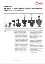
Technical Brochure<br />
TM AQL-A.1GB<br />
Date : May 2003<br />
Supersedes : TM 02 AQL.1UK-A/11.02<br />
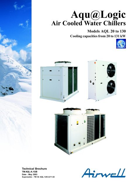
<strong>Aqu@Logic</strong><br />
Air Cooled Water Chillers<br />
Models AQL 20 to 130<br />
Cooling capacities from 20 to 131 kW
Why choose ILTC technology ?<br />
The new range of <strong>Aqu@Logic</strong> <strong>air</strong> <strong>cooled</strong> <strong>water</strong> <strong>chillers</strong> comprises<br />
14 models covering a nominal cooling capacity range of from<br />
20 to 131 kW.<br />
<strong>Aqu@Logic</strong> represents a new generation of innovative <strong>water</strong><br />
<strong>chillers</strong>, integrating components using the very latest technological<br />
advances.<br />
These components provide <strong>Aqu@Logic</strong> <strong>air</strong> <strong>cooled</strong> <strong>water</strong> <strong>chillers</strong><br />
with considerable advantages in terms of compact design and<br />
improved efficiency and reliability.<br />
All <strong>Aqu@Logic</strong> <strong>air</strong> <strong>cooled</strong> <strong>water</strong> <strong>chillers</strong> are equipped with<br />
ILTC - Intelligent Liquid Technology Control providing<br />
Features and benefits<br />
A maximum of technology<br />
The new generation of <strong>Aqu@Logic</strong> <strong>air</strong> <strong>cooled</strong> <strong>water</strong> <strong>chillers</strong><br />
integrates high technology components :<br />
- Scroll compressors.<br />
- Brazed stainless steel plate heat exchangers.<br />
- High efficiency axial fans with external rotors.<br />
- Microprocessor based ILTC - Intelligent Liquid Technology<br />
Control.<br />
- HFC 407-C refrigerant fluid : non-polluting and protecting the<br />
ozone layer.<br />
Quick and easy installation at minimal cost<br />
- Compact units taking up the strict minimum of ground surface<br />
area, for easy installation.<br />
- “Plug and Play” design with an integrated hydraulic module for<br />
minimising installation costs.<br />
- Perfect accessibility : easy access to all components, thanks<br />
to panels removable by a quarter turn key or screw, thus<br />
significantly reducing unit maintenance times.<br />
Increased performance<br />
- Optimal efficiency, thanks to the use of Scroll compressors<br />
with a high Coefficient Of Performance (COP), fitted in tandem<br />
on all models in the range.<br />
General specifications<br />
Cabinet and structure<br />
- Made of galvanised steel panels coated with oven-baked epoxy<br />
paint. Colour : RAL 9001.<br />
- For access to all components, the panels are removable by<br />
just releasing quarter turn locks or screws.<br />
Compressors<br />
- Hermetically sealed, high output Scroll type compressors with<br />
a high Coefficient Of Performance (COP).<br />
- All models in the range equipped with compressors fitted in<br />
tandem for reducing both starting current draw and power<br />
absorbed under partial load conditions.<br />
Page 2<br />
optimised control across the unit’s entire operating range.<br />
As standard equipment, each unit has two compressors, fitted in<br />
tandem, for adapting to partial system loads.<br />
Pressure and temperature sensors provide data to the electronic<br />
control system for taking account of the prevailing operating<br />
parameters in order to optimise system performance.<br />
This intelligent control system enables <strong>water</strong> temperature to be<br />
maintained within the required range, whilst only using a small<br />
volume of <strong>water</strong> (2.5 l/kW) and thus eliminating, for the majority of<br />
comfort <strong>air</strong> conditioning applications, the need for a buffer <strong>water</strong><br />
tank.<br />
- Guaranteed for operating at outdoor temperatures between<br />
-10 °C and +46 °C inclusive, thanks to the automatic condensing<br />
pressure management system supplied as standard equipment<br />
on all models in the range.<br />
- Silent running, thanks to the dual-speed fan, selected for being<br />
one of the quietest fans currently available on the market, and<br />
thanks to the use of particularly quiet, low vibration, Scroll<br />
compressors.<br />
Built to last<br />
- ILTC - Intelligent Liquid Technology Control automatically<br />
manages the balancing of the compressors’ running times,<br />
thus enabling their service life to be extended.<br />
- Sealed refrigerant circuit : all the refrigerant components and<br />
pipe work are brazed, thus eliminating any risks of leakage.<br />
Pressure transducers replace the HP and LP pressostats,<br />
along with their capillary tubes (principal source of leaks).<br />
Energy savings all year round<br />
Thanks to ILTC - Intelligent Liquid Technology Control :<br />
- Providing intelligent management of the compressors’ running<br />
times.<br />
- In the majority of cases, obviating the need for a buffer tank for<br />
comfort <strong>air</strong> conditioning applications.<br />
- Continuously monitoring and managing all the machine’s<br />
operating parameters.<br />
- Excellent acoustic performance with extremely quiet operation<br />
and minimal vibration.<br />
- Robust and reliable Scroll compressor technology :<br />
Few moving parts (only 3), high tolerance to liquid pressure<br />
shocks, low starting torque, protection against excessive<br />
discharge temperatures.<br />
- Compressor motor <strong>cooled</strong> by intake gasses and equipped<br />
with automatic reset internal high temperature protection.<br />
- All compressors are mounted on anti-vibration pads in order to<br />
minimise noise and vibration transmission. Furthermore, they<br />
are supplied with soundproof jackets.
General specifications (continued)<br />
Evaporator<br />
- Direct expansion type, made of brazed stainless steel plates.<br />
- The evaporator is surrounded by an electrical heating<br />
resistance and insulated with cellular polyurethane foam to<br />
provide anti-freeze protection down to an ambient temperature<br />
of - 20 °C.<br />
Air condenser<br />
- Comprising a heat exchanger coil equipped with aluminium fins<br />
mechanically crimped on to copper tubes.<br />
Fan motor assembly<br />
- Helicoidal type fans with direct drive by a dual speed motor<br />
(Protection Index : IP 54), equipped with automatic reset internal<br />
high temperature protection.<br />
- Two 610 mm diameter horizontal flow fans on models 20 to 35,<br />
one 800 mm diameter vertical flow fan on models 40 to 80 and<br />
two 800 mm diameter vertical flow fans on models 90 to 130.<br />
Each fan is equipped with a fan blade protection grille.<br />
Refrigerant circuit<br />
The refrigerant circuit comprises all the required components such<br />
as filter-dryer, sight glass with moisture indicator and thermostatic<br />
expansion valve. It also comprises high and low pressure sensors,<br />
as well as sensors for inlet and outlet <strong>water</strong> temperatures and a<br />
discharge temperature sensor.<br />
To facilitate maintenance operations, the low and high pressure<br />
sections of the refrigerant circuit are equipped with pressure tapping<br />
points.<br />
All the refrigerant components and pipe work are brazed, thus<br />
eliminating any risks of leakage and ensuring total, long lasting<br />
circuit tightness.<br />
Pressure transducers replace the HP (High Pressure) and LP<br />
(Low Pressure) pressostats, along with their capillary tubes<br />
(principal source of leaks).<br />
The refrigerant circuit is optimised to operate with HFC 407C<br />
refrigerant fluid.<br />
Electrical panel<br />
Access to the electrical panel is possible after having taken off the<br />
panels, removable by just releasing quarter turn locks or screws.<br />
The electrical panel of models 90 to 130 rotates to allow an easy<br />
access for inspection inside the unit.<br />
On models 20 to 35, the following equipment is mounted on the<br />
power circuit side of the electrical panel : a power supply connection<br />
terminal block - 400 V / 3 Ph / 50 Hz + Neutral, a main switch,<br />
contactors and thermal relays for the compressors and the<br />
hydraulic pump (if fitted). On the control circuit side of the panel,<br />
the ILTC - Intelligent Liquid Technology Control electronic<br />
circuit board with its 230 V single phase power supply is mounted.<br />
On models 40 to 130, the following equipment is mounted on the<br />
power circuit side of the electrical panel : a power supply connection<br />
terminal block - 400 V / 3 Ph / 50 Hz + Neutral (models 40 to 80) or<br />
400 V / 3 Ph / 50 Hz (models 90 to 130), a main switch, a main<br />
terminal block, a distribution terminal block, the compressors<br />
contactors, the thermal relays and contactors for the fans, and<br />
the hydraulic pump (if fitted). On the control circuit side of the<br />
panel, the ILTC - Intelligent Liquid Technology Control<br />
electronic circuit board with its 230 V single phase power supply is<br />
mounted.<br />
Integrated hydraulic module<br />
An integrated hydraulic module is available for all <strong>Aqu@Logic</strong> <strong>air</strong><br />
<strong>cooled</strong> <strong>water</strong> <strong>chillers</strong>, offering savings in installation times and<br />
reducing installation costs. Each hydraulic module comprises the<br />
following components :<br />
On models 20 to 35 : Automatic <strong>air</strong> bleed valve, differential<br />
pressostat, drain cock, expansion tank, safety valve, pressure<br />
gauge, hydraulic pump and <strong>water</strong> filter (supplied as a kit - not<br />
fitted).<br />
On models 40 to 130 : Automatic <strong>air</strong> bleed valve, <strong>water</strong> flow<br />
adjustment valve, <strong>water</strong> flow switch, drain cock, expansion tank,<br />
safety valve, pressure gauge, hydraulic pump and fitted <strong>water</strong><br />
filter.<br />
As standard, all pumps produce available pressure higher than<br />
100 kPa. A pump producing available pressure higher than<br />
150 kPa can be supplied on request.<br />
Other standard equipment :<br />
Anti-vibration pads kit : The 20 to 130 models are supplied with<br />
rubber anti-vibration pads as standard, to be fitted on site by the<br />
installer.<br />
Water flow switch or differential pressostat : For <strong>Aqu@Logic</strong><br />
units without an integrated hydraulic module, a factory-fitted<br />
differential pressostat (for models 20 to 35) and a field-installed<br />
paddle type <strong>water</strong> flow switch (for models 40 to 130) are supplied<br />
as standard.<br />
Water filter : Supplied loose.<br />
Coil protection grilles : <strong>Aqu@Logic</strong> units are supplied with<br />
heat exchanger coil protection grilles as standard.<br />
Accessories and options :<br />
Anti-vibration pads kit : For models 40 to 130. Visible spring<br />
anti-vibration pads for the unit and the ground mounting holes. For<br />
on site fitting by the installer.<br />
Condenser coil protective coating :<br />
- aluminium fins with hydrophilic coating,<br />
- aluminium fins with polyurethane coating.<br />
High pressure fans : For models 40 to 120 with ductable fans<br />
providing external static pressure of 80 Pa (models 40 to 60) and<br />
100 Pa (models 70 to 120).<br />
400 V / 230 V transformer : For models 40 to 80 with electrical<br />
supply without neutral.<br />
Buffer tank kit : For <strong>air</strong> conditioning applications where it is not<br />
possible to comply with the <strong>water</strong> volume ratio of 2.5 l / kW. This kit<br />
comprises a factory-fitted module, mounted under the unit, and<br />
supplied with the external hydraulic pipe work to be fitted on site.<br />
The hydraulic module is fully encased in galvanised steel panels,<br />
painted the same colour as the unit, and comprises a buffer tank,<br />
fully insulated with 30 kg / m3 density cellular polyurethane foam.<br />
As standard, the buffer tank is equipped with anti-freeze protection<br />
in the form of an immersion heater.<br />
Remote control terminal : Hard-wired control enabling the unit’s<br />
Start / Stop functions to be controlled remotely.<br />
Phase monitor : Factory-fitted option enabling the compressor’s<br />
rotational direction to be checked and to stop the unit if the minimum<br />
voltage threshold is reached.<br />
Low ambient kit (-18 °C) : Factory-fitted option available for<br />
models 40 to 130.<br />
Chiller sequencer : Supplied loose, it allows a control up to 4<br />
units.<br />
HP and LP manometers : Supplied loose.<br />
Water isolating valves : Supplied loose.<br />
Packaging : Sea worth or wooden crate.<br />
Page 3
ILTC system<br />
Display<br />
The ILTC - Intelligent Liquid Technology Control system is an<br />
intelligent digital control system designed especially for optimising<br />
the operation of <strong>Aqu@Logic</strong> units and maintaining conditions of<br />
maximum comfort.<br />
Before each start-up, the ILTC - Intelligent Liquid Technology<br />
Control system runs through a complete machine checklist. It<br />
continuously monitors and manages all the machine’s operating<br />
parameters and safety devices. It precisely manages the running<br />
of the compressors and fans in order to optimise energy<br />
consumption. It also controls the operation of the <strong>water</strong> circulation<br />
pump.<br />
User interface :<br />
The ILTC - Intelligent Liquid Technology Control system has<br />
an easy-to-use user interface comprising a 4 character, 7 segment<br />
red colour LED display, 3 keys below the display for access to the<br />
different menus : the right key is reserved for the TEST mode, the<br />
centre key for scrolling up and down the menus, and the left key<br />
for selecting a parameter and displaying its value.<br />
Six main menus are available for accessing all the machine’s<br />
controls :<br />
- Parameters.<br />
- Temperature sensors and pressure transducers.<br />
- Active safety alarms.<br />
- Compressors’ operating times.<br />
- Safety alarms history (last 10 alarms).<br />
- Machine operating status.<br />
Using these 6 menus enables a machine status diagnosis to be<br />
performed as well as checking all the <strong>Aqu@Logic</strong> unit’s parameter<br />
settings.<br />
ILTC - Intelligent Liquid Technology Control system description<br />
- Intelligent regulation with return <strong>water</strong> temperature control and<br />
outlet <strong>water</strong> temperature measurement.<br />
- The selection and operating time duration of each compressor<br />
is automatically managed by the ILTC - Intelligent Liquid<br />
Technology Control system, with the possibility of balancing<br />
the compressors’ operating times. When they are operating,<br />
the compressors are monitored constantly to improve their<br />
operating cycle and to avoid any excessive cycling. Thus,<br />
these <strong>Aqu@Logic</strong> units can operate in complete safety with a<br />
low volume of <strong>water</strong> in the installation, enabling the buffer tank<br />
to be dispensed with in the majority of comfort <strong>air</strong> conditioning<br />
applications.<br />
- The ILTC - Intelligent Liquid Technology Control system is<br />
intelligent, i.e. it continuously adapts to changes in the installation’s<br />
thermal load by optimising running times with the selection of<br />
one or both compressors, in relation to actual demand.<br />
Page 4<br />
- Condensing pressure control is included as standard, thus<br />
enabling all <strong>Aqu@Logic</strong> units to operate between - 10 °C and<br />
+ 46 °C. Condensing pressure control is provided by an<br />
algorithm, automatically managing the fan speeds operation. In<br />
partial load or low ambient outdoor temperature conditions, the<br />
fan is switched automatically to low speed running, offering a<br />
significant reduction in noise levels.<br />
- As standard, the ILTC - Intelligent Liquid Technology Control<br />
system offers the possibility of selecting a "Night-time running<br />
mode" function.<br />
- Water pump control with 2 possible operating modes:<br />
Continuous operation in ON / OFF mode or operating only in<br />
ON mode.<br />
When the “Night-time Running” mode is activated, four<br />
operating modes are available :<br />
1st mode : Selected to change the set temperature for energy<br />
savings when the building is unoccupied.<br />
2nd mode : Selected to enable the set temperature to be lowered.<br />
3rd mode : Selected to change the set condensing pressure<br />
values, to force the fan to run at low speed and to obtain silent<br />
running during the night.<br />
4th mode : Selected for applying a combination of modes 1 and 3.<br />
- In addition, as a standard feature, the ILTC - Intelligent Liquid<br />
Technology Control system offers the possibility of<br />
automatically compensating the set temperature value in relation<br />
to changes in the outdoor <strong>air</strong> temperature.<br />
Safety<br />
The system measures changes in parameters (temperatures,<br />
pressures,…) and reacts to keep the compressor within its<br />
operating range.<br />
If, despite everything, a parameter exceeds its limit, a warning<br />
message is generated and the machine is shut down.<br />
The following faults cause the machine to shut down :<br />
- Suction pressure too low.<br />
- Discharge pressure too high.<br />
- Outlet <strong>water</strong> temperature below authorised limits.<br />
- Discharge temperature too high.<br />
- Compressor(s), fan(s), <strong>water</strong> pump overload.<br />
- Compressor direction of rotation reversed.<br />
- Temperature sensors and pressure transducers fault.<br />
- Evaporator anti-freeze protection.<br />
The ILTC - Intelligent Liquid Technology Control system has<br />
33 alarm codes enabling the origin of breakdowns to be determined.<br />
The following safety devices protect the units :<br />
- Water flow switch or differential pressostat.<br />
- Fan high speed and low speed thermal relays.<br />
- N° 1 and N° 2 compressor internal thermal protection.<br />
- Hydraulic pump thermal relay.<br />
- HP safety pressostat.<br />
Remote unit management<br />
The system enables the following functions to be operated, by<br />
means of dry contacts :<br />
- Remote ON / OFF switch.<br />
- Remote Day / Night running mode switch.<br />
- Loadshedding mode.<br />
- Remote alarm reading.
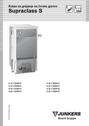
Refrigerant flow diagrams<br />
Models 20 to 80<br />
2<br />
COMPONENTS<br />
1 C1/C2 compressors<br />
2 Condenser<br />
3 Filter - dryer<br />
4 Sight glass with moisture indicator<br />
5 Expansion valve<br />
6 Plate heat exchanger<br />
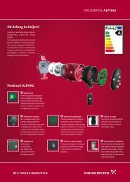
Models 90 to 130<br />
2<br />
COMPONENTS<br />
1 C1/C2 compressors<br />
2 Condenser<br />
3 Filter - dryer<br />
4 Sight glass with moisture indicator<br />
5 Expansion valve<br />
6 Plate heat exchanger<br />
7 Muffler<br />
FH1 FPC CPT DIS<br />
1<br />
C1<br />
FPE<br />
P P P T<br />
P<br />
3<br />
FH1 FPC CPT DIS<br />
1<br />
C1<br />
FPE EPT<br />
P P P T<br />
P P<br />
7<br />
3<br />
C2<br />
4<br />
C2<br />
4<br />
EPT<br />
P<br />
Control and safety components<br />
CPT Condenser pressure tapping point<br />
DIS Discharge temperature sensor<br />
EPT Evaporator pressure tapping point<br />
EWT Inlet <strong>water</strong> temperature sensor<br />
FH1 High pressure safety pressostat<br />
FPC Condenser pressure transducer<br />
FPE Evaporator pressure transducer<br />
LWT Outlet <strong>water</strong> temperature sensor<br />
The low pressure refrigerant fluid flows into the evaporator, it<br />
evaporates and is then superheated by absorbing heat from the<br />
passing of "chilled" <strong>water</strong> through the evaporator.<br />
The low pressure vapour is sucked in by the compressor to be<br />
compressed at high pressure and high temperature.<br />
5<br />
5<br />
6<br />
6<br />
P<br />
T<br />
LWT<br />
P<br />
T<br />
LWT<br />
FS<br />
FS<br />
EWT<br />
T<br />
Water inlet/outlet<br />
EWT<br />
T<br />
Water inlet/outlet<br />
The high pressure, superheated refrigerant flows into the<br />
condenser where the heat is rejected into the ambient <strong>air</strong>.<br />
Then the condensed, sub<strong>cooled</strong> refrigerant fluid flows into the<br />
expansion valve, where the pressure and temperature is lowered<br />
before the fluid is returned to the evaporator.<br />
Page 5
Selection guide<br />
The following information is required for selecting the appropriate<br />
model :<br />
1. Required cooling capacity in kW.<br />
2. Chilled <strong>water</strong> inlet / outlet temperatures.<br />
3. Outdoor <strong>air</strong> temperature.<br />
4. Altitude (in metres) above sea level.<br />
N.B. : the cooling capacity is determined by the following formula :<br />
Cooling capacity (kW) = [Water flow (l/h) x Delta T (K)] / 860<br />
Selection example<br />
Data :<br />
- Required cooling capacity : 21 kW.<br />
Operating temperature ranges<br />
Page 6<br />
Ambient <strong>air</strong> temperature (°C)<br />
Standard unit operating range with glycol<br />
- Outlet <strong>water</strong> temperature : 6 °C.<br />
- Inlet <strong>water</strong> temperature : 11 °C.<br />
- Outdoor <strong>air</strong> temperature : 30 °C.<br />
- Altitude : 0 m.<br />
In the performance table on Page 12, the model 20 will supply<br />
cooling capacity of 21.5 kW with a power consumption of 6.8 kW.<br />
Comment : Interpolation is authorised for conditions<br />
differing from those indicated in the performance table.<br />
However, extrapolation is prohibited.<br />
The <strong>water</strong> flow will be equal to (21.5 kW / 5 K) x 860 = 3698 l/h.<br />
Determine the unit’s available pressure from the curves on<br />
pages 14 and 15 or the evaporator <strong>water</strong> pressure drops from the<br />
curves on pages 16 and 17.<br />
Standard unit<br />
operating range<br />
Outlet <strong>water</strong> temperature (°C)
Selection guide (continued)<br />
Operating limits (*) Altitude correction factors<br />
Temperature min. max<br />
Inlet <strong>water</strong> at start-up °C 10 30<br />
Inlet <strong>water</strong> during running °C 10 23<br />
Outlet <strong>water</strong> during running (without glycol) °C 5 18<br />
Water temperature difference K 3 7<br />
Working pressure bar - 3<br />
Air<br />
(*) For chilled <strong>water</strong> ∆T = 5K.<br />
°C -10 46<br />
Chilled <strong>water</strong> inlet/outlet temperature<br />
correction factors<br />
Chilled <strong>water</strong><br />
in/out temp. (°C)<br />
Cooling capacity<br />
correction factors<br />
Power<br />
consumption<br />
correction factors<br />
14 / 7 (∆T=7 K) 0.970 0.990<br />
12 / 7 (∆T=5 K) 1.000 1.000<br />
10 / 7 (∆T=3 K) 1.030 1.010<br />
Condenser fouling factors<br />
Fouling factors<br />
(m 2 .°C/kW)<br />
Hydraulic circuit <strong>water</strong> volume<br />
Cooling capacity<br />
correction factors<br />
Minimum volume for comfort <strong>air</strong> conditioning applications<br />
Altitude Cooling capacity Power consumption<br />
(m) correction factors correction factors<br />
0 1.000 1.000<br />
600 0.987 1.010<br />
1200 0.973 1.020<br />
1800 0.958 1.029<br />
2400 0.943 1.038<br />
Evaporator fouling factors<br />
Fouling factors<br />
(m 2 .°C/kW)<br />
Cooling capacity<br />
correction factors<br />
(*) Volumes calculated for Eurovent operating conditions (<strong>air</strong> : 35 °C, <strong>water</strong> 12/7 °C) with a 2.5 l/kW ratio. For other nominal operating<br />
conditions, recalculate the minimum volume by multiplying the corresponding cooling capacity by the 2.5l/kW ratio.<br />
If the minimum volume requirement can not be met, an additional buffer tank must be included in the installation.<br />
Maximum volume (*) in litres for comfort <strong>air</strong> conditioning applications<br />
Sizes 20 to 35 40 to 80 90 to 130<br />
Water 300 600 1500<br />
10% glycol solution 225 450 1200<br />
15% glycol solution 215 425 1100<br />
20% glycol solution 200 400 1000<br />
25% glycol solution 185 375 930<br />
30% glycol solution 175 350 860<br />
35% glycol solution 150 300 800<br />
Power<br />
consumption<br />
correction factors<br />
0.044 1.000 1.000<br />
0.088 0.987 0.995<br />
0.176 0.964 0.985<br />
0.352 0.915 0.962<br />
Power<br />
consumption<br />
correction factors<br />
0.044 1.000 1.000<br />
0.088 0.987 1.023<br />
0.176 0.955 1.068<br />
0.352 0.910 1.135<br />
Sizes 20 25 30 35 40 50 60 70 80 90 100 110 120 130<br />
Volume* (litres) 54 65 75 86 105 120 145 170 190 220 245 280 310 330<br />
(*) Limit linked to the unit’s expansion tank volume. In the case of an installation with a <strong>water</strong> volume greater than the values stated in the<br />
above table, an additional buffer tank must be included in the installation.<br />
Page 7
Technical characteristics - HFC 407C<br />
AQL sizes 20 25 30 35 40 50 60 70 80<br />
Power supply (V / Ph / Hz)<br />
400/3+N/50<br />
Cooling capacity * kW 21.5 26.0 29.9 34.2 42.0 46.5 56.9 67.3 75.4<br />
Total power consumption with pump kW 8.4 10.0 11.4 12.2 16.1 19.4 23.9 28.1 30.7<br />
Total power consumption kW 7.6 9.2 10.6 11.4 15.4 18.7 22.8 27.0 29.6<br />
COP 3.0 3.0 3.0 2.9 2.9 2.6 2.7 2.7 2.7<br />
Refrigerant charge kg 6.2 6.2 6.2 7.6 9 9 10 11 16<br />
Lw sound power levels<br />
Compressors<br />
dB(A) 75 76 76 77 82 82 84 87 87<br />
Type<br />
Scroll - Hermetically sealed<br />
Quantity 2 2 2 2 2 2 2 2 2<br />
Capacity reduction stages 2 2 2 2 2 2 2 2 2<br />
Minimum capacity % 50 50 50 50 45 36 36 45 50<br />
Safety pressostat<br />
HP (fixed set point)<br />
LP transducer<br />
HP transducer<br />
Evaporator<br />
Type<br />
Maximum pressure refrigerant side bar<br />
Maximum pressure <strong>water</strong> side bar<br />
Safety<br />
Anti-freeze protection heating resistance 1 1 1 1 1 1 1 1 1<br />
Water volume<br />
Condenser<br />
litres 1.67 2.2 2.44 2.44 3.44 4.33 5.33 6.33 7.10<br />
Type<br />
Fans<br />
Quantity 2 2 2 2 1 1 1 1 1<br />
Fan diameter mm 610 610 610 610 800 800 800 800 800<br />
Speed (High/Low) rpm 640/500 640/500 640/500 640/500 700/500 700/500 700/500 900/520 900/520<br />
Max. <strong>air</strong> flow (HS) m3 3/8" copper tube - Louvred aluminium fins<br />
Water connections<br />
/h 11200 11200 11200 11200 15500 15500 15500 21000 21000<br />
Type<br />
Gas - Threaded<br />
Gas - Threaded<br />
Diameter inches 1"1/2 1"1/2 1"1/2 1"1/2 2" 2" 2" 2" 2"<br />
Expansion tank litres<br />
Filter<br />
Safety valve calibration bar 3 3 3 3 3 3 3 3 3<br />
Water circulation pump<br />
Type<br />
Material<br />
Protection index<br />
Three phase motor<br />
Weight<br />
With pump kg 280 290 300 305 500 550 570 600 620<br />
Without pump<br />
Dimensions<br />
kg 265 275 285 290 480 530 550 580 600<br />
Length mm 1477 1477 1477 1477 1737 1737 2168 2168 2168<br />
Width mm 516 516 516 516 1201 1201 1201 1201 1201<br />
Height mm 1607 1607 1607 1607 1634 1634 1634 1634 1634<br />
Page 8<br />
Brazed stainless steel plates<br />
30<br />
10<br />
Differential pressostat Water flow switch<br />
5 12<br />
1" 1/2, supplied loose 2", supplied fitted<br />
Single speed centrifugal pump<br />
AISI 304 stainless steel Composite<br />
IP54 IP54<br />
Class F Class F<br />
* Values based on chilled <strong>water</strong> inlet / outlet temperatures of 12 / 7° C and an ambient <strong>air</strong> temperature of 35° C.
Technical characteristics - HFC 407C (continued)<br />
AQL sizes 90 100 110 120 130<br />
Power supply (V / Ph / Hz)<br />
Cooling capacity * kW 86.4 98.0 112.0 122.2 131.0<br />
Compressor power consumption kW 31.0 35.7 39.8 44.4 43.0<br />
Total power consumption kW 43.2 48.4 54.9 60.1 62.0<br />
COP 2.8 2.7 2.8 2.8 3.0<br />
Refrigerant charge kg 24 28 30 34 34<br />
Lw sound power levels<br />
Compressors<br />
dB(A) 86 86 87 87 90<br />
Type<br />
Quantity 2 2 2 2 2<br />
Capacity reduction stages 2 2 2 2 2<br />
Minimum capacity % 45 / 55 40 / 60 45 / 55 50 / 50 50 / 50<br />
Safety pressostat<br />
Evaporator<br />
Type<br />
Maximum pressure refrigerant side bar<br />
Maximum pressure <strong>water</strong> side bar<br />
Safety<br />
Anti-freeze protection heating resistance<br />
Fans<br />
W 70 70 70 70 70<br />
Quantity 2 2 2 2 2<br />
Fan diameter mm 800 800 800 800 800<br />
Speed (High/Low) rpm 700/500 700/500 700/500 700/500 900/520<br />
Max. <strong>air</strong> flow (HS) m3 400/3/50<br />
Scroll - Hermetically sealed<br />
HP (fixed set point)<br />
LP transducer<br />
HP transducer<br />
Brazed stainless steel plates<br />
30<br />
10<br />
Water flow switch<br />
Water connections<br />
/h 30000 30000 30000 30000 40000<br />
Type<br />
Gas - Male threaded<br />
Diameter<br />
Weight<br />
inches 2" 2" 2" 2" 2"<br />
Shipping weight<br />
Dimensions<br />
kg 1000 1050 1100 1100 1120<br />
Length mm 2523 2523 2865 2865 2865<br />
Width mm 1201 1201 1201 1201 1201<br />
Height mm 1634 1634 1634 1634 1634<br />
* Values based on chilled <strong>water</strong> inlet / outlet temperatures of 12 / 7° C and an ambient <strong>air</strong> temperature of 35° C.<br />
Page 9
Technical characteristics - HFC 407C (continued)<br />
Protection devices<br />
AQL sizes 20 25 30 35 40 50 60 70 80 90 100 110 120 130<br />
Fan thermal protection<br />
yes<br />
Compressors thermal protection<br />
yes<br />
Ancillaries / Fan circuit breakers<br />
yes<br />
Compressors circuit breakers<br />
yes<br />
Water pressure differential pressostat<br />
yes<br />
Water flow switch<br />
yes<br />
HP pressostat<br />
yes<br />
Evaporator anti-freeze protection<br />
yes<br />
HP transducer<br />
yes<br />
LP transducer<br />
yes<br />
Lw (A) sound power levels<br />
AQL<br />
Frequency in octave band (Hz)<br />
Global<br />
sizes 63 125 250 500 1000 2000 4000 8000 dBA<br />
20 55 63 67 73 64 62 60 57 75<br />
25 56 64 68 74 65 63 61 58 76<br />
30 56 64 68 74 65 63 61 58 76<br />
35 57 65 69 75 66 64 62 59 77<br />
40 62 70 74 80 74 70 67 64 82<br />
50 62 70 74 80 74 70 67 64 82<br />
60 63 71 75 82 75 71 68 65 84<br />
70 67 75 79 84 75 74 72 69 87<br />
80 67 80 84 84 75 79 77 74 87<br />
90 80 79 73 79 80 76 71 61 86<br />
100 80 79 73 79 80 76 71 61 86<br />
110 81 81 74 80 80 78 73 61 87<br />
120 81 81 74 80 80 78 73 61 87<br />
130 86 86 79 85 85 83 83 67 90<br />
Lp (A) sound pressure levels<br />
AQL<br />
Frequency in octave band (Hz)<br />
Global<br />
sizes 63 125 250 500 1000 2000 4000 8000 dBA<br />
20 39 47 51 57 48 46 44 41 59<br />
25 40 48 52 58 49 47 45 42 60<br />
30 40 48 52 58 49 47 45 42 60<br />
35 41 49 53 59 50 48 46 43 61<br />
40 46 54 58 64 58 54 51 48 65<br />
50 46 54 58 64 58 54 51 48 65<br />
60 47 55 59 65 58 54 52 48 67<br />
70 51 59 63 68 59 58 56 53 70<br />
80 51 64 68 68 59 63 61 58 70<br />
90 63 62 56 62 63 59 54 44 69<br />
100 63 62 56 62 63 59 54 44 69<br />
110 63 63 56 61 61 60 55 43 69<br />
120 63 63 56 61 61 60 55 43 69<br />
130 68 68 61 67 67 65 65 49 72<br />
Sound pressure levels indicated at 1 m from the unit in a free field condition.<br />
Page 10
Electrical characteristics - HFC 407C<br />
Unit with hydraulic module<br />
AQL sizes 20 25 30 35 40 50 60 70 80 90 100 110 120 130<br />
Supply voltage (V / Ph / Hz)<br />
Permissible voltage<br />
Nominal power consumption kW 8.4 10.0 11.4 13.5 16.1 19.4 23.9 28.1 30.7 34.7 39.4 43.8 48.4 48.8<br />
Maximum power consumption kW 10.0 14.2 16.2 16.6 20.1 25.3 30.0 36.1 38.9 44.7 49.9 56.7 61.9 63.8<br />
Nominal current A 18.3 21.5 22.9 27.7 31.0 36.0 42.9 49.5 53.3 64.3 71.4 79.6 86.7 89.9<br />
Maximum current A 21.3 29.3 31.3 33.3 38.5 46.5 53.5 63.1 67.1 76.3 85.0 95.4 104.1 107.3<br />
Maximum starting current A 65 83 92 121 145 189 222 231 235 253 308 318 327 330<br />
External fuse A 25 32 32 40 50 50 63 63 80 100 100 125 125 125<br />
Cable section (100 m max.) mm 2 400 / 3+N / 50<br />
400 / 3 / 50<br />
380-420<br />
380-420<br />
6 10 10 10 16 16 25 25 25 35 35 50 50 50<br />
Unit without hydraulic module<br />
AQL sizes 20 25 30 35 40 50 60 70 80 90 100 110 120 130<br />
Supply voltage (V / Ph / Hz)<br />
Permissible voltage<br />
Nominal power consumption kW 7.6 9.2 10.6 12.8 15.4 18.7 22.8 27.0 29.6 33.2 37.9 42.0 46.6 47.0<br />
Maximum power consumption kW 9.2 13.3 15.4 15.9 19.4 24.5 28.9 35.0 37.8 43.2 48.4 54.9 60.1 62.0<br />
Nominal current A 16.6 19.8 21.2 26.0 28.9 33.9 39.8 46.4 50.2 60.5 67.6 74.7 81.8 85.0<br />
Maximum current A 19.6 27.6 29.6 31.6 36.4 44.4 50.4 60.0 64.0 72.5 81.2 90.5 99.2 102.4<br />
Maximum starting current A 64 82 91 120 142 186 218 228 232 249 304 313 322 325<br />
External fuse A 25 32 32 40 50 50 63 63 80 100 100 125 125 125<br />
Cable section (100 m max.) mm 2 400 / 3+N / 50<br />
400 / 3 / 50<br />
380-420<br />
380-420<br />
6 10 10 10 16 16 25 25 25 35 35 50 50 50<br />
Compressors<br />
AQL sizes 20 25 30 35 40 50 60<br />
Nominal power consumption kW 3.5 + 3.5 4.3 + 4.3 5.0 + 5.0 6.1 + 6.1 7.9 + 6.4 11.2 + 6.4 13.8 + 7.6<br />
Maximum power consumption kW 4 + 4 6 + 6 7 + 7 8 + 8 10 + 8 15 + 8 18 + 10<br />
Nominal current A 6.5 + 6.5 8.1 + 8.1 8.8 + 8.8 11.2 + 11.2 14.3 + 12.2 19.3 + 12.2 23.1 + 14.3<br />
Maximum current A 8 + 8 12 + 12 13 + 13 14 + 14 18 + 16 26 + 16 30 + 18<br />
Crankcase heater W 70 + 70 70 + 70 70 + 70 70 + 70 70 + 70 70 + 70 70 + 70<br />
AQL sizes 70 80 90 100 110 120 130<br />
Nominal power consumption kW 13.8 + 11.2 13.8 + 13.8 17.6 + 13.4 22 + 13.7 23.9 + 15.9 22.2 + 22.2 21.5 + 21.5<br />
Maximum power consumption kW 18 + 15 18 + 18 24 + 17 29 + 17 29 + 24 29 + 29 29 + 29<br />
Nominal current A 23.1 + 19.3 23.1 + 23.1 31.4 + 24.3 38.5 + 24.3 38.5 + 31.4 38.5 + 38.5 38.5 + 38.5<br />
Maximum current A 30 + 26 30 + 30 38.5 + 29 47 + 29 47 + 38.5 47 + 47 47 + 47<br />
Crankcase heater W 70 + 70 70 + 70 130 + 75 130 + 75 130 + 130 130 + 130 130 + 130<br />
Standard condenser fans<br />
AQL sizes 20 25 30 35 40 50 60 70 80 90 100 110 120 130<br />
Supply voltage (V / Ph / Hz)<br />
230 / 1 / 50 400 / 3 /50<br />
Quantity 2 2 2 2 1 1 1 1 1 2 2 2 2 2<br />
Nominal power consumption kW 0.3 0.3 0.3 0.3 1.1 1.1 1.1 2 2 1.1 1.1 1.1 1.1 2<br />
Nominal current consumption A 1.8 1.8 1.8 1.8 2.4 2.4 2.4 4 4 2.4 2.4 2.4 2.4 4<br />
Standard pumps<br />
AQL sizes 20 25 30 35 40 50 60 70 80 90 100 110 120 130<br />
Supply voltage (V / Ph / Hz)<br />
400 / 3 / 50<br />
Nominal power consumption kW 0.8 0.8 0.8 0.7 0.8 0.8 1.1 1.1 1.1 1.5 1.5 1.8 1.8 1.8<br />
Nominal current consumption A 1.7 1.7 1.7 1.7 2.1 2.1 3.1 3.1 3.1 3.8 3.8 4.9 4.9 4.9<br />
Evaporator heating resistance<br />
AQL sizes 20 25 30 35 40 50 60 70 80 90 100 110 120 130<br />
Supply voltage (V / Ph / Hz)<br />
230 / 1 / 50<br />
Maximum power consumption W 35 35 35 35 35 35 35 35 35 35+35 35+35 35+35 35+35 35+35<br />
Page 11
Performance data - HFC 407C<br />
AQL<br />
sizes<br />
20<br />
25<br />
30<br />
35<br />
40<br />
50<br />
60<br />
70<br />
80<br />
Page 12<br />
Outdoor <strong>air</strong> temperature (°C)<br />
LCWT 25 30 32 35 40 43 46<br />
(°C) Pf Pabs Pf Pabs Pf Pabs Pf Pabs Pf Pabs Pf Pabs Pf Pabs<br />
5 21.5 6.1 20.9 6.8 20.6 7.1 20.2 7.5 18.5 8.2 17.6 8.7 16.6 9.2<br />
6 22.2 6.1 21.5 6.8 21.2 7.1 20.8 7.5 19.1 8.2 18.1 8.7 17.1 9.3<br />
7 22.9 6.1 22.2 6.9 21.9 7.2 21.5 7.6 19.8 8.3 18.7 8.8 17.7 9.3<br />
8 23.6 6.2 23.0 6.9 22.7 7.2 22.2 7.6 20.5 8.4 19.3 8.8 18.3 9.4<br />
9 24.3 6.2 23.7 7.0 23.4 7.2 22.9 7.7 21.1 8.4 20.1 9.0 18.9 9.5<br />
10 25.1 6.4 24.4 7.0 24.1 7.3 23.6 7.7 21.8 8.5 20.7 9.0 19.6 9.5<br />
5 26.1 7.5 25.3 8.2 24.9 8.6 24.4 9.0 22.4 9.9 22.2 9.9 21.1 10.4<br />
6 26.9 7.6 26.1 8.3 25.8 8.6 25.2 9.1 23.3 10.0 23.0 10.0 21.8 10.5<br />
7 27.8 7.7 27.1 8.4 26.7 8.7 26.0 9.2 24.0 10.1 23.7 10.1 22.5 10.6<br />
8 28.7 7.7 27.9 8.5 27.5 8.8 27.0 9.3 24.8 10.1 24.6 10.1 23.3 10.7<br />
9 29.6 7.8 28.8 8.5 28.5 8.9 27.8 9.4 25.6 10.2 25.4 10.2 24.0 10.8<br />
10 30.5 7.9 29.7 8.6 29.3 8.9 28.7 9.4 26.5 10.3 26.2 10.3 24.8 10.9<br />
5 30.1 8.6 29.2 9.4 28.9 9.8 28.2 10.4 26.0 11.4 24.8 12.1 23.4 12.7<br />
6 31.0 8.7 30.1 9.5 29.7 9.9 29.1 10.5 26.9 11.5 25.6 12.2 24.2 12.8<br />
7 31.9 8.8 31.0 9.6 30.6 10.0 29.9 10.6 27.7 11.7 26.3 12.3 25.0 12.9<br />
8 32.9 8.8 32.0 9.7 31.6 10.1 30.9 10.7 28.5 11.8 27.1 12.4 25.7 13.0<br />
9 33.8 8.9 32.9 9.8 32.4 10.2 31.8 10.8 29.5 11.8 27.9 12.4 26.5 13.2<br />
10 34.8 9.0 33.8 9.9 33.3 10.3 32.7 10.9 30.3 12.0 28.8 12.5 27.4 13.3<br />
5 34.9 9.5 33.6 10.4 33.0 10.7 32.1 11.2 29.4 12.4 27.9 13.3 26.2 14.1<br />
6 36.0 9.6 34.6 10.5 34.1 10.8 33.2 11.3 30.5 12.6 28.8 13.4 27.2 14.2<br />
7 37.0 9.8 35.7 10.6 35.1 11.0 34.2 11.4 31.5 12.7 29.8 13.5 28.2 14.4<br />
8 38.1 9.9 36.8 10.7 36.2 11.1 35.3 11.5 32.6 12.8 30.9 13.6 29.2 14.4<br />
9 39.3 10.0 38.0 10.9 37.4 11.2 36.4 11.6 33.7 12.9 32.0 13.7 30.3 14.5<br />
10 40.4 10.1 39.1 11.0 38.6 11.3 37.7 11.7 34.9 12.9 33.2 13.7 31.5 14.5<br />
5 41.9 12.7 40.8 14.0 40.3 14.5 39.5 15.3 36.6 16.7 34.8 17.6 33.0 18.7<br />
6 43.2 12.8 42.0 14.1 41.5 14.6 40.7 15.4 37.7 16.9 35.9 17.8 34.1 18.8<br />
7 44.6 12.8 43.4 14.2 42.8 14.7 42.0 15.5 38.9 17.0 37.0 17.9 35.2 18.9<br />
8 45.9 13.0 44.7 14.3 44.2 14.8 43.4 15.6 40.2 17.1 38.3 18.0 36.4 19.1<br />
9 47.3 13.1 46.0 14.4 45.5 14.9 44.6 15.7 41.4 17.2 39.4 18.2 37.5 19.2<br />
10 48.7 13.2 47.5 14.5 46.9 15.0 46.0 15.9 42.7 17.3 40.6 18.4 38.7 19.3<br />
5 46.8 15.4 45.4 16.8 44.9 17.4 43.9 18.3 40.4 20.0 38.4 21.0 36.4 22.1<br />
6 48.2 15.5 46.7 17.0 46.2 17.6 45.2 18.5 41.6 20.2 39.6 21.2 37.5 22.3<br />
7 49.5 15.7 48.1 17.2 47.5 17.8 46.5 18.7 42.9 20.4 40.7 21.4 38.6 22.6<br />
8 50.9 15.9 49.5 17.3 48.9 17.9 47.8 18.9 44.1 20.7 42.0 21.7 39.7 22.8<br />
9 52.3 16.0 50.8 17.5 50.1 18.1 49.1 19.1 45.4 20.9 43.1 21.9 40.9 23.0<br />
10 53.7 16.2 52.2 17.7 51.5 18.3 50.5 19.3 46.6 21.0 44.4 22.2 42.1 23.3<br />
5 56.9 18.8 55.3 20.5 54.7 21.2 53.6 22.3 49.5 24.4 47.1 25.7 44.7 26.9<br />
6 58.6 18.9 57.0 20.7 56.3 21.4 55.2 22.6 51.1 24.6 48.5 25.9 46.1 27.2<br />
7 60.4 19.1 58.7 21.0 58.1 21.7 56.9 22.8 52.6 24.9 50.1 26.1 47.4 27.5<br />
8 62.2 19.4 60.4 21.1 59.7 21.9 58.7 23.0 54.2 25.2 51.5 26.5 48.9 27.8<br />
9 63.9 19.5 62.3 21.3 61.5 22.1 60.3 23.3 55.8 25.4 53.0 26.7 50.3 28.1<br />
10 65.8 19.7 64.0 21.5 63.3 22.3 62.1 23.5 57.4 25.7 54.6 27.0 51.7 28.4<br />
5 67.6 22.3 65.6 24.3 64.7 25.1 63.4 26.6 58.6 28.9 55.6 30.4 52.6 31.9<br />
6 69.6 22.3 67.6 24.5 66.7 25.4 65.4 26.8 60.3 29.2 57.3 30.7 54.4 32.2<br />
7 71.7 22.5 69.6 24.7 68.7 25.6 67.3 27.0 62.2 29.4 59.1 30.9 56.0 32.6<br />
8 73.8 22.7 71.8 24.9 70.8 25.8 69.4 27.2 64.0 29.7 60.8 31.3 57.7 32.9<br />
9 75.9 23.0 73.9 25.1 72.9 26.0 71.4 27.4 65.9 30.0 62.7 31.5 59.4 33.1<br />
10 78.1 23.2 75.9 25.4 75.0 26.3 73.5 27.8 67.9 30.3 64.5 31.8 61.2 33.4<br />
5 75.7 24.3 73.6 26.6 72.8 27.6 71.3 29.1 65.9 31.6 62.8 33.3 59.7 35.0<br />
6 78.0 24.4 75.7 26.8 74.8 27.8 73.3 29.4 67.9 32.0 64.7 33.7 61.4 35.4<br />
7 80.1 24.7 77.9 27.1 76.9 28.0 75.4 29.6 69.8 32.2 66.5 33.9 63.1 35.7<br />
8 82.2 24.9 80.0 27.3 79.1 28.3 77.5 29.8 71.7 32.6 68.3 34.3 64.9 36.1<br />
9 84.5 25.2 82.0 27.6 80.9 28.5 79.2 30.1 73.7 32.8 70.1 34.5 66.7 36.3<br />
10 86.7 25.4 84.4 27.8 83.3 28.9 81.7 30.4 75.6 33.2 72.0 34.9 68.4 36.7<br />
All the cooling capacity and power consumption values are expressed in kW.<br />
The values indicated in bold are based on Eurovent conditions (chilled <strong>water</strong> inlet / outlet temperatures of 12 / 7 °C and an outdoor <strong>air</strong><br />
temperature of + 35 °C).<br />
The power consumption values stated in the table include compressors and fans in operation.<br />
LCWT: Leaving Chilled Water Temperature<br />
Pf : Cooling capacity<br />
Pabs : Power consumption
Performance data - HFC 407C (continued)<br />
AQL<br />
sizes<br />
LCWT<br />
(°C) Pf<br />
25<br />
Pabs Pf<br />
30<br />
Pabs<br />
Outdoor <strong>air</strong> temperature (°C)<br />
32 35<br />
Pf Pabs Pf Pabs Pf<br />
40<br />
Pabs Pf<br />
43<br />
Pabs Pf<br />
46<br />
Pabs<br />
5 87.6 28.3 84.7 30.3 83.4 31.2 81.4 32.5 75.4 35.8 71.7 37.9 68.1 40.2<br />
6 90.2 28.6 87.2 30.7 85.8 31.5 83.8 32.8 77.6 36.2 73.9 38.3 70.1 40.6<br />
90<br />
7<br />
8<br />
92.9<br />
95.5<br />
28.9<br />
29.3<br />
89.8<br />
92.5<br />
31.0<br />
31.4<br />
88.5<br />
91.1<br />
31.8<br />
32.2<br />
86.4<br />
88.9<br />
33.2<br />
33.6<br />
80.0<br />
82.4<br />
36.6<br />
37.0<br />
76.2<br />
78.5<br />
38.7<br />
39.1<br />
72.4<br />
74.5<br />
41.0<br />
41.4<br />
9 98.4 29.6 95.2 31.7 93.7 32.6 91.5 33.8 84.8 37.3 80.8 39.5 76.8 41.8<br />
10 101.1 29.9 97.9 32.1 96.4 32.9 94.2 34.2 87.3 37.7 83.1 39.9 79.0 42.2<br />
5 99.3 32.3 96.1 34.7 94.7 35.7 92.4 37.2 85.4 40.9 81.3 43.3 77.1 45.8<br />
6 102.3 32.7 98.9 35.1 97.5 36.1 95.1 37.5 88.0 41.3 83.7 43.7 79.3 46.2<br />
100<br />
7<br />
8<br />
105.2<br />
108.3<br />
33.1<br />
33.5<br />
101.9<br />
104.8<br />
35.5<br />
36.0<br />
100.4<br />
103.3<br />
36.4<br />
36.8<br />
98.0<br />
100.8<br />
37.9<br />
38.4<br />
90.6<br />
93.3<br />
41.7<br />
42.2<br />
86.2<br />
88.8<br />
44.2<br />
44.6<br />
81.7<br />
84.1<br />
46.7<br />
47.1<br />
9 111.4 33.9 107.7 36.3 106.2 37.3 103.6 38.8 95.9 42.6 91.2 45.0 86.7 47.4<br />
10 114.4 34.3 110.7 36.7 109.1 37.7 106.6 39.2 98.6 43.0 93.8 45.4 89.0 47.9<br />
5 115.2 36.0 111.7 38.5 110.0 39.5 107.6 41.1 99.8 45.3 95.2 47.9 90.5 50.6<br />
6 118.7 36.4 114.9 39.0 113.3 40.0 110.8 41.5 102.9 45.7 98.1 48.3 93.3 51.2<br />
110<br />
7<br />
8<br />
122.1<br />
125.6<br />
36.9<br />
37.3<br />
118.3<br />
121.7<br />
39.4<br />
39.9<br />
116.7<br />
120.1<br />
40.5<br />
41.0<br />
112.0<br />
117.4<br />
42.0<br />
42.6<br />
106.1<br />
109.2<br />
46.2<br />
46.7<br />
101.1<br />
104.1<br />
48.9<br />
49.4<br />
96.2<br />
99.1<br />
51.7<br />
52.2<br />
9 129.2 37.7 125.2 40.4 123.5 41.4 120.9 43.1 112.4 47.3 107.2 50.0 102.1 52.7<br />
10 132.8 38.2 128.8 40.9 127.1 41.9 124.3 43.5 115.5 47.9 110.3 50.6 105.0 53.3<br />
5 123.4 39.7 119.8 42.6 118.1 43.8 115.4 45.5 107.2 50.0 102.1 52.8 97.1 55.8<br />
6 127.1 40.2 123.2 43.1 121.5 44.3 118.9 46.0 110.3 50.6 105.1 53.4 99.9 56.4<br />
120<br />
7<br />
8<br />
130.6<br />
134.3<br />
40.7<br />
41.3<br />
126.8<br />
130.4<br />
43.7<br />
44.2<br />
125.1<br />
128.5<br />
44.8<br />
45.4<br />
122.2<br />
125.7<br />
46.6<br />
47.1<br />
113.5<br />
116.7<br />
51.1<br />
51.7<br />
108.2<br />
111.3<br />
54.0<br />
54.6<br />
102.8<br />
105.6<br />
56.9<br />
57.6<br />
9 138.1 41.8 134.0 44.8 132.1 46.0 129.2 47.7 119.9 52.3 114.3 55.2 108.7 58.2<br />
10 141.8 42.4 137.6 45.4 135.8 46.5 132.7 48.3 123.2 53.0 117.4 55.8 111.6 58.9<br />
5 131.1 40.3 127.3 43.3 125.6 44.4 122.9 46.1 114.0 50.6 108.7 53.4 103.4 56.4<br />
6 135.1 40.8 131.2 43.8 129.4 44.9 126.6 46.7 117.7 51.2 112.1 54.0 106.6 57.0<br />
130<br />
7<br />
8<br />
139.3<br />
143.4<br />
41.3<br />
41.8<br />
135.2<br />
139.3<br />
44.3<br />
44.8<br />
133.4<br />
137.3<br />
45.5<br />
45.9<br />
131.0<br />
134.3<br />
47.0<br />
47.7<br />
121.2<br />
124.8<br />
51.7<br />
52.3<br />
115.5<br />
118.9<br />
54.6<br />
55.2<br />
109.8<br />
113.1<br />
57.6<br />
58.2<br />
9 147.7 42.4 143.4 45.3 141.5 46.5 138.3 48.3 128.4 52.8 122.5 55.7 116.4 58.7<br />
10 152.0 42.9 147.5 45.8 145.5 47.0 142.4 48.7 132.2 53.4 126.0 56.4 119.7 59.3<br />
All the cooling capacity and power consumption values are expressed in kW.<br />
The values indicated in bold are based on Eurovent conditions (chilled <strong>water</strong> inlet / outlet temperatures of 12 / 7 °C and an outdoor <strong>air</strong><br />
temperature of + 35 °C).<br />
The power consumption values stated in the table include compressors and fans in operation.<br />
LCWT: Leaving Chilled Water Temperature<br />
Pf : Cooling capacity<br />
Pabs : Power consumption<br />
Page 13
Unit external static pressure<br />
Models 20, 25, 30 & 35<br />
kPa<br />
250<br />
200<br />
150<br />
100<br />
50<br />
Page 14<br />
0<br />
25 30<br />
0.40 0.60 0.80 1.00 1.20 1.40 1.60 1.80 2.00 2.20 2.40<br />
Water flow (l/s)<br />
Water flow (l/s) Model 20 Model 25 Model 30 Model 35<br />
Nominal (1) 1.03 1.24 1.43 1.63<br />
Minimum (2) 0.69 0.83 0.95 1.09<br />
Maximum (3) 1.71 2.07 2.38 2.72<br />
(1) Eurovent conditions, Water : 12 / 7 °C, Air : 35 °C.<br />
(2) With <strong>water</strong> ∆t : 7.5 K at nominal capacity.<br />
(3) With <strong>water</strong> ∆t : 3 K at nominal capacity.<br />
Models 40, 50, 60, 70 & 80<br />
kPa<br />
Water flow (l/s) Model 40 Model 50 Model 60 Model 70 Model 80<br />
Nominal (1) 2.01 2.22 2.72 3.22 3.60<br />
Minimum (2) 1.34 1.48 1.81 2.14 2.40<br />
Maximum (3) 3.34 3.70 4.53 5.36 6.00<br />
(1) Eurovent conditions, Water : 12 / 7 °C, Air : 35 °C.<br />
(2) With <strong>water</strong> ∆t : 7.5 K at nominal capacity.<br />
(3) With <strong>water</strong> ∆t : 3 K at nominal capacity.<br />
Water flow (l/s)<br />
20<br />
35
Unit external static pressure (continued)<br />
Models 90 to 130<br />
kPa<br />
200<br />
180<br />
160<br />
140<br />
120<br />
100<br />
80<br />
60<br />
40<br />
20<br />
0<br />
2 3 4 5 6<br />
Water flow (l/s)<br />
7 8 9 10<br />
Water flow (l/s) Model 90 Model 100 Model 110 Model 120 Model 130<br />
Nominal (1) 4.13 4.68 5.35 5.84 6.26<br />
Minimum (2) 2.75 3.12 3.57 3.89 4.17<br />
Maximum (3) 6.88 7.80 8.92 9.73 10.43<br />
(1) Eurovent conditions, Water : 12 / 7 °C, Air : 35 °C.<br />
(2) With <strong>water</strong> ∆t : 7.5 K at nominal capacity.<br />
(3) With <strong>water</strong> ∆t : 3 K at nominal capacity.<br />
90<br />
100<br />
110<br />
120<br />
130<br />
Page 15
Heat exchanger <strong>water</strong> pressure drop<br />
Models 20, 25, 30 & 35<br />
kPa<br />
Models 40, 50, 60, 70 & 80<br />
kPa<br />
250.00<br />
200.00<br />
150.00<br />
100.00<br />
50.00<br />
0.00<br />
140.00<br />
120.00<br />
100.00<br />
80.00<br />
60.00<br />
40.00<br />
20.00<br />
0.00<br />
Page 16<br />
0.00 0.50 1.00 1.50 2.00 2.50 3.00 3.50<br />
Water flow (l/s)<br />
0.00 1.00 2.00 3.00 4.00 5.00 6.00<br />
Water flow (l/s)<br />
40<br />
20<br />
25<br />
30 / 35<br />
50<br />
60<br />
70<br />
80
Heat exchanger <strong>water</strong> pressure drop (continued)<br />
Models 90 to 130<br />
kPa<br />
1000<br />
100<br />
10<br />
1<br />
2<br />
3<br />
4<br />
5<br />
6<br />
Water flow (l/s)<br />
7<br />
8<br />
9<br />
90<br />
100<br />
110<br />
120<br />
130<br />
10<br />
Page 17
Dimensions - <strong>Aqu@Logic</strong> AQL sizes 20, 25, 30 et 35<br />
Front view Side view<br />
1607<br />
Top view<br />
35<br />
9.5<br />
Page 18<br />
1408<br />
18 1441(*)<br />
(*) Location of anti-vibration mounts.<br />
Dimensions in mm.<br />
1477<br />
457(*) 26<br />
516<br />
767<br />
173<br />
161<br />
700<br />
A - Water inlet Ø1 1/2" gas<br />
B - Water outlet Ø1 1/2" gas<br />
C - Ancillary electric cables entry<br />
D - Power supply cables entry<br />
A<br />
D<br />
C<br />
B
Dimensions - <strong>Aqu@Logic</strong> AQL sizes 40 and 50<br />
Front view Side view<br />
Top view<br />
(*) Location of anti-vibration mounts.<br />
Dimensions in mm.<br />
A - Water inlet Ø2" gas<br />
B - Water outlet Ø2" gas<br />
C - Ancillary electric cables entry<br />
D - Power supply cables entry<br />
Page 19
Dimensions - <strong>Aqu@Logic</strong> AQL sizes 60 to 80<br />
Front view Side view<br />
Top view<br />
(*) Location of anti-vibration mounts.<br />
Dimensions in mm.<br />
Page 20<br />
A - Water inlet Ø2" gas<br />
B - Water outlet Ø2" gas<br />
C - Ancillary electric cables entry<br />
D - Power supply cables entry
Dimensions - <strong>Aqu@Logic</strong> AQL sizes 90 and 100<br />
Side view<br />
Side view<br />
279<br />
288 273<br />
60<br />
171<br />
A - Water inlet Ø2" gas<br />
B - Water outlet Ø2" gas<br />
C - Ancillary electric cables entry<br />
D - Power supply cables entry<br />
2523<br />
1634<br />
1374<br />
Front view<br />
16.5<br />
1201<br />
Top view<br />
23 1155 (*)<br />
23<br />
(*) Location of anti-vibration mounts.<br />
Dimensions in mm.<br />
80<br />
2363<br />
80<br />
Page 21
Dimensions - <strong>Aqu@Logic</strong> AQL sizes 110, 120 and 130<br />
Side view<br />
Side view<br />
279<br />
Page 22<br />
288 273<br />
117<br />
60<br />
A - Water inlet Ø2" gas<br />
B - Water outlet Ø2" gas<br />
C - Ancillary electric cables entry<br />
D - Power supply cables entry<br />
2865<br />
1634<br />
1374<br />
Front view<br />
16.5<br />
1201<br />
Top view<br />
(*) Location of anti-vibration mounts.<br />
Dimensions in mm.<br />
23 1155 (*)<br />
23<br />
80<br />
2705<br />
80
Minimum clearance around the unit<br />
<strong>Aqu@Logic</strong> 20 to 35 <strong>Aqu@Logic</strong> 40 to 80<br />
1000 mm<br />
1000 mm<br />
1000 mm<br />
1000 mm<br />
<strong>Aqu@Logic</strong> 90 to 130<br />
1000 mm<br />
1000 mm<br />
1000 mm<br />
1000 mm<br />
Page 23
A.C.E Marketing<br />
FRANCE :<br />
1 bis, Avenue du 8 Mai 1945<br />
Saint-Quentin-en-Yvelines<br />
78284 GUYANCOURT Cedex Tél. : +33-1 39 44 78 00 Fax : +33-1 39 44 11 55 www.<strong>air</strong>well.com<br />
ACE Klimatechnik GmbH<br />
DEUTSCHLAND :<br />
Berner Straße 43<br />
60437 FRANKFURT/MAIN Tel. : 0 69/507 02-0<br />
Fax : 0 69/507 02-250 www.<strong>air</strong>well.de<br />
Itelco-Clima Srl<br />
ITALY :<br />
Via XXV Aprile, 29<br />
20030 BARLASSINA (MI) Tel. : 0362.6801<br />
Fax : 0362.680281 www.itelco-clima.com<br />
Iber elco s.a.<br />
SPAIN :<br />
Ciències, 71-81,<br />
Módulo 5,<br />
Polígono Pedrosa<br />
08908 L’HOSPITALET DE LLOBREGAT Tel. : 93 264 66 00<br />
Fax : 93 335 95 38 www.iberelco.es<br />
As part of our ongoing product improvement programme, our products are subject to change without prior notice. Non contractual photos.<br />
1 bis, Avenue du 8 Mai 1945<br />
Saint-Quentin-en-Yvelines<br />
78284 GUYANCOURT Cedex