AV Receiver (HT-R370) - Onkyo
AV Receiver (HT-R370) - Onkyo
AV Receiver (HT-R370) - Onkyo

You also want an ePaper? Increase the reach of your titles
YUMPU automatically turns print PDFs into web optimized ePapers that Google loves.
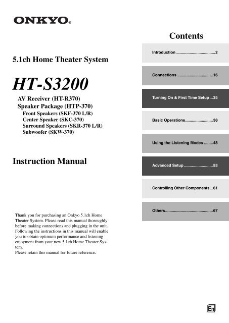
5.1ch Home Theater System<br />
<strong>HT</strong>-S3200<br />
<strong>AV</strong> <strong>Receiver</strong> (<strong>HT</strong>-<strong>R370</strong>)<br />
Speaker Package (<strong>HT</strong>P-370)<br />
Front Speakers (SKF-370 L/R)<br />
Center Speaker (SKC-370)<br />
Surround Speakers (SKR-370 L/R)<br />
Subwoofer (SKW-370)<br />
Instruction Manual<br />
Thank you for purchasing an <strong>Onkyo</strong> 5.1ch Home<br />
Theater System. Please read this manual thoroughly<br />
before making connections and plugging in the unit.<br />
Following the instructions in this manual will enable<br />
you to obtain optimum performance and listening<br />
enjoyment from your new 5.1ch Home Theater System.<br />
Please retain this manual for future reference.<br />
Contents<br />
Introduction ...................................2<br />
Connections ................................16<br />
Turning On & First Time Setup...35<br />
Basic Operations.........................38<br />
Using the Listening Modes ........48<br />
Advanced Setup ..........................53<br />
Controlling Other Components...61<br />
Others...........................................67<br />
En
2<br />
WARNING:<br />
TO REDUCE THE RISK OF FIRE OR ELECTRIC<br />
SHOCK, DO NOT EXPOSE THIS APPARATUS TO<br />
RAIN OR MOISTURE.<br />
CAUTION:<br />
TO REDUCE THE RISK OF ELECTRIC SHOCK,<br />
DO NOT REMOVE COVER (OR BACK). NO<br />
USER-SERVICEABLE PARTS INSIDE. REFER<br />
SERVICING TO QUALIFIED SERVICE<br />
PERSONNEL.<br />
Important Safety Instructions<br />
1. Read these instructions.<br />
2. Keep these instructions.<br />
3. Heed all warnings.<br />
4. Follow all instructions.<br />
5. Do not use this apparatus near water.<br />
6. Clean only with dry cloth.<br />
7. Do not block any ventilation openings. Install in<br />
accordance with the manufacturer’s instructions.<br />
8. Do not install near any heat sources such as radiators,<br />
heat registers, stoves, or other apparatus<br />
(including amplifiers) that produce heat.<br />
9. Do not defeat the safety purpose of the polarized or<br />
grounding-type plug. A polarized plug has two<br />
blades with one wider than the other. A grounding<br />
type plug has two blades and a third grounding<br />
prong. The wide blade or the third prong are provided<br />
for your safety. If the provided plug does not<br />
fit into your outlet, consult an electrician for<br />
replacement of the obsolete outlet.<br />
10. Protect the power cord from being walked on or<br />
pinched particularly at plugs, convenience receptacles,<br />
and the point where they exit from the apparatus.<br />
11. Only use attachments/accessories specified by the<br />
manufacturer.<br />
12. Use only with the cart, stand, PORTABLE CART WARNING<br />
tripod, bracket, or table specified<br />
by the manufacturer, or<br />
sold with the apparatus.<br />
When a cart is used, use caution<br />
when moving the cart/<br />
apparatus combination to S3125A<br />
avoid injury from tip-over.<br />
13. Unplug this apparatus during lightning storms or<br />
when unused for long periods of time.<br />
14. Refer all servicing to qualified service personnel.<br />
Servicing is required when the apparatus has been<br />
damaged in any way, such as power-supply cord or<br />
plug is damaged, liquid has been spilled or objects<br />
have fallen into the apparatus, the apparatus has<br />
been exposed to rain or moisture, does not operate<br />
normally, or has been dropped.<br />
WARNING<br />
RISK OF ELECTRIC SHOCK<br />
DO NOT OPEN<br />
<strong>AV</strong>IS<br />
RISQUE DE CHOC ELECTRIQUE<br />
NE PAS OUVRIR<br />
The lightning flash with arrowhead symbol, within an<br />
equilateral triangle, is intended to alert the user to the<br />
presence of uninsulated “dangerous voltage” within<br />
the product’s enclosure that may be of sufficient<br />
magnitude to constitute a risk of electric shock to<br />
persons.<br />
The exclamation point within an equilateral triangle is<br />
intended to alert the user to the presence of important<br />
operating and maintenance (servicing) instructions in<br />
the literature accompanying the appliance.<br />
15. Damage Requiring Service<br />
Unplug the apparatus from the wall outlet and refer<br />
servicing to qualified service personnel under the<br />
following conditions:<br />
A. When the power-supply cord or plug is damaged,<br />
B. If liquid has been spilled, or objects have fallen<br />
into the apparatus,<br />
C. If the apparatus has been exposed to rain or<br />
water,<br />
D. If the apparatus does not operate normally by<br />
following the operating instructions. Adjust<br />
only those controls that are covered by the operating<br />
instructions as an improper adjustment of<br />
other controls may result in damage and will<br />
often require extensive work by a qualified technician<br />
to restore the apparatus to its normal<br />
operation,<br />
E. If the apparatus has been dropped or damaged in<br />
any way, and<br />
F. When the apparatus exhibits a distinct change in<br />
performance this indicates a need for service.<br />
16. Object and Liquid Entry<br />
Never push objects of any kind into the apparatus<br />
through openings as they may touch dangerous<br />
voltage points or short-out parts that could result in<br />
a fire or electric shock.<br />
The apparatus shall not be exposed to dripping or<br />
splashing and no objects filled with liquids, such as<br />
vases shall be placed on the apparatus.<br />
Don’t put candles or other burning objects on top of<br />
this unit.<br />
17. Batteries<br />
Always consider the environmental issues and<br />
follow local regulations when disposing of batteries.<br />
18. If you install the apparatus in a built-in installation,<br />
such as a bookcase or rack, ensure that there is adequate<br />
ventilation.<br />
Leave 20 cm of free space at the top and sides and<br />
10 cm at the rear. The rear edge of the shelf or board<br />
above the apparatus shall be set 10 cm away from<br />
the rear panel or wall, creating a flue-like gap for<br />
warm air to escape.
Precautions<br />
1. Recording Copyright—Unless it’s for personal use<br />
only, recording copyrighted material is illegal<br />
without the permission of the copyright holder.<br />
2. AC Fuse—The AC fuse inside the unit is not userserviceable.<br />
If you cannot turn on the unit, contact<br />
your <strong>Onkyo</strong> dealer.<br />
3. Care—Occasionally you should dust the unit all<br />
over with a soft cloth. For stubborn stains, use a soft<br />
cloth dampened with a weak solution of mild<br />
detergent and water. Dry the unit immediately<br />
afterwards with a clean cloth. Don’t use abrasive<br />
cloths, thinners, alcohol, or other chemical solvents,<br />
because they may damage the finish or remove the<br />
panel lettering.<br />
4. Power<br />
WARNING<br />
BEFORE PLUGGING IN THE UNIT FOR THE<br />
FIRST TIME, READ THE FOLLOWING<br />
SECTION CAREFULLY.<br />
AC outlet voltages vary from country to country.<br />
Make sure that the voltage in your area meets the<br />
voltage requirements printed on the unit’s rear panel<br />
(e.g., AC 230 V, 50 Hz or AC 120 V, 60 Hz).<br />
The power cord plug is used to disconnect this unit<br />
from the AC power source. Make sure that the plug<br />
is readily operable (easily accessible) at all times.<br />
Pressing the [ON/STANDBY] button to select<br />
Standby mode does not fully shutdown the unit. If<br />
you do not intend to use the unit for an extended<br />
period, remove the power cord from the AC outlet.<br />
5. Preventing Hearing Loss<br />
Caution<br />
Excessive sound pressure from earphones and<br />
headphones can cause hearing loss.<br />
6. Batteries and Heat Exposure<br />
Warning<br />
Batteries (battery pack or batteries installed) shall<br />
not be exposed to excessive heat as sunshine, fire or<br />
the like.<br />
7. Never Touch this Unit with Wet Hands—Never<br />
handle this unit or its power cord while your hands<br />
are wet or damp. If water or any other liquid gets<br />
inside this unit, have it checked by your <strong>Onkyo</strong><br />
dealer.<br />
8. Handling Notes<br />
If you need to transport this unit, use the original<br />
packaging to pack it how it was when you<br />
originally bought it.<br />
Do not leave rubber or plastic items on this unit<br />
for a long time, because they may leave marks on<br />
the case.<br />
This unit’s top and rear panels may get warm<br />
after prolonged use. This is normal.<br />
If you do not use this unit for a long time, it may<br />
not work properly the next time you turn it on, so<br />
be sure to use it occasionally.<br />
For British models<br />
Replacement and mounting of an AC plug on the power<br />
supply cord of this unit should be performed only by<br />
qualified service personnel.<br />
IMPORTANT<br />
The wires in the mains lead are coloured in accordance<br />
with the following code:<br />
Blue: Neutral<br />
Brown: Live<br />
As the colours of the wires in the mains lead of this<br />
apparatus may not correspond with the coloured<br />
markings identifying the terminals in your plug, proceed<br />
as follows:<br />
The wire which is coloured blue must be connected to<br />
the terminal which is marked with the letter N or<br />
coloured black.<br />
The wire which is coloured brown must be connected to<br />
the terminal which is marked with the letter L or<br />
coloured red.<br />
IMPORTANT<br />
The plug is fitted with an appropriate fuse. If the fuse<br />
needs to be replaced, the replacement fuse must<br />
approved by ASTA or BSI to BS1362 and have the same<br />
ampere rating as that indicated on the plug. Check for the<br />
ASTA mark or the BSI mark on the body of the fuse.<br />
If the power cord’s plug is not suitable for your socket<br />
outlets, cut it off and fit a suitable plug. Fit a suitable fuse<br />
in the plug.<br />
For European Models<br />
Declaration of Conformity<br />
We, ONKYO EUROPE<br />
ELECTRONICS GmbH<br />
LIEGNITZERSTRASSE 6,<br />
82194 GROEBENZELL,<br />
GERMANY<br />
declare in own responsibility, that the ONKYO product<br />
described in this instruction manual is in compliance with the<br />
corresponding technical standards such as EN60065,<br />
EN55013, EN55020 and EN61000-3-2, -3-3.<br />
GROEBENZELL, GERMANY<br />
K. MIYAGI<br />
ONKYO EUROPE ELECTRONICS GmbH<br />
3
4<br />
Speaker Precautions<br />
Placement<br />
The subwoofer cabinet is made out of wood and is<br />
therefore sensitive to extreme temperatures and<br />
humidity, do not put it in locations subject to direct<br />
sunlight or in humid places, such as near an air conditioner,<br />
humidifier, bathroom, or kitchen.<br />
Do not put water or other liquids close to the speakers.<br />
If liquid is spilled over the speakers, the drive units<br />
may be damaged.<br />
Speakers should only be placed on sturdy, flat surfaces<br />
that are free from vibration. Putting them on uneven or<br />
unstable surfaces, where they may fall and cause damage,<br />
will affect the sound quality.<br />
Subwoofer is designed to be used in the upright vertical<br />
position only. Do not use it in the horizontal or<br />
tilted position.<br />
If the unit is used near a turntable, CD player or DVD/<br />
BD player, howling or slipping of sound may occur.<br />
To prevent this, move the unit away from the turntable,<br />
CD player or DVD/BD player, otherwise lower the<br />
unit’s output level.<br />
Using Close to a TV or Computer<br />
TVs and computer monitors are magnetically sensitive<br />
devices and as such are likely to suffer discoloration or<br />
picture distortion when conventional speakers are placed<br />
nearby. To prevent this, the SKF-370 and SKC-370<br />
feature internal magnetic shielding. In some situations,<br />
however, discoloration may still be an issue, in which<br />
case you should turn off your TV or monitor, wait 15 to<br />
30 minutes, and then turn it back on again. This normally<br />
activates the degaussing function, which neutralizes the<br />
magnetic field, thereby removing any discoloration<br />
effects. If discoloration problems persist, try moving the<br />
speakers away from your TV or monitor. Note that<br />
discoloration can also be caused by a magnet or<br />
demagnetizing tool that’s too close to your TV or<br />
monitor.<br />
Do not place SKR-370 close to TV or a computer<br />
monitor because they have no magnetic shield.<br />
Input Signal Warning<br />
The speakers can handle the specified input power when<br />
used for normal music reproduction. If any of the<br />
following signals are fed to them, even if the input power<br />
is within the specified rating, excessive current may flow<br />
in the speaker coils, causing burning or wire breakage:<br />
1. Interstation noise from an untuned FM radio.<br />
2. Sound from fast-forwarding a cassette tape.<br />
3. High-pitched sounds generated by an oscillator,<br />
electronic musical instrument, and so on.<br />
4. Amplifier oscillation.<br />
5. Special test tones from audio test CDs and so on.<br />
6. Thumps and clicks caused by connecting or disconnecting<br />
audio cables. (Always turn off your amplifier<br />
before connecting or disconnecting cables.)<br />
7. Microphone feedback.
Contents<br />
Introduction<br />
Important Safety Instructions .................................... 2<br />
Precautions ............................................................... 3<br />
Speaker Precautions................................................. 4<br />
Package Contents..................................................... 5<br />
Features.................................................................... 7<br />
Front & Rear Panels.................................................. 8<br />
Speaker Package.................................................... 12<br />
Remote Controller................................................... 13<br />
Enjoying Home Theater .......................................... 15<br />
Connections<br />
Connecting the <strong>AV</strong> receiver .................................... 16<br />
Turning on & First Time Setup<br />
Turning On the <strong>AV</strong> <strong>Receiver</strong> ................................... 35<br />
First Time Setup...................................................... 36<br />
Basic Operations<br />
Basic Operations..................................................... 38<br />
Listening to the Radio ............................................. 42<br />
Recording................................................................ 47<br />
Using the Listening Modes<br />
Using the Listening Modes...................................... 48<br />
Advanced Setup<br />
Advanced Setup...................................................... 53<br />
Controlling Other Components<br />
Controlling Other Components................................ 61<br />
Others<br />
Troubleshooting ...................................................... 67<br />
Specifications.......................................................... 70<br />
* To reset the <strong>AV</strong> receiver to its factory defaults, turn it on and,<br />
while holding down the [VCR/DVR] button, press the<br />
[ON/STANDBY] button (see page 67).<br />
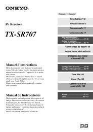
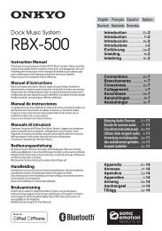
Package Contents<br />
Make sure you have the following items:<br />
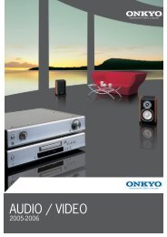
<strong>AV</strong> <strong>Receiver</strong> <strong>HT</strong>-<strong>R370</strong><br />
<strong>HT</strong>-<strong>R370</strong><br />
Remote controller and two batteries (AA/R6)<br />
Indoor FM antenna<br />
AM loop antenna<br />
In catalogs and on packaging, the letter at the end of the product<br />
name indicates the color. Specifications and operations are the<br />
same regardless of color.<br />
5
6<br />
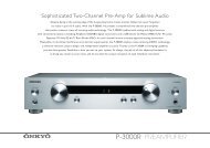
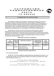
Package Contents—Continued<br />
Speaker Package <strong>HT</strong>P-370<br />
Front speakers<br />
(SKF-370 L/R)<br />
Center speaker<br />
(SKC-370)<br />
Surround speakers<br />
(SKR-370 L/R)<br />
Subwoofer (SKW-370)<br />
Speaker Package Accessories<br />
(White)<br />
Speaker cables for front speakers 3.5 m<br />
Speaker cable for center speaker 3 m<br />
(Blue)<br />
(Green)<br />
Speaker cables for surround speakers 8 m<br />
(Purple)<br />
Speaker cable for subwoofer 4 m<br />
16 thin rubber stoppers, 12 thick rubber stoppers<br />
4 floor pads for the subwoofer<br />
(Red)<br />
(Glay)
Features<br />
<strong>AV</strong> <strong>Receiver</strong> <strong>HT</strong>-<strong>R370</strong><br />
*1<br />
*2<br />
100 Watts/Channel @ 6 ohms (IEC)<br />
H.C.P.S. (High Current Power Supply) Massive High<br />
Power Transformer<br />
Dolby Digital and Pro Logic II *1<br />
DTS and DTS Neo:6 5.1 *2<br />
Music Optimizer *3 for Digital Audio Files<br />
CinemaFILTER<br />
3 HDMI *4 Inputs and 1 Output (Pass-Thru)<br />
Component Video Switching (2 Inputs/1 Output)<br />
Front “Portable” Input for iPod ®*7 and MP3 Players<br />
3 Digital Inputs (2 Optical/1 Coaxial)<br />
Speaker A/ B Drive<br />
Color-Coded Speaker Terminals<br />
Audyssey EQ *5 to Correct Room Acoustic Problems<br />
Audyssey Dynamic EQ *5 for Loudness Correction<br />
Audyssey Dynamic Volume *5 to Maintain Optimal<br />
Listening Level and Dynamic Range<br />
EX.BASS for natural deeper bass<br />
Crossover Adjustment<br />
(40/50/60/80/100/120/150/200Hz)<br />
A/V Sync Control (up to 100 ms in 20 ms Steps)<br />
Theater Dimensional Virtual Surround Function *6<br />
RI-Compatible Remote Control<br />
Manufactured under license from Dolby Laboratories. “Dolby”,<br />
“Pro Logic” and the double-D symbol are trademarks of Dolby<br />
Laboratories.<br />
Manufactured under license under U.S. Patent #’s: 5,451,942;<br />
5,956,674; 5,974,380; 5,978,762; 6,226,616; 6,487,535;<br />
7,003,467 & other U.S. and worldwide patents issued &<br />
pending.<br />
DTS, DTS Digital Surround, and Neo: 6 are registered<br />
trademarks and the DTS logos, Symbol and DTS 96/24 are<br />
trademarks of DTS, Inc.<br />
© 1996-2008 DTS, Inc. All Rights Reserved.<br />
*3 Music Optimizer is a trademark of <strong>Onkyo</strong> Corporation.<br />
*4<br />
HDMI, the HDMI logo and High Definition Multimedia<br />
Interface are trademarks or registered trademarks of HDMI<br />
Licensing, LLC.<br />
*5<br />
Manufactured under license from Audyssey Laboratories. U.S.<br />
and foreign patents pending.<br />
Audyssey EQ, Audyssey Dynamic Volume, and<br />
Audyssey Dynamic EQ are trademarks of Audyssey<br />
Laboratories.<br />
*6<br />
Theater-Dimensional is a trademark of <strong>Onkyo</strong> Corporation.<br />
*7 Apple and iPod are trademarks of Apple Inc., registered in the<br />
U.S. and other countries.<br />
Speaker Package <strong>HT</strong>P-370<br />
SKF-370 L/R Full-Range Front Speakers<br />
SKC-370 Full-Range Center Speaker<br />
8 cm full-range speaker<br />
Gloss Finished<br />
Max. input power:120 W<br />
Magnetically shielded<br />
Color-coded speaker terminals and speaker cable<br />
6-ohm impedance<br />
SKR-370 L/R Full-Range Surround Speakers<br />
8 cm full-range speaker<br />
Gloss Finished<br />
Max. input power:120 W<br />
Color-coded speaker terminals and speaker cable<br />
6-ohm impedance<br />
SKW-370 Bass Reflex Subwoofer<br />
20 cm cone woofer<br />
Down-Firing<br />
Color-coded speaker terminals and speaker cable<br />
7
14<br />
Remote Controller—Continued<br />
Installing the Batteries<br />
1<br />
2<br />
3<br />
To open the battery compartment, press<br />
the small lever and remove the cover.<br />
Insert the two supplied batteries (AA/R6)<br />
in accordance with the polarity diagram<br />
inside the battery compartment.<br />
Replace the cover and push it shut.<br />
Notes:<br />
If the remote controller doesn’t work reliably, try<br />
replacing the batteries.<br />
Don’t mix new and old batteries or different types of<br />
batteries.<br />
If you intend not to use the remote controller for a long<br />
time, remove the batteries to prevent damage from<br />
leakage or corrosion.<br />
Expired batteries should be removed as soon as<br />
possible to prevent damage from leakage or corrosion.<br />
Aiming the Remote Controller<br />
When using the remote controller, point it toward the <strong>AV</strong><br />
receiver’s remote control sensor, as shown below.<br />
30°<br />
30°<br />
Remote control sensor<br />
STANDBY indicator <strong>AV</strong> receiver<br />
Approx. 5 m<br />
Notes:<br />
The remote controller may not work reliably if the <strong>AV</strong><br />
receiver is subjected to bright light, such as direct<br />
sunlight or inverter-type fluorescent lights. Keep this<br />
in mind when installing.<br />
If another remote controller of the same type is used in<br />
the same room, or the <strong>AV</strong> receiver is installed close to<br />
equipment that uses infrared rays, the remote<br />
controller may not work reliably.<br />
Don’t put anything on top of the remote controller,<br />
such as a book or magazine, because a button may be<br />
pressed continuously, thereby draining the batteries.<br />
The remote controller may not work reliably if the <strong>AV</strong><br />
receiver is installed in a rack behind colored glass<br />
doors. Keep this in mind when installing.<br />
The remote controller will not work if there’s an<br />
obstacle between it and the <strong>AV</strong> receiver’s remote<br />
control sensor.
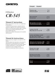
Enjoying Home Theater<br />
Speaker Sets A and B<br />
You can use two sets of speakers with the <strong>AV</strong> receiver: speaker set A and speaker set B.<br />
Speaker set A should be used in your main listening room for up to 5.1-channel playback.<br />
* While speaker set B is on, speaker set A is reduced to 2.1-channel playback.<br />
Speaker set B can be used in another room and offers 2-channel stereo playback.<br />
<strong>AV</strong> receiver<br />
or<br />
Remote<br />
controller<br />
Speaker set A Speaker set B Indicator Output<br />
On<br />
Off<br />
Center speaker (SKC-370)<br />
This speaker enhances the front left and right speakers,<br />
making sound movements distinct and providing a full sound<br />
image. For movies it’s used mainly for dialog.<br />
Position it close to your TV facing forward at about ear level,<br />
or at the same height as the front left and right speakers.<br />
* While speaker set B is on, this speaker outputs no sound.<br />
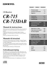
Subwoofer (SKW-370)<br />
The subwoofer handles the bass sounds of the<br />
LFE (Low-Frequency Effects) channel. In general,<br />
a good bass sound can be obtained by installing<br />
the subwoofer in a front corner, or at one-third<br />
the way along the wall, as shown.<br />
Tip:To find the best position for your subwoofer,<br />
while playing a movie or some music with good<br />
bass, experiment by placing your subwoofer at<br />
various positions within the room and choose the<br />
one that provides the most satisfying results.<br />
1/3 of wall<br />
position<br />
Corner<br />
position<br />
Speaker Set B: Sub Room<br />
On<br />
A B<br />
Set A: 2.1 channels<br />
Set B: 2 channels<br />
Off A Set A: 5.1 channels<br />
On B Set B: 2 channels<br />
Off No sound<br />
Speaker Set A: Main Room<br />
Front left and right speakers<br />
(SKF-370 L/R)<br />
These output the overall sound.<br />
Their role in a home theater is to<br />
provide a solid anchor for the sound<br />
image. They should be positioned<br />
facing the listener at about ear<br />
level, and equally spaced from the<br />
TV. Angle them inward.<br />
<strong>HT</strong>P-370 speaker<br />
package is shown<br />
Surround left and right speakers (SKR-370 L/R)<br />
These speakers are used for precise sound<br />
positioning and to add realistic ambience. Position<br />
them at the sides of the listener, or slightly behind,<br />
about 60–100 cm above ear level. Ideally they<br />
should be equally spaced from the listener.<br />
* While speaker set B is on, these speakers output no<br />
sound.<br />
15
16<br />
Connecting the <strong>AV</strong> receiver<br />
Connecting Your Speakers<br />
Speaker Connection Precautions<br />
Read the following before connecting your speakers:<br />
You can connect speakers with an impedance of<br />
6 ohms or higher. If you use speakers with a lower<br />
impedance, and use the amplifier at high volume<br />
levels for a long period of time, the built-in protection<br />
circuit may be activated.<br />
Disconnect the power cord from the wall outlet before<br />
making any connections.<br />
Read the instructions supplied with your speakers.<br />
Pay close attention to speaker wiring polarity. Connect<br />
positive (+) terminals to only positive (+) terminals,<br />
and negative (–) terminals to only negative (–)<br />
terminals. If you get them the wrong way around, the<br />
sound will be out of phase and will sound unnatural.<br />
Unnecessarily long or very thin speaker cables may<br />
affect the sound quality and should be avoided.<br />
Be careful not to short the positive and negative wires.<br />
Doing so may damage the <strong>AV</strong> receiver.<br />
FRONT SPEAKERS A OTHERS<br />
Don’t connect more than one cable to each speaker<br />
terminal. Doing so may damage the <strong>AV</strong> receiver.<br />
Don’t connect a speaker to several terminals.<br />
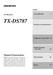
Connecting the Speaker Cables<br />
The <strong>AV</strong> receiver’s positive (+) speaker terminals are<br />
color-coded for ease of identification. (The negative (–)<br />
speaker terminals are all black.)<br />
Speaker Color<br />
Front left White<br />
Front right Red<br />
Center Green<br />
Surround left Blue<br />
Surround right Gray<br />
Subwoofer Purple<br />
FRONT SPEAKERS A<br />
1 Strip 12–15 mm of<br />
insulation from the<br />
ends of the speaker<br />
cables. (Supplied<br />
speaker cables are<br />
already stripped.)<br />
2 Unscrew the terminal.<br />
3 Fully insert the bare wire.<br />
4 Screw the terminal tight.<br />
12–15 mm
Connecting the <strong>AV</strong> receiver—Continued<br />
OTHERS<br />
1 Strip 10–12 mm of<br />
insulation from the<br />
ends of the speaker<br />
cables. (Supplied<br />
speaker cables are<br />
already stripped.)<br />
2 While pressing the lever,<br />
insert the wire into the<br />
hole, and then release the<br />
lever.<br />
Make sure that the<br />
terminals are gripping the bare wires, not<br />
the insulation.<br />
The following illustration shows which speaker should be connected to each pair of terminals.<br />
Red<br />
Front right<br />
speaker<br />
White<br />
Front left<br />
speaker<br />
10–12 mm<br />
Purple<br />
Subwoofer<br />
Gray<br />
Surround<br />
right speaker<br />
Blue<br />
Surround<br />
left speaker<br />
Green<br />
Center<br />
speaker<br />
17
18<br />
Connecting the <strong>AV</strong> receiver—Continued<br />
Wall Mounting<br />
The speakers can easily be wall mounted by using the<br />
keyhole slots. To prevent the speaker from vibrating<br />
against the wall, attach two of the supplied thick rubber<br />
stoppers to the rear of each speaker.<br />
To mount the front or surround speakers vertically, use<br />
the keyhole slot shown to hang each speaker on a screw<br />
that’s securely screwed into the wall.<br />
Front speakers (SKF-370)<br />
Thick<br />
rubber<br />
stoppers<br />
Surround speakers (SKR-370)<br />
Thick<br />
rubber<br />
stoppers<br />
To mount the center speaker horizontally, use the two<br />
keyhole slots shown to hang each speaker on two screws<br />
that are securely screwed into the wall.<br />
Center speaker (SKC-370)<br />
Thick<br />
rubber<br />
stoppers<br />
Keyhole slot for wall<br />
mounting<br />
Keyhole slot for wall<br />
mounting<br />
Keyhole slot for wall mounting<br />
217 mm<br />
Caution:<br />
A mounting screw’s ability to support a speaker depends<br />
on how well it’s anchored to the wall. If you have hollow<br />
walls, screw each mounting screw into a stud. If there are<br />
no studs, or the walls are solid, use suitable wall anchors.<br />
Use screws with a head diameter of 9 mm or less and a<br />
shank diameter of 4 mm or less. With hollow walls, use<br />
a cable/pipe detector to check for any power cables or<br />
water pipes before making any holes.<br />
Leave a gap of between 5 mm<br />
and 10 mm between the wall<br />
and the base of the screw head,<br />
as shown. (We recommend<br />
that you consult a home<br />
installation professional.)<br />
Using the Rubber Stoppers for a<br />
More Stable Platform<br />
We recommend using the provided rubber stoppers to<br />
achieve the best possible sound from your speakers. The<br />
rubber stoppers prevent the speakers from moving,<br />
providing a more stable platform. Use thick stoppers for<br />
the center speaker, and thin stoppers for the other<br />
speakers.<br />
Thin rubber stoppers<br />
Bottom of the<br />
SKC-370<br />
Bottom of the<br />
SKF-370<br />
5 mm – 10 mm<br />
12 mm<br />
Wall<br />
Bottom of the<br />
SKR-370<br />
Thick rubber stoppers<br />
55 mm<br />
Using the Floor Pads for Subwoofer<br />
If the subwoofer is placed on a hard floor (wood, vinyl,<br />
tile, etc.) and playback is very loud, the subwoofer’s feet<br />
may damage the flooring. To prevent this, place the<br />
supplied pads underneath the subwoofer’s feet. The pads<br />
also provide a stable base for the subwoofer.<br />
Pad
Connecting the <strong>AV</strong> receiver—Continued<br />
Connecting Antenna<br />
This section explains how to connect the supplied indoor<br />
FM antenna and AM loop antenna, and how to connect<br />
commercially available outdoor FM and AM antennas.<br />
The <strong>AV</strong> receiver won’t pick up any radio signals without<br />
any antenna connected, so you must connect the antenna<br />
to use the tuner.<br />
Connecting the Indoor FM Antenna<br />
The supplied indoor FM antenna is for indoor use only.<br />
1<br />
2<br />
AM ANTENNA push terminals<br />
FM ANTENNA jack<br />
Attach the FM antenna, as shown.<br />
Insert the plug fully<br />
into the jack.<br />
Once your <strong>AV</strong> receiver is ready for use, you’ll<br />
need to tune into an FM radio station and adjust<br />
the position of the FM antenna to achieve the best<br />
possible reception.<br />
Use thumbtacks or something similar to<br />
fix the FM antenna into position.<br />
Thumbtacks, etc.<br />
Caution:<br />
Be careful that you don’t injure yourself when<br />
using thumbtacks.<br />
If you cannot achieve good reception with the supplied<br />
indoor FM antenna, try a commercially available<br />
outdoor FM antenna instead (see page 20).<br />
Connecting the AM Loop Antenna<br />
The supplied indoor AM loop antenna is for indoor use<br />
only.<br />
1<br />
2<br />
Assemble the AM loop antenna, inserting<br />
the tabs into the base, as shown.<br />
Connect both wires of the AM loop<br />
antenna to the AM push terminals, as<br />
shown.<br />
(The antenna’s wires are not polarity sensitive, so<br />
they can be connected either way around.)<br />
Make sure that the wires are attached securely and<br />
that the push terminals are gripping the bare<br />
wires, not the insulation.<br />
Push Insert wire Release<br />
Once your <strong>AV</strong> receiver is ready for use, you’ll<br />
need to tune into an AM radio station and adjust<br />
the position of the AM antenna to achieve the best<br />
possible reception.<br />
Keep the antenna as far away as possible from<br />
your <strong>AV</strong> receiver, TV, speaker cables, and power<br />
cords.<br />
If you cannot achieve good reception with the supplied<br />
indoor AM loop antenna, try using it with a<br />
commercially available outdoor AM antenna (see<br />
page 20).<br />
19
20<br />
Connecting the <strong>AV</strong> receiver—Continued<br />
Connecting an Outdoor FM Antenna<br />
If you cannot achieve good reception with the supplied<br />
indoor FM antenna, try a commercially available<br />
outdoor FM antenna instead.<br />
Notes:<br />
Outdoor FM antennas work best outside, but usable<br />
results can sometimes be obtained when installed in an<br />
attic or loft.<br />
For best results, install the outdoor FM antenna well<br />
away from tall buildings, preferably with a clear line<br />
of sight to your local FM transmitter.<br />
Outdoor antenna should be located away from<br />
possible noise sources, such as neon signs, busy roads,<br />
etc.<br />
For safety reasons, outdoor antenna should be situated<br />
well away from power lines and other high-voltage<br />
equipment.<br />
Outdoor antenna must be grounded in accordance<br />
with local regulations to prevent electrical shock<br />
hazards.<br />
■ Using a TV/FM Antenna Splitter<br />
It’s best not to use the same antenna for both FM and TV<br />
reception, as this can cause interference problems. If<br />
circumstances demand it, use a TV/FM antenna splitter,<br />
as shown.<br />
TV/FM antenna splitter<br />
To <strong>AV</strong> receiver To TV (or VCR)<br />
Connecting an Outdoor AM Antenna<br />
If good reception cannot be achieved using the supplied<br />
AM loop antenna, an outdoor AM antenna can be used<br />
in addition to the loop antenna, as shown.<br />
AM loop antenna<br />
Outdoor antenna<br />
Insulated antenna cable<br />
Outdoor AM antennas work best when installed<br />
horizontally outside, but good results can sometimes be<br />
obtained indoors by mounting horizontally above a<br />
window. Note that the AM loop antenna should be left<br />
connected.<br />
Outdoor antenna must be grounded in accordance with<br />
local regulations to prevent electrical shock hazards.
Connecting the <strong>AV</strong> receiver—Continued<br />
About <strong>AV</strong> Connections<br />
Before making any <strong>AV</strong> connections, read the manuals<br />
supplied with your other <strong>AV</strong> components.<br />
Don’t connect the power cord until you’ve completed<br />
and double-checked all <strong>AV</strong> connections.<br />
Optical Digital Jacks<br />
The <strong>AV</strong> receiver’s optical digital jacks have shutter-type<br />
covers that open when an optical plug is inserted and<br />
close when it’s removed. Push plugs in all the way.<br />
Caution:<br />
To prevent shutter damage, hold the optical plug straight<br />
when inserting and removing.<br />
<strong>AV</strong> Cables and Jacks<br />
Video/Audio<br />
HDMI<br />
Video<br />
Component<br />
video cable<br />
Composite<br />
video cable<br />
Audio<br />
Optical<br />
digital audio<br />
cable<br />
Coaxial<br />
digital audio<br />
cable<br />
Analog audio<br />
cable (RCA)<br />
Stereo mini<br />
plug cable<br />
Y<br />
Note: The <strong>AV</strong> receiver does not support SCART connections.<br />
<strong>AV</strong> Connection Color Coding<br />
RCA-type <strong>AV</strong> connections are usually color coded: red,<br />
white, and yellow. Use red plugs to connect rightchannel<br />
audio inputs and outputs (typically labeled “R”).<br />
Use white plugs to connect left-channel audio inputs and<br />
outputs (typically labeled “L”). And use yellow plugs to<br />
connect composite video inputs and outputs.<br />
Left (white)<br />
Analog audio<br />
Right (red) Right (red)<br />
(Yellow)<br />
Composite video<br />
Push plugs in all the way to make<br />
good connections (loose<br />
connections can cause noise or<br />
malfunctions).<br />
To prevent interference, keep<br />
audio and video cables away from<br />
power cords and speaker cables.<br />
Cable Jack Description<br />
PB/CB<br />
PR/CR<br />
Y<br />
PB/CB<br />
PR/CR<br />
HDMI<br />
Y<br />
CB/PB<br />
CR/PR<br />
OPTICAL<br />
COAXIAL<br />
L<br />
R<br />
V<br />
Left (white)<br />
(Yellow)<br />
Right!<br />
Wrong!<br />
HDMI connections can carry uncompressed standard-<br />
or high-definition digital video and audio and offer the<br />
best picture and sound quality.<br />
Component video separates the luminance (Y) and<br />
color difference signals (PR, PB), providing the best<br />
picture quality. (Some TV manufacturers label their<br />
component video jacks slightly differently.)<br />
Composite video is commonly used on TVs, VCRs,<br />
and other video equipment.<br />
This offers the best sound quality and allows you to<br />
enjoy Dolby Digital and DTS. The audio quality is the<br />
same as for coaxial.<br />
This offers the best sound quality and allows you to<br />
enjoy Dolby Digital and DTS. The audio quality is the<br />
same as for optical.<br />
This cable carries analog audio. It’s the most common<br />
connection format for analog audio and can be found<br />
on virtually all <strong>AV</strong> components.<br />
This cable carries analog audio.<br />
21
22<br />
Connecting the <strong>AV</strong> receiver—Continued<br />
Connecting Audio and Video Signals to the <strong>AV</strong> <strong>Receiver</strong><br />
By connecting both the audio and video outputs of your DVD player and other <strong>AV</strong> components to the <strong>AV</strong> receiver, you<br />
can switch the audio and video signals simultaneously simply by changing the input source on the <strong>AV</strong> receiver.<br />
: Signal Flow<br />
Video<br />
Audio<br />
DVD/BD player, etc.<br />
Which Connections Should I Use?<br />
The <strong>AV</strong> receiver supports several connection formats for compatibility with a wide range of <strong>AV</strong> equipment. The format<br />
you choose will depend on the formats supported by your other components. Use the following sections as a guide.<br />
For video components, you must make an audio connection and a video connection.<br />
Video Connection Formats<br />
Video equipment can be connected to the <strong>AV</strong><br />
receiver by using any one of the following<br />
video connection formats: composite video,<br />
component video, or HDMI, the latter offering<br />
the best picture quality.<br />
When choosing a connection format, bear in<br />
mind that the <strong>AV</strong> receiver doesn’t convert<br />
between formats, so only outputs of the same<br />
format as the input will output the signal.<br />
Audio Connection Formats<br />
Audio equipment can be connected to the <strong>AV</strong><br />
receiver by using any of the following audio<br />
connection formats: analog, optical, coaxial, or<br />
HDMI.<br />
When you connect audio equipment to an<br />
OPTICAL or COAXIAL input, you must<br />
assign that input to an input selector<br />
(see page 36).<br />
Audio signals received by the HDMI IN jacks<br />
are output only by the HDMI OUT (Pass-<br />
Thru). HDMI sources are not output by the<br />
speakers connected to the <strong>AV</strong> receiver.<br />
Video<br />
Audio<br />
Speakers (see page 17 for hookup details)<br />
Video Signal Flow Chart<br />
DVD player, etc.<br />
<strong>AV</strong> receiver<br />
TV, projector, etc.<br />
Composite<br />
Audio Signal Flow Chart<br />
DVD player, etc.<br />
<strong>AV</strong> receiver<br />
TV, projector, etc.<br />
Component<br />
IN<br />
MONITOR OUT<br />
TV, projector,<br />
etc.<br />
HDMI<br />
Composite Component HDMI<br />
HDMI<br />
HDMI<br />
Optical Coaxial Analog<br />
Analog
Connecting the <strong>AV</strong> receiver—Continued<br />
Connecting Components with HDMI<br />
About HDMI<br />
Designed to meet the increased demands of digital TV, HDMI (High Definition Multimedia Interface) is a new digital<br />
interface standard for connecting TVs, projectors, DVD/BD players, set-top boxes, and other video components. Until<br />
now, several separate video and audio cables have been required to connect <strong>AV</strong> components. With HDMI, a single cable<br />
can carry control signals, digital video, and up to eight channels of digital audio (2-channel PCM, multichannel digital<br />
audio, or multichannel PCM).<br />
The HDMI video stream (i.e., video signal) is compatible with DVI (Digital Visual Interface) *1 , so TVs and displays<br />
with a DVI input can be connected by using an HDMI-to-DVI adapter cable. (This may not work with some TVs and<br />
displays, resulting in no picture.)<br />
The <strong>AV</strong> receiver uses HDCP (High-bandwidth Digital Content Protection), so only HDCP-compatible components will<br />
display a picture.<br />
The <strong>AV</strong> receiver’s HDMI interface is based on the following standard:<br />
Pass-Thru<br />
About Copyright Protection<br />
The <strong>AV</strong> receiver supports HDCP (High-bandwidth Digital Content Protection) *2 , a copy-protection system for digital<br />
video signals. Other devices connected to the <strong>AV</strong> receiver via HDMI must also support HDCP.<br />
Use a commercially available HDMI cable (supplied with some components) to connect the <strong>AV</strong> receiver’s HDMI OUT<br />
to the HDMI input on your TV or projector.<br />
*1 DVI (Digital Visual Interface): The digital display interface standard set by the DDWG *3 in 1999.<br />
*2 HDCP (High-bandwidth Digital Content Protection): The video encryption technology developed by Intel for HDMI/DVI. It’s designed to<br />
protect video content and requires a HDCP-compatible device to display the encrypted video.<br />
*3 DDWG (Digital Display Working Group): Led by Intel, Compaq, Fujitsu, Hewlett Packard, IBM, NEC, and Silicon Image, this open<br />
industry group’s objective is to address the industry’s requirements for a digital connectivity specification for high-performance PCs and<br />
digital displays.<br />
23
24<br />
Connecting the <strong>AV</strong> receiver—Continued<br />
Making HDMI Connections<br />
If you have an HDMI-compatible player, you can connect it to the <strong>AV</strong> receiver with an HDMI cable.<br />
Step 1: Connect your HDMI-compatible TV to the <strong>AV</strong> receiver’s HDMI OUT jack.<br />
Step 2: Connect your HDMI-compatible player to the <strong>AV</strong> receiver’s HDMI IN 1, 2, or 3 jack.<br />
Step 3: Connect your HDMI-compatible player to an analog and/or digital audio input on the <strong>AV</strong><br />
receiver.<br />
■ Audio Signals<br />
Audio and video signals received via inputs other than the HDMI IN jacks are not output by the HDMI OUT.<br />
Audio and video signals received via the HDMI IN jacks are output only by the HDMI OUT.<br />
To watch an HDMI source that’s connected via the <strong>AV</strong> receiver’s HDMI jacks, the <strong>AV</strong> receiver must be turned<br />
on, otherwise no HDMI signal will be output.<br />
If you want to listen through the speakers connected to the <strong>AV</strong> receiver, in addition to an HDMI connection,<br />
you’ll also need to make a separate analog or digital audio connection.<br />
DVD/BD player<br />
Step 3<br />
Connect one<br />
or the other.<br />
HDMI<br />
OUT<br />
Step 2<br />
HDMI<br />
IN<br />
Step 1<br />
Tip!<br />
If you make the connection described in<br />
step 3, to fully enjoy the <strong>AV</strong> receiver’s<br />
listening modes, turn down the volume<br />
on your TV all the way so that its<br />
speakers output no sound.<br />
Sound off<br />
Notes:<br />
The HDMI video stream is compatible with DVI (Digital Visual Interface), so TVs and displays with a DVI input can<br />
be connected by using an HDMI-to-DVI adapter cable. (Note that DVI connections only carry video, so you’ll need<br />
to make a separate connection for audio.) However, reliable operation with such an adapter is not guaranteed. In<br />
addition, video signals from a PC are not supported.<br />
When listening to an HDMI component through the <strong>AV</strong> receiver, set the HDMI component so that its video can be<br />
seen on the TV screen (on the TV, select the input of the HDMI component connected to the <strong>AV</strong> receiver).<br />
The HDMI audio signal (sampling rate, bit length, etc.) may be restricted by the connected source component. If the<br />
picture is poor or there’s no sound from a component connected via HDMI, check its setup. Refer to the connected<br />
component’s instruction manual for details.<br />
TV
Connecting the <strong>AV</strong> receiver—Continued<br />
Connecting a TV or Projector<br />
Step 1: Video Connection<br />
Choose a video connection that matches your TV ( or ), and then make the connection.<br />
A B<br />
Step 2: Audio Connection<br />
Choose an audio connection that matches your TV ( , , or ), and then make the connection.<br />
a b c<br />
With connection a , you can listen to and record audio from your TV.<br />
To enjoy Dolby Digital and DTS, use connection b or c .<br />
Connection <strong>AV</strong> receiver Signal flow TV<br />
A<br />
COMPONENT VIDEO OUT ⇒ Component video input<br />
B<br />
MONITOR OUT V ⇒ Composite video input<br />
a<br />
b<br />
c<br />
TV/TAPE IN L/R ⇐ Analog audio L/R output<br />
DIGITAL IN COAXIAL (DVD/BD) ⇐ Digital coaxial output<br />
DIGITAL IN OPTICAL 1 (CBL/SAT) ⇐ Digital optical output<br />
c<br />
b<br />
OPTICAL<br />
OUT<br />
Connect one or the other.<br />
Connection c must be assigned<br />
(see page 36).<br />
Hint!<br />
COAXIAL<br />
OUT<br />
L R<br />
AUDIO<br />
OUT<br />
a C B<br />
Y PB PR<br />
COMPONENT VIDEO IN<br />
If your TV has no audio outputs, connect an audio output from your VCR or cable or satellite receiver<br />
to the <strong>AV</strong> receiver and use its tuner to listen to TV programs through the <strong>AV</strong> receiver (see pages 27 and<br />
29).<br />
VIDEO<br />
IN<br />
TV, projector,<br />
etc.<br />
A<br />
25
26<br />
Connecting the <strong>AV</strong> receiver—Continued<br />
Connecting a DVD/BD Player<br />
Step 1: Video Connection<br />
Choose a video connection that matches your DVD/BD player ( A or B ), and then make the connection.<br />
You must connect the <strong>AV</strong> receiver to your TV with the same type of connection.<br />
Step 2: Audio Connection<br />
Choose an audio connection that matches your DVD/BD player ( , , or ), and then make the connection.<br />
a b c<br />
With connection a , you can listen to and record audio from a DVD.<br />
To enjoy Dolby Digital and DTS, use connection b or c . (To record as well, use a and b , or a and c .)<br />
If your DVD/BD player has main left and right outputs and multichannel left and right outputs, be sure to use the main<br />
left and right outputs for connection a .<br />
Connection <strong>AV</strong> receiver Signal flow DVD/BD player<br />
A<br />
B<br />
a<br />
b<br />
c<br />
COMPONENT VIDEO IN 1 (DVD/BD) ⇐ Component video output<br />
DVD/BD IN V ⇐ Composite video output<br />
DVD/BD IN L/R ⇐ Analog audio L/R output<br />
DIGITAL IN COAXIAL (DVD/BD) ⇐ Digital coaxial output<br />
DIGITAL IN OPTICAL 1 (CBL/SAT) ⇐ Digital optical output<br />
b<br />
Connect one or the other.<br />
Connection c<br />
must be<br />
assigned (see page 36).<br />
c A<br />
OPTICAL<br />
OUT<br />
COAXIAL<br />
OUT<br />
VIDEO<br />
OUT<br />
CB a<br />
L R<br />
AUDIO<br />
OUT<br />
DVD/BD player<br />
Y PB PR<br />
COMPONENT VIDEO OUT
Connecting the <strong>AV</strong> receiver—Continued<br />
Connecting a VCR or DVR for Playback<br />
Hint!<br />
With this hookup, you can use the tuner in your VCR or DVR to listen to your favorite TV programs<br />
via the <strong>AV</strong> receiver, which is useful if your TV has no audio outputs.<br />
Step 1: Video Connection<br />
Choose a video connection that matches your VCR or DVR ( A or B ), and then make the connection. You must<br />
connect the <strong>AV</strong> receiver to your TV with the same type of connection.<br />
Step 2: Audio Connection<br />
Choose an audio connection that matches your VCR or DVR ( , , or ), and then make the connection.<br />
a b c<br />
To enjoy Dolby Digital and DTS, use connection b or c .<br />
Connection <strong>AV</strong> receiver Signal flow VCR or DVR<br />
A<br />
B<br />
a<br />
b<br />
c<br />
COMPONENT VIDEO IN 2 (CBL/SAT) ⇐ Component video output<br />
VCR/DVR IN V ⇐ Composite video output<br />
VCR/DVR IN L/R ⇐ Analog audio L/R output<br />
DIGITAL IN COAXIAL (DVD/BD) ⇐ Digital coaxial output<br />
DIGITAL IN OPTICAL 1 (CBL/SAT) ⇐ Digital optical output<br />
b<br />
Connect one or the other.<br />
Connection b<br />
must be<br />
assigned (see page 36).<br />
c A<br />
OPTICAL<br />
OUT<br />
COAXIAL<br />
OUT<br />
VIDEO<br />
OUT<br />
CB a<br />
L R<br />
AUDIO<br />
OUT<br />
VCR or DVR<br />
Y PB PR<br />
COMPONENT VIDEO OUT<br />
27
28<br />
Connecting the <strong>AV</strong> receiver—Continued<br />
Connecting a VCR or DVR for Recording<br />
Step 1: Video Connection<br />
Make the video connection .<br />
A<br />
Step 2: Audio Connection<br />
Make the audio connection .<br />
a<br />
Connection <strong>AV</strong> receiver Signal flow VCR or DVD recorder<br />
A<br />
VCR/DVR OUT V ⇒ Composite video input<br />
a<br />
VCR/DVR OUT L/R ⇒ Audio L/R input<br />
VIDEO<br />
IN<br />
CA a<br />
VCR or DVR<br />
L R<br />
AUDIO<br />
IN<br />
Notes:<br />
The <strong>AV</strong> receiver must be turned on for recording. Recording is not possible while it’s on Standby.<br />
If you want to record directly from your TV or another video source without going through the <strong>AV</strong> receiver, connect<br />
the audio and video outputs from your TV or other video component directly to the recording VCR/DVR’s audio and<br />
video inputs. See the manuals supplied with your TV or VCR/DVR for details.<br />
Video signals connected to composite video inputs can only be recorded via the VCR/DVR OUT V jack. So if your<br />
source TV or VCR is connected to a composite video input, the recording VCR/DVR must be connected to the<br />
VCR/DVR OUT V jack.
Connecting the <strong>AV</strong> receiver—Continued<br />
Connecting a Satellite, Cable, Terrestrial Set-top box, or Other Video Source<br />
Hint!<br />
With this hookup, you can use your satellite or cable receiver to listen to your favorite TV programs<br />
via the <strong>AV</strong> receiver, which is useful if your TV has no audio outputs.<br />
Step 1: Video Connection<br />
Choose a video connection that matches the video source ( A or B ), and then make the connection.<br />
You must connect the <strong>AV</strong> receiver to your TV with the same type of connection.<br />
Step 2: Audio Connection<br />
Choose an audio connection that matches the video source ( , , or ), and then make the connection.<br />
a b c<br />
With connection a , you can listen to and record audio from the video source.<br />
To enjoy Dolby Digital and DTS, use connection b or c . (To record as well, use a and b , or a and c .)<br />
Connection <strong>AV</strong> receiver Signal flow Video source<br />
A<br />
B<br />
a<br />
b<br />
c<br />
COMPONENT VIDEO IN 2 (CBL/SAT) ⇐ Component video output<br />
CBL/SAT IN V ⇐ Composite video output<br />
CBL/SAT IN L/R ⇐ Analog audio L/R output<br />
DIGITAL IN COAXIAL (DVD/BD) ⇐ Digital coaxial output<br />
DIGITAL IN OPTICAL 1 (CBL/SAT) ⇐ Digital optical output<br />
b<br />
Connect one or the other.<br />
Connection b<br />
must be<br />
assigned (see page 36).<br />
c A<br />
OPTICAL<br />
OUT<br />
COAXIAL<br />
OUT<br />
L R<br />
AUDIO<br />
OUT<br />
a CB<br />
VIDEO<br />
OUT<br />
Satellite, cable, set-top box, etc.<br />
Y PB PR<br />
COMPONENT VIDEO OUT<br />
29
30<br />
Connecting the <strong>AV</strong> receiver—Continued<br />
Connecting a Portable Audio Player<br />
Step 1: Make the audio connection .<br />
a<br />
AUX INPUT<br />
PORTABLE<br />
a<br />
AUDIO LINE OUT<br />
Portable<br />
Audio Player<br />
Connection <strong>AV</strong> receiver Signal flow Portable Audio Player<br />
a<br />
AUX INPUT PORTABLE ⇐ Analog audio Line output
Connecting the <strong>AV</strong> receiver—Continued<br />
Connecting a CD Player or Turntable<br />
■ CD Player or Turntable (MM) with Built-in Phono Preamp<br />
Step 1:<br />
Choose a connection that matches your CD player ( a , b , or c ). Use connection a for a turntable with a built-in<br />
phono preamp.<br />
Connect one<br />
or the other.<br />
Connection b<br />
must be<br />
assigned<br />
(see page 36).<br />
c<br />
b<br />
OPTICAL<br />
2<br />
(CD)<br />
COAXIAL<br />
(DVD/BD)<br />
OPTICAL COAXIAL<br />
OUT OUT<br />
L R<br />
AUDIO<br />
OUT<br />
With connection a , you can listen to and record audio from the CD player.<br />
To connect the CD player digitally, use connection b or c .<br />
Connection <strong>AV</strong> receiver Signal flow CD or turntable<br />
a<br />
CD IN L/R ⇐ Analog audio L/R output<br />
b DIGITAL IN COAXIAL (DVD/BD) ⇐ Digital coaxial output<br />
c DIGITAL IN OPTICAL 2 (CD) ⇐ Digital optical output<br />
■ Turntable (MM) with no Phono Preamp Built-in<br />
A phono preamp is necessary to connect a turntable that<br />
doesn’t have a phono preamp built-in.<br />
L<br />
IN<br />
R<br />
CD<br />
AUDIO<br />
OUTPUT<br />
AUDIO<br />
OUTPUT<br />
L<br />
R<br />
L<br />
R<br />
IN<br />
CD<br />
L<br />
R<br />
a<br />
Phono preamp<br />
AUDIO<br />
INPUT<br />
L<br />
R<br />
CD player<br />
L<br />
IN<br />
R<br />
CD<br />
a<br />
■ Turntable with an MC (Moving Coil) Cartridge<br />
An MC head amp and phono preamp are necessary to<br />
connect a turntable with an MC (Moving Coil) cartridge.<br />
L<br />
R<br />
IN<br />
CD<br />
AUDIO<br />
OUTPUT<br />
L<br />
R<br />
L<br />
R<br />
AUDIO<br />
OUTPUT<br />
Turntable (MM) with<br />
built-in phono preamp<br />
AUDIO<br />
OUTPUT<br />
L<br />
R<br />
AUDIO<br />
INPUT<br />
Phono<br />
preamp<br />
MC head amp or<br />
MC transformer<br />
L<br />
R<br />
AUDIO<br />
OUTPUT<br />
L<br />
R<br />
AUDIO<br />
INPUT<br />
L<br />
R<br />
31
32<br />
Connecting the <strong>AV</strong> receiver—Continued<br />
Connecting a Cassette, CDR, MiniDisc, or DAT Recorder<br />
Step 1:<br />
Choose a connection that matches your recorder ( , , or ), and then make the connection.<br />
a b c<br />
c<br />
b<br />
OPTICAL<br />
2<br />
(CD)<br />
COAXIAL<br />
(DVD/BD)<br />
Connect one or the other.<br />
These connections must be<br />
assigned (see page 36).<br />
With connection a , you can play and record.<br />
To connect the recorder digitally for playback, use connections a and b , or a and c .<br />
Connection <strong>AV</strong> receiver Signal flow Cassette, CDR, MD, or DAT recorder<br />
a<br />
b<br />
c<br />
OPTICAL<br />
OUT<br />
COAXIAL<br />
OUT<br />
TV/TAPE IN L/R<br />
TV/TAPE OUT L/R<br />
L R<br />
AUDIO<br />
IN<br />
⇐<br />
⇒<br />
L R<br />
Analog audio L/R output<br />
Analog audio L/R input<br />
DIGITAL IN COAXIAL (DVD/BD) ⇐ Digital coaxial output<br />
DIGITAL IN OPTICAL 2 (CD) ⇐ Digital optical output<br />
AUDIO<br />
OUT<br />
L<br />
R<br />
IN<br />
TV/TAPE<br />
L<br />
R<br />
TV/TAPE<br />
a<br />
a<br />
Cassette, CDR, MD, etc.
Turning On the <strong>AV</strong> <strong>Receiver</strong><br />
ON/STANDBY<br />
STANDBY indicator<br />
Turning On and Standby<br />
<strong>AV</strong> receiver<br />
or<br />
Remote<br />
controller<br />
Up and Running in a Few Easy Steps<br />
ON/STANDBY<br />
RECEIVER<br />
On the <strong>AV</strong> receiver, press the [ON/STANDBY] button.<br />
On the remote controller, press the [RECEIVER] button, followed by the<br />
[ON/STANDBY] button.<br />
The <strong>AV</strong> receiver comes on, the display lights up, and the STANDBY indicator goes off.<br />
To turn the <strong>AV</strong> receiver off, press the [ON/STANDBY] button, or press the remote<br />
controller’s [ON/STANDBY] button. The <strong>AV</strong> receiver will enter Standby mode. To<br />
prevent any loud surprises the next time you turn on the <strong>AV</strong> receiver, turn down the<br />
volume before you turn it off.<br />
To get your system up and running with the minimum of fuss, here’s a few pointers to help you configure the <strong>AV</strong><br />
receiver before you use it for the very first time. These settings only need to be made once.<br />
■ Did you connect a component to component video input or<br />
digital audio input?<br />
If you did, see “Component Video Input Setup” on page 36, or<br />
“Digital Input Setup” on page 36 respectively.<br />
■ Did you connect an <strong>Onkyo</strong> MD recorder, CD recorder, or RI<br />
Dock?<br />
If you did, see “Changing the Input Display” on page 37.<br />
Y<br />
CBPB<br />
CRPR<br />
OUT IN<br />
TV/TAPE<br />
COAXIAL<br />
OPTICAL<br />
MD recorder, CD recorder,<br />
RI Dock<br />
35
Basic Operations—Continued<br />
This section explains functions that can be used with any<br />
input source.<br />
Press<br />
[RECEIVER]<br />
first<br />
TONE, +, –<br />
DIMMER<br />
MUSIC OPTIMIZER<br />
PHONES<br />
–, +, TONE<br />
DISPLAY<br />
Setting the Display Brightness<br />
You can adjust the brightness of the display.<br />
DISPLAY<br />
MUTING<br />
SLEEP<br />
Press the [RECEIVER] button,<br />
and then press the remote<br />
controller’s [DIMMER] button<br />
repeatedly to select: dim,<br />
dimmer, or normal brightness.<br />
Muting the <strong>AV</strong> receiver<br />
You can temporarily mute the output of the <strong>AV</strong> receiver.<br />
Press the [RECEIVER] button,<br />
and then press the remote<br />
controller’s [MUTING] button.<br />
The output is muted and the MUTING<br />
indicator flashes on the display.<br />
To unmute the <strong>AV</strong> receiver, press the remote<br />
controller’s [MUTING] button again, or adjust the<br />
volume. The output is unmuted and the MUTING<br />
indicator goes off.<br />
Muting is cancelled when the <strong>AV</strong> receiver is set to<br />
Standby.<br />
Using the Sleep Timer<br />
With the sleep timer, you can set the <strong>AV</strong> receiver so that<br />
it turns off automatically after a specified period.<br />
Press the [RECEIVER] button,<br />
and then press the remote<br />
controller’s [SLEEP] button<br />
repeatedly to select the required<br />
sleep time.<br />
You can set the sleep time from 90 to 10<br />
minutes in 10 minute steps.<br />
The SLEEP indicator appears on the<br />
display when the sleep timer has been<br />
set, as shown. The specified sleep time<br />
appears on the display for about 5<br />
seconds, then the previous display<br />
reappears.<br />
SLEEP indicator<br />
To cancel the sleep timer, press the [SLEEP] button<br />
repeatedly until the SLEEP indicator disappears.<br />
To check the remaining sleep time, press the [SLEEP]<br />
button. Note that if you press the [SLEEP] button while<br />
the sleep time is being displayed, you’ll shorten the sleep<br />
time by 10 minutes.<br />
39
40<br />
Basic Operations—Continued<br />
7<br />
Using Headphones<br />
For private listening, you can connect a pair of stereo<br />
headphones (1/4-inch phone plug) to the <strong>AV</strong> receiver’s<br />
PHONES jack.<br />
Notes:<br />
Always turn down the volume before connecting your<br />
headphones.<br />
While the headphones plug is inserted in the PHONES<br />
jack, the speakers are turned off.<br />
Speaker sets A and B are turned off while the<br />
headphones plug is inserted in the PHONES jack.<br />
When you connect a pair of headphones, the listening<br />
mode is set to Stereo, unless it’s already set to Mono,<br />
Stereo, or Direct, in which case it stays the same.<br />
Adjusting the Bass & Treble<br />
You can adjust the bass or treble for speaker set A’s front<br />
speakers, except when the Direct listening mode is<br />
selected.<br />
<strong>AV</strong> receiver Press the [TONE] button<br />
repeatedly to select either<br />
“Bass” or “Treble”.<br />
Use the TONE [–]/[+] buttons to<br />
adjust.<br />
Remote<br />
controller<br />
Tip:<br />
This procedure can also be performed<br />
on the remote controller by using<br />
[AUDIO] button (see page 59).<br />
■ Bass<br />
You can boost or cut low-frequency sounds output by the<br />
front speakers from –10 dB to +10 dB in 2 dB steps.<br />
■ Treble<br />
You can boost or cut high-frequency sounds output by<br />
the front speakers from –10 dB to +10 dB in 2 dB steps.<br />
Displaying Source Information<br />
You can display various information about the current<br />
input source as follows.<br />
Note:<br />
This procedure can also be performed on the <strong>AV</strong> receiver<br />
by using its [DISPLAY] button.<br />
The following information can typically be displayed:<br />
Input source &<br />
volume *1<br />
Signal format *2<br />
or sampling<br />
frequency<br />
Input source &<br />
listening mode<br />
Press the [RECEIVER] button,<br />
and then press the [DISPLAY]<br />
button repeatedly to cycle<br />
through the available<br />
information.<br />
*1 When AM or FM radio is used, the band, preset number, and<br />
frequency are displayed.<br />
*2 If the input signal is analog, or AM or FM radio is selected, no<br />
format information is displayed. If the input signal is PCM, the<br />
sampling frequency is displayed. If the input signal is digital but<br />
not PCM, the signal format is displayed. Information is<br />
displayed for about 3 seconds, then the previous display<br />
reappears.<br />
Interpreting Surround Channel Information<br />
A B C<br />
A: The number of front channels (front left, front<br />
right, and center).<br />
B: The number of surround channels (surround left<br />
and surround right).<br />
C: LFE channel for subwoofer (1 means yes).
Listening to the Radio—Continued<br />
■ Tuning into Stations by Frequency<br />
You can tune into AM and FM stations directly by<br />
entering the appropriate frequency.<br />
1<br />
2<br />
Number<br />
buttons<br />
D.TUN<br />
or<br />
AM<br />
FM<br />
Press the [AM] or [FM] button to<br />
select “AM” or “FM”, followed by<br />
the [D.TUN] button.<br />
(Actual display depends on country.)<br />
Within 8 seconds, use the<br />
number buttons to enter the<br />
frequency of the radio station.<br />
For example, to tune to 87.5 (FM),<br />
press 8, 7, 5.<br />
Displaying AM/FM Radio Information<br />
Band<br />
DISPLAY<br />
Press the [DISPLAY] button<br />
repeatedly to cycle through the<br />
available information.<br />
Frequency Preset #<br />
Listening mode<br />
43
Listening to the Radio—Continued<br />
Using RDS<br />
RDS only works in areas where RDS broadcasts are<br />
available. When tuned to an RDS station, the RDS<br />
indicator appears.<br />
RDS indicator<br />
■ What is RDS?<br />
RDS stands for Radio Data System and is a method of<br />
transmitting data in FM radio signals. It was developed<br />
by the European Broadcasting Union (EBU) and is<br />
available in most European countries. RDS is approved<br />
by the National Radio Systems Committee (NRSC) and<br />
is available in North America.<br />
Many FM stations use it these days. In addition to<br />
displaying text information, RDS can also help you find<br />
radio stations by type (e.g., news, sport, rock, etc.).<br />
The <strong>AV</strong> receiver supports four types of RDS<br />
information:<br />
PS (Program Service)<br />
When tuned to an RDS station that’s broadcasting PS<br />
information, the station’s name will be displayed.<br />
Pressing the [DISPLAY] button will display the<br />
frequency for 3 seconds.<br />
RT (Radio Text)<br />
When tuned to an RDS station that’s broadcasting text<br />
information, the text will be shown on the display (see<br />
page 46).<br />
PTY (Program Type)<br />
This allows you to search RDS radio stations by type<br />
(see page 46).<br />
TP (Traffic Program)<br />
This allows you to search for RDS radio stations that<br />
broadcast traffic information (see page 46).<br />
Notes:<br />
In some cases, the characters displayed on the <strong>AV</strong><br />
receiver may not be identical to those broadcast by the<br />
radio station. Also, unexpected characters may be<br />
displayed when unsupported characters are received.<br />
This is not a malfunction.<br />
If the signal from an RDS station is weak, RDS data<br />
may be displayed intermittently or not at all.<br />
RDS Program Types (PTY)<br />
Type Display<br />
None None<br />
News reports News<br />
Current affairs Affairs<br />
Information Info<br />
Sport Sport<br />
Education Educate<br />
Drama Drama<br />
Culture Culture<br />
Science and technology Science<br />
Varied Varied<br />
Pop music Pop M<br />
Rock music Rock M<br />
Middle of the road music Easy M<br />
Light classics Light M<br />
Serious classics Classics<br />
Other music Other M<br />
Weather Weather<br />
Finance Finance<br />
Children’s programmes Children<br />
Social affairs Social<br />
Religion Religion<br />
Phone in Phone In<br />
Travel Travel<br />
Leisure Leisure<br />
Jazz music Jazz<br />
Country music Country<br />
National music Nation M<br />
Oldies music Oldies<br />
Folk music Folk M<br />
Documentary Document<br />
Alarm test TEST<br />
Alarm Alarm!<br />
45
Recording<br />
This section explains how to record the input source and<br />
how to record audio and video from separate sources.<br />
Notes:<br />
The surround sound and DSP listening modes cannot<br />
be recorded.<br />
Copy-protected DVDs cannot be recorded.<br />
Sources connected to a digital input cannot be<br />
recorded. Only analog inputs can be recorded.<br />
DTS signals will be recorded as noise, so don’t<br />
attempt analog recording of DTS CDs or LDs.<br />
Recording the Input Source<br />
Audio sources can be recorded to a recorder (e.g.,<br />
cassette deck, CDR, MD) connected to the TV/TAPE<br />
OUT jack. Video sources can be recorded to a video<br />
recorder (e.g., VCR, DVR) connected to the VCR/DVR<br />
OUT jacks. See pages 21 to 34 for hookup information.<br />
1<br />
2<br />
3<br />
Use the input selector buttons to<br />
select the source that you want<br />
to record.<br />
You can watch the source while<br />
recording it. The <strong>AV</strong> receiver’s<br />
MASTER VOLUME control has no<br />
effect on recording.<br />
On your recorder, start<br />
recording.<br />
On the source component, start<br />
playback.<br />
Note:<br />
If you select a different input source during recording,<br />
that input source will be recorded instead.<br />
Recording from Different <strong>AV</strong> Sources<br />
You can overdub audio onto your video recordings by<br />
simultaneously recording audio and video from two<br />
separate sources. This is possible because only the audio<br />
source is switched when an audio-only input source,<br />
such as TV/TAPE or CD, is selected, the video source<br />
remains the same.<br />
In the following example, audio from the CD player<br />
connected to the CD IN and video from the camcorder<br />
connected to the DVD/BD IN V jack are recorded by the<br />
VCR connected to the VCR/DVR OUT jacks.<br />
1<br />
2<br />
3<br />
4<br />
5<br />
video signal<br />
audio signal<br />
CD player<br />
Camcorder<br />
VCR<br />
Prepare the camcorder and CD player for<br />
playback.<br />
Prepare the VCR for recording.<br />
Press the [DVD/BD] input selector button.<br />
Press the [CD] input selector button.<br />
This selects the CD player as the audio source but<br />
leaves the camcorder as the video source.<br />
Start recording on the VCR, then start<br />
playback on the camcorder and CD player.<br />
Video from the camcorder and audio from the CD<br />
player are recorded by the VCR.<br />
47
48<br />
Using the Listening Modes<br />
Selecting the Listening Modes<br />
For a description of each listening mode, see “About the<br />
Listening Modes” on page 52.<br />
The Dolby Digital and DTS listening modes can<br />
only be selected if your DVD/BD player is<br />
connected to the <strong>AV</strong> receiver with a digital<br />
audio connection (OPTICAL or COAXIAL).<br />
The listening modes you can select depend on<br />
the format of the input signal. To check the<br />
format, see “Displaying Source Information”<br />
on page 40.<br />
While a pair of headphones is connected, you<br />
can only select the Mono, Direct, or Stereo<br />
listening mode.<br />
While speaker B is on, you can select only the<br />
Direct or Stereo listening mode.<br />
The listening modes cannot be selected while<br />
speaker set A is off.<br />
Selecting on the <strong>AV</strong> receiver<br />
MOVIE/TV<br />
MUSIC<br />
GAME<br />
■ [MOVIE/TV] button<br />
This button selects the listening modes intended for<br />
use with movies and TV.<br />
■ [MUSIC] button<br />
This button selects the listening modes intended for<br />
use with music.<br />
■ [GAME] button<br />
This button selects the listening modes intended for<br />
use with video games.<br />
Selecting with the Remote Controller<br />
MOVIE/TV<br />
MUSIC<br />
STEREO<br />
GAME<br />
■ [MOVIE/TV] button<br />
This button selects the listening modes intended for<br />
use with movies and TV.<br />
■ [MUSIC] button<br />
This button selects the listening modes intended for<br />
use with music.<br />
■ [GAME] button<br />
This button selects the listening modes intended for<br />
use with video games.<br />
■ [STEREO] button<br />
This button selects the Stereo listening mode and All<br />
Channel Stereo listening mode.
Using the Listening Modes—Continued<br />
Listening Modes Available for Each Source Format<br />
The Speaker layout illustration shows which<br />
speakers are set to active in the “Sp Config”<br />
setting (see page 53).<br />
The LISTENING MODE button illustration<br />
shows that listening modes can be selected.<br />
Mono/Multiplex Sources<br />
Listening<br />
Mode<br />
Button<br />
Speaker layout<br />
✔: Available Listening Modes<br />
Direct ✔ ✔ ✔<br />
Stereo ✔ ✔ ✔<br />
Mono ✔ ✔ ✔<br />
Orchestra ✔<br />
Unplugged ✔<br />
Studio-Mix ✔<br />
TV Logic ✔<br />
Game-RPG ✔<br />
Game-Action ✔<br />
Game-Rock ✔<br />
Game-Sports ✔<br />
AllChStereo ✔ ✔<br />
FullMono ✔ ✔<br />
T-D (Theater-<br />
Dimensional)<br />
FL C FR<br />
Front L<br />
Speaker<br />
Center<br />
Speaker<br />
Surround L<br />
Speaker<br />
SW<br />
SL SR<br />
FL C FR<br />
SL SR<br />
C<br />
C<br />
FL C FR<br />
✔ ✔ ✔<br />
SW<br />
Front R<br />
Speaker<br />
Subwoofer<br />
Surround R<br />
Speaker<br />
: active in the “Sp Config” setting<br />
: non-active in the “Sp Config” setting<br />
SW<br />
SL SR<br />
FL C FR<br />
SW<br />
SL SR<br />
49
50<br />
Using the Listening Modes—Continued<br />
Stereo Source<br />
Listening<br />
Mode<br />
Button<br />
Speaker layout<br />
✔: Available Listening Modes<br />
Direct ✔ ✔ ✔<br />
Stereo ✔ ✔ ✔<br />
Mono ✔ ✔ ✔<br />
PLII Movie ✔ ✔<br />
PLII Music ✔ ✔<br />
PLII Game ✔ ✔<br />
Neo:6 Cinema ✔ ✔<br />
Neo:6 Music ✔ ✔<br />
Orchestra ✔<br />
Unplugged ✔<br />
Studio-Mix ✔<br />
TV Logic ✔<br />
Game-RPG ✔<br />
Game-Action ✔<br />
Game-Rock ✔<br />
Game-Sports ✔<br />
AllChStereo ✔ ✔<br />
FullMono ✔ ✔<br />
T-D (Theater-<br />
Dimensional)<br />
FL C FR<br />
SW<br />
SL SR<br />
FL C FR<br />
SL SR<br />
✔ ✔ ✔<br />
SW<br />
FL C FR<br />
SW<br />
SL SR
Using the Listening Modes—Continued<br />
Multichannel Sources<br />
Listening<br />
Mode<br />
Button<br />
Speaker layout<br />
✔: Available Listening Modes<br />
Direct ✔ ✔ ✔<br />
Stereo ✔ ✔ ✔<br />
Mono ✔ ✔ ✔<br />
Dolby Digital/<br />
DTS/<br />
DTS 96/24<br />
✔ ✔<br />
Orchestra ✔<br />
Unplugged ✔<br />
Studio-Mix ✔<br />
TV Logic ✔<br />
Game-RPG ✔<br />
Game-Action ✔<br />
Game-Rock ✔<br />
Game-Sports ✔<br />
AllChStereo ✔ ✔<br />
FullMono ✔ ✔<br />
T-D (Theater-<br />
Dimensional)<br />
FL C FR<br />
SW<br />
SL SR<br />
FL C FR<br />
✔ ✔ ✔<br />
SW<br />
SL SR<br />
FL C FR<br />
SW<br />
SL SR<br />
51
52<br />
Using the Listening Modes—Continued<br />
About the Listening Modes<br />
The <strong>AV</strong> receiver’s listening modes can transform your<br />
listening room into a movie theater or concert hall, with<br />
high fidelity and stunning surround sound.<br />
Direct<br />
In this mode, audio from the input source is output<br />
directly with minimal processing, providing highfidelity<br />
reproduction. All of the source’s audio channels<br />
are output as they are.<br />
Stereo<br />
Sound is output by the front left and right speakers and<br />
subwoofer.<br />
Mono<br />
Use this mode when watching an old movie with a mono<br />
soundtrack, or use it with the foreign language<br />
soundtracks recorded in the left and right channels of<br />
some movies. It can also be used with DVDs or other<br />
sources containing multiplexed audio, such as karaoke<br />
DVDs.<br />
Dolby Pro Logic II<br />
Dolby Pro Logic II Movie<br />
Use this mode with DVDs and videos that bear the<br />
Dolby Surround logo or TV shows that feature<br />
Dolby Surround. You can also use this mode with<br />
stereo movies or TV shows and the <strong>AV</strong> receiver will<br />
create a 5.1 surround mix from the 2-channel stereo.<br />
Dolby Pro Logic II Music<br />
Use this mode to add 5.1 surround to stereo sources<br />
such as music CDs and DVDs.<br />
Dolby Pro Logic II Game<br />
Use this mode when playing game discs.<br />
Dolby Digital<br />
Use this mode with DVDs that bear the Dolby Digital<br />
logo, and Dolby Digital TV broadcasts. This is the most<br />
common digital surround-sound format, and it’ll put you<br />
right in the middle of the action, just like being in a<br />
movie theater or concert hall.<br />
DTS<br />
The DTS digital surround-sound format supports up to<br />
5.1 discrete channels and uses less compression for highfidelity<br />
reproduction. Use it with DVDs and CDs that<br />
bear the DTS logo.<br />
DTS 96/24<br />
This mode is for use with DTS 96/24 sources. This is<br />
high-resolution DTS with a 96 kHz sampling rate and<br />
24-bit resolution, providing superior fidelity. Use it with<br />
DVDs that bear the DTS 96/24 logo.<br />
DTS Neo:6<br />
This mode expands any 2-channel source for up to 5.1channel<br />
playback. It uses five full-bandwidth channels<br />
of matrix decoding for matrix-encoded material,<br />
providing a very natural and seamless surround sound<br />
experience that fully envelops the listener.<br />
Neo:6 Cinema<br />
Use this mode with any stereo movie (e.g., TV,<br />
DVD, VHS).<br />
Neo:6 Music<br />
Use this mode with any stereo music source (e.g.,<br />
CD, radio, cassette, TV, VHS, DVD).<br />
<strong>Onkyo</strong> Original DSP Modes<br />
Orchestra<br />
Suitable for classical or operatic music, this mode<br />
emphasizes the surround channels in order to widen the<br />
stereo image and simulates the natural reverberation of a<br />
large hall.<br />
Unplugged<br />
Suitable for acoustic instruments, vocals, and jazz, this<br />
mode emphasizes the front stereo image, giving the<br />
impression of being right in front of the stage.<br />
Studio-Mix<br />
Suitable for rock or pop music, listening to music in this<br />
mode creates a lively sound field with a powerful<br />
acoustic image, like being at a club or rock concert.<br />
TV Logic<br />
This mode adds realistic acoustics to TV shows<br />
produced in a TV studio, surround effects to the entire<br />
sound, and clarity to voices.<br />
Game-RPG<br />
Use this mode when playing role playing game discs.<br />
Game-Action<br />
Use this mode when playing action game discs.<br />
Game-Rock<br />
Use this mode when playing rock game discs.<br />
Game-Sports<br />
Use this mode when playing sports game discs.<br />
All Ch Stereo<br />
Ideal for background music, this mode fills the entire<br />
listening area with stereo sound from the front and<br />
surround speakers.<br />
Full Mono<br />
In this mode, all speakers output the same sound in<br />
mono, so the sound you hear is the same regardless of<br />
where you are within the listening room.<br />
T-D (Theater-Dimensional)<br />
With this mode you can enjoy a virtual 5.1 surround<br />
sound even with only two or three speakers. This works<br />
by controlling how sounds reach the listener’s left and<br />
right ears. Good results may not be possible if there’s too<br />
much reverb, so we recommend that you use this mode<br />
in an environment with little or no natural reverb.
54<br />
Advanced Setup—Continued<br />
Crossover (Crossover Frequency)<br />
This setting only applies to the speakers that you specified as “Small” in the “3. Sp Config” on page 53.<br />
To get the best bass performance from your speaker system, you need to set the crossover frequency according<br />
to the size and frequency response of your speakers.<br />
Use the diameter of the smallest speaker in your system when choosing the crossover frequency.<br />
Speaker cone diameter Crossover frequency<br />
Over 20 cm 40/50/60Hz*<br />
16–20 cm 80Hz<br />
13–16 cm 100Hz<br />
9–13 cm 120Hz (default)<br />
Under 9 cm 150/200Hz*<br />
* Choose the setting suitable for the speaker.<br />
Notes:<br />
For a more accurate setting, look up the frequency response in the manuals supplied with your speakers and<br />
set accordingly.<br />
Choose a higher crossover frequency if you want more sound from your subwoofer.<br />
Double Bass<br />
With the Double Bass function, you can boost bass output by feeding bass sounds from the front left, right, and<br />
center to the subwoofer. This function can be set only if the “Subwoofer” setting is set to “Yes”, and the “Front”<br />
setting is set to “Large” in the “3. Sp Config” on page 53.<br />
On: Double Bass function on. Bass from the front left and right channels is also fed to the<br />
subwoofer (default).<br />
Off: Double Bass function off.<br />
4. Sp Distance (Speaker Distance)<br />
With these settings, you can specify the distance from each speaker to the listening position.<br />
Measure and make a note of the distance from each speaker to the listening position.<br />
Notes:<br />
Speakers that you set to “No” or “None” in the “3. Sp Config” (page 53) cannot be selected.<br />
The speaker distance setting cannot be changed while a pair of headphones is connected, or speaker set B is on.<br />
The Center and Subwoofer distances can be set up to 1.5 m more or less than the Left distance. For example, if the<br />
Left distance is set to 6 m, the Center and Subwoofer distances can be set between 4.5 and 7.5 m.<br />
The Surround distances can be set up to 1.5 m more or 4.5 m less than the Left distance. For example, if the Left<br />
distance is set to 6 m, the SurrRight and SurrLeft distances can be set between 1.5 and 7.5 m.<br />
Unit feet: Distances can be set in feet. Range: 1 to 30 feet in 1-foot steps.<br />
meters: Distances can be set in meters. Range: 0.3 to 9 meters in 0.3-meter steps.<br />
Front, Center, SurrRight, SurrLeft, Subwoofer<br />
Specify the distance from the each speaker to your listening position.
Advanced Setup—Continued<br />
5. Level Cal (Speaker Levels Calibration)<br />
You can set the volume level of each speaker so that all speakers can be heard equally at the listening position. A pink<br />
noise test tone is output by the front left speaker.<br />
Notes:<br />
Speakers that you set to “No” or “None” in the “3. Sp Config” (page 53) do not output the test tone.<br />
The speaker levels cannot be adjusted while a pair of headphones is connected, speaker set B is on, or the <strong>AV</strong> receiver<br />
is muted.<br />
Left, Center, Right, SurrRight, SurrLeft, Subwoofer<br />
The levels can be adjusted from –12 to +12 dB in 1 dB steps (–15 to +12 dB for the subwoofer).<br />
6. Equalizer (Equalizer Settings)<br />
Here you can adjust the tone of individual speakers. To set the volume of individual speakers, see page 55.<br />
Notes:<br />
While the Direct listening mode is selected, the equalizer settings have no effect.<br />
The equalizer setting cannot be changed while a pair of headphones is connected, or speaker set B is on.<br />
EQ Audyssey: Listening environment is equalized by Audyssey EQ. “Dynamic EQ” and<br />
“Dyn Vol” become available (page 57).<br />
Off: Tone off, No equalizing apply (default).<br />
55
56<br />
Advanced Setup—Continued<br />
Audio Adjust Settings<br />
With the Audio Adjust functions and settings, you can adjust the sound and listening modes as you like.<br />
7. Audio Adjust<br />
Multiplex/Mono Settings<br />
Input (Mux) Main: The main channel is output (default).<br />
Sub: The sub channel is output.<br />
M/S: Both the main and sub channels are output.<br />
This setting determines which channel of a stereo multiplex source is output. Use it to select audio channels or<br />
languages with multiplex sources, multilingual TV broadcasts, and so on.<br />
Input (Mono) L+R: Both the left and right channels are output (default).<br />
L: Only the left channel is output.<br />
R: Only the right channel is output.<br />
This setting determines which channel is output when the Mono listening mode is used with a stereo source.<br />
PLII/Neo:6 Settings<br />
These settings apply to only 2-channel stereo sources.<br />
Panorama On: Panorama function on.<br />
Off: Panorama function off (default).<br />
With this setting, you can broaden the width of the front stereo image when using the Dolby Pro Logic II Music<br />
listening mode.<br />
Dimension –3 to +3 (default: 0)<br />
With this setting, you can move the sound field forward or backward when using the Dolby Pro Logic II Music<br />
listening mode. Higher settings move the sound field backward. Lower settings move it forward.<br />
If the stereo image feels too wide, or there’s too much surround sound, move the sound field forward to improve<br />
the balance. Conversely, if the stereo image feels like it’s in mono, or there’s not enough surround sound, move<br />
it backward.<br />
Center Width 0 to 7 (default: 3)<br />
With this setting, you can adjust the width of the sound from the center speaker when using the Dolby Pro Logic<br />
II Music listening mode. Normally, if you’re using a center speaker, the center channel sound is output by only<br />
the center speaker. (If you’re not using a center speaker, the center channel sound will be distributed to the front<br />
left and right speakers to create a phantom center.) This setting controls the front left, right, and center mix,<br />
allowing you to adjust the weight of the center channel sound.<br />
Center Image 0 to 5 (default: 2)<br />
The DTS Neo:6 Music listening mode creates 6-channel surround sound from 2-channel stereo sources. With<br />
this setting, you can specify by how much the front left and right channel output is attenuated in order to create<br />
the center channel.<br />
Setting a value [0] in the middle is set to hear a sound. Sound is spread in left and right (the outside) so that the<br />
set value is made big. Please adjust by liking.
Advanced Setup—Continued<br />
Audyssey Settings<br />
Audyssey EQ is based on the same core technology as Audyssey MultEQ ® that is used for automatic correction<br />
of room acoustics. Audyssey EQ uses time-domain filters to correct problems that arise from speaker drivers and<br />
enclosures and is calibrated to account for the acoustical problems in a typical listening environment. The<br />
Audyssey EQ filters in the <strong>HT</strong>-<strong>R370</strong> are specifically optimized for the <strong>Onkyo</strong> <strong>HT</strong>P-370 Speaker Package and<br />
should not be used with other speakers.<br />
Dynamic EQ Off: Audyssey Dynamic EQ off (default).<br />
On: Audyssey Dynamic EQ on.<br />
With Audyssey Dynamic EQ, you can enjoy great sound even when listening at low volume levels.<br />
Audyssey Dynamic EQ solves the problem of deteriorating sound quality as volume is decreased by taking into<br />
account human perception and room acoustics. It does so by selecting the correct frequency response and<br />
surround volume levels moment-by-moment so that the content sounds the way it was created at any volume<br />
level--not just at reference level.<br />
Notes:<br />
Audyssey Dynamic EQ allows you to maintain the proper octave-to-octave balance at any volume level in<br />
accordance with the preset speakers.<br />
In order to record with appropriate sound, Audyssey EQ is automatically deactivated during a recording. After<br />
the recording is finished, Audyssey EQ and Audyssey Dynamic EQ will resume as previously set.<br />
Audyssey Dynamic EQ can be set only when the “6. Equalizer” on page 55 are set to “Audyssey”.<br />
In “Off”, “Dyn Vol” becomes “Off”.<br />
Dyn Vol (Dynamic Volume)<br />
Off: Audyssey Dynamic Volume off.<br />
Light: Light Compression Mode becomes active.<br />
Medium: Medium Compression Mode becomes active.<br />
Heavy: Heavy Compression Mode becomes active. This setting affects volume the most,<br />
causing all sounds to be of equal loudness.<br />
Notes:<br />
Other than “Off”, “Dynamic EQ” becomes “On”, and “6. Equalizer” (page 55) setting becomes “Audyssey”.<br />
“Dynamic Volume” becomes active when Dynamic EQ is set to “On”. Therefore, it is “Off” forcibly if<br />
“Dynamic EQ” becomes “Off”.<br />
If Audyssey Dynanic EQ is set to “On”, Audyssey Dynamic Volume becomes available.<br />
About Audyssey Dynamic EQ<br />
Audyssey Dynamic EQ solves the problem of deteriorating sound quality as volume is decreased by taking into<br />
account human perception and room acoustics. Dynamic EQ selects the correct frequency response momentby-moment<br />
at any user-selected volume setting. The result is bass response and tonal balance that remains<br />
constant despite changes in volume. Dynamic EQ combines information from incoming source levels with<br />
actual output sound levels in the room, a prerequisite for delivering a loudness correction solution.<br />
Audyssey Dynamic EQ works in tandem with Audyssey EQ to provide well-balanced sound for every listener<br />
at any volume level.<br />
About Audyssey Dynamic Volume<br />
Audyssey Dynamic Volume solves the problem of large variations in volume level between television<br />
programs, commercials, and between the soft and loud passages of movies. Dynamic Volume looks at the<br />
preferred volume setting by the user and then monitors how the volume of program material is being perceived<br />
by listeners in real time to decide whether an adjustment is needed. Whenever necessary, Dynamic Volume<br />
makes the necessary rapid or gradual adjustments to maintain the desired playback volume level while<br />
optimizing the dynamic range. Audyssey Dynamic EQ is integrated into Dynamic Volume so that as the<br />
playback volume is adjusted automatically, the perceived bass response, tonal balance, surround impression,<br />
and dialog clarity remain the same whether watching movies, flipping between television channels, or changing<br />
from stereo to surround sound content.<br />
57
58<br />
Advanced Setup—Continued<br />
T-D (Theater-Dimensional) Setting<br />
LstnAngl (Listening Angle)<br />
Wide: Select if the listening angle is 40 degrees (default).<br />
Narrow: Select if the listening angle is 20 degrees.<br />
With this setting, you can optimize the Theater- Dimensional listening<br />
mode by specifying the angle of the front left and right speakers relative<br />
to the listening position. Ideally, the front left and right speakers should<br />
be equidistant from the listening position and at an angle close to one of<br />
the two available settings.<br />
Hardware Setup<br />
This section explains items on the Hardware menu.<br />
8. Hardware<br />
Front left<br />
speaker<br />
20°/40°<br />
Front right<br />
speaker<br />
Remote ID<br />
When several <strong>Onkyo</strong> components are used in the same room, their remote ID codes may overlap. To differentiate<br />
the <strong>AV</strong> receiver from the other components, you can change its remote ID from 1, the default, to 2 or 3.<br />
Remote ID 1, 2, 3<br />
Note:<br />
If you do change the <strong>AV</strong> receiver’s remote ID, be sure to change the remote controller to the same ID (see below),<br />
otherwise, you won’t be able to control it with the remote controller.<br />
Changing the Remote Controller’s ID<br />
1 While holding down the [RECEIVER] button, press and hold down the<br />
[SETUP] button until the Remote indicator lights up (about 3 seconds).<br />
2 Use the number buttons to enter ID 1, 2, or 3.<br />
The Remote indicator flashes twice.
60<br />
Advanced Setup—Continued<br />
Audyssey Dynamic Volume<br />
Dyn Vol See “Dyn Vol (Dynamic Volume)” of “Audio Adjust Settings” on page 57.<br />
EX.BASS<br />
EX.BASS is a technology that have developed by experiments and listening tests to reproduce a natural deeper bass.<br />
When you turn the mode on, you can get dynamic and deeper presence on your movies and music.<br />
EX.BASS Off: EX.BASS off.<br />
On: EX.BASS on (default).<br />
Music Optimizer<br />
The Music Optimizer function enhances the sound quality of compressed music files. Use it with music files that<br />
use “lossy” compression, such as MP3.<br />
Note:<br />
The Music Optimizer function only works with PCM digital audio input signals with a sampling rate below 48 kHz<br />
and analog audio input signals. The Music Optimizer is disabled when the Direct listening mode is selected.<br />
M.Optimizer Off: Music Optimizer off (default).<br />
On: Music Optimizer on.<br />
Speaker Levels<br />
You can adjust the volume of each speaker while listening to an input source.<br />
These temporary adjustments are cancelled when the <strong>AV</strong> receiver is set to Standby.<br />
Notes:<br />
You cannot use this function while the <strong>AV</strong> receiver is muted.<br />
Speakers that are set to “No” or “None” in the “3. Sp Config” cannot be adjusted (see page 53).<br />
SW Level (Subwoofer)<br />
–15dB to +12dB (default: 2dB)<br />
C Level (Center)<br />
–12dB to +12dB (default: 0dB)<br />
A/V Sync<br />
When using progressive scanning on your DVD player, you may find that the picture and sound are out of sync.<br />
With this setting, you can correct this by delaying the audio signals.<br />
Note:<br />
This setting is not available when the Direct listening mode is used with an analog input signal.<br />
A/V Sync 0ms to 100ms in 20ms steps
Troubleshooting<br />
If you have any trouble using the <strong>AV</strong> receiver, look for<br />
a solution in this section. If you can’t resolve the issue<br />
yourself, contact your <strong>Onkyo</strong> dealer.<br />
If you can’t resolve the issue yourself, try resetting<br />
the <strong>AV</strong> receiver before contacting your <strong>Onkyo</strong><br />
dealer.<br />
To reset the <strong>AV</strong> receiver to its factory defaults,<br />
turn it on and, while holding down the [VCR/DVR]<br />
button, press the [ON/STANDBY] button. “Clear”<br />
will appear on the display and the <strong>AV</strong> receiver will<br />
enter Standby mode.<br />
Note that resetting the <strong>AV</strong> receiver will delete your<br />
radio presets and custom settings.<br />
Power<br />
Can’t turn on the <strong>AV</strong> receiver<br />
Make sure that the power cord is plugged into the wall<br />
outlet properly.<br />
Unplug the power cord from the wall outlet, wait 5<br />
seconds or more, then plug it back in again.<br />
The <strong>AV</strong> receiver turns off as soon as it’s turned<br />
on<br />
The amp protection circuit has been activated.<br />
Remove the power cord from the wall outlet<br />
immediately. Disconnect all speaker cables and input<br />
sources, and leave the <strong>AV</strong> receiver with its power cord<br />
disconnected for 1 hour. After that, reconnect the<br />
power cord and set the volume to maximum. If the <strong>AV</strong><br />
receiver stays on, set the volume to minimum,<br />
disconnect the power cord, and reconnect your<br />
speakers and input sources. If the <strong>AV</strong> receiver turns<br />
off when you set the volume to maximum, disconnect<br />
the power cord, and contact your <strong>Onkyo</strong> dealer.<br />
Audio<br />
There’s no sound or it’s very quiet<br />
Press the SPEAKERS [A] or [B] button to turn on the<br />
indicator for the speakers that you want to output<br />
sound.<br />
HDMI audio is passed through the <strong>AV</strong> receiver and<br />
can only be heard from your TV.<br />
To listen to an audio source that’s connected to an<br />
OPTICAL or COAXIAL input, make sure that input<br />
is assigned to an input selector (page 36).<br />
Make sure that all audio connecting plugs are pushed<br />
in all the way (page 21).<br />
Make sure that the polarity of the speaker cables is<br />
correct, and that the bare wire is in contact with the<br />
metal part of each speaker terminal (page 16).<br />
Make sure that the speaker cables are not shorting.<br />
Check the volume (page 38). The <strong>AV</strong> receiver is<br />
designed for home theater enjoyment and has a wide<br />
volume range for precise adjustment.<br />
If the MUTING indicator is flashing on the display,<br />
press the remote controller’s [MUTING] button to<br />
unmute the <strong>AV</strong> receiver (page 39).<br />
While a pair of headphones is connected to the<br />
PHONES jack, no sound is output by the speakers<br />
(page 40).<br />
Check the digital audio output settings on the source<br />
component. On some game consoles, such as those<br />
that can play DVDs, the default setting is off.<br />
With some DVD-Video discs, you need to select an<br />
audio format from a menu or with the [AUDIO]<br />
button on your DVD player’s remote controller.<br />
If your turntable doesn’t have a phono preamp builtin,<br />
you must connect one between it and the <strong>AV</strong><br />
receiver.<br />
If your turntable uses an MC cartridge, you must<br />
connect an MC head amp, or an MC transformer and<br />
a phono preamp.<br />
Check the speaker settings (pages 53–55).<br />
If the digital signal format is set to PCM or DTS, set it<br />
to “Auto” (page 41).<br />
Only the front speakers produce sound<br />
When the Stereo or Mono listening mode is selected,<br />
only the front speakers and subwoofer produce sound.<br />
Check the “3. Sp Config” (page 53).<br />
Only the center speaker produces sound<br />
If you use the Dolby Pro Logic II Movie or Dolby Pro<br />
Logic II Music listening mode with a mono source,<br />
such as an AM radio station or mono TV program, the<br />
sound will be concentrated in the center speaker.<br />
Check the “3. Sp Config” (page 53).<br />
The center speaker produces no sound<br />
When the Stereo or Mono listening mode is selected,<br />
the center speaker produces no sound (page 52).<br />
Check the “3. Sp Config” (page 53).<br />
The surround speakers produce no sound<br />
When the Stereo or Mono listening mode is selected,<br />
the surround speakers produce no sound.<br />
Depending on the source and the current listening<br />
mode, not much sound may be produced by the<br />
surround speakers. Try another listening mode<br />
(page 48).<br />
Check the “3. Sp Config” (page 53).<br />
The subwoofer produces no sound<br />
The subwoofer outputs no sound while only speaker<br />
set B is on. Turn on speaker set A.<br />
If the source material contains no audio in the LFE<br />
channel, the subwoofer produces no sound.<br />
Check the “3. Sp Config” (page 53).<br />
67
68<br />
Troubleshooting—Continued<br />
On the <strong>AV</strong> receiver, the subwoofer setting in the “3.<br />
Sp Config” is set to “No”. Set the subwoofer setting to<br />
“Yes”.<br />
There’s no sound with a certain signal format<br />
Check the digital audio output setting on the source<br />
component. On some game consoles, such as those<br />
that can play DVDs, the default setting is off.<br />
With some DVD-Video discs, you need to select an<br />
audio format from a menu or with the [AUDIO]<br />
button on your DVD player’s remote controller.<br />
Can’t get 5.1-channel playback<br />
When speaker B is turned on, speaker set A is reduced<br />
to 2.1-channel playback.<br />
The volume cannot be set to 79<br />
After the volume level of each individual speaker has<br />
been adjusted (page 55), the maximum volume may<br />
be reduced.<br />
When the levels of each speaker have been adjusted<br />
(page 55), the maximum possible volume may be<br />
reduced.<br />
Noise can be heard<br />
Using cable ties to bundle audio cables with power<br />
cords, speaker cables, and so on can degrade audio<br />
performance, so don’t use them.<br />
An audio cable may be picking up interference. Try<br />
repositioning your cables.<br />
The Late Night function doesn’t work<br />
Make sure that the source is Dolby Digital (page 59).<br />
About DTS signals<br />
When playing DTS program material, using the pause,<br />
fast forward, or fast reverse function on your player<br />
may produce a short audible noise. This is not a<br />
malfunction.<br />
When DTS program material ends and the DTS<br />
bitstream stops, the <strong>AV</strong> receiver remains in DTS<br />
listening mode and the DTS indicator remains on.<br />
This is to prevent noise when you use the pause, fast<br />
forward, or fast reverse function on your player. If you<br />
switch your player from DTS to PCM, as the <strong>AV</strong><br />
receiver does not switch formats immediately, you<br />
may not hear anything, in which case you should stop<br />
your player for about 3 seconds, and then resume<br />
playback.<br />
With some CD players, you won’t be able to playback<br />
DTS material properly even though your player is<br />
connected to a digital input on the <strong>AV</strong> receiver. This<br />
is usually because the DTS bitstream has been<br />
processed (e.g., output level, sampling rate, or<br />
frequency response changed) and the <strong>AV</strong> receiver<br />
doesn’t recognize it as a genuine DTS signal. In such<br />
cases, you may hear noise.<br />
Video<br />
There’s no picture<br />
Make sure that all video connecting plugs are pushed<br />
in all the way (page 21).<br />
Make sure that each video component is properly<br />
connected.<br />
On your TV, make sure that the video input to which<br />
the <strong>AV</strong> receiver is connected is selected.<br />
The <strong>AV</strong> receiver does not convert between formats, so<br />
if a video source component is connected to a<br />
component video input, your TV must be connected to<br />
the component video output (page 22).<br />
If the video source is connected to an HDMI input,<br />
your TV must be connected to the HDMI OUT<br />
(page 22).<br />
There’s no picture from a source connected to<br />
an HDMI IN<br />
Reliable operation with an HDMI-to-DVI adapter is<br />
not guaranteed. In addition, video signals from a PC<br />
are not guaranteed (page 24).<br />
If the message “Resolution Error” appears on the <strong>AV</strong><br />
receiver’s display, this indicates that your TV does not<br />
support the current video resolution and you need to<br />
select another resolution on your DVD/BD player.<br />
Tuner<br />
Reception is noisy, stereo FM reception suffers<br />
from hiss, or the FM STEREO indicator doesn’t<br />
light up<br />
Relocate your antenna.<br />
Move the <strong>AV</strong> receiver away from your TV or<br />
computer.<br />
Listen to the station in mono (page 42).<br />
When listening to an AM station, operating the remote<br />
controller may cause noise.<br />
Passing cars and airplanes can cause interference.<br />
Concrete walls weaken radio signals.<br />
If nothing improves the reception, install an outdoor<br />
antenna.<br />
Remote Controller<br />
The remote controller doesn’t work<br />
Make sure that the batteries are installed with the<br />
correct polarity (page 14).<br />
Install new batteries. Don’t mix different types of<br />
batteries, or old and new batteries (page 14).<br />
Make sure that the remote controller is not too far<br />
away from the <strong>AV</strong> receiver and there’s no obstruction<br />
between the remote controller and the <strong>AV</strong> receiver’s<br />
remote control sensor (page 14).<br />
Make sure that the <strong>AV</strong> receiver is not subjected to<br />
direct sunshine or inverter-type fluorescent lights.<br />
Relocate if necessary.
70<br />
Specifications<br />
Amplifier Section<br />
Rated Output Power 1 ch × 100 W at 6 ohms, 1 kHz, 1ch driven<br />
Dynamic Power 160 W (3Ω, Front)<br />
125 W (4Ω, Front)<br />
85 W (8Ω, Front)<br />
THD (Total Harmonic Distortion)<br />
0.08% (1 kHz, 1 W)<br />
Damping Factor 60 (Front, 1 kHz, 8Ω)<br />
Input Sensitivity and Impedance<br />
200 mV/ 47 kΩ (LINE)<br />
Output Level and Impedance<br />
200 mV/ 470 Ω (REC OUT)<br />
Frequency Response 20 Hz–50 kHz/ +1 dB–3 dB (Direct)<br />
Tone Control ±10 dB, 50 Hz (BASS)<br />
±10 dB, 20 kHz (TREBLE)<br />
Signal to Noise Ratio 100 dB (LINE, IHF-A)<br />
Speaker Impedance 6Ω–16Ω<br />
Video Section<br />
Input Sensitivity/Output Level and Impedance<br />
1 Vp-p /75Ω (Component Y)<br />
0.7 Vp-p /75Ω (Component Pb/Cb, Pr/Cr)<br />
1 Vp-p /75Ω (Composite)<br />
Component Video Frequency Response<br />
5 Hz – 50 MHz, –3 dB<br />
Tuner Section<br />
FM Tuning Frequency Range<br />
87.5 MHz–108.0 MHz, RDS<br />
AM Tuning Frequency Range<br />
522 kHz–1611 kHz at 9 kHz steps<br />
Preset Channel 40<br />
General<br />
Power Supply AC 230 V, 50 Hz<br />
Power Consumption<br />
Dimensions<br />
360 W<br />
(W × H × D)<br />
Weight 8.1 kg<br />
■ Video Inputs<br />
■ Video Outputs<br />
■ Audio Inputs<br />
435 × 151.5 × 329 mm<br />
HDMI IN 1, IN 2, IN 3<br />
Component IN 1, IN 2<br />
Composite CBL/SAT, VCR/DVR, DVD/BD<br />
HDMI OUT<br />
Component OUT<br />
Composite VCR/DVR (REC OUT),<br />
MONITOR OUT<br />
Digital Inputs COAXIAL:1<br />
OPTICAL:2<br />
Analog Inputs CD, TV/TAPE, CBL/SAT, VCR/DVR,<br />
DVD/BD, AUX<br />
■ Audio Outputs<br />
Analog Outputs TV/TAPE, VCR/DVR<br />
Speaker Outputs SP-A (L, R), C, SL, SR, SW + SP-B (L, R)<br />
Phones 1<br />
Specifications and features are subject to change without<br />
notice.
Specifications—Continued<br />
5.1ch Home Theater Speaker Package<br />
■ Passive Subwoofer (SKW-370)<br />
Type: Bass-reflex type Passive subwoofer<br />
Impedance: 6Ω<br />
Maximum input power: 130 W<br />
Output sound pressure level:<br />
82 dB/W/m<br />
Frequency response: 30 Hz–150 Hz<br />
Cabinet capacity: 25 L<br />
Dimensions (W × H × D):<br />
295 × 414 × 299 mm<br />
Weight: 6.9 kg<br />
Drivers unit: 20 cm Cone<br />
Terminal: Spring type color coded<br />
■ Front Speaker (SKF-370)<br />
Type: Full-Range Bass-reflex<br />
Impedance: 6Ω<br />
Maximum input power: 120 W<br />
Output sound pressure level:<br />
82 dB/W/m<br />
Frequency response: 80 Hz–20 kHz<br />
Cabinet capacity: 1.8 L<br />
Dimensions (W × H × D):<br />
101 × 273 × 121 mm<br />
Weight: 1.0 kg<br />
Drivers unit: 8 cm Cone<br />
Terminal: Spring type color coded<br />
Keyhole slot: 2<br />
Grille: Fixed<br />
Other: Magnetic shielding<br />
■ Center Speaker (SKC-370)<br />
Type: Full-Range Bass-reflex<br />
Impedance: 6Ω<br />
Maximum input power: 120 W<br />
Output sound pressure level:<br />
82 dB/W/m<br />
Frequency response: 80 Hz–20 kHz<br />
Cabinet capacity: 1.8 L<br />
Dimensions (W × H × D):<br />
273 × 101× 106 mm<br />
Weight: 1.0 kg<br />
Drivers unit: 8 cm Cone<br />
Terminal: Spring type color coded<br />
Keyhole slot: 2<br />
Grille: Fixed<br />
Other: Magnetic shielding<br />
■ Surround Speaker (SKR-370)<br />
Type: Full-Range Bass-reflex<br />
Impedance: 6Ω<br />
Maximum input power: 120 W<br />
Output sound pressure level:<br />
81 dB/W/m<br />
Frequency response: 80 Hz–20 kHz<br />
Cabinet capacity: 1.1 L<br />
Dimensions (W × H × D):<br />
101 × 175× 116 mm<br />
Weight: 0.7 kg<br />
Drivers unit: 8 cm Cone<br />
Terminal: Spring type color coded<br />
Keyhole slot: 1<br />
Grille: Fixed<br />
Specifications and features are subject to change without<br />
notice.<br />
71
SN 29400127<br />
(C) Copyright 2009 ONKYO CORPORATION Japan. All rights reserved.<br />
72<br />
Sales & Product Planning Div. : 2-1, Nisshin-cho, Neyagawa-shi, OSAKA 572-8540, JAPAN<br />
Tel: 072-831-8023 Fax: 072-831-8163<br />
ONKYO U.S.A. CORPORATION<br />
18 Park Way, Upper Saddle River, N.J. 07458, U.S.A.<br />
Tel: 201-785-2600 Fax: 201-785-2650 http://www.us.onkyo.com/<br />
ONKYO EUROPE ELECTRONICS GmbH<br />
Liegnitzerstrasse 6, 82194 Groebenzell, GERMANY<br />
Tel: +49-8142-4401-0 Fax: +49-8142-4401-555 http://www.eu.onkyo.com/<br />
ONKYO EUROPE UK Office<br />
Suite 1, Gregories Court, Gregories Road, Beaconsfield, Buckinghamshire, HP9 1HQ<br />
UNITED KINGDOM Tel: +44-(0)1494-681515 Fax: +44(0)-1494-680452<br />
ONKYO CHINA LIMITED<br />
Unit 1&12, 9/F, Ever Gain PlazaTower 1, 88, Container Port Road, Kwai Chung,<br />
N.T., HONG KONG Tel: 852-2429-3118 Fax: 852-2428-9039<br />
http://www.ch.onkyo.com/<br />
HOMEPAGE<br />
http://www.onkyo.com/<br />
Y0906-1<br />
* 2 9 4 0 0 1 2 7 *
Contents<br />
Precautions ............................................................... 3<br />
Speaker Precautions ................................................. 4<br />
Features .................................................................... 7<br />
Front & Rear Panels.................................................. 8<br />
Speaker Package .................................................... 12<br />
Remote Controller ................................................... 13<br />
Enjoying Home Theater........................................... 15<br />
Connecting the <strong>AV</strong> receiver..................................... 16<br />
Turning On the <strong>AV</strong> <strong>Receiver</strong> ................................... 35<br />
First Time Setup ...................................................... 36<br />
Basic Operations ..................................................... 38<br />
Listening to the Radio.............................................. 42<br />
Recording ................................................................ 47<br />
Using the Listening Modes ...................................... 48<br />
Advanced Setup ...................................................... 53<br />
Controlling Other Components................................ 61<br />
Troubleshooting....................................................... 67<br />
Specifications .......................................................... 70<br />
5