

Freedom 2100 Motor Control Center Installation - emsco
Freedom 2100 Motor Control Center Installation - emsco
Freedom 2100 Motor Control Center Installation - emsco

You also want an ePaper? Increase the reach of your titles
YUMPU automatically turns print PDFs into web optimized ePapers that Google loves.
7 I.B. 8926-1A<br />
access to the bolts, and eliminates the need to<br />
remove the horizontal bus barriers in that<br />
structure. Should the existing bus be oxidized,<br />
sand lightly with a fine aluminum oxide paper.<br />
CAUTION – Do not use emery cloth or any<br />
abrasive containing metal.<br />
3. Remove the upper horizontal wireway door from<br />
the structure on the right side of the lefthand(LH)<br />
section and remove the two-piece<br />
wireway barrier to provide access to the ends of<br />
the bus in that section.<br />
4. Move the section in place, aligning the upright<br />
structural channels and bottom channels.<br />
Alignment of the section with floor sills and<br />
foundation provisions will be facilitated by<br />
removing the bottom horizontal wireway doors.<br />
Using the “U” type frame clamps provided,<br />
clamp adjacent front upright channels together<br />
at the top, bottom and approximate center of the<br />
vertical structure. This operation will be<br />
facilitated by removing the vertical wireway<br />
doors from the left-hand structure and one or<br />
more drawout units from the right-hand<br />
structure. See Part 9.<br />
5. If rear access is available, “U” clamps should<br />
also be used to clamp the rear upright channels<br />
together. In front-mounted-only structures this<br />
will require removal of the adjacent back sheets.<br />
In a back-to-back mounted structure, remove the<br />
vertical wireway doors and one or more drawout<br />
units as above.<br />
6. Secure the sections to the floor sills or mounting<br />
bolts as provided for the installation.<br />
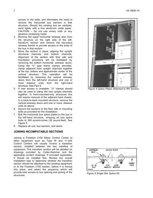
7. Bolt the horizontal bus splice plates to the bus in<br />
the left-hand structure, torquing all bus splice<br />
bolts to 360 pound-inches (30 pound-feet). See<br />
Figure 5.<br />
8. Replace all unit, bus barriers, and doors.<br />
JOINING INCOMPATABLE SECTIONS<br />
Joining a <strong>Freedom</strong> <strong>2100</strong> <strong>Motor</strong> <strong>Control</strong> <strong>Center</strong> to<br />
other equipment such as Type W and 11-300<br />
<strong>Control</strong> <strong>Center</strong>s will usually involve a transition<br />
section, installed between the two varieties of<br />
equipment. This transition section will be detailed on<br />
drawings provided by Cutler-Hammer and the<br />
applicable contact drawings. If provided separately,<br />
it should be installed first. Review the overall<br />
installation task to determine whether the transition<br />
section should be attached to the existing equipment<br />
or to the <strong>Freedom</strong> <strong>2100</strong> section, before it is moved<br />
into place, and select the sequence which will<br />
provide best access to bus splicing and joining of the<br />
structures.<br />
Figure 4 Splice Plates Attached to RH Section<br />
Figure 6 Single Bar Splice Kit