

Freedom 2100 Motor Control Center Installation - emsco
Freedom 2100 Motor Control Center Installation - emsco
Freedom 2100 Motor Control Center Installation - emsco

You also want an ePaper? Increase the reach of your titles
YUMPU automatically turns print PDFs into web optimized ePapers that Google loves.
5 I.B. 8926-1A<br />
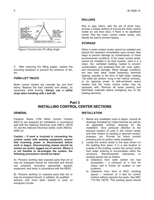
Figure 3 Correct Use Of Lifting Angle<br />
5. After removing the lifting angles, replace the<br />
mounting hardware to prevent the entrance of dirt,<br />
etc.<br />
FORK-LIFT TRUCK<br />
<strong>Motor</strong> control centers are normally top and front<br />
heavy. Balance the load carefully and steady, as<br />
necessary, while moving. Always use a safety<br />
strap when handling with a fork-lift.<br />
GENERAL<br />
ROLLERS<br />
Rod or pipe rollers, with the aid of pinch bars,<br />
provide a simple method of moving the motor control<br />
center on one floor level, if there is no significant<br />
incline. Roll the motor control center slowly, and<br />
steady the load to prevent tipping.<br />
STORAGE<br />
When a motor control center cannot be installed and<br />
placed into operation immediately upon receipt, take<br />
steps to prevent damage by condensation or harsh<br />
environmental conditions. If the motor control center<br />
cannot be installed in its final location, store it in a<br />
clean, dry, ventilated building, heated to prevent<br />
condensation, and protected from dirt, dust, water,<br />
and mechanical damage. When storage conditions<br />
are less than ideal, install temporary electrical<br />
heating, typically in the form of light bulbs, totaling<br />
150 watts per section, hung in the vertical wireway,<br />
or by applying power to self-contained space<br />
heaters that the motor control center may be<br />
equipped with. Remove all loose packing and<br />
flammable materials before energizing any of the<br />
heating elements.<br />
Part 3<br />
INSTALLING CONTROL CENTER SECTIONS<br />
<strong>Freedom</strong> Series <strong>2100</strong> <strong>Motor</strong> <strong>Control</strong> <strong>Center</strong>s<br />
(MCC’s) are designed for installation in accordance<br />
with both the National Electrical code (NEC), NFPA<br />
70, and the National Electrical Safety Code (NESC),<br />
ANSI C2.<br />
Caution – If work is involved in connecting the<br />
control center with existing equipment, ensure<br />
that incoming power is disconnected before<br />
work is begun. Disconnecting means should be<br />
locked out and/or tagged out of service. Where it<br />
is not feasible to de-energize the system, the<br />
following precautions should be taken:<br />
A) Persons working near exposed parts that are or<br />
may be energized should be instructed and should<br />
use practices (including appropriate apparel,<br />
equipment, and tools) in accordance with the NESC.<br />
B) Persons working on exposed parts that are or<br />
may be energized should, in addition, be qualified<br />
persons who have been trained to work on<br />
energized circuits.<br />
INSTALLATION<br />
1. Before any installation work is begun, consult all<br />
drawings furnished by Cutler-Hammer as well as<br />
all applicable contract drawings for the<br />
installation. Give particular attention to the<br />
physical location of units in the control center<br />
and their relation to existing or planned conduit,<br />
busways, etc. Provide for future conduit<br />
entrance prior to control center installation.<br />
2. Locate the control center in the area shown on<br />
the building floor plans. If in a wet location or<br />
outside of the building, protect the control center<br />
from water entering or accumulation within the<br />
enclosure. Recommended clearances or<br />
working spaces are as follows:<br />
a) Clearance from walls (where not rear<br />
accessible) – a minimum of ½ inch for<br />
indoor and 6 inches for outdoor or wet<br />
locations.<br />
b) Clearance from front of MCC (working<br />
space) – minimum of 3 feet for control<br />
centers without exposed live parts. See NEC<br />
110-16d. NOTE: This working space should