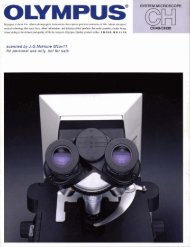
Olympus Biological Microscope Instructions BHTU (BH-2)
Olympus Biological Microscope Instructions BHTU (BH-2)
Olympus Biological Microscope Instructions BHTU (BH-2)

Create successful ePaper yourself
Turn your PDF publications into a flip-book with our unique Google optimized e-Paper software.
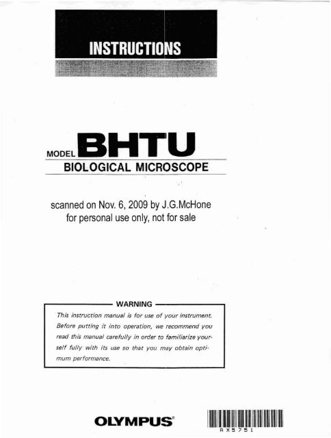
This instruction manual has been written for the use of the <strong>Olympus</strong> <strong>Biological</strong> <strong>Microscope</strong><br />
Model <strong><strong>BH</strong>TU</strong>. It is recommended that you read the manual carefully in order to familiarize<br />
yourself fully with the use of the microscope, so that you will obtain optimum performance.<br />
Observe the following points:<br />
• Operation<br />
IMPORTANT<br />
1. Always handle the microscope with the care it deserves, and avoid abrupt motions.<br />
2. Avoid the use and maintenance of the microscope in direct sunlight, high temperature and<br />
humidity, dust and vibration.<br />
3. Only use the tension adjustment ring for altering the tension of the coarse adjustment<br />
knobs. (Do not twist the two coarse adjustment knobs in opposite directions simultaneous<br />
Iy, as this will cause damage.)<br />
4. Make sure that the voltage selector switch on the bottom base of the microscope stand<br />
is set to conform with the local mains voltage.<br />
5. Ground the microscope in case there is no ground terminal in your mains line.<br />
• Maintenance<br />
,. Lenses must always be kept clean. Carefully wipe off oil or fingerprints deposited on the<br />
lens surfaces with gauze moistened with a small amount of xylene, alcohol or ether.<br />
2. Do not use organic solutions to wipe the surfaces of various components. Plastic parts,<br />
especially, should be cleaned with neutral detergent.<br />
3. Never disassemble the microscope for repair. Only authorized <strong>Olympus</strong> service personnel<br />
should make repairs.<br />
4. The microscope should be covered with the vinyl dust cover provided and stored in a place<br />
free from humidity and fungi.
I.<br />
II.<br />
III.<br />
STANDARD CONFIGURATIONS<br />
NOMENCLATURE<br />
ASSEMBLy.................<br />
CONTENTS<br />
IV. IDENTIFICATION AND FUNCTION OF VARIOUS COMPONENTS<br />
V.<br />
VI.<br />
VII.<br />
OPERATION<br />
A. Switching ON the Light Source<br />
IVoltage Adjustment and Light Intensity I<br />
I LP (Light Intensity Presetting) Switch I<br />
B. Placement of a Specimen Slide .<br />
I White Cover for Condenser<br />
I Cover Glass I<br />
I Specimen Slide I<br />
I Stage I<br />
C. Observation Tube<br />
1. Interpupillary Distance Adjustment<br />
2. Diopter Adjustment<br />
3. Light Path Selector<br />
D. Condenser Adjustment<br />
1. Condenser Centration<br />
IFiled Iris Diaphragm I<br />
I Aperture Iris Diaphragm<br />
E. Focusing Adjustment .<br />
1. Tension of Coarse Adjustment Knobs and Fine Adjustment<br />
I Use of Rubber Cap for Fine Adjustment Knob<br />
2. Pre-Focusing Lever<br />
F. Use of Immersion Objectives<br />
G. Photomicrography .<br />
OPTICAL DATA<br />
TROUBLESHOOTING GUIDE<br />
2<br />
3<br />
4<br />
6<br />
9<br />
9<br />
10<br />
13<br />
14<br />
15<br />
15<br />
17<br />
18
I. STANDARD CONFIGURATIONS<br />
<strong>Microscope</strong> stand<br />
Component<br />
with quintuple revolving nosepiece<br />
Observation tubes<br />
"",<br />
Model<br />
<strong><strong>BH</strong>TU</strong>·ll1 <strong><strong>BH</strong>TU</strong>-112 <strong><strong>BH</strong>TU</strong>·312<br />
<strong><strong>BH</strong>TU</strong>·F 1 1 1<br />
8 inocular tube <strong>BH</strong>2·B130 1 1 0<br />
Trinocular tube <strong>BH</strong>2·TR30 0 0 1<br />
Square mechanical stage with right-hand low <strong>BH</strong>2.SVR2<br />
drive coaxial controls and specimen holder<br />
1 1 1<br />
Swing-out condenser <strong>BH</strong>2·SC 1 1 1<br />
Halogen lamp holder LS·20H 1 1 1<br />
Halogen bulbs 6V20WHAL 2 2 2<br />
Objectives<br />
D Ach. 4X, D Ach. lOX, D Ach, 40X,<br />
1 0 0<br />
D Ach. lOOX (oil) each<br />
D Plan 4X, 0 Plan lOX, D Plan 40X<br />
0 1 1<br />
D Plan lOOX (oil) each each<br />
Eyepieces, paired WKlOX 1 1 1<br />
Photo eyepiece NFK3.3X 0 0 1<br />
Filter KB·4 1 1 1<br />
Immersion oil, bottled 1 1 1<br />
Vinyl dust cover 1 1 1<br />
2
II. NOMENCLATURE<br />
The Model <strong><strong>BH</strong>TU</strong> consists of various components and interchangeable accessories as shown in<br />
the photo below. A wide variety of combinations, standard or optional, is available according<br />
to your requirements.<br />
Objective<br />
Stage<br />
Condenser<br />
Eyepiece<br />
-<br />
3<br />
Observation tube<br />
Micoscope stand<br />
For biological use<br />
--<br />
--<br />
Halogen lamp<br />
holder<br />
LP (Light Intensity Presetting) switch
• Explanations in detai I<br />
9 Mounting the stage<br />
11 Loosen the stage clamping screw CD by<br />
rotating counterclockwise. (Fig. 1)<br />
2) Insert the stage into the mounting dove<br />
tail of the microscope stand slowly and<br />
lock with clamping screw.<br />
fJ Mounting the observation tube<br />
1) Loosen the clamping knob CD fully.<br />
(Fig.21 Pull spring-loaded clamping knob<br />
CD. This will cause the locating pin
Condenser height<br />
adjustment knob<br />
Pre- focusi ng lever<br />
Photo tube<br />
Line cord<br />
-<br />
7<br />
Diopter adjustment<br />
ring<br />
X-axis low drive<br />
control knob<br />
X excursion range:<br />
76 mm.<br />
Y-axis low drive<br />
control knob<br />
Y excursion range:<br />
50mm.<br />
Field iris diaphragm ring<br />
Arrow mark (0 ....... 0 indicates<br />
increase in diaphragm diameter.
D. Condenser Adjustment<br />
1. Condenser Centration<br />
1) Stop down the field iris diaphragm with<br />
knurled ring CD by rotating in the direction<br />
of the arrow. (Fig. 14)<br />
2) Use the condenser height adjustment<br />
knob ® to move the condenser up and<br />
down until an image of the field diaphragm<br />
can be seen clearly in the eyepieces.<br />
The rotation of the knob in the<br />
direction of the arrow lowers the condenser.<br />
Field iris<br />
diaphragm image Field of view<br />
Fig. 15<br />
Fig. 14<br />
3) Bring the field iris diaphragm image into the center of the field of view with the two condenser<br />
centering knobs ®. (Fig. 14)<br />
4) Widen the diameter of the iris diaphragm progressively. If the polygonal image of the iris<br />
diaphragm becomes inscribed in the field it means that the field diaphragm is centered.<br />
(Fig. 15)<br />
Field Iris Diaphragm I<br />
• The field iris diaphragm controls the diameter of the ray bundle impining on the specimen<br />
surface and therefore, by stopping down the field diaphragm until it is slightly<br />
larger than the field of view, it can reduce stray light, which in turn increases image definition<br />
and contrast.<br />
Aperture Iris Diaphragm I<br />
• In order to achieve opTimum objective performance, the opening of the aperture iris<br />
diaphragm should be matched to the numerical aperture of the objective in use. It is<br />
often preferable, however, to stop down the aperture diaphragm slightly more than indicated<br />
by the objective N.A. This will result in better image contrast, increased depth of<br />
focus and a flatter field.<br />
• After completing focus adjustment, remove<br />
one of the eyepieces from the observation<br />
tube and look into the empty<br />
eyepiece tube. As you stop down the<br />
aperture iris diaphragm, the image of the<br />
iris diaphragm can be seen in the objective<br />
pupil. Adjust the opening of the<br />
diaphragm to match the N.A. of the objective<br />
in use. If the specimen is low in<br />
contrast, it is recommended to stop down<br />
to 70% - 80% of the objective N.A. (Fig.<br />
161<br />
13<br />
Opening of the<br />
aperture diaphragm<br />
Objective exit pupil<br />
Fig. 16<br />
®<br />
70-80%<br />
20 - 30","
E Focus Adjustment<br />
1. Tension of Coarse<br />
Fine Adjustment.<br />
Adjustment Knobs and<br />
Although the tension of the coarse adjustment<br />
knobs has been already adjusted for<br />
optimum performance by the manufacturer.<br />
it is possible to personally adjust the tension<br />
of the coarse adjustment for either heavy or<br />
light movement depending on the operator's<br />
preference by rotating the tension adjust<br />
Fig. 18<br />
ment ring
F. Use of Immersion Objectives<br />
1) Focus the specimen with a low power objective.<br />
2) Put a drop of immersion oil on the specimen slide and the front lens of the immersion<br />
objective.<br />
3) Rotate the revolving nosepiece to bring the immersion objective into the light path, and<br />
focus with the fine adjustment knobs.<br />
NOTE: ill For immersion condensers such as an achromatic-aplanatic condenser or Abbe<br />
condenser, remove the specimen from the mechanical stage and place a drop of<br />
G. Photomicrography<br />
immersion oil on the front lens of the condenser. Then, place the specimen on<br />
the stage and slowly raise the condenser until firm contact with the underside of<br />
the specimen slide is made.<br />
® Care should be taken to prevent oil bubbles from forming in the oil film between<br />
condenser and specimen slide. If any bubbles appear, re-apply immersion oil,<br />
for these bubbles greatly deteriorate the lens performance.<br />
® After use. carefully wipe off the immersion oil deposited on the lens surfaces<br />
with gauze moistened with xylene. Never leave oil on the lens surfaces after use<br />
as oil remnants will seriously impair the perforrrance of the lens system.<br />
,<br />
The <strong>Olympus</strong> Photomicrographic Equipment Model PM-lOAO is uniquely qualified to be<br />
used with the <strong><strong>BH</strong>TU</strong> microscope for routine and advanced photomicrography. A separate,<br />
detailed instruction manual is available for the PM-lOAD camera system.<br />
For quick reference, however, you may want to refer to the following pointers when using<br />
the PM-lOAD.<br />
1. Photographic Eyepiece<br />
Use NFK photo eyepieces for photomicrography.<br />
Insert the eyepiece CD into the eyepiece tube<br />
of the photo tube. (Fig. 20)<br />
2. Mounting the Photographic Unit<br />
Slip the body of the photographic unit over the<br />
photo tube. Align the dots on photo tube and<br />
the PM- lOAD body and clamp the camera unit<br />
to the photo tube. (Fig. 211<br />
3. Setting the Light Path Selector<br />
Refer to section C.3. on page 12.<br />
15<br />
Fig. 20
4. Focusing Procedure<br />
Use the field of view eyepieces for focusing on the film plane. Each field of view eyepiece<br />
has a focusing front lens and a relide with 4 frames, each frame indicating the area covered<br />
by a specific power N FK photo eyepeice. (Fig. 22)<br />
The number at each frame indicates the<br />
magnification of the photo eyepiece. The<br />
image in the field of view eyepiece and the<br />
image on the film plane are in focus at the<br />
same time. Several type field of view eyepieces<br />
are available, according to the film<br />
size employed.<br />
Fig. 22<br />
Field of view eyepiece 35WHK10X PWHK10X 4X5WHK10X MHWHK10X<br />
Attachment camera<br />
35mm Back 3%" x 4%" 4" x 5" 16mm Bolex<br />
Polaroid Sheet Film or camera<br />
Back Polaroid Film 120 Roll Film<br />
Holder Holder<br />
1) Select the field of view eyepiece matching the camera bSlck in use and insert it into the<br />
right eyepiece tube of the trinocular tube, aligning locating groove and locating pin.<br />
2) While looking through the field of view eyepiece, rotate the eyepiece front lens in screw<br />
mount to focus on the double cross lines in the field. For sharp focusing with objectives<br />
4X or lower, the focusing magnifier FT is recommended on account of their considerable<br />
depth of focus.<br />
3) Bring the specimen detail to be photographed within the frame corresponding to the<br />
power of the NF K eyepiece in use and focus on the specimen with the microscope fine<br />
adjustment knobs. Make sure the light path selector knob on the observation tube is<br />
either on the white (V) or yellowijreen (eVI band.<br />
4) It is recommended to tighten the tension adjustment ring considerably to prevent the<br />
stage from dropping during long exposures.<br />
16
VII. TROUBLESHOOTING GUIDE<br />
If you are unable to obtain full performance from your microscope, please consult with the<br />
table below as pointers for troubleshooting.<br />
Phenomenon Cause Remedy<br />
1. Optical System<br />
a) With illuminator switched Field iris diaphragm IS not Open diaphragm to proper<br />
on, the field of view is opened sufficiently. diameter.<br />
dark.<br />
Condenser is lowered too Adjust condenser height.<br />
much.<br />
Light path selector lever is Push in lever up to CV or V<br />
pulled out to C position. position.<br />
b) Field of view is cut off or Light path selector lever is Click it into proper position<br />
illuminated irregularly. stopped midway. according to your purpose.<br />
Nosepiece is not clicked into Slightly rotate nosepiece until<br />
place. it cl icks into place.<br />
The power of objective used Choose a condenser to meet<br />
exceeds the illu'mination ca- your purpose.<br />
pacity of condenser.<br />
Condenser is not centered. Center condenser.<br />
Field irisdjaphragm is stopped Open diaphragm to proper<br />
down excessively. diameter.<br />
c) Dust or dirt is visible In Dust, etc. on light exit lens Remove dust, etc.<br />
the field of view.<br />
Dust on condenser top lens<br />
Clean front tenses.<br />
Dirty specimen<br />
Dust on eyepiece<br />
d) Excessive image contrast Condenser is lowered too Adjust condenser height.<br />
much.<br />
Aperture iris diaphragm is Open diaphragm to proper<br />
stopped down excessively. diameter.<br />
18
Phenomenon Cause Remedy<br />
3, Coarse and Fine Adjustments<br />
I aj Coarse adjustment knob is Tension adjustment ring is Loosen ring properly.<br />
too tight. tightened too much.<br />
Users is trying to raise stage Unlock pre-focusing lever.<br />
above the focusing limit with<br />
pre-focusing lever engaged.<br />
bl Stage drops or specimen Tension adjustment ring is Tighten ring properly.<br />
goes out of focus during too loose.<br />
observation due to slipping<br />
fine adjustment knobs.<br />
c) Stage cannot be raised to Pre-focusing lever is engaged Unlock lever.<br />
the upper limit. in lower than focusing posi-<br />
tion.<br />
dl Stage cannot be lowered Condenser mount is lowered Raise condenser.<br />
to the lower limit. too much.<br />
e) Objective front lens hits Specimen is placed on stage Reverse specimen.<br />
specimen before coming upside down..<br />
into focus.<br />
4, Observation Tubes<br />
al Incomplete binocular vi- Interpupillary distance is not Correct the interpupillary dissian.<br />
correctly adjusted. tance.<br />
5, Stage<br />
Diopter adjustment is incom- Complete the diopter adjustplete,<br />
ment.<br />
Right and left eyepieces are Use a pair of matched eyenot<br />
matched. pieces.<br />
User is unaccustomed to bi- Prior to looking into the binocular<br />
vision. nocular observation tube, look<br />
at a far away object.<br />
a) Image easily goes out of Stage is not correctly locked. Clamp stage securely.<br />
focus when you touch the<br />
stage.<br />
bl Specimen stops midway Specimen is not correctly poon<br />
the east-west traverse. sitioned.<br />
20<br />
Adjust specimen pOSitioj