Seal-Lok™ O-Ring Face Seal Tube Fittings
Seal-Lok™ O-Ring Face Seal Tube Fittings
Seal-Lok™ O-Ring Face Seal Tube Fittings

You also want an ePaper? Increase the reach of your titles
YUMPU automatically turns print PDFs into web optimized ePapers that Google loves.
4300 Catalog<br />
Identification<br />
To differentiate metric <strong>Seal</strong>-Lok from standard (inch) <strong>Seal</strong>-Lok,<br />
the following identification features have been incorporated in<br />
the design:<br />
• Straight connectors (straight studs) have a short length<br />
of turn diameter with a small groove machined in it’s<br />
middle, as seen in Fig. A4.<br />
• The locknuts on shaped connectors (stud elbows, tees<br />
and crosses) have a similar turn diameter adjacent to the<br />
washer, without a groove, as seen in Fig. A4.<br />
• The sleeve is identified by a small groove machined on<br />
its large diameter as shown in Fig. A5.<br />
Versatility<br />
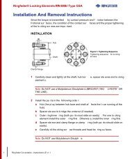
The <strong>Seal</strong>-Lok fitting is very versatile in that it can be used with<br />
inch and metric tubing, as well as hose (see Fig A6).<br />
The following example illustrates the options with a ½" (-8)<br />
<strong>Seal</strong>-Lok fitting:<br />
• ½" fitting and ½" nut can connect to ½" tubing using the<br />
½" sleeve.<br />
• ½” fitting and ½" nut can connect to 12 mm tubing using<br />
12 mm sleeve.<br />
• Without nut and sleeve, ½" fitting can connect to hose.<br />
The process also works in reverse. A metric <strong>Seal</strong>-Lok fitting<br />
and metric nut can connect to inch tubing by simply using the<br />
inch sleeve.<br />
<strong>Tube</strong> Wall Thickness<br />
Recommended min/max tube wall thicknesses for inch and metric<br />
<strong>Seal</strong>-Lok are provided in Tables A2 and A3, respectively. When<br />
using the braze method, all tube wall thicknesses can be used.<br />
For Parflange min/max tube wall thickness range, please refer<br />
to page S26 for tooling availability.<br />
With any fitting, proper assembly and installation is critical to its<br />
success. Please refer to pages T13-T18 for the proper assembly<br />
and installation procedures for the <strong>Seal</strong>-Lok fitting.<br />
Dimensions and pressures for reference only, subject to change.<br />
A7<br />
<strong>Seal</strong>-Lok O-<strong>Ring</strong> <strong>Face</strong> <strong>Seal</strong> <strong>Tube</strong> <strong>Fittings</strong><br />
Body<br />
Inch Sleeve and <strong>Tube</strong><br />
Metric Sleeve and <strong>Tube</strong><br />
Hose<br />
Fig. A6 — <strong>Seal</strong>-Lok Works with Inch or Metric <strong>Tube</strong> and Hose<br />
Size<br />
Steel, Alloy Steel, St. Steel,<br />
Copper, Monel<br />
O.D. Dash<br />
SAE O-<strong>Ring</strong><br />
Inches Number <strong>Face</strong> <strong>Seal</strong> <strong>Seal</strong>-Lok<br />
1/4 -4 .020 – .083<br />
3/8 -6 .020 – .109<br />
1/2 -8 .028 – .148<br />
5/8 -10 .035 – .134<br />
3/4 -12 .035 – .148<br />
7/8 -14 .035 – .156<br />
1 -16 .035 – .188<br />
1 1/4 -20 .049 – .220<br />
1 1/2 -24 .049 – .250<br />
2 -32 .058 – .250<br />
Table A2 — Recommended Min./Max. <strong>Tube</strong> Wall<br />
Thickness for Inch <strong>Seal</strong>-Lok<br />
Steel, Alloy Steel,<br />
Stainless Steel,<br />
Copper, Monel<br />
O.D. Size Wall Thickness Used With<br />
in mm in mm Fitting Size<br />
6 .5 - 2.25 -4<br />
8 1.0 - 2.5 -6<br />
10 1.0 - 3.0 -6<br />
12 1.0 - 3.5 -8<br />
14 1.0 - 4.0 -10<br />
15 1.0 - 3.0 -10<br />
16 1.0 - 3.0 -10<br />
18 1.0 - 3.0 -12<br />
20 1.5 - 4.0 -12<br />
22 1.0 - 3.0 -16<br />
25 2.0 - 5.0 -16<br />
28 1.5 - 5.0 -20<br />
30 2.0 - 5.0 -20<br />
32 2.0 - 2.5 -20<br />
35 2.0 - 6.0 -24<br />
38 2.5 - 7.0 -24<br />
Table A3 — Recommended Min./Max. <strong>Tube</strong><br />
Wall Thickness for Metric <strong>Seal</strong>-Lok<br />
Nut<br />
Parker Hannifin Corporation<br />
<strong>Tube</strong> <strong>Fittings</strong> Division<br />
Columbus, Ohio<br />
http://www.parker.com/tfd