Y-Cable Splitter Job Aid - Adtran
Y-Cable Splitter Job Aid - Adtran
Y-Cable Splitter Job Aid - Adtran

Create successful ePaper yourself
Turn your PDF publications into a flip-book with our unique Google optimized e-Paper software.
Product P/N: 1184015L1<br />
DESCRIPTION<br />
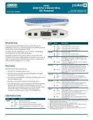
The Y-<strong>Cable</strong> <strong>Splitter</strong> connects two optical devices to a single fiber<br />
span, or routes a single optical signal onto two different fibers.<br />
The Y-cable can only transmit one signal at a time (does not<br />
provide a multplexing function), so use with two optical devices<br />
is best accomplished in a redundant configuration where only<br />
one device is online at any one time.<br />
The Y-cable is bi-directional and can be used in either the<br />
Transmit (Tx) or Receive (Rx) direction, at either end of a fiber<br />
span, depending on the function it is to provide.<br />
Y-<strong>Cable</strong> <strong>Splitter</strong><br />
The Y-cable supports the following features:<br />
♦ Fiber leads are 1 meter each in length<br />
♦ SC connectors<br />
♦ Optical loss of 0.5 dB<br />
Issue Date: 0804<br />
Document P/N: 61184015L1-22A<br />
CONFIGURATION OPTIONS<br />
The Y-cable can be used in any application where it is desirable<br />
to split an optical source. The following two configurations are<br />
provided as examples of possible applications:<br />
♦ Single span redundancy<br />
♦ Test kit lead<br />
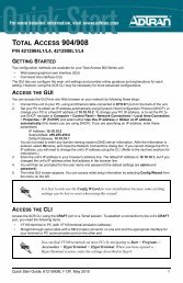
Single Span Redundancy<br />
When an existing optical path is upgraded from a stand-alone configuration to a redundant configuration, using Y-cables can<br />
eliminate the need to run new fiber spans for the Protect modules. Installing Y-cables at each end of the existing spans allows<br />
Working and Protect modules to share the same fibers.<br />
Stand-alone Configuration<br />
STATUS<br />
OPTICS<br />
DS3-1<br />
DS3-2<br />
DS3-3<br />
ACO<br />
STATUS<br />
OPTICS<br />
DS3-1<br />
DS3-2<br />
DS3-3<br />
ACO<br />
APS TEST ACO<br />
ENABLE<br />
Rx<br />
Tx<br />
APS TEST ACO<br />
ENABLE<br />
Tx<br />
Rx<br />
CRAFT<br />
CRAFT<br />
OPTI-3<br />
1184002L1V<br />
OPTI-3<br />
1184002L1V<br />
1184003L1<br />
1184003L1<br />
RMC RMC<br />
RMC RMC<br />
Far End<br />
Near End<br />
Redundant Configuration<br />
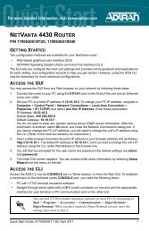
Test Kit Lead<br />
Installing a Y-cable between the existing fiber and optical device enables a test kit to be attached to the second lead of the Y-cable.<br />
In this configuration, a test kit can be attached without disrupting traffic.<br />
Without Test Kit<br />
STATUS<br />
OPTICS<br />
DS3-1<br />
DS3-2<br />
DS3-3<br />
ACO<br />
STATUS<br />
OPTICS<br />
DS3-1<br />
DS3-2<br />
DS3-3<br />
ACO<br />
APS TEST ACO<br />
ENABLE<br />
Rx<br />
Tx<br />
APS TEST ACO<br />
ENABLE<br />
Tx<br />
Rx<br />
CRAFT<br />
CRAFT<br />
OPTI-3<br />
1184002L1V<br />
OPTI-3<br />
1184002L1V<br />
1184015L1<br />
1184003L1<br />
1184003L1<br />
STATUS<br />
OPTICS<br />
DS3-1<br />
DS3-2<br />
DS3-3<br />
ACO<br />
Rx<br />
Tx<br />
STATUS<br />
OPTICS<br />
DS3-1<br />
DS3-2<br />
DS3-3<br />
ACO<br />
APS TEST ACO<br />
ENABLE<br />
APS TEST ACO<br />
ENABLE<br />
Tx<br />
Rx<br />
CRAFT<br />
CRAFT<br />
OPTI-3<br />
1184002L1V<br />
RMC RMC<br />
OPTI-3<br />
1184002L1V<br />
RMC RMC<br />
Rx<br />
Tx<br />
STATUS<br />
OPTICS<br />
DS3-1<br />
DS3-2<br />
DS3-3<br />
ACO<br />
STATUS<br />
OPTICS<br />
DS3-1<br />
DS3-2<br />
DS3-3<br />
ACO<br />
STATUS<br />
OPTICS<br />
DS3-1<br />
DS3-2<br />
DS3-3<br />
ACO<br />
STATUS<br />
OPTICS<br />
DS3-1<br />
DS3-2<br />
DS3-3<br />
ACO<br />
APS TEST ACO<br />
ENABLE<br />
APS TEST ACO<br />
ENABLE<br />
CRAFT<br />
CRAFT<br />
OPTI-3<br />
1184002L1V<br />
Tx<br />
Rx<br />
OPTI-3<br />
1184002L1V<br />
1184003L1<br />
#4 #3<br />
#1 #2<br />
1184003L1<br />
Rx Tx<br />
Tx<br />
STATUS<br />
OPTICS<br />
DS3-1<br />
DS3-2<br />
DS3-3<br />
ACO<br />
STATUS<br />
OPTICS<br />
DS3-1<br />
DS3-2<br />
DS3-3<br />
ACO<br />
APS TEST ACO<br />
ENABLE<br />
APS TEST ACO<br />
ENABLE<br />
Working Module Protect Module<br />
With Test Kit<br />
Test<br />
Kit<br />
APS TEST ACO<br />
ENABLE<br />
Tx<br />
APS TEST ACO<br />
ENABLE<br />
Rx<br />
CRAFT<br />
CRAFT<br />
OPTI-3<br />
1184002L1V<br />
Tx<br />
Rx<br />
OPTI-3<br />
1184002L1V<br />
1184003L1<br />
1184003L1<br />
STATUS<br />
OPTICS<br />
DS3-1<br />
DS3-2<br />
DS3-3<br />
ACO<br />
Rx<br />
Tx<br />
STATUS<br />
OPTICS<br />
DS3-1<br />
DS3-2<br />
DS3-3<br />
ACO<br />
APS TEST ACO<br />
ENABLE<br />
APS TEST ACO<br />
ENABLE<br />
Tx<br />
Rx<br />
CRAFT<br />
CRAFT<br />
OPTI-3<br />
1184002L1V<br />
Rx<br />
CRAFT<br />
CRAFT<br />
RMC RMC<br />
OPTI-3<br />
1184002L1V<br />
RMC RMC<br />
OPTI-3<br />
1184002L1V<br />
RMC RMC<br />
OPTI-3<br />
1184002L1V<br />
RMC RMC
Product P/N: 1184015L1<br />
PRE-INSTALLATION<br />
Inspect the Y-cables. If damaged, file a claim with the carrier and<br />
then contact ADTRAN Customer Support.<br />
Identify the fiber leads on the Y-cables to be used for Tx and Rx<br />
as necessary for the intended application.<br />
INSTALLATION<br />
The following installation procedure is an example of how to<br />
install four Y-cables into a legacy, stand-alone configuration<br />
when upgrading to a redundant configuration. Refer to “Single<br />
Span Redundancy” for details.<br />
NOTE: Although the OPTI-3 is cited in this procedure, the Y-cable<br />
can be used with most ADTRAN optical equipment.<br />
CAUTION: This procedure interrupts traffic. Near-end and<br />
far-end upgrades should be coordinated to minimize<br />
the resulting loss of service.<br />
This procedure involves two modules and two Y-cables<br />
at each end of the fiber spans. Make certain each item<br />
is clearly identified.<br />
To upgrade from stand-alone to redundant, using Y-cables<br />
instead of two new fiber spans, complete the following steps:<br />
1. Remove the stand-alone module from the legacy system.<br />
2. Disconnect the Tx fiber from the legacy module.<br />
NOTE: The legacy module becomes the Working module in the<br />
redundant configuration.<br />
3. Connect the single-fiber of Y-cable #1 to the Tx fiber.<br />
4. Connect one of the dual-side fibers of Y-cable #1 to the<br />
Working module Tx jack.<br />
5. Disconnect the Rx fiber from the Working module.<br />
6. Connect the single-fiber of Y-cable #2 to the Rx fiber.<br />
7. Connect one of the dual-side fibers of Y-cable #2 to the<br />
Working module Rx jack.<br />
8. Re-install the Working module.<br />
NOTE: If all connections have been made properly, the module<br />
should turn up as normal.<br />
9. Connect the second Tx fiber (Y-cable #1) and Rx fiber<br />
(Y-cable #2) to the new, Protect module.<br />
10. Install the Protect module.<br />
11. Complete the steps at the far end. Repeat steps 1 – 10,<br />
substituting Y-cable #3 for Y-cable #1, and Y-cable #4 for<br />
Y-cable #2 in the instructions.<br />
Y-<strong>Cable</strong> <strong>Splitter</strong><br />
Warranty: ADTRAN will replace or repair this product within the warranty period if it does not meet its<br />
published specifications or fails while in service. Warranty information can be found online at<br />
www.adtran.com/warranty.<br />
©2008 ADTRAN, Inc. All Rights Reserved.<br />
MAINTENANCE<br />
The Y-cable does not require routine hardware maintenance for<br />
normal operation. ADTRAN does not recommend that repairs be<br />
attempted in the field. Repair services may be obtained by<br />
returning the defective unit to ADTRAN. Refer to “Warranty” for<br />
further information. Field support for software is provided<br />
through upgrade facilities.<br />
C A U T I O N !<br />
SUBJECT TO ELECTROSTATIC DAMAGE<br />
OR DECREASE IN RELIABILITY.<br />
HANDLING PRECAUTIONS REQUIRED.<br />
Issue Date: 0804<br />
Document P/N: 61184015L1-22A<br />
PRICING AND AVAILABILITY 800.827.0807<br />
TECHNICAL SUPPORT 800.726.8663<br />
RETURN FOR REPAIR 256.963.8722<br />
*61184015L1-22A*