IEPC-2011-001
IEPC-2011-001
IEPC-2011-001

Create successful ePaper yourself
Turn your PDF publications into a flip-book with our unique Google optimized e-Paper software.
Vernier Propulsion System for Small Earth<br />
Remote Sensing Satellite “Canopus-V”.<br />
<strong>IEPC</strong>-<strong>2011</strong>-<strong>001</strong><br />
Presented at the 32nd International Electric<br />
Propulsion Conference,<br />
Wiesbaden Germany<br />
September 11-15, <strong>2011</strong><br />
Alexander V. Gorbunov 1. , Vladimir P. Khodnenko 2. , Alexander V. Khromov 3<br />
Federal Governmental Unitary Research and Production Enterprise – All Russian Research Institute of<br />
Electromechanics with Plant named after A.G. Iosifian, VNIIEM: POB 496, Glavpochtamt, Moscow, 101000, Russia<br />
Vyacheslav M. Murashko 4. , Alexander I. Koryakin 5 , Valery S. Zhosan 6 , Gennady S. Grikhin 7 .<br />
FSUE Experimental Design Bureau “Fakel” (OKB “Fakel”): 181. Moskovsky avenue, Kaliningrad Region, 236<strong>001</strong>,<br />
Russia<br />
and<br />
Vladimir N. Galayko 8. Nikolay M. Katasonov 9<br />
JSC Scientific & Industrial Centre “Polus”: 56 “в”, Kirov avenue, Tomsk, 634050, Russia<br />
Abstract: The satellite constellation of perspective Space Complex (SC) of operative<br />
monitoring of technogenic and natural emergency situations “Canopus-V” comprises<br />
two “Canopus-V” satellites located in one plane with phase difference of 180° and on<br />
510km altitude orbit. The “Canopus-V” SC includes a Vernier Propulsion System (VPS)<br />
based on SPT-50 Stationary Plasma Thruster. The paper describes a structure, main<br />
characteristics of VPS, its block diagram, detailed conversion and control system PPU-<br />
CV providing power supply and operation logic for VPS.<br />
I Introduction<br />
The future-oriented Space Complex of operative monitoring of technogenic and natural emergency situations<br />
“Canopus-V” is designed to fulfill the following main tasks:<br />
− monitoring of technogenic and natural emergency situations including hydrometeorological acts of<br />
nature<br />
− detection of forest fires, major release of polluting matters into natural environment<br />
− monitoring of agricultural activities, natural resources (including aquatic and nearshore resources<br />
monitoring)<br />
− land utilization<br />
− operating supervision of designated areas of earth's surface in the interest of different sectors of the<br />
national economy.<br />
____________________________<br />
1 Dep. General Designer, e-mail: vniiem.gor@mail.ru<br />
2 Chief Scientific Officer, e-mail: vniiem.gor@mail.ru<br />
3 Head of laboratory, e-mail: vniiem.gor@mail.ru<br />
4 General Designer, e-mail: fakel@gazinter.net<br />
5 Dep. General Designer, e-mail: fakel@gazinter.net<br />
6 Head of Department, e-mail: fakel@gazinter.net<br />
The 32nd International Electric Propulsion Conference, Wiesbaden, Germany<br />
September 11-15, <strong>2011</strong>
7 Dep. Head of Department, e-mail: fakel@gazinter.net<br />
8 Head of laboratory, e-mail: polus@online.tomsk.net<br />
9 Chief Scientific Officer, e-mail: polus@online.tomsk.net<br />
The space complex “Canopus-V” includes a constellation consisting of two “Canopus-V” SC on one plane at<br />
180° phase position.<br />
The constellation operating on sun-synchronous orbit of 510km altitude requires total expenditures of reference<br />
speed for seven years operation life of SC.<br />
The Vernier Propulsion System (VPS) of “Canopus-V” is designed for:<br />
- initial error correction during the satellite injection into orbit<br />
- generation of a satellite constellation with phase difference φ=180°<br />
- orbit correction to compensate for atmospheric braking<br />
- orbit correction to maintain the satellite angular location based on the argument of latitude.<br />
II Necessary thrust characteristics of SC orbit correction.<br />
According to estimates the necessary total impulse to carry out the respective kinds of corrections of SC orbital<br />
parameters are 30.59 kNs (33.65 kNs taking into account 10% for spread propulsive effort as for absolute<br />
magnitude). The values of correction parameters and necessary thrust characteristics of SC orbit correction are<br />
shown in Table 1.<br />
Table 1. Correction parameters and thrust characteristics for “Canopus-V” SC for orbit correction of 7 years.<br />
Parameters correction Parameters correction value Necessary thrust pulse, kNs<br />
Initial period of revolution, ∆T 4 s 0.82<br />
Initial inclination, ∆i 2’ 2.16<br />
Initial eccentricity, ∆e 0.0008 1.48<br />
Initial perigee argument, ω 40° 2.09<br />
Moving apart in phase φ=180° 5 s 1.04х2<br />
Period support, ∆T 48.2 s 9.88<br />
Inclination support, ∆i 7’ 7.35<br />
Orbital plane position correction 4.8’ 4.73<br />
Total impulse, kNs 30.59 (33.65 inclusive 10% propulsive effort spread)<br />
III Comparing various types of VPS<br />
Various types of VPS models (both foreign and Russians) were considered on the assumption of total impulse<br />
Table 2 represents characteristics of various types of VPS with respect to “Canopus-V” SC.<br />
Table 2. VPS characteristics<br />
VPS<br />
parameters<br />
Total impulse,<br />
kNs<br />
Specific<br />
impulse, s<br />
Thrust, G<br />
(mN)<br />
Power<br />
consumption,<br />
SSTL<br />
Xenon<br />
VPS<br />
SSTL<br />
Water<br />
VPS<br />
NIIEM<br />
Ammonical<br />
VPS<br />
VPS type<br />
NIIPME<br />
Ftoroplast VPS<br />
with Ablative<br />
Pulsed Plasma<br />
Thruster (APPT)<br />
Experimental<br />
Design Bureau<br />
“Fakel”<br />
Hydrazine VPS<br />
with<br />
Thermocatalytic<br />
Thruster (TCT)<br />
Experimental<br />
Design Bureau<br />
“Fakel”<br />
Xenon VPS<br />
with Stationary<br />
Plasma Thruster<br />
(SPT)<br />
40 40 40 40 40 40<br />
60 152 164 1700 208 900<br />
1.0 … 4.0<br />
(10 - 40)<br />
4.5<br />
(45)<br />
4.0 (40)<br />
0.25 … 0.35 (2.5<br />
– 3.5)<br />
10 (100) 1.5 (15)<br />
80 100 100 100 ~ 30 ~ 300<br />
2The 32nd International Electric Propulsion Conference, Wiesbaden, Germany<br />
September 11-15, <strong>2011</strong>
W<br />
Propellant<br />
mass per<br />
thrust, kg<br />
67 27 24.4 2.5 19.2 4.4<br />
Total mass, kg 90 40 36,5 17.5 45 25<br />
IV “Canopus-V” SC Vernier Propulsion System<br />
The VPS based on Stationary Plasma Thrusters SPT-50 1,2,3 developed by OKB “Fakel” (Kaliningrad, Russia)<br />
was chosen for “Canopus-V” SC taking into account the achieved characteristics and grade of experience in natural<br />
conditions.<br />
Main characteristics of VPS<br />
Parameter Value<br />
Power consumption, W 317<br />
Nominal thrust, G (mN) 1.4 (14)<br />
Nominal thrust specific impulse, s 850<br />
Operating life, hour 800<br />
Number of firings 2000<br />
VPS dry mass, kg 19.2<br />
Loaded xenon mass, kg 5.2<br />
Total warranty period, years 10<br />
Lifetime, years 7<br />
The VPS of “Canopus-V” SC contains the following units:<br />
− Two Thrusters SPT-50 (Fig. 1), one of which is a backup, providing a corrective pulse thrust<br />
− Two Xenon Flow Controller XFC-50 (Fig. 2) to supply xenon to main and redundant thrusters SPT-50<br />
respectively<br />
− Flow Control Unit – FCU (the same Xenon Feed Unit) (Fig. 3) containing the main and backup branches to<br />
conduct xenon to XFC-50<br />
− Xenon Storage System (unit) XSS (Fig. 4) providing storage and supply of stock-pile into FCU<br />
− Power Processing Unit PPU-CV designed for power supply and control of VPS units.<br />
Two SPT-50 thrusters, two gas control units, xenon feed unit, interunit pipes with receiver are structurally<br />
united in SC Orbit Correction Unit (Fig. 6).<br />
Fig.1. Stationary Plasma Thruster (SPT-50). Fig.2. Xenon Flow Controller (XFC-50).<br />
3The 32nd International Electric Propulsion Conference, Wiesbaden, Germany<br />
September 11-15, <strong>2011</strong>
Fig.3. Flow Control Unit - FCU (Xenon Feed Unit) Fig.4. Xenon Storage System (XSS).<br />
Fig.5. Power Processing Unit (PPU-CV) Fig.6. Orbit Correction Unit (OCU).<br />
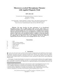
Figure 7 represents the VPS block diagram. It should be noted, that PPU-CV has only electrical connections to<br />
the sells shown in the scheme and as an individual unit is not shown.<br />
XSS contains two xenon tanks (Tnk1 and Tnk2), two pyrotechnic valves (PV1 and PV2) installed in parallel in<br />
the xenon supply tract, heat sensor (HS) and Filler Neck (FN). The xenon is supplied from XSS to FCU after PV1<br />
and PV2 pyrotechnic valves blowing up along interunit piping of high pressure (HPP1) including the Test Neck<br />
(TN1).<br />
FCU contains two independent xenon feed lines and herewith only one of them is operating, the second line is a<br />
redundant. Each FCU branch has an Electric xenon supply Valve EV1 (EV3) fulfilling a cut-off function,<br />
mechanical Pressure Regulator PR1 (PR2) and a supply valve EV2 (EV4). The mechanical pressure regulator is to<br />
lower xenon pressure from changeable high at input (~110kg/cm²) to low constant at output (1 – 6 kg/cm²). Each<br />
pressure regulator PR1 (PR2) has a heater EV providing a necessary thermal mode and a telemetric heat sensor HS1<br />
(HS2). A high pressure telemetric sensor HPTS1 (HPTS3) is mounted in each xenon feed line behind the cut-off<br />
valve at pressure regulator PR1 (PR2) input.<br />
TN1<br />
HPP1<br />
F<br />
from PPU<br />
"PV1"<br />
"PV2"<br />
from PPU<br />
"FN"<br />
Tnk1<br />
"XSS"<br />
"HS"<br />
o<br />
t<br />
f rom PPU f rom PPU from PPU<br />
EV1<br />
EV<br />
EV2<br />
"PR1"<br />
f rom PPU<br />
EV3<br />
P HPTS1 t "HS1"<br />
o<br />
Tnk2<br />
TM<br />
TM TM<br />
TM<br />
from PPU<br />
t o<br />
EV4<br />
P HPTS3 "HS2" P LPTS4<br />
EV<br />
f rom PPU<br />
"PR2"<br />
P LPTS2<br />
"FCU"<br />
LPP2<br />
TN2<br />
"Input"<br />
from PPU<br />
"XFC1"<br />
from PPU<br />
EV1<br />
EV2<br />
LPP3<br />
CC FR2<br />
"C"<br />
from PPU<br />
FR1<br />
from PPU<br />
EV3<br />
"XFC2"<br />
"A"<br />
LPP4<br />
LPP5<br />
LPP6<br />
from PPU<br />
Catode C1<br />
Filament C1<br />
Ignition 1<br />
Catode<br />
Magnite<br />
- Discharge<br />
Magnite<br />
+ Discharge<br />
4The 32nd International Electric Propulsion Conference, Wiesbaden, Germany<br />
September 11-15, <strong>2011</strong><br />
EV<br />
"C1"<br />
MC2<br />
Ct<br />
IE<br />
MC4<br />
MC3<br />
MC1<br />
At<br />
"T1"<br />
"T2"
Fig.7. “Canopus-V” SC VPS block diagram.<br />
A Low Pressure Telemetry Sensor LPTS2 (LPTS4) is mounted at Pressure Regulator output PR1 (PR2). The<br />
xenon is supplied from FCU to XFC-50 (XFC1, XFC2) via low pressure InterUnit Piping (LPP2) including the Test<br />
Neck (TN2).<br />
The xenon flow controller XFC-50 (XFC1, XFC2) supplies xenon to anode (А) and cathode tracts of SPT-50<br />
thruster (T1, T2) with required value of xenon consumption via interunit pipes LPP3 and LPP4 (LPP5 and LPP6).<br />
Each XFC -50 xenon supply tract has a supply valve EV1 at input and cutoff valves EV2 and EV3 at output.<br />
The Consumption Controller (CC) and Flow Restrictors (FR1 and FR2) of XFC-50 provide a necessary<br />
consumption level of xenon to Anode (A) and Cathode (C) of the SPT-50 thruster in dependence of<br />
discharge current value. The SPT-50 thruster (T1, T2) provides creation of corrective burst of power by means of<br />
interaction of plasma charged particles with mutually perpendicular lengthwise electrical and radial magnetic fields<br />
created in coaxial channel of discharge chamber of the thruster. Each SPT-50 contains cathode (C) and anode (А)<br />
packs. The cathode pack has a proper cathode , heater (H) and igniting electrode (IE). The anode pack has a<br />
proper anode and magnet system coils (MC1 … MC4).<br />
Figure 8 represents a general view of “Canopus-V” SC with VPS mounted on it.<br />
5The 32nd International Electric Propulsion Conference, Wiesbaden, Germany<br />
September 11-15, <strong>2011</strong>
Fig.8. “Canopus-V” with VPS<br />
It should be noted, that PPU-CV is an important element of VPS supplying power and logic of operation and is<br />
worth to be described in more details.<br />
The PPU-CV is manufactured in accordance with electro-pneumatic principal scheme of VPS and consists of<br />
functional modular constructs (Fig. 9).<br />
Fig.9. PPU-CV block diagram.<br />
Switcher Power Supply Modules (SPSM), Conversion Modules (CM) and xenon supply control modules<br />
(XSCM) are general and function when Thrusters T1 and T2 operate. A discharge supply module (DSM), Thruster<br />
Igniting Module (TIM), and XFC Control Unit (XFCCU) with number 1 serve only for thruster T1 operation, with<br />
number 2 – only for thruster T2.<br />
The PPU-CV is based on a launch system and power supply with a multiplex voltage converter and general<br />
control circuit on base of Pulse Duration Modulation Controller 4 (PDMC). The PDMC provides stabilization for<br />
each channel:<br />
− cathode heater current ;<br />
6The 32nd International Electric Propulsion Conference, Wiesbaden, Germany<br />
September 11-15, <strong>2011</strong>
− discharge voltage at stabilized consumption of working agent;<br />
− magnetic coils additional current .<br />
Via the discharge channel the same PDM controller limits the discharge current in anomalous<br />
conductivity of discharge channel mode at the preset level as per functional dependence:<br />
As far as the cathode heating and operation discharge mode operate in different time, the stabilization ,<br />
and is provided by change of durability of inverter ac voltage pulses generated by general PDM<br />
controller according to relations:<br />
where is a relative durability of inverter voltage pulses<br />
f –voltage frequency conversion<br />
- VPS power supply relative voltage<br />
– cathode heater relative resistance<br />
– relative conductivity of discharge channel in anomalous mode.<br />
The minimal conductivity of the discharge channel in anomalous mode is determined by ratios:<br />
At anomalous mode of conductivity, the requirements to stability are not presented.<br />
The stabilization of additional current of magnetic coils in function from is provided at stabilization,<br />
but in dependence of change of summarized resistance of magnetic coils by uninterruptable current stabilizer.<br />
Thanks to the mentioned additional current the pulses of magnetic coils are minimal.<br />
The power supply of the heater, cathode discharge and magnetic coils of each thruster is performed from<br />
separate voltage converter (VC) with three channel output produced as per pseudo two-cycle scheme from singlecycle<br />
converters. The set output power of consumers in transient mode of thruster igniting is:<br />
where 0.65 is a discharge current index corresponding to thruster operation mode starting.<br />
The summarized output power of the converter in operation mode of the thruster:<br />
In PPU-CV the nominal values of output power of three channel converter in the start-up mode as well as in<br />
operational one are respectively 250W and 242W.<br />
7The 32nd International Electric Propulsion Conference, Wiesbaden, Germany<br />
September 11-15, <strong>2011</strong>
It should be noted that the usage of multichannel voltage conversion in PPU-CV with common PDM controller<br />
combining stabilization functions of power supply parameters of each output of the converter enabled to provide<br />
acceptable mass and dimensions for PPU-CV.<br />
The pressure regulators heaters of xenon storage and supply system of XSSS and electric valves of VPS in<br />
holding mode are supplied with electric power from an auxiliary power source made according to the self-oscillator<br />
scheme with multichannel output. The current for thermal throttle of standby and operation modes is generated by<br />
individual converters - current controllers.<br />
Along with the concordance of VPS power consumers the PPU-CV receives and executes 22 commands,<br />
generates and transmits analog (10) and signal telemetric data (6).<br />
References<br />
___________________________<br />
1 Andropov N.N., Kazeev M.H., Khodnenko V.P. “High Thrust APPTs for Spacecraft Orbit Control”, 31th<br />
International Electric Propulsion Conference, University of Michigan, USA, September 20-24, 2009 # <strong>IEPC</strong>-2009-<br />
248.<br />
2 Kim V., Khodnenko V.P., Popov G.A., Semenkin A.V at all “Overview of Electric Propulsion Activity in Russia”<br />
30th Internacional Electric Propulsion Conference, Florence, Italy, September 17-20, 2007, <strong>IEPC</strong>-2<strong>001</strong>-275.<br />
3 rd Arkhipov B., Kim V., Koryakin A. at all “Small SPT Development and Tests” Proceedings of the 3 International<br />
Conference on Spacecraft Propulsion, Cannes, France, 2000, p.p. 399-401.<br />
4 Katasonov N.M. Electric jet plasma thruster igniting and power supply system. Pat. 21626223 R.F. Inventions.<br />
2003 №3.<br />
8The 32nd International Electric Propulsion Conference, Wiesbaden, Germany<br />
September 11-15, <strong>2011</strong>