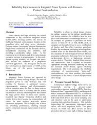
Paul Slebodnick, James Tagert, Bruce N. Nelson, Darren C ...
Paul Slebodnick, James Tagert, Bruce N. Nelson, Darren C ...
Paul Slebodnick, James Tagert, Bruce N. Nelson, Darren C ...

Create successful ePaper yourself
Turn your PDF publications into a flip-book with our unique Google optimized e-Paper software.
<strong>Paul</strong> <strong>Slebodnick</strong>, <strong>James</strong> <strong>Tagert</strong>, <strong>Bruce</strong> N. <strong>Nelson</strong>, <strong>Darren</strong> C. Melhuish,<br />
Kimberly Santangelo, John Wegand, Diane Lysogorski,<br />
and Edward J. Lemieux
Current assessment methods are expensive and time consuming<br />
Approximately 65 man day effort with significant logistical requirements<br />
Typically takes 3 months to assess a Carrier’s Topside Coatings<br />
Determining the affected area of many of the parameters assessed<br />
are based on estimates from trained coatings inspectors and hence<br />
are subjective<br />
Topside coatings parameters including corrosion damage, coatings non‐<br />
uniformity, and the extent of flaking, blistering, and delamination are<br />
currently assessed manually –Significant inspector to inspector variance<br />
can result in improper assessment of these parameters<br />
Scheduling and initiating unnecessary maintenance actions<br />
Delaying proper action with minimal corrective costs thereby allowing further<br />
degradation to the topside coating and unprotected freeboard surfaces
Inspectors estimate the extent of specific coatings anomalies by zone<br />
Corrosion (ASTM D610 and ASTM F1130)<br />
Delamination (ASTM D610)<br />
Blistering (ASTM D714)<br />
Cracking (ASTM D661)<br />
Checking (ASTM 660)<br />
Caulking (ASTM D4214 Method A)<br />
Assist in decision making process for overhaul planning<br />
3
For Each Zone Human Inspectors:<br />
Determine Affected Area (Total Area Affected)<br />
Within the Affected Area associate the appropriate rust grade density<br />
(Distribution of Corrosion)<br />
ASTM F1130<br />
Scale Used To<br />
Determine<br />
Affected Area<br />
ASTM D610<br />
Scale Used<br />
To<br />
Determine<br />
Corrosion<br />
Distribution<br />
in the<br />
Affected<br />
Area<br />
Inspector to inspector estimation variation using these and similar<br />
scales makes it difficult to properly prioritize maintenance and<br />
optimally preserve US Navy Ship topside coatings
Surface Contact Measurements<br />
Tensile Adhesion (ASTM D4541)<br />
Color (CIEL*a*b*) & Spectral Gloss<br />
Dry Film Thickness<br />
Contact Measurements Of Coatings<br />
Condition Made With Instruments<br />
that Make Direct Contact With Ship’s<br />
Hull<br />
Multiple Personnel Lifts (JLGs) and<br />
Barges Are Typically Required To<br />
Support These Measurements
Size and complexity of Carrier Zones or equivalent topside areas of<br />
Surface Ships make it difficult for human inspectors to estimate the<br />
affected areas and distributions<br />
Potential variations amongst inspectors for extent of affected area<br />
and density of defects<br />
The log scale associated with ASTM D610 can make “fitting”<br />
corrosion grades misleading<br />
Not all areas are accessible for visual or physical inspection<br />
Image Depicting Approximately 1/3 of a<br />
Carrier Zone<br />
Note that Different Regions Within a Zone<br />
(e.g. Hull versus Overhead) May Have Very<br />
Different Affected Areas and Distributions<br />
For Each Type of Damage Scenario
15 Freeboard Zones<br />
7 port, 7 starboard, 1 stern<br />
14 Catwalk Zones<br />
NACE Certified and Shipboard Corrosion Assessment<br />
Trained (S‐CAT) engineers and technicians<br />
5 persons x 5 days<br />
6 JLG’s<br />
2 Pier side, 4 on Barges<br />
8‐10 Ship’s Force support of barge/JLG logistics<br />
Report Generation 4 additional weeks<br />
65 Man-Day Effort Excluding<br />
Report Generation
Image collection performed by two trained technicians<br />
2 persons x 3 days<br />
External logistics requirements: patrol boat support<br />
One day, 2 man crew<br />
Algorithm execution and automated report generation<br />
by trained technician<br />
1 person x 2 days<br />
10 Man-Day Effort Including Report Generation<br />
Over a Six Fold Reduction in the Level of Effort<br />
Required to Perform the Topside Assessment<br />
Reduced Logistics Requirements
Collect “Overview” and Zoomed‐In Images<br />
Overview Images Depict Freeboard Areas of Approximately 90 feet in<br />
Width by 70 feet in Height<br />
Zoomed‐In Images Depict Freeboard Areas of Approximately 20 feet in<br />
Width by 15 feet in Height<br />
Green box denotes an “Overview Image”<br />
Red and blue boxes denote “Zoomed-in<br />
Images”<br />
Images are Collected Without Panning<br />
the Camera – The Photographer Walks<br />
the Hull<br />
All images collected from approximately<br />
a 100 foot distance<br />
Images were collected pierside and from a patrol boat. Over three days<br />
over 3000 images depicting the USS NIMITZ freeboard were collected for<br />
automated analysis
Reduce the number of images that make up the image set that fully<br />
covers a Carrier Zone or the equivalent surface ship topside surface<br />
area from greater than 300 images to 6 –30 images.<br />
Collect images at high resolution, resize images as required for various<br />
automated analysis algorithms<br />
Objective: Ease and Expedite Image Collection<br />
Eliminate requirements for patrol or other boats when<br />
photographing the sea facing topside surfaces<br />
Collect all images from available piers<br />
Necessitates image collection from distances up to 1300 feet<br />
Objective: Reduce Image Collection Logistics Requirements<br />
Allow for some minor editing of imagery prior to automated<br />
analysis<br />
Cropping of imagery to remove sky, sea, and structure such as pierside<br />
infrastructure and booms<br />
Objective: Ease Image Collection Requirements
Collect 6 -15 “Overview images” that depict a Carrier Zone or Ship Side<br />
and edit images if required to remove sky, sea and structure. Collect<br />
additional images of regions of interest to augment the image set.<br />
Complete Zone Image sets should be 6 – 30 images.
Images below collected pierside from a distance of 1250 feet<br />
Canon SX10IS – 16X Optical Magnification Canon EOS7D/Swarovski Spotting Scope – 38X<br />
Optical Magnification<br />
Image Detail From Above – Note Flaking Paint<br />
can be observed at this imaging distance<br />
Images above demonstrate the ability to<br />
collect imagery with sufficient resolution to<br />
observe coatings anomalies from a 1250 foot<br />
camera to ship distance<br />
Image Detail From Above – Note<br />
Flaking Paint can be observed at<br />
this imaging distance
Canon SX 30 IS<br />
0.7X –24 X optical<br />
magnification<br />
Point and shoot ease<br />
of use<br />
50 % increase in the<br />
optical magnification<br />
compared to the<br />
Canon SX 10 IS<br />
Primary imaging tool<br />
Digital Spotting Scope<br />
(Carl Zeiss or Barska)<br />
15X –45 X optical<br />
magnification<br />
Point and shoot ease<br />
of use<br />
Secondary imaging<br />
tool used to ensure<br />
that coatings<br />
anomalies are not<br />
missed by the Canon<br />
SX 30 IS<br />
Composite Tripod<br />
(Swarovski or Gitzo)<br />
Provides required<br />
mechanical stability<br />
to image from larger<br />
camera to ship<br />
distances<br />
Lightweight, rugged<br />
and easily<br />
transportable to aid<br />
the collection of<br />
topside image sets
AFTCAT Consists of A Suite of Automated Algorithms Used<br />
to Analyze Topside and Freeboard Image Sets<br />
Topside Corrosion Detection Algorithm (TCDA) – Identifies and<br />
quantifies corrosion damage in topside and freeboard images<br />
Coatings Non‐Uniformity Algorithm –Provides a quantitative<br />
measure of coatings non‐uniformity and can show areas where<br />
topside overcoats have been applied.<br />
Coatings Failures Assessment Algorithms – Identifies and<br />
quantifies the extent of coatings delamination, flaking and<br />
blistering<br />
Aggregation Algorithms – Generate zone level condition<br />
assessments from the individual image results<br />
Automated Report Generation Algorithms – Generates reports in<br />
standardized format for upload to Navy databases
TCDA<br />
Most mature and tested AFTCAT algorithm<br />
Based on the proven Tank and Void Corrosion Detection Algorithm<br />
Calculates actual corrosion damage percentage for the image analyzed<br />
Generates an output image that highlights identified corrosion using red image<br />
overlays<br />
Overview image as collected TCDA output image<br />
Result = 0.04 % corrosion damage
TCDA output image<br />
Result = 0.04 % corrosion damage<br />
TCDA output image<br />
Result = 0.10 % corrosion damage<br />
Overhead regions became a region of interest as they had higher levels<br />
of corrosion damage (and delaminated paint). The image set for this<br />
zone was augmented with representative images from this region to<br />
afford an optimal assessment of this zone’s corrosion damage
NRL has developed a unique image processing filter that highlights color hue and<br />
textural variations<br />
This filter is used as the first processing step in both the coatings non‐uniformity<br />
and failure assessment algorithms<br />
These algorithms work on topside imagery collected at a resolution of 3648 x 2736<br />
pixels or higher.<br />
Image as collected<br />
Filtering enhances<br />
coatings hue variations
Image as collected<br />
Filtering enhances<br />
roller marks and hue<br />
variations<br />
Image as collected<br />
Filtering enhances<br />
coatings<br />
delamination<br />
Image as collected<br />
Filtering enhances<br />
flaking paint and<br />
blistering
Freeboard image as collected Filtered image. The coatings nonuniformity<br />
algorithm produced an<br />
8% non-uniformity value<br />
Apply hue/texture enhancement filter to ship freeboard image<br />
Break enhanced image into four equally sized full column and<br />
four equally sized full row based sub‐images<br />
Generate a course ten bin histogram for each image<br />
Analyze the histograms to assess coatings non‐uniformity of<br />
each sub‐image<br />
Average results across sub‐images to generate an image level<br />
coatings non‐uniformity percentage value
Image as collected Filtered image False color image<br />
Apply hue/texture enhancement filter to ship freeboard image<br />
Generate a course ten bin histogram for the filtered image<br />
Group individual pixels from each of the histogram bins by color<br />
–creates the false color image on the left.<br />
Perform a spatial contrast analysis of the false color image –<br />
identify and quantify coatings anomalies in the image. Note<br />
that flaking, blistering and delaminated coatings have different<br />
signatures allowing their extent to be individually determined
Image as captured provided to<br />
coatings Non-uniformity algorithm<br />
Overview image as collected<br />
(3648 x 2736 pixels)<br />
Resized image (1600 x 1200 pixels)<br />
provided to the TCDA<br />
Filtered Image – 36 % coatings non-uniformity<br />
TCDA output image – 0.29 % corrosion damage
Aggregation Algorithms for the TCDA and Coatings<br />
Failure Assessment Algorithm that generate zone level<br />
assessment of damage extent and distribution have<br />
been developed and are being tested<br />
Report Generation Algorithms have been developed<br />
and utilized in the Tank and Void CDA<br />
Report Generation Algorithms will be developed when all<br />
AFTCAT Algorithms are finalized<br />
The final AFTCAT output is a report in a<br />
standardized format that documents the<br />
inspection and its results that is suitable for<br />
upload to Navy databases
Digital photography and AFTCAT analysis of image sets<br />
will allow topside coatings assessments and report<br />
generation to be completed in one week at<br />
significantly reduced costs<br />
At least a six fold reduction in labor requirements<br />
Reduced expertise and logistics requirements<br />
Contact measurements of coatings adhesion and thickness<br />
are not made –these measurement would be made if the<br />
need is indicated by AFTCAT analysis<br />
Images can be manually reviewed to assess automated<br />
results<br />
Inspection reports in standard formats afford better cross<br />
platform comparisons and improved maintenance planning
The Authors Acknowledge the Support and<br />
Guidance Received from the Naval Sea<br />
Systems Command, Paint Center of<br />
Excellence, as well as the Office of Naval<br />
Research and the Office of the Secretary of<br />
Defense<br />
24