VG95234 Qualified Bayonet-Lock Connectors - Glenair, Inc.
VG95234 Qualified Bayonet-Lock Connectors - Glenair, Inc.
VG95234 Qualified Bayonet-Lock Connectors - Glenair, Inc.

You also want an ePaper? Increase the reach of your titles
YUMPU automatically turns print PDFs into web optimized ePapers that Google loves.
<strong>VG95234</strong> <strong>Qualified</strong><br />
<strong>Bayonet</strong>-<strong>Lock</strong> <strong>Connectors</strong><br />
Crimp-Contact MIL-DTL-5015 Type Electrical <strong>Connectors</strong><br />
for Ruggedized Power and Signal Applications<br />
United States United Kingdom Germany France Nordic Italy Spain Japan
High Voltage<br />
Electrical Power Distribution<br />
From 0 to 60 in 3.9 Seconds<br />
High voltage electrical power distribution is<br />
a critical component of the 100% electric<br />
Tesla Roadster.<br />
The reliable distribution of electrical energy<br />
from the car’s lithium-ion energy storage system<br />
to the vehicle’s motor, electronic control module,<br />
HVAC system, transmission and regenerative<br />
braking unit depends on a high-performance<br />
wiring system made up of high-temperature<br />
www.glenair.com<br />
shielded conduit and ruggedized reverse-bayonet<br />
power connectors—all made by <strong>Glenair</strong>.<br />
<strong>Glenair</strong> is on the forefront of innovative<br />
efforts to advance the reliability and performance<br />
of electric vehicles. <strong>Glenair</strong> power connectors,<br />
cables and conduit are deployed in high-voltage<br />
power management and distribution applications<br />
for systems as demanding as military vehicles<br />
––and as fast as the Tesla Roadster.<br />
EU Sales: <strong>Glenair</strong> <strong>Connectors</strong> Italia, S.r.L. Tel: +39-02-91082121 Email: sales-italia@glenair.com<br />
North American Sales: <strong>Glenair</strong> Connecticut, Tel: 203-741-1115 Email: sales@glenair.com<br />
Factory Support: Commital S.p.a. (Italy) Tel: +39-51-7821811 Email: commital@commital.com
<strong>VG95234</strong><br />
<strong>Bayonet</strong>-<strong>Lock</strong> Assemblies<br />
Product Line Overview<br />
<strong>VG95234</strong> Qualifi ed Power and Signal <strong>Connectors</strong>,<br />
for Military Vehicles.<br />
Harsh Application Environments<br />
<strong>Glenair</strong>’s VG 95234 Reverse <strong>Bayonet</strong> Power and Signal Connector is ideally suited for all inter-car,<br />
under-car, trainline and other rugged transportation applications. The connector family is also popularly<br />
applied to industrial and military applications such as ground vehicles and electric cars. Qualifi ed to VG<br />
95234, the reverse bayonet coupling provides easier and faster coupling, especially when the connector<br />
is situated in an awkward or hard to reach location. The connector’s high resistance to vibration and<br />
shock provides reliable mating in even the most rigorous application environments. Environmental<br />
protection to IP67 levels provides additional reliability.<br />
Rugged Materials<br />
<strong>Glenair</strong>’s VG 95234 connector series is fabricated in aluminum alloy with surface plating IAW QQP-<br />
416 Type II Class 3. Easy-to-terminate crimp contacts are made from silver plated copper alloy. The<br />
standard insert material is synthetic rubber which provides durable performance in temperature ranges<br />
from -55° to +125°C..<br />
Intermateability<br />
<strong>Glenair</strong>’s VG 95234 Reverse <strong>Bayonet</strong> Power and Signal Connector is a reverse bayonet coupling<br />
version of the familiar threaded coupling MIL-DTL-5015. Insert arrangements mimic the 5015 family<br />
of confi gurations, including a modicum of supported contact sizes, connector types and arrangements.<br />
<strong>Glenair</strong>’s VG 95234 Connector is interchangeable and intermateable with the wide range of industrystandard<br />
reverse bayonet connectors designed around MIL-DTL-5015 and/or qualifi ed to VG 95234.<br />
Fast, Easy <strong>Bayonet</strong> Coupling: 1/4 Turn<br />
Environmental and Non-Environmental Versions<br />
All Shell Styles: Plug, Square Flange, Jam-Nut, etc.<br />
High Shock and Vibration Resistance<br />
Contact Sizes from #16 to #0 in more than 63<br />
Insert Arrangements<br />
Audible and Visual Coupling Indicators<br />
Keyed Polarization<br />
Crimp Contacts<br />
Intermateable with <strong>Glenair</strong> ITS Series<br />
© 2008 <strong>Glenair</strong>, <strong>Inc</strong>. U.S. CAGE Code 06324<br />
Printed in U.S.A.<br />
GLENAIR, INC. • 1211 AIR WAY • GLENDALE, CA 91201-2497 • 818-247-6000 • FAX 818-500-9912<br />
www.glenair.com 1<br />
E-Mail: sales@glenair.com<br />
Introduction<br />
<strong>VG95234</strong><br />
<strong>Connectors</strong>
Introduction<br />
<strong>VG95234</strong><br />
<strong>Connectors</strong><br />
<strong>VG95234</strong><br />
<strong>Glenair</strong>’s qualifi ed <strong>VG95234</strong> reverse bayonet-lock connector series is based on the MIL-DTL-5015<br />
standard, and shares many of the same insert arrangements, shell dimensions, supported contacts<br />
and electrical performance ratings as MIL-DTL-5015 and <strong>Glenair</strong>’s commercial equivalent product<br />
line, the Series ITS. The <strong>VG95234</strong> 3-point bayonet coupling mechanism provides easy mating and<br />
positive locking resistance to vibration, shock, and other connector decoupling forces in general duty<br />
and environmental interconnect systems such as railway cars, locomotives, industrial controls, factory<br />
robotics, military vehicles and other general electronic applications.<br />
Component Materials<br />
<strong>VG95234</strong> connectors are available in aluminum alloy and are supplied standard with an olive green<br />
cadmium fi nish IAW QQ-P-416. Supplied crimp contacts are silver plated copper alloy. Insulators are<br />
high insulation synthetic rubber: -55°C to +125°C.<br />
EMI and Environmental Applications<br />
<strong>VG95234</strong> Series connectors<br />
are perfectly suited for use<br />
in rugged applications where<br />
EEC compliance directives for<br />
electromagnetic compatibility<br />
is required. A complete range<br />
of EMI shield termination<br />
accessories are available for both<br />
overall as well as individual wire<br />
shields.<br />
Equipped with the appropriate<br />
backshells and environmental<br />
sealing, the connectors are<br />
submersible for 48 hours up to a<br />
depth of two meters coupled.<br />
Connector Accessories<br />
<strong>VG95234</strong><br />
<strong>Bayonet</strong>-<strong>Lock</strong> Assemblies<br />
Applications<br />
Many of the <strong>VG95234</strong> connectors come already paired with selected backshell accessories for most<br />
application requirements. See the accessory descriptions on the opposite page for more information. A<br />
full range of additional connector accessories including dust caps and EMI gaskets are also available.<br />
Please contact the factory for additional information or any of our worldwide sales and engineering<br />
facilities. <strong>Glenair</strong>’s website, www.glenair.com also has complete information on these products, as well<br />
as other ruggedized power and signal connectors.<br />
© 2008 <strong>Glenair</strong>, <strong>Inc</strong>. U.S. CAGE Code 06324<br />
Printed in U.S.A.<br />
GLENAIR, INC. • 1211 AIR WAY • GLENDALE, CA 91201-2497 • 818-247-6000 • FAX 818-500-9912<br />
www.glenair.com 2<br />
E-Mail: sales@glenair.com
<strong>VG95234</strong> offers a simplifi ed ordering and part number format that combines the fi ve standard connector<br />
shell styles with the most popular backshells and connector accessories. Available connector<br />
shell styles, backshell types and accessories include:<br />
•<br />
•<br />
•<br />
•<br />
•<br />
•<br />
•<br />
•<br />
•<br />
•<br />
<strong>VG95234</strong><br />
<strong>Bayonet</strong>-<strong>Lock</strong> Assemblies<br />
Available Components<br />
<strong>VG95234</strong> Connector Shell Styles<br />
Front Panel Mount Square Flange Receptacle with Accessory Threads<br />
Rear Box Mount Square Flange Receptacle with No Accessory Threads<br />
Rear Box Mount Square Flange Through Bulkhead Receptacle<br />
Straight and 90° Plug Connector with Accessory Threads<br />
In-Line Receptacle<br />
<strong>VG95234</strong> Integrated Backshell Types<br />
Type D, E, F, J1 and J2: Basic backshell with cable clamp, bushing and wire<br />
sealing grommet.<br />
Types E1, K, H, and L: Backshell for the termination of fl exible wire protection<br />
conduit. <strong>Inc</strong>ludes wire sealing grommet.<br />
Types G, T, U1 and U2 Simple Heat-Shrink Boot termination backshell. <strong>Inc</strong>ludes<br />
wire sealing grommet.<br />
Types M, N1, N2, R1, S1 and S2 EMI/RFI shield termination backshell with<br />
external lip for the attachment of for heat shrink boots. <strong>Inc</strong>ludes wire sealing<br />
grommet.<br />
<strong>VG95234</strong> Accessories<br />
Plug and receptacle protective covers with various lanyard styles for panel attachment<br />
Plug and receptacle covers with various lanyard styles for cable attachment<br />
Conductive and non-conductive gaskets for panel mount connectors<br />
Dummy stowage receptacles<br />
Cable clamps and Neoprene bushing<br />
© 2008 <strong>Glenair</strong>, <strong>Inc</strong>. U.S. CAGE Code 06324<br />
Printed in U.S.A.<br />
GLENAIR, INC. • 1211 AIR WAY • GLENDALE, CA 91201-2497 • 818-247-6000 • FAX 818-500-9912<br />
www.glenair.com 3<br />
E-Mail: sales@glenair.com<br />
Introduction<br />
<strong>VG95234</strong><br />
<strong>Connectors</strong>
Introduction<br />
<strong>VG95234</strong><br />
<strong>Connectors</strong><br />
<strong>VG95234</strong> <strong>Bayonet</strong>-<strong>Lock</strong><br />
General Duty Crimp Contact Connector<br />
Cross Reference<br />
The <strong>Glenair</strong> <strong>VG95234</strong> reverse bayonet-lock connector series features a 3 point bayonet coupling<br />
mating interface with stainless steel coupling pins for advanced durability. Resilient closed entry inserts<br />
provide outstanding dielectric performance and environmental protection. Individual wire sealing<br />
grommets elevate the environmental protection rating to IP67. Conductive metal shells and plating<br />
provide a reliable ground plane for EMI applications when connectors are combined with appropriate<br />
shield termination backshells. Ground springs are also available in selected plug versions to further<br />
enhance EMC. Shells are keyed with three total alternate key positions. <strong>VG95234</strong> consists of:<br />
• 15 styles of connectors/accessory assemblies<br />
• 10 shell sizes<br />
• 6 contact Sizes: #16, #12, #8, #4 and #0 in standard AWG. #10, #15, #25, #100-60, #160, and<br />
#500 in metric.<br />
•<br />
•<br />
63 insert Arrangements with 1 to 61 contacts<br />
Standard contacts: Crimp<br />
Connector Cross Reference<br />
• 5 Available alternate insert rotations<br />
<strong>VG95234</strong><br />
<strong>Connectors</strong><br />
<strong>Glenair</strong><br />
Series ITS<br />
The <strong>Glenair</strong> Series ITS connector family is<br />
<strong>VG95234</strong> A ITB 4102 A<br />
the company’s commercial equivalent for the VG<br />
<strong>VG95234</strong> B1 ITB 4103 A<br />
qualifi ed products presented in this catalog. Series<br />
<strong>VG95234</strong> B2 ITB 4103 AFP<br />
ITS offers a much broader range of connector and<br />
<strong>VG95234</strong> C1 ITB 4102 PP<br />
backshell assemblies as well as additional plating<br />
options, fi re-resistant inserts, optional solder-cup<br />
contacts and other variations. Customers are advised<br />
to select <strong>VG95234</strong> versions of this reverse-bayonet<br />
<strong>VG95234</strong> C2<br />
<strong>VG95234</strong> D<br />
<strong>VG95234</strong> E<br />
ITS 4102 PPFP<br />
ITS 4106 FV<br />
ITS 4108 F<br />
connector series when qualifi cation to <strong>VG95234</strong> is a<br />
<strong>VG95234</strong> E1 ITS 4108 R<br />
requirement. For non-VG applications, customers will<br />
<strong>VG95234</strong> K ITS G 4108 R<br />
appreciate the broader range of options available in<br />
<strong>VG95234</strong> F ITB 4101 FV<br />
the Series ITS.<br />
<strong>VG95234</strong> G ITS 4106 GR<br />
<strong>VG95234</strong> T ITS G 4106 GR<br />
Accessory Cross Reference<br />
<strong>VG95234</strong> H ITS 4106 R<br />
VG95324<br />
<strong>Glenair</strong><br />
<strong>VG95234</strong> L ITS G 4106 R<br />
Accessories Series ITS<br />
<strong>VG95234</strong> J1 ITB 41030 FV<br />
<strong>VG95234</strong> KB ITB 06T<br />
<strong>VG95234</strong> J2 ITB 41030 FP FV<br />
<strong>VG95234</strong> KR ITB 02T<br />
<strong>VG95234</strong> M ITS G 4106 SP<br />
<strong>VG95234</strong> B 0D ITS 05<br />
<strong>VG95234</strong> N1 ITB 41030 SP<br />
<strong>VG95234</strong> KK IT 3057<br />
<strong>VG95234</strong> N2 ITB 41030 SPFP<br />
<strong>VG95234</strong> KT IT 3420<br />
<strong>VG95234</strong> R1 N.A.<br />
<strong>VG95234</strong> DA-1 IT 40450<br />
<strong>VG95234</strong> S1 N.A.<br />
<strong>VG95234</strong> DA-2 IT 40450 S<br />
<strong>VG95234</strong> S2 N.A.<br />
<strong>VG95234</strong> DH-1 IT 40460<br />
<strong>VG95234</strong> U1 ITB 41030 GR<br />
<strong>VG95234</strong> DH-2 IT 40460 S<br />
<strong>VG95234</strong> U2 ITB 41030 GR FP<br />
© 2008 <strong>Glenair</strong>, <strong>Inc</strong>. U.S. CAGE Code 06324<br />
Printed in U.S.A.<br />
GLENAIR, INC. • 1211 AIR WAY • GLENDALE, CA 91201-2497 • 818-247-6000 • FAX 818-500-9912<br />
www.glenair.com 4<br />
E-Mail: sales@glenair.com
Rated Current (Amp)<br />
<strong>VG95234</strong><br />
<strong>Bayonet</strong>-<strong>Lock</strong> Crimp Contact Connector<br />
Technical Data<br />
Metric AWG<br />
Contact Information<br />
Rated Current<br />
at 20°C<br />
Max. Contact<br />
Resistance<br />
© 2008 <strong>Glenair</strong>, <strong>Inc</strong>. U.S. CAGE Code 06324<br />
Printed in U.S.A.<br />
GLENAIR, INC. • 1211 AIR WAY • GLENDALE, CA 91201-2497 • 818-247-6000 • FAX 818-500-9912<br />
www.glenair.com 5<br />
E-Mail: sales@glenair.com<br />
MM 2<br />
Wire Size<br />
AWG<br />
10 7.5A 12.0MΩ 0.75 - 1<br />
15S - 15 16S - 16 22.0A 6.0MΩ 1 - 1.5 16<br />
25A - 25 12 41.0A 3.0MΩ 2.5 12<br />
60<br />
6<br />
100 73.0A 1.0MΩ<br />
10<br />
8 8<br />
160<br />
4<br />
135.0A 0.5MΩ<br />
16<br />
4<br />
500<br />
0<br />
245.0A 0.2MΩ<br />
50<br />
0<br />
Ambient Temperature C°<br />
Attenuation (dB)<br />
Class<br />
Shield Attenuation For Connector Styles K, L, M, R1 and T<br />
Frequency (MHz)<br />
Service Rating<br />
Minimum<br />
Contact<br />
Spacing<br />
Test Voltage<br />
Vac RMS<br />
1 0.7 mm 1050 V<br />
2 1.1 mm 1600 V<br />
3 2.8 mm 2500 V<br />
4 4.8 mm 3000 V<br />
Insulation Resistance:<br />
≥ 5 x 10 3 MΩ<br />
Introduction<br />
<strong>VG95234</strong><br />
<strong>Connectors</strong>
Introduction<br />
<strong>VG95234</strong><br />
<strong>Connectors</strong><br />
Basic Part Number<br />
<strong>VG95234</strong> <strong>Bayonet</strong>-<strong>Lock</strong><br />
General Duty Crimp Contact (MIL-C-5015 Type)<br />
Master How to Order<br />
Contact<br />
Arrangement<br />
P - Pin contacts<br />
S - Socket contacts<br />
P/S - For Style C1 and C2<br />
Bulkhead Feed-Thru<br />
Connector Style<br />
1 - Standard AWG Contacts<br />
(Omit for Metric)<br />
<strong>VG95234</strong> A 32-6 S 1 N<br />
A - Front Panel Mount Square Flange Receptacle—No Accessory Threads<br />
B1 - Rear Panel Mount Square Flange Receptacle—Threaded Holes<br />
B2 - Rear Panel Mount Square Flange Receptacle—Thru Holes<br />
CI - Bulkhead Feed-Thru Receptacle with Threaded Holes<br />
C2 - Bulkhead Feed-Thru Receptacle with Thru Holes<br />
D - Straight Plug with Cable Clamp and Bushing<br />
E - 90° Plug with Cable Clamp and Bushing<br />
E1 - 90° Plug without Clamp and Bushing<br />
K - 90° Plug with Grounding Fingers without Cable Clamp and Bushing<br />
F - In-Line Receptacle with Cable Clamp and Bushing<br />
G - Straight Plug with Shrink Boot Adapter<br />
T - Straight Plug with Shrink Boot Adapter and Grounding Fingers<br />
H - Straight Plug without Cable Clamp and Bushing<br />
L - Straight Plug with Grounding Fingers without Cable Clamp and Bushing<br />
J1 - Wall Mount Receptacle with Cable Clamp, Bushing and Threaded Holes<br />
J2 - Wall Mount Receptacle with Cable Clamp, Bushing and Thru Holes<br />
M - Straight Plug with EMI Shrink boot Backshell and Grounding Fingers<br />
N1 - Wall Mount Receptacle with EMI Shrink boot Backshell & Threaded Holes<br />
N2 - Wall Mount Receptacle with EMI Shrink boot Backshell & Thru Holes<br />
R1 - Straight Plug for use with VG95218 Wires—EMI/Shrink boot Backshell<br />
S1 - Wall Mount Connector for VG95218 Wires—EMI/Boot Backshell; Threaded<br />
S2 - Wall Mount Connector for VG95218 Wires—EMI/Boot Backshell; Thru Holes<br />
U1 - Wall Mount Connector—Shrink boot Backshell; Threaded Holes<br />
U2 - Wall Mount Connector—Shrink boot Backshell; Thru Holes<br />
Alternate Insert<br />
Positions<br />
N - X - Y<br />
© 2008 <strong>Glenair</strong>, <strong>Inc</strong>. U.S. CAGE Code 06324<br />
Printed in U.S.A.<br />
GLENAIR, INC. • 1211 AIR WAY • GLENDALE, CA 91201-2497 • 818-247-6000 • FAX 818-500-9912<br />
www.glenair.com 6<br />
E-Mail: sales@glenair.com
<strong>Glenair</strong> Series ITS<br />
Commercial Equivalent Product Line<br />
Connector/Backshell Class<br />
A - Non-Environmental<br />
GR, SP - Environmental (<strong>Inc</strong>ludes Wire<br />
Sealing Grommet)<br />
FV, F, R, RS - Environmental (<strong>Inc</strong>ludes Wire<br />
Sealing Grommet and Compression Ring)<br />
Reverse <strong>Bayonet</strong><br />
Coupling Connector<br />
ITB for the<br />
Receptacle<br />
Plug<br />
Grounding<br />
Fingers<br />
Omit for<br />
Standard<br />
Contact<br />
Type<br />
41 - Crimp<br />
Material Option<br />
FK - Stainless Steel<br />
Passivate<br />
MB - Marine Bronze<br />
Omit - For Standard<br />
Aluminum<br />
Shell Size<br />
and<br />
Insert<br />
Arrangement<br />
Contact<br />
Gender<br />
P - Pin<br />
S - Socket<br />
Alternate<br />
Insert<br />
Rotation<br />
Omit for<br />
Normal<br />
Connector Shell Styles<br />
00 - Front Panel Mount Square Flange Receptacle with Accessory Threads<br />
01 - In-Line Cylindrical Receptacle with Accessory Threads<br />
02 - Front Panel Mount Square Flange Receptacle—No Accessory Threads<br />
03 - Rear Panel Mount Square Flange Receptacle—No Accessory Threads<br />
030 - Rear Panel Mount Square Flange Receptacle with Accessory Threads<br />
038 - Rear Panel Mount Square Flange Receptacle with 90° Backshell<br />
05 - Dummy Receptacle<br />
06 - Straight Cylindrical Plug Connector with Accessory Threads<br />
07 - Rear Panel Mount Jam Nut Receptacle—No Accessory Threads<br />
070 - Rear Panel Mount Jam Nut Receptacle with Accessory Threads<br />
078 - Rear Panel Mount Jam Nut Receptacle with 90° Backshell<br />
08 - Cylindrical Plug Connector with 90° Backshell<br />
26 - Square Flange Panel Mount Plug<br />
TB - Solid Contact Bulkhead Feed Through<br />
Accessory<br />
Description<br />
Code<br />
Mod<br />
Code<br />
Option<br />
ITS G 41 00 A FK 20-27 P Y N0 CRA XXX<br />
CRA - AWG Contact<br />
CRM - Metric Contacts<br />
© 2008 <strong>Glenair</strong>, <strong>Inc</strong>. U.S. CAGE Code 06324<br />
Printed in U.S.A.<br />
GLENAIR, INC. • 1211 AIR WAY • GLENDALE, CA 91201-2497 • 818-247-6000 • FAX 818-500-9912<br />
www.glenair.com 7<br />
E-Mail: sales@glenair.com<br />
Introduction<br />
<strong>VG95234</strong><br />
<strong>Connectors</strong>
Introduction<br />
<strong>VG95234</strong><br />
<strong>Connectors</strong><br />
Contact<br />
Arrangements<br />
Service<br />
Rating<br />
<strong>VG95234</strong><br />
Pin Contact Arrangements<br />
PIN CONTACTS<br />
Contact Size<br />
Metric Type AWG Type<br />
500 160 100-60 25-25A 15S-15 10 0 4 8 12 16S-16<br />
• 10SL - 3 2 3<br />
•<br />
10SL - 4 2 2<br />
12SA - 10 1 4<br />
14S - 2 1 4<br />
14S - 5 1 5<br />
• 14S - 6 1 6<br />
14S - 7 2 3<br />
• 16S - 1 2 7<br />
16S - 4* 3 2<br />
16 - 7* 2 1 2 1 2<br />
16 - 9 2 2 2<br />
• 16 - 10 2 3<br />
• 16 - A11 2 2<br />
• 16 - 12 2 1<br />
• 18 - 1 1 10<br />
18 - 3 3 2<br />
18 - 6 3 1 1 3<br />
18 - 9* 1 2 5<br />
18 - 11 2 5<br />
18 - 13* 2 1 3<br />
18 - 21 2 3<br />
• 20 - 2 3 1<br />
20 - 3 3 3<br />
• 20 - 8 1 2 4<br />
20 - 16 2 2 7<br />
20 - 18 2 3 6<br />
20 - 22 2 3 3 3 3<br />
20 - 23 2 2 2<br />
20 - 27 2 14<br />
20 - 29 2 17<br />
• 20 - A9 1 9<br />
• 20 - A48 1 19<br />
• 22 - 2 3 3<br />
22 - 12 3 2 3<br />
• 22 - 14 2 19<br />
22 - 15 2 5 1<br />
22 - 19 2 14<br />
• 22 - 22 2 4<br />
22 - 23 2 8 3<br />
22 - 28 2 7<br />
• 22 - B22 2 4<br />
• 22 - 27 2 1 8<br />
24 - 9 2 2<br />
• 24 - 10 2 7<br />
• 24 - 11 2 3 6 3 6<br />
* Consult factory<br />
• VG Qualifi ed<br />
© 2008 <strong>Glenair</strong>, <strong>Inc</strong>. U.S. CAGE Code 06324<br />
Printed in U.S.A.<br />
GLENAIR, INC. • 1211 AIR WAY • GLENDALE, CA 91201-2497 • 818-247-6000 • FAX 818-500-9912<br />
www.glenair.com 8<br />
E-Mail: sales@glenair.com
Contact<br />
Arrangements<br />
<strong>VG95234</strong><br />
Contact Arrangements<br />
and Sealing Plugs<br />
Service<br />
Rating<br />
PIN CONTACTS<br />
Contact Size<br />
Metric Type AWG Type<br />
500 160 100-60 25-25A 15S-15 10 0 4 8 12 16S-16<br />
• 24 - 12 2 2 3<br />
24 - 30 3 2 9<br />
24 - 22 3 4 4<br />
24 - 28 1 24<br />
28 - 09 2 2 5 4 5<br />
• 28 - 11 2 4 18<br />
28 - 12 2 26<br />
• 28 - 20 2 10 4<br />
• 28 - 21 2 37<br />
• 28 - 22 3 3 3 3 3<br />
• 28 - A63 1 9 19<br />
• 32 - 1 3 2 3 2 3<br />
• 32 - 3 3 1 2 2 4<br />
• 32 - 5 3 2 2<br />
• 32 - 6 2 2 3 2 16 2 3 2 16<br />
• 32 - 7 1 7 28<br />
32 - 17 3 4 4<br />
• 32 - A55 2 55<br />
32 - A69 1 20 41<br />
• 36 - 3 3 3 3 3 3<br />
• 36 - 5 2 4 4<br />
• 36 - 6 2 2 4<br />
• 36 - 10 2 48<br />
* Consult factory<br />
• VG Qualifi ed<br />
L1<br />
D2<br />
SEALING PLUGS<br />
L2<br />
SEALING PLUG DIMENSIONS<br />
Part<br />
Number<br />
Contact Size<br />
Metric AWG<br />
D1<br />
±0.1<br />
D2<br />
±0.2<br />
L1<br />
±0.1<br />
L2<br />
±0.3<br />
Color<br />
<strong>VG95234</strong> B20 10 2.3 3.0 2.4 9.7 Red<br />
<strong>VG95234</strong> B16 15S - 15 2.8 3.7 3.2 11.9 Blue<br />
<strong>VG95234</strong> B12 25A - 25 3.7 4.6 3.2 11.9 Yellow<br />
<strong>VG95234</strong> B8 60 - 100 8 5.0 5.8 3.2 11.9 White<br />
<strong>VG95234</strong> B4 160 4 7.6 8.5 3.2 11.9 Green<br />
<strong>VG95234</strong> B0 500 0 12.8 13.5 3.2 11.9 Black<br />
© 2008 <strong>Glenair</strong>, <strong>Inc</strong>. U.S. CAGE Code 06324<br />
Printed in U.S.A.<br />
GLENAIR, INC. • 1211 AIR WAY • GLENDALE, CA 91201-2497 • 818-247-6000 • FAX 818-500-9912<br />
www.glenair.com 9<br />
E-Mail: sales@glenair.com<br />
L1<br />
D1<br />
Introduction<br />
<strong>VG95234</strong><br />
<strong>Connectors</strong>
Introduction<br />
<strong>VG95234</strong><br />
<strong>Connectors</strong><br />
1 CONTACT<br />
ARRANGEMENT : 16-12 20-2<br />
CONTACT SIZE : Metric<br />
AWG<br />
160 500<br />
SERVICE<br />
RATING<br />
:<br />
2<br />
3<br />
2 CONTACTS<br />
<strong>VG95234</strong><br />
Contact Arrangements<br />
Front View of Pin Insert<br />
ARRANGEMENT :<br />
CONTACT SIZE : Metric<br />
AWG<br />
10SL-4<br />
15S<br />
16S-4<br />
16S-4 15S<br />
16<br />
16-A<br />
11<br />
pin 25A / socket 25<br />
24-<br />
9<br />
4<br />
SERVICE<br />
RATING<br />
:<br />
2<br />
D 3<br />
2<br />
2<br />
2 CONTACTS<br />
ARRANGEMENT :<br />
CONTACT SIZE :<br />
2 CONTACTS<br />
ARRANGEMENT<br />
SERVICE<br />
RA<br />
:<br />
TING<br />
:<br />
CONTACT SIZE : Metric<br />
AWG<br />
SERVICE<br />
RATING<br />
:<br />
3 CONTACTS<br />
© 2008 <strong>Glenair</strong>, <strong>Inc</strong>. U.S. CAGE Code 06324<br />
Printed in U.S.A.<br />
GLENAIR, INC. • 1211 AIR WAY • GLENDALE, CA 91201-2497 • 818-247-6000 • FAX 818-500-9912<br />
www.glenair.com 10<br />
E-Mail: sales@glenair.com<br />
18-6<br />
4160<br />
4<br />
D3<br />
ARRANGEMENT : 10SL-3 16-7 14S-7<br />
16-10 22-2<br />
CONTACT SIZE : Metric 15S 2 15S / 15 , 1 / 100 25<br />
16<br />
AWG 0<br />
8<br />
SERVICE<br />
RATING<br />
:<br />
2<br />
A 2<br />
2<br />
3<br />
3 CONTACTS<br />
ARRANGEMENT :<br />
CONTACT SIZE :<br />
ARRANGEMENT :<br />
CONTACT SERVICESIZE<br />
RAT:<br />
ING<br />
: Metric<br />
AWG<br />
SERVICE<br />
RATING<br />
:<br />
32-5<br />
0500<br />
0<br />
D<br />
3<br />
16-7<br />
1/100 16-7;<br />
2/15<br />
1/8 1/8, ; 2/16 2/16<br />
2A<br />
C<br />
B<br />
18-21<br />
25<br />
2<br />
20-23<br />
8<br />
20-23<br />
A60<br />
8<br />
2<br />
A<br />
Contact Size<br />
Metric<br />
Type<br />
AWG<br />
Type<br />
500 160 100-60 25-25A 15S-15 10 0 4 8 12 16S-16<br />
18-3 18-3<br />
25<br />
12<br />
3D<br />
20-3<br />
12<br />
25<br />
D<br />
3
4 CONTACTS<br />
4 CONTACTS<br />
ARRANGEMENT :<br />
CONTACT<br />
SIZE<br />
:<br />
ARRANGEMENT SERVICE<br />
RATIN:<br />
G :<br />
CONTACT SIZE : Metric<br />
AWG<br />
SERVICE<br />
RATING<br />
:<br />
<strong>VG95234</strong><br />
Contact Arrangements<br />
Front View of Pin Insert<br />
ARRANGEMENT :<br />
C<br />
16-9<br />
16-9 2/12 18-<br />
1,<br />
32/16<br />
22-<br />
22<br />
22-<br />
B22<br />
36-<br />
5<br />
CONTACT<br />
SIZE<br />
: Metric<br />
2/25 A3<br />
/ ; 22/15<br />
5 , 1 / 60<br />
100<br />
60<br />
500<br />
AWG 0<br />
SERVICE<br />
RATING<br />
:<br />
2 2<br />
2<br />
2<br />
2<br />
5 CONTACTS<br />
A<br />
D B<br />
24-22<br />
32-17<br />
60<br />
160<br />
8<br />
4<br />
8<br />
4<br />
D D<br />
3<br />
3<br />
Contact Size<br />
Metric<br />
Type<br />
AWG<br />
Type<br />
500 160 100-60 25-25A 15S-15 10 0 4 8 12 16S-16<br />
© 2008 <strong>Glenair</strong>, <strong>Inc</strong>. U.S. CAGE Code 06324<br />
Printed in U.S.A.<br />
14S-2<br />
16 15S<br />
I<br />
1<br />
ARRANGEMENT : 18-11 22-12 24-12 32-1<br />
CONTACT<br />
SIZE<br />
: Metric<br />
25<br />
3 / 15<br />
, 2 / 100<br />
3 / 25<br />
, 2 / 500<br />
AWG<br />
3 / 12<br />
, 2 / 4<br />
3 / 12<br />
, 2 / 0<br />
SERVICE<br />
RATING<br />
:<br />
2<br />
3<br />
2<br />
A = 4 ; BBalance=3<br />
- E = 3<br />
18-13*<br />
1/8, 18-13* 3/12<br />
A 1/60 ; 3/25<br />
1/8 ; 3/12<br />
2<br />
14S-5<br />
16<br />
I14S-5<br />
15S<br />
GLENAIR, INC. • 1211 AIR WAY • GLENDALE, CA 91201-2497 • 818-247-6000 • FAX 818-500-9912<br />
www.glenair.com 11<br />
E-Mail: sales@glenair.com<br />
D<br />
A<br />
C B<br />
12SA-10<br />
15S<br />
1<br />
1<br />
Introduction<br />
<strong>VG95234</strong><br />
<strong>Connectors</strong>
Introduction<br />
<strong>VG95234</strong><br />
<strong>Connectors</strong><br />
6 CONTACTS<br />
ARRANGEMENT : 14S-6<br />
SERVICE<br />
RATING<br />
:<br />
6 CONTACTS<br />
AWG<br />
ARRANGEMENT : 36-6<br />
CONTACT SIZE : Metric<br />
AWG 4 / 4 , 2 / 0<br />
SERVICE RATING : 2<br />
7 CONTACTS<br />
1<br />
<strong>VG95234</strong><br />
Contact Arrangements<br />
Front View of Pin Insert<br />
20-8 222-15*<br />
8-22<br />
5/25 ; 1/15<br />
3 / 16<br />
, 3<br />
1<br />
3D=4<br />
; Balance=2<br />
ARRANGEMENT : 16S-1 18-9 18-9 24-10<br />
CONTACT SIZE : Metric 15S 2/12 2/25 5 / ; 5/15 15 , 5/16 , 2 / 25 100<br />
AWG<br />
I<br />
SERVICE<br />
RATING<br />
:<br />
2<br />
1 1<br />
2<br />
89<br />
CONTACTS<br />
ARRANGEMENT :<br />
CONTACT SIZE : Metric<br />
AWG<br />
SERVICE<br />
RATING<br />
:<br />
22-23<br />
25<br />
H=4 ; Balance=2<br />
20-22<br />
3/60 ; 3/15<br />
2<br />
36-3<br />
3/500 ; 3/25<br />
3/0 ; 3/12<br />
3<br />
Contact Size<br />
Metric<br />
Type<br />
AWG<br />
Type<br />
500 160 100-60 25-25A 15S-15 10 0 4 8 12 16S-16<br />
© 2008 <strong>Glenair</strong>, <strong>Inc</strong>. U.S. CAGE Code 06324<br />
Printed in U.S.A.<br />
GLENAIR, INC. • 1211 AIR WAY • GLENDALE, CA 91201-2497 • 818-247-6000 • FAX 818-500-9912<br />
www.glenair.com 12<br />
E-Mail: sales@glenair.com<br />
22-28<br />
12 25<br />
A<br />
2<br />
28-22<br />
3/160 ; 3/15<br />
3/4 ; 3/16<br />
3
9 CONTACTS<br />
<strong>VG95234</strong><br />
Contact Arrangements<br />
Front View of Pin Insert<br />
ARRANGEMENT : 20-A9 22-27 24-11 32-3<br />
CONTACT SIZE : Metric 25 8 / 15 , 1 / 60 6 / 25 , 3 / 100<br />
AWG<br />
6 / 12<br />
, 3 / 8<br />
4 / 16<br />
, 2 / 12<br />
, 2 / 4 , 1 / 0<br />
SERVICE<br />
RATING<br />
:<br />
AJ=3<br />
- H;<br />
Balance=1 = 1 ; J = 3 AJ=3<br />
- H;<br />
Balance=2<br />
= 2 ; J = 3<br />
2<br />
3<br />
9 CONTACTS<br />
ARRANGEMENT :<br />
CONTACT SIZE : Metric<br />
AWG<br />
SERVICE<br />
RATING<br />
:<br />
10 CONTACTS<br />
ARRANGEMENT: 18-1<br />
CONTACT<br />
SIZE<br />
: Metric<br />
AWG<br />
15<br />
SERVICE<br />
RATING<br />
:<br />
A , D , E , H , I , J = 1 ;<br />
B , C , F , G = 2<br />
14 CONTACTS 17 CONTACTS<br />
ARRANGEMENT :<br />
CONTACT SIZE : Metric<br />
AWG<br />
SERVICE RATING :<br />
20-16<br />
2/25 ; 7/15<br />
28-<br />
20<br />
4 / 15<br />
, 10<br />
/ 25<br />
2<br />
2<br />
20-18<br />
3/25 ; 6/15<br />
2<br />
20-27<br />
15<br />
2<br />
11 CONTACTS<br />
ARRANGEMENT :<br />
CONTACT SIZE : Metric<br />
AWG<br />
SERVICE RATING :<br />
ARRANGEMENT :<br />
CONTACT SIZE : Metric<br />
AWG<br />
SERVICE RATING :<br />
Contact Size<br />
Metric<br />
Type<br />
AWG<br />
Type<br />
500 160 100-60 25-25A 15S-15 10 0 4 8 12 16S-16<br />
© 2008 <strong>Glenair</strong>, <strong>Inc</strong>. U.S. CAGE Code 06324<br />
Printed in U.S.A.<br />
GLENAIR, INC. • 1211 AIR WAY • GLENDALE, CA 91201-2497 • 818-247-6000 • FAX 818-500-9912<br />
www.glenair.com 13<br />
E-Mail: sales@glenair.com<br />
22-19<br />
15<br />
2<br />
28-09<br />
4/160 ; 5/15<br />
4/4 ; 5/16<br />
2<br />
24-20<br />
2/25 ; 9/15<br />
3<br />
20-29<br />
15<br />
2<br />
Introduction<br />
<strong>VG95234</strong><br />
<strong>Connectors</strong>
Introduction<br />
<strong>VG95234</strong><br />
<strong>Connectors</strong><br />
19 CONTACTS<br />
ARRANGEMENT : 20-A48 22-14<br />
CONTACT SIZE : Metric 15 15<br />
SERVICE<br />
RATING<br />
22 CONTACTS<br />
:<br />
AWG<br />
1<br />
2<br />
<strong>VG95234</strong><br />
Contact Arrangements<br />
Front View of Pin Insert<br />
23 CONTACTS<br />
ARRANGEMENT<br />
:<br />
28-<br />
11<br />
32-<br />
6<br />
CONTACT SIZE : Metr<br />
ic<br />
18<br />
/ 15<br />
, 4 / 25<br />
16<br />
/ 15<br />
, 2 / 25<br />
, 3 / 60<br />
, 2 / 160<br />
AWG 16 / 16 , 2 / 12 , 3 / 8 , 2 / 4<br />
SERVICE<br />
RATING<br />
:<br />
2<br />
2<br />
24 CONTACTS<br />
ARRANGEMENT : 24-28<br />
CONTACT SIZE : Metr<br />
ic<br />
AWG<br />
24<br />
/ 15<br />
SERVICE<br />
RATING<br />
:<br />
1<br />
28 CONTACTS<br />
28-A63<br />
19<br />
/ 15<br />
, 9 / 25<br />
E=2 E = 2;<br />
Balance=1 ; Bal.<br />
= 1<br />
26 CONTACTS<br />
ARRANGEMENT :<br />
CONTACT SIZE : Metric<br />
AWG<br />
SERVICE RATING :<br />
© 2008 <strong>Glenair</strong>, <strong>Inc</strong>. U.S. CAGE Code 06324<br />
Printed in U.S.A.<br />
GLENAIR, INC. • 1211 AIR WAY • GLENDALE, CA 91201-2497 • 818-247-6000 • FAX 818-500-9912<br />
www.glenair.com 14<br />
E-Mail: sales@glenair.com<br />
28-12<br />
15 19<br />
Contact Size<br />
Metric<br />
Type<br />
AWG<br />
Type<br />
500 160 100-60 25-25A 15S-15 10 0 4 8 12 16S-16<br />
2
35 CONTACTS<br />
61 CONTACTS<br />
<strong>VG95234</strong><br />
Contact Arrangements<br />
Front View of Pin Insert<br />
ARRANGEMENT : 32-7 28-21<br />
CONTACT<br />
SIZE<br />
: Metric<br />
AWG<br />
28<br />
/ 15<br />
, 7 / 25<br />
15<br />
SERVICE<br />
RATING<br />
:<br />
A, A , B, B , H, HJ=1<br />
, J = ; 1Balance=2<br />
; Bal.<br />
= 2<br />
2<br />
48 CONTACTS<br />
32-A69 °<br />
41 / 10 , 20 / 15<br />
° Not for connectors style C1 and C2<br />
1<br />
37 CONTACTS<br />
61 55 CONTACTS<br />
ARRANGEMENT : 36-10 ARRANGEMENT :<br />
32-A69 32-A55 °<br />
CONTACT SIZE : Metric 15 CONTACT SIZE : Metric 41 15/<br />
10 , 20 / 15<br />
AWG<br />
AWG<br />
SERVICE RATING : 2 SERVICE RATING :<br />
12<br />
Contact Size<br />
Metric<br />
Type<br />
AWG<br />
Type<br />
500 160 100-60 25-25A 15S-15 10 0 4 8 12 16S-16<br />
© 2008 <strong>Glenair</strong>, <strong>Inc</strong>. U.S. CAGE Code 06324<br />
Printed in U.S.A.<br />
GLENAIR, INC. • 1211 AIR WAY • GLENDALE, CA 91201-2497 • 818-247-6000 • FAX 818-500-9912<br />
www.glenair.com 15<br />
E-Mail: sales@glenair.com<br />
Introduction<br />
<strong>VG95234</strong><br />
<strong>Connectors</strong>
Introduction<br />
<strong>VG95234</strong><br />
<strong>Connectors</strong><br />
D1 D2<br />
Pin Contact<br />
L1<br />
<strong>VG95234</strong><br />
Pin Contacts<br />
D3 D4 D5<br />
L2 L3<br />
PIN CONTACTS<br />
VG Part Number Part Number<br />
Color<br />
Code<br />
Contact Size<br />
Metric AWG<br />
D1<br />
+0<br />
-0.2<br />
D2<br />
+0<br />
-0.5<br />
D3<br />
+0<br />
-0.15<br />
D4<br />
+0.15<br />
-0<br />
D5<br />
+0<br />
-0.1<br />
D6<br />
+0<br />
-0.2<br />
L1<br />
±0.2<br />
L2<br />
±0.15<br />
L3<br />
±0.1<br />
L4<br />
Min.<br />
<strong>VG95234</strong>P10-002 10-234-10P<br />
10 2.00 1.04 1.50 1.50 <strong>VG95234</strong>P10-001 10-234-10P-001 Blue 0.90<br />
2.40 2.60 28.4 11.3 4.75 4.6<br />
<strong>VG95234</strong>P15S-003 10-234-15SP<br />
1.75<br />
<strong>VG95234</strong>P15S-001 10-234-15SP-001 Blue 15S 16S 3.20 1.60 1.75 0.90 2.75 3.20 27.4 13.9 3.85 6.8<br />
<strong>VG95234</strong>P15S-002 10-234-15SP-002 Red 1.20<br />
<strong>VG95234</strong>P15-003 10-234-15P<br />
1.75<br />
<strong>VG95234</strong>P15-001 10-234-15P-001 Blue 15 16 3.20 1.60 1.75 0.90 2.75 3.20 31.4 13.9 7.90 6.8<br />
<strong>VG95234</strong>P15-002 10-234-15P-002 Red 1.20<br />
<strong>VG95234</strong>P25-002 10-234-25P<br />
25 12 4.80 2.40 3.30 2.50 3.80 <strong>VG95234</strong>P25-001 10-234-25P-001 Black 1.75 3.40<br />
4.80 37.0 18.3 7.90 6.8<br />
<strong>VG95234</strong>P25A-001 10-234-25AP 25 4.80 2.40 3.30 2.50 3.80 4.80 33.9 15.2 7.90 6.8<br />
<strong>VG95234</strong>P60-002 10-234-60P Yellow<br />
60 7.60 3.60 6.25 3.50 <strong>VG95234</strong>P60-001 10-234-60P-001 Green 2.50<br />
6.80 7.60 39.6 20.0 6.35 12.0<br />
<strong>VG95234</strong>P100-001 10-234-100P 100 7.60 3.60 6.25 4.80 6.80 7.60 39.6 20.0 6.35 12.0<br />
<strong>VG95234</strong>P8-001 10-234-8P 8 7.60 3.60 6.25 4.55 6.80 7.60 39.6 20.0 6.35 12.0<br />
<strong>VG95234</strong>P160-002 10-234-160P<br />
160 11.20 5.75 9.55 6.20 <strong>VG95234</strong>P160-001 10-234-160P-001 Brown 5.70<br />
9.55 11.20 39.6 20.0 6.35 12.0<br />
<strong>VG95234</strong>P4-001 10-234-4P 4 11.20 5.75 9.55 7.10 9.55 11.20 39.6 20.0 6.35 12.0<br />
<strong>VG95234</strong>P500-003 10-234-500P<br />
10.70<br />
<strong>VG95234</strong>P500-001 10-234-500P-001 White 500 15.15 9.10 13.55 7.60 14.35 15.15 41.0 20.0 6.35 14.0<br />
<strong>VG95234</strong>P500-002 10-234-500P-002 Grey 9.10<br />
<strong>VG95234</strong>P0-001 10-234-0P 0 15.15 9.10 13.55 11.50 14.35 15.15 41.0 20.0 6.35 14.0<br />
© 2008 <strong>Glenair</strong>, <strong>Inc</strong>. U.S. CAGE Code 06324<br />
Printed in U.S.A.<br />
GLENAIR, INC. • 1211 AIR WAY • GLENDALE, CA 91201-2497 • 818-247-6000 • FAX 818-500-9912<br />
www.glenair.com 16<br />
E-Mail: sales@glenair.com<br />
L4<br />
D6
D1 D2<br />
<strong>VG95234</strong><br />
Socket Contacts<br />
Socket Contact<br />
D3 D4 D5<br />
L2 L3<br />
L1<br />
SOCKET CONTACTS<br />
VG Part Number Part Number<br />
Color<br />
Code<br />
Contact Size<br />
Metric AWG<br />
D1<br />
+0<br />
-0.2<br />
D2<br />
+0<br />
-0.5<br />
D3<br />
+0<br />
-0.15<br />
D4<br />
+0.15<br />
-0<br />
D5<br />
+0<br />
-0.1<br />
D6<br />
+0<br />
-0.2<br />
L1<br />
±0.2<br />
L2<br />
±0.15<br />
L3<br />
±0.1<br />
L4<br />
Min.<br />
<strong>VG95234</strong>S10-002 10-234-10S<br />
10 2.00 1.04 1.50 1.50 <strong>VG95234</strong>S10-001 10-234-10S-001 Blue 0.90<br />
2.40 2.60 28.4 11.3 4.75 4.6<br />
<strong>VG95234</strong>S15S-003 10-234-15SS<br />
1.75<br />
<strong>VG95234</strong>S15S-001 10-234-15SS-001 Blue 15S 16S 3.20 1.60 1.75 0.90 2.75 3.20 27.4 13.9 3.85 6.8<br />
<strong>VG95234</strong>S15S-002 10-234-15SS-002 Red 1.20<br />
<strong>VG95234</strong>S15-003 10-234-15S<br />
1.75<br />
<strong>VG95234</strong>S15-001 10-234-15S-001 Blue 15 16 3.20 1.60 1.75 0.90 2.75 3.20 31.4 13.9 7.90 6.8<br />
<strong>VG95234</strong>S15-002 10-234-15S-002 Red 1.20<br />
<strong>VG95234</strong>S25-002 10-234-25S<br />
25 12 4.80 2.40 3.30 2.50 3.80 <strong>VG95234</strong>S25-001 10-234-25S-001 Black 1.75 3.40<br />
4.80 37.0 18.3 7.90 6.8<br />
<strong>VG95234</strong>S60-002 10-234-60S Yellow<br />
60 7.60 3.60 6.25 3.50 <strong>VG95234</strong>S60-001 10-234-60S-001 Green 2.50<br />
6.80 7.60 39.6 20.0 6.35 12.0<br />
<strong>VG95234</strong>S100-001 10-234-100S 100 7.60 3.60 6.25 4.80 6.80 7.60 39.6 20.0 6.35 12.0<br />
<strong>VG95234</strong>S8-001 10-234-8S 8 7.60 3.60 6.25 4.55 6.80 7.60 39.6 20.0 6.35 12.0<br />
<strong>VG95234</strong>S160-002 10-234-160S<br />
160 11.20 5.75 9.55 6.20 <strong>VG95234</strong>S160-001 10-234-160S-001 Brown 5.70<br />
9.55 11.20 39.6 20.0 6.35 12.0<br />
<strong>VG95234</strong>S4-001 10-234-4S 4 11.20 5.75 9.55 7.10 9.55 11.20 39.6 20.0 6.35 12.0<br />
<strong>VG95234</strong>S500-003 10-234-500S<br />
10.70<br />
<strong>VG95234</strong>S500-001 10-234-500S-001 White 500 15.15 9.10 13.55 7.60 14.35 15.15 41.0 20.0 6.35 14.0<br />
<strong>VG95234</strong>S500-002 10-234-500S-002 Grey 9.10<br />
<strong>VG95234</strong>S0-001 10-234-0S 0 15.15 9.10 13.55 11.50 14.35 15.15 41.0 20.0 6.35 14.0<br />
© 2008 <strong>Glenair</strong>, <strong>Inc</strong>. U.S. CAGE Code 06324<br />
Printed in U.S.A.<br />
GLENAIR, INC. • 1211 AIR WAY • GLENDALE, CA 91201-2497 • 818-247-6000 • FAX 818-500-9912<br />
www.glenair.com 17<br />
E-Mail: sales@glenair.com<br />
L4<br />
D6<br />
Introduction<br />
<strong>VG95234</strong><br />
<strong>Connectors</strong>
Introduction<br />
<strong>VG95234</strong><br />
<strong>Connectors</strong><br />
<strong>VG95234</strong><br />
Contact Arrangements<br />
and Alternate Key Position<br />
Contact Arrangements Table<br />
Contact<br />
Arrangments W<br />
Degrees<br />
X Y Z<br />
Tolerance<br />
Contact<br />
Arrangments W<br />
Degrees<br />
X Y Z<br />
Tolerance<br />
10SL - 3 22 - 15 80 110 250 280 ± 2°<br />
10SL - 4 22 - 19 80 110 250 280 ± 2°<br />
12SA - 10 22 - 22 110 250 ± 1° 30'<br />
14S - 2 120 240 ± 2° 22 - 23 35 250 ± 2°<br />
14S - 5 110 ± 2° 22 - 28 80 280 ± 2°<br />
14S - 6 90 ± 2° 22 -B22 110 250 ± 1° 30'<br />
14S - 7 90 180 270 ± 2° 22 - 27 250 ± 1° 30'<br />
16S - 1 80 280 ± 2° 24 - 9 35 110 250 325 ± 1° 30'<br />
16S - 4 * 110 250 ± 2° 24 - 10 80 280 ± 1° 30'<br />
16 - 7 * 110 250 ± 2° 24 - 11 110 250 ± 1° 30'<br />
16 - 9 35 110 250 325 ± 2° 24 - 12 110 250 ± 1° 30'<br />
16 - 10 180 270 ± 2° 24 - 20 80 110 250 280 ± 2°<br />
16 - A11 110 250 ± 2° 24 - 22 45 110 250 ± 2°<br />
16 - 12 24 - 28 80 110 250 280 ± 1° 30'<br />
18 - 1 145 ± 2° 28 - 09 80 110 250 280 ± 2°<br />
18 - 3 35 110 250 325 ± 2° 28 - 11 80 110 250 280 ± 1° 30'<br />
18 - 6 180 ± 2° 28 - 12 90 180 270 ± 2°<br />
18 - 9 * 80 110 250 280 ± 2° 28 - 20 110 250 ± 1° 30'<br />
18 - 11 170 265 ± 2° 28 - 21 110 250 ± 1° 30'<br />
18 - 13 * 110 250 ± 2° 28 - 22 70 145 215 290 ± 1° 30'<br />
18 - 21 28 - A63 100 260 ± 1° 30'<br />
20 - 2 32 - 1 110 250 ± 2°<br />
20 - 3 70 145 215 290 ± 2° 32 - 3 110 250 ± 2°<br />
20 - 8 110 250 ± 2° 32 - 5 35 110 250 325 ± 2°<br />
20 - 16 80 110 250 280 ± 2° 32 - 6 110 250 ± 2°<br />
20 - 18 35 110 250 325 ± 2° 32 - 7 125 235 ± 2°<br />
20 - 23 35 110 250 325 ± 2° 32 - 17 45 110 250 ± 2°<br />
20 - 27 35 110 250 325 ± 2° 32 - A55 80 110 250 280 ± 2°<br />
20 - 29 80 280 ± 2° 32 - A69 110 250 ± 1° 30'<br />
20 - A9 110 250 ± 2° 36 - 3 70 145 215 290 ± 1° 30'<br />
20 - A48 80 280 ± 2° 36 - 5 120 240 ± 1° 30'<br />
22 - 2 145 215 ± 1° 30' 36 - 6 110 250 ± 1° 30'<br />
22 - 12 110 250 ± 1° 30' 36 - 10 125 235 ± 1° 30'<br />
22 - 14 80 110 250 280 ± 2°<br />
* Consult the Factory<br />
Normal position Alternate position Alternate position<br />
with socket contacts with pin contacts<br />
© 2008 <strong>Glenair</strong>, <strong>Inc</strong>. U.S. CAGE Code 06324<br />
Printed in U.S.A.<br />
GLENAIR, INC. • 1211 AIR WAY • GLENDALE, CA 91201-2497 • 818-247-6000 • FAX 818-500-9912<br />
www.glenair.com 18<br />
E-Mail: sales@glenair.com
<strong>VG95234</strong><br />
<strong>Bayonet</strong> <strong>Lock</strong> Assemblies<br />
Maximum Panel Thickness and Panel Cut-Out Mounting Data<br />
Maximum Panel Thickness<br />
<br />
Panel Thickness thickness for for Type type A 00, <strong>Connectors</strong> 02 connectors (Used used for Rear for Mounting) rear mounting<br />
Guscio<br />
Shell size 10SL<br />
14S<br />
16S<br />
16<br />
18 20 22 24 28 32 36 40<br />
A 3,70 3,70 3,70 3,70 3,70 3,70 5,25 5,25 6,10 6,10 6,00<br />
Spessore pannello per connettori tipo 02PP, 03, 030, e 038 (con fori filettati)<br />
Panel Thickness thickness for for Type type B, 02PP, C, J, N, 03, S, 030 U <strong>Connectors</strong> and 038 connectors (Used for Rear (with Mounting) threaded holes)<br />
Guscio<br />
Shell size 10SL<br />
14S<br />
16S<br />
16<br />
18 20 22 24 28 32 36 40<br />
A 7,20 7,20 7,20 7,50 7,50 7,50 7,50 7,50 7,50 7,50 7,50<br />
=<br />
=<br />
qR<br />
Dimensioni di foratura per connettori tipo 00, 02 e 26 (montaggio fronte pannello)<br />
Panel Cut-Out cutout for for type Type 00, A <strong>Connectors</strong> 02, 26 connectors (Front Panel (front Mounting) panel mounting)<br />
Guscio<br />
Shell size 10SL<br />
14S<br />
16S<br />
16<br />
18 20 22 24 28 32 36 40<br />
ØC 17,0 20,0 23,0 26,5 30,0 33,0 36,0 42,0 48,5 55,0 61,0<br />
R ±0,1 18,2 23,0 24,6 27,0 29,4 31,8 34,9 39,7 44,5 49,2 55,5<br />
ØT 3,4 3,4 3,4 3,4 3,4 3,4 3,9 3,9 4,5 4,5 4,5<br />
Dimensioni di foratura per connettori tipo 02 PP, 03 e 030 (montaggio retro pannello)<br />
Panel Cut-Out cutout for for type Type 02PP, B, C, J, 03, N, 030 S, U connectors <strong>Connectors</strong> (rear (Rear panel Panel mounting) Mounting)<br />
Guscio<br />
Shell size 10SL<br />
14S<br />
16S<br />
16<br />
18 20 22 24 28 32 36 40<br />
ØC 19,1 25,5 28,3 31,7 35,0 38,3 41,8 47,6 54,3 60,5 66,4<br />
R ±0,1 18,2 23,0 24,6 27,0 29,4 31,8 34,9 39,7 44,5 49,2 55,5<br />
ØT 4,5 4,5 4,5 4,5 4,5 4,5 4,5 5,5 5,5 5,5 5,5<br />
OC<br />
© 2008 <strong>Glenair</strong>, <strong>Inc</strong>. U.S. CAGE Code 06324<br />
Printed in U.S.A.<br />
GLENAIR, INC. • 1211 AIR WAY • GLENDALE, CA 91201-2497 • 818-247-6000 • FAX 818-500-9912<br />
www.glenair.com 19<br />
E-Mail: sales@glenair.com<br />
OT<br />
<strong>VG95234</strong><br />
<strong>Connectors</strong>
<strong>VG95234</strong><br />
<strong>Connectors</strong><br />
Basic Part Number<br />
A - Front<br />
Panel Mount<br />
Receptacle<br />
L2 L3<br />
ØA D1<br />
L1<br />
<strong>VG95234</strong> A<br />
Front Panel Wall Mount Receptacle<br />
Contact<br />
Arrangement<br />
1 - Standard AWG Contacts<br />
(Omit for Metric)<br />
<strong>VG95234</strong> A 32-6 S 1 N<br />
1. Front panel mount square fl ange receptacle—no accessory<br />
threads. Through mounting holes.<br />
2. Standard crimp contact material consists of copper alloy with<br />
silver plating. Please see pages 16-17 for additional contact<br />
information.<br />
3. Insert arrangements IAW <strong>VG95234</strong>. Please see pages 10-15.<br />
P - Pin contacts<br />
S - Socket contacts<br />
D2 E<br />
APPLICATION NOTES<br />
© 2008 <strong>Glenair</strong>, <strong>Inc</strong>. U.S. CAGE Code 06324<br />
Printed in U.S.A.<br />
GLENAIR, INC. • 1211 AIR WAY • GLENDALE, CA 91201-2497 • 818-247-6000 • FAX 818-500-9912<br />
www.glenair.com 20<br />
E-Mail: sales@glenair.com<br />
L4<br />
Alternate Insert<br />
Positions<br />
N - X - Y<br />
4. Standard insert is synthetic rubber, oil and low temperature<br />
resistant (-55°C to +125°C) IAW MIL-R-3065.<br />
5. Stainless steel and marine bronze shells are available in Series<br />
ITS products. Please consult factory.<br />
6. All dimensions are metric unless otherwise noted.
<strong>VG95234</strong> A<br />
Front Panel Wall Mount Receptacle<br />
Shell<br />
Size<br />
ØA<br />
+0<br />
-0.15<br />
D1<br />
Max<br />
D2<br />
H13<br />
DIMENSIONS<br />
E<br />
±0.1<br />
© 2008 <strong>Glenair</strong>, <strong>Inc</strong>. U.S. CAGE Code 06324<br />
Printed in U.S.A.<br />
GLENAIR, INC. • 1211 AIR WAY • GLENDALE, CA 91201-2497 • 818-247-6000 • FAX 818-500-9912<br />
www.glenair.com 21<br />
E-Mail: sales@glenair.com<br />
L1<br />
±0.3<br />
L2<br />
+0.4<br />
-0<br />
L3<br />
±0.2<br />
L4<br />
±0.3<br />
Weight<br />
gr.<br />
Max<br />
10 SL 18.2 16.2 3.2 18.2 24.7 14.2 2.8 25.4 12<br />
14 S 24.6 19.2 3.2 23.0 24.7 14.2 3.2 30.0 17<br />
16 S 27.4 22.4 3.2 24.6 24.7 14.2 3.2 32.5 19<br />
16 27.4 22.4 3.2 24.6 33.8 19.0 3.2 32.5 22<br />
18 30.8 25.6 3.2 27.0 33.8 19.0 4.0 35.0 28<br />
20 34.2 29.0 3.2 29.4 33.8 19.0 4.0 38.0 33<br />
22 37.4 32.2 3.2 31.8 33.8 19.0 4.0 41.0 38<br />
24 40.9 35.3 3.7 35.9 33.8 20.6 4.0 44.5 46<br />
28 46.7 41.4 3.7 39.7 33.8 20.6 4.0 50.8 52<br />
32 53.4 47.8 4.3 44.5 33.8 22.2 4.0 57.0 64<br />
36 59.6 54.1 4.3 49.2 33.8 22.2 4.0 63.5 80<br />
MATERIALS<br />
SHELLS INSERTS (Temperature Range)<br />
Aluminum Alloy<br />
IAW QQ-A-591 Shells<br />
High Insulation Synthetic Rubber<br />
-55°C/+125°C<br />
CRIMP CONTACTS<br />
Copper Alloy with Silver Plating Over Nickel<br />
STANDARD FINISH<br />
(For QQ-A-591 Aluminum Shells)<br />
Requirements<br />
Cadmium with Olive<br />
Drab Passivation<br />
IAW QQ-P-416<br />
Thermal Shock -55°C + 125°C<br />
Salt Spray After<br />
Thermal Shock<br />
500 hour<br />
Electrical Conductivity Very Good<br />
Abrasion Resistance Very Good<br />
<strong>VG95234</strong><br />
<strong>Connectors</strong>
<strong>VG95234</strong><br />
<strong>Connectors</strong><br />
Basic Part Number<br />
Rear Panel Mount<br />
Receptacle with...<br />
B1 - Threaded Holes<br />
B2 - Thru Holes<br />
L2 L3<br />
ØA D1<br />
L1<br />
<strong>VG95234</strong> B1 and <strong>VG95234</strong> B2<br />
Rear Panel Wall Mount Receptacle<br />
with Threaded (B1) and Thru-Holes (B2)<br />
Contact<br />
Arrangement<br />
P - Pin contacts<br />
S - Socket contacts<br />
D2 E<br />
<strong>VG95234</strong> B2<br />
© 2008 <strong>Glenair</strong>, <strong>Inc</strong>. U.S. CAGE Code 06324<br />
Printed in U.S.A.<br />
GLENAIR, INC. • 1211 AIR WAY • GLENDALE, CA 91201-2497 • 818-247-6000 • FAX 818-500-9912<br />
www.glenair.com 22<br />
E-Mail: sales@glenair.com<br />
D2<br />
1 - Standard AWG Contacts<br />
(Omit for Metric)<br />
<strong>VG95234</strong> B1 32-6 S 1 N<br />
1. Rear panel mount square fl ange receptacle—no accessory<br />
threads. Threaded or through mounting holes.<br />
2. Standard crimp contact material consists of copper alloy with<br />
silver plating. Please see pages 16-17 for additional contact<br />
information.<br />
3. Insert arrangements IAW <strong>VG95234</strong>. Please see pages 10-15.<br />
APPLICATION NOTES<br />
L4<br />
Alternate Insert<br />
Positions<br />
N - X - Y<br />
4. Standard insert is synthetic rubber, oil and low temperature<br />
resistant (-55°C to +125°C) IAW MIL-R-3065.<br />
5. Stainless steel and marine bronze shells are available in Series<br />
ITS products. Please consult factory.<br />
6. All dimensions are metric unless otherwise noted.
<strong>VG95234</strong> B1 and <strong>VG95234</strong> B2<br />
Rear Panel Wall Mount Receptacle<br />
with Threaded (B1) and Thru-Holes (B2)<br />
DIMENSIONS<br />
Shell<br />
Size<br />
ØA<br />
+0<br />
-0.15<br />
D1<br />
Max<br />
B1<br />
D2<br />
B2<br />
H13<br />
E<br />
±0.1<br />
L1<br />
±0.3<br />
L2<br />
+0.4<br />
-0<br />
L3<br />
±0.2<br />
L4<br />
±0.3<br />
Weight<br />
gr.<br />
Max<br />
10 SL 18.2 16.2 M4 3.2 18.2 24.7 18.2 2.8 25.4 14<br />
14 S 24.6 19.2 M4 3.2 23.0 24.7 18.2 3.2 30.0 21<br />
16 S 27.4 22.4 M4 3.2 24.6 24.7 18.2 3.2 32.5 22<br />
16 27.4 22.4 M4 3.2 24.6 33.8 23.05 3.2 32.5 27<br />
18 30.8 25.6 M4 3.2 27.0 33.8 23.05 4.0 35.0 33<br />
20 34.2 29.0 M4 3.2 29.4 33.8 23.05 4.0 38.0 37<br />
22 37.4 32.2 M4 3.2 31.8 33.8 23.05 4.0 41.0 42<br />
24 40.9 35.3 M4 3.7 35.9 33.8 23.05 4.0 44.5 48<br />
28 46.7 41.4 M5 3.7 39.7 33.8 24.05 4.0 50.8 58<br />
32 53.4 47.8 M5 4.3 44.5 33.8 24.05 4.0 57.0 72<br />
36 59.6 54.1 M5 4.3 49.2 33.8 24.05 4.0 63.5 84<br />
MATERIALS<br />
SHELLS INSERTS (Temperature Range)<br />
Aluminum Alloy<br />
IAW QQ-A-591 Shells<br />
High Insulation Synthetic Rubber<br />
-55°C/+125°C<br />
CRIMP CONTACTS<br />
Copper Alloy with Silver Plating Over Nickel<br />
STANDARD FINISH<br />
(For QQ-A-591 Aluminum Shells)<br />
Requirements<br />
Cadmium with Olive<br />
Drab Passivation<br />
IAW QQ-P-416<br />
Thermal Shock -55°C + 125°C<br />
Salt Spray After<br />
Thermal Shock<br />
500 hour<br />
Electrical Conductivity Very Good<br />
Abrasion Resistance Very Good<br />
© 2008 <strong>Glenair</strong>, <strong>Inc</strong>. U.S. CAGE Code 06324<br />
Printed in U.S.A.<br />
GLENAIR, INC. • 1211 AIR WAY • GLENDALE, CA 91201-2497 • 818-247-6000 • FAX 818-500-9912<br />
www.glenair.com 23<br />
E-Mail: sales@glenair.com<br />
<strong>VG95234</strong><br />
<strong>Connectors</strong>
<strong>VG95234</strong><br />
<strong>Connectors</strong><br />
Basic Part Number<br />
Bulkhead Feed-Thru with...<br />
C1 - Threaded Holes<br />
C2 - Thru Holes<br />
ØA<br />
L2 L3<br />
L1<br />
<strong>VG95234</strong> C1 and <strong>VG95234</strong> C2<br />
Bulkhead Feed-Thru Receptacle<br />
with Threaded (C1) and Thru-Holes (C2)<br />
Contact<br />
Arrangement<br />
O-ring<br />
P/S - Pin/Socket<br />
Solid Contacts<br />
D2 E<br />
<strong>VG95234</strong> C2<br />
© 2008 <strong>Glenair</strong>, <strong>Inc</strong>. U.S. CAGE Code 06324<br />
Printed in U.S.A.<br />
GLENAIR, INC. • 1211 AIR WAY • GLENDALE, CA 91201-2497 • 818-247-6000 • FAX 818-500-9912<br />
www.glenair.com 24<br />
E-Mail: sales@glenair.com<br />
D2<br />
1 - Standard AWG Contacts<br />
(Omit for Metric)<br />
<strong>VG95234</strong> C1 32-6 P/S 1 N<br />
1. Bulkhead feed-thru receptacle with threaded or through<br />
mounting holes.<br />
2. Solid contact material consists of copper alloy with silver<br />
plating. Please see pages 16-17 for additional contact<br />
information.<br />
3. Insert arrangements IAW <strong>VG95234</strong>. Please see pages 10-15.<br />
APPLICATION NOTES<br />
L4<br />
Alternate Insert<br />
Positions<br />
N - X - Y<br />
4. Standard insert is synthetic rubber, oil and low temperature<br />
resistant (-55°C to +125°C) IAW MIL-R-3065.<br />
5. Stainless steel and marine bronze shells are available in Series<br />
ITS products. Please consult factory.<br />
6. All dimensions are metric unless otherwise noted.
<strong>VG95234</strong> C1 and <strong>VG95234</strong> C2<br />
Bulkhead Feed-Thru Receptacle<br />
with Threaded (C1) and Thru-Holes (C2)<br />
Shell<br />
Size<br />
ØA<br />
+0<br />
-0.15<br />
D2<br />
B1 B2<br />
H13<br />
DIMENSIONS<br />
E<br />
±0.1<br />
© 2008 <strong>Glenair</strong>, <strong>Inc</strong>. U.S. CAGE Code 06324<br />
Printed in U.S.A.<br />
GLENAIR, INC. • 1211 AIR WAY • GLENDALE, CA 91201-2497 • 818-247-6000 • FAX 818-500-9912<br />
www.glenair.com 25<br />
E-Mail: sales@glenair.com<br />
L1<br />
±0.3<br />
L2<br />
+0.4<br />
-0<br />
L3<br />
±0.2<br />
L4<br />
±0.3<br />
Weight<br />
gr.<br />
Max<br />
10 SL 18.2 M4 3.2 18.2 37.5 14.2 2.8 25.4 17<br />
14 S 24.6 M4 3.2 23.0 37.5 14.2 3.2 30.0 29<br />
16 S 27.4 M4 3.2 24.6 37.5 14.2 3.2 32.5 34<br />
16 27.4 M4 3.2 24.6 51.4 19.0 3.2 32.5 41<br />
18 30.8 M4 3.2 27.0 51.4 19.0 4.0 35.0 49<br />
20 34.2 M4 3.2 29.4 51.4 19.0 4.0 38.0 56<br />
22 37.4 M4 3.2 31.8 51.4 19.0 4.0 41.0 61<br />
24 40.9 M4 3.7 35.9 51.4 20.6 4.0 44.5 65<br />
28 46.7 M5 3.7 39.7 51.4 20.6 4.0 50.8 76<br />
32 53.4 M5 4.3 44.5 51.4 22.2 4.0 57.0 92<br />
36 59.6 M5 4.3 49.2 51.4 22.2 4.0 63.5 103<br />
MATERIALS<br />
SHELLS INSERTS (Temperature Range)<br />
Aluminum Alloy<br />
IAW QQ-A-591 Shells<br />
High Insulation Synthetic Rubber<br />
-55°C/+125°C<br />
CRIMP CONTACTS<br />
Copper Alloy with Silver Plating Over Nickel<br />
STANDARD FINISH<br />
(For QQ-A-591 Aluminum Shells)<br />
Requirements<br />
Cadmium with Olive<br />
Drab Passivation<br />
IAW QQ-P-416<br />
Thermal Shock -55°C + 125°C<br />
Salt Spray After<br />
Thermal Shock<br />
500 hour<br />
Electrical Conductivity Very Good<br />
Abrasion Resistance Very Good<br />
<strong>VG95234</strong><br />
<strong>Connectors</strong>
<strong>VG95234</strong><br />
<strong>Connectors</strong><br />
Basic Part Number<br />
D - Straight Plug<br />
with Cable Clamp<br />
and Bushing<br />
L2<br />
L1<br />
Contact<br />
Arrangement<br />
<strong>VG95234</strong> D<br />
Straight Plug with Cable Clamp,<br />
Bushing and Wire Sealing Grommet<br />
1 - Standard AWG Contacts<br />
(Omit for Metric)<br />
<strong>VG95234</strong> D 32-6 P 1 N<br />
1. Straight plug connector complete with wire sealing grommet,<br />
cable clamp and bushing.<br />
2. Standard crimp contact material consists of copper alloy with<br />
silver plating. Please see pages 16-17 for additional contact<br />
information.<br />
3. Insert arrangements IAW <strong>VG95234</strong>. Please see pages 10-15.<br />
P - Pin contacts<br />
S - Socket contacts<br />
APPLICATION NOTES<br />
© 2008 <strong>Glenair</strong>, <strong>Inc</strong>. U.S. CAGE Code 06324<br />
Printed in U.S.A.<br />
GLENAIR, INC. • 1211 AIR WAY • GLENDALE, CA 91201-2497 • 818-247-6000 • FAX 818-500-9912<br />
www.glenair.com 26<br />
E-Mail: sales@glenair.com<br />
D2<br />
L3<br />
Alternate Insert<br />
Positions<br />
N - X - Y<br />
4. Standard insert is synthetic rubber, oil and low temperature<br />
resistant (-55°C to +125°C) IAW MIL-R-3065.<br />
5. Stainless steel and marine bronze shells are available in Series<br />
ITS products. Please consult factory.<br />
6. All dimensions are metric unless otherwise noted.<br />
D1
<strong>VG95234</strong> D<br />
Straight Plug with Cable Clamp,<br />
Bushing and Wire Sealing Grommet<br />
Shell<br />
Size<br />
D1<br />
Max<br />
D2<br />
Max<br />
DIMENSIONS<br />
L1<br />
Max<br />
© 2008 <strong>Glenair</strong>, <strong>Inc</strong>. U.S. CAGE Code 06324<br />
Printed in U.S.A.<br />
GLENAIR, INC. • 1211 AIR WAY • GLENDALE, CA 91201-2497 • 818-247-6000 • FAX 818-500-9912<br />
www.glenair.com 27<br />
E-Mail: sales@glenair.com<br />
L2<br />
Max<br />
L3<br />
Max<br />
Weight<br />
gr.<br />
Max<br />
10 SL 22.8 6.5 115 58 22.7 30<br />
14 S 29.2 9.0 115 60 27.5 44<br />
16 S 32.0 11.0 115 60 30.0 54<br />
16 32.0 11.0 120 70 30.0 62<br />
18 36.5 14.2 120 75 33.0 70<br />
20 39.9 15.8 120 75 37.5 85<br />
22 43.1 15.8 120 75 37.5 92<br />
24 46.6 21.4 120 90 43.3 127<br />
28 53.4 21.4 120 90 48.0 154<br />
32 60.1 26.7 120 90 55.0 199<br />
36 66.3 31.7 130 100 58.0 260<br />
MATERIALS<br />
SHELLS INSERTS (Temperature Range)<br />
Aluminum Alloy<br />
IAW QQ-A-591 Shells<br />
Stainless Steel<br />
Coupling Pins<br />
High Insulation Synthetic Rubber<br />
-55°C/+125°C<br />
CRIMP CONTACTS<br />
Stainless Steel Spring Copper Alloy with Silver Plating Over Nickel<br />
STANDARD FINISH<br />
(For QQ-A-591 Aluminum Shells)<br />
Requirements<br />
Cadmium with Olive<br />
Drab Passivation<br />
IAW QQ-P-416<br />
Thermal Shock -55°C + 125°C<br />
Salt Spray After<br />
Thermal Shock<br />
500 hour<br />
Electrical Conductivity Very Good<br />
Abrasion Resistance Very Good<br />
<strong>VG95234</strong><br />
<strong>Connectors</strong>
<strong>VG95234</strong><br />
<strong>Connectors</strong><br />
Basic Part Number<br />
E - 90° Plug<br />
with Cable Clamp<br />
and Bushing<br />
L1<br />
Contact<br />
Arrangement<br />
D2<br />
<strong>VG95234</strong> E<br />
90° Plug with Cable Clamp,<br />
Bushing and Wire Sealing Grommet<br />
P - Pin contacts<br />
S - Socket contacts<br />
© 2008 <strong>Glenair</strong>, <strong>Inc</strong>. U.S. CAGE Code 06324<br />
Printed in U.S.A.<br />
GLENAIR, INC. • 1211 AIR WAY • GLENDALE, CA 91201-2497 • 818-247-6000 • FAX 818-500-9912<br />
www.glenair.com 28<br />
E-Mail: sales@glenair.com<br />
L2<br />
L3<br />
1 - Standard AWG Contacts<br />
(Omit for Metric)<br />
<strong>VG95234</strong> E 32-6 P 1 N<br />
1. 90° Plug connector with wire sealing grommet, cable clamp<br />
and bushing.<br />
2. Standard crimp contact material consists of copper alloy with<br />
silver plating. Please see pages 16-17 for additional contact<br />
information.<br />
3. Insert arrangements IAW <strong>VG95234</strong>. Please see pages 10-15.<br />
APPLICATION NOTES<br />
D1<br />
L4<br />
Alternate Insert<br />
Positions<br />
N - X - Y<br />
4. Standard insert is synthetic rubber, oil and low temperature<br />
resistant (-55°C to +125°C) IAW MIL-R-3065.<br />
5. Stainless steel and marine bronze shells are available in Series<br />
ITS products. Please consult factory.<br />
6. All dimensions are metric unless otherwise noted.
<strong>VG95234</strong> E<br />
90° Plug with Cable Clamp,<br />
Bushing and Wire Sealing Grommet<br />
Shell<br />
Size<br />
D1<br />
Max<br />
D2<br />
Max<br />
DIMENSIONS<br />
L1<br />
Max<br />
© 2008 <strong>Glenair</strong>, <strong>Inc</strong>. U.S. CAGE Code 06324<br />
Printed in U.S.A.<br />
GLENAIR, INC. • 1211 AIR WAY • GLENDALE, CA 91201-2497 • 818-247-6000 • FAX 818-500-9912<br />
www.glenair.com 29<br />
E-Mail: sales@glenair.com<br />
L2<br />
Max<br />
L3<br />
Max<br />
L4<br />
Max<br />
Weight<br />
gr.<br />
Max<br />
10 SL 22.8 6.5 45 42 100 22.7 37<br />
14 S 29.2 9.0 47 42 100 27.5 58<br />
16 S 32.0 11.0 48 45 100 30.0 68<br />
16 32.0 11.0 57 45 100 30.0 78<br />
18 36.5 14.2 58 53 100 33.0 90<br />
20 39.9 15.8 61 53 100 37.5 109<br />
22 43.1 15.8 61 58 100 37.5 113<br />
24 46.6 21.4 66 58 100 43.3 159<br />
28 53.4 21.4 66 58 100 48.0 181<br />
32 60.1 26.7 72 66 100 55.0 245<br />
36 66.3 31.7 75 69 100 58 300<br />
MATERIALS<br />
SHELLS INSERTS (Temperature Range)<br />
Aluminum Alloy<br />
IAW QQ-A-591 Shells<br />
Stainless Steel<br />
Coupling Pins<br />
High Insulation Synthetic Rubber<br />
-55°C/+125°C<br />
CRIMP CONTACTS<br />
Stainless Steel Spring Copper Alloy with Silver Plating Over Nickel<br />
STANDARD FINISH<br />
(For QQ-A-591 Aluminum Shells)<br />
Requirements<br />
Cadmium with Olive<br />
Drab Passivation<br />
IAW QQ-P-416<br />
Thermal Shock -55°C + 125°C<br />
Salt Spray After<br />
Thermal Shock<br />
500 hour<br />
Electrical Conductivity Very Good<br />
Abrasion Resistance Very Good<br />
<strong>VG95234</strong><br />
<strong>Connectors</strong>
<strong>VG95234</strong><br />
<strong>Connectors</strong><br />
Basic Part Number<br />
E1 - 90° Plug<br />
without Grounding<br />
Fingers, Cable Clamp and<br />
Bushing.<br />
K - 90° Plug with<br />
Grounding<br />
Fingers without Cable<br />
Clamp and Bushing.<br />
L1<br />
<strong>VG95234</strong> E1 and <strong>VG95234</strong> K<br />
90° Plug with Conduit Adapter (E1)<br />
and Grounding Fingers (K)<br />
Contact<br />
Arrangement<br />
P - Pin contacts<br />
S - Socket contacts<br />
© 2008 <strong>Glenair</strong>, <strong>Inc</strong>. U.S. CAGE Code 06324<br />
Printed in U.S.A.<br />
GLENAIR, INC. • 1211 AIR WAY • GLENDALE, CA 91201-2497 • 818-247-6000 • FAX 818-500-9912<br />
www.glenair.com 30<br />
E-Mail: sales@glenair.com<br />
L2<br />
1 - Standard AWG Contacts<br />
(Omit for Metric)<br />
<strong>VG95234</strong> E1 32-6 P 1 N<br />
1. 90° Plug connector without cable clamp and bushing.<br />
2. Standard crimp contact material consists of copper alloy with<br />
silver plating. Please see pages 16-17 for additional contact<br />
information.<br />
3. Insert arrangements IAW <strong>VG95234</strong>. Please see pages 10-15.<br />
APPLICATION NOTES<br />
L5<br />
D1<br />
D3<br />
Alternate Insert<br />
Positions<br />
N - X - Y<br />
4. Standard insert is synthetic rubber, oil and low temperature<br />
resistant (-55°C to +125°C) IAW MIL-R-3065.<br />
5. Stainless steel and marine bronze shells are available in Series<br />
ITS products. Please consult factory.<br />
6. All dimensions are metric unless otherwise noted.
<strong>VG95234</strong> E1 and <strong>VG95234</strong> K<br />
90° Plug with Conduit Adapter (E1)<br />
and Grounding Fingers (K)<br />
Shell<br />
Size<br />
D1<br />
Max<br />
DIMENSIONS<br />
D3 L1<br />
Max<br />
© 2008 <strong>Glenair</strong>, <strong>Inc</strong>. U.S. CAGE Code 06324<br />
Printed in U.S.A.<br />
GLENAIR, INC. • 1211 AIR WAY • GLENDALE, CA 91201-2497 • 818-247-6000 • FAX 818-500-9912<br />
www.glenair.com 31<br />
E-Mail: sales@glenair.com<br />
L2<br />
Max<br />
L5<br />
Min<br />
Weight<br />
gr.<br />
Max<br />
10 SL 22.8 0.6250 - 24UNEF 45 30 9.4 27<br />
14 S 29.2 0.7500 - 20UNEF 47 30 9.4 43<br />
16 S 32.0 0.8750 - 20UNEF 48 30 9.4 48<br />
16 32.0 0.8750 - 20UNEF 57 35 9.4 58<br />
18 36.5 1.0000 - 20UNEF 58 35 9.4 58<br />
20 39.9 1.1875 - 18NEF 61 35 9.4 74<br />
22 43.1 1.1875 - 18NEF 61 40 9.4 78<br />
24 46.6 1.4375 - 18NEF 66 40 9.4 104<br />
28 53.4 1.4375 - 18NEF 66 40 9.4 126<br />
32 60.1 1.7500 - 18NS 72 45 11.0 160<br />
36 66.3 2.0000 - 18NS 75 50 12.6 190<br />
MATERIALS<br />
SHELLS INSERTS (Temperature Range)<br />
Aluminum Alloy<br />
IAW QQ-A-591 Shells<br />
Stainless Steel<br />
Coupling Pins<br />
High Insulation Synthetic Rubber<br />
-55°C/+125°C<br />
CRIMP CONTACTS<br />
Stainless Steel Spring Copper Alloy with Silver Plating Over Nickel<br />
Copper Alloy Grounding Finger<br />
STANDARD FINISH<br />
(For QQ-A-591 Aluminum Shells)<br />
Requirements<br />
Cadmium with Olive<br />
Drab Passivation<br />
IAW QQ-P-416<br />
Thermal Shock -55°C + 125°C<br />
Salt Spray After<br />
Thermal Shock<br />
500 hour<br />
Electrical Conductivity Very Good<br />
Abrasion Resistance Very Good<br />
<strong>VG95234</strong><br />
<strong>Connectors</strong>
<strong>VG95234</strong><br />
<strong>Connectors</strong><br />
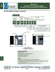
ØA<br />
Basic Part Number<br />
L2<br />
F - In-Line<br />
Receptacle with<br />
Cable Clamp and<br />
Bushing<br />
L3<br />
L1<br />
L4<br />
<strong>VG95234</strong> F<br />
In Line Receptacle with Cable Clamp,<br />
Bushing and Wire Sealing Grommet<br />
Contact<br />
Arrangement<br />
1 - Standard AWG Contacts<br />
(Omit for Metric)<br />
<strong>VG95234</strong> F 32-6 S 1 N<br />
1. 90° Plug connector without cable clamp and bushing.<br />
2. Standard crimp contact material consists of copper alloy with<br />
silver plating. Please see pages 16-17 for additional contact<br />
information.<br />
3. Insert arrangements IAW <strong>VG95234</strong>. Please see pages 10-15.<br />
P - Pin contacts<br />
S - Socket contacts<br />
APPLICATION NOTES<br />
© 2008 <strong>Glenair</strong>, <strong>Inc</strong>. U.S. CAGE Code 06324<br />
Printed in U.S.A.<br />
GLENAIR, INC. • 1211 AIR WAY • GLENDALE, CA 91201-2497 • 818-247-6000 • FAX 818-500-9912<br />
www.glenair.com 32<br />
E-Mail: sales@glenair.com<br />
D2<br />
L7<br />
L5<br />
Alternate Insert<br />
Positions<br />
N - X - Y<br />
4. Standard insert is synthetic rubber, oil and low temperature<br />
resistant (-55°C to +125°C) IAW MIL-R-3065.<br />
5. Stainless steel and marine bronze shells are available in Series<br />
ITS products. Please consult factory.<br />
6. All dimensions are metric unless otherwise noted.<br />
D1
<strong>VG95234</strong> F<br />
In Line Receptacle with Cable Clamp,<br />
Bushing and Wire Sealing Grommet<br />
Shell<br />
Size<br />
ØA<br />
+0<br />
-0.15<br />
D1<br />
Max<br />
D2<br />
Max<br />
L1<br />
Max<br />
DIMENSIONS<br />
L2<br />
±0.4<br />
-0<br />
© 2008 <strong>Glenair</strong>, <strong>Inc</strong>. U.S. CAGE Code 06324<br />
Printed in U.S.A.<br />
GLENAIR, INC. • 1211 AIR WAY • GLENDALE, CA 91201-2497 • 818-247-6000 • FAX 818-500-9912<br />
www.glenair.com 33<br />
E-Mail: sales@glenair.com<br />
L3<br />
±0.2<br />
L4<br />
Max<br />
L5<br />
±0.2<br />
L7<br />
Max<br />
Weight<br />
gr.<br />
Max<br />
10 SL 18.2 25.2 6.5 60 14.2 2.8 120 20.6 22.7 35<br />
14 S 24.6 29.8 9.0 62 14.2 3.2 120 25.4 27.5 50<br />
16 S 27.4 32.3 11.0 70 14.2 3.2 120 28.6 30.0 60<br />
16 27.4 32.3 11.0 70 19.0 3.2 125 28.6 30.0 65<br />
18 30.8 34.8 14.2 77 19.0 4.0 125 31.7 33.0 80<br />
20 34.2 37.8 15.8 77 19.0 4.0 125 34.9 37.5 95<br />
22 37.4 41.1 15.8 77 19.0 4.0 125 38.1 37.5 105<br />
24 40.9 44.6 21.4 85 20.6 4.0 125 41.3 43.3 140<br />
28 46.7 50.9 21.4 85 20.6 4.0 125 47.6 48.0 160<br />
32 53.4 57.1 26.7 85 22.2 4.0 125 54.0 55.0 205<br />
36 59.6 63.6 31.7 105 22.2 4.0 135 60.6 58.0 270<br />
MATERIALS<br />
SHELLS INSERTS (Temperature Range)<br />
Aluminum Alloy<br />
IAW QQ-A-591 Shells<br />
Stainless Steel<br />
Coupling Pins<br />
High Insulation Synthetic Rubber<br />
-55°C/+125°C<br />
CRIMP CONTACTS<br />
Stainless Steel Spring Copper Alloy with Silver Plating Over Nickel<br />
STANDARD FINISH<br />
(For QQ-A-591 Aluminum Shells)<br />
Requirements<br />
Cadmium with Olive<br />
Drab Passivation<br />
IAW QQ-P-416<br />
Thermal Shock -55°C + 125°C<br />
Salt Spray After<br />
Thermal Shock<br />
500 hour<br />
Electrical Conductivity Very Good<br />
Abrasion Resistance Very Good<br />
<strong>VG95234</strong><br />
<strong>Connectors</strong>
<strong>VG95234</strong><br />
<strong>Connectors</strong><br />
Basic Part Number<br />
G - Straight Plug<br />
with Heat Shrink<br />
Boot Adapter<br />
T - Add Grounding<br />
Fingers<br />
K<br />
3.5 ±0.2<br />
L1<br />
<strong>VG95234</strong> G and <strong>VG95234</strong> T<br />
Straight Plug with Heat Shrink Boot Adapter (G),<br />
Grounding Fingers (T), and Wire Sealing Grommet<br />
Contact<br />
Arrangement<br />
L5<br />
D6<br />
P - Pin contacts<br />
S - Socket contacts<br />
D5<br />
© 2008 <strong>Glenair</strong>, <strong>Inc</strong>. U.S. CAGE Code 06324<br />
Printed in U.S.A.<br />
GLENAIR, INC. • 1211 AIR WAY • GLENDALE, CA 91201-2497 • 818-247-6000 • FAX 818-500-9912<br />
www.glenair.com 34<br />
E-Mail: sales@glenair.com<br />
D4<br />
1 - Standard AWG Contacts<br />
(Omit for Metric)<br />
<strong>VG95234</strong> G 32-6 P 1 N<br />
1. Straight plug connector with wire sealing grommet and shrink<br />
boot adapter.<br />
2. Standard crimp contact material consists of copper alloy with<br />
silver plating. Please see pages 16-17 for additional contact<br />
information.<br />
3. Insert arrangements IAW <strong>VG95234</strong>. Please see pages 10-15.<br />
APPLICATION NOTES<br />
D3<br />
D1<br />
Alternate Insert<br />
Positions<br />
N - X - Y<br />
4. Standard insert is synthetic rubber, oil and low temperature<br />
resistant (-55°C to +125°C) IAW MIL-R-3065.<br />
5. Stainless steel and marine bronze shells are available in Series<br />
ITS products. Please consult factory.<br />
6. All dimensions are metric unless otherwise noted.
<strong>VG95234</strong> G and <strong>VG95234</strong> T<br />
Straight Plug with Heat Shrink Boot Adapter (G),<br />
Grounding Fingers (T), and Wire Sealing Grommet<br />
Shell<br />
Size<br />
D1<br />
Max<br />
D3<br />
±0.2<br />
D4<br />
±0.2<br />
DIMENSIONS<br />
D5<br />
Max<br />
D6<br />
Min<br />
© 2008 <strong>Glenair</strong>, <strong>Inc</strong>. U.S. CAGE Code 06324<br />
Printed in U.S.A.<br />
GLENAIR, INC. • 1211 AIR WAY • GLENDALE, CA 91201-2497 • 818-247-6000 • FAX 818-500-9912<br />
www.glenair.com 35<br />
E-Mail: sales@glenair.com<br />
K<br />
Key<br />
L1<br />
Max<br />
L5<br />
±0.5<br />
Weight<br />
gr.<br />
Max<br />
10 SL 22.8 17.0 15.5 13.3 7.7 20 50 11.7 26<br />
14 S 29.2 20.1 19.1 17.0 10.6 23 50 11.7 43<br />
16 S 32.0 23.5 23.9 21.9 13.5 26 50 11.7 53<br />
16 32.0 23.5 23.9 21.9 13.5 26 60 11.5 60<br />
18 36.5 26.5 23.9 21.9 14.6 28 60 11.5 67<br />
20 39.9 30.2 29.6 26.2 18.7 32 65 12.7 77<br />
22 43.1 33.6 29.6 26.2 20.8 36 65 12.7 82<br />
24 46.6 36.1 37.8 34.5 24.6 39 65 12.7 97<br />
28 53,4 41.4 37.8 34.5 27.0 46 65 12.7 122<br />
32 60.1 48.6 47.8 43.6 33.3 52 70 15.2 167<br />
36 66.3 54.8 47.8 43.6 38.5 58 80 15.2 182<br />
MATERIALS<br />
SHELLS INSERTS (Temperature Range)<br />
Aluminum Alloy<br />
IAW QQ-A-591 Shells<br />
Stainless Steel<br />
Coupling Pins<br />
High Insulation Synthetic Rubber<br />
-55°C/+125°C<br />
CRIMP CONTACTS<br />
Stainless Steel Spring Copper Alloy with Silver Plating Over Nickel<br />
STANDARD FINISH<br />
(For QQ-A-591 Aluminum Shells)<br />
Requirements<br />
Cadmium with Olive<br />
Drab Passivation<br />
IAW QQ-P-416<br />
Thermal Shock -55°C + 125°C<br />
Salt Spray After<br />
Thermal Shock<br />
500 hour<br />
Electrical Conductivity Very Good<br />
Abrasion Resistance Very Good<br />
<strong>VG95234</strong><br />
<strong>Connectors</strong>
<strong>VG95234</strong><br />
<strong>Connectors</strong><br />
Basic Part Number<br />
H - <strong>Inc</strong>ludes Wire<br />
Sealing Grommet;<br />
without Grounding<br />
Fingers<br />
L - With Grounding<br />
Fingers and Wire<br />
Sealing Grommet<br />
L1<br />
L2<br />
<strong>VG95234</strong> H and <strong>VG95234</strong> L<br />
Straight Plug with Conduit Adapter (H)<br />
and Grounding Fingers (L)<br />
Contact<br />
Arrangement<br />
P - Pin contacts<br />
S - Socket contacts<br />
D2<br />
© 2008 <strong>Glenair</strong>, <strong>Inc</strong>. U.S. CAGE Code 06324<br />
Printed in U.S.A.<br />
GLENAIR, INC. • 1211 AIR WAY • GLENDALE, CA 91201-2497 • 818-247-6000 • FAX 818-500-9912<br />
www.glenair.com 36<br />
E-Mail: sales@glenair.com<br />
D3<br />
1 - Standard AWG Contacts<br />
(Omit for Metric)<br />
<strong>VG95234</strong> H 32-6 P 1 N<br />
1. Straight Plug connector.<br />
2. Standard crimp contact material consists of copper alloy with<br />
silver plating. Please see pages 16-17 for additional contact<br />
information.<br />
3. Insert arrangements IAW <strong>VG95234</strong>. Please see pages 10-15.<br />
APPLICATION NOTES<br />
D1<br />
Alternate Insert<br />
Positions<br />
N - X - Y<br />
4. Standard insert is synthetic rubber, oil and low temperature<br />
resistant (-55°C to +125°C) IAW MIL-R-3065.<br />
5. Stainless steel and marine bronze shells are available in Series<br />
ITS products. Please consult factory.<br />
6. All dimensions are metric unless otherwise noted.
<strong>VG95234</strong> H and <strong>VG95234</strong> L<br />
Straight Plug with Conduit Adapter (H)<br />
and Grounding Fingers (L)<br />
Shell<br />
Size<br />
D1<br />
Max<br />
D2<br />
Min<br />
DIMENSIONS<br />
D3 L1<br />
Max<br />
© 2008 <strong>Glenair</strong>, <strong>Inc</strong>. U.S. CAGE Code 06324<br />
Printed in U.S.A.<br />
GLENAIR, INC. • 1211 AIR WAY • GLENDALE, CA 91201-2497 • 818-247-6000 • FAX 818-500-9912<br />
www.glenair.com 37<br />
E-Mail: sales@glenair.com<br />
L2<br />
Min<br />
Weight<br />
gr.<br />
Max<br />
10 SL 22.8 8.2 0.6250 - 24UNEF 50 9.5 21<br />
14 S 29.2 11.1 0.7500 - 20UNEF 50 9.5 33<br />
16 S 32.0 14.3 0.8750 - 20UNEF 50 9.5 42<br />
16 32.0 14.3 0.8750 - 20UNEF 60 9.5 51<br />
18 36.5 16.7 1.0000 - 20UNEF 60 9.5 59<br />
20 39.9 19.8 1.1875 - 18NEF 60 9.5 58<br />
22 43.1 19.8 1.1875 - 18NEF 60 9.5 62<br />
24 46.6 25.4 1.4375 - 18NEF 65 9.5 84<br />
28 53.4 27.0 1.4375 - 18NEF 65 9.5 100<br />
32 60.1 32.5 1.7500 - 18NS 65 11.0 116<br />
36 66.3 35.7 2.0000 - 18NS 80 11.8 142<br />
MATERIALS<br />
SHELLS INSERTS (Temperature Range)<br />
Aluminum Alloy<br />
IAW QQ-A-591 Shells<br />
Stainless Steel<br />
Coupling Pins<br />
High Insulation Synthetic Rubber<br />
-55°C/+125°C<br />
CRIMP CONTACTS<br />
Stainless Steel Spring Copper Alloy with Silver Plating Over Nickel<br />
STANDARD FINISH<br />
(For QQ-A-591 Aluminum Shells)<br />
Requirements<br />
Cadmium with Olive<br />
Drab Passivation<br />
IAW QQ-P-416<br />
Thermal Shock -55°C + 125°C<br />
Salt Spray After<br />
Thermal Shock<br />
500 hour<br />
Electrical Conductivity Very Good<br />
Abrasion Resistance Very Good<br />
<strong>VG95234</strong><br />
<strong>Connectors</strong>
<strong>VG95234</strong><br />
<strong>Connectors</strong><br />
ØA<br />
Basic Part Number<br />
Wall Mount<br />
Receptacle with<br />
Cable Clamp and<br />
Bushing and...<br />
J1 - Threaded<br />
Holes<br />
J2 - Thru-Holes<br />
L2 L3<br />
L1<br />
<strong>VG95234</strong> J1 and <strong>VG95234</strong> J2<br />
Wall Mount Receptacle<br />
with Cable Clamp, Bushing and Wire Sealing Grommet<br />
With Threaded (J1) and Thru-Holes (J2)<br />
L5<br />
Contact<br />
Arrangement<br />
1 - Standard AWG Contacts<br />
(Omit for Metric)<br />
<strong>VG95234</strong> J1 32-6 S 1 N<br />
1. Rear mount receptacle with wire sealing grommet, cable clamp<br />
and bushing.<br />
2. Standard crimp contact material consists of copper alloy with<br />
silver plating. Please see pages 16-17 for additional contact<br />
information.<br />
3. Insert arrangements IAW <strong>VG95234</strong>. Please see pages 10-15.<br />
P - Pin contacts<br />
S - Socket contacts<br />
APPLICATION NOTES<br />
<strong>VG95234</strong> J2<br />
© 2008 <strong>Glenair</strong>, <strong>Inc</strong>. U.S. CAGE Code 06324<br />
Printed in U.S.A.<br />
GLENAIR, INC. • 1211 AIR WAY • GLENDALE, CA 91201-2497 • 818-247-6000 • FAX 818-500-9912<br />
www.glenair.com 38<br />
E-Mail: sales@glenair.com<br />
D3<br />
D2 E<br />
L6<br />
D2<br />
Alternate Insert<br />
Positions<br />
N - X - Y<br />
4. Standard insert is synthetic rubber, oil and low temperature<br />
resistant (-55°C to +125°C) IAW MIL-R-3065.<br />
5. Stainless steel and marine bronze shells are available in Series<br />
ITS products. Please consult factory.<br />
6. All dimensions are metric unless otherwise noted.<br />
L4
<strong>VG95234</strong> J1 and <strong>VG95234</strong> J2<br />
Wall Mount Receptacle<br />
with Cable Clamp, Bushing and Wire Sealing Grommet<br />
With Threaded (J1) and Thru-Holes (J2)<br />
Shell<br />
Size<br />
ØA<br />
+0<br />
-0.15<br />
D2<br />
J1 J2<br />
H13<br />
D3<br />
Max<br />
DIMENSIONS<br />
E<br />
±0.1<br />
L1<br />
±0.3<br />
© 2008 <strong>Glenair</strong>, <strong>Inc</strong>. U.S. CAGE Code 06324<br />
Printed in U.S.A.<br />
GLENAIR, INC. • 1211 AIR WAY • GLENDALE, CA 91201-2497 • 818-247-6000 • FAX 818-500-9912<br />
www.glenair.com 39<br />
E-Mail: sales@glenair.com<br />
L2<br />
+0.4<br />
-0<br />
L3<br />
±0.2<br />
L4<br />
±0.3<br />
L5<br />
Max<br />
L6<br />
Max<br />
10 SL 18.2 M4 3.2 6.5 18.2 60 18.2 2.8 25.4 120 22.7 35<br />
14 S 24.6 M4 3.2 9.0 23.0 62 18.2 3.2 30.0 120 27.5 50<br />
16 S 27.4 M4 3.2 11.0 24.6 70 18.2 3.2 32.5 120 30.0 60<br />
16 27.4 M4 3.2 11.0 24.6 70 21.5 3.2 32.5 125 30.0 65<br />
18 30.8 M4 3.2 14.2 27.0 77 23.05 4.0 35.0 125 33.0 80<br />
20 34.2 M4 3.2 15.8 29.4 77 23.05 4.0 38.0 125 37.5 95<br />
22 37.4 M4 3.2 15.8 31.8 77 23.05 4.0 41.0 125 37.5 105<br />
24 40.9 M4 3.7 21.4 35.9 85 23.05 4.0 44.5 125 43.3 140<br />
28 46.7 M5 3.7 21.4 39.7 85 24.05 4.0 50.8 125 48.0 160<br />
32 53.4 M5 4.3 26.7 44.5 85 24.05 4.0 57.0 125 55.0 205<br />
36 59.6 M5 4.3 31.7 49.2 105 24.05 4.0 63.5 135 58.0 270<br />
MATERIALS<br />
SHELLS INSERTS (Temperature Range)<br />
Aluminum Alloy<br />
IAW QQ-A-591 Shells<br />
High Insulation Synthetic Rubber<br />
-55°C/+125°C<br />
CRIMP CONTACTS<br />
Copper Alloy with Silver Plating Over Nickel<br />
Weight<br />
gr.<br />
Max<br />
STANDARD FINISH<br />
(For QQ-A-591 Aluminum Shells)<br />
Requirements<br />
Cadmium with Olive<br />
Drab Passivation<br />
IAW QQ-P-416<br />
Thermal Shock -55°C + 125°C<br />
Salt Spray After<br />
Thermal Shock<br />
500 hour<br />
Electrical Conductivity Very Good<br />
Abrasion Resistance Very Good<br />
<strong>VG95234</strong><br />
<strong>Connectors</strong>
<strong>VG95234</strong><br />
<strong>Connectors</strong><br />
Basic Part Number<br />
K<br />
M - Straight<br />
Plug with EMI<br />
Backshell/Shrink<br />
Boot Adapter and<br />
Grounding Fingers<br />
3.5 ±0.2<br />
L1<br />
1<br />
L5<br />
L7<br />
<strong>VG95234</strong> M<br />
Straight Plug with EMI/RFI Backshell,<br />
Grounding Fingers, Wire Sealing Grommet<br />
and Heat Shrink Boot Lip<br />
Contact<br />
Arrangement<br />
L6<br />
P - Pin contacts<br />
S - Socket contacts<br />
D4 D6<br />
© 2008 <strong>Glenair</strong>, <strong>Inc</strong>. U.S. CAGE Code 06324<br />
Printed in U.S.A.<br />
GLENAIR, INC. • 1211 AIR WAY • GLENDALE, CA 91201-2497 • 818-247-6000 • FAX 818-500-9912<br />
www.glenair.com 40<br />
E-Mail: sales@glenair.com<br />
D5<br />
1 - Standard AWG Contacts<br />
(Omit for Metric)<br />
<strong>VG95234</strong> M 32-6 P 1 N<br />
1. Straight plug connector with EMI backshell and boot adapter.<br />
2. Standard crimp contact material consists of copper alloy with<br />
silver plating. Please see pages 16-17 for additional contact<br />
information.<br />
3. Insert arrangements IAW <strong>VG95234</strong>. Please see pages 10-15.<br />
APPLICATION NOTES<br />
D7<br />
D3<br />
Alternate Insert<br />
Positions<br />
N - X - Y<br />
4. Standard insert is synthetic rubber, oil and low temperature<br />
resistant (-55°C to +125°C) IAW MIL-R-3065.<br />
5. Stainless steel and marine bronze shells are available in Series<br />
ITS products. Please consult factory.<br />
6. All dimensions are metric unless otherwise noted.<br />
D1
<strong>VG95234</strong> M<br />
Straight Plug with Grounding Fingers,<br />
EMI/RFI Backshell, Wire Sealing Grommet<br />
and Heat Shrink Boot Lip<br />
Shell<br />
Size<br />
D1<br />
Max<br />
D3<br />
Max<br />
D4<br />
Min<br />
D5 D6<br />
Max<br />
DIMENSIONS<br />
D7<br />
±0.5<br />
© 2008 <strong>Glenair</strong>, <strong>Inc</strong>. U.S. CAGE Code 06324<br />
Printed in U.S.A.<br />
GLENAIR, INC. • 1211 AIR WAY • GLENDALE, CA 91201-2497 • 818-247-6000 • FAX 818-500-9912<br />
www.glenair.com 41<br />
E-Mail: sales@glenair.com<br />
K<br />
Key<br />
L1<br />
Max<br />
L5<br />
Min<br />
L6<br />
+1<br />
-0<br />
L7<br />
+1<br />
-0<br />
Weight<br />
gr.<br />
Max<br />
10 SL 22.8 22 8.6 M16+1 16.3 18.5 20 55 4.5 7 17 40<br />
14 S 29.2 25 10.6 M20+1 20.0 22.0 23 57 5.0 7 17 45<br />
16 S 32.0 28 13.5 M23+1 23.0 25.0 26 60 6.0 8 18 55<br />
16 32.0 28 13.5 M23+1 23.0 25.0 26 70 6.0 8 18 65<br />
18 36.5 31 14.6 M26+1 24.5 28.0 38 70 6.0 10 18 75<br />
20 39.9 35 18.5 M30+1 28.5 32.0 32 70 6.0 10 18 85<br />
22 43.1 38 20.8 M32+1 30.5 34.0 36 70 6.0 10 18 100<br />
24 46.6 41 24.6 M36+1 34.5 38.0 39 70 6.0 10 18 115<br />
28 53,4 48 27.0 M39+1 37.5 41.0 46 70 6.0 10 18 130<br />
32 60.1 54 33.3 M45+1 44.0 48.0 52 70 6.0 10 18 170<br />
36 66.3 61 38.5 M52+1 51.0 55.0 58 80 6.0 10 18 190<br />
MATERIALS<br />
SHELLS INSERTS (Temperature Range)<br />
Aluminum Alloy<br />
IAW QQ-A-591 Shells<br />
Stainless Steel<br />
Coupling Pins<br />
High Insulation Synthetic Rubber<br />
-55°C/+125°C<br />
CRIMP CONTACTS<br />
Stainless Steel Spring Copper Alloy with Silver Plating Over Nickel<br />
STANDARD FINISH<br />
(For QQ-A-591 Aluminum Shells)<br />
Requirements<br />
Cadmium with Olive<br />
Drab Passivation<br />
IAW QQ-P-416<br />
Thermal Shock -55°C + 125°C<br />
Salt Spray After<br />
Thermal Shock<br />
500 hour<br />
Electrical Conductivity Very Good<br />
Abrasion Resistance Very Good<br />
<strong>VG95234</strong><br />
<strong>Connectors</strong>
<strong>VG95234</strong><br />
<strong>Connectors</strong><br />
Basic Part Number<br />
ØA<br />
Rear Mount<br />
Receptacle with EMI<br />
Backshell/Shrink<br />
Boot Adapter and...<br />
N1 - Threaded Holes<br />
N2 - Thru-Holes<br />
L2<br />
K<br />
L3<br />
3.5 ±0.2<br />
L1<br />
1<br />
L5<br />
<strong>VG95234</strong> N1 and <strong>VG95234</strong> N2<br />
Wall Mount Receptacle<br />
with EMI/RFI Backshell and Heat Shrink Boot Lip,<br />
Sealing Grommet and Grounding Fingers<br />
Contact<br />
Arrangement<br />
L7<br />
L6<br />
D4 D6<br />
<strong>VG95234</strong> N2<br />
© 2008 <strong>Glenair</strong>, <strong>Inc</strong>. U.S. CAGE Code 06324<br />
Printed in U.S.A.<br />
GLENAIR, INC. • 1211 AIR WAY • GLENDALE, CA 91201-2497 • 818-247-6000 • FAX 818-500-9912<br />
www.glenair.com 42<br />
E-Mail: sales@glenair.com<br />
D5<br />
1 - Standard AWG Contacts<br />
(Omit for Metric)<br />
<strong>VG95234</strong> N1 32-6 S 1 N<br />
1. Rear wall mount receptacle with EMI backshell and shrink boot<br />
adapter.<br />
2. Standard crimp contact material consists of copper alloy with<br />
silver plating. Please see pages 16-17 for additional contact<br />
information.<br />
3. Insert arrangements IAW <strong>VG95234</strong>. Please see pages 10-15.<br />
P - Pin contacts<br />
S - Socket contacts<br />
APPLICATION NOTES<br />
D7<br />
D2<br />
D3<br />
D2<br />
Alternate Insert<br />
Positions<br />
N - X - Y<br />
4. Standard insert is synthetic rubber, oil and low temperature<br />
resistant (-55°C to +125°C) IAW MIL-R-3065.<br />
5. Stainless steel and marine bronze shells are available in Series<br />
ITS products. Please consult factory.<br />
6. All dimensions are metric unless otherwise noted.<br />
E<br />
L4
<strong>VG95234</strong> N1 and <strong>VG95234</strong> N2<br />
Wall Mount Receptacle<br />
with EMI/RFI Backshell and Heat Shrink Boot Lip,<br />
Sealing Grommet and Grounding Fingers<br />
Shell<br />
Size<br />
ØA<br />
+0<br />
-0.15<br />
D2<br />
N1 N2<br />
H13<br />
DIMENSIONS<br />
E<br />
±0.1<br />
© 2008 <strong>Glenair</strong>, <strong>Inc</strong>. U.S. CAGE Code 06324<br />
Printed in U.S.A.<br />
GLENAIR, INC. • 1211 AIR WAY • GLENDALE, CA 91201-2497 • 818-247-6000 • FAX 818-500-9912<br />
www.glenair.com 43<br />
E-Mail: sales@glenair.com<br />
L1<br />
Max<br />
L2<br />
+0.4<br />
-0<br />
L3<br />
±0.2<br />
L4<br />
±0.3<br />
Weight<br />
gr.<br />
Max<br />
10 SL 18.2 M4 3.2 18.2 55 18.2 2.8 25.4 45<br />
14 S 24.6 M4 3.2 23.0 58 18.2 3.2 30.0 55<br />
16 S 27.4 M4 3.2 24.6 70 18.2 3.2 32.5 65<br />
16 27.4 M4 3.2 24.6 70 21.5 3.2 32.5 75<br />
18 30.8 M4 3.2 27.0 70 23.05 4.0 35.0 85<br />
20 34.2 M4 3.2 29.4 70 23.05 4.0 38.0 95<br />
22 37.4 M4 3.2 31.8 70 23.05 4.0 41.0 105<br />
24 40.9 M4 3.7 35.9 70 23.05 4.0 44.5 120<br />
28 46.7 M5 3.7 39.7 70 24.05 4.0 50.8 150<br />
32 53.4 M5 4.3 44.5 75 24.05 4.0 57.0 190<br />
36 59.6 M5 4.3 49.2 85 24.05 4.0 63.5 220<br />
Please refer to <strong>VG95234</strong>M for dimensions D3, D4, D5, D6, D7, K, L5, L6 and L7.<br />
MATERIALS<br />
SHELLS INSERTS (Temperature Range)<br />
Aluminum Alloy<br />
IAW QQ-A-591 Shells<br />
High Insulation Synthetic Rubber<br />
-55°C/+125°C<br />
CRIMP CONTACTS<br />
Copper Alloy with Silver Plating Over Nickel<br />
STANDARD FINISH<br />
(For QQ-A-591 Aluminum Shells)<br />
Requirements<br />
Cadmium with Olive<br />
Drab Passivation<br />
IAW QQ-P-416<br />
Thermal Shock -55°C + 125°C<br />
Salt Spray After<br />
Thermal Shock<br />
500 hour<br />
Electrical Conductivity Very Good<br />
Abrasion Resistance Very Good<br />
<strong>VG95234</strong><br />
<strong>Connectors</strong>
<strong>VG95234</strong><br />
<strong>Connectors</strong><br />
Basic Part Number<br />
K<br />
R1 - Straight Plug<br />
with EMI Backshell/<br />
Shrink Boot Adapter<br />
and Grounding<br />
Fingers<br />
18 max<br />
L1<br />
<strong>VG95234</strong> R1<br />
Straight Plug with Grounding Fingers,<br />
EMI / RFI Backshell and Shrink Boot Adapter<br />
Contact<br />
Arrangement<br />
L5<br />
3.5 ±0.2<br />
D3<br />
D4 D6<br />
1 - Standard AWG Contacts<br />
(Omit for Metric)<br />
<strong>VG95234</strong> R1 32-6 P 1 N<br />
1. Straight plug connector with grounding fi nger EMI/RFI<br />
backshell and wire sealing grommet.<br />
2. Standard crimp contact material consists of copper alloy with<br />
silver plating. Please see pages 16-17 for additional contact<br />
information.<br />
3. Insert arrangements IAW <strong>VG95234</strong>. Please see pages 10-15.<br />
P - Pin contacts<br />
S - Socket contacts<br />
APPLICATION NOTES<br />
© 2008 <strong>Glenair</strong>, <strong>Inc</strong>. U.S. CAGE Code 06324<br />
Printed in U.S.A.<br />
GLENAIR, INC. • 1211 AIR WAY • GLENDALE, CA 91201-2497 • 818-247-6000 • FAX 818-500-9912<br />
www.glenair.com 44<br />
E-Mail: sales@glenair.com<br />
D5<br />
L6<br />
1 ±0.2<br />
D7<br />
Alternate Insert<br />
Positions<br />
N - X - Y<br />
4. Standard insert is synthetic rubber, oil and low temperature<br />
resistant (-55°C to +125°C) IAW MIL-R-3065.<br />
5. Stainless steel and marine bronze shells are available in Series<br />
ITS products. Please consult factory.<br />
6. All dimensions are metric unless otherwise noted.<br />
D1
<strong>VG95234</strong> R1<br />
Straight Plug with Grounding Fingers,<br />
EMI / RFI Backshell and Shrink Boot Adapter<br />
Shell<br />
Size Useable<br />
Inserts<br />
D1<br />
Max<br />
D3<br />
+0.2<br />
-0<br />
D4<br />
+0.4<br />
-0<br />
DIMENSIONS<br />
D5 D6<br />
±0.3<br />
© 2008 <strong>Glenair</strong>, <strong>Inc</strong>. U.S. CAGE Code 06324<br />
Printed in U.S.A.<br />
GLENAIR, INC. • 1211 AIR WAY • GLENDALE, CA 91201-2497 • 818-247-6000 • FAX 818-500-9912<br />
www.glenair.com 45<br />
E-Mail: sales@glenair.com<br />
D7<br />
±0.3<br />
K<br />
Key<br />
L1<br />
Max<br />
L5<br />
Max<br />
L6<br />
+0.2<br />
-0<br />
14 S 14S-6 29.2 10.0 14.0 M20x1 21.0 23.5 23 57 21 1.1 50<br />
16 S 16S-1 32.0 10.0 14.0 M20x1 21.0 23.5 26 57 21 1.1 60<br />
18 18-1 36.5 12.2 16.0 M22x1 23.0 25.5 38 66 21 1.1 80<br />
20 20-A48 39.9 13.4 18.0 M27x1 26.6 30.5 32 68 21 1.1 90<br />
28 28-21 53.4 19.0 26.5 M35x1 37.5 41.5 46 75 26 1.9 135<br />
32 32-A69 60.1 21.0 26.5 M35x1 37.5 41.5 52 79 26 1.9 175<br />
MATERIALS<br />
SHELLS INSERTS (Temperature Range)<br />
Aluminum Alloy<br />
IAW QQ-A-591 Shells<br />
Stainless Steel<br />
Coupling Pins<br />
High Insulation Synthetic Rubber<br />
-55°C/+125°C<br />
CRIMP CONTACTS<br />
Stainless Steel Spring Copper Alloy with Silver Plating Over Nickel<br />
Weight<br />
gr.<br />
Max<br />
STANDARD FINISH<br />
(For QQ-A-591 Aluminum Shells)<br />
Requirements<br />
Cadmium with Olive<br />
Drab Passivation<br />
IAW QQ-P-416<br />
Thermal Shock -55°C + 125°C<br />
Salt Spray After<br />
Thermal Shock<br />
500 hour<br />
Electrical Conductivity Very Good<br />
Abrasion Resistance Very Good<br />
<strong>VG95234</strong><br />
<strong>Connectors</strong>
<strong>VG95234</strong><br />
<strong>Connectors</strong><br />
Basic Part Number<br />
Rear Wall Mount<br />
Receptacle with EMI<br />
Backshell/Shrink<br />
Boot Adapter<br />
S1 - Threaded Holes<br />
S2 - Thru-Holes<br />
L2<br />
K<br />
L3<br />
<strong>VG95234</strong> S1 and <strong>VG95234</strong> S2<br />
Rear Wall Mount Receptacle with EMI / RFI Backshell,<br />
Dual-Lip Heat Shrink Boot Adapter<br />
ØA D5<br />
D4 D6<br />
D3<br />
18 max<br />
L1<br />
Contact<br />
Arrangement<br />
L5<br />
3.5 ±0.2<br />
1 - Standard AWG Contacts<br />
(Omit for Metric)<br />
<strong>VG95234</strong> S1 32-6 S 1 N<br />
1. Rear wall mount receptacle with EMI backshell.<br />
2. Standard crimp contact material consists of copper alloy with<br />
silver plating. Please see pages 16-17 for additional contact<br />
information.<br />
3. Insert arrangements IAW <strong>VG95234</strong>. Please see pages 10-15.<br />
P - Pin contacts<br />
S - Socket contacts<br />
APPLICATION NOTES<br />
<strong>VG95234</strong> S2<br />
© 2008 <strong>Glenair</strong>, <strong>Inc</strong>. U.S. CAGE Code 06324<br />
Printed in U.S.A.<br />
GLENAIR, INC. • 1211 AIR WAY • GLENDALE, CA 91201-2497 • 818-247-6000 • FAX 818-500-9912<br />
www.glenair.com 46<br />
E-Mail: sales@glenair.com<br />
L6<br />
1 ±0.2<br />
D7<br />
D2<br />
D2<br />
Alternate Insert<br />
Positions<br />
N - X - Y<br />
4. Standard insert is synthetic rubber, oil and low temperature<br />
resistant (-55°C to +125°C) IAW MIL-R-3065.<br />
5. Stainless steel and marine bronze shells are available in Series<br />
ITS products. Please consult factory.<br />
6. All dimensions are metric unless otherwise noted.<br />
E<br />
L4
<strong>VG95234</strong> S1 and <strong>VG95234</strong> S2<br />
Rear Wall Mount Receptacle with EMI / RFI Backshell,<br />
Dual-Lip Heat Shrink Boot Adapter<br />
DIMENSIONS<br />
Shell<br />
Size Useable<br />
Inserts<br />
ØA<br />
+0<br />
-0.15<br />
S1<br />
D2<br />
S2<br />
H13<br />
E<br />
±0.1<br />
L1<br />
Max<br />
L2<br />
+0.4<br />
-0<br />
L3<br />
±0.2<br />
L4<br />
±0.3<br />
Weight<br />
gr.<br />
Max<br />
14 S 14S-6 24.6 M4 3.2 23.0 61 18.2 3.2 30.0 60<br />
16 S 16S-1 27.4 M4 3.2 23.0 61 18.2 3.2 32.6 70<br />
18 18-1 30.8 M4 3.2 24.6 70 23.05 4.0 35.0 80<br />
20 20-A48 34.2 M4 3.2 24.6 72 23.05 4.0 38.0 90<br />
28 28-21 46.7 M4 3.7 27.0 78 24.05 4.0 50.8 155<br />
32 32-A69 53.4 M4 4.3 29.4 81 24.05 4.0 57.0 195<br />
Please refer to <strong>VG95234</strong>R1 for dimensions D3, D4, D5, D6, D7, K, l5, and l6.<br />
MATERIALS<br />
SHELLS INSERTS (Temperature Range)<br />
Aluminum Alloy<br />
High Insulation Synthetic Rubber<br />
IAW QQ-A-591 Shells<br />
-55°C/+125°C<br />
CRIMP CONTACTS<br />
Copper Alloy with Silver Plating Over Nickel<br />
STANDARD FINISH<br />
(For QQ-A-591 Aluminum Shells)<br />
Requirements<br />
Cadmium with Olive<br />
Drab Passivation<br />
IAW QQ-P-416<br />
Thermal Shock -55°C + 125°C<br />
Salt Spray After<br />
Thermal Shock<br />
500 hour<br />
Electrical Conductivity Very Good<br />
Abrasion Resistance Very Good<br />
© 2008 <strong>Glenair</strong>, <strong>Inc</strong>. U.S. CAGE Code 06324<br />
Printed in U.S.A.<br />
GLENAIR, INC. • 1211 AIR WAY • GLENDALE, CA 91201-2497 • 818-247-6000 • FAX 818-500-9912<br />
www.glenair.com 47<br />
E-Mail: sales@glenair.com<br />
<strong>VG95234</strong><br />
<strong>Connectors</strong>
<strong>VG95234</strong><br />
<strong>Connectors</strong><br />
Basic Part Number<br />
Rear Wall Mount<br />
Receptacle with Heat<br />
Shrink Boot Adapter<br />
U1 - Threaded Holes<br />
U2 - Thru-Holes<br />
L2<br />
ØA D6 D5 D4<br />
K<br />
L1<br />
L3<br />
3.5 ±0.2<br />
<strong>VG95234</strong> U1 and <strong>VG95234</strong> U2<br />
Rear Wall Mount Receptacle<br />
with Heat Shrink Boot Adapter and Sealing Grommet<br />
Contact<br />
Arrangement<br />
L5<br />
1 - Standard AWG Contacts<br />
(Omit for Metric)<br />
<strong>VG95234</strong> U1 32-6 S 1 N<br />
1. Rear wall mount receptacle with heat shrink boot adapter.<br />
2. Standard crimp contact material consists of copper alloy with<br />
silver plating. Please see pages 16-17 for additional contact<br />
information.<br />
3. Insert arrangements IAW <strong>VG95234</strong>. Please see pages 10-15.<br />
P - Pin contacts<br />
S - Socket contacts<br />
APPLICATION NOTES<br />
<strong>VG95234</strong> U2<br />
© 2008 <strong>Glenair</strong>, <strong>Inc</strong>. U.S. CAGE Code 06324<br />
Printed in U.S.A.<br />
GLENAIR, INC. • 1211 AIR WAY • GLENDALE, CA 91201-2497 • 818-247-6000 • FAX 818-500-9912<br />
www.glenair.com 48<br />
E-Mail: sales@glenair.com<br />
D2<br />
D3<br />
D2<br />
Alternate Insert<br />
Positions<br />
N - X - Y<br />
4. Standard insert is synthetic rubber, oil and low temperature<br />
resistant (-55°C to +125°C) IAW MIL-R-3065.<br />
5. Stainless steel and marine bronze shells are available in Series<br />
ITS products. Please consult factory.<br />
6. All dimensions are metric unless otherwise noted.<br />
E<br />
L4
<strong>VG95234</strong> U1 and <strong>VG95234</strong> U2<br />
Rear Wall Mount Receptacle<br />
with Heat Shrink Boot Adapter and Sealing Grommet<br />
Shell<br />
Size<br />
ØA<br />
+0<br />
-0.15<br />
D2<br />
B1 B2<br />
H13<br />
DIMENSIONS<br />
E<br />
±0.1<br />
MATERIALS<br />
SHELLS INSERTS (Temperature Range)<br />
Aluminum Alloy<br />
High Insulation Synthetic Rubber<br />
IAW QQ-A-591 Shells<br />
-55°C/+125°C<br />
CRIMP CONTACTS<br />
Copper Alloy with Silver Plating Over Nickel<br />
STANDARD FINISH<br />
(For QQ-A-591 Aluminum Shells)<br />
Requirements<br />
Cadmium with Olive<br />
Drab Passivation<br />
IAW QQ-P-416<br />
Thermal Shock -55°C + 125°C<br />
Salt Spray After<br />
Thermal Shock<br />
500 hour<br />
Electrical Conductivity Very Good<br />
Abrasion Resistance Very Good<br />
© 2008 <strong>Glenair</strong>, <strong>Inc</strong>. U.S. CAGE Code 06324<br />
Printed in U.S.A.<br />
GLENAIR, INC. • 1211 AIR WAY • GLENDALE, CA 91201-2497 • 818-247-6000 • FAX 818-500-9912<br />
www.glenair.com 49<br />
E-Mail: sales@glenair.com<br />
L1<br />
Max<br />
L2<br />
+0.4<br />
-0<br />
L3<br />
±0.2<br />
L4<br />
±0.3<br />
Weight<br />
gr.<br />
Max<br />
10 SL 18.2 M4 3.2 18.2 55 18.2 2.8 25.4 45<br />
14 S 24.6 M4 3.2 23.0 70 18.2 3.2 30.0 53<br />
16 S 27.4 M4 3.2 24.6 70 18.2 3.2 32.5 63<br />
16 27.4 M4 3.2 24.6 70 21.5 3.2 32.5 73<br />
18 30.8 M4 3.2 27.0 70 23.05 4.0 35.0 83<br />
20 34.2 M4 3.2 29.4 70 23.05 4.0 38.0 93<br />
22 37.4 M4 3.2 31.8 70 23.05 4.0 41.0 103<br />
24 40.9 M4 3.7 35.9 70 23.05 4.0 44.5 118<br />
28 46.7 M5 3.7 39.7 70 24.05 4.0 50.8 148<br />
32 53.4 M5 4.3 44.5 75 24.05 4.0 57.0 188<br />
36 59.6 M5 4.3 49.2 85 24.05 4.0 63.5 218<br />
Please refer to <strong>VG95234</strong>G for dimensions D3, D4, D5, D6, D7, K and L5.<br />
<strong>VG95234</strong><br />
<strong>Connectors</strong>
<strong>VG95234</strong><br />
Accessories<br />
1.<br />
2.<br />
D1<br />
L1<br />
D2<br />
Basic Part Number<br />
L2<br />
Metal protective cover for bayonet plug connectors with<br />
stainless steel chain.<br />
Standard materials confi guration consists of aluminum alloy<br />
with cadmium olive drab passivation IAW QQ-P-416.<br />
<strong>VG95234</strong> KB<br />
Plug Protective Cover<br />
With Stainless Steel Chain<br />
Connector<br />
Size<br />
APPLICATION NOTES<br />
3.<br />
Shell size<br />
<strong>VG95234</strong> KB - 14 S<br />
<strong>Bayonet</strong> Compatible<br />
Plug Cover with<br />
Stainless Steel Chain<br />
DIMENSIONS<br />
© 2008 <strong>Glenair</strong>, <strong>Inc</strong>. U.S. CAGE Code 06324<br />
Printed in U.S.A.<br />
GLENAIR, INC. • 1211 AIR WAY • GLENDALE, CA 91201-2497 • 818-247-6000 • FAX 818-500-9912<br />
www.glenair.com 50<br />
E-Mail: sales@glenair.com<br />
D1<br />
Max<br />
D2<br />
+0.6<br />
-0<br />
L1<br />
Min<br />
L2<br />
Max<br />
Weight<br />
gr.<br />
Max<br />
10 SL 21.0 4.3 90 29 19<br />
14 S 27.5 4.3 100 29 26<br />
16 S 30.0 4.3 100 29 28<br />
16 30.0 4.3 115 37 33<br />
18 33.5 4.3 115 37 36<br />
20 37.0 4.7 130 37 43<br />
22 40.0 4.7 130 37 47<br />
24 43.5 4.7 130 37 53<br />
28 49.5 4.7 190 37 63<br />
32 56.0 5.5 190 37 75<br />
36 62.5 5.5 190 37 88<br />
Other types of front and rear connector accessories are available.<br />
See our website and/or contact the factory for complete<br />
information.
D1<br />
1.<br />
2.<br />
L2L2<br />
<strong>VG95234</strong> KC<br />
Plug Protective Cover<br />
With Polyamide Black Rope<br />
L1 =<br />
Basic Part Number<br />
400 +20<br />
0.8<br />
5.5 ±0.3<br />
2 +0.2<br />
Metal protective cover for bayonet plug connectors with<br />
polyamide black rope.<br />
Standard materials confi guration consists of aluminum alloy<br />
with cadmium olive drab passivation IAW QQ-P-416.<br />
7 +3<br />
Rope Lanyard<br />
End Termination for<br />
Plug Cover<br />
© 2008 <strong>Glenair</strong>, <strong>Inc</strong>. U.S. CAGE Code 06324<br />
Printed in U.S.A.<br />
GLENAIR, INC. • 1211 AIR WAY • GLENDALE, CA 91201-2497 • 818-247-6000 • FAX 818-500-9912<br />
www.glenair.com 51<br />
E-Mail: sales@glenair.com<br />
Ø4<br />
3<br />
19<br />
4.1 +0.5<br />
7 +2<br />
APPLICATION NOTES<br />
3.<br />
Shell size<br />
<strong>VG95234</strong> KC - 14 S<br />
Connector<br />
Size<br />
DIMENSIONS<br />
D1<br />
Max<br />
L1<br />
Min<br />
L2<br />
Max<br />
Weight<br />
gr.<br />
Max<br />
10 SL 21.0 400 29 19<br />
14 S 27.5 400 29 26<br />
16 S 30.0 400 29 28<br />
16 30.0 400 37 33<br />
18 33.5 400 37 36<br />
20 37.0 400 37 43<br />
22 40.0 400 37 47<br />
24 43.5 400 37 53<br />
28 49.5 400 37 63<br />
32 56.0 400 37 75<br />
36 62.5 400 37 88<br />
Other types of front and rear connector accessories are available.<br />
See our website and/or contact the factory for complete<br />
information.<br />
<strong>VG95234</strong><br />
Accessories
<strong>VG95234</strong><br />
Accessories<br />
1.<br />
2.<br />
D1<br />
L1<br />
D2<br />
L2<br />
Metal protective cover for bayonet receptacle connectors with<br />
stainless steel chain.<br />
Standard materials confi guration consists of aluminum alloy<br />
with cadmium olive drab passivation IAW QQ-P-416.<br />
<strong>VG95234</strong> KR<br />
Receptacle Protective Cover<br />
With Stainless Steel Chain<br />
Connector<br />
Size<br />
APPLICATION NOTES<br />
3.<br />
DIMENSIONS<br />
© 2008 <strong>Glenair</strong>, <strong>Inc</strong>. U.S. CAGE Code 06324<br />
Printed in U.S.A.<br />
GLENAIR, INC. • 1211 AIR WAY • GLENDALE, CA 91201-2497 • 818-247-6000 • FAX 818-500-9912<br />
www.glenair.com 52<br />
E-Mail: sales@glenair.com<br />
D1<br />
Max<br />
Shell size<br />
<strong>VG95234</strong> KR - 14 S<br />
Basic Part Number<br />
<strong>Bayonet</strong> Compatible<br />
Receptacle Cover<br />
with Stainless Steel Chain<br />
D2<br />
+0.6<br />
-0<br />
L1<br />
Min<br />
L2<br />
Max<br />
Weight<br />
gr.<br />
Max<br />
10 SL 23.5 4.3 90 15.5 16<br />
14 S 30.5 4.3 90 15.5 18<br />
16 S 33.0 4.3 90 15.5 19<br />
16 33.0 4.3 100 21.2 23<br />
18 37.5 4.3 100 21.2 27<br />
20 41.0 4.7 115 21.2 30<br />
22 44.0 4.7 115 21.2 33<br />
24 47.5 4.7 115 21.2 37<br />
28 54.5 4.7 160 21.2 42<br />
32 61.0 5.5 160 21.2 48<br />
36 67.5 5.5 160 21.2 55<br />
Other types of front and rear connector accessories are available.<br />
See our website and/or contact the factory for complete<br />
information.
D1<br />
1.<br />
2.<br />
L2<br />
<strong>VG95234</strong> KA<br />
Receptacle Protective Cover<br />
With Polyamide Black Rope<br />
L2<br />
Metal protective cover for bayonet receptacle connectors with<br />
polyamide black rope.<br />
Standard materials confi guration consists of aluminum alloy<br />
with cadmium olive drab passivation IAW QQ-P-416.<br />
APPLICATION NOTES<br />
3.<br />
Shell size<br />
<strong>VG95234</strong> KA - 14 S<br />
Basic Part Number<br />
L1<br />
400 +20<br />
0.8<br />
5.5 ±0.3<br />
2 +0.2<br />
7 +3<br />
Rope Lanyard<br />
End Termination for<br />
Receptacle Cover<br />
Connector<br />
Size<br />
DIMENSIONS<br />
Other types of front and rear connector accessories are available.<br />
See our website and/or contact the factory for complete<br />
information.<br />
© 2008 <strong>Glenair</strong>, <strong>Inc</strong>. U.S. CAGE Code 06324<br />
Printed in U.S.A.<br />
GLENAIR, INC. • 1211 AIR WAY • GLENDALE, CA 91201-2497 • 818-247-6000 • FAX 818-500-9912<br />
www.glenair.com 53<br />
E-Mail: sales@glenair.com<br />
Ø4<br />
3<br />
19<br />
4.1 +0.5<br />
7 +2<br />
D1<br />
Max<br />
L1<br />
Min<br />
L2<br />
Max<br />
Weight<br />
gr.<br />
Max<br />
10 SL 23.5 400 15.5 16<br />
14 S 30.5 400 15.5 18<br />
16 S 33.0 400 15.5 19<br />
16 33.0 400 21.2 23<br />
18 37.5 400 21.2 27<br />
20 41.0 400 21.2 30<br />
22 44.0 400 21.2 33<br />
24 47.5 400 21.2 37<br />
28 54.5 400 21.2 42<br />
32 61.0 400 21.2 48<br />
36 67.5 400 21.2 55<br />
<strong>VG95234</strong><br />
<strong>Connectors</strong>
<strong>VG95234</strong><br />
Accessories<br />
1.<br />
2.<br />
D1<br />
Basic Part Number<br />
L3<br />
Dummy receptacle stowage fi tting protects the plug connector<br />
when not in use.<br />
Standard materials confi guration consists of aluminum alloy<br />
with cadmium olive drab passivation IAW QQ-P-416.<br />
<strong>VG95234</strong> B0D<br />
Dummy Plug Stowage Receptacle<br />
with Open Back for Front Panel Mount <strong>Connectors</strong><br />
D2<br />
APPLICATION NOTES<br />
3.<br />
Shell size<br />
<strong>VG95234</strong> B0D - 14 S<br />
DUMMY STOWAGE RECEPTACLE<br />
Dummy Plug Stowage<br />
Receptacle with Open back for Front<br />
Panel Mount <strong>Connectors</strong><br />
© 2008 <strong>Glenair</strong>, <strong>Inc</strong>. U.S. CAGE Code 06324<br />
Printed in U.S.A.<br />
GLENAIR, INC. • 1211 AIR WAY • GLENDALE, CA 91201-2497 • 818-247-6000 • FAX 818-500-9912<br />
www.glenair.com 54<br />
E-Mail: sales@glenair.com<br />
L2<br />
L1<br />
Other types of front and rear connector accessories are available.<br />
See our website and/or contact the factory for complete<br />
information.
<strong>VG95234</strong> B0D<br />
Dummy Plug Stowage Receptacle<br />
with Open Back for Front Panel Mount <strong>Connectors</strong><br />
Shell<br />
Size<br />
D1<br />
+0<br />
-0.15<br />
D2<br />
H13<br />
DIMENSIONS<br />
L1<br />
±0.3<br />
© 2008 <strong>Glenair</strong>, <strong>Inc</strong>. U.S. CAGE Code 06324<br />
Printed in U.S.A.<br />
GLENAIR, INC. • 1211 AIR WAY • GLENDALE, CA 91201-2497 • 818-247-6000 • FAX 818-500-9912<br />
www.glenair.com 55<br />
E-Mail: sales@glenair.com<br />
L2<br />
±0.1<br />
L3<br />
Max<br />
Weight<br />
gr.<br />
Max<br />
10 SL 18.2 3.2 25.4 18.2 17.5 14<br />
14 S 24.6 3.2 30.0 23.0 18.0 16<br />
16 S 27.4 3.2 32.5 24.6 18.0 18<br />
16 27.4 3.2 32.5 24.6 23.5 23<br />
18 30.8 3.2 35.0 27.0 23.5 26<br />
20 34.2 3.2 38.0 29.4 23.5 32<br />
22 37.4 3.2 41.0 31.8 23.5 36<br />
24 40.9 3.7 44.5 34.9 25.5 41<br />
28 46.7 3.7 50.8 39.7 25.5 52<br />
32 53.4 4.3 57.0 44.5 27.0 66<br />
36 59.6 4.3 63.5 49.2 27.0 80<br />
<strong>VG95234</strong><br />
Accessories
<strong>VG95234</strong><br />
Accessories<br />
1.<br />
2.<br />
D1<br />
Basic Part Number<br />
D3<br />
<strong>VG95234</strong> KK<br />
General Duty Class A Cable Clamp<br />
L3<br />
General duty Class A cable clamp suitable for jacketed or<br />
multipolar cable or wires protected by tubing.<br />
Standard materials confi guration consists of aluminum alloy<br />
with cadmium olive drab passivation IAW QQ-P-416.<br />
L2<br />
APPLICATION NOTES<br />
3.<br />
D2 L1<br />
Shell size<br />
<strong>VG95234</strong> KK - 6 A<br />
MIL-DTL-5015 Compatible<br />
General Duty Cable Clamp<br />
GENERAL DUTY CLASS A CABLE CLAMP<br />
Other types of front and rear connector accessories are available.<br />
See our website and/or contact the factory for complete<br />
information.<br />
© 2008 <strong>Glenair</strong>, <strong>Inc</strong>. U.S. CAGE Code 06324<br />
Printed in U.S.A.<br />
GLENAIR, INC. • 1211 AIR WAY • GLENDALE, CA 91201-2497 • 818-247-6000 • FAX 818-500-9912<br />
www.glenair.com 56<br />
E-Mail: sales@glenair.com
Part Number<br />
<strong>VG95234</strong> KK<br />
General Duty Class A Cable Clamp<br />
Connector<br />
Size<br />
Sleeve<br />
DIMENSIONS<br />
D1<br />
±0.8<br />
<strong>VG95234</strong> KK - 4A 10SL <strong>VG95234</strong> KT 10SL 20.63 0.6250-24UNEF 8.0 22.23 20.63 10.3 15<br />
<strong>VG95234</strong> KK - 6A 14S <strong>VG95234</strong> KT 14S 24.61 0.7500-20UNEF 11.2 26.98 22.23 10.3 20<br />
<strong>VG95234</strong> KK - 8A 16 - 16S IT 3420 - 8 27.79 0.8750-20UNEF 14.3 29.36 23.83 10.3 25<br />
<strong>VG95234</strong> KK - 10A 18 IT 3420 - 10 30.18 1.0000-20UNEF 15.9 31.75 23.83 10.3 25<br />
<strong>VG95234</strong> KK - 12A 20 - 22 IT 3420 - 12 34.93 1.1875-18NEF 19.1 37.31 23.83 10.3 35<br />
<strong>VG95234</strong> KK- 16A 24 - 28 <strong>VG95234</strong> KT 24 42.06 1.4375-18NEF 23.9 42.88 26.19 10.3 45<br />
<strong>VG95234</strong> KK - 20A 32 <strong>VG95234</strong> KT 34 51.59 1.7500 - 18UNS 31.8 51.59.5 27.79 11.9 55<br />
<strong>VG95234</strong> KK - 24A 36 IT 3420 - 24 56.36 2.000 - 18UNS 35.0 57.94 29.36 13.5 75<br />
© 2008 <strong>Glenair</strong>, <strong>Inc</strong>. U.S. CAGE Code 06324<br />
Printed in U.S.A.<br />
GLENAIR, INC. • 1211 AIR WAY • GLENDALE, CA 91201-2497 • 818-247-6000 • FAX 818-500-9912<br />
www.glenair.com 57<br />
E-Mail: sales@glenair.com<br />
D2<br />
D3<br />
Max<br />
L1<br />
±0.8<br />
L2<br />
±0.8<br />
L3<br />
Weight<br />
gr.<br />
Max<br />
<strong>VG95234</strong><br />
Accessories
<strong>VG95234</strong><br />
Accessories<br />
1.<br />
D2<br />
Basic Part Number<br />
Neoprene bushing for protection and reduction, used with<br />
Class A cable clamps.<br />
<strong>VG95234</strong> KT<br />
Neoprene Bushing for Cable<br />
Used with General Duty Class A Cable Clamps<br />
NEOPRENE BUSHING<br />
© 2008 <strong>Glenair</strong>, <strong>Inc</strong>. U.S. CAGE Code 06324<br />
Printed in U.S.A.<br />
GLENAIR, INC. • 1211 AIR WAY • GLENDALE, CA 91201-2497 • 818-247-6000 • FAX 818-500-9912<br />
www.glenair.com 58<br />
E-Mail: sales@glenair.com<br />
D1<br />
L D3<br />
APPLICATION NOTES<br />
2.<br />
Shell size<br />
<strong>VG95234</strong> KK - 6 A<br />
MIL-DTL-5015 Compatible<br />
General Duty Cable Clamp<br />
Other types of front and rear connector accessories are available.<br />
See our website and/or contact the factory for complete<br />
information.
<strong>VG95234</strong> KT<br />
Neoprene Bushing for Cable<br />
Used with General Duty Class A Cable Clamps<br />
Connector<br />
Size<br />
Part Number<br />
DIMENSIONS<br />
D1<br />
±0.1<br />
© 2008 <strong>Glenair</strong>, <strong>Inc</strong>. U.S. CAGE Code 06324<br />
Printed in U.S.A.<br />
GLENAIR, INC. • 1211 AIR WAY • GLENDALE, CA 91201-2497 • 818-247-6000 • FAX 818-500-9912<br />
www.glenair.com 59<br />
E-Mail: sales@glenair.com<br />
D2<br />
±0.1<br />
D3<br />
±0.1<br />
L<br />
±0.1<br />
Weight<br />
gr.<br />
Max<br />
10SL 10-234 KT 10SL 8.00 6.60 10.0 69.8 3<br />
14S 10-234 KT 14S 10.90 9.10 12.7 66.8 5<br />
16 - 16S IT 3420 - 8 14.02 11.09 18.8 63.5 6<br />
18 IT 3420 - 10 15.62 14.27 22.6 60.3 4<br />
20 - 22 IT 3420 -12 18.79 15.87 27.5 57.1 7<br />
24 - 28 10-234 KT 24 23.60 21.50 33.3 53.9 13<br />
32 10-234 KT 32 31.49 26.80 40.4 50.8 26<br />
36 IT 3420 - 24 34.67 31.75 46.9 47.6 30<br />
<strong>VG95234</strong><br />
Accessories
<strong>VG95234</strong><br />
Accessories<br />
1.<br />
S<br />
D1<br />
D2<br />
Basic Part Number<br />
Conductive and non-conductive gaskets for front-mount square<br />
fl ange receptacles.<br />
E<br />
L<br />
<strong>VG95234</strong> DA1 and <strong>VG95234</strong> DA2<br />
Front Panel Mount Receptacle Gasket<br />
Non-Conductive (DA ... 1) and Conductive (DA ... 2)<br />
APPLICATION NOTES<br />
2.<br />
Shell size<br />
<strong>VG95234</strong> DA 18 - 1<br />
Mounting Gaskets<br />
for Front-Mounted Square Flange<br />
Receptacles<br />
DA ... - 1 = Non-Conductive<br />
DA ... - 2 = Conductive<br />
FRONT PANEL MOUNT RECEPTACLE GASKET<br />
DA1 Non-Conductive DA2 Conductive<br />
Other types of front and rear connector accessories are available.<br />
See our website and/or contact the factory for complete<br />
information.<br />
© 2008 <strong>Glenair</strong>, <strong>Inc</strong>. U.S. CAGE Code 06324<br />
Printed in U.S.A.<br />
GLENAIR, INC. • 1211 AIR WAY • GLENDALE, CA 91201-2497 • 818-247-6000 • FAX 818-500-9912<br />
www.glenair.com 60<br />
E-Mail: sales@glenair.com<br />
S<br />
D1<br />
D2<br />
E<br />
L
<strong>VG95234</strong> DA1 and <strong>VG95234</strong> DA2<br />
Front Panel Mount Receptacle Gasket<br />
Non-Conductive (DA ... 1) and Conductive (DA ... 2)<br />
Part Number<br />
Shell<br />
Size<br />
DIMENSIONS<br />
D1<br />
+1<br />
-0<br />
© 2008 <strong>Glenair</strong>, <strong>Inc</strong>. U.S. CAGE Code 06324<br />
Printed in U.S.A.<br />
GLENAIR, INC. • 1211 AIR WAY • GLENDALE, CA 91201-2497 • 818-247-6000 • FAX 818-500-9912<br />
www.glenair.com 61<br />
E-Mail: sales@glenair.com<br />
D2<br />
+0.5<br />
-0<br />
E<br />
±0.2<br />
L<br />
±0.5<br />
S<br />
1<br />
±0.4<br />
2<br />
±0.2<br />
<strong>VG95234</strong> DA 10SL 10SL 15.7 4.2 18.2 24.4 1.0 0.5 2<br />
<strong>VG95234</strong> DA 14S 14S 22.1 4.2 23.0 30.0 1.0 0.5 2<br />
<strong>VG95234</strong> DA 16 16S - 16 25.3 4.2 24.6 32.5 1.0 0.5 2<br />
<strong>VG95234</strong> DA 18 18 28.4 4.2 27.0 35.0 1.0 0.5 2<br />
<strong>VG95234</strong> DA 20 20 31.6 4.2 29.4 38.0 1,0 0.5 2<br />
<strong>VG95234</strong> DA 22 22 34.8 4.2 31.8 41.0 1.0 0.5 2<br />
<strong>VG95234</strong> DA 28 28 44.3 5.1 39.7 50.8 1.0 0.5 2<br />
<strong>VG95234</strong> DA 32 32 50.7 5.1 44.5 57.0 1.0 0.5 2<br />
<strong>VG95234</strong> DA 36 36 57.0 5.1 49.2 63.5 1.0 0.5 2<br />
Weight<br />
gr.<br />
Max<br />
<strong>VG95234</strong><br />
Accessories
<strong>VG95234</strong><br />
Accessories<br />
1.<br />
S<br />
D1<br />
D2<br />
Basic Part Number<br />
Conductive and non-conductive gaskets for rear panel-mount<br />
square fl ange receptacles.<br />
E<br />
L<br />
<strong>VG95234</strong> DH1 and <strong>VG95234</strong> DH2<br />
Rear Panel Mount Receptacle Gasket<br />
Non-Conductive (DH ... 1) and Conductive (DH ... 2)<br />
APPLICATION NOTES<br />
2.<br />
Shell size<br />
<strong>VG95234</strong> DH 18 - 1<br />
Mounting Gaskets<br />
for Front-Mounted Square Flange<br />
Receptacles<br />
DH ... - 1 = Non-Conductive<br />
DH ... - 2 = Conductive<br />
REAR PANEL MOUNT RECEPTACLE GASKET<br />
DH1 Non-Conductive DH2 Conductive<br />
Other types of front and rear connector accessories are available.<br />
See our website and/or contact the factory for complete<br />
information.<br />
© 2008 <strong>Glenair</strong>, <strong>Inc</strong>. U.S. CAGE Code 06324<br />
Printed in U.S.A.<br />
GLENAIR, INC. • 1211 AIR WAY • GLENDALE, CA 91201-2497 • 818-247-6000 • FAX 818-500-9912<br />
www.glenair.com 62<br />
E-Mail: sales@glenair.com<br />
S<br />
D1<br />
D2<br />
E<br />
L
<strong>VG95234</strong> DH1 and <strong>VG95234</strong> DH2<br />
Rear Panel Mount Receptacle Gasket<br />
Non-Conductive (DH ... 1) and Conductive (DH ... 2)<br />
Part Number<br />
Shell<br />
Size<br />
DIMENSIONS<br />
D1<br />
+0.3<br />
-0<br />
© 2008 <strong>Glenair</strong>, <strong>Inc</strong>. U.S. CAGE Code 06324<br />
Printed in U.S.A.<br />
D2<br />
+0.5<br />
-0<br />
GLENAIR, INC. • 1211 AIR WAY • GLENDALE, CA 91201-2497 • 818-247-6000 • FAX 818-500-9912<br />
www.glenair.com 63<br />
E-Mail: sales@glenair.com<br />
E<br />
±0.2<br />
L<br />
±0.5<br />
1<br />
±0.4<br />
S<br />
2<br />
±0.2<br />
<strong>VG95234</strong> DH 10SL 10SL 18.2 4.2 18.2 24.4 1.0 0.5 2<br />
<strong>VG95234</strong> DH 14S 14S 24.6 4.2 23.0 30.0 1.0 0.5 2<br />
<strong>VG95234</strong> DH 16 16S - 16 27.4 4.2 24.6 32.5 1.0 0.5 2<br />
<strong>VG95234</strong> DH 18 18 30.8 4.2 27.0 35.0 1.0 0.5 2<br />
<strong>VG95234</strong> DH 20 20 34.2 4.2 29.4 38.0 1,0 0.5 2<br />
<strong>VG95234</strong> DH 22 22 37.4 4.2 31.8 41.0 1.0 0.5 2<br />
<strong>VG95234</strong> DH 24 24 40.9 4.2 34.9 44.5 1.0 0.5 2<br />
<strong>VG95234</strong> DH 28 28 46.7 5.1 39.7 50.8 1.0 0.5 2<br />
<strong>VG95234</strong> DH 32 32 53.4 5.1 44.5 57.0 1.0 0.5 2<br />
<strong>VG95234</strong> DH 36 36 59.6 5.1 49.2 63.5 1.0 0.5 2<br />
g<br />
Max<br />
<strong>VG95234</strong><br />
Accessories
Index<br />
Product Line Overview..........................................1<br />
Applications....................................................2<br />
Available Components..........................................3<br />
Crimp Contact Connector Cross Reference.........4<br />
Crimp Contact Connector Technical Data.............5<br />
Master How to Order.............................................6<br />
Commercial Equivalent Product Line....................7<br />
Pin Contact Arrangements....................................8<br />
Contact Arrangements and Alternate Keyway<br />
Positions......................................................9<br />
Contact Arrangements Front View......................10<br />
Pin Contacts........................................................14<br />
Socket Contacts.................................................15<br />
<strong>VG95234</strong> A Front Panel Wall Mount<br />
Receptacle.................................................16<br />
<strong>VG95234</strong> B1 and B2 Rear Panel<br />
Wall Mount Receptacle................................18<br />
<strong>VG95234</strong> C1 and C2 Bulkhead<br />
Feed-Thru Receptacle.................................20<br />
<strong>VG95234</strong> D Straight Plug with Cable Clamp,<br />
Bushing and Wire Sealing Grommet...........22<br />
<strong>VG95234</strong> E 90° Plug with Cable Clamp,<br />
Bushing and Wire Sealing Grommet...........24<br />
<strong>VG95234</strong> E1 and K 90° Plug with Conduit<br />
Adapter (E1) and Grounding Fingers (K).......26<br />
<strong>VG95234</strong> F In-Line Receptacle with Cable Clamp,<br />
Bushing and Wire Sealing Grommet............28<br />
VG94234 G and T Straight Plug with Heat Shrink<br />
Boot Adapter (G), Grounding Fingers (T), and<br />
Wire Sealing Grommet.................................30<br />
<strong>VG95234</strong> H and <strong>VG95234</strong> L<br />
Straight Plug with Conduit Adapter (H)<br />
and Grounding Fingers (L)...........................32<br />
<strong>VG95234</strong> J1 and J2 Wall Mount Receptacle with<br />
Cable Clamp, Bushing & Wire Sealing Grommet,<br />
Threaded (J1) and Thru-Holes (J2).............34<br />
<strong>VG95234</strong> <strong>Bayonet</strong>-<strong>Lock</strong> <strong>Connectors</strong><br />
Index<br />
<strong>VG95234</strong> M Straight Plug with EMI/RFI Backshell,<br />
Grounding Fingers, Wire Sealing Grommet<br />
and Heat Shrink Boot Lip.............................36<br />
<strong>VG95234</strong> N1 and N2 Wall Mount Receptacle with<br />
EMI/RFI Backshell and Heat Shrink Boot Lip,<br />
Sealing Grommet & Grounding Fingers..........38<br />
<strong>VG95234</strong> R1 Straight Plug w/ EMI/RFI Backshell,<br />
Grounding Fingers, Wire Sealing Grommet<br />
and Dual-Lip Shrink Boot Adapter................40<br />
<strong>VG95234</strong> S1 and S2 Wall Mount Receptacle with<br />
EMI/RFI Backshell, Dual-Lip Heat Shrink<br />
Boot Adapter, Sealing Grommet and<br />
Grounding Fingers.......................................42<br />
<strong>VG95234</strong> U1 and U2 Wall Mount Receptacle<br />
with Heat Shrink Boot Adapter and<br />
Sealing Grommet.........................................44<br />
<strong>VG95234</strong> KB Protective Plug Cover with<br />
Stainless Steel Chain...................................46<br />
<strong>VG95234</strong> KC Rope Lanyard End Termination<br />
for KB PLug Cover.......................................47<br />
<strong>VG95234</strong> KR Protective Receptacle Cover<br />
with Stainless Steel Chain...........................48<br />
<strong>VG95234</strong> KA Rope Lanyard End Termination<br />
for KR Receptacle Cover.............................49<br />
<strong>VG95234</strong> B0D Dummy Plug Stowage<br />
Receptacle with Open Back for Front Panel<br />
Mount <strong>Connectors</strong>........................................50<br />
<strong>VG95234</strong> KK General Duty<br />
Class A Cable Clamp...................................52<br />
<strong>VG95234</strong> KT Neoprene Bushing for Cable used<br />
with General Duty Class A Cable Clamps.......54<br />
<strong>VG95234</strong> DA1 and DA2Front Panel Mount<br />
Receptacle Gasket, Non-Conductive (DA1),<br />
Conductive (DA2)........................................56<br />
<strong>VG95234</strong> DH1 and DH2 Rear Panel Mount<br />
Receptacle Gasket, Non-Conductive (DH1),<br />
Conductive (DH2)........................................58<br />
© 2008 <strong>Glenair</strong>, <strong>Inc</strong>. U.S. CAGE Code 06324<br />
Printed in U.S.A.<br />
GLENAIR, INC. • 1211 AIR WAY • GLENDALE, CA 91201-2497 • 818-247-6000 • FAX 818-500-9912<br />
www.glenair.com 64<br />
E-Mail: sales@glenair.com
More Options Than Ever Before!<br />
<strong>Glenair</strong> Commercial Series ITS<br />
Reverse <strong>Bayonet</strong> <strong>Connectors</strong><br />
Ruggedized Environmental<br />
Power and Signal <strong>Connectors</strong><br />
Over 200 MIL-C-5015 Insert Arrangements • Improved<br />
Reverse <strong>Bayonet</strong> Coupling • Now VG 95234 Qualifi ed!<br />
United States United Kingdom Germany France Nordic Italy Spain Japan<br />
EU Sales: <strong>Glenair</strong> <strong>Connectors</strong> Italia, S.r.L. Tel: +39-02-91082121 Email: sales-italia@glenair.com<br />
North American Sales: <strong>Glenair</strong> Connecticut, Tel: 203-741-1115 Email: sales@glenair.com<br />
Factory Support: Commital S.p.a. (Italy) Tel: +39-51-7821811 Email: commital@commital.com<br />
www.glenair.com<br />
A World of Interconnect Solutions
A World of<br />
Interconnect<br />
Solutions<br />
<strong>Glenair</strong>, <strong>Inc</strong>.<br />
1211 Air Way • Glendale, California • 91201-2497<br />
Telephone: 818-247-6000 • Fax: 818-500-9912 • sales@glenair.com<br />
www.glenair.com<br />
<strong>Glenair</strong> Industrial Power and<br />
Signal Connector Group<br />
25 Village Lane<br />
Wallingford, CT<br />
06492<br />
<strong>Glenair</strong> Microway Systems<br />
7000 North Lawndale Avenue<br />
Lincolnwood, IL<br />
60712<br />
<strong>Glenair</strong> Electric GmbH<br />
Siemensstrasse 9<br />
D-61449 Steinbach<br />
Germany<br />
<strong>Glenair</strong> Italia S.R.L.<br />
Via Santi, 1<br />
20037 Paderno Dugnano<br />
Milano, Italy<br />
Telephone:<br />
203-741-1115<br />
Facsimile:<br />
203-741-0053<br />
sales@glenair.com<br />
Telephone:<br />
847-679-8833<br />
Facsimile:<br />
847-679-8849<br />
Telephone:<br />
49-6171-5905-0<br />
Facsimile:<br />
49-6171-5905-90<br />
germany@glenair.com<br />
Telephone:<br />
39-02-91082121<br />
Facsimile:<br />
39-02-99043565<br />
sales-italia@glenair.it<br />
© 2008 <strong>Glenair</strong>, <strong>Inc</strong>. Printed in U.S.A.<br />
<strong>Glenair</strong> UK Ltd<br />
40 Lower Oakham Way<br />
Oakham Business Park<br />
P.O. Box 37, Mansfi eld<br />
Notts, NG18 5BY England<br />
<strong>Glenair</strong> Nordic AB<br />
Gustav III : S Boulevard 46<br />
S - 169 27 Solna<br />
Sweden<br />
<strong>Glenair</strong> Iberica<br />
C/ La Vega, 16<br />
45612 Velada<br />
Spain<br />
<strong>Glenair</strong> France SARL<br />
7, Avenue Parmentier<br />
Immeuble Central Parc #2<br />
31200 Toulouse<br />
France<br />
Telephone:<br />
44-1623-638100<br />
Facsimile:<br />
44-1623-638111<br />
sales@glenair.co.uk<br />
Telephone:<br />
46-8-50550000<br />
Facsimile:<br />
46-8-50550001<br />
sales@glenair.se<br />
Telephone:<br />
34-925-89-29-88<br />
Facsimile:<br />
34-925-89-29-87<br />
sales@glenair.es<br />
Telephone:<br />
33-5-34-40-97-40<br />
Facsimile:<br />
33-5-61-47-86-10<br />
sales@glenair.fr