CANopen Programmer's Manual - Maccon.de
CANopen Programmer's Manual - Maccon.de
CANopen Programmer's Manual - Maccon.de

You also want an ePaper? Increase the reach of your titles
YUMPU automatically turns print PDFs into web optimized ePapers that Google loves.
4: Control Loop Configuration <strong>CANopen</strong> Programmer’s <strong>Manual</strong><br />
The Velocity Loop<br />
Overview of the Velocity Loop<br />
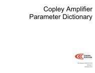
As shown below, the velocity loop limiting stage accepts a velocity command, applies limits, and<br />
passes a limited velocity command to the input filter. The filter then passes a velocity command to<br />
the summing junction. The summing junction subtracts the actual velocity, represented by the<br />
feedback signal, and produces an error signal. (The velocity loop feedback signal is always from<br />
the motor feedback <strong>de</strong>vice even when an additional enco<strong>de</strong>r is attached to the load.) The error<br />
signal is then processed using the integral and proportional gains to produce a current command.<br />
Programmable digital filters are provi<strong>de</strong>d on both the input and output command signals.<br />
Velocity<br />
Command<br />
Velocity Limiter<br />
Filter<br />
Limited<br />
Velocity<br />
Velocity Loop<br />
Velocity Integral Gain (Vi)<br />
Velocity Proportional Gain (Vp)<br />
Limits:<br />
Velocity<br />
Acceleration*<br />
Feedback (Derived Velocity)<br />
Deceleration*<br />
Emergency Stop Deceleration*<br />
*Not used w hen velocity loop is controlled by position loop. See "Velocity Loop Limits" for <strong>de</strong>tails.<br />
+<br />
-<br />
Current<br />
Command<br />
Velocity Loop Limits<br />
The velocity loop starts with a command limiter. This is useful because the position loop may<br />
produce large spikes in its output velocity command value that are beyond the safe operating<br />
range of the motor. During normal operation, with the velocity loop driven by the position loop, the<br />
limiter requires and accepts only a maximum velocity value.<br />
Optionally, the velocity loop can be driven by an alternate source of control (such as such as the<br />
<strong>de</strong>vice’s serial port, digital I/O channels, analog reference, or internal generator), without input<br />
from the position loop. (See Alternative Control Sources Overview, p. 225.) In these cases, the<br />
velocity loop limiter also requires and accepts maximum acceleration and <strong>de</strong>celeration values.<br />
Velocity limiter parameters are accessed through the following objects:<br />
Limiter Object Name/ID Page #<br />
Velocity Loop – Maximum Velocity / 0x2103 (used in all control mo<strong>de</strong>s) 145<br />
*Velocity Loop Maximum Acceleration / 0x2100 (used only without position loop) 144<br />
*Velocity Loop Maximum Deceleration / 0x2101 (used only without position loop) 145<br />
Velocity Loop Emergency Stop Deceleration / 0x2102 (used only without position loop) 145<br />
*Not used when velocity loop is controlled by position loop.<br />
Velocity Loop Input<br />
The output of the velocity loop limiter is the input of the velocity loop. It is accessed through the<br />
object Limited Velocity (in<strong>de</strong>x 0x2230, p. 146).<br />
Velocity Loop Gains<br />
The velocity loop uses the following gains. See Error! Reference source not found. (in<strong>de</strong>x<br />
0x2381, p. 146).<br />
Gain Description<br />
Vp - Velocity loop<br />
proportional<br />
The velocity error (the difference between the actual and the limited comman<strong>de</strong>d velocity) is<br />
multiplied by this gain. The primary effect of this gain is to increase bandwidth (or <strong>de</strong>crease the<br />
step-response time) as the gain is increased.<br />
132 Copley Controls<br />
+<br />
+<br />
Filter