CANopen Programmer's Manual - Maccon.de
CANopen Programmer's Manual - Maccon.de
CANopen Programmer's Manual - Maccon.de

You also want an ePaper? Increase the reach of your titles
YUMPU automatically turns print PDFs into web optimized ePapers that Google loves.
3: Device Control, Configuration, and Status <strong>CANopen</strong> Programmer’s <strong>Manual</strong><br />
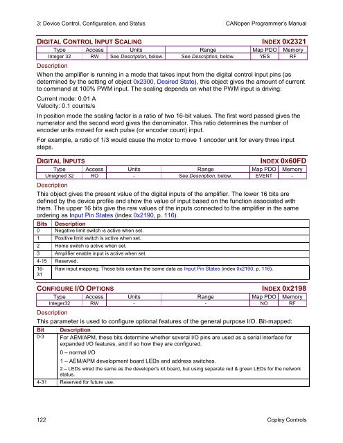
DIGITAL CONTROL INPUT SCALING INDEX 0X2321<br />
Type Access Units Range Map PDO Memory<br />
Integer 32 RW See Description, below. See Description, below. YES RF<br />
Description<br />
When the amplifier is running in a mo<strong>de</strong> that takes input from the digital control input pins (as<br />
<strong>de</strong>termined by the setting of object 0x2300, Desired State), this object gives the amount of current<br />
to command at 100% PWM input. The scaling <strong>de</strong>pends on what the PWM input is driving:<br />
Current mo<strong>de</strong>: 0.01 A<br />
Velocity: 0.1 counts/s<br />
In position mo<strong>de</strong> the scaling factor is a ratio of two 16-bit values. The first word passed gives the<br />
numerator and the second word gives the <strong>de</strong>nominator. This ratio <strong>de</strong>termines the number of<br />
enco<strong>de</strong>r units moved for each pulse (or enco<strong>de</strong>r count) input.<br />
For example, a ratio of 1/3 would cause the motor to move 1 enco<strong>de</strong>r unit for every three input<br />
steps.<br />
DIGITAL INPUTS INDEX 0X60FD<br />
Type Access Units Range Map PDO Memory<br />
Unsigned 32 RO - See Description, below. EVENT -<br />
Description<br />
This object gives the present value of the digital inputs of the amplifier. The lower 16 bits are<br />
<strong>de</strong>fined by the <strong>de</strong>vice profile and show the value of input based on the function associated with<br />
them. The upper 16 bits give the raw values of the inputs connected to the amplifier in the same<br />
or<strong>de</strong>ring as Input Pin States (in<strong>de</strong>x 0x2190, p. 116).<br />
Bits Description<br />
0 Negative limit switch is active when set.<br />
1 Positive limit switch is active when set.<br />
2 Home switch is active when set.<br />
3 Amplifier enable input is active when set.<br />
4-15 Reserved.<br />
16-<br />
31<br />
Raw input mapping. These bits contain the same data as Input Pin States (in<strong>de</strong>x 0x2190, p. 116).<br />
CONFIGURE I/O OPTIONS INDEX 0X2198<br />
Type Access Units Range Map PDO Memory<br />
Integer32 RW - - NO RF<br />
Description<br />
This parameter is used to configure optional features of the general purpose I/O. Bit-mapped:<br />
Bit Description<br />
0-3 For AEM/APM, these bits <strong>de</strong>termine whether several I/O pins are used as a serial interface for<br />
expan<strong>de</strong>d I/O features, and if so how they are configured.<br />
0 – normal I/O<br />
1 – AEM/APM <strong>de</strong>velopment board LEDs and address switches.<br />
2 – LEDs wired the same as the <strong>de</strong>veloper's kit board, but using separate red & green LEDs for the network<br />
status.<br />
4-31 Reserved for future use.<br />
122 Copley Controls