Copley amplifier parameter dictionary - Maccon.de
Copley amplifier parameter dictionary - Maccon.de
Copley amplifier parameter dictionary - Maccon.de

You also want an ePaper? Increase the reach of your titles
YUMPU automatically turns print PDFs into web optimized ePapers that Google loves.
<strong>Copley</strong> Amplifier Parameter Dictionary Amplifier Variables<br />
ASCII DvcNet Macro CAN ID:sub Bank Type Description<br />
If bit 31 is zero, then a <strong>de</strong>fault bit mapping is used and the rest of this register is<br />
ignored. The <strong>de</strong>fault bit mapping uses the top N input pins and maps them such that<br />
the high numbered pins are used for higher numbered bits in the ID. For example;<br />
the Accelnet panel <strong>amplifier</strong> has 12 general-purpose input pins (0 to 11). If 3 of these<br />
pins are used for ID configuration and the <strong>de</strong>fault mapping is used, then the highest<br />
3 pins (9, 10 and 11) will be used for the ID. In this case, pin 9 will be bit 0, pin 10 will<br />
be bit 1 and pin 11 will be bit 2.<br />
If bit 31 is set, then the rest of this register will be used to <strong>de</strong>fine which input pin will<br />
be assigned to which bit of the ID. The input pins are numbered from 0 to 15 and<br />
each nibble of the register gives the input pin number associated with one bit of the<br />
ID.<br />
For example, if three input pins are configured for address selection and the mapping<br />
register is set to 0x80000012, then input pin 2 will be used for ID bit 0, input pin 1 will<br />
be used for ID bit 1, and input pin 0 will be used for ID bit 2.<br />
Note that the CAN no<strong>de</strong> ID is calculated at startup only. The input pins assigned to<br />
the no<strong>de</strong> ID will be sampled once during power up and used to calculate the ID.<br />
These pins may be assigned other uses after power up if necessary.<br />
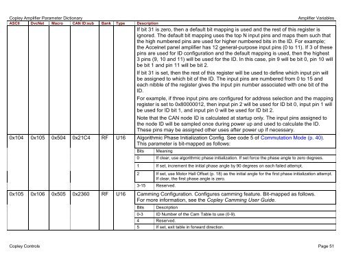
0x104 0x105 0x504 0x21C4 RF U16 Algorithmic Phase Initialization Config. See co<strong>de</strong> 5 of Commutation Mo<strong>de</strong> (p. 40).<br />
This <strong>parameter</strong> is bit-mapped as follows:<br />
Bits Meaning<br />
0 If clear, use algorithmic phase initialization. If set force the phase angle to zero <strong>de</strong>grees.<br />
1 If set, increment the initial phase angle by 90 <strong>de</strong>grees on each failed attempt.<br />
2 If set, use Motor Hall Offset (p. 18) as the initial angle for the first phase initialization attempt.<br />
If clear, the first phase angle is zero.<br />
3-15 Reserved.<br />
0x105 0x106 0x505 0x2360 RF U16 Camming Configuration. Configures camming feature. Bit-mapped as follows.<br />
For more information, see the <strong>Copley</strong> Camming User Gui<strong>de</strong>.<br />
Bits Description<br />
0-3 ID Number of the Cam Table to use (0-9).<br />
4 Reserved.<br />
5 If set, exit table in forward direction.<br />
<strong>Copley</strong> Controls Page 51