Copley amplifier parameter dictionary - Maccon.de
Copley amplifier parameter dictionary - Maccon.de
Copley amplifier parameter dictionary - Maccon.de

You also want an ePaper? Increase the reach of your titles
YUMPU automatically turns print PDFs into web optimized ePapers that Google loves.
<strong>Copley</strong> Amplifier Parameter Dictionary Amplifier Variables<br />
ASCII DvcNet Macro CAN ID:sub Bank Type Description<br />
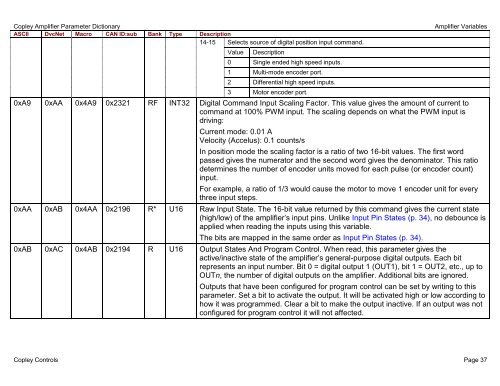
14-15 Selects source of digital position input command.<br />
Value Description<br />
0 Single en<strong>de</strong>d high speed inputs.<br />
1 Multi-mo<strong>de</strong> enco<strong>de</strong>r port.<br />
2 Differential high speed inputs.<br />
3 Motor enco<strong>de</strong>r port.<br />
0xA9 0xAA 0x4A9 0x2321 RF INT32 Digital Command Input Scaling Factor. This value gives the amount of current to<br />
command at 100% PWM input. The scaling <strong>de</strong>pends on what the PWM input is<br />
driving:<br />
Current mo<strong>de</strong>: 0.01 A<br />
Velocity (Accelus): 0.1 counts/s<br />
In position mo<strong>de</strong> the scaling factor is a ratio of two 16-bit values. The first word<br />
passed gives the numerator and the second word gives the <strong>de</strong>nominator. This ratio<br />
<strong>de</strong>termines the number of enco<strong>de</strong>r units moved for each pulse (or enco<strong>de</strong>r count)<br />
input.<br />
For example, a ratio of 1/3 would cause the motor to move 1 enco<strong>de</strong>r unit for every<br />
three input steps.<br />
0xAA 0xAB 0x4AA 0x2196 R* U16 Raw Input State. The 16-bit value returned by this command gives the current state<br />
(high/low) of the <strong>amplifier</strong>’s input pins. Unlike Input Pin States (p. 34), no <strong>de</strong>bounce is<br />
applied when reading the inputs using this variable.<br />
The bits are mapped in the same or<strong>de</strong>r as Input Pin States (p. 34).<br />
0xAB 0xAC 0x4AB 0x2194 R U16 Output States And Program Control. When read, this <strong>parameter</strong> gives the<br />
active/inactive state of the <strong>amplifier</strong>’s general-purpose digital outputs. Each bit<br />
represents an input number. Bit 0 = digital output 1 (OUT1), bit 1 = OUT2, etc., up to<br />
OUTn, the number of digital outputs on the <strong>amplifier</strong>. Additional bits are ignored.<br />
Outputs that have been configured for program control can be set by writing to this<br />
<strong>parameter</strong>. Set a bit to activate the output. It will be activated high or low according to<br />
how it was programmed. Clear a bit to make the output inactive. If an output was not<br />
configured for program control it will not affected.<br />
<strong>Copley</strong> Controls Page 37