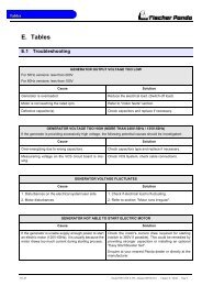
Manual
Manual
Manual

Create successful ePaper yourself
Turn your PDF publications into a flip-book with our unique Google optimized e-Paper software.
Boost capacitors<br />
Sample picture<br />
5.12.5 Connection to the AC on-board power supply<br />
5.12.5.1 Protective conductor<br />
Fig. 5.12.4-4: Boost capacitors<br />
Installation Instructions<br />
The generator is equipped with a PEN protective conductor system as standard (this means that the neutral conductor<br />
is also used as protective conductor).<br />
If a separate protective conductor is necessary (i. e. according to national safety regulations), the bridge circuit at the<br />
generator and the AC-Control box between null and generator housing has to be removed. Afterwards a separate<br />
protective conductor has to be installed and connected to all the system’s attached metallic housings.<br />
It is recommended to provide a voltage indication (voltmeter) and also a power indication, if applicable, in the installation<br />
system. The voltmeter (and power indication, if applicable) has to be installed behind the selector switch so<br />
that the voltage for every possible voltage source may be indicated. A separate voltmeter for the generator itself, is<br />
therefore not required.<br />
5.12.5.2 Electrical fuse<br />
It is absolutely essential that the electrical system installation is inspected by a qualified electrical technician. The<br />
generator should have its own AC input electrical fuse. This fuse should be sized so that the rated current of the generator<br />
on each of the individual phases is not exceeded by more than 25%.<br />
Data for gensets with power output greater than 30 kW on request!<br />
The fuses must be of the slow type. A 3-way motor protection switch must be installed to protect the electrical motor.<br />
Required fuse see Tabelle 9.6-1, “Nennströme,” auf Seite 219<br />
5.12.5.3 Required cable crosssections<br />
The following recommended electrical cable dimensions (cross sections) are the minimum required sizes for a safe<br />
installation. (see “Cable cross section” on page 208.)<br />
5.12.5.4 Disconnector - power source selector (three way cam switch)<br />
A power source selector switch must be installed between the generator (or if applicable, AC-Control box)<br />
and the ship's electrical supply system. This switch must ensure that all AC consumers can be switched off<br />
at once. This switch should also be installed to keep the generator and shore (grid) power systems sepa-<br />
Seite/Page 88 Panda_4000s_PMS_SCB_FCB_eng.R04 - Kapitel/Chapter 5: Installation Instructions 7.5.12