Manual
Manual
Manual

Create successful ePaper yourself
Turn your PDF publications into a flip-book with our unique Google optimized e-Paper software.
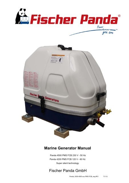
Marine Generator <strong>Manual</strong><br />
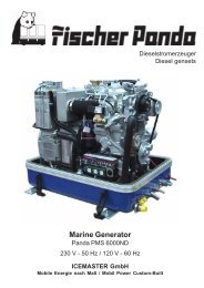
Panda 4500 PMS FCB 230 V - 50 Hz<br />
Panda 4200 PMS FCB 120 V - 60 Hz<br />
Super silent technology<br />
Fischer Panda GmbH<br />
Panda_4200-4500 eco PMS FCB_eng.R01 7.5.12
Erstellt durch / created by<br />
Fischer Panda GmbH - Leiter Technische Dokumentation<br />
Otto-Hahn-Str. 32-34<br />
33104 Paderborn - Germany<br />
Tel.: +49 (0) 5254-9202-0<br />
email: info@fischerpanda.de<br />
web: www.fischerpanda.de<br />
Current revision status<br />
Document<br />
Actual: Panda_4200-4500 eco PMS FCB_eng.R01_7.5.12<br />
Replace:<br />
Revision Page<br />
Copyright<br />
Duplication and change of the manual is permitted only in consultation with the manufacturer!<br />
Fischer Panda GmbH, 33104 Paderborn, reserves all rights regarding text and graphics. Details are given to the<br />
best of our knowledge. No liability is accepted for correctness. Technical modifications for improving the product<br />
without previous notice may be undertaken without notice. Before installation, it must be ensured that the pictures,<br />
diagrams and related material are applicable to the genset supplied. Enquiries must be made in case of doubt.<br />
Seite/Page 2 - Kaptitel/Chapter 1: 7.5.12
Inhalt / Contens<br />
Marine Generator <strong>Manual</strong>............................................................................................................................ ....... 1<br />
Current revision status................................................................................................................................ ....... 2<br />
1 General Instructions and Regulations .................................................................................................. ....... 8<br />
1.1 Safety first!...................................................................................................................................... ...... 8<br />
1.2 Tools .............................................................................................................................................. ..... 12<br />
1.3 Manufacturer declaration in accordance with the Machinery Directive 98/37/EC .......................... ..... 14<br />
1.4 Customer registration and guarantee ............................................................................................. .... 14<br />
1.4.1 Technical support ........................................................................................................... .... 14<br />
1.4.2 Caution, important information for start-up! .................................................................... .... 14<br />
1.5 Safety Instructions - Safety First! ................................................................................................... ..... 15<br />
1.5.1 Safe operation ................................................................................................................ .... 15<br />
1.5.2 Observe safety instructions! ........................................................................................... .... 15<br />
1.5.3 Personal protective clothing (PPE) ................................................................................. .... 15<br />
1.5.4 Cleanliness ensures safety ............................................................................................. .... 15<br />
1.5.5 Safe handling of fuels and lubricants .............................................................................. ..... 16<br />
1.5.6 Exhaust fumes and fire protection .................................................................................. .... 16<br />
1.5.7 Safety precautions against burns and battery explosions .............................................. ..... 17<br />
1.5.8 Protect your hands and body from rotating parts! .......................................................... .... 17<br />
1.5.9 Anti-freeze and disposal of fluids .................................................................................... .... 17<br />
1.5.10 Implementation of safety inspections and maintenance ................................................. ..... 18<br />
1.6 Warning and instruction signs......................................................................................................... .... 18<br />
1.6.1 Special instructions and hazards of generators .............................................................. .... 18<br />
1.6.1.1 Protective conductor and potential equalisation:.............................................. ..... 19<br />
1.6.1.2 Protective conductor for Panda AC generators:............................................... .... 19<br />
1.6.1.3 Switch off all loads while working on the generator ......................................... .... 19<br />
1.6.1.4 Potential equalisation for Panda AGT DC generators...................................... .... 19<br />
1.6.1.5 Safety instructions concerning cables.............................................................. ..... 20<br />
1.6.2 Recommended starter battery sizes ............................................................................... .... 20<br />
1.6.3 Important instructions for batteries - starter and/or traction batteries ............................. .... 20<br />
1.6.4 General safety instructions for handling batteries .......................................................... .... 21<br />
2 In case of Emergency First Aid / Im Notfall - Erste Hilfe ..................................................................... ..... 23<br />
2.7 WHEN AN ADULT STOPS BREATHING ...................................................................................... ..... 24<br />
3 Basics ...................................................................................................................................................... ..... 25<br />
3.1 Intended use of the machine .......................................................................................................... .... 25<br />
3.1.1 Purpose of the manual and description of the definitions trained person/operator/user .... 25<br />
3.1.1.1 Trained persons ............................................................................................... .... 25<br />
3.1.2 Operator ......................................................................................................................... .... 25<br />
3.1.2.1 User.................................................................................................................. .... 25<br />
3.2 Panda Transport Box...................................................................................................................... .... 26<br />
3.2.1 Bolted Fischer Panda Transport Box .............................................................................. .... 26<br />
3.2.2 Fischer Panda Transport Box with metal tab closure ..................................................... .... 26<br />
3.3 Transport and Loading/Unloading .................................................................................................. .... 26<br />
3.3.1 Transporting the generator ............................................................................................. .... 26<br />
3.3.2 Loading/unloading of the generator ................................................................................ .... 26<br />
3.4 Scope of delivery ............................................................................................................................ .... 27<br />
3.4.1 Asynchronous Generatoren: ........................................................................................... .... 27<br />
3.5 Opening the MPL sound insulation capsule ................................................................................... .... 29<br />
7.5.12 Inhalt/Contens Seite/Page 1
Inhalt / Contens<br />
3.5.1 Opening the GFK sound insulation capsule ................................................................... .... 30<br />
3.6 Special maintenance notes and arrangements at long periods of stand still time or shutdown...... .... 30<br />
3.6.1 Reference note for the starter battery at a long-term standstill ....................................... .... 31<br />
3.6.2 Arrangements at a short-term standstill .......................................................................... .... 31<br />
3.6.3 Arrangements at a medium-term standstill / winter storage ........................................... .... 31<br />
3.6.3.1 Arrangements for conservation: ....................................................................... .... 31<br />
3.6.3.2 Arrangements for deconservation after a medium-term standstill (3 to 6 months). 32<br />
3.6.4 Arrangements at a long-term standstill / shutdown ......................................................... .... 33<br />
3.6.4.1 Arrangements for conservation: ....................................................................... .... 33<br />
3.6.4.2 Arrangements after a long-term standstill (shutdown) / recommissioning (more than 6<br />
months): 34<br />
3.7 ........................................................................................................................................................ .... 34<br />
4 The Panda Generator.............................................................................................................................. ..... 35<br />
4.1 Type plate at the Generator ............................................................................................................ .... 35<br />
4.2 Description of the Generator 42000/4500 PMS .............................................................................. .... 36<br />
4.2.1 Right Side View 4200/4500 PMS .................................................................................... .... 36<br />
4.2.2 Left Side View 4200/4500 PMS ...................................................................................... .... 37<br />
4.2.3 Front View 4200/4500 PMS ............................................................................................ .... 38<br />
4.2.4 Back View 4200/4500 PMS ............................................................................................ .... 39<br />
4.2.5 View from above 42000/4500 PMS ................................................................................ .... 40<br />
4.3 Details of Functional Units ............................................................................................................. .... 41<br />
4.3.1 Remote Control Panel - see Remote Control Panel Datasheet ...................................... .... 41<br />
4.3.2 Components of Cooling System (Raw water + Fresh water) .......................................... .... 42<br />
4.3.3 Components of conbustion air ........................................................................................ .... 43<br />
4.3.4 Components of the Fuel System 4000s SC + 4000s FC ................................................ .... 44<br />
4.3.5 CSensors and Switches for Operation Surveillance ....................................................... .... 45<br />
4.3.6 Components of Oil Circuit 4000s SC + 4000s FC .......................................................... .... 46<br />
4.4 Operation manual .......................................................................................................................... ..... 48<br />
4.4.1 Preliminary remarks ........................................................................................................ .... 48<br />
4.4.2 Daily routine checks before starting ................................................................................ .... 48<br />
4.4.3 Starting Generator- see remote control panel datasheet ................................................ .... 49<br />
4.4.4 Stopping Generator - see remote control panel datasheet ............................................. .... 49<br />
5 Installation Instructions.......................................................................................................................... ..... 51<br />
5.1 Personal requirements.................................................................................................................... .... 51<br />
5.1.1 Hazard notes for the installation ..................................................................................... .... 51<br />
5.2 Place of installation ......................................................................................................................... .... 53<br />
5.2.1 Preliminary remark .......................................................................................................... .... 53<br />
5.2.2 Preparing the base - placement ...................................................................................... .... 53<br />
5.2.3 Advice for optimal sound insulation ................................................................................ .... 54<br />
5.3 Generator Connections - Scheme .................................................................................................. .... 54<br />
5.4 Installation of the cooling system - raw water ................................................................................. .... 54<br />
5.4.1 General information ........................................................................................................ .... 54<br />
5.4.2 Fischer Panda installation kit - raw water ....................................................................... .... 55<br />
5.4.3 Installation of the through hull fitting in Yachts - Schema ............................................... .... 56<br />
5.4.4 Quality of the raw water sucking in line .......................................................................... .... 56<br />
5.4.5 Generator installation above waterline ........................................................................... .... 57<br />
5.4.6 Raw water installation schema ....................................................................................... ..... 58<br />
5.4.7 Generator installation below waterline ............................................................................ .... 59<br />
Seite/Page 2 Inhalt/Contens 7.5.12
Inhalt / Contens<br />
5.5 Installation of the cooling system - fresh water............................................................................... .... 60<br />
5.5.1 Position of the external cooling water expansion tank .................................................... .... 60<br />
5.5.2 Scheme for Freshwater Circuit at Two Circuit Cooling System ...................................... ..... 61<br />
5.6 Installation of the water cooled exhaust system ............................................................................. .... 61<br />
5.6.1 Installation of the standard exhaust system ................................................................... .... 61<br />
5.7 .Installation of the waterlock ........................................................................................................... .... 63<br />
5.7.1 Possible cause for water in the exhaust hose ................................................................ .... 63<br />
5.7.1.1 Possible cause: Exhaust hose ......................................................................... .... 63<br />
5.7.1.2 Possible cause: cooling water hose ................................................................. .... 63<br />
5.7.2 Installation area of the waterlock .................................................................................... .... 64<br />
5.7.3 The volume of the waterlock ........................................................................................... .... 64<br />
5.7.3.1 Ideal position of the waterlock.......................................................................... ..... 66<br />
5.7.3.2 Example of the installation of the waterlock off-center and possible effects: ... ..... 68<br />
5.8 Exhaust / water separator............................................................................................................... .... 70<br />
5.8.1 Installation exhaust water separator ............................................................................... ..... 72<br />
5.9 Fuel system installation .................................................................................................................. .... 72<br />
5.9.1 Fischer Panda installation kit - Fuel system ................................................................... .... 72<br />
5.9.2 The following items need to be installed: ........................................................................ .... 74<br />
5.9.3 Connection of the fuel lines at the tank .......................................................................... .... 77<br />
5.9.4 Position of the pre-filter with water separator ................................................................. .... 78<br />
5.10 Generator DC system installation ................................................................................................... .... 78<br />
5.10.1 Connection of the starter battery block ........................................................................... .... 78<br />
5.10.2 How to connect two 12V batteries to a 24V battery bank ............................................... .... 82<br />
5.10.3 Connection of the remote control panel - see separate control panel manual ............... .... 83<br />
5.11 Generator AC System Installation .................................................................................................. .... 83<br />
5.12 AC-Control box with VCS and starting current limitation ................................................................ .... 83<br />
5.12.1 Installation with looped-in AC-Control box ...................................................................... .... 84<br />
5.12.2 Installation AC-Box / Distribution panel connected separately ....................................... .... 85<br />
5.12.3 Electronic voltage control VCS (not existent at ND models) .......................................... .... 86<br />
5.12.4 Alternative control: Mini-VCS .......................................................................................... ..... 86<br />
5.12.5 Connection to the AC on-board power supply ................................................................ .... 88<br />
5.12.5.1 Protective conductor ........................................................................................ .... 88<br />
5.12.5.2 Electrical fuse................................................................................................... .... 88<br />
5.12.5.3 Required cable crosssections .......................................................................... .... 88<br />
5.12.5.4 Disconnector - power source selector (three way cam switch) ........................ .... 88<br />
5.13 Special recommendations .............................................................................................................. .... 89<br />
5.13.1 Water sensor .................................................................................................................. .... 89<br />
5.14 Instructions on prevention of galvanic corrosion............................................................................. .... 89<br />
5.14.1 Instructions and measures on prevention of galvanic corrosion ..................................... .... 90<br />
5.15 Checking and filling of the oil circuit................................................................................................ .... 90<br />
5.15.1 First filling and ventilation of the internal cooling water circuit ........................................ .... 90<br />
5.15.1.1 Anti-freeze in the cooling water circuit ............................................................. .... 92<br />
5.15.2 Temperature check for controlling the cooling water circuit ........................................... .... 92<br />
5.15.3 Fresh water circuit at a two circuit cooling system - schema ......................................... .... 92<br />
5.16 Isolation test.................................................................................................................................... .... 93<br />
5.17 Initial Operation............................................................................................................................... .... 93<br />
6 Maintenance Instructions....................................................................................................................... ..... 95<br />
6.1 Personal requirements.................................................................................................................... .... 95<br />
7.5.12 Inhalt/Contens Seite/Page 3
Inhalt / Contens<br />
6.2 Hazard notes for the maintenance.................................................................................................. .... 95<br />
6.3 Environmental protection ................................................................................................................ .... 97<br />
6.4 Maintenance interval....................................................................................................................... .... 97<br />
6.5 General maintenance instructions .................................................................................................. .... 97<br />
6.5.1 Checks before starting .................................................................................................... .... 97<br />
6.5.2 Hose elements and rubber formed component in the sound cover ................................ .... 97<br />
6.6 For maintenance intervalls see „General information for PMS-Generators“The raw water circuit.. .... 98<br />
6.6.1 Clean raw water filter ...................................................................................................... .... 98<br />
6.7 Causes with frequent impeller waste .............................................................................................. .... 98<br />
6.7.1 Replacement of the impeller ........................................................................................... .... 98<br />
6.7.2 Replace the air filter mat ................................................................................................. .. 100<br />
6.7.3 Alternative replacement of the air filter mat with pull out holder ..................................... .. 101<br />
6.7.4 Alternative replacement of the air filter at housing with snap fasteners .......................... ... 103<br />
6.8 Checking oil-level............................................................................................................................ .. 104<br />
6.8.1 Refilling Oil ...................................................................................................................... .. 105<br />
6.8.2 After the oil level check and refilling the oil ..................................................................... .. 105<br />
6.9 Replacement of engine oil and engine oil filter ............................................................................... .. 106<br />
6.9.1 After the oil change ......................................................................................................... .. 108<br />
6.10 Verifying the starter battery and (if necessary) the battery bank..................................................... .. 109<br />
6.10.1 Battery ............................................................................................................................ .. 109<br />
6.10.1.1 Check battery and cable connections .............................................................. .. 109<br />
6.10.1.2 Check electrolyte level ..................................................................................... .. 109<br />
6.10.1.3 Check electrolyte density ................................................................................. .. 109<br />
6.11 Ventilating the fuel system .............................................................................................................. .. 110<br />
6.11.1 Replacement of the fuel filter .......................................................................................... .. 112<br />
6.11.1.1 Optional fuel filter with sight glass .................................................................... .. 112<br />
6.11.2 Check and discharge the capacitors ............................................................................... .. 113<br />
7 Generator Failure .................................................................................................................................... ... 115<br />
7.1 Personal requirements.................................................................................................................... .. 115<br />
7.2 Hazard notes for the troubleshooting.............................................................................................. .. 115<br />
7.3 Overloading the Generator ............................................................................................................. .. 116<br />
7.3.1 Effects of Short Circuiting and Overloading on the Generator ........................................ .. 117<br />
7.3.2 Overloading the Generator with Electric Motors ............................................................. .. 117<br />
7.3.3 Generator Voltage Fluctuations and Monitoring ............................................................. .. 117<br />
7.3.4 Automatic Voltage Monitoring and Auto-Shut Down ....................................................... .. 117<br />
7.4 Adjusting Instructions for the Spindle of the actuator (not ND models)........................................... .. 118<br />
7.4.1 Adjustment of the maximum upper speed ...................................................................... .. 118<br />
7.4.2 Adjustment of the normal speed limitation ...................................................................... .. 119<br />
7.4.3 Lubrication of the spiral thread spindle (not ND models) ................................................ .. 120<br />
7.4.4 Effects of a overload to the actuator (not ND models) .................................................... .. 120<br />
7.4.4.1 Possible disturbances in the area of the rev regulation „VCS“......................... .. 121<br />
7.4.4.2 Steps to check the voltage control by a disturbance: ....................................... .. 121<br />
7.4.4.3 If the actuator is not moving the following points are necessary: ..................... .. 121<br />
7.4.4.4 The mechanical voltage limitation must be checked regularly. The following steps have<br />
to be done: 122<br />
7.5 Low Generator-Output Voltage ....................................................................................................... .. 122<br />
7.6 Testing generator stator windings................................................................................................... .. 122<br />
7.6.1 Checking the generator voltage ...................................................................................... .. 122<br />
Seite/Page 4 Inhalt/Contens 7.5.12
Inhalt / Contens<br />
7.6.2 Measuring the coil resistance ......................................................................................... .. 123<br />
7.6.3 Checking the coil(s) to short-circuit ................................................................................ .. 123<br />
7.6.4 Measuring the inductive resistance ................................................................................ .. 123<br />
7.7 Starting Problems ........................................................................................................................... .. 124<br />
7.7.1 Fuel Solenoid Valve (optional) ........................................................................................ .. 124<br />
7.7.2 Failure Bypass Switch .................................................................................................... .. 124<br />
7.7.3 Stop solenoid .................................................................................................................. .. 125<br />
8 Tables....................................................................................................................................................... ... 127<br />
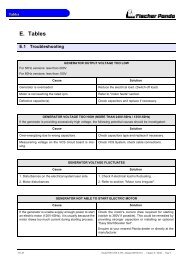
8.1 Troubleshooting .............................................................................................................................. .. 127<br />
8.2 Technical Data................................................................................................................................ .. 130<br />
8.3 Coolant specifications..................................................................................................................... .. 134<br />
8.3.1 Coolant mixture ratio ...................................................................................................... .. 135<br />
8.4 Fuel................................................................................................................................................. .. 135<br />
8.5 Engine oil ........................................................................................................................................ .. 135<br />
8.5.1 Engine oil classification .................................................................................................. .. 135<br />
8.5.1.1 Operating range: .............................................................................................. .. 135<br />
8.5.1.2 Quality of oil: .................................................................................................... .. 135<br />
9 Remote Control Panel P4 Control ........................................................................................................ ... 137<br />
9.1 Remote control panel...................................................................................................................... .. 137<br />
9.1.1 Cleaning and Replacing parts at the generator .............................................................. ... 138<br />
9.2 Front side ....................................................................................................................................... ... 139<br />
9.2.1 Back Side ....................................................................................................................... .. 139<br />
9.3 Operation <strong>Manual</strong> ........................................................................................................................... .. 140<br />
9.3.1 Preliminary Remarks ...................................................................................................... .. 140<br />
9.3.2 Override Function ........................................................................................................... .. 140<br />
9.3.3 Daily routine checks before starting ............................................................................... .. 140<br />
9.3.4 Starting the Generator .................................................................................................... .. 141<br />
9.3.5 Stopping Generator ........................................................................................................ .. 141<br />
9.4 Installation of the Panel .................................................................................................................. .. 142<br />
9.4.1 Connection of the remote control panel .......................................................................... .. 142<br />
9.5 Jumperconfiguration ....................................................................................................................... .. 143<br />
9.5.1 Jumper configuration for the input .................................................................................. .. 143<br />
9.5.2 Jumper J101-J103 .......................................................................................................... .. 143<br />
9.5.3 Jumper for configuraton odf the „Override“ time ............................................................. ... 145<br />
9.6 Maximum ratings ............................................................................................................................ .. 145<br />
7.5.12 Inhalt/Contens Seite/Page 5
Leere Seite / Intentionally blank<br />
Seite/Page 6 Kapitel/Chapter 1: 7.5.12
Dear Customer,<br />
Thank you for purchasing a Fischer Panda Generator and choosing Fischer Panda as your partner for mobile power<br />
on board. With your generator, you now have the means to produce your own power – wherever you are - and<br />
experience even greater independence. Not only do you have a Fischer Panda generator on board, you also have<br />
worldwide support from the Fischer Panda Team. Please take the time to read this and find how we can support you<br />
further.<br />
Installation Approval and Warranty<br />
Every generator has a worldwide warranty. You can apply for this warranty through your dealer when the installation<br />
is approved. If you have purchased an extended warranty, please ensure that it is kept in a safe place and that the<br />
dealer has your current address. Consult your dealer about warranty options especially if you have purchased a<br />
used generator. He will be able to advise about authorised Fischer Panda Services worldwide.<br />
Service and Support<br />
To ensure that your generator operates reliably, regular maintenance checks and tasks as specified in this manual<br />
must be carried out. Fischer Panda can supply Service Kits which are ideal for regular servicing tasks. We only<br />
supply the highest quality components which are guaranteed to be the RIGHT parts for your generator. Service<br />
“Plus” Kits are also available and ideal for longer trips where more than one service interval may be required.<br />
If you require assistance – please contact your Fischer Panda Dealer. Please do not attempt to undertake any repair<br />
work yourself, as this may affect your generator warranty. Your dealer will also be able to assist in finding your<br />
nearest Fischer Panda service station. Your nearest service station can also be found in our Global Service Network<br />
which can be downloaded from our homepage.<br />
Product Registration<br />
Please take the time to register your Fischer Panda Generator on our website at<br />
http://www.fischerpanda.de/mypanda<br />
By registering, you will ensure that you will be kept up to date on any technical upgrades or specific information on<br />
the operation or servicing of your generator. We can even let you know about new Fischer Panda products –<br />
especially helpful if you are planning to upgrade or expand your installation at a later date.<br />
Fischer Panda Quality - Tried and Tested<br />
DIN-certified according DIN ISO 9001<br />
Thank you for purchasing a Fischer Panda Generator.<br />
Your Fischer Panda Team<br />
Seite/Page 7 7.5.12
1. General Instructions and Regulations<br />
1.1 Safety first!<br />
General Instructions and Regulations<br />
These symbols are used throughout this manual and on labels on the machine itself to warn of the possibility of<br />
personal injury of lethal danger during certain maintenance work or operations. Read these instructions carefully.<br />
Can cause acute or chronic health impairments or death<br />
even in very small quantities if inhaled, swallowed, or<br />
absorbed through the skin.<br />
This warning symbol draws attention to special warnings,<br />
instructions or procedures which, if not strictly observed, may<br />
result in damage or destruction of equipment.<br />
Warning of materials that may ignite in the presence of an<br />
ignition source (cigarettes, hot surfaces, sparks, etc.).<br />
In the environment described / during the work specified,<br />
smoking is prohibited.<br />
Fire and naked light are ignition sources that must be<br />
avoided.<br />
The equipment shall not be activated or started up while work<br />
is in progress.<br />
WARNING: Hazardous materials<br />
WARNING: Important information!<br />
WARNING: Fire hazard<br />
PROHIBITED: No smoking<br />
PROHIBITED: No fire or naked light<br />
PROHIBITED: Do not activate/start up<br />
Seite/Page 8 - Kaptitel/Chapter 1: General Instructions and Regulations 7.5.12
General Instructions and Regulations<br />
Touching of the corresponding parts and systems is<br />
prohibited.<br />
An external signal may trigger an automatic start-up.<br />
This danger symbol refers to the danger of electric shock and<br />
draws attention to special warnings, instructions or<br />
procedures which, if not strictly observed, may result in<br />
severe personal injury or loss of life due to electric shock.<br />
General warning of a hazard area<br />
Can cause acute or chronic health impairments or death<br />
even in very small quantities if inhaled or ingested.<br />
Warning of live parts that may cause electric shock upon<br />
contact. Especially dangerous for persons with heart<br />
problems or pacemakers.<br />
Danger of injury due to being pulled into equipment. Bruising<br />
and torn off body parts possible. Risk of being pulled in when<br />
touching with body part, loose-fitting clothing, scarf, tie, etc.<br />
PROHIBITED: Do not touch<br />
DANGER: Automatic start-up<br />
WARNING: Hazardous electric voltage<br />
WARNING: General warning<br />
WARNING: Danger due to inhalation and/or<br />
ingestion<br />
WARNING: Risk of electric shock upon contact<br />
WARNING: Danger due to rotating parts<br />
7.5.12 Kapitel/Chapter 1: General Instructions and Regulations - Seite/Page 9
Warning of substances that may cause an explosion under<br />
certain conditions, e.g. presence of heat or ignition sources.<br />
Warning of hot surfaces and liquids. Burn/scalding hazard.<br />
Warning of substances that cause chemical burns upon<br />
contact. These substances can act as contaminants if<br />
introduced into the body.<br />
When the system is opened, the pressure can be relieved<br />
abruptly and expel hot gases and fluids. Risk of injury due to<br />
parts flying about, burn hazard due to liquids and gases.<br />
General Instructions and Regulations<br />
WARNING: Explosion hazard<br />
WARNING: Hot surface<br />
WARNING: Danger due to corrosive substances,<br />
potential contamination of person<br />
WARNING: System may be pressurised!<br />
WARNING: Hearing damage<br />
WARNING: Magnetic field<br />
WARNING: Overpressure<br />
Seite/Page 10 - Kaptitel/Chapter 1: General Instructions and Regulations 7.5.12
General Instructions and Regulations<br />
Wearing the applicable snugly fitting protective clothing<br />
provides protection from hazards and can prevent damage to<br />
your health.<br />
Wearing hearing protection provides protection from acute<br />
and gradual hearing loss.<br />
Wearing safety goggles protects the eyes from damage.<br />
Optical spectacles are not a replacement for the<br />
corresponding safety goggles.<br />
Wearing protective gloves provides the hands from hazards<br />
like friction, graze, punctures or deep cuts and protects them<br />
from contact with hot surfaces.<br />
Compliance with the instructions in the manual can avert<br />
danger and prevent accidents. This will protect you and the<br />
generator.<br />
Environmental protection saves our living environment. For<br />
you and for your children.<br />
MANDATORY INSTRUCTION: Wear snugly fitting<br />
protective clothing (PPE).<br />
MANDATORY INSTRUCTION: Wear hearing<br />
protection (PPE).<br />
MANDATORY INSTRUCTION: Wear safety<br />
goggles (PPE).<br />
MANDATORY INSTRUCTION: Wear protective<br />
gloves (PPE).<br />
MANDATORY INSTRUCTION: Observe the<br />
instructions in the manual.<br />
MANDATORY INSTRUCTION: Comply with<br />
environmental protection requirements.<br />
7.5.12 Kapitel/Chapter 1: General Instructions and Regulations - Seite/Page 11
1.2 Tools<br />
General Instructions and Regulations<br />
These symbols are used throughout this manual to show which tool must be used for maintenance or installation.<br />
Spanners<br />
W.A.F X = width across flats of X mm<br />
Hook wrench for oil filter<br />
Screw driver, for slotted head screws and for Phillips head screws<br />
Multimeter, multimeter with capacitor measuring unit<br />
Socket wrench set<br />
Hexagon socket wrench set<br />
Seite/Page 12 - Kaptitel/Chapter 1: General Instructions and Regulations 7.5.12
General Instructions and Regulations<br />
Clamp-on ammeter (DC for synchronous generators; AC for asynchronous<br />
generators)<br />
Torque wrench<br />
7.5.12 Kapitel/Chapter 1: General Instructions and Regulations - Seite/Page 13
General Instructions and Regulations<br />
1.3 Manufacturer declaration in accordance with the Machinery Directive<br />
98/37/EC<br />
Manufacturer declaration in accordance with the Machinery Directive 98/37/EC<br />
The generator was designed in such a way that all assemblies correspond with the CE guidelines. If Machinery<br />
Directive 98/37/EC is applied, then it is forbidden to start the generator until it has been ascertained that the system<br />
into which the generator is to be integrated also complies with the Machinery Directive 98/37/EC. This includes the<br />
exhaust system, cooling system and electrical installations.<br />
The evaluation of „protection against contact“ must be carried out when installed, in conjunction with the respective<br />
system. This also includes correct electrical connections, a safe ground wire connection, foreign body and humidity<br />
protection, protection against moisture due to excessive condensation, as well as overheating through appropriate<br />
and inappropriate use of the equipment in its installed state. The responsibility for implementing these measures lies<br />
with those who undertake the installation of the generator in the final system.<br />
1.4 Customer registration and guarantee<br />
Use the advantages of registering your product:<br />
• you will receive a Guarantee Certificate after approval of your installation data<br />
• you will receive extended product information that may be relevant to safety.<br />
• You will receive free upgrades as necessary.<br />
Additional advantages:<br />
Based on your complete data record, Fischer Panda technicians can provide you with fast assistance, since 90% of<br />
the disturbances result from defects in the periphery.<br />
Problems due to installation errors can be recognized in advance.<br />
1.4.1 Technical support<br />
Technical Support via the Internet: info@fischerpanda.de<br />
1.4.2 Caution, important information for start-up!<br />
1. The commissioning log shall be filled in immediately after initial operation and shall be confirmed by signature.<br />
2. The commissioning log must be received by Fischer Panda GmbH at Paderborn within 4 weeks of initial<br />
operation.<br />
3. After receiving the commissioning log, Fischer Panda will make out the official guarantee certificate and send it to<br />
the customer.<br />
4. If warranty claims are made, the document with the guarantee certification must be submitted.<br />
If the above requirements are not or only partly fulfilled, the warranty claim shall become void.<br />
Seite/Page 14 - Kaptitel/Chapter 1: General Instructions and Regulations 7.5.12
General Instructions and Regulations<br />
1.5 Safety Instructions - Safety First!<br />
1.5.1 Safe operation<br />
Careful handling of the equipment is the best insurance against an accident. Read the manual<br />
diligently, and make sure you understand it before starting up the equipment. All operators,<br />
regardless of their experience level, shall read this manual and additional pertinent manuals before<br />
commissioning the equipment or installing an attachment. The owner shall be responsible for<br />
ensuring that all operators receive this information and are instructed on safe handling practices.<br />
1.5.2 Observe safety instructions!<br />
Read and understand this manual and the safety instructions on the generator before trying to start up and operate<br />
the generator. Learn the operating practices and ensure work safety. Familiarise yourself with the equipment and its<br />
limits. Keep the generator in good condition.<br />
1.5.3 Personal protective clothing (PPE)<br />
For maintenance and repair work on the equipment, do not wear loose, torn, or ill-fitting clothing<br />
that may catch on protruding parts or come into contact with pulleys, cooling disks, or other rotating<br />
parts, which can cause severe injury.<br />
Wear appropriate safety and protective clothing during work.<br />
Do not operate the generator while under the influence of alcohol, medications, or drugs.<br />
Do not wear head phones or ear buds while operating, servicing, or repairing the equipment.<br />
1.5.4 Cleanliness ensures safety<br />
Keep the generator and its environment clean.<br />
Before cleaning the generator, shut down the equipment and secure it against accidental start-up.<br />
Keep the generator free from dirt, grease, and waste. Store flammable liquids in suitable<br />
containers only and ensure adequate distance to the generator. Check the lines regularly for<br />
leakage and eliminate leaks immediately as applicable.<br />
7.5.12 Kapitel/Chapter 1: General Instructions and Regulations - Seite/Page 15
1.5.5 Safe handling of fuels and lubricants<br />
General Instructions and Regulations<br />
Keep fuels and lubricants away from naked fire.<br />
Before filling up the tank and/or applying lubricant, always shut down the generator and secure it<br />
against accidental start-up.<br />
Do not smoke and avoid naked flame and sparking near fuels and the generator. Fuel is highly<br />
flammable and may explode under certain conditions.<br />
Refuel in well-ventilated open spaces only. If fuel/lubricant was spilled, eliminate fluids<br />
immediately.<br />
Do not mix diesel fuel with petrol or alcohol. Such a mixture can cause fire and will damage the<br />
generator.<br />
Use only approved fuel containers and tank systems. Old bottles and canisters are not adequate.<br />
1.5.6 Exhaust fumes and fire protection<br />
Engine fumes can be hazardous to your health if they accumulate. Ensure that the generator<br />
exhaust fumes are vented appropriately (leak-proof system), and that an adequate fresh air<br />
supply is available for the generator and the operator (forced ventilation).<br />
Check the system regularly for leakage and eliminate leaks as applicable.<br />
Exhaust gases and parts containing such fumes are very hot; they may cause burns under<br />
certain circumstances. Always keep flammable parts away from the generator and the exhaust<br />
system.<br />
To prevent fire, ensure that electrical connections are not short-circuited. Check regularly that all<br />
lines and cables are in good condition and that there is no chafing. Bare wires, open chafing spots,<br />
frayed insulation, and loose cable connections can cause dangerous electric shocks, short-circuit,<br />
and fire.<br />
The generator shall be integrated in the existing fire safety system by the operating company.<br />
CALIFORNIA<br />
Proposition 65 Warning<br />
Diesel engine exhaust and some of its constituents are known to the State of<br />
California to cause cancer, birth defects, and other reproductive harm.<br />
Exhaust gases from diesel motors and some components are carcinogenic and can cause<br />
deformities and other genetic defects.<br />
Seite/Page 16 - Kaptitel/Chapter 1: General Instructions and Regulations 7.5.12
General Instructions and Regulations<br />
1.5.7 Safety precautions against burns and battery explosions<br />
The generator and its cooling agents and lubricants as well as the fuel can get hot while the<br />
generator is operated. Use caution around hot components such as parts containing exhaust<br />
fumes, radiator, hoses, and engine block during operation and after the generator was shut<br />
down.<br />
The cooling system may be pressurised. Open the cooling system only after letting the engine<br />
and the coolant cool down. Wear appropriate protective clothing (e.g. safety goggles, gloves).<br />
Prior to operation, ensure that the cooling system is sealed and that all hose clamps are<br />
tightened.<br />
The battery represents an explosion hazard, this applies both to the starter battery and the<br />
battery bank of the AGT generators. While batteries are being charged, a hydrogen-oxygen<br />
mixture is generated, which is highly explosive (electrolytic gas).<br />
Do not use or charge batteries if the fluid level is below the MINIMUM marking. The life span of<br />
the battery is significantly reduced, and the risk of explosion increases. Refill to a fluid level<br />
between maximum and minimum level without delay.<br />
Especially during charging, keep sparks and naked fire away from the batteries. Ensure that the<br />
battery terminals are tightly connected and not corroded to avoid sparking. Use an appropriate<br />
terminal grease.<br />
Check the charge level with an adequate voltmeter or acid siphon. Contact of a metal object<br />
across the terminals will result in short-circuiting, battery damage, and high explosion risk.<br />
Do not charge frozen batteries. Heat the batteries to +16 °C (61 °F) prior to charging.<br />
1.5.8 Protect your hands and body from rotating parts!<br />
Always keep the capsule closed while operating the generator.<br />
To check the V-belt tension, always shut down the generator.<br />
Keep your hands and body away from rotating parts such as V-belt, fans, pulleys, and flywheel.<br />
Contact can cause severe injury.<br />
Do not run the engine without the safety devices in place. Prior to start-up, mount all safety<br />
devices securely and check for proper attachment and function.<br />
1.5.9 Anti-freeze and disposal of fluids<br />
Anti-freeze contains toxic substances. To prevent injury, wear rubber gloves and wash off any<br />
anti-freeze immediately in case of skin contact. Do not mix different anti-freeze agents. The<br />
mixture may cause a chemical reaction generating harmful substances. Use only anti-freeze that<br />
was approved by Fischer Panda.<br />
Protect the environment. Collect drained fluids (lubricants, anti-freeze, fuel), and dispose of them<br />
properly. Observe the local regulations for the respective country. Ensure that no fluids (not even<br />
very small quantities) can drain into the soil, sewers, or bodies of water.<br />
7.5.12 Kapitel/Chapter 1: General Instructions and Regulations - Seite/Page 17
1.5.10 Implementation of safety inspections and maintenance<br />
General Instructions and Regulations<br />
Disconnect the battery from the engine before performing service work. Affix a sign to the control<br />
panel - both the main and the corresponding slave panel - with the instruction „ DO NOT START UP<br />
- MAINTENANCE IN PROGRESS“ to prevent unintentional start-up.<br />
To prevent sparking due to accidental short-circuiting, always remove the earthing cable (-) first and<br />
reconnect it last. Do not start work until the generator and all fluids and exhaust system parts have<br />
cooled down.<br />
Use only suitable tooling and appliances and familiarise yourself with their functions to prevent<br />
secondary damage and/or injury.<br />
Always keep a fire extinguisher and a first aid box handy while performing maintenance work.<br />
1.6 Warning and instruction signs<br />
Keep warning and instruction signs clean and legible.<br />
Clean the signs with water and soap and dry them with a soft cloth.<br />
Immediately replace damaged or missing warning and instruction signs. This also applies to the installation of spare<br />
parts.<br />
1.6.1 Special instructions and hazards of generators<br />
The electrical installations may only be carried out by trained and qualified personnel!<br />
The generator must not be operated with the cover removed.<br />
If the generator is being installed without a sound insulation capsule, it must be ensured that all<br />
rotating parts (belt-pulley, belts etc.) are covered and protected so that there is no danger to life<br />
and body!<br />
If a sound insulation covering will be produced at the place of installation, then easily visible signs<br />
must show that the generator must only be switched on while the capsule is closed.<br />
All servicing, maintenance, or repair work may only be carried out when the motor is not running.<br />
Electrical voltages above 48 volts (battery chargers greater than 36 volts) are always dangerous<br />
to life. The rules of the respective regional authority must be adhered to during installation. For<br />
safety reasons, only an electrician may carry out the installation of the electrical connections of<br />
the generator.<br />
Seite/Page 18 - Kaptitel/Chapter 1: General Instructions and Regulations 7.5.12
General Instructions and Regulations<br />
1.6.1.1 Protective conductor and potential equalisation:<br />
Electric current below 48 V may be life-threatening. Fort this reason systems are grounded with a protective<br />
conductor. In connection with a RCD the current supply will be disconnected in case of a failure.<br />
Appropriate safety precautions like the RCD and corresponding fuses have to be provided by the customer<br />
to guarantee a save operation of the generator.<br />
1.6.1.2 Protective conductor for Panda AC generators:<br />
The generator is „earthed“ as a standard (centre and ground are interconnected in the generator<br />
terminal box by a shunt). This is a basic first-level safety measure, which offers protection as long<br />
as no other measures are installed. Above all, it is designed for delivery and a possible test run.<br />
This „neutralisation“ (Protective Earthing Neutral - PEN) is only effective if all parts of the electrical<br />
system are jointly „earthed“ to a common potential. The shunt can be removed if this is necessary<br />
for technical reasons and another protective system has been set up instead.<br />
While the generator is being operated, the full voltage is applied to the AC control box, as<br />
well. Therefore, it is essential to ensure that the control box is closed and secured against<br />
touch while the generator is running.<br />
The battery must always be disconnected if work on the generator or electrical system is to<br />
be carried out, so that the generator cannot be started up unintentionally.<br />
1.6.1.3 Switch off all loads while working on the generator<br />
All loads must be disconnected prior to working on the generator to avoid damage to the devices. In addition, the<br />
semiconductor relays in the AC control box must be disconnected in order to avoid the booster capacitors being<br />
activated during set-up. The negative terminal of the battery must be disconnected.<br />
Capacitors are required to run the generator. These have two varying functions:<br />
A) The working capacitors<br />
B) The booster capacitors<br />
Both groups are located in a separate AC control box.<br />
Capacitors store electrical energy. High voltages may remain across the capacitor contacts even after they have<br />
been disconnected from the mains. As a safety precaution, do not touch the contacts. If the capacitors must be<br />
replaced or inspected, the contacts shall be short-circuited by connecting an electrical conductor to discharge<br />
potentially remaining potential differences.<br />
If the generator is switched off normally, the working capacitors are automatically discharged via the winding of the<br />
generator. The booster capacitors are discharged by means of internal discharge resistors.<br />
For safety reasons, all capacitors must be discharged through short-circuiting before work is carried out on the AC<br />
control box.<br />
1.6.1.4 Potential equalisation for Panda AGT DC generators<br />
For further information specific to your generator, see the chapter installation.<br />
7.5.12 Kapitel/Chapter 1: General Instructions and Regulations - Seite/Page 19
1.6.1.5 Safety instructions concerning cables<br />
Cable types<br />
General Instructions and Regulations<br />
It is recommended to use cables that are in compliance with the standard UL 1426 (BC-5W2) with type 3 (ABYC<br />
section E-11).<br />
Cable cross-section<br />
The cable shall be selected taking into account the amperage, cable type, and conductor length (from the positive<br />
power source connection to the electrical device and back to the negative power source connection).<br />
Cable installation<br />
It is recommended to install a self-draining cable conduit classified as V-2 or higher in compliance with UL 94 in the<br />
area of the cable guide inside the capsule. It must be ensured that the cable guide is not routed along hot surfaces<br />
such as the exhaust manifold or the engine oil drain screw but instead is installed free from any influence due to<br />
friction and crushing.<br />
1.6.2 Recommended starter battery sizes<br />
Use only batteries approved by the manufacturer as starter batteries.<br />
Use the battery capacity recommended by the engine manufacturer.<br />
ATTENTION!<br />
Prior to installation, verify that the voltage of the starter battery complies with the start-up system<br />
voltage.<br />
e.g. 12 V starter battery for 12 V start-up system<br />
e.g. 24 V starter battery for 24 V start-up system (e. g. 2x 12 V in series)<br />
1.6.3 Important instructions for batteries - starter and/or traction batteries<br />
ATTENTION!!! Start-up:<br />
Installation of battery connection lines.<br />
Observe the instructions installation guidelines of the battery manufacturer.<br />
Observe the regulations „ABYC regulation E11 AC and DC electrical systems on boats“ a/or EN<br />
ISO 10133:2000 „Small craft -- Electrical systems -- Extra-low-voltage DC installations“ as<br />
applicable!<br />
The battery compartment and the corresponding installation shall be dimensioned<br />
adequately.<br />
The batteries can be separated mechanically or with an adequate power relay.<br />
Seite/Page 20 - Kaptitel/Chapter 1: General Instructions and Regulations 7.5.12
General Instructions and Regulations<br />
Observe the applicable instructions concerning fire and explosion protection of the battery<br />
manufacturer.<br />
Install a fuse of appropriate size in the positive connection of the starter battery. Install as close to<br />
the battery as possible but with a max. distance of 300 mm (12 in) from the battery.<br />
The cable from the battery to the fuse shall be protected with a conduit/protective sleeve against<br />
fraying.<br />
Use self-extinguishing and fire-protected cables for installation that are designed for max. temperatures of 90 °C,<br />
195 °F.<br />
Install the battery cables in such a way that the insulation cannot be removed by chafing or other mechanical<br />
stresses.<br />
The battery terminals must be protected against accidental short-circuiting.<br />
Inside the Fischer Panda generator capsule, the positive battery cable must be routed so that it is protected from<br />
heat and vibrations by means of an adequate conduit/protective sleeve. It must be installed so that it does not come<br />
into contact with rotating parts or such that heat up during operation such as pulley, exhaust manifold, exhaust pipe,<br />
and motor itself. Do not overtighten the cable, as it may be damaged otherwise.<br />
After completing the installation, perform a test run of the generator and check the battery cable installation during<br />
and after the test run. Implement corrections as necessary.<br />
Fig. 1.6-1: Sample diagram for starter battery installation<br />
1.6.4 General safety instructions for handling batteries<br />
These instructions shall apply in addition to the instructions of the battery manufacturer:<br />
• While you are working on the batteries, a second person should be within earshot to help you if<br />
necessary.<br />
• Keep water and soap ready in case battery acid is burning your skin.<br />
• Wear eye protection and protective clothing. Do not touch your eyes while handling batteries.<br />
7.5.12 Kapitel/Chapter 1: General Instructions and Regulations - Seite/Page 21
• If you have acid splashes on the skin or clothing, wash them out with lots of water and soap.<br />
• If acid sprays into your eyes, immediately flush them with clean water until no more burning is<br />
felt. Immediately seek medical assistance.<br />
• Do not smoke near the batteries. Avoid naked fire. The area around batteries is a potentially<br />
explosive atmosphere.<br />
• Ensure that no tools are dropped on the battery terminals; cover them as necessary.<br />
• Do not wear jewellery or watches on your arms during installation that might short-circuit the<br />
battery. Otherwise, there is a risk of skin burns.<br />
• Protect all battery contacts against accidental contact.<br />
• For battery banks: Use only deep cycle batteries. Starter batteries are not suitable. Lead-acid<br />
gel batteries are recommended. They are maintenance-free, cycle stable, and do not release<br />
gases.<br />
• Never charge a frozen battery.<br />
• Avoid battery short-circuits.<br />
• Ensure proper ventilation of the battery to vent gases that may be released.<br />
• Battery connection terminals must be checked for proper seating before operation.<br />
• Battery connection cables shall be installed with utmost care and shall be checked for excessive<br />
heating under load. Check the battery near vibrating components regularly for chafing and<br />
insulation defects.<br />
ATTENTION! For battery charger generators (Fischer Panda AGT-DC)!<br />
Prior to installation, verify that the voltage of the battery bank complies with the output<br />
voltage of the generator.<br />
General Instructions and Regulations<br />
Seite/Page 22 - Kaptitel/Chapter 1: General Instructions and Regulations 7.5.12
In case of Emergency First Aid / Im Notfall -<br />
Erste Hilfe<br />
2. In case of Emergency First Aid / Im Notfall - Erste Hilfe<br />
1<br />
12<br />
13<br />
14<br />
15<br />
First Aid in case of accidents by electrical shocks<br />
5 Safety steps to follow if someone is the victim of electrical shock<br />
Do not touch the injured person while the generator is running.<br />
Switch off the generator immediately.<br />
If you cannot switch off the generator, pull, push, or lift the person to safety using a<br />
wooden pole, rope or some nonconducting material.<br />
Call an emergency doctor as soon as possible.<br />
Immediately start necessary first aid procedures.<br />
7.5.12 Kapitel/Chapter 2: In case of Emergency First Aid / Im Notfall - Erste Hilfe Seite/Page 23
2.7 WHEN AN ADULT STOPS BREATHING<br />
DO NOT attempt to perform the rescue breathing<br />
techniques provided on this page, unless certified.<br />
Performance of these techniques by uncertified<br />
personnel could result in further injury or death to the<br />
victim.<br />
1 Does the Person Respond?<br />
Tap or gently shake victim.<br />
Shout, „Are you OK?“<br />
3 Roll Person onto Back.<br />
Roll victim towards you by pulling slowly.<br />
4 Open Airway.<br />
Tilt head back, and lift chin.<br />
Shout, „Are you OK?“<br />
6 Give 2 Full Breaths.<br />
Keep head tilted back.<br />
Pinch nose shut.<br />
Seal your lips tight around victim's mouth.<br />
Give 2 full breaths for 1 to 1½ seconds each.<br />
7 Check for Pulse at side of Neck.<br />
Feel for pulse for 5 to 10 seconds.<br />
9 Begin Rescue Breathing.<br />
Keep head tilted back.<br />
Lift chin.<br />
Pinch nose shut.<br />
Give 1 full breath every 5 seconds.<br />
Look, listen, and feel for breathing between breaths.<br />
In case of Emergency First Aid / Im Notfall -<br />
Erste Hilfe<br />
Warning:<br />
2 Shout, „Help!“<br />
Call people who can phone for help.<br />
5 Check for Breathing.<br />
Look, listen, and feel for breathing for 3 to 5<br />
seconds.<br />
8 Phone EMS for Help.<br />
Send someone to call an ambulance.<br />
10 Recheck Pulse Every Minute.<br />
Keep head tilted back.<br />
Feel for pulse for 5 to 10 seconds.<br />
If victim has pulse, not breathing, continue<br />
rescue breathing. If no pulse, begin CPR.<br />
Seite/Page 24 Kapitel/Chapter 2: In case of Emergency First Aid / Im Notfall - Erste Hilfe 7.5.12
3. Basics<br />
3.1 Intended use of the machine<br />
The Fischer Panda generator is made to produce electrical energy out of diesel fuel.<br />
The diesel fuel is converted to mechanical energy by the diesel engine. This mechanical energy drives the generator.<br />
In the genset, the mechanical energy is converted to electrical energy. This process is controlled by (sometimes<br />
external) components, the remote control panel and the voltage control system (VCS).<br />
For the process is a sufficient amount of fuel and combustion air necessary. Arising exhaust and heat must be lead<br />
away.<br />
If the electrical power should be applied to a local net, The regulation and installation instructions of the Net owner<br />
and the regional authorities must be respected. This includes lightening conductor, personal protection switch etc.<br />
Misapplication of the Product can damage and destroy the product and the electrical net inclusive all load which is<br />
attached to the net, and contain hazards like short circuit. It is not allowed to modify the product in any case. Never<br />
open the sound cover during operation. The safety and hazard notes of the manual must be respected.<br />
3.1.1 Purpose of the manual and description of the definitions trained person/operator/<br />
user<br />
This manual is work instruction and operation instruction for the owner and user of Fischer Panda generators.<br />
The manual is the base and the guideline for the correct installation and maintenance of Fischer Panda Generators.<br />
The manual does not substitute the technical evaluation and should be used as an example guide only.<br />
The installation must be undertaken and proved by a suitable qualified/trained person and may in accordance with<br />
the law as required by the country and special situation.<br />
3.1.1.1 Trained persons<br />
Trained persons for the mechanical components are motor mechanics or persons with similar education<br />
and training.<br />
Trained persons for the electrical components are electricians or persons with similar education and training.<br />
After the Installation, the trained person must instruct the owner for operation and maintenance of the generator.<br />
This must include the hazards of the generator use.<br />
3.1.2 Operator<br />
The operator is the for the operation of the generator responsible person.<br />
After the installation, the operator must be instructed for the operation ad maintenance of the generator. This must<br />
include the hazards during operation of the generator and a instruction for the maintenance.<br />
The operator must read and follow the manual and must respect the hazard notes and safety instructions.<br />
3.1.2.1 User<br />
Users are persons, established by the operator, to operate the generator.<br />
The operator must assure that the user read and understand the manual and that all hazard notes and safety<br />
instructions are respected. The user must be instructed by the operator regarding his activity at the generator.<br />
7.5.12 Grundlagen_deu.R01 - Kapitel/Chapter 3: Seite/Page 25
3.2 Panda Transport Box<br />
3.2.1 Bolted Fischer Panda Transport Box<br />
1. Remove the bolts for cover / sidewalls<br />
2. Remove the cover<br />
3. Remove the loose accessories<br />
4. Remove the bolts for sidewalls / floor pallet<br />
5. Remove the sidewalls<br />
6. Open the generator attachment<br />
3.2.2 Fischer Panda Transport Box with metal tab closure<br />
1. Bend up the metal tab closures on the transport box lid.<br />
2. Remove the cover<br />
3. Remove the loose<br />
4. Bend open the metal tab closures on the transport box bottom.<br />
5. Remove the sidewalls<br />
6. Open the generator attachment<br />
3.3 Transport and Loading/Unloading<br />
3.3.1 Transporting the generator<br />
• The generator must always be upright for transport.<br />
• For transport, the Fischer Panda Transport Box shall be used for the generator. The generator shall be securely<br />
attached to the bottom of the box.<br />
• For loading/unloading, an adequate industrial truck shall be used.<br />
• Depending on the transport distance (e.g. air cargo), the generator fluids (coolant, engine oil, fuel) may have to be<br />
drained. The corresponding instructions and warnings must be fitted to the transport packaging.<br />
3.3.2 Loading/unloading of the generator<br />
For loading/unloading the generator, appropriate ring eye bolts shall be installed in the holes in the support rails. The<br />
load bearing capacity of each ring eye bolt must at least equal the generator weight.<br />
Seite/Page 26 Grundlagen_deu.R01 - Kapitel/Chapter 3: 7.5.12
An adequate lifting yoke shall be used for transport/<br />
loading<br />
3.4 Scope of delivery<br />
The Fischer Panda PMS generator system contains following components:<br />
3.4.1 Asynchronous Generatoren:<br />
Fischer Panda Generator<br />
representative picture<br />
Remote control panel<br />
representative picture<br />
Fig. 3.3-1: Lifting yoke (example)<br />
Fig. 3.4-1: Fischer Panda Generator<br />
Fig. 3.4-2: Remote control panel<br />
7.5.12 Grundlagen_deu.R01 - Kapitel/Chapter 3: Seite/Page 27
AC Control Box<br />
The AC Control Box contains the capacitors and the control<br />
circuit board (VCS) for the generator.<br />
At ND generators and generators with mini VCS the capacitors<br />
and the VCS may mounted at the generator. The AC<br />
Control Box is not required for this generators.<br />
representative picture<br />
Fischer Panda <strong>Manual</strong><br />
The Fischer Panda <strong>Manual</strong> contains following components:<br />
- Clear foil bag with general informations ect.<br />
- Generator manual with added remote control panel manual<br />
- Spare part catalogue „Installation & Service Guide“<br />
- Engine manual from the engine manufacturer.<br />
- Wiring diagram for the generator<br />
representative picture<br />
Fig. 3.4-3: AC Control Box<br />
Fig. 3.4.1-4: Fischer Panda <strong>Manual</strong><br />
Seite/Page 28 Grundlagen_deu.R01 - Kapitel/Chapter 3: 7.5.12
Optionales components<br />
f.e.:<br />
- Fuel pump<br />
- Installation kit<br />
- Water lock<br />
- ect.<br />
3.5 Opening the MPL sound insulation capsule<br />
To open the sound insulation capsule, the closures must<br />
be rotated roughly 180° counter-clockwise. Use a flat<br />
head screwdriver. Pull the sidewalls out by gripping into<br />
the slots.<br />
Closure locked<br />
Fig. 3.5-1: Sound insulation capsule, side part<br />
Fig. 3.5.0-2: Closure locked<br />
7.5.12 Grundlagen_deu.R01 - Kapitel/Chapter 3: Seite/Page 29
Closure open<br />
3.5.1 Opening the GFK sound insulation capsule<br />
GFK sound insulation capsule with lash closures<br />
To open the lash closures pull the handle in arrow direction<br />
and lift the lash of the closure pin. After lifting of the<br />
lashes, the sound isolation cover upper pars can be<br />
removed.<br />
Fig. 3.5-3: Closure open<br />
Fig. 3.5-1: Lash closures<br />
Fig. 3.5-2: Lash closures<br />
3.6 Special maintenance notes and arrangements at long periods of stand<br />
still time or shutdown<br />
Stand still is divided into the following groups:<br />
Seite/Page 30 Grundlagen_deu.R01 - Kapitel/Chapter 3: 7.5.12
• Short-term standstill (1 to 3 months).<br />
• Medium-term standstill / winter storage (3 to 6 months).<br />
• Long-term standstill (storage) / shutdown (more than 6 months).<br />
3.6.1 Reference note for the starter battery at a long-term standstill<br />
Starter batteries<br />
Self-discharge of batteries is a physical and chemical process<br />
and cannot even be avoid by disconnecting the battery.<br />
Notice:<br />
• Disconnect the battery from the generator at a long-term standstill.<br />
• Charge the battery on a regular basis. Follow the notes of the battery manufacturer.<br />
Before charging the battery, check the acid level according to the type of battery and refill each cell with distilled<br />
water up to the marking if necessary.<br />
Today’s starter batteries are normally maintenance-free.<br />
Deep discharge may damage the battery and may be useless afterwards.<br />
Keep the battery clean and dry. Continuously clean the battery terminals (+ and -) and clamps and lubricate with an<br />
acid-free and acid-resistant grease. Make sure there is a good contact of the clamp connections when assembling. If<br />
voltage is approx. below 1,95 Volt, the cell should not decline the open-circuit voltage of the battery. This equates<br />
approx. 2,1V / cell open-circuit voltage when battery is fully charged.<br />
For a 12 V battery applies 11,7 V lower open-circuit voltage (battery flat) - conservation charging 13,2 V.<br />
For a 24 V battery applies 23,4 V lower open-circuit voltage (battery flat) - conservation charging 26,4 V.<br />
These data relate to a battery temperature of 20-25°C. Consider the specifications of the battery manufacturer.<br />
Fischer Panda recommendation:<br />
• Install a battery main switch and turn it to the off-position.<br />
(Disrupt the battery circuit)<br />
• Install a sufficient fuse in the positive battery line close to the<br />
battery<br />
• Check contacts for corrosion on a regular basis.<br />
3.6.2 Arrangements at a short-term standstill<br />
Notice:<br />
Short-term standstill (1 to 3 months)<br />
• Measure the charge of battery via the open-circuit voltage<br />
• At stand still >7 days - disconnect the battery (e.g. put battery main switch to 0)<br />
• Within 2-3 months - let the engine run for at least 10 min<br />
3.6.3 Arrangements at a medium-term standstill / winter storage<br />
Medium-term stand still (3 to 6 months)<br />
3.6.3.1 Arrangements for conservation:<br />
• Check the charge of battery and recharge approximately every 3 months if necessary. Consider the specifications<br />
7.5.12 Grundlagen_deu.R01 - Kapitel/Chapter 3: Seite/Page 31
of the battery manufacturer.<br />
• Check anti-freeze protection of the cooling water and refill if applicable.<br />
The anti-freeze protection should not be older than 2 years. The content of the anti-freeze protection should be<br />
between 40% and 60% to ensure corrosion protection in the cooling water circuit; Refill anti-freeze if necessary.<br />
If cooling water will be drained, for example after a conservation of the engine, no water should remain within the<br />
engine during the stand still. At the control unit a correspondent note „NO COOLING WATER“ has to be placed.<br />
• Drain engine oil as required. Refill engine with conservation oil up to maximum at the oil dip stick.<br />
• Drain diesel fuel from tank and refill with conservation mixture (90% diesel and 10% conservation oil - up to max).<br />
Let engine run for 10 min.<br />
• Remove v-belt as required and store packed at a dry place. Protect from UV radiation.<br />
Cover alternator openings.<br />
No cleaning fluids or preserving agents may enter the alternator.<br />
Danger to destroy the alternator.<br />
Attention!<br />
• Clean engine according to the manufacturer.<br />
• Inject engine parts and v-belt pulleys with a preserving agent.<br />
• Clean air filter housing and inject with a preserving agent.<br />
• Close suction hole and exhaust opening (e.g. with tape or end caps).<br />
• Drain sea water circuit.<br />
• Close sea cock.<br />
• Clean sea water filter.<br />
• Remove impeller and store.<br />
Carry out a deconservation before recommissioning.<br />
Attention!<br />
3.6.3.2 Arrangements for deconservation after a medium-term standstill (3 to 6 months).<br />
• Check charge of battery and recharge if necessary. Consider the specifications of the battery manufacturer.<br />
• Check anti-freeze protection of the cooling water and refill if applicable.<br />
• Drain engine oil. Renew oil filter and oil according to specification.<br />
• Remove preservation agent of the engine with petroleum.<br />
• Degrease the v-belt pulleys and install v-belt correctly. Check v-belt tension!<br />
• Disconnect turbocharger oilpressure line if existent and refill clean motor oil in pipe.<br />
• Keep engine shut-off lever in 0-position and turn engine several times by hand.<br />
• Clean air filter housing with petroleum, check air filter and renew if necessary.<br />
• Remove covers of the exhaust opening and the suction holes.<br />
• Connect battery. Close battery main switch.<br />
• Install impeller.<br />
• Open sea cock.<br />
• Check sea water filter.<br />
• Keep shut-off lever at generator in 0-position and activate starter for approx. 10 sec. Make a break for 10 sec. and<br />
Seite/Page 32 Grundlagen_deu.R01 - Kapitel/Chapter 3: 7.5.12
epeat procedure twice.<br />
• Visual inspection of the generator according to initial operation and start generator.<br />
3.6.4 Arrangements at a long-term standstill / shutdown<br />
Standstill (more than 6 months)<br />
3.6.4.1 Arrangements for conservation:<br />
• Check the charge of battery and recharge approximately every 3 months if necessary. Consider the specifications<br />
of the battery manufacturer.<br />
• Check anti-freeze protection of the cooling water and refill if applicable.<br />
The anti-freeze protection should not be older than 2 years. The content of the anti-freeze protection should be<br />
between 40% and 60% to ensure corrosion protection in the cooling water circuit; Refill anti-freeze if necessary.<br />
If cooling water will be drained, for example after a conservation of the engine, no water should remain within the<br />
engine during the stand still. At the control unit a correspondent note „NO COOLING WATER“ has to be placed.<br />
• Drain engine oil as required. Refill engine with conservation oil up to maximum at the oil dip stick.<br />
• Drain diesel fuel from tank and refill with conservation mixture (90% diesel and 10% conservation oil - up to max).<br />
Let engine run for 10 min.<br />
• Remove v-belt as required and store packed at a dry place. Protect from UV radiation<br />
• Disconnect battery.Sprinkle terminals with acid-free grease.<br />
Cover alternator openings.<br />
No cleaning fluids or preservative agents may enter the<br />
alternator. Danger to destroy the alternator.<br />
Attention!<br />
• Clean engine according to the manufacturer.<br />
• Inject engine parts and v-belt pulleys with a preserving agent.<br />
• Clean air filter housing and inject with a preserving agent.<br />
• Sprinkle exhaust turbo charger (if existent) with conservation agent at intake and exhaust and close lines again.<br />
Sprinkle preserving agent to the intake and exhaust lines than attach again.<br />
• Remove valve cover and sprinkle the inside of the cover, shafts, springs, rocker lever etc. with preserving agent.<br />
• Remove injectors and sprinkle the cylinder area with preserving agent. Keep the shut-off lever on the 0-position and<br />
turn the engine by hand for several times. Screw in the injectors with new gaskets. Consider the torsional moments.<br />
• Sprinkle slightly the radiator cap and tank lid and respectively the radiator cap at the expansion tank and reinstall.<br />
• Close intake and exhaust openings (for example with tape or end caps).<br />
• Drain sea water circuit.<br />
• Close sea cock.<br />
• Clean sea water filter.<br />
• Dismount impeller and store.<br />
Carry out a de-conservation before recommissioning.<br />
Attention!<br />
7.5.12 Grundlagen_deu.R01 - Kapitel/Chapter 3: Seite/Page 33
3.6.4.2 Arrangements after a long-term standstill (shutdown) / recommissioning (more<br />
than 6 months):<br />
• Check the charge of battery and recharge if necessary. Consider the specifications of the battery manufacturer.<br />
• Check anti-freeze protection and level of the cooling water and refill if applicable.<br />
• Drain engine oil. Renew oil filter and oil according specification.<br />
• Remove preservation agent of the engine with petroleum.<br />
• Degrease the v-belt pulleys and install v-belt correctly. Check v-belt tension!<br />
• Disconnect turbocharger oil pressure line if existent and refill clean motor oil in pipe.<br />
• Keep engine shut-off lever in 0-position and turn engine several times by hand.<br />
• Clean air filter housing with petroleum, check air filter and renew if necessary.<br />
• Remove covers of the exhaust opening and the suction holes.<br />
• Connect battery. Close battery main switch.<br />
• Install impeller.<br />
• Open sea cock.<br />
• Check sea water filter.<br />
• Keep shut-off lever at generator in 0-position and activate starter for approx. 10 sec. Make a break for 10 sec. and<br />
repeat procedure twice.<br />
• Visual inspection of the generator according to initial operation and start generator.<br />
Fischer Panda recommendation:<br />
After a long-term standstill a complete 150 h inspection<br />
according to inspection schedule should be carried out.<br />
3.7<br />
Notice:<br />
Seite/Page 34 Grundlagen_deu.R01 - Kapitel/Chapter 3: 7.5.12
The Panda Generator<br />
4. The Panda Generator<br />
4.1 Type plate at the Generator<br />
Fig. 4.1-1: Type plate at the generator - Picture shows 4000s SC<br />
Fig. 4.1-2: Discription type plate<br />
7.5.12 Panda_4000s_PMS_SCB_FCB_eng.R04 - Kapitel/Chapter 4: The Panda Generator Seite/Page 35
4.2 Description of the Generator 42000/4500 PMS<br />
4.2.1 Right Side View 4200/4500 PMS<br />
01<br />
02<br />
03<br />
04<br />
05<br />
01) Cylinder head<br />
02) Mechanical fuel pump<br />
03) Speed adjust lever<br />
04) Raw water pump<br />
05) Sound cover base part<br />
06) Generator housing with coil<br />
07) Connection point external ventilation valve<br />
Fig. 4.2.1-1: Right side view<br />
09<br />
06 07<br />
The Panda Generator<br />
Seite/Page 36 Panda_4000s_PMS_SCB_FCB_eng.R04 - Kapitel/Chapter 4: The Panda Generator 7.5.12<br />
10<br />
13<br />
08) Cooling water out at winding<br />
09) Heat exchanger<br />
10) Cooling water bypass from winding out to engine out<br />
11) Generator power terminal box and airfilter housing<br />
12) Air suction hose<br />
13) Starter motor<br />
12<br />
11<br />
08
The Panda Generator<br />
4.2.2 Left Side View 4200/4500 PMS<br />
01<br />
02<br />
03<br />
04<br />
05<br />
06<br />
01) Starter motor<br />
02) Solenoid switch for starter motor<br />
03) Generator power terminal box and airfilter housing<br />
04) Passage for load cable<br />
05) Air suction pipe<br />
06) Sound cover base part<br />
07) Raw water in<br />
Fig. 4.2.2-1: Left side view<br />
7.5.12 Panda_4000s_PMS_SCB_FCB_eng.R04 - Kapitel/Chapter 4: The Panda Generator Seite/Page 37<br />
13<br />
10<br />
09<br />
08) Oil dipstick<br />
09) Oil pressure switch<br />
10) Thermo switch exhaust elbow<br />
11) Fuel solenoid valve<br />
12) Vent screw at fuel solenoid\<br />
13) Cylinder head<br />
12<br />
11<br />
08<br />
07
4.2.3 Front View 4200/4500 PMS<br />
01<br />
02<br />
03<br />
04<br />
05<br />
06<br />
07<br />
01) Cylinder head<br />
02) Ventilation screw solenoid valve<br />
03) Fuel solenoid valve<br />
04) Oil filler neck<br />
05) Water cooled exhaust elbow<br />
06) Engine oil dipstick<br />
07) Exhaust out<br />
08) Cooling water in<br />
08<br />
Fig. 4.2.3-1: Front view<br />
10<br />
09<br />
The Panda Generator<br />
Seite/Page 38 Panda_4000s_PMS_SCB_FCB_eng.R04 - Kapitel/Chapter 4: The Panda Generator 7.5.12<br />
11<br />
12 13<br />
09) Oil drain hose<br />
10) Connection to external expansion tank (vent line)<br />
11) Connection from external expansion tank (fill line)<br />
12) Connection fuel OUT<br />
13) Connection fuel IN<br />
14) Raw water pump<br />
15) Fresh water pump<br />
16) Fuel pump<br />
16<br />
15<br />
14
The Panda Generator<br />
4.2.4 Back View 4200/4500 PMS<br />
01<br />
02<br />
03<br />
05<br />
06<br />
01) Starter motor<br />
02) Generator power terminal box and airfilter housing<br />
03) Front plate<br />
04) Ball bearing<br />
05) C ti i t t t b tt (+)<br />
Fig. 4.2.4-1: Back view<br />
7.5.12 Panda_4000s_PMS_SCB_FCB_eng.R04 - Kapitel/Chapter 4: The Panda Generator Seite/Page 39<br />
04<br />
09<br />
07<br />
08<br />
06) Connection point Starter battery (-)<br />
07) Connection cable to remote control panel<br />
08) Connection cable to AC control box<br />
09) Snap in holder air filter
4.2.5 View from above 42000/4500 PMS<br />
01<br />
02<br />
03<br />
04<br />
05<br />
06<br />
01) Generator power terminal box and airfilter housing<br />
02) Solenoid switch for starter motor<br />
03) Injection nozzle<br />
04) Water-cooled exhaust elbow<br />
05) Valve cover<br />
06) Fuel solenoid valve<br />
Fig. 4.2.5-1: View from above<br />
07<br />
07) Raw water pump<br />
08) Air suction hose<br />
09) Starter motor<br />
10) Cooling water connection block<br />
11) Thermoswitch cylinder head<br />
12) Fresh water pump<br />
The Panda Generator<br />
Seite/Page 40 Panda_4000s_PMS_SCB_FCB_eng.R04 - Kapitel/Chapter 4: The Panda Generator 7.5.12<br />
08<br />
09<br />
10<br />
11<br />
12
The Panda Generator<br />
4.3 Details of Functional Units<br />
4.3.1 Remote Control Panel - see Remote Control Panel Datasheet<br />
Remote Control Panel<br />
The remote control panel is necessary to control the generator and to evaluate the motor/generator properties. The<br />
generators will automatically cutout, if it does not run as required. The generator may not be run without the remote<br />
control panel.<br />
7.5.12 Panda_4000s_PMS_SCB_FCB_eng.R04 - Kapitel/Chapter 4: The Panda Generator Seite/Page 41
4.3.2 Components of Cooling System (Raw water + Fresh water)<br />
Z:\Inventor\P 4\P 04 synchron FCB\Obieg wody.idw<br />
08<br />
01 02<br />
03<br />
Fig. 4.3.2-1: Two circle system<br />
Sea water inlet<br />
Exhaust with sea water outlet<br />
07<br />
Air offtake to stilling basin's up intake<br />
04<br />
01) Cooling water in (raw water in)<br />
02) Raw water pump<br />
03) Connection hose for cooling circle ventilation valve<br />
04) Oil cooler (heat exchanger)<br />
05) Generator housing with coil<br />
06) Cooling water in at engine<br />
The Panda Generator<br />
Seite/Page 42 Panda_4000s_PMS_SCB_FCB_eng.R04 - Kapitel/Chapter 4: The Panda Generator 7.5.12<br />
06<br />
Fresh water offtake to stilling basin's down intake<br />
Stilling<br />
basin<br />
Down intake<br />
09<br />
Up intake<br />
05<br />
07) Water connection block (cooling water out at<br />
engine)<br />
08) Water cooled exhaust elbow<br />
09) Bypass between generator housing and cooling<br />
water connection block
The Panda Generator<br />
4.3.3 Components of conbustion air<br />
Z:\Inventor\P 4\P 04 synchro FCB\Obieg powietrza.idw<br />
03<br />
01<br />
02<br />
Fig. 4.3.3-1: Combustion Air circle<br />
Air inlet Exhaust<br />
01) Air inlet<br />
02) Generator housing with coil<br />
03) Generator power terminal box and airfilter housing<br />
7.5.12 Panda_4000s_PMS_SCB_FCB_eng.R04 - Kapitel/Chapter 4: The Panda Generator Seite/Page 43<br />
04<br />
04) Air in at engine<br />
05) Water cooled exhaust elbow<br />
05
4.3.4 Components of the Fuel System 4000s SC + 4000s FC<br />
nventor\P 4\P 04 synchro FCB\Obieg paliwa.idw<br />
01) Fuel in<br />
02) Fuel pump<br />
03) Fuel stop solonoid<br />
Fuel outlet<br />
03<br />
05<br />
04<br />
Fig. 4.3.4-1: Fuel circle<br />
01<br />
Fuel inlet<br />
The Panda Generator<br />
Seite/Page 44 Panda_4000s_PMS_SCB_FCB_eng.R04 - Kapitel/Chapter 4: The Panda Generator 7.5.12<br />
02<br />
04) Injection nozzle at engine<br />
05) Fuel out (Fuel return line)
The Panda Generator<br />
4.3.5 CSensors and Switches for Operation Surveillance<br />
Thermo-switch at cylinder head<br />
The thermo-switch at the cylinder head serves to monitor the generator temperature.<br />
Sample picture 4000s FC<br />
Thermo-switch at water-cooled exhaust elbow<br />
This thermo switch is located at the water-cooled exhaust<br />
elbow union and serves to monitor the temperature of the fresh<br />
water cooling system. It takes a measurement at the hottest<br />
spot, since the combustion gases are guided from the cylinder<br />
head for the exhaust elbow.<br />
Sample picture 4000s FC<br />
Thermo-switch in the generator coil<br />
1. Generator coil<br />
2. Thermo-switch<br />
3. Housing<br />
Two thermo switches are located inside the winding to protect the generator<br />
coil, which for safety reasonsare installed independently in parallel.<br />
Sample picture<br />
Fig. 4.3.5-1: TThermo-switch at cylinder head<br />
Fig. 4.3.5-2: Thermo-switch at exhaust elbow<br />
Fig. 4.3.5-3: Thermo-switch coil<br />
7.5.12 Panda_4000s_PMS_SCB_FCB_eng.R04 - Kapitel/Chapter 4: The Panda Generator Seite/Page 45<br />
1<br />
2<br />
3
Oil pressure switch<br />
In order to be able to monitor the lubricating oil system, an oil pressure<br />
switch is built into the system.<br />
Sample picture 4000s FC<br />
4.3.6 Components of Oil Circuit 4000s SC + 4000s FC<br />
Oil filler neck with cap<br />
Normally the filler neck for the engine oil is on the top side of the valve cover.<br />
A second filler neck is additionally attached at the operating side for numerous<br />
generator types. Please ensure that the filler necks are always well<br />
secured after filling with engine oil.<br />
Consider also the references to the engine oil specification.<br />
Sample picture 4000s FC<br />
Oil dipstick<br />
At the dipstick the permissible level is indicated by the markings "maximum"<br />
and "minimum". The engine oil should be never filled beyond the maximum.<br />
Sample picture 4000s FC<br />
Fig. 4.3.5-4: Oil pressure switch<br />
Fig. 4.3.6-1: Engine oil filler neck<br />
Fig. 4.3.6-2: Engine oil dipstick<br />
The Panda Generator<br />
Seite/Page 46 Panda_4000s_PMS_SCB_FCB_eng.R04 - Kapitel/Chapter 4: The Panda Generator 7.5.12
The Panda Generator<br />
Engine oil strainer<br />
The oil strainer is normally maintenance-free; pre-supposed, the oil change<br />
intervals are kept.<br />
Sample picture 4000s FC<br />
Oil drain hose<br />
The Panda generator is so equipped that the engine oil can be drained by a<br />
drain hose. The generator should always be installed in such a way, that a<br />
collecting basin can be placed deep enough.<br />
f this is not possible, an electrical oil drain pump must be installed.<br />
Note: Lubricating oil should be drained in the warm condition!<br />
Sample picture 4000s FC<br />
Fig. 4.3.6-3: Engine oil strainer<br />
Fig. 4.3.6-4: Engine oil drain hose<br />
7.5.12 Panda_4000s_PMS_SCB_FCB_eng.R04 - Kapitel/Chapter 4: The Panda Generator Seite/Page 47
4.4 Operation manual<br />
4.4.1 Preliminary remarks<br />
The Panda Generator<br />
Advices regarding Starter Battery<br />
Fischer Panda recommends to use a normal starter battery. If the generator is required for extreme winter conditions,<br />
the starter battery capacity should be doubled. It is recommended to regularly charge the starter battery by a<br />
suitable battery-charging device (i.e. at least every two months). A correctly charged starter battery is necessary for<br />
low temperatures.<br />
4.4.2 Daily routine checks before starting<br />
1. Oil level control (ideal level: 2/3 of maximum level).<br />
True, the diesel motor automatically switches off when<br />
there is a lack of oil, but it is very damaging for the motor,<br />
if the oil level drops to the lowest limit. Air can be sucked<br />
in suddenly when the boat rocks in heavy seas, if the oil<br />
level is at a minimum. This affects the grease in the bearings.<br />
It is therefore necessary to check the oil level daily<br />
before initially running the generator. The oil level must be<br />
topped up to the 2/3 maximum level, if the level drops<br />
below the mark between maximum und minimum levels.<br />
You should change the oil independently from the ambient<br />
temperature - see section 8.5, “Engine oil,” on page 135.<br />
Engine oil volume see section 8.2, “Technical Data,” on<br />
page 130.<br />
Notice!:OIL PRESSURE CONTROL!<br />
2. State of cooling water.<br />
The external compensation tank should be filled up to a maximum during cold state. It is very important that large<br />
expansion area remains above the cooling water level.<br />
3. Open sea cock for cooling water intake.<br />
For safety reasons, the sea cock must be closed after the generator has been switched off. It should be reopened<br />
before starting the generator.<br />
4. Check raw water filter.<br />
The raw water filter must be regularly checked and cleaned. The impeller fatigue increases, if residual affects the<br />
raw water intake.<br />
5. Check all hose connections and hose clamps are leakage.<br />
Leaks at hose connections must be immediately repaired, especially the raw water impeller pump. It is certainly<br />
possible that the raw water impeller pump will produce leaks, depending upon the situation. (This can be caused<br />
by sand particles in the raw water etc.) In this case, immediately exchange the pump, because the dripping water<br />
will be sprayed by the belt pulley into the sound insulated capsule and can quickly cause corrosion.<br />
6. Check all electrical lead terminal contacts are firm.<br />
This is especially the case with the temperature switch contacts, which automatically switch off the generator in<br />
case of faults. There is only safe if these systems are regularl checked, and these systems will protect the generator,<br />
when there is a fault.<br />
7. Check the motor and generator mounting screws are tight.<br />
The mounting screws must be checked regularly to ensure the generator is safe. A visual check of these screws<br />
must be made, when the oil level is checked.<br />
Seite/Page 48 Panda_4000s_PMS_SCB_FCB_eng.R04 - Kapitel/Chapter 4: The Panda Generator 7.5.12
The Panda Generator<br />
8. Switch the land electricity/Generator switch to zero before starting or switching off all load.<br />
The generator should only be started when all load have been switched off. The excitation of the generator will be<br />
suppressed, if the generator is switched off with load connected, left for a while, or switched on with extra load,<br />
thus reducing the residual magnetism necessary for excitation of the generator to a minimum. In certain circumstances,<br />
this can lead to the generator being re-excitated by means of a DC source. If the generator does not<br />
excitate itself when starting, then excitation by means of DC must be carried out again.<br />
9. Check the automatic controls functions and oil pressure.<br />
Removing a cable end from the monitoring switch carries out this control test. The generator should then automatically<br />
switch off. Please adhere to the inspection timetable (see Checklist in the appendix).<br />
4.4.3 Starting Generator- see remote control panel datasheet<br />
In the event of starting problems, close the sea water inlet<br />
cock. Panda marine generators only.<br />
Should there be any reason to turn the engine (over) or start the engine i.e.<br />
to bleed the fuel system, the sea water inlet cock must be closed! During the<br />
starting process, the cooling water pump is driven with the motor. The cooling<br />
water is discharged to the exhaust outlet and, since the motor has not<br />
run, the exhaust pressure is not high enough to expel the sea water which<br />
has been brought to the exhaust outlet. To avoid filling the exhaust outlet<br />
with water and causing further problems, close the inlet sea water valve.<br />
Once the engine is running, be sure to open the inlet valve!<br />
Attention!:<br />
4.4.4 Stopping Generator - see remote control panel datasheet<br />
If the generator switches itself off for temperature reasons during<br />
operation with load, examine immediately what the cause<br />
was. A possible cause could be an error at the cooling system<br />
or any error in the range of the outside of the cooling system.<br />
Notice!:<br />
7.5.12 Panda_4000s_PMS_SCB_FCB_eng.R04 - Kapitel/Chapter 4: The Panda Generator Seite/Page 49
Leere Seite / Intentionally blank<br />
The Panda Generator<br />
Seite/Page 50 Panda_4000s_PMS_SCB_FCB_eng.R04 - 7.5.12
Installation Instructions<br />
5. Installation Instructions<br />
All connections (hoses, wires etc.) and installation<br />
instructions are designed and suited for “standard”<br />
installation situations.<br />
In situations where Fischer Panda has no detailed information<br />
concerning certain installation requirements (such as<br />
vehicle specifications, maximum vehicle speed - and all other<br />
conditions concerning special operating situations) the installation<br />
instructions should be used as an example guide only.<br />
The installation must be undertaken and proved by a suitable<br />
qualified/trained person and should be in accordance with<br />
the law as required by the country and special situation.<br />
Damages caused by faulty or incorrect installation are not<br />
covered by the warranty.<br />
5.1 Personal requirements<br />
Attention!: Adapt system correctly.<br />
The described installation must be done by a technical trained person or a Fischer Panda service point.<br />
5.1.1 Hazard notes for the installation<br />
see “Safety first!” on Page 8.<br />
Follow the general safety instruction at the front of this manual.<br />
DANGER TO LIFE! - Incorrect handling may lead to<br />
health damage and to death.<br />
Always disconnect the battery bank (first negative terminal<br />
than positive terminal) before you work at the generator or<br />
the electric system of the generator so that the generator<br />
may not be started unintentionally.<br />
Improper installation can result in severe personal injuries or<br />
material damage. Therefore:<br />
- Always undertake installation work when the generator is<br />
switched off.<br />
- Ensure there is sufficient installation clearance before start<br />
working.<br />
- Ensure tidiness and cleanliness at the workplace. Loose<br />
components and tools lying around or on top of each other<br />
are sources of accidents.<br />
- Only perform installation work using commercially available<br />
tools and special tools. Incorrect or damaged tools can result<br />
Notice:<br />
.Warning!: Automatic start<br />
Warning!: Risk of injury<br />
7.5.12 Panda_4000s_PMS_SCB_FCB_eng.R04 - Kapitel/Chapter 5: Installation Instructions Seite/Page 51
injuries.<br />
Oil and fuel vapours can ignite at contact with ignition sources.<br />
Therefore:<br />
- No open flames during work on the generator.<br />
- Do not smoke.<br />
- Remove oil and fuel residues from the generator and floor.<br />
Contact with engine oil, antifreeze and fuel can result in damage<br />
to health. Therefore:<br />
- Avoid skin contact with engine oil, fuel and antifreeze.<br />
- Remove oil and fuel splashes and antifreeze from the skin<br />
immediately.<br />
- Do not inhale oil and fuel vapours.<br />
DANGER TO LIFE! - Improper handling can result in<br />
severe personal injury and death.<br />
Electrical voltages above 48 volts (battery chargers greater<br />
than 36 volts) are always dangerous to life. The rules of the<br />
respective regional authority must be adhered to. Only an<br />
electrician may carry out installation of the electrical connections<br />
for safety reasons.<br />
Generator, oil and antifreeze can be hot during/after<br />
operation. Risk of severe burns!<br />
During operation an over pressure in the cooling system may<br />
be established.<br />
Batteries contain corrosive acids and bases.<br />
Improper handling can lead to heating of the batteries and<br />
bursts. Corrosive acids and bases may leak. Under bad conditions<br />
it may lead to an explosion.<br />
Consider the instructions of the battery manufacturer.<br />
During installation/maintenance personal protective equipment<br />
is required to minimize the health hazards:<br />
- Protective clothing<br />
- Safety boots<br />
- Protective gloves<br />
- Ear defender<br />
- Safety glasses<br />
Warning!: Danger of fire<br />
Danger!: Danger of poisoning<br />
Installation Instructions<br />
ATTENTION!: Danger to Life - High voltage<br />
Warning!: Hot surface/material<br />
Warning: Danger of chemical burns<br />
Instruction!: Personal protective equipment necessary<br />
Seite/Page 52 Panda_4000s_PMS_SCB_FCB_eng.R04 - Kapitel/Chapter 5: Installation Instructions 7.5.12
Installation Instructions<br />
Disconnect all load during the work at the generator to avoid<br />
damages at the load.<br />
5.2 Place of installation<br />
5.2.1 Preliminary remark<br />
Attention!: Disconnect all load.<br />
• There must be sufficient fresh air supply for the combustion air.<br />
• It has to be ensured that the cooling air supply from underneath or sidewise is sufficient.<br />
• During operation the sea cock has to be opened.<br />
• The generator may only be opened by a technical trained person.<br />
• The generator may only be operated by a trained person.<br />
5.2.2 Preparing the base - placement<br />
Since Panda generators have extremely compact dimensions, they can be installed in tight locations. Attempts are<br />
sometimes made to install them in almost inaccessible places. Please consider that even almost maintenance-free<br />
machinery must still remain accessible at least at the front (drive belt, water pump) and the service-side (actuator,<br />
dipstick). Please also note that in spite of the automatic oil-pressure sensor it is still essential that the oil level has to<br />
be checked regularly.<br />
The generator should not be placed in the proximity of light walls or floors, which can have resonance vibrations<br />
because of airborne sounds. If this should be unavoidable, then it is recommended that this surface is lined with 1<br />
mm lead foil, which will change the mass and the vibration behaviour.<br />
You should avoid fixing the generator on a slippery surface with little mass (i.e. plywood). This acts as an amplifier of<br />
airborne sounds in the most unreasonable case. An improvement can be achieved by reinforcing these surfaces<br />
with ribs. In addition, the breakthroughs, which interrupt these surfaces, should be sawed off. The lining of the surrounding<br />
walls with a heavy layer (i.e lead) and foam additionally improve the conditions.<br />
As the generator sucks in its combustion air via several drill holes in the capsule base, the capsule base must be<br />
installed with sufficient space to the basement so that the air supply is guaranteed (at least 12mm/½“)<br />
The generator sucks its air from the surrounding engine room. Therefore it must be ensured that sufficient ventilation<br />
openings are present, so that the generator cannot overheat.<br />
High temperature of the intake air declines the power of the generator and increases the coolant temperature. Air<br />
temperatures of more than 40 ° C reduce the power by 2 % per temperature rise of 5 ° C. In order to keep these<br />
effects as small as possible, the temperature in the engine room should not be higher than 15 ° C in relation to the<br />
outside temperature.<br />
7.5.12 Panda_4000s_PMS_SCB_FCB_eng.R04 - Kapitel/Chapter 5: Installation Instructions Seite/Page 53
5.2.3 Advice for optimal sound insulation<br />
The convenient base consists of a stable framework, on<br />
which the generator is fastened by means of shockmounts.<br />
Since the aggregate is „free“ downwards, the<br />
combustion air can be sucked in unhindered. In addition<br />
the vibrations are void which would arise with a closed<br />
capsule base.<br />
5.3 Generator Connections - Scheme<br />
See chapter „The Panda Generator for the original position of the connections<br />
All electrical wires are connected tightly to the motor and the<br />
generator. This is also the case for fuel lines and cooling water<br />
lines.<br />
Fig. 5.2.3-1: Generator base<br />
Installation Instructions<br />
The electrical connections must be carried out according to the respective valid regulations. This also concerns used<br />
cable materials. The cables supplied are meant for laying „protected“ (i.e. in pipe) at a temperature up to a max. of<br />
70 ° C (160 ° F). The on-board circuit must also be fitted with all essential fuses.<br />
Before working (installation) on the System read the section<br />
Cooling System Installation - Raw water<br />
See chapter 3 for the original position of the connections<br />
ATTENTION! 7<br />
5.4 Installation of the cooling system - raw water<br />
5.4.1 General information<br />
The genset should have its own raw water (coolant water) inlet and should not be connected to any other engine<br />
systems. Ensure that the following installation instructions are complied with:<br />
Seite/Page 54 Panda_4000s_PMS_SCB_FCB_eng.R04 - Kapitel/Chapter 5: Installation Instructions 7.5.12
Installation Instructions<br />
5.4.2 Fischer Panda installation kit - raw water<br />
The following additional components will be required for the<br />
specified installation. You can purchase them as an installation<br />
kit or separately at Fischer Panda.<br />
Through hull fitting with strainer<br />
Sea cock<br />
Adapter<br />
Raw water filter<br />
Spiral coiled tube with metal spiral bead<br />
Note:<br />
Fig. 5.4.2-1: Thru hull fitting with strainer<br />
Fig. 5.4.2-2: Sea cock<br />
Fig. 5.4.2-3: Adapter<br />
Fig. 5.4.2-4: Raw water filter<br />
Fig. 5.4.2-5: Spiral coiled tube with metal spiral bead<br />
7.5.12 Panda_4000s_PMS_SCB_FCB_eng.R04 - Kapitel/Chapter 5: Installation Instructions Seite/Page 55
Ventilation valve<br />
Hose clamps<br />
5.4.3 Installation of the through hull fitting in Yachts - Schema<br />
It is good practice for yachts to use a through hull fitting<br />
with an integrated strainer. The through hull fitting (raw<br />
water intake) is often mounted against the sailing direction<br />
to induce more water intake for cooling.<br />
For Panda generators, the through hull inlet should NOT point in the<br />
sailing direction! When sailing at higher speeds more water will be<br />
forced into the inlet than the pump can handle and your generator<br />
will flood.<br />
5.4.4 Quality of the raw water sucking in line<br />
Fig. 5.4.2-6: Ventilation valve<br />
Fig. 5.4.2-7: Hose clamps<br />
Fig. 5.4.3-1: Position of the thru hull fitting<br />
Installation Instructions<br />
In order to keep the suction resistance in the line at a minimum, the raw water intake system must have an inner<br />
diameter of at least 1" (25 mm).<br />
This applies also to installation components such as through-hull fitting, sea cock, raw water filter etc.<br />
The intake suction line should be kept as short as possible. Install the raw water inlet in close proximity to the genset.<br />
After start-up the cooling water quantity must be measured<br />
(e.g. by catching at the exhaust). The flow rate, as<br />
well as the necessary cross section of the cooling water<br />
pipe see section 8.10, “Diameter of conduits,” on<br />
page 212<br />
Seite/Page 56 Panda_4000s_PMS_SCB_FCB_eng.R04 - Kapitel/Chapter 5: Installation Instructions 7.5.12
Installation Instructions<br />
5.4.5 Generator installation above waterline<br />
The Panda is equipped with a water intake pump mounted on the motor. Since the intake pump is an impeller pump<br />
there are wearing parts which are likely to require replacement after a period of time. Ensure that the genset is<br />
installed so that the intake pump can be easily accessed. If this is not possible, an external intake pump could be<br />
installed in an easily accessible location<br />
If the generator is installed above the waterline, it is possible that the impeller will wear out faster, because after<br />
starting, the pump runs dry for some seconds. The raw water hose should form a loop as near as possible to the raw<br />
water inlet of the generator (see picture below). This ensures the pump only sucks in air for a short time. The impeller<br />
pump will be lubricated by raw water and the impeller life span will be increased.With the installation of a non<br />
return valve in the raw water inlet line, which is under the waterline, this problem can be restricted.<br />
When starting the generator you should always consider when raw water runs out of the exhaust system. If this<br />
takes longer than 5 seconds you should replace the impeller pump because it sucks in air for too long before it delivers<br />
raw water. The impeller has lost its effect and cannot suck in raw water anymore. This results to an overheating<br />
of the motor. If the impeller is not exchanged early enough the impeller blades may break into pieces and plugging<br />
the cooling water cycle. It is very important to exchange the impeller after a couple of months.<br />
Never change the impeller for many years, without exchanging<br />
the old pump. If the sealing ring is defective within the pump,<br />
raw water runs into the sound cover of the genset. A repair is<br />
then very expensive.<br />
Replacement impeller and also a spare pump should always be on<br />
board. The old pump can be sent back to Fischer Panda for costeffective<br />
repair.<br />
NOTE:<br />
7.5.12 Panda_4000s_PMS_SCB_FCB_eng.R04 - Kapitel/Chapter 5: Installation Instructions Seite/Page 57
5.4.6 Raw water installation schema<br />
Fig. 5.4.6-1: Raw water installation schema<br />
Installation Instructions<br />
Seite/Page 58 Panda_4000s_PMS_SCB_FCB_eng.R04 - Kapitel/Chapter 5: Installation Instructions 7.5.12
Installation Instructions<br />
5.4.7 Generator installation below waterline<br />
If the generator cannot be attached at least 600 mm above the<br />
waterline, a vent valve must be installed at the raw water line.<br />
Possible heeling must be taken into consideration if installed at the "mid-ship<br />
line"! The water hose for the external vent valve is located at the back of the<br />
sound insulated capsule. This hose is split in the middle and extended<br />
respectively at each end by an additional hose and a connecting nipple. Both<br />
hose ends must be led outside of the sound cover, if possible 600 mm over<br />
the waterline in the mid-ship line. The valve is connected at the highest place<br />
to the two hose ends. If the valve jams the cool water line cannot be de-aerated<br />
after stopping the generator, the water column is not discontinued and<br />
water can penetrate into the combustion chamber of the engine. This will<br />
lead to damage the engine in a short term!<br />
Fig. 5.4.7-2: Rubber hose for vent valve - example<br />
The rubber hose for the external vent valve will be cut...<br />
...and bend upwards.<br />
Both hose ends will be extended respectively with a hose and<br />
connected with a vent valve 600 mm over the waterline.<br />
Example<br />
Fig. 5.4.7-1: Vent valve<br />
Fig. 5.4.7-3: Split rubber hose for vent valve<br />
7.5.12 Panda_4000s_PMS_SCB_FCB_eng.R04 - Kapitel/Chapter 5: Installation Instructions Seite/Page 59
5.5 Installation of the cooling system - fresh water<br />
5.5.1 Position of the external cooling water expansion tank<br />
Position of the external cooling water expansion tank<br />
The Panda generator is normally supplied with an additional, external cooling<br />
water expansion tank. This tank must be installed in such a way that its<br />
lower edge is at least 500 mm more highly arranged than the upper edge of<br />
the sound cover.<br />
If this 500 mm should be fallen below, i.e. the cooling water expansion tank<br />
is lower installed, very large problems can occur with filling and ventilating.<br />
Extend and displace the hose lines to the outside or possibly even up to the<br />
deck.<br />
The external cooling water expansion tank may be filled only<br />
up to the lower edge of the lower tension tape (see note „max“)<br />
in the maximum filling level in cold condition.<br />
Installation Instructions<br />
Fig. 5.5.1-1: Position of the External Cooling Water Expansion<br />
ATTENTION!<br />
Seite/Page 60 Panda_4000s_PMS_SCB_FCB_eng.R04 - Kapitel/Chapter 5: Installation Instructions 7.5.12<br />
Tank
Installation Instructions<br />
5.5.2 Scheme for Freshwater Circuit at Two Circuit Cooling System<br />
1. Expansion Tank<br />
2. Exhaust Manifold<br />
3. Thermostat Housing<br />
Fig. 5.5.2-1: Scheme for Freshwater Circuit at Two Circuit Cooling System<br />
5.6 Installation of the water cooled exhaust system<br />
5.6.1 Installation of the standard exhaust system<br />
The generator exhaust system must remain completely independent and separate from the exhaust system of any<br />
other unit(s) on board. The water lock must be installed at the lowest point of the exhaust system. An optional noise<br />
insulated water lock can also be installed. The exhaust hose descends from the capsule to the water lock. Then the<br />
hose rises via the „goose neck“ to the silencer (see drawing). The goose neck must be vertical and sit preferably<br />
along the ship's keel centre line. In order that the back pressure inside the exhaust is not to high, the total length of<br />
the exhaust system should not exceed 6,3 m.<br />
By injecting the outlet raw water into the exhaust manifold, the exhaust gases are cooled and the noise emissions<br />
from the exhaust system are reduced.<br />
Exhaust diameter see section 8.10, “Diameter of conduits,”<br />
on page 212<br />
4. Freshwater pump<br />
5. Heat Exchanger<br />
6. Cooling Water Connection Block<br />
7.5.12 Panda_4000s_PMS_SCB_FCB_eng.R04 - Kapitel/Chapter 5: Installation Instructions Seite/Page 61
Fig. 5.6.1-1: Installation Scheme Standard Exhaust System<br />
Installation Instructions<br />
Seite/Page 62 Panda_4000s_PMS_SCB_FCB_eng.R04 - Kapitel/Chapter 5: Installation Instructions 7.5.12
Installation Instructions<br />
5.7 .Installation of the waterlock<br />
Unfortunately, it can occasionally occur that, because of an disadvantageous mounting position of the waterlock, sea<br />
water gets into the diesel engines’ combustion chamber. This disables the diesel engine by irreversible damages.<br />
Quite frequently, this leads to discussions during which the parties involved in the yachts’ construction or the installation<br />
of the generator have to explain themselves.<br />
One point in this situation can be clarified definitely:<br />
If sea water gets into the inner section of the engine, this is not possible due to constructional defects of the generator<br />
or to malfunctions on the engine itself. It can only reach the combustion chamber via the exhaust hose and thus<br />
get into the engine.<br />
Thereby, the position of the generator and the waterlock, as well as the arrangement of the cooling water and<br />
exhaust hoses play the decisive role.<br />
If the waterlock is arranged in an unfavourable position, the cooling water flowing back in the exhaust hose can rise<br />
so high, that it reaches the exhaust stack. Since at least one discharge valve is always open when the engine is shut<br />
off, the sea water has free access to the combustion chamber. By capillary action, this sea water then flows past the<br />
cocks and even reaches the engine oil in that way. (In fact, a surprisingly high oil level is a first indication of an<br />
upcoming catastrophe).<br />
If an usual high oil level can be detected and/or the oil is of a greyish colour, the engine must not be used<br />
anymore. This is a certain sign for cooling water that got into the oil pan. If the engine is started under these<br />
conditions, the water and the oil are mixed into an emulsion. The oil will quickly become so viscous that one<br />
will have to call it a paste. In this phase the fine oil hoses are blocked and a few moments later the machine<br />
gets destroyed because of insufficient lubrication. Before this happens, an immediate oil change should be<br />
made. Since the water can only reach the engine via the combustion chamber, it can be assumed that the<br />
compression rings will start to corrode. These effects have to be discussed with an engine expert. It will certainly<br />
be reasonable to immediately inject plenty penetrating oil through the intake stack and to slowly turn<br />
the engine with the starter motor.<br />
The cooling water can reach the exhaust area via the exhaust hose as well as via the cooling water feed.<br />
5.7.1 Possible cause for water in the exhaust hose<br />
5.7.1.1 Possible cause: Exhaust hose<br />
If the cause is the exhaust hose itself, the following points are to be checked at the hose:<br />
a) Position of the waterlock is too high. The water reaches the exhaust hose.<br />
b) Position of the waterlock is too far away from the middle of the generator. The water reaches the exhaust hose in<br />
tilted position.<br />
c) The waterlock is too small relating to the length of the exhaust hose.<br />
5.7.1.2 Possible cause: cooling water hose<br />
If the generator is not clearly installed 600 mm over the water line, the cooling water feed must be equipped with a<br />
„venting valve“ which is at least led out 600 mm over the water line. (This position must also be assured in every<br />
tilted position. Therefore, the venting valve should be located in the ships’ center line, so that it cannot move in tilted<br />
position).<br />
a) Position of the venting valve is too low. The water flows into the exhaust area when the ship is tilted.<br />
b) Position of the venting valve is too far from the ships’ center line. The water reaches the exhaust area when the<br />
ship is tilted.<br />
c) The venting valve does not work, because it jams or it is clotted. (The venting valve’s function needs to be<br />
checked regularly.)<br />
7.5.12 Panda_4000s_PMS_SCB_FCB_eng.R04 - Kapitel/Chapter 5: Installation Instructions Seite/Page 63
Installation Instructions<br />
As it consistently happens that functioning risks are not realised during the laying of the exhaust hose, the following<br />
explanations refer explicitly to the exhaust hose. Here, the location, the size and the position of the „waterlock“ play<br />
a very decisive part:<br />
5.7.2 Installation area of the waterlock<br />
Concerning a water-cooled exhaust system, it must be regarded that - under no circumstances - cooling water from<br />
the exhaust hose can get into the exhaust elbow area at the engine. If this happens, the cooling water can get into<br />
the combustion chamber via an open discharge valve. This would lead to irreparable damage at the engine.<br />
In addition to that, one has to reckon with possible tilted positions of sailing yachts, which makes the position of the<br />
waterlock even more important. In general one could say that:<br />
The deeper the waterlock is located underneath the generator, the better the protection from entering water into the<br />
combustion chamber.<br />
The pictures below show the distance between the critical point at the exhaust elbow and the maximum permissible<br />
water level in the exhaust hose is stated with 600 mm. This distance should be understood as a minimum distance.<br />
5.7.3 The volume of the waterlock<br />
Fig. 5.7.2-1: Installation area of the waterlock<br />
The waterlock must be measured so large, that it can take the entire amount of water flowing back from the exhaust<br />
hose. The amount of water depends on the hoses’ length (L) and its cross section. While the diesel engine is running,<br />
cooling water is continuously injected into the exhaust system and is carted outside with the emissions by the<br />
Seite/Page 64 Panda_4000s_PMS_SCB_FCB_eng.R04 - Kapitel/Chapter 5: Installation Instructions 7.5.12
Installation Instructions<br />
exhaust gas pressure. When the engine is turned off, the number of revolutions sinks quite fast. By doing so, the<br />
point is reached where the exhaust gas pressure does not suffice anymore to cart the cooling water out. All cooling<br />
water remaining in the hose at that point flows back into the waterlock. At the same time, the diesel engine itself continues<br />
to cart cooling water through the cooling water pump, as long as it keeps on rotating.<br />
The waterlock must necessarily be measured so large, that it can take the entire amount of cooling water<br />
and, and the same time, does not exceed the prescribed vertical height of 600 mm up to the critical point at<br />
the exhaust elbow.<br />
Fig. 5.7.3.0-1: Volume of the waterlock<br />
If there are any doubts, a verifiction can easily be made by temporarily using a clear-sighted hose (1) as exhaust<br />
hose. In that way, the cooling water level can be checked very easily.<br />
Fig. 5.7.3.0-2: Testing the cooling water level<br />
1<br />
7.5.12 Panda_4000s_PMS_SCB_FCB_eng.R04 - Kapitel/Chapter 5: Installation Instructions Seite/Page 65
5.7.3.1 Ideal position of the waterlock<br />
Installation Instructions<br />
Important Note!<br />
The ideal position of the waterlock would be in center underneath the generator. Only in this position it is<br />
assured that the water level cannot change drastically in tilted position by the waterlock moving out of the<br />
center line. See the following pictures:<br />
In this picture, the waterlock is mounted in center underneath the generator.<br />
When the ship tilts, the position of the waterlock related to the critical point at<br />
the exhaust hose, changes only slightly.<br />
Tilted position 15 degrees<br />
The distance from the exhaust elbow to the hydrostatic head has derated to<br />
540 mm.<br />
Fig. 5.7.3.1-1: Ideal position of the waterlock<br />
Fig. 5.7.3.1-2: Tilted position 15 degrees<br />
Seite/Page 66 Panda_4000s_PMS_SCB_FCB_eng.R04 - Kapitel/Chapter 5: Installation Instructions 7.5.12
Installation Instructions<br />
Tilted position 30 degrees<br />
The distance of the water level, even in ideal position, changes that only 458<br />
mm distance remain. So the critical distance is under-run already.<br />
Tilted position 45 degrees<br />
In this case the water level rose so high, that the distance constitutes only<br />
325 mm.<br />
Fig. 5.7.3.1-3: Tilted position 30 degrees<br />
Fig. 5.7.3.1-4: Tilted position 45 degrees<br />
Even when the collector is mounted in the ideal spot, at an extremely tilted position of 45 degrees there is still the<br />
risk that water can get straight into the discharge stack area through strong rocking motion („sloshing“). This shows<br />
that the distance of 600 mm represents a minimum size at which, even when installed ideally, the water can slosh<br />
into the exhaust elbow when the ship is very tilted or rocks very hard.<br />
Summary:<br />
The preset minimum height of 600 mm must be regarded unconditionally and is only valid, if the waterlock is<br />
mounted in its ideal position in center underneath the generator. A higher position is highly recommended if it has to<br />
be reckoned with tilted positions of 45 degrees.<br />
7.5.12 Panda_4000s_PMS_SCB_FCB_eng.R04 - Kapitel/Chapter 5: Installation Instructions Seite/Page 67
5.7.3.2 Example of the installation of the waterlock off-center and possible effects:<br />
Installation Instructions<br />
The following pictures are primarily relevant for an installation of the generator with the waterlock on sailing yachts.<br />
A change in the mounting position caused by tilted position does not have to be reckoned concerning motor yachts.<br />
Here it is only necessary to regard that the volume of the waterlock is measured so large, that it can take the entire<br />
amount of water flowing back, and at the same time, maintains the minimum distance of 600 mm.<br />
A) Installation of the waterlock 500 mm next to the generator’s center line:<br />
Tilted position 15 degrees<br />
Fig. 5.7.3.2-1: waterlock, 500 mm next to the center line<br />
The distance is only 404 mm instead of the original 600 mm. So this is very<br />
close to the critical point.<br />
Fig. 5.7.3.2-2: Tilted position, 15 degrees<br />
Seite/Page 68 Panda_4000s_PMS_SCB_FCB_eng.R04 - Kapitel/Chapter 5: Installation Instructions 7.5.12
Installation Instructions<br />
Tilted position 30 degrees<br />
The distance between the hydrostatic head and the critical point at the<br />
exhaust elbow is only 216 mm. This means that in a tilted position of 30<br />
degrees you already face the highest risk of sea water sloshing into the combustion<br />
chamber.<br />
Tilted position 45 degrees<br />
The water level is now at the same height as the critical point at the exhaust<br />
elbow. If the ship is sailed in a tilted position of 45 degrees with an installation<br />
like this, the ingress of cooling water into the combustion chamber is<br />
inevitable. Irreparable damages are preprogrammed.<br />
B) Installation distance between waterlock and generator’s center line 1000 mm<br />
Fig. 5.7-5: waterlock, 1000 mm next to center line<br />
Fig. 5.7.3.2-3: Tilted position 30 degrees<br />
Fig. 5.7.3.2-4: Tilted position 45 degrees<br />
7.5.12 Panda_4000s_PMS_SCB_FCB_eng.R04 - Kapitel/Chapter 5: Installation Instructions Seite/Page 69
Tilted position 15 degrees<br />
The distance is, contrary to the original 600 mm, only 327 mm. This is very<br />
close to the critical point already.<br />
Tilted position 30 degrees<br />
The water level and the critical point at the exhaust elbow are at the same<br />
level now. If the ship is sailed in a tilted position of 30 degrees with an installation<br />
like that, the infiltration of cooling water into the combustion chamber<br />
is inevitable. Irreparable damages are preprogrammed.<br />
Installation Instructions<br />
Fig. 5.7.3.2-6: Tilted position 15 degrees<br />
Fig. 5.7.3.2-7: Tilted position 30 degrees<br />
Summary:<br />
Concerning sailing yachts it must be regarded, that the waterlock is mounted in center underneath the generator, at<br />
least in reference to the ships’ center line. Thus the waterlock is prevented from „leaking“ very strongly when the<br />
ship is tilted.<br />
The „leaking“of the waterlock leads to a rise of the water level which then gets too close to the exhaust elbow’s critical<br />
point.<br />
5.8 Exhaust / water separator<br />
In order to reduce the noise level of the generator unit to a minimum, an optional exhaust outlet muffler can be<br />
mounted next to the through-hull fitting. Additionally there is a component at Fischer Panda, which acts as both an<br />
„exhaust goose neck“, and water separator. With this „exhaust/water separator“ the cooling water is derived over a<br />
separate pipe. The exhaust noises emanating from the exterior of the yacht are strongly decreased. Particularly the<br />
„water splash“.<br />
Seite/Page 70 Panda_4000s_PMS_SCB_FCB_eng.R04 - Kapitel/Chapter 5: Installation Instructions 7.5.12
Installation Instructions<br />
Fig. 5.8.0-1: Installation Scheme exhaust / water separator<br />
7.5.12 Panda_4000s_PMS_SCB_FCB_eng.R04 - Kapitel/Chapter 5: Installation Instructions Seite/Page 71
5.8.1 Installation exhaust water separator<br />
Installation Instructions<br />
If the exhaust water separator was sufficiently highly installed, a goose neck is no longer necessary. The exhaust/<br />
water separator fulfils the same function. If the „Super silent“ exhaust system were installed correctly, the generator<br />
will not disturb your boat neighbour. The exhaust noise should be nearly inaudible. The best result is reached, if the<br />
hose line, which derive the cooling water, is relocate on a short way „falling“ directly to the outlet and this outlet is<br />
under the waterline.<br />
If the through-hull exhaust outlet has to be mounted far from the generator, an exhaust-water separator must definitely<br />
be installed. The raw water from the separator must then run along the shortest possible path in the throughhull<br />
outlet. For such long exhaust routes, the exhaust hose diameter should also be increased, f.e. from NW40mm to<br />
NW50mm in order to reduce the back-pressure. The exhaust may have a length of over 10m (32 ft.) if the exhaust<br />
hose diameter is increased. An additional outlet exhaust muffler close to the hull outlet will help further to reduce<br />
noise emissions.<br />
The generator will not disturb your boat neighbours, if the „Super silent Exhaust System has been correctly installed.<br />
The exhaust noise should be almost inaudible.<br />
5.9 Fuel system installation<br />
Fig. 5.8.1-1: Example for an unfavourable Installation<br />
Example of an unfavourable installation:<br />
- Water lock not far enough below the lowest level of the generator<br />
- Distance water lock to exhaust/water separator too large<br />
5.9.1 Fischer Panda installation kit - Fuel system<br />
The following additional components will be required for the<br />
specified installation. You can purchase them as an installation<br />
kit or separately at Fischer Panda.<br />
Note:<br />
Seite/Page 72 Panda_4000s_PMS_SCB_FCB_eng.R04 - Kapitel/Chapter 5: Installation Instructions 7.5.12
Installation Instructions<br />
Fuel hose<br />
representative picture<br />
No return valve<br />
representative picture<br />
Pre filter with water separator<br />
representative picture<br />
Fig. 5.9.1-1: Fuel hose<br />
Fig. 5.9.1-2: No return valve<br />
Fig. 5.9.1-3: Pre filter with water separator<br />
7.5.12 Panda_4000s_PMS_SCB_FCB_eng.R04 - Kapitel/Chapter 5: Installation Instructions Seite/Page 73
Pre filter with water separator<br />
Alternative Article<br />
representative picture<br />
Quick connector for fuel lines<br />
representative picture<br />
Hose clamps<br />
representative picture<br />
5.9.2 The following items need to be installed:<br />
• Fuel supply pump (DC)<br />
• Pre-filter with water separator (not part of the delivery)<br />
• Fine particle fuel filter<br />
• Return fuel line to fuel tank (unpressurized)<br />
The external Fuel pump should be installed near the tank<br />
Fig. 5.9.1-4: Pre filter with water separator<br />
Fig. 5.9.1-5: Quick connector for fuel lines<br />
Fig. 5.9.1-6: Hose clamps<br />
Installation Instructions<br />
Seite/Page 74 Panda_4000s_PMS_SCB_FCB_eng.R04 - Kapitel/Chapter 5: Installation Instructions 7.5.12
Installation Instructions<br />
Electrical fuel pump<br />
With the Fischer Panda generator is usually supplied an<br />
external, electrical fuel pump (DC). The fuel pump must be<br />
installed close at the fuel tank. The electrical connections is<br />
prepared at the generator.<br />
Fig. 5.9.2-1: electrical fuel pump<br />
7.5.12 Panda_4000s_PMS_SCB_FCB_eng.R04 - Kapitel/Chapter 5: Installation Instructions Seite/Page 75
1<br />
1. Fuel tank<br />
2. external fuel pump<br />
3. external fuel prefilter with water separator<br />
2<br />
Fig. 5.9.2-2: Fuel system - schema<br />
3<br />
4<br />
4. Non return valve<br />
5. Fuel fine filter<br />
6. Generator<br />
Installation Instructions<br />
Seite/Page 76 Panda_4000s_PMS_SCB_FCB_eng.R04 - Kapitel/Chapter 5: Installation Instructions 7.5.12<br />
5<br />
6
Installation Instructions<br />
External fine filter<br />
At generators with Kubota EA 300 or Farymann engines, the fine filter is<br />
delivered with the generator. This fine filter should be installed in the fuel<br />
feed line next to the generator.<br />
representative picture<br />
5.9.3 Connection of the fuel lines at the tank<br />
General fuel feed and return line must be connected to the tank at separate<br />
connection points.Lead the return fuel pipe connected to the day tank to the<br />
floor<br />
Note:<br />
Fig. 5.9.2-3: externer Feinfilter<br />
Connection of the return pipe to the tank<br />
The return pipe connected to the tank must be dropped to the same depth as the suction pipe, if the generator is<br />
mounted higher than the tank, in order to prevent fuel running back into the tank after the motor has been switched<br />
off, which can lead to enormous problems, if the generator is switched off for a long period.<br />
Non-return valve in the suction pipe<br />
A non-return valve must be fitted to the suction pipe, which prevents the fuel flowing back after the generator has<br />
been switched off, if it is not possible to use the return flow pipe as a submerge pipe placed in the tank. The instructions<br />
„Bleeding Air from the Fuel System“ must be read after initial operation or after it has stood still for a long<br />
period, in order to preserve the starter battery.<br />
Non-return valve for the fuel return pipe<br />
If the fuel tank should be installed over the level of the generator<br />
(e.g. daily tank), then a non-return valve must be installed<br />
into the fuel return pipe to guarantee that through the return<br />
pipe no fuel is led into the injection pump.<br />
ATTENTION!<br />
7.5.12 Panda_4000s_PMS_SCB_FCB_eng.R04 - Kapitel/Chapter 5: Installation Instructions Seite/Page 77
5.9.4 Position of the pre-filter with water separator<br />
Additionally to the standard fine filter a pre-filter with water separator must be<br />
installed outside of the sound insulation capsule in the fuel system line (not<br />
included in the delivery).<br />
representative picture<br />
Additionally to the standard fine filter a prefilter with water separator<br />
must be installed outside of the sound cover in the fuel<br />
system line. (is not included in delivery.)<br />
5.10 Generator DC system installation<br />
Fig. 5.9.4-1: Pre-filter with water separator<br />
Installation Instructions<br />
The Panda generators from 6.500 NE upwards have their own dynamo to charge a DC starter battery.<br />
It is recommended to install an additional starter battery for the generator.<br />
The generator is then independent from the remaining battery set. This enables you to start the genset at any time<br />
with its own starter battery even if the other batteries are discharged. A further advantage of a separate starter battery<br />
is that it isolates the generator's electric system from the rest of the boat's DC system, i.e. minus pole (-) is not<br />
connected electrically to Earth/Ground.<br />
The generator is then Earth/Ground free.<br />
5.10.1 Connection of the starter battery block<br />
IAn own separate starter battery must be installed for the generator.<br />
The positive cable (+) of the battery is attached directly at the solenoid switch of the starter motor (position 1). The<br />
negative cable (-) of the battery is attached underneath the starter motor at the engine mount (position 2).<br />
Panda Generators Panda 6000 and higher normally provided<br />
with an alternator/dynamo to charge the starter battery. At generators<br />
without alternator/dynamo it is needed to charge the<br />
starter battery with an external battery charger.<br />
Make sure that the voltage of the starter battery fits to the start<br />
system voltage<br />
f.e. 12 V starter battery for a 12 V start system<br />
f.e. 24 V starter battery for a 24 V start system (2x12 V batteries in a row)<br />
NOTE:<br />
ATTENTION!<br />
Seite/Page 78 Panda_4000s_PMS_SCB_FCB_eng.R04 - Kapitel/Chapter 5: Installation Instructions 7.5.12
Installation Instructions<br />
To avoid large voltage drops the battery should be installed as<br />
near as possible to the generator. The positive terminal of the<br />
battery is attached at the red cable, the negative pole at the<br />
blue cable.<br />
It must be guaranteed that first the cables are attached at the generator and<br />
then at the battery.<br />
Battery connection<br />
Wrong connection of the battery bank can cause a short-circuit and fire.<br />
NOTE:<br />
Attention!: Consider correct connection<br />
sequence<br />
Attention!: Right connection of the battery.<br />
Install an appropriate fuse and a battery circuit breaker in the plus pole cable of the battery, but with a distance to the<br />
battery of up to 300 mm (12 inch) at maximum.<br />
The cable from the battery to the safety device must be secured with protective pipe/sleeve against chafing through.<br />
For the connection use self-extinguishing and fire-protected cables, which are appropriate for temperatures up to 90<br />
°C, 195 °F.<br />
The batteries must be installed in such a way that they do not chafe through or other mechanical load can be<br />
stripped.<br />
The battery poles must be secured against unintentional short-circuit.<br />
The positive battery cable within the generator must be shifted in such a way that it is protected against heat and<br />
vibrations by appropriate sleeve/protective pipe. It must be shifted in such a way that it does not affect rotary parts or<br />
parts, that become hot in operation, e.g. wheel, exhaust elbow union, tail pipe and the engine. Do not lay the cable<br />
too tautly, since otherwise it could be damaged.<br />
Make a test run after the installation and check the laying of the batteries during the test run and afterwards. If necessary,<br />
correct the laying.<br />
Examine regularly the cable laying and the electrical connections.<br />
Positive battery cable<br />
The positive (+) battery cable is connected directly to the solenoid switch of<br />
the starter.<br />
Fig. 5.10.1-1: Positive Battery Cable<br />
7.5.12 Panda_4000s_PMS_SCB_FCB_eng.R04 - Kapitel/Chapter 5: Installation Instructions Seite/Page 79
Negative battery cable<br />
The negative (-) battery cable is connected to the engine foot.<br />
Note! The battery negative pole may not be connected with the<br />
boat ground or with the protective grounding of the 120 V<br />
installation!<br />
DC-Relay<br />
The Panda generators 8000 to 30 are equipped with various DC-relays,<br />
which can be found under the terminal strip. The various relays have the following<br />
tasks (also see the DC circuit diagram)<br />
1. Starter motor relay<br />
2. Pre-glow relay (glow plugs)<br />
3. Fuel pump relay<br />
Sample Picture - See wiring diagram<br />
DC Starter Motor<br />
All Panda generators are equipped with an independent DC starter motor.<br />
1. Solenoid switch for starter motor<br />
2. Starter motor<br />
Fig. 5.10.1-2: Negative Battery Cable<br />
Fig. 5.10.1-3: DC-Relay<br />
1 2 3<br />
Fig. 5.10.1-4: DC Starter Motor<br />
Installation Instructions<br />
Seite/Page 80 Panda_4000s_PMS_SCB_FCB_eng.R04 - Kapitel/Chapter 5: Installation Instructions 7.5.12<br />
1<br />
2
Installation Instructions<br />
1. Generator<br />
2. Battery block<br />
1. Generator<br />
2. Battery block<br />
Fig. 5.10.1-5: Connection starterbattery 12V - schema<br />
3. Fuse<br />
4. Battery main switch<br />
Fig. 5.10.1-6: Connection starterbattery 24V - schema<br />
3. Fuse<br />
4. Battery main switch<br />
7.5.12 Panda_4000s_PMS_SCB_FCB_eng.R04 - Kapitel/Chapter 5: Installation Instructions Seite/Page 81
5.10.2 How to connect two 12V batteries to a 24V battery bank<br />
The starter batteries have to be connected in this order:<br />
1. (+) cable of first battery<br />
2. (-) cable of second battery<br />
3. (+) cable of second battery<br />
Fig. 5.10.2-1: Installation starter battery<br />
Fig. 5.10.2-2: Installation starter battery<br />
Fig. 5.10.2-3: Installation starter battery<br />
Installation Instructions<br />
Seite/Page 82 Panda_4000s_PMS_SCB_FCB_eng.R04 - Kapitel/Chapter 5: Installation Instructions 7.5.12
Installation Instructions<br />
4. (-) cable of first battery<br />
Disconnect the batteries in in reverse procedure.<br />
Fig. 5.10.2-4: Installation starter batterie<br />
5.10.3 Connection of the remote control panel - see separate control panel manual<br />
5.11 Generator AC System Installation<br />
Before the electrical system is installed, READ the SAFETY<br />
INSTRUCTIONS of this manual FIRST!<br />
Be sure that all electrical installations (including all safety systems)<br />
comply with all required regulations of the regional authorities. This<br />
includes lightening conductor, personal protection switch etc.<br />
Warning!: Electrical Voltage<br />
5.12 AC-Control box with VCS and starting current limitation<br />
An AC-Control box is necessary for the operation of Panda generators. According to the generator capacity the AC<br />
Control box is variable dimensioned and equipped. It is supplied with a lockable cap.<br />
This cap must necessarily be locked when the generator is running, as at all models during operation, 400 V is present<br />
in the AC control box.<br />
For the excitation of the generator all necessary capacitors, as well as the electrical control for the voltage/speed<br />
control VCS and the starting current limitation (not available at all models) are stored in the AC Control box. The AC<br />
Control box must be connected to the generator with the electrical lines (230V and 400V).<br />
Only qualified personnel may carry out working at the<br />
AC Control box.<br />
Danger to life - 400V AC<br />
7.5.12 Panda_4000s_PMS_SCB_FCB_eng.R04 - Kapitel/Chapter 5: Installation Instructions Seite/Page 83
1. Terminal block for excitation<br />
2. VCS board (not at ND models)<br />
1<br />
Fig. 5.12-1: AC-Control box - example<br />
5.12.1 Installation with looped-in AC-Control box<br />
All electrical safety installations have to be made on board (RCD etc.).<br />
Installation Instructions<br />
Seite/Page 84 Panda_4000s_PMS_SCB_FCB_eng.R04 - Kapitel/Chapter 5: Installation Instructions 7.5.12<br />
3<br />
2<br />
3. Capacitors
Installation Instructions<br />
1. Generator<br />
2. Battery<br />
3. AC-Control box<br />
Fig. 5.12.1-1: Installation with looped-in AC Control box<br />
5.12.2 Installation AC-Box / Distribution panel connected separately<br />
1. Generator<br />
2. Battery<br />
3. AC-Control box<br />
4. Distribution panel<br />
5. Remote control panel<br />
6. Diesel pump<br />
Fig. 5.12.2-1: Installation AC-Box / Distribution panel connected separately<br />
4. Distribution panel<br />
5. Remote control panel<br />
6. Diesel pump<br />
7.5.12 Panda_4000s_PMS_SCB_FCB_eng.R04 - Kapitel/Chapter 5: Installation Instructions Seite/Page 85
5.12.3 Electronic voltage control VCS (not existent at ND models)<br />
Installation Instructions<br />
All Panda generators from Panda 6000 upwards are fitted with the electronic voltage control "VCS" as standard.<br />
The VCS controls the generator voltageand motor speed. An actuator on the injection pump can increase the engine<br />
speed compared to the idle speed.<br />
If the generator runs without load, the frequency should be approx. 48,5 - 49 Hz (50 Hz System) or 58,5 - 59 Hz (60<br />
Hz System). The frequency (equates to the speed) can be increased by up to 8%. This ensures that the engine<br />
speed is increased when there is an extra load. The maximum speed is achieved when 80% load is reached.<br />
The speed gauge is governed and limited by an adjusting screw, above and below. Adjustment of this screw may not<br />
occur without the expressive approval of the manufacturer.<br />
All signals pass through the circuit board in the AC-Control box. The signal impulse for the actuator is passed to the<br />
electric motor by means of the 5-core wire.<br />
The generator maintains its full capability if the VCS has a defect. In this case the base current must be raised by<br />
adjusting the minimum setting on the speed gauge to 5 % of the nominal load (for example 240V at a 230V system),<br />
in order to ensure that the generator output voltage at 70 % nominal load does not drop (for example 215V at a 230V<br />
system).<br />
1<br />
4<br />
1. Connection measuring voltage<br />
2. Adjusting booster voltage (do not adjust!)<br />
3. Adjustment VCS-voltage<br />
4. Connection VCS inlet<br />
5.12.4 Alternative control: Mini-VCS<br />
5<br />
Fig. 5.12.3-1: VCS - example<br />
An alternative for generators without AC-Control box is the<br />
Mini-VCS.<br />
The Mini-VCS and the capacitors may be mounted at the generator.<br />
2 3<br />
5. Electrical fuse (1.6 A, slow to blow)<br />
6. Potentiometer for booster time<br />
7. Connection for PC<br />
Seite/Page 86 Panda_4000s_PMS_SCB_FCB_eng.R04 - Kapitel/Chapter 5: Installation Instructions 7.5.12<br />
6<br />
7
Installation Instructions<br />
Mini VCS at the generator<br />
Sample picture<br />
Capacitors for the excitation<br />
Sample picture<br />
Boost relais<br />
Additionally, the automatic start booster is located on the circuit<br />
control board. The starting current is increased by connecting<br />
a second group of capacitors, if the voltage drops<br />
below a pre-set voltage.<br />
The starting current can be increased by 300% for a short<br />
period by combining both components voltage/speed control<br />
and ASB start booster.<br />
Sample picture<br />
Fig. 5.12.4-1: Mni-VCS and capacitors<br />
Fig. 5.12.4-2: Capacitors for the excitation<br />
Fig. 5.12.4-3: Boost relais<br />
7.5.12 Panda_4000s_PMS_SCB_FCB_eng.R04 - Kapitel/Chapter 5: Installation Instructions Seite/Page 87
Boost capacitors<br />
Sample picture<br />
5.12.5 Connection to the AC on-board power supply<br />
5.12.5.1 Protective conductor<br />
Fig. 5.12.4-4: Boost capacitors<br />
Installation Instructions<br />
The generator is equipped with a PEN protective conductor system as standard (this means that the neutral conductor<br />
is also used as protective conductor).<br />
If a separate protective conductor is necessary (i. e. according to national safety regulations), the bridge circuit at the<br />
generator and the AC-Control box between null and generator housing has to be removed. Afterwards a separate<br />
protective conductor has to be installed and connected to all the system’s attached metallic housings.<br />
It is recommended to provide a voltage indication (voltmeter) and also a power indication, if applicable, in the installation<br />
system. The voltmeter (and power indication, if applicable) has to be installed behind the selector switch so<br />
that the voltage for every possible voltage source may be indicated. A separate voltmeter for the generator itself, is<br />
therefore not required.<br />
5.12.5.2 Electrical fuse<br />
It is absolutely essential that the electrical system installation is inspected by a qualified electrical technician. The<br />
generator should have its own AC input electrical fuse. This fuse should be sized so that the rated current of the generator<br />
on each of the individual phases is not exceeded by more than 25%.<br />
Data for gensets with power output greater than 30 kW on request!<br />
The fuses must be of the slow type. A 3-way motor protection switch must be installed to protect the electrical motor.<br />
Required fuse see Tabelle 9.6-1, “Nennströme,” auf Seite 219<br />
5.12.5.3 Required cable crosssections<br />
The following recommended electrical cable dimensions (cross sections) are the minimum required sizes for a safe<br />
installation. (see “Cable cross section” on page 208.)<br />
5.12.5.4 Disconnector - power source selector (three way cam switch)<br />
A power source selector switch must be installed between the generator (or if applicable, AC-Control box)<br />
and the ship's electrical supply system. This switch must ensure that all AC consumers can be switched off<br />
at once. This switch should also be installed to keep the generator and shore (grid) power systems sepa-<br />
Seite/Page 88 Panda_4000s_PMS_SCB_FCB_eng.R04 - Kapitel/Chapter 5: Installation Instructions 7.5.12
Installation Instructions<br />
rate.<br />
As disconnector a cam switch should be used. This<br />
switch should have three positions: "Shore power" -<br />
"OFF" - "Generator". If an (DC-AC) inverter is used, a<br />
fourth position will be required.<br />
0 Off<br />
I Generator<br />
II Shore power connection<br />
III Inverter<br />
Example<br />
Fig. 5.12.5-1: 3-way cam switch<br />
The cam-type switch must have 2 poles, so that "MP" and "phase" can be switched off.<br />
If a 3-phase current system is also installed with the option of supplying from either the generator or shore power, an<br />
additional switch must be installed to keep these systems separate.<br />
An alternative to a manual rotating switch is an automatic power relay. When the generator is not running, the relay<br />
remains in the shore power position. As soon as the generator is running, the power relay switches automatically to<br />
the generator position.<br />
It is necessary that the 3-phase AC and the single-AC have to be installed separately from each other.<br />
5.13 Special recommendations<br />
5.13.1 Water sensor<br />
Especially at older generators it may occur that by a leak in the hose system raw water gets from the sea water<br />
pump inito the generator. If a proper break is the cause, this may lead to considerable damages at the generator. To<br />
prevent this, Fischer Panda offers a water sensor in his accessories program, which may be installed in the generator.<br />
This sensor identifies the flooding and switches the generator off. The sensor should be installed as close as<br />
possible to the capsule floor.<br />
The cables for the sensor are pre-installed from model 2000.<br />
5.14 Instructions on prevention of galvanic corrosion<br />
Galvanic corrosion<br />
If several machines are connected by a common electrical potential (e.g. mass) and the system is also still in contact<br />
with other metal parts (e.g. the hull of a neighbour ship), always assume that the different components proceed different<br />
electrical voltage, which affect the entire system and the components. DC voltage causes an electric current,<br />
if in the environment of these parts electrically leading liquids (electrolyte) are available. This is called „galvanic process“.<br />
The electrical charge of the negatively charged fields (anode) is led to the positively charged field (cathode).<br />
The negatively charged part (anode) „is sacrificed“ thereby, i. e. that the electrical particles at the surface of the<br />
material caus decomposition with this chemical process. Since aluminium is an electrically negatively charged<br />
metal, aluminium will play the role of the anode compared with most remaining metals. This applies in particular to<br />
copper, brass, and also steel and stainless steel etc. These metals are positively charged.<br />
7.5.12 Panda_4000s_PMS_SCB_FCB_eng.R04 - Kapitel/Chapter 5: Installation Instructions Seite/Page 89
5.14.1 Instructions and measures on prevention of galvanic corrosion<br />
Installation Instructions<br />
Several measures must be considered when making the installation so that galvanic corrosion can be avoided as<br />
much as possible:<br />
• Separation of the water column (between raw water and generator) after shutdown. This can either be a stop vlave<br />
turned by hand (Attention! The valve must be closed after each operation) or by the installation of an automatic ventilation<br />
valve. In this case the valve opens and closes automatically.<br />
• Connecting all components (hull outlet, generator, heat exchanger etc.) to a common potential. For this all elements<br />
of the installation are connected by a cable (earthed).<br />
• Strict separation of the generator from the 12 V on-board power supply, that means potential free installation of the<br />
12 V system (generator installation und general on-board power supply).<br />
Please find more details in the information sheet „galvanic corrosion (electrolysis)“ which you can order at Fischer<br />
Panda free of charge.<br />
5.15 Checking and filling of the oil circuit<br />
Check oil and fill the oil circuit as described in the service chapter.<br />
5.15.1 First filling and ventilation of the internal cooling water circuit<br />
The expansion tank is supplied with a pressure relief<br />
valve in the cap with 500 m bar. It is possible when operating<br />
the generator hot cooling water can leak here if<br />
there is an overpressure. When working always wear<br />
protective clothing and ensure an adaquate installation<br />
location.<br />
1. Fill up the external cooling water expansion tank with<br />
coolant.<br />
ATTENTION: Maximum fill level = „max.“- marking<br />
The cover of the external expansion tank must be opened<br />
temporarily (all other closures are now closed!).<br />
Sample picture<br />
Attention!: Risk of scalding.<br />
Fig. 5.15.1-1: Expansion tank<br />
Seite/Page 90 Panda_4000s_PMS_SCB_FCB_eng.R04 - Kapitel/Chapter 5: Installation Instructions 7.5.12
Installation Instructions<br />
2. Open the venting screw at the pipe socket of the internal<br />
cooling water pump until bubble-free coolant escapes.<br />
Close the vent screw.<br />
(not existent at all models)<br />
Check the water level in the expansion tank during the venting.<br />
Fill up if necessary.<br />
Never open the vent screw while the generator is running because water<br />
may be sucked into the cooling water circuit.<br />
Sample picture<br />
3. Open venting screw at the thermostat housing. Close the<br />
vent screw when air free water comes out.<br />
Check the water level in the expansion tank during the venting.<br />
Fill up if necessary.<br />
Sample picture<br />
Fig. 5.15.1-2: Venting screw at the pipe socket<br />
Fig. 5.15.1-3: Venting screw at the thermostat housing<br />
4. Start the generator<br />
After filling the generator must be started. During this first phase of start-up, the generator may not be loaded.<br />
Switch off the generator after approx. 10 seconds of operation!<br />
5. Repeat the steps 1-4 till no more air comes out of the venting screw at the thermostat housing.<br />
Close the venting screws.<br />
Fill up the expansion tank up to max. marking.<br />
Close the expansion tank.<br />
6. Re-ventilating process 10 operating hours after the first start-up (and if necessary).<br />
Also after the first initial operation a small amount of air may reside in the cooling circuit. To ensure an imaculate und<br />
actual operation of the cooling system the ventilating process must be repeated casual in the next few days (weeks,<br />
if necessary). Small amount of air will still exit out of the ventilating openings, especially if the generator stood still for<br />
a long time.<br />
During the ventilating process repeated checks must be made<br />
to check the cooling water is indeed circulating. If there are air<br />
bubbles in the internal cooling water pump, it is possible that<br />
the cooling water is not circulating. The generator will heat up<br />
very quickly and switch off, because of overheating.<br />
ATTENTION: Check circulation<br />
7.5.12 Panda_4000s_PMS_SCB_FCB_eng.R04 - Kapitel/Chapter 5: Installation Instructions Seite/Page 91<br />
10<br />
10
5.15.1.1 Anti-freeze in the cooling water circuit<br />
Installation Instructions<br />
In the interest of safety, the concentation of the coolant should be checked on a regular basis. Be sure that the coolant/antifreeze<br />
mixture is good for at least -15°C (5 ° F) which is recommended by the manufacturer. If your genset<br />
experiences lower temperatures, for example during storage or transportation, then the entire cooling system should<br />
be drained. The coolant also serves as corrosion protection of the engine.<br />
5.15.2 Temperature check for controlling the cooling water circuit<br />
Check with an IR-thermometer if a temperature difference exists between cooling water in-flow and cooling water<br />
return flow.<br />
The cooling water in-flow line can be measured directly at the internal cooling water pump.<br />
The cooling water return pipe can be measured either at the outlet of the water-cooled exhaust elbow or at the side<br />
where this pipe enters the heat exchanger.<br />
The temperature difference between in-flow and return should be approx 10-18° C at nominal rating.<br />
5.15.3 Fresh water circuit at a two circuit cooling system - schema<br />
1. Expansion tank<br />
2. Exhaust manifold<br />
3. Thermostat housing<br />
Fig. 5.15.3-1: Fresh water circuit at a two circuit cooling system - Schema<br />
4. Freshwater pump<br />
5. Heat exchanger<br />
6. Cooling water connection block<br />
Seite/Page 92 Panda_4000s_PMS_SCB_FCB_eng.R04 - Kapitel/Chapter 5: Installation Instructions 7.5.12
Installation Instructions<br />
Some generators are equipped with an additional cooling<br />
water cap.<br />
This only serves for the first filling at the factory.<br />
This cap may not be opened when the generator is installed<br />
(hot cooling water may escape). Risk of scalding!<br />
Sample picture<br />
5.16 Isolation test<br />
After installation, before bringing into service and<br />
handover of the generator to the customer, an isolation<br />
test has to be accomplished as follows:<br />
ATTENTION!<br />
Fig. 5.15.3-2: Cooling water cap<br />
1. Switch off all electrical load.<br />
2. Start the generator.<br />
3. Measure the AC-voltage with a voltmeter (adjust to Volt/AC) between:<br />
a) generator housing and AC-Control box<br />
b) generator housing and ground.<br />
The measured voltage must not exceed 50 mV (millivolt).<br />
4. Once the safety systems have been installed, they must be checked. If a leakage current relay (RCD) has been<br />
installed, it also has to be tested in order to ensure that all contacts are connected properly. The individual<br />
phases have to be checked against each other, and between phase and ground. An additional 4th phase (L1’)<br />
also needs to be checked at generators with DVS winding.<br />
5. If the generator is protected by a ground connection, it has to be ensured that ALL electrical devices must also be<br />
connected to this „common“ ground (usually ground contacts are attached to the device’s metallic housing).<br />
The electrical system installation must also comply with the hook-up requirements of the shore current grid. Generally<br />
a leakage current relay (RCD) is sufficient for safe electrical operation; howewver, this must be confirmed by the<br />
electrical safety standard in the region where the system is attached to a main land power grid. The release current<br />
of the relay (RCD) has to meet the installation circumstances.<br />
5.17 Initial Operation<br />
After successful installation an initial operation has to be performed.<br />
For this purpose the initial operation record has to be completely filled out by the installing expert. The filled record<br />
has to be handed out to the owner.<br />
The owner has to be instructed regarding handling, servicing and risks of the generator. This applies to the service<br />
steps and risks mentioned in the manual as well as further risks which may arise from the specific installation and<br />
the connected components.<br />
7.5.12 Panda_4000s_PMS_SCB_FCB_eng.R04 - Kapitel/Chapter 5: Installation Instructions Seite/Page 93
The original initial operation record has to be sent to Fischer<br />
Panda to receive the complete guarantee. Please make a copy<br />
for your own documentation.<br />
Note:<br />
Installation Instructions<br />
Seite/Page 94 Panda_4000s_PMS_SCB_FCB_eng.R04 - Kapitel/Chapter 5: Installation Instructions 7.5.12
Maintenance Instructions<br />
6. Maintenance Instructions<br />
6.1 Personal requirements<br />
All maintenance, if not special marked, can be done by the trained persons.<br />
Further maintenance must be done by technical personal or Fischer Panda service points.<br />
6.2 Hazard notes for the maintenance<br />
Follow the general safety instruction at the front of this manual.<br />
Danger for life! - The generator can be equipped with a automatic<br />
start device. This means the generator can be started by<br />
an external signal. To avoid an unexpected starting of the generator,<br />
the starter battery must be disconnected before start<br />
working at the generator.<br />
Working at a running generator can result in severe personal<br />
injury. Therefore before starting work at the generator:<br />
Make sure that the generator is stopped and the starter battery is disconnected<br />
to guarantee that the generator cannot be inadvertently started.<br />
Do not run the generator with removed sound isolation cover<br />
Improper installation/maintenance can result in severe personal<br />
injuries or material damage.<br />
• Always undertake installation/maintenance work when the<br />
generator is switched off.<br />
• Ensure there is sufficient installation clearance before start<br />
working.<br />
• Ensure tidiness and cleanliness at the workplace. Loose<br />
components and tools lying around or on top of each other<br />
are sources of accidents.<br />
• Only perform installation work using commercially available<br />
tools and special tools. incorrect or damaged tools can result<br />
injuries.<br />
Oil and fuel vapours can ignite on contact with ignition<br />
sources. Therefore:<br />
• No open flames during work on the generator.<br />
• Do not smoke.<br />
• Remove oil and fuel residues from the generator and floor.<br />
Notice!:<br />
Warning!: Automatic start<br />
Warning!: Risk of injury<br />
Warning!: Risk of injury<br />
Warning!: Danger of fire<br />
7.5.12 Panda_4000s_PMS_SCB_FCB_eng.R04 - Kapitel/Chapter 6: Maintenance Instructions Seite/Page 95
Contact with engine oil, antifreeze and fuel can result in damage<br />
to health. Therefor:<br />
• Avoid skin contact with engine oil, fuel and antifreeze.<br />
• Remove oil and fuel splashes and antifreeze from the skin<br />
immediately.<br />
• Do not inhale oil and fuel vapours.<br />
Danger for Life. Improper handling, operation, installation<br />
and maintenance can result in severe personal<br />
injury and/or material damage.<br />
Electrical voltages above 48 volts (battery chargers greater than 36 volts)<br />
are always dangerous to life). The rules of the respective regional authority<br />
must be adhered to. Only an electrician may carry out installation of the electrical<br />
connections for safety reasons.<br />
Generator, oil and antifreeze can be hot during/after operation.<br />
Risk of severe burns.<br />
During Installation/maintenance personal protective equipment<br />
is required to minimize the health hazards.<br />
• Protective clothing<br />
• safety boots<br />
• protective gloves<br />
• Ear defender<br />
• safety glasses<br />
Disconnect all load during the work at the generator to avoid<br />
damages at the load.<br />
Batteries contains acid or alkalis.<br />
Improper handling can result in battery explosion and leakage. Acid or alkalis<br />
can run out. An explosion of the battery is possible.<br />
See the operation and safety instruction from your battery<br />
manufacturer.<br />
Danger!: Danger of poisoning<br />
Maintenance Instructions<br />
ATTENTION!: Danger to Life - High voltage<br />
Warning!: Hot surface/material<br />
Instruction!: Personal protective equipment necessary.<br />
Attention!: disconnect all load<br />
Warning!:<br />
Seite/Page 96 Panda_4000s_PMS_SCB_FCB_eng.R04 - Kapitel/Chapter 6: Maintenance Instructions 7.5.12
Maintenance Instructions<br />
6.3 Environmental protection<br />
Danger to the environment due to mishandling!<br />
Significant environmental damage can occur, particularly for incorrect disposal,<br />
if environmentally hazardous operating materials are mishandled.<br />
Therefore:<br />
• Always observe the instructions mentioned below.<br />
• Take immediate action if environmentally hazardous materials<br />
reach the environment. Inform the responsible local authorities<br />
about the damage in the case of doubt.<br />
The disposal must be performed by a specialist disposal<br />
company.<br />
6.4 Maintenance interval<br />
Environmental protection.<br />
For the maintenance interval, please see the „General information for PMS generators“ which are attached to this<br />
manual.<br />
At generator with dynamic operation hours (f.e. Generators with iControl2 system) the maintenance interval can may<br />
be extended.<br />
With the dynamic operation hours the service interval can be raised up to<br />
30% (200h max.). Make sure that the dynamic operation hours are not reset<br />
accidently between the service interval.<br />
6.5 General maintenance instructions<br />
6.5.1 Checks before starting<br />
• Oil level<br />
• Cooling system leaks<br />
• Visual check for any changes, leaks oil drain system, v-belt,<br />
cable connections, hose clips, air filter, fuel lines<br />
Note:<br />
6.5.2 Hose elements and rubber formed component in the sound cover<br />
Check all hoses and hose connections for good condition. The rubber hoses are very sensitive to enviromental influences.<br />
They can season fast with dry air, in which environment of muted oil and fuel steams and increased temperature.<br />
The hoses must be checked regularly for elasticity. There are operating situations, at which the hoses must be<br />
renewed once in the year.<br />
Additionally to usual tasks of maintenance (oil level check, oil filter control etc.) further maintenance activities are to<br />
be accomplished for marine gensets. It belongs control of the sacrificial anode (cooling water connection block) and<br />
the front seal cover at the generator.<br />
7.5.12 Panda_4000s_PMS_SCB_FCB_eng.R04 - Kapitel/Chapter 6: Maintenance Instructions Seite/Page 97
Maintenance Instructions<br />
6.6 For maintenance intervalls see „General information for PMS-Generators“The raw water circuit<br />
6.6.1 Clean raw water filter<br />
The raw water filter should be released regularly from arrears. In each case<br />
the water cock must be closed before. It is mostly sufficient to beat the filter<br />
punnet.<br />
If water should seep through the cover of the raw water filter, this may be<br />
sealed in no case with adhesive or sealant. Rather must be searched for the<br />
cause for the leakage. In the simplest case the sealing ring between caps<br />
and filter holders must be exchanged.<br />
6.7 Causes with frequent impeller waste<br />
Fig. 6.6.1-1: Raw water filter<br />
The impeller of the cooling water pump must be regarded as wearing part. The life span of the impeller can be<br />
extremely different and exclusively depends on the operating conditions. The cooling water pumps of the PANDA<br />
generators are laid out in such a way that the number of revolutions of the pump lies low compared with other gensets.<br />
This is for the life span of the pump a positive effect. Unfavorably affects the life span of the impeller, if the cooling<br />
water sucking in way is relatively long or the supply is handicapped, so that the cooling water sucking in range<br />
develops a negative pressure. This can reduce first of all the power of the cooling water pump extremely that the<br />
wings of the impeller are exposed to very strong loads. This can shorten the life span extremely. Further the operation<br />
of the impeller pump loaded in waters with a high portion of suspended matters. The use of the impeller pump is<br />
particularly critical in coral waterbodies. Cases are well-known, which a impeller pump had so strongly run after 100<br />
hours already that the lip seal on the wave was ground in. In these cases sharp crystal parts of the coral sand<br />
assess in the rubber seal and affect like an abrasive the high-grade steel shank of the impeller pump. If the generator<br />
were mounted over the water level it is particularly unfavorable for the impeller pump. After the first start some<br />
seconds will pass by, until the impeller can suck in cooling water. This short unlubricated operation time damages<br />
the impeller. The increased wear can lead after short time to the loss. (see special notes: "Effects on the impeller<br />
pump, if the generator is mounted over the waterline")<br />
6.7.1 Replacement of the impeller<br />
Seite/Page 98 Panda_4000s_PMS_SCB_FCB_eng.R04 - Kapitel/Chapter 6: Maintenance Instructions 7.5.12
Maintenance Instructions<br />
Close the raw water stop cock.<br />
Representative picture<br />
Raw water pump on the front side of the genset.<br />
Representative picture<br />
Remove the cover of the raw water pump by loosen the screws<br />
from the housing.<br />
Representative picture<br />
Fig. 6.7.1-1: Raw water cock<br />
Fig. 6.7.1-2: Raw water pump<br />
Fig. 6.7.1-3: Cover raw water pump<br />
7.5.12 Panda_4000s_PMS_SCB_FCB_eng.R04 - Kapitel/Chapter 6: Maintenance Instructions Seite/Page 99
Pull to the impeller with a multigrip pliers of the wave.<br />
Mark the impeller, to make sure that these is used in the correct position at<br />
re-installation.<br />
Representative picture<br />
Check to the impeller for damage and replace it if necessary.<br />
Before the reinsertion into the housing the impeller should have been lubricated<br />
with glycerin or with a non-mineral oil based lubricant e.g. silicone<br />
spray.<br />
The impeller is attached to the pump wave (if the old impeller is used, pay<br />
attention to the before attached marking).<br />
Representative picture<br />
Fastening the cover and use a new seal.<br />
Representative picture<br />
6.7.2 Replace the air filter mat<br />
Maintenance Instructions<br />
Fig. 6.7.1-4: Impeller pump<br />
Fig. 6.7.1-5: Impeller<br />
Fig. 6.7.1-6: Gasket<br />
Seite/Page 100 Panda_4000s_PMS_SCB_FCB_eng.R04 - Kapitel/Chapter 6: Maintenance Instructions 7.5.12
Maintenance Instructions<br />
1. Open the air suction housing by loosen the six screws on<br />
the housing cover.<br />
Use spanner size 8mm.<br />
2. Change the air filter mat<br />
3. Close the suction air housing<br />
Fig. 6.7-1: Air suction housing<br />
Fig. 6.7-2: Opened air suction housing<br />
6.7.3 Alternative replacement of the air filter mat with pull out holder<br />
1. Air filter housing with pull out holder<br />
Fig. 6.7.3-1: Air suction housing with pull out holder<br />
7.5.12 Panda_4000s_PMS_SCB_FCB_eng.R04 - Kapitel/Chapter 6: Maintenance Instructions Seite/Page 101
2. Tip the two fasteners 90°<br />
3. Pull the filter mat holder out<br />
4. Replace the air filter mat<br />
5. Assembly in reversed order<br />
Maintenance Instructions<br />
Fig. 6.7.3-2: Air suction housing with pull out holder<br />
Fig. 6.7.3-3: Air suction housing with pull out holder<br />
Fig. 6.7.3-4: Air Suction Housing with pull out holder<br />
Seite/Page 102 Panda_4000s_PMS_SCB_FCB_eng.R04 - Kapitel/Chapter 6: Maintenance Instructions 7.5.12
Maintenance Instructions<br />
6.7.4 Alternative replacement of the air filter at housing with snap fasteners<br />
1. Open the combustion air housing by loosening the closure<br />
on the right side of the housing.<br />
01. Closure<br />
2. Open the combustion air housing by loosening the closure<br />
on the left side of the housing.<br />
01. Closure<br />
3. Open the air housing by pulling the cover.<br />
4. Lift out the air filter element of the cover of the air filter<br />
housing.<br />
01. Air filter<br />
5. Replace cover in reverse procedure.<br />
Sample picture<br />
Fig. 6.7.4-1: Air suction housing<br />
Fig. 6.7.4-2: Air suction housing<br />
Fig. 6.7.4-3: Air Suction Housing<br />
7.5.12 Panda_4000s_PMS_SCB_FCB_eng.R04 - Kapitel/Chapter 6: Maintenance Instructions Seite/Page 103<br />
01<br />
01<br />
01
6.8 Checking oil-level<br />
You require:<br />
Maintenance Instructions<br />
paper towels / cloth for the oil dipstick<br />
The generator must be placed at level.<br />
• with vehicular generators: Place the vehicle on a levelled surface.<br />
• with PSC generators: Place the generator on a levelled surface.<br />
• with marine generators: Measure the oil-level when the ship is not lop-sided.<br />
Run the generator for about 10 minutes to ensure that the engine is warm. Wait for 3 minutes, so the oil can flow<br />
back into the oil pan.<br />
Generator and coolant can be hot during and after operating.<br />
Wear personal protective equipment. (Gloves, protective goggles, protective<br />
clothing and safety shoes)<br />
Caution: Burn hazard!<br />
• Assure generator against accidental start.<br />
• Open the generator casing.<br />
• Pull the oil dipstick out of the check rail.<br />
• Clean oil dipstick.<br />
• Put the oil dipstick back into the check rail and wait for 10 seconds.<br />
• Pull the oil dipstick out of the check rail and read off the oil-level at the lower end of the stick.<br />
Oil dipstick<br />
The oil-level is to be checked by means of the oil dipstick. The prescribed filling<br />
level must not cross the „Max“-mark.<br />
We recommend an oil-level of 2/3.<br />
Sample picture<br />
Oil Min.<br />
Fig. 6.8-1: Oil dipstick - Sample<br />
Oil Max.<br />
2/3 Suggestion<br />
Seite/Page 104 Panda_4000s_PMS_SCB_FCB_eng.R04 - Kapitel/Chapter 6: Maintenance Instructions 7.5.12
Maintenance Instructions<br />
Oil dipstick EA 300 Engine<br />
The oil-level is to be checked by means of the oil dipstick. The prescribed filling<br />
level must not cross the „Max“-mark.<br />
We recommend an oil-level of 2/3.<br />
Sample picture<br />
Fig. 6.8-2: Oil dipstick<br />
Oil should be refilled, if the oil-level is under 1/3 between the minimum and the maximum mark.<br />
Fischer Panda recommends an oil-level of 2/3 between the minimum and the maximum mark.<br />
If the oil-level is under the MIN-mark, check how many operating hours went by since the last oil change, by means<br />
of your service manual or an existing oil change tag. - with operating hours between 50 and 150 hours it is only necessary<br />
to refill oil. See „Refilling oil“ on page 2.<br />
• with 150 operating hours or more the oil should be changed (See your generators’ service table)<br />
• if the oil-level is under the minimum mark by less than 50h, there might be a technical problem! In that case, we<br />
recommend going to a shop or a Fischer Panda service point.<br />
• if the oil is cloudy or even „creamy“, coolant might have mixed with the oil. See a garage or a Fischer Panda service<br />
point immediately.<br />
6.8.1 Refilling Oil<br />
You require:<br />
Engine oil<br />
1. Check oil-level as described under „Checking oil-level“ on page 1.<br />
2. Oil dipstick is pulled out of the check rail.<br />
3. Open the oil filler cap.<br />
4. Fill in oil (approx. 1/2 litre) and wait for about 2 min. so this it can flow into the oil pan.<br />
5. Wipe off the oil dipstick and put it into the check rail.<br />
6. Pull the oil dipstick out of the check rail and check the oil-level. See „Checking oil-level“ on page 1.<br />
If oil-level is still too low (under 2/3): repeat steps 4-6.<br />
6.8.2 After the oil level check and refilling the oil<br />
Oil Min.<br />
• Put the oil dipstick back into the check rail.<br />
• Close the oil filling cap.<br />
• Remove potential oil stains and splashes from the generator and surroundings.<br />
• Close the generator casing.<br />
• Remove lock against accidental generator start.<br />
Oil Max.<br />
2/3 Suggestion<br />
7.5.12 Panda_4000s_PMS_SCB_FCB_eng.R04 - Kapitel/Chapter 6: Maintenance Instructions Seite/Page 105
6.9 Replacement of engine oil and engine oil filter<br />
You require:<br />
- Engine oil. See attachment.<br />
Maintenance Instructions<br />
- New oil filter (not with generators with EA300<br />
engines)<br />
- Sealing for oil drain screw<br />
- Personal protective gear<br />
- Container to collect used oil (heat resistant and<br />
of sufficient size)<br />
- Open-ended wrench for oil drain screw<br />
- Paper towels and cloth<br />
- Oil filter wrench<br />
- Oil resistant mat, so prevent used oil from getting<br />
into underground water<br />
The generator must be placed at level.<br />
• with vehicular generators: Place the vehicle on a levelled surface.<br />
• with PSC generators: Place the generator on a levelled surface.<br />
• with marine generators: Change the oil when the ship is not lop-sided.<br />
Run the generator for about 10 minutes to ensure that the engine is warm.<br />
Wait for 3 minutes, so the oil can flow back into the oil pan.<br />
Generator and coolant can be hot during and after operating.<br />
Wear personal protective equipment. (Gloves, protective goggles, protective<br />
clothing and safety shoes)<br />
Caution: Burn hazard!<br />
1. Prepare generator.<br />
- Assure generator against accidental start.<br />
- Open the generator casing.<br />
- with generators that have an external oil drain hose: Release the oil drain hose from the mounting.<br />
- with generators that have an internal oil drain hose: Open the lead-through for the oil drain hose (left turn of the<br />
sealing). Pull out the sealing with the oil drain hose.<br />
Place an oil resistant mat under the oil drain hose area and prepare the container.<br />
Seite/Page 106 Panda_4000s_PMS_SCB_FCB_eng.R04 - Kapitel/Chapter 6: Maintenance Instructions 7.5.12
Maintenance Instructions<br />
2. Loosen oil filling cap<br />
Unscrew the oil filling cap. This is necessary, because<br />
otherwise a vacuum will form and the oil can not completely<br />
drain off.<br />
Sample picture<br />
3. Open oil drain screw.<br />
Unscrew the oil drain screw by means of the open-ended<br />
wrench from the oil drain hose (rotating direction left).<br />
Use a second open-ended wrench to lock. Make sure to<br />
do this over the container.<br />
Use spanner size 17mm.<br />
4. Discharge used oil.<br />
Let the entire amount of oil drain out of the engine. This can take several minutes.<br />
5. Remove used oil filter / clean oil screen<br />
Release the oil filter by turning the filter wrench counterclockwise.<br />
The filter might be full of oil. Make sure to not<br />
spill anything and avoid skin contact.<br />
Sample picture<br />
Fig. 6.9-1: Oil filling cap<br />
Fig. 6.9-2: Oil drain hose<br />
Fig. 6.9-3: Oil filter<br />
7.5.12 Panda_4000s_PMS_SCB_FCB_eng.R04 - Kapitel/Chapter 6: Maintenance Instructions Seite/Page 107
Oil screen with generators with EA300 engines<br />
The oil screen should be cleaned every 500 operating hours: to do so follow<br />
the instructions in the engine manual.<br />
Use spanner size 17mm.<br />
Sample picture<br />
6. Preparing a new filter<br />
Clean the engines’ filter holder brush a thin oil layer on the<br />
sealing of the new filter.<br />
Leere Seite / Intentionally blank<br />
Maintenance Instructions<br />
Fig. 6.9-4: Oil screen<br />
Fig. 6.9-5: Oil screen sealing ring<br />
7. Mounting the new filter<br />
Carefully screw in the new filter by hand. It must not be tightened too much. Screw in the oil drain screw again<br />
and tighten is with the wrench. Use a new sealing for the oil drain screw.<br />
8. Fill in oil. (oil fill capacity: see attachment)<br />
Fill the engine oil into the engine via feed hopper. Check oil-level after every 2 litres with the oil dipstick.<br />
9. Check proper filling level. See „Checking oil-level“ on page 1.<br />
When the proper filling level is reached, screw in the oil cap again. Run the engine for 10 minutes and then turn it<br />
off. Check the oil-level once more after several minutes with the oil dipstick. If it is too low, refill some oil.<br />
10. Clean up<br />
Wipe off all oil splashes from the generator and make sure that the drain screw has no leak.<br />
6.9.1 After the oil change<br />
• Put the oil dipstick back into the check rail.<br />
• Close the oil filling cap.<br />
• Remove potential oil stains and splashes from the generator and surroundings.<br />
• Close the generator casing.<br />
• Remove lock against accidental generator start.<br />
• Duly dispose of used oil and filter.<br />
Used oil is very toxic and must not be disposed with domestic waste. It is prohibited to dispose used oil with<br />
waste water! Make sure that used oil is disposed properly (e.g.: where oil is bought or at collection stations).<br />
Seite/Page 108 Panda_4000s_PMS_SCB_FCB_eng.R04 - 7.5.12
Maintenance Instructions<br />
6.10 Verifying the starter battery and (if necessary) the battery bank<br />
Check the condition of the battery. Proceed here as prescribed by the battery manufacturer.<br />
If from the battery manufacturer not otherwise mentioned.<br />
6.10.1 Battery<br />
6.10.1.1 Check battery and cable connections<br />
• Keep battery clean and dry.<br />
• Remove dirty clamps.<br />
• Clean terminal posts (+ and -) and clamps of the battery,<br />
and grease with acid-free and acid-resistant grease.<br />
• When reassembling, ensure that clamps make good contact.<br />
Tighten clamp bolts hand-tight.<br />
6.10.1.2 Check electrolyte level<br />
• Remove sealing caps 1.<br />
• If testers 2 are present:<br />
• Electrolyte level should reach the base of these.<br />
• Without testers:<br />
The electrolyte level should be 10-15 mm above the top of<br />
the plates.<br />
• If necessary, top up with distilled water.<br />
• Screw sealing caps back in.<br />
6.10.1.3 Check electrolyte density<br />
Fig. 6.10.1.1-1: Battery<br />
Fig. 6.10.1.2-1: Battery<br />
7.5.12 Panda_4000s_PMS_SCB_FCB_eng.R04 - Kapitel/Chapter 6: Maintenance Instructions Seite/Page 109
• Measure the electrolyte density of individual cells with a<br />
commercial hydrometer. The hydrometer reading (see table<br />
on following page) indicates the battery’s state of charge.<br />
During measurement, the temperature of the electrolyte<br />
should preferably be 20 C.<br />
The gases emitted by the battery are explosive! Keep sparks<br />
and naked flames away from the battery!<br />
Do not allow battery acid to come into contact with skin or<br />
clothing!<br />
Wear protective goggles!<br />
Do not rest tools on the battery!<br />
6.11 Ventilating the fuel system<br />
Attention<br />
Maintenance Instructions<br />
Fig. 6.10.1.3-1: Battery<br />
Electrolyte density<br />
in [kg/ l] Charge status<br />
Normal Tropical<br />
1.28 1.23 well charged<br />
1.20 1.12 semi-charged, re-charge<br />
1.12 1.08 discharged, immediately charge<br />
Normally, the fuel system is designed to ventilate air itself i.e. as soon as the electric starter motor starts operation<br />
the fuel pump starts working and the fuel system will be de-aerated after some time automatically. It is nevertheless<br />
essential to ventilate the system as follows prior to the first operation (as all hoses are empty):<br />
Generators with iControl system do not need a Failure<br />
bypass switch. At these generators the fuel pump can be<br />
activated by an option of the control panel. See Control<br />
panel manual.<br />
1. Main power switch „OFF“<br />
Attention:<br />
Seite/Page 110 Panda_4000s_PMS_SCB_FCB_eng.R04 - Kapitel/Chapter 6: Maintenance Instructions 7.5.12
Maintenance Instructions<br />
2. Press failure bypass switch and keep firmly pressed.<br />
The electrical fuel pump must be audible. Switching on<br />
and off the solenoid valve at the generator will be audible<br />
by pressing the failure bypass switch (if capsule<br />
removed).<br />
3. Pressing the failure bypass switch for approx 3 - 4 minutes<br />
will loosen the ventilation screw located at the fuel<br />
solenoid valve. The button must continue to be pressed,<br />
whilst opening the screw. A large cloth or Kleenex tissue<br />
must be laid beneath the connection to prevent escaping<br />
fuel running into the capsule. If the fuel runs out without<br />
air bubbles, then the ventilation screw can be closed.<br />
Only then may the button be released.<br />
Use spanner size 10mm.<br />
Not all generator models has a fuel solenoid valve. At generators<br />
without fuel solenoid valve, a single ventilation screw is<br />
installed.<br />
4. Pressing the starter button can now start the machine.<br />
The machine should start after a short period.<br />
5. If this does not occur, then a connecting nut fitted to the<br />
injection line must be loosened and starting procedure<br />
repeated. Retighten the washers after successfully starting.<br />
The injection line must be raised by several millimetres.<br />
Use spanner size 17mm.<br />
6. Switch main switch „OFF“<br />
Note!:<br />
Fig. 6.11-1: Failure bypass switch<br />
Fig. 6.11-2: Ventilation screw at the fuel solenoid valve<br />
Fig. 6.11-3: Injection nozzles<br />
7.5.12 Panda_4000s_PMS_SCB_FCB_eng.R04 - Kapitel/Chapter 6: Maintenance Instructions Seite/Page 111
6.11.1 Replacement of the fuel filter<br />
Exchanging the filter, depending upon fuel contamination, should take place<br />
after 300 operational hours at the very least. The inlet must be clamped,<br />
before exchanging the filter.<br />
Remove the hoses from the used filter and fasten them to the new filter. The<br />
arrow on the filter housing indicates the direction of the fuel flow. A clogged<br />
filter causes a decreased power output of the generator.<br />
6.11.1.1 Optional fuel filter with sight glass<br />
The filter change depends on the fuels’ degree of pollution, but should be<br />
executed every 300 operating hours at the latest.<br />
01. Fuel filter housing<br />
02. Fuel filter element<br />
03. Sight glass<br />
Unscrew the housing from its mount (left hand rotation).<br />
Maintenance Instructions<br />
Fig. 6.11.1-1: Fuel Filter<br />
Fig. 6.11.1.1-1: Fuel filter<br />
Fig. 6.11.1.1-2: Fuel filter<br />
Seite/Page 112 Panda_4000s_PMS_SCB_FCB_eng.R04 - Kapitel/Chapter 6: Maintenance Instructions 7.5.12<br />
01<br />
02<br />
03
Maintenance Instructions<br />
Unscrew the filter element from the mount (left hand rotation).<br />
Screw the new filter element into the mount.<br />
Lubricate the sight glasses o-ring with a heat resistant grease (Specification:<br />
Antiseize) and screw the sight glass back into its mount (right hand rotation).<br />
6.11.2Check and discharge the capacitors<br />
NEVER check the capacitors whilst the generator motor is running!<br />
Charged capacitors can be lethal. Do not contact the<br />
capacitors with bare fingers or non-insulated metallic objects!<br />
In order to test the capacitors, the terminal lead wires have to<br />
be disconnected using pliers or a screwdriver with insulated<br />
handle(s). Once the wires have been removed, the capacitors<br />
must be discharged by bridging the capacitor terminals with a<br />
discharge reactor.<br />
Attention!:<br />
The capacitors can be checked using a multimeter with capacitor measuring.<br />
Fig. 6.11.1.1-3: Fuel filter<br />
Fig. 6.11.1.1-4: Fuel filter<br />
The capacitors fitted inside the cabinet are discharged over the soldered resistor at every capacitor. The discharge<br />
over the discharge reactor (see special tools) is security because the capacitor voltage is lethal.<br />
7.5.12 Panda_4000s_PMS_SCB_FCB_eng.R04 - Kapitel/Chapter 6: Maintenance Instructions Seite/Page 113
Discharge the capacitor - single phase<br />
01. Discharge reactor (5-10kOhm)<br />
02. Multimeter<br />
03. Capacitor<br />
Discharge the capacitor - three phase<br />
01. Discharge reactor (5-10kOhm)<br />
02. Multimeter<br />
03. Capacitor<br />
At three phase capacitors the discharge must be made<br />
between every phase (L1-L2; L2-L3; L1-L3)<br />
Checking<br />
Switch the multimeter to capacitor measuring and connect<br />
the meter end probes to the capacitor terminals. Measure<br />
capacity of the capacitor.<br />
Maintenance Instructions<br />
Fig. 6.11.2-1: Discharge capacitor single phase<br />
Fig. 6.11.2-2: Discharge capacitor three phase<br />
Fig. 6.11.2-3: Capacitor checking<br />
Check all capacitors in the electrical cabinet<br />
Test each capacitor by touching the multimeter (set on capacitor measuring) probes on the capacitor terminals:<br />
measure the capacity of the capacitors.<br />
The capacitors should not be removed from the electrical cabinet before the check is made.<br />
Checking the electrical connections to the Capacitor<br />
It must be ensured that the electrical connections to the capacitor are always tight fitting. Loose connections with<br />
transitional resistance can mean that the contact surfaces will become heated externally. This can lead to faster<br />
deterioration of the capacitors.<br />
Seite/Page 114 Panda_4000s_PMS_SCB_FCB_eng.R04 - Kapitel/Chapter 6: Maintenance Instructions 7.5.12<br />
01<br />
01<br />
02<br />
02<br />
03<br />
03
Generator Failure<br />
7. Generator Failure<br />
7.1 Personal requirements<br />
The work described here, unless otherwise indicated, are performed by the operator.<br />
More repair work may be performed only by specially trained personnel or by authorized repair shops (Fischer<br />
Panda service points). This is especially for working on the valve timing, fuel injection system and the engine repair.<br />
7.2 Hazard notes for the troubleshooting<br />
Follow the general safety instruction at the front of this manual.<br />
Danger for life! - The generator can be equipped with an automatic<br />
start device. This means the generator can be started by<br />
an external signal. To avoid an unexpected starting of the generator,<br />
the starter battery must be disconnected before start<br />
working at the generator.<br />
Working at a running generator can result in severe personal<br />
injury. Therefore before starting work at the generator:<br />
Make sure that the generator is stopped and the starter battery is disconnected<br />
to guarantee that the generator cannot be inadvertently started.<br />
Do not run the generator with removed sound isolation cover.<br />
Improper installation/maintenance can result in severe personal<br />
injuries or material damage.<br />
• Always undertake installation/maintenance work when the<br />
generator is switched off.<br />
• Ensure there is sufficient installation clearance before start<br />
working.<br />
• Ensure tidiness and cleanliness at the workplace. Loose<br />
components and tools lying around or on top of each other<br />
are sources of accidents.<br />
• Only perform installation work using commercially available<br />
tools and special tools. incorrect or damaged tools can result<br />
injuries.<br />
Oil and fuel vapours can ignite on contact with ignition<br />
sources. Therefore:<br />
• No open flames during work on the generator.<br />
• Do not smoke.<br />
• Remove oil and fuel residues from the generator and floor.<br />
Notice!:<br />
Warning!: Automatic start<br />
Warning!: Risk of injury<br />
Warning!: Risk of injury<br />
Warning!: Danger of fire<br />
7.5.12 Panda_4000s_PMS_SCB_FCB_eng.R04 - Kapitel/Chapter 7: Generator Failure Seite/Page 115
Contact with engine oil, antifreeze and fuel can result in damage<br />
to health. Therefor:<br />
• Avoid skin contact with engine oil, fuel and antifreeze.<br />
• Remove oil and fuel splashes and antifreeze from the skin<br />
immediately.<br />
• Do not inhale oil and fuel vapours.<br />
Danger for Life. Improper handling, operation, installation and<br />
maintenance can result in severe personal injury and/or material<br />
damage.<br />
Electrical voltages above 48 volts (battery chargers greater than 36 volts)<br />
are always dangerous to life). The rules of the respective regional authority<br />
must be adhered to. Only an electrician may carry out installation of the electrical<br />
connections for safety reasons.<br />
Generator, oil and antifreeze can be hot during/after operation.<br />
Risk of severe burns.<br />
During Installation/maintenance personal protective equipment<br />
is required to minimize the health hazards.<br />
• Protective clothing<br />
• safety boots<br />
• protective gloves<br />
• Ear defender<br />
• safety glasses<br />
Disconnect all load during the work at the generator to avoid<br />
damages at the load.<br />
7.3 Overloading the Generator<br />
Danger!: Danger of poisoning<br />
ATTENTION!: Danger to Life - High voltage<br />
Warning!: Hot surface/material<br />
Generator Failure<br />
Instruction!: Personal protective equipment necessary.<br />
Attention!: Disconnect all load<br />
Please ensure that the genset is not overloaded. This is especially the case with multi-power aggregates. Overloading<br />
occurs when the electrical load (demand) induces a load torque in the generator which is higher than what<br />
the diesel drive motor can provide. Overloading causes the engine to run rough, burn oil, create excessive exhaust<br />
(environmentally unfriendly) and even to stall.<br />
The generator should only be loaded at the peak rated power for short periods only! A high peak current is required<br />
to start many electrical devices, especially electric motors and compressors (from a still stand state).<br />
In order to prolong the gensets life expectancy, the nominal electrical demand on the system should not be more<br />
than 70% of the rated genset power.<br />
Bear this in mind when switching on electrical devices. This ensures a longer life expectancy.<br />
Continuous performance is the uninterrupted running of the generator for many hours. The genset can be run for<br />
several hours at partial load (i.e. 2/3 of rated power), however it is not advised that it is run for more than 2-3 hours<br />
Seite/Page 116 Panda_4000s_PMS_SCB_FCB_eng.R04 - Kapitel/Chapter 7: Generator Failure 7.5.12
Generator Failure<br />
at full load.<br />
The Panda is designed so as not to overheat even under extreme conditions. Note: The exhaust gas will become<br />
sooty during peak-load operation.<br />
7.3.1 Effects of Short Circuiting and Overloading on the Generator<br />
The generator cannot be damaged by short circuiting or overloading. Short circuiting and overloading suppress the<br />
magnetic excitation of the generator, thus, no current is generated and the voltage will collapse. This condition is<br />
immediately offset once the short-circuit has been eliminated and/or the electrical overload removed.<br />
7.3.2 Overloading the Generator with Electric Motors<br />
Please note that electric motors require six to ten times more power than their rated capacity to start.<br />
If the supplied generator power is lower than what the electric motor requires, the generator voltage will collapse. For<br />
applications where a high current draw is required to start an electrical device (such as an electric motor), the motor<br />
manufacturer should be consulted for possible solutions (for example: stronger capacitors, gradual power-up switches,<br />
or a specially designed starting unit for electric motors).<br />
System efficiency can be improved by up to 50% and motor current draw (to start) reduced by as much as 100% if it<br />
is properly designed. If the inductive load (i.e. E-Motor) is more than 20% of the generator nominal power, a compensation<br />
is necessary. See also the information brochure „Special information for operation of Panda generators<br />
with inductive load“.<br />
7.3.3 Generator Voltage Fluctuations and Monitoring<br />
Before working (installation) on the System read the section Safety Instructions<br />
in this <strong>Manual</strong>.<br />
Notice!:<br />
During periods of high electric loading, the voltage may drop to 190V/50Hz (or 95V/60Hz) or even lower. Such<br />
voltage drops can potentially cause damage to certain electrical devices such as electric motors, compressors and<br />
electronic equipment. In order to ensure that sufficient voltage is available and to avoid the risk of damage to sensitive<br />
electrical devices, the supply voltage should be monitored with the voltmeter, which is mounted at the operation<br />
unit.<br />
The voltmeter must be respectively checked if additional load is switched on. As long as the voltage remains below<br />
the critical level the sensitive devices must be switched off during this period.<br />
Over voltage can be caused by the generator under certain circumstances. This occurs, especially if the speed of<br />
the motor changes (increases in speed). Adjustment to the normal motor speed (rpm) should only be done with the<br />
use of a rev counter and/or a voltmeter.<br />
A voltage regulated circuit breaker is installed in the electrical system in order to avoid damage, if sensitive or<br />
valuable equipment is used. (voltage control with circuit breaker).<br />
7.3.4 Automatic Voltage Monitoring and Auto-Shut Down<br />
If air conditioning units (compressors) or other such valuable equipment are installed on-board, an automatic voltage<br />
monitoring unit should be installed to protect this equipment from possible sharp voltage drops. The voltage monitoring<br />
system shuts down the entire system (and therefore all users) through a circuit breaker relay as soon as the<br />
voltage falls below a set value (the monitor will also shut down the on board grid automatically when the generator is<br />
7.5.12 Panda_4000s_PMS_SCB_FCB_eng.R04 - Kapitel/Chapter 7: Generator Failure Seite/Page 117
Generator Failure<br />
stopped). The monitoring system also switches the grid back on once the required voltage level is again reached.<br />
This ensures no damage is caused to the load and fittings through under voltage. Such a voltage relay can be obtained<br />
from wholesale dealers or as a complete unit from PANDA dealers.<br />
The circuit is always automatically cut off if the generator is stopped.<br />
7.4 Adjusting Instructions for the Spindle of the actuator (not ND models)<br />
There are two independent regulation devices for the speed range of the generator. Limited upward and downward:<br />
With the regulation nuts at the spindle of the actuator left and right of the spindle nut.<br />
With an adjusting screw directly at the base of the speed regulator lever. (only up)<br />
After all work at the components of the speed regulation is done the adjustment of the limitation must be checked.<br />
1. Actuator<br />
2. Spiral thread spindle<br />
3. Regulating nuts for max. speed<br />
4. Spindle nut with speed regulator level<br />
5. Regulating nuts for min. speed<br />
Fig. 7.4-1: Actuator<br />
During any operation at the generator all consumers have to be switched off to avoid damages at the equipment.<br />
Also the solid state relay, which is installed in the AC-control box must be disconnected to avoid an accidentally<br />
activation of the booster capacitors.<br />
7.4.1 Adjustment of the maximum upper speed<br />
1 2 3 4 5<br />
1. Disconnect the plug at the electrical supply line of the actuator.<br />
2. Unclamp the countering nut at the limitation screw with a wrench SW 10.<br />
3. Connect an electrical voltage instrument (voltmeter) with a display range until 300V AC to AC outlet in the electrical<br />
cabinet.<br />
4. Be sure that no electrical load is adjusted.<br />
5. Start the generator.<br />
6. Increase the speed of the generator by turning the spindle of the actuator manually until the voltmeter reach a<br />
value of 270V.<br />
7. Turn the limit stop screw tight against the limit stop point at the speed regulator lever.<br />
8. Protect the limit stop screw with the countering nut.<br />
9. Check again if the voltage of the generator is limited to max. 270V without load.<br />
The adjustment of the upper limitation of the rev serves an additional safety. The value of the max. voltage lies<br />
above the normal operating border.<br />
Seite/Page 118 Panda_4000s_PMS_SCB_FCB_eng.R04 - Kapitel/Chapter 7: Generator Failure 7.5.12
Generator Failure<br />
1. Countering nut<br />
2. Adjusting screw for upper limitation<br />
3. Speed regulator lever<br />
This adjustment should not be changed, otherwise the warranty expires<br />
7.4.2 Adjustment of the normal speed limitation<br />
Fig. 7.4.1-1: Max speed set<br />
Adjusting the lower limitation:<br />
1. Disconnect the plug at the electrical supply line of the actuator.<br />
2. Unclamp the countering nuts with two wrench SW 14.<br />
3. Connect an electrical voltage instrument (voltmeter) with a display range until 300V AC to AC outlet in the electrical<br />
cabinet.<br />
4. Be sure that no electrical load is adjusted.<br />
5. Start the generator.<br />
6. Decrease the rev of the generator by turning the spindle of the actuator manually until the voltmeter reach a value<br />
of 220V.<br />
7. Both nuts must be screwed tight.<br />
8. Check again if the lower voltage of the generator is limited to min. 220V without load.<br />
Adjusting the upper limitation:<br />
1. Proceed like before and tighten the countering nuts at a voltage of max. 270V without load.<br />
2. Check again if the upper voltage of the generator is limited to this value.<br />
1. Adjusting nut for upper speed limitation<br />
2. Adjusting nut for lower speed limitation<br />
Fig. 7.4.2-1: upper speed limitation<br />
If the adjustment is finished the plug of the actuator must be re-connect for operation.<br />
Re-connect the connections if the electrical supply lines in the AC-control box were also be disconnected.<br />
7.5.12 Panda_4000s_PMS_SCB_FCB_eng.R04 - Kapitel/Chapter 7: Generator Failure Seite/Page 119<br />
10<br />
14<br />
1 2<br />
1<br />
2<br />
3
7.4.3 Lubrication of the spiral thread spindle (not ND models)<br />
Generator Failure<br />
The spiral thread spindle must be lubricated carefully and regularly. Please only use a temperature independence<br />
lubricant (up to 100°C) witch is also equipped with „emergency run qualities“. Spread also lubricant to the end of the<br />
nuts.<br />
It is possible that the spindle could clamp if the spindle is not enough lubricated. Then the generator can be switched<br />
off by over- or under voltage.<br />
All screws at the actuator and the spindle must be ensured „solvable“ with a screw safety grease.<br />
1. Speed actuator<br />
2. Spiral thread spindle<br />
7.4.4 Effects of a overload to the actuator (not ND models)<br />
Fig. 7.4.3-1: Actuator<br />
If the generator is overloaded the voltage falls on account of a not adequate motor power under the nominal value.<br />
The actuator stays at the upper keystroke and tries to rev up the diesel engine. An internal regulation limits the current<br />
to the actuator, nevertheless a longer overload can damage the winding of the actuator. (short of the winding).<br />
The motor gets not strictly inoperative but it can happen that the cranking torque of the actuator is getting weak. This<br />
has the consequence that the rev spindle can not be turned to all positions faultless. Therefore the voltage of the<br />
generator is regulated not good or sometimes not at all.<br />
If you notice that the spindle of the actuator doesn't run faultless, first check if the aggregate was overloaded for a<br />
short time and if thereby the winding of the actuator was damaged. Then the actuator has to be changed.<br />
Check the electrical fuse (miniature slow-to-blow fuse<br />
1,6A) on the control printed circuit board if the actuator<br />
will not turn at all.<br />
1 2<br />
Seite/Page 120 Panda_4000s_PMS_SCB_FCB_eng.R04 - Kapitel/Chapter 7: Generator Failure 7.5.12
Generator Failure<br />
Change this fuse (1,6A slow to blow)<br />
Fig. 7.4.4-1: VCS<br />
The generator can’t be damaged by an overload because the winding is overload- and short-circuit safety. But<br />
damages are possible in the periphery. Especially connected consumers are endangered because a lower voltage<br />
can damage them by order<br />
The Mini VCS has no fuse to change<br />
.Notice!:<br />
7.4.4.1 Possible disturbances in the area of the rev regulation „VCS“<br />
Failure Cause<br />
The spindle of the actuator jams not regularly lubricated.<br />
surface is mechanical damaged.<br />
actuator is defect.<br />
defect of the VCS control (short of winding).<br />
signal 230V AC missing.<br />
limiting nut jams the spindle.<br />
Fuse on the printed circuit board of the VCS control constant overload of the generator.<br />
is melted.<br />
7.4.4.2 Steps to check the voltage control by a disturbance:<br />
1. Switch off all electrical consumers.<br />
2. Disconnect the plug of the actuator.<br />
3. Turn the actuator manually to check if the adjusting nut is jammed to the limit stop points.<br />
4. Turn the actuator manually to check if the adjusting nut on the spindle runs faultless.<br />
If there is no result by these steps the actuator is working mechanically correct. After this the electrical components<br />
must be checked:<br />
1. Connect the plug of the actuator.<br />
2. Start the generator.<br />
3. Turn the actuator by hand and check if the spindle turns back by the motor.<br />
4. If the motor react on the turn by manual strongly (the motor can normally hold with the fingers) the drive will be<br />
working faultless. If there are nevertheless faults in the voltage control there is a fault in the control VCS.<br />
7.4.4.3 If the actuator is not moving the following points are necessary:<br />
7.5.12 Panda_4000s_PMS_SCB_FCB_eng.R04 - Kapitel/Chapter 7: Generator Failure Seite/Page 121
Generator Failure<br />
1. The motor turns not strongly rather weak:<br />
The actuator has shorts in the winding and must be changed. (pay attention that the generator is not overloaded<br />
anymore.)<br />
2. The actuator does not move but the spindle can be turned manually. Disconnect the plug of the actuator. Connect<br />
provisional an external voltage source 12V-DC to the motor.<br />
The actuator don’t turns with the external voltage source. The actuator is defect and have to be changed.<br />
The control must be inspected by the following steps if the actuator turns and works faultless with the external<br />
voltage source:<br />
1. Check the fuse on the VCS printed circuit board.<br />
2. Check if the sense voltage is wired to the VCS printed circuit board.<br />
3. Check if the VCS supply voltage is wired to the VCS.<br />
4. Check if the VCS outlet signal for the actuator is wired.<br />
Change the VCS printed circuit board if the points above carries no clearance.<br />
7.4.4.4 The mechanical voltage limitation must be checked regularly. The following steps<br />
have to be done:<br />
1. Disconnect the plug of the actuator.<br />
2. Switch off all consumers.<br />
3. Connect an electrical voltmeter.<br />
4. Start the generator.<br />
5. Turn the actuator manually to the lower limit stop point.<br />
6. The voltage must be 220V.<br />
7. Turn the actuator manually to the upper limit stop point. The max. voltage is 270V.<br />
8. A new adjustment is necessary in case of deviants.<br />
7.5 Low Generator-Output Voltage<br />
If the produced alternating voltage is too low, switch the consumers off, in order to relieve the generator. Mostly the<br />
problem already solved. If the output voltage is still too low, even if all consumers are switched off, the generator<br />
runs without load, you can assume one or more condensers are defective.<br />
7.6 Testing generator stator windings<br />
7.6.1 Checking the generator voltage<br />
In order to test, whether the fixed winding produces enough voltage, proceed in such a way:<br />
1. Guarantee that the connection to the electrical system is interrupted.<br />
2. Remove all conductions in the power terminal box of the generator.<br />
3. Starter battery must be connected with the generator.<br />
4. Start the generator start.<br />
5. Measure with a voltmeter the voltage between the phase(s) and N. If the measured values are under the substantially<br />
values in Table 9.4-5, “Voltage values stator coil,” on Page 200, a coil damage is to be accepted.<br />
During the measurement in the 60Hz version both partial coils must be interconnected, i.e. a connection must be<br />
provided between line 1 and line 3. (see wiring diagram)<br />
Seite/Page 122 Panda_4000s_PMS_SCB_FCB_eng.R04 - Kapitel/Chapter 7: Generator Failure 7.5.12
Generator Failure<br />
(notes: the voltage results from the remainder magnetism of the rotor, which induced a voltage in the coil.)<br />
7.6.2 Measuring the coil resistance<br />
For this a measuring instrument must be used that is suitable for low impedance values.<br />
• Adjust the measuring instrument to resistance test. If hold the poles of the measuring instrument hold together, 0.00<br />
ohms should be indicated. If the poles are isolated, the display should indicate an overflow. Please implement this<br />
test, in order to examine the equipment.<br />
• Measure of the resistance within the individual windings.<br />
If strong deviations in the individual coils are measured, must assumed that there is a coil short-circuit in a coil. This<br />
leads to the fact that the generator does not excite itself any longer.<br />
The actual values between the coils and ground are not to be determined exactly. It depends primarily on the fact<br />
that the values of all three measurements are close to the same. Deviations among themselves refer to a coil shortcircuit.<br />
In this case the generator must be wound again by a specialist.<br />
7.6.3 Checking the coil(s) to short-circuit<br />
In order to check the coils for short-circuit, first all lines, which lead to the electrical system, must be interrupted. This<br />
happens on the power terminal box of the generator or, if available, in the electrical system junction box. Guarantee<br />
that no voltage lies at the lines, before they are interrupted (see “Testing generator stator windings” on Page 122.).<br />
Now remove the bridge between „N“ and „PE“, so that coils and housing are electrically separate from each other.<br />
Check with a circuit indicator (multimeter) in the power terminal box if between the individual connection points of the<br />
coil and the housing (PE) a pass exists.<br />
The contacts which can be measured depend on the type of the<br />
generator (see identification plate):<br />
HP1 - 50Hz: L, Z<br />
HP1 - 60Hz: L, Z<br />
HP3 - 50Hz: L1, L2, L3<br />
HP3 - 60Hz: L1, L2, L3, 1, 2, 3, 4<br />
DVS - 50Hz: L1, L2, L3, L1’<br />
DVS - 60Hz: L1, L2, L3, L1’, 1, 2, 3, 4<br />
Fig. 7.6.3-1: Type plate<br />
If a pass (beep) should be determined, the generator must be returned for examination in the plant, or it can also be<br />
wound again locally. For this coil data can be requested.<br />
7.6.4 Measuring the inductive resistance<br />
Unfortunately the checking of the ohmic resistance permits still no reliable statement about the condition of the coil.<br />
If the ohmic resistance values arise inequalities between the coils, that is a safe indication for the fact that the coil is<br />
defective. To be exactly sure the inductive resistance of the coil have to be measured. For this a special measuring<br />
instrument is necessary, which measures the inductance of a coil.<br />
7.5.12 Panda_4000s_PMS_SCB_FCB_eng.R04 - Kapitel/Chapter 7: Generator Failure Seite/Page 123
7.7 Starting Problems<br />
7.7.1 Fuel Solenoid Valve (optional)<br />
Leere Seite / Intentionally blank<br />
Generator Failure<br />
All engines are equipped with an electric inlet fuel solenoid valve (12V) which switches off the motor.<br />
The fuel solenoid valve is located in front of the injection pump. It opens automatically, if the „START“-button is<br />
pressed on the remote control panel. The solenoid valve is CLOSED when the generator main power is switched<br />
„OFF“. For this reason, it requires a few seconds before the motor comes to a full halt<br />
If the generator fails to start, runs rough, does not reach the proper RPM, or does not stop properly, the first item to<br />
suspect in most cases is the fuel solenoid valve and should be inspected first.<br />
A check of the fuel solenoid valve by removing the plug from the fuel solenoid valve for a short period whilst in operation<br />
(first remove the small retention screw) and replace it immediately. The motor should „react immediately“ by<br />
revving high.If the motor does not react sharply to the reconnection of the solenoid wire, it is a sign that the solenoid<br />
valve could be faulty.<br />
01. Fuel solenoid valve<br />
02. Fuel injector line<br />
03. Ventilation screw<br />
7.7.2 Failure Bypass Switch<br />
Fig. 7.7.1-1: Fuel solenoid<br />
The start-failure bypass switch enables an immediate restart facility of the generator, should it cut out, even if this<br />
was caused by over-heating. There is normally a requirement to wait until the motor has cooled down to the correct<br />
temperature. This can last for several hours in certain circumstances, since the generator is enclosed in a soundinsulated<br />
casing, which prevents heat loss.<br />
Failure bypass switch<br />
Fig. 7.7.2-1: Failure bypass switch<br />
Seite/Page 124 Panda_4000s_PMS_SCB_FCB_eng.R04 - 7.5.12<br />
01<br />
02<br />
03
Generator Failure<br />
This period can be reduced by pushing the button on the front of the generator. The generator can be started by<br />
means of the remote control as long as the button is depressed. The switch/button bypasses any faults allowing the<br />
generator to run.<br />
Before depressing the button, a manual check of the oil dip stick must be carried out to determine whether the generator<br />
has sufficient oil, as it is possible that the oil pressure switch causes the generator to cut out. If it has been<br />
ascertained that the reason for the motor cutting out is overheating and not lack of oil, the generator can be run for<br />
several minutes without load, so that the motor is cooled by the circulating coolant.<br />
BEWARE:<br />
If the temperature is the reason for the generator cutting out when it is running under load, then an immediate check<br />
must be made to determine the cause. It could be a fault with the cooling system, one of the fans, the air-intake or a<br />
fault with the external cooling system.<br />
Continual use of the starter-failure bypass switch should be avoided, while the generator cuts out during operation.<br />
The generator must always run without load for several minutes before being switched off, so that a temperature<br />
compensation occurs. Heat accumulation can cause the generator to overheat, even after it has been switched off.<br />
Should the overheating alarm be set off, caused by heat accumulation, after the generator has been switched off,<br />
then this can also be bypassed using the switch.<br />
7.7.3 Stop solenoid<br />
There are two different variations:<br />
A. Energized to stop<br />
By pressing the „OFF“-button on the remote control panel the stop solenoid is supplied with voltage and operate,<br />
through this the injection nozzles resets to zero position and the generator stops.<br />
B. Energized to run<br />
This version is equipped with two solenoids an actuating and a stop solenoid. After being fed with current, the actuating<br />
solenoid attracts the adjusting lever of the fuel injection pump, through which the fuel can flow. The actuating<br />
solenoid is switched off once the final position has been reached, which is maintained by the stop solenoid for as<br />
long as the generator is running<br />
When starting the „START“-button may not be pressed longer than 5 sec.,<br />
because the stop solenoid pulls too much current over the starter. Otherwise<br />
the stop solenoid must be disconnected.<br />
.Notice!:<br />
7.5.12 Panda_4000s_PMS_SCB_FCB_eng.R04 - Kapitel/Chapter 7: Generator Failure Seite/Page 125
Stop solenoid (optional)<br />
Fig. 7.7.3-1: Stop solenoid<br />
Generator Failure<br />
Seite/Page 126 Panda_4000s_PMS_SCB_FCB_eng.R04 - Kapitel/Chapter 7: Generator Failure 7.5.12
Tables<br />
8. Tables<br />
8.1 Troubleshooting<br />
GENERATOR OUTPUT VOLTAGE TOO LOW<br />
For 60Hz versions: less than 100V<br />
Cause Solution<br />
Generator is overloaded. Reduce the electrical load. (Switch off load)<br />
Motor is not reaching the rated rpm. Refer to "motor faults" section.<br />
Defective capacitor(s). Check capacitors and replace if necessary.<br />
GENERATOR VOLTAGE TOO HIGH (MORE THAN 135V-60Hz)<br />
If the generator is providing excessively high voltage, the following potential causes should be investigated:<br />
Cause Solution<br />
Over-energizing due to wrong capacitors. Check capacitors type and replace if necessary.<br />
GENERATOR VOLTAGE FLUCTUATES<br />
Cause Solution<br />
1. Disturbances on the electrical system/user side. 1. Check if electrical load is fluctuating.<br />
2. Motor disturbances.<br />
2. Refer to section: "Motor runs irregular".<br />
GENERATOR NOT ABLE TO START ELECTRIC MOTOR<br />
Cause Solution<br />
If the generator is unable supply enough power to start Check the motor's current draw required for starting<br />
an electric motor, it is usually because the motor draws Enquire at your nearest Panda dealer or directly at the<br />
too much current during starting process.<br />
manufacturer.<br />
DIESEL MOTOR FAILS TO START<br />
Cause Solution<br />
Starter battery switched "OFF". Check position of battery switch and switch "ON" (if<br />
installed).<br />
Starter battery voltage insufficient (battery too weak). Inspect battery terminals and cables for a good electrical<br />
connection (Inspect against corrosion, tattered wires,<br />
etc.).<br />
Starting current disrupted. During the normal starting process, the battery voltage<br />
drops to 11V with a fully charged battery. If the voltage<br />
does not drop during starting, the electrical connection is<br />
faulty. If the battery voltage drops lower than 11V, then<br />
the battery has been discharged.<br />
7.5.12 Panda_4000s_PMS_SCB_FCB_eng.R04 - Kapitel/Chapter 8: Tables Seite/Page 127
STARTER IS TURNING MOTOR, BUT FAILS TO START<br />
Cause Solution<br />
Fuel inlet solenoid valve not opening. Check wire connections and circuitry to solenoid valve.<br />
(ref. DC wiring diagram: Relay K2, Fuse)<br />
Fuel pump not working. Check fuel-filter and pump: clean if necessary.<br />
Lack of fuel. Check fuel supply.<br />
Glow-plugs not working correctly. Check glow plugs and heating time.<br />
Too much air in fuel lines. Test fuel system for leakage. Bleed air from fuel system<br />
(refer to section 6.11, “Ventilating the fuel system,” on<br />
page 110).<br />
Fuel-filter blocked. Replace fuel filter.<br />
MOTOR RUNS IRREGULARLY<br />
Cause Solution<br />
Faulty centrifugal injector governor. Have the centrifugal governor inspected by a Farymann-<br />
Service technician.<br />
Too much air in fuel lines. Bleed air from fuel system.<br />
MOTOR DOES ACHIEVE ENOUGH SPEED DURING STARTING PROCESS<br />
Cause Solution<br />
Starter battery voltage insufficient. Check battery.<br />
Damaged bearing(s) piston (seized). Repairs need to be carried out by Farymann-Service.<br />
(refer to Farymann motor-manual)<br />
Cooling water in combustion chamber. 1. Turn generator "OFF" at control panel.<br />
2. Remove the glow plug (see Farymann-manual).<br />
3. Rotate the motor by hand carefully.<br />
4. Check if there is water in the oil and change both oil<br />
and filter if necessary.<br />
5. Determine cause for excess water in the combustion<br />
chamber. The excess water can be caused by a<br />
defective air vent in the cooling water system, which<br />
should be checked and cleaned, or replaced if faulty.<br />
MOTOR SPEED DROPS<br />
Cause Solution<br />
Lack of fuel Check fuel supply system:<br />
- fuel filter, renew if necessary<br />
- check fuel pump<br />
- check fuel lines (bleed if necessary)<br />
Lack of intake air. Check air intake paths.<br />
Check and clean air filter (and intake muffler if installed).<br />
Generator overloaded by too many load. Reduce the electrical load (switch off load).<br />
Seite/Page 128 Panda_4000s_PMS_SCB_FCB_eng.R04 - Kapitel/Chapter 8: Tables 7.5.12<br />
Tables
Tables<br />
MOTOR SPEED DROPS<br />
Generator overloaded by over-energizing. Check that the proper capacitor type is installed and that<br />
they are connected correctly.<br />
Defective generator (windings, bearings, or other). Generator must be sent to manufacturer for repair of<br />
damaged bearings or winding.<br />
Damaged engine. Repair of bearing damage, etc., by Farymann-Service.<br />
MOTOR RUNS IN OFF POSITION<br />
Cause Solution<br />
Fuel inlet solenoid valve or throttle shut solenoid is not Check wire connections to solenoid. Check valve func-<br />
switching off.<br />
tions as in the "Fuel Solenoid Valve" or in the trottle shut<br />
off solenoid sections. Replace if necessary.<br />
MOTOR STOPS BY ITSELF<br />
Cause Solution<br />
Lack of fuel. Check fuel supply system.<br />
Excess heat in cooling system (thermo switch tripped)- Check cooling water system flow: water pump, inlet<br />
lack of cooling water. Is indicated on the remote control water filter, extra heat exchanger coolant flow.<br />
panel.<br />
Lack of oil (oil pressure sensor tripped). Is indicated on Check oil-level and if necessary top up.<br />
the remote control panel.<br />
Check motor's oil-pressure and have repaired by Farymann-Service<br />
if necessary.<br />
SOOTY, BLACK EXHAUST<br />
Cause Solution<br />
Generator is overloaded. Check electrical load and switch off unnecessary load.<br />
Insufficient intake air. Check intake air filter; clean if necessary.<br />
Fuel injector faulty. Replace injector.<br />
Valve clearance incorrect. Readjust valve clearance to correct value (refer to Farymann-manual).<br />
Poor fuel quality. Use better quality diesel (recommended: 2-D Diesel).<br />
Poor combustion. Incorrect AFR (air/fuel ratio) due to motor timing adjustment.<br />
Have motor serviced by Farymann.<br />
GENERATOR MUST BE SHUT OFF IMMEDIATELY IF:<br />
Cause Solution<br />
- motor rpm suddenly rises or drops<br />
Refer to respective section of manual and if necessary,<br />
- unusual noise comes from genset<br />
have repaired by Farymann-Service, or Panda represen-<br />
- exhaust colour suddenly becomes dark<br />
- leakage in the cooling water system.<br />
tative.<br />
7.5.12 Panda_4000s_PMS_SCB_FCB_eng.R04 - Kapitel/Chapter 8: Tables Seite/Page 129
8.2 Technical Data<br />
Type Farymann<br />
18W430<br />
Fig. 8.2-1: Technical Data<br />
Panda 4000s Panda 4200 FCB 4500FCB<br />
Farymann<br />
18W430<br />
² progressive speed by VCS<br />
³ 0,35l/kW electrical power, the randomized values between 30% and 80% of<br />
the rated speed<br />
Fig. 8.2-2: Technical Data<br />
Farymann<br />
18W430<br />
Governor mechanic mechanic mechanic<br />
Automatic startbooster yes yes yes<br />
Cylinder 1 1 1<br />
Bore 82 mm 82 mm 82 mm<br />
Stroke 55 mm 55 mm 55 mm<br />
Stroke volume 290 cm3 290 cm3 290 cm3 Max. power (DIN 6271-NB) at 3000rpm 5,7 kW 5,7 kW 5,7 kW<br />
Rated speed 50 Hz 3600 rpm 3600 rpm 3600 rpm<br />
Idle running speed ² 3690 rpm 3690 rpm 3690 rpm<br />
Valve clearance (engine cold) 0,2 mm 0,2 mm 0,2 mm<br />
Cylinder head nut torque 30-33 Nm 30-33 Nm 30-33 Nm<br />
Compression ratio 20:1 20:1 20:1<br />
Lubrication oil capacity 1,25 l 1,25 l 1,25 l<br />
Fuel consumption ³ ca. 0,42- 1,12 l ca. 0,42- 1,12 l ca. 0,42- 1,12 l<br />
Oil consumption max. 1% of fuel consumption<br />
Oil specification API CF API CF API CF<br />
Cooling water requirement for seawater 10-12 l/min<br />
circuit (Marine generators only)<br />
10-12 l/min 16-28l/min<br />
Permissible max. permanent tilt of engine a) 25° across the longitudinal axis<br />
b) 20° in the longitudinal direction<br />
Recommend starter battery size 12V 28Ah equivalent<br />
Recommend cable cross size starter battery<br />
cable<br />
Length 4 meter max.<br />
Max. exhaust backpressure 9,3 kPa<br />
93 Millibar<br />
12V 28Ah equivalent<br />
25mm² 25mm² 25mm²<br />
9,3 kPa<br />
93 Millibar²<br />
12V 36Ah equivalent<br />
9,3 kPa<br />
93 Millibar<br />
Panda 6000 ND Panda 8000 NE Panda 9000 ND Panda 1000NE Panda 12000 NE<br />
Type Z482 Z482 D722 Z602 D722<br />
Governor MIni VCS VCS mechanic VCS VCS<br />
Automatic startbooster no yes no yes yes<br />
Cylinder 2 2 3 2 3<br />
Bore 67mm 67mm 67mm 72 mm 67mm<br />
Stroke 68mm 68mm 68mm 73,6 mm 68mm<br />
Stroke volume 479cm³ 479cm³ 719cm³ 599cm³ 719cm³<br />
Max. power (DIN 6271-NB) at 3000rpm 9,32kW 9,32kW 14,0kW 11,6kW 14,0kW<br />
Rated speed 50 Hz 3000rpm 3000rpm 3000rpm 3000rpm 3000rpm<br />
Idle running speed ² 3120rpm 2900rpm 3120rpm 3100rpm 2900rpm<br />
Valve clearance (engine cold) 0,2mm 0,2mm 0,2mm 0,2mm 0,2mm<br />
Cylinder head nut torque 42Nm 42Nm 42Nm 42Nm 42Nm<br />
Compression ratio 23:1 23:1 23:1 24:1 23:1<br />
Seite/Page 130 Panda_4000s_PMS_SCB_FCB_eng.R04 - Kapitel/Chapter 8: Tables 7.5.12<br />
Tables
Tables<br />
Lubrication oil capacity 2,8l 2,8l 3,8l 2,8l 3,8l<br />
Fuel consumption ³ ca. 0,5-1,4l ca. 0,7-1,8l ca. 0,8-2,1l ca. 1,0-2,66l ca. 1,1-2,8l<br />
Oil consumption max. 1% of fuel consumption<br />
Oil specification API CF API CF API CF API CF API CF<br />
Cooling water requirement for seawater<br />
circuit (Marine generators only)<br />
16-28l/min 16-28l/min 16-28l/min 16-28l/min 16-28l/min<br />
Permissible max. permanent tilt of engine a) 25° across the longitudinal axis<br />
b) 20° in the longitudinal direction<br />
Recommend starter battery size 12V 28Ah equivalent<br />
Recommend cable cross size starter battery<br />
cable<br />
Length 4 meter max.<br />
Max. exhaust backpressure 9,3 kPa<br />
93 Millibar<br />
² progressive speed by VCS<br />
³ 0,35l/kW electrical power, the randomized values between 30% and 80% of<br />
the rated speed<br />
Fig. 8.2-3: Technical Data<br />
² progressive speed by VCS<br />
³ 0,35l/kW electrical power, the randomized values between 30% and 80% of<br />
the rated speed<br />
Panda 6000 ND Panda 8000 NE Panda 9000 ND Panda 1000NE Panda 12000 NE<br />
12V 28Ah equivalent<br />
12V 36Ah equivalent<br />
12V 36Ah equivalent<br />
25mm² 25mm² 25mm² 25mm² 25mm²<br />
9,3 kPa<br />
93 Millibar²<br />
9,3 kPa<br />
93 Millibar<br />
9,3 kPa<br />
93 Millibar<br />
12V 36Ah equivalent<br />
9,3 kPa<br />
93 Millibar<br />
Panda 14000 NE Panda 15000NE Panda 18 NE Panda 24 NE Panda 30 NE<br />
Type D782 D902 D1105 V1505 V1505 TD<br />
Governor VCS VCS VCS VCS VCS<br />
Automatic startbooster yes yes yes no no<br />
Cylinder 3 3 3 4 4TD<br />
Bore 67mm 72mm 78mm 78mm 78mm<br />
Stroke 73,6mm 73,6mm 78,4mm 78,4mm 78,4mm<br />
Stroke volume 782cm³ 898cm³ 1123cm³ 1498cm³ 1498cm³<br />
Max. power (DIN 6271-NB) at 3000rpm 13,5kW 17,5kW 18,7kW 23,3kW 31,3kW<br />
Rated speed 50 Hz 3000UpM 3000UpM 3000rpm 3000rpm 3000rpm<br />
Idle running speed ² 2900UpM 2900UpM 2900rpm 2900rpm 2900rpm<br />
Valve clearance (engine cold) 0,2mm 0,2mm 0,2mm 0,2mm 0,2mm<br />
Cylinder head nut torque 68Nm 42mm 68Nm 68Nm 68Nm<br />
Compression ratio 23:1 24:1 22:1 22:1 23:1<br />
Lubrication oil capacity 3,8l 3,7l 5,1l 6,0l 6,7l<br />
Fuel consumption ³ ca. 1,3-3,4l ca. 1,3-3,6l ca. 1,7-4,5l ca. 2,2-5,9 ca. 2,7-7,2l<br />
Oil consumption max. 1% of fuel consumption<br />
Oil specification API CF API CF API CF API CF API CF<br />
Cooling water requirement for seawater<br />
circuit (Marine generators only)<br />
16-28l/min 6-28l/min 28-40l/min 28-40l/min 40-50l/min<br />
Permissible max. permanent tilt of engine a) 25° crosswise to the longitudinal axis<br />
b) 20° in longitudinal direction<br />
Recommend starter battery size 12V 36Ah equiva- 12V 52Ah equiva- 12V 65Ah equiva- 12V 70Ah equiva- 12V 70Ah equivalentlentlentlentlent<br />
Recommend cable cross size starter battery<br />
cable<br />
Length 4 meter max.<br />
25mm² 25mm² 25mm² 25mm² 25mm²<br />
Max. exhaust backpressure 9,3 kPa<br />
9,3 kPa<br />
10,7 kPa 10,7 kPa 10,7 kPa<br />
93 Millibar 93 Millibar² 107 Millibar 107 Millibar 107 Millibar<br />
7.5.12 Panda_4000s_PMS_SCB_FCB_eng.R04 - Kapitel/Chapter 8: Tables Seite/Page 131
Fig. 8.2-4: Technical data<br />
Panda 30 IC PMS Panda 45LN Panda 47 LN Panda 60 PVM-<br />
NE MB<br />
Type Kubota V 1505 TB LDW 2204 MT LDW 2204T Mercedes Benz<br />
OM602<br />
Governor VCS VCS VCS mechanical +<br />
VCS<br />
a. Progressive govenor by VCS<br />
² progressive speed by VCS<br />
³ 0,35l/kW electrical power, the randomized values between 30% and 80% of<br />
the rated speed<br />
Fig. 8.2-5: Technical data<br />
Panda 75 MB<br />
PVM-NE<br />
Mercedes<br />
OM603A<br />
mechanical +<br />
VCS<br />
Automatic startbooster yes no no no no<br />
Cylinder 4 4 4 5 6<br />
Bore 78mm 88 mm 88 mm 89 mm 89 mm<br />
Stroke 78,4mm 90,4 mm 90,4 mm 92,4 mm 92,4 mm<br />
Stroke volume 1498cm3 2199 ccm 2199 ccm 2874 ccm 3500 ccm<br />
Max. power (DIN 6271-NB) at 3000rpm 31,3kW 36 kW 36 kW 69 kW<br />
Rated speed 50 Hz 3000rpm 3000 rpm 3000 rpm 4000 rpm 3000 UpM<br />
Idle running speed ² 2900rpm 3000 rpm 3000 rpm 2900 UpMa Valve clearance (engine cold) 0,2mm Hydro Hydro 0,2 mm<br />
Cylinder head nut torque 63,7 - 68,6Nm 68 Nm 68 Nm 25 Nm<br />
Compression ratio 22,5:1- 22:16 22:16 22:1<br />
Lubrication oil capacity 0,145 - 0,185mm 6,4l 6,4l 7,5 l 7,5l<br />
Fuel consumption ³ ca. 2,7 - 7,1l ca. 4,9-13,1l ca. 3,78-10,1l approx. 6,3 - 16,8 approx. 6,7 - 17,9l<br />
l<br />
Oil consumption max. 1% of fuel consumption max. 0,5% of fuel consumption<br />
Oil specification API CF API CF API CF-4 API CF API CF<br />
Cooling water requirement for seawater 40-50l/min<br />
circuit (Marine generators only)<br />
40-50l/min 40-50l/min<br />
Permissible max. permanent tilt of engine a) 25° crosswise to the longitudinal axis<br />
b) 20° in longitudinal direction<br />
Recommend starter battery size 12V 70Ah equiva- 12V 88 Ah equi- 12V 88 Ah equi- 12V 95 Ah equi- 12V 95 Ah equilentvalentvalentvalentvalent<br />
Recommend cable cross size starter battery 25mm²<br />
cable<br />
Length 4 meter max.<br />
50mm² 50mm“ 70mm² 70mm²<br />
Max. exhaust backpressure 10,7 kPa<br />
107 Millibar<br />
10 kPa<br />
100 Millibar<br />
10kPa<br />
100 Millibar<br />
Panda 7,5-4 Panda 9-4 Panda 12-4 Panda 17-4<br />
Type Kubota D905 Kubota D1105 Kubota V1505 Kubota V2203<br />
Governor mechanical +<br />
VCS<br />
VCS VCS VCS<br />
Automatic startbooster no no no no<br />
Cylinder 3 3 4 4<br />
Bore 72 mm 78 mm 78mm 87<br />
Stroke 73,6 mm 78,4 mm 78,4mm 92,4<br />
Stroke volume 898 ccm 1123 ccm 1498cm 3<br />
2197<br />
Max. power (DIN 6271-NB) at 3000rpm 17,5 kW 18,7 kW 23,3kW 20,1 KW<br />
Rated speed 50 Hz 1500 rpm 1500 rpm 1500 rpm 1500 rpm<br />
Idle running speed ² 1500 rpm 1500 rpm 1800 rpm 1500 rpm<br />
Valve clearance (engine cold) 0,145 - 0,185 mm 0,145 - 0,185 mm 0,2mm 0,2mm<br />
Cylinder head nut torque 63,7 - 68,6 Nm 63,7 - 68,6 Nm 68Nm 68Nm<br />
Seite/Page 132 Panda_4000s_PMS_SCB_FCB_eng.R04 - Kapitel/Chapter 8: Tables 7.5.12<br />
Tables
Tables<br />
Panda 7,5-4 Panda 9-4 Panda 12-4 Panda 17-4<br />
Compression ratio 23:1 23:1 22:1 22:1<br />
Lubrication oil capacity 5,1 l 5,1 l 6,0l 9,5<br />
Fuel consumption ³ 0,7 - 1,8 l 0,84 - 2,24 l ca. 1,20-3,36 l ca. 1,8-4,9 l<br />
Oil consumption max. 1% of fuel consumption<br />
Oil specification API CF API CF API CF API CF<br />
Cooling water requirement for seawater<br />
circuit (Marine generators only)<br />
6-28l/min 28-40l/min 28-40l/min 28-40l/min<br />
Permissible max. permanent tilt of engine a) 25° crosswise to the longitudinal axis<br />
b) 20° in longitudinal direction<br />
Recommend starter battery size 12V 65Ah äquiva- 12V 65Ah äquiva- 12V 70Ah äquiva- 12V 120Ah äquilentlentlentvalent<br />
Recommend cable cross size starter battery<br />
cable<br />
Length 4 meter max.<br />
25mm² 25mm² 25mm² 70mm²<br />
Max. exhaust backpressure 10,7 kPa<br />
107 Millibar<br />
10,7 kPa<br />
107 Millibar<br />
Fig. 8.2-6: Technical Data<br />
² progressive speed by VCS<br />
³ 0,35l/kW electrical power, the randomized values between 30% and 80% of<br />
the rated speed<br />
10,7 kPa<br />
107 Millibar<br />
10,7 kPa<br />
107 Millibar<br />
Panda 22-4 Panda 30/4 Panda 40/4 Panda 50/4 Panda 70/4<br />
Type Kubota V2403 V3600 V3600 V3800 DI-T BF4M 1013EC<br />
Governor VCS VCS VCS Mechanical +<br />
GAC<br />
VCS<br />
Automatic startbooster no no no no no<br />
Cylinder 4 4 4 4 4<br />
Bore 87 mm 98 mm 98 mm 100 mm 108<br />
Stroke 102,4 mm 120 mm 120 mm 120 mm 130<br />
Stroke volume 2434 ccm 3620 ccm 3620 ccm 3769 ccm 4764<br />
Max. power (DIN 6271-NB) at 3000rpm 31,1 kW 45,8 kW 58,8 kW 62,0 kW 85,0 kW<br />
Rated speed 50 Hz 1500 rpm 1500 rpm 1500 rpm 1500 rpm 1500 rpm<br />
Idle running speed ² 1800 rpm 1800 rpm 2800 rpm 1800 rpm 1800 rpm<br />
Valve clearance (engine cold) 0,18 - 0,22 mm 0,2 mm 0,2 mm 0,2 mm Inlet 0,3 + 0,1 /<br />
Outlet 0,5 + 0,1<br />
Cylinder head nut torque 93,1 - 98 Nm 68 Nm 68 Nm 68 Nm<br />
Compression ratio 22,6:1 22,6:1 19,0:1 17,6:1<br />
Lubrication oil capacity 9,5 l 13,2 l 13,2 l 13,2 l 14,0 l<br />
Fuel consumption ³ approx. 1,95 - 5,2 ca. 3,15-8,4 l ca. 3,78-10,1 l 4,2-11,2 l 6,5-17,3 l<br />
Oil consumption max. 1% of fuel consumption<br />
Oil specification API CF API CF API CF API CF API CF<br />
Cooling water requirement for seawater<br />
circuit (Marine generators only)<br />
40-50l/min 40-50l/min 40-50l/min 40-50l/min<br />
Permissible max. permanent tilt of engine a) 25° crosswise to the longitudinal axis<br />
b) 20° in longitudinal direction<br />
Recommend starter battery size 12V 136Ah equi- 12V 136Ah equi- 12V 136Ah equi- 12V 136Ah equivalentvalentvalentvalent<br />
Recommend cable cross size starter battery<br />
cable<br />
Length 4 meter max.<br />
70mm² 70mm² 70mm² 70mm²<br />
Max. exhaust backpressure 10,7 kPa<br />
107 Millibar<br />
10,7 kPa<br />
107 Millibar<br />
10,7 kPa<br />
107 Millibar<br />
10,7 kPa<br />
107 Millibar<br />
7.5.12 Panda_4000s_PMS_SCB_FCB_eng.R04 - Kapitel/Chapter 8: Tables Seite/Page 133
8.3 Coolant specifications<br />
Fig. 8.2-7: Technical Data igenerators<br />
Panda 5000i Panda 8000i Panda 1000i Panda 15000i Panda 25i<br />
Type EA300 Z482 Z602 D902 Kubota V1505<br />
Governor iControl2 iControl2 iControl2 iControl2 iControl2<br />
Automatic startbooster no no no no no<br />
Cylinder 1 2 2 3 4<br />
Bore 75mm 67mm 72 mm 72mm 78mm<br />
Stroke 70mm 68mm 73,6 mm 73,6mm 78,4mm<br />
Stroke volume 309cm 3<br />
479cm³ 599cm³ 898cm³ 1498cm 3<br />
Max. power (DIN 6271-NB) at 3000rpm 5,1kW 9,32kW 11,6kW 17,5kW 23,3kW<br />
Rated speed 50 Hz 3000rpm 3000rpm 3000rpm 3000UpM 1500 rpm<br />
Idle running speed ² 2900rpm 2900rpm 3100rpm 2900UpM 1800 rpm<br />
Valve clearance (engine cold) 0,16 - 0,20mm 0,2mm 0,2mm 0,2mm 0,2mm<br />
Cylinder head nut torque 58,8 - 63,7Nm 42Nm 42Nm 42mm 68Nm<br />
Compression ratio 1,3l 23:1 24:1 24:1 22:1<br />
Lubrication oil capacity ca. 0,42 - 1,12 l 2,8l 2,8l 3,7l 6,0l<br />
Fuel consumption ³ ca. 0,7-1,8l ca. 1,0-2,66l ca. 1,3-3,6l ca. 1,20-3,36 l<br />
Oil consumption max. 1% of fuel consumption<br />
Oil specification API CF API CF API CF API CF API CF<br />
Cooling water requirement for seawater<br />
circuit (Marine generators only)<br />
16-28l/min 16-28l/min 6-28l/min 28-40l/min<br />
Permissible max. permanent tilt of engine a) 25° crosswise to the longitudinal axis<br />
b) 20° in longitudinal direction<br />
Recommend starter battery size 12V 28Ah äquiva- 12V 28Ah equiva- 12V 36Ah equiva- 12V 52Ah equiva- 12V 70Ah äquivalentlentlentlentlent<br />
Recommend cable cross size starter battery 25mm²<br />
cable<br />
Length 4 meter max.<br />
25mm² 25mm² 25mm² 25mm²<br />
Max. exhaust backpressure EA300 9,3 kPa<br />
93 Millibar²<br />
9,3 kPa<br />
93 Millibar<br />
Use a mixture of water and antifreeze. The antifreeze needs to be suitable for aluminium. The antifreeze concentration<br />
must be regularly checked in the interests of safety.<br />
Fischer Panda recommend to use the product: GLYSANTIN PROTECT PLUS/G 48<br />
Engine coolant automotive industry Product description<br />
Product name GLYSANTIN ® PROTECT PLUS / G48<br />
Chemical nature Monoethylenglycol with inhibitors<br />
Physical form Liquid<br />
9,3 kPa<br />
93 Millibar²<br />
Chemical and physical properties<br />
Reserve alkalinity of 10ml ASTM D 1121 13 – 15 ml HCl 01 mol/l<br />
Density, 20°C DIN 51 757 procedure 4 1,121 – 1,123 g/cm3 Water content DIN 51 777 part 1 max. 3,5 %<br />
pH-value undiluted 7,1 – 7,3<br />
10,7 kPa<br />
107 Millibar<br />
Seite/Page 134 Panda_4000s_PMS_SCB_FCB_eng.R04 - Kapitel/Chapter 8: Tables 7.5.12<br />
Tables
Tables<br />
8.3.1 Coolant mixture ratio<br />
Water/antifreeze Temperature<br />
70:30 -20°C<br />
65:35 -25°C<br />
60:40 -30°C<br />
55:45 -35°C<br />
50:50 -40°C<br />
8.4 Fuel<br />
Use a clean No. 2 Diesel fuel oil (SAE J313 JUN87) according to ASTM D975 and EN 590.<br />
Do not use alternative fuel, because its quality is unknown or it may be inferior in quality. Kerosene, which is very low<br />
in cetane rating, adversely effects the engine.<br />
8.5 Engine oil<br />
8.5.1 Engine oil classification<br />
8.5.1.1 Operating range:<br />
The operating range of an engine oil is determined by SAE class. „SAE“ is for the union of American auto engineers<br />
(Society of Automotives Engineers).<br />
The SAE class of an engine oil only informs over the viscosity of the oil (larger number = more viscous, smaller number<br />
= more highly liquidly) e.g. to 0W, 10W, 15W, 20, 30, 40. The first number shows the liquid of the oil with cold<br />
weather, the second number refers to the fluidity with heat. Complete yearly oils have usually SAE classes of SAE<br />
10W-40, SAE 15W-40 etc.<br />
8.5.1.2 Quality of oil:<br />
The quality of an engine oil is specified by the API standard („American Petroleum Institutes“).<br />
The API designation is to be found on each engine oil bundle. The first letter is always a C.<br />
API C for diesel engines<br />
The second letter is for the quality of the oil. The more highly the letter in the alphabet, the better the quality.<br />
API C for diesel engine<br />
Examples for diesel engine oil:<br />
API CCEngine oil for small demands<br />
API CDEngine oil for suction- and turbo diesel engine<br />
API CFReplace the specification API CD since 1994<br />
API CGEngine oil for highest demands, turbo-tested<br />
See technical data for the specificated engine oil<br />
Notice!:<br />
7.5.12 Panda_4000s_PMS_SCB_FCB_eng.R04 - Kapitel/Chapter 8: Tables Seite/Page 135
Engine oil type<br />
over 25°C SAE30 or SAE10W-30<br />
SAE10W-40<br />
0°C to 25°C SAE20 or SAE10W-30<br />
SAE10W-40<br />
below 0°C SAE10W or SAE10W-30<br />
SAE10W-40<br />
Fig. 8.5.1.2-1: Engine oil type.<br />
Fig. 8.5.1-2: Temp. range of the SAE classes<br />
Seite/Page 136 Panda_4000s_PMS_SCB_FCB_eng.R04 - Kapitel/Chapter 8: Tables 7.5.12<br />
Tables
Remote Control Panel P4 Control<br />
Fischer Panda Datenblatt / Datasheet<br />
9. Remote Control Panel P4 Control<br />
9.1 Remote control panel<br />
Remote control panelP4 Control<br />
Art Nr..<br />
Bez.<br />
21.02.02.032H<br />
Remote Control Panel P4 Control<br />
Dokument Hardware Software<br />
Aktuell: R02 V1.00 --------------------------<br />
Ersetzt: R01 V1.00 --------------------------<br />
The remote control panel is necessary to control the generator and to evaluate the motor/generator properties. The<br />
generators will automatically cutout, if it does not run as required. The generator may not be run without the remote<br />
control panel.<br />
Fig. 9.1-1: Remote control panel<br />
P4_Control_eng.fm Kapitel 9: Remote Control Panel P4 Control - Seite 137
Fischer Panda Datenblatt / Datasheet<br />
9.1.1 Cleaning and Replacing parts at the generator<br />
Disconnect the battery when working on the generator<br />
The battery must always be disconnected (first negative then positive pole),<br />
when work on the generator or the electrical system of the generator are<br />
made, so that the generator can not be started accidentally.<br />
This is especially true for systems with an automatic start function. The automatic<br />
start function is to be deactivated before the work.<br />
Sea valve must be closed. (only PMS version)<br />
Note also the safety of the other components of your system.<br />
Generator, oil and antifreeze can be hot during/after operation.<br />
Risk of severe burns.<br />
Attention!:<br />
Note!:<br />
Warning!: Hot surface/material<br />
Remote Control Panel P4 Control<br />
Seite 138 - Kapitel 9: Remote Control Panel P4 Control P4_Control_eng.fm
Remote Control Panel P4 Control<br />
9.2 Front side<br />
9.2.1 Back Side<br />
04<br />
01) Diplay operating hours<br />
02) Power „ON/OFF“-button<br />
03) Generator „Start“-button<br />
04) Control light „Override“<br />
01) Connector for generator cable<br />
02) Fuse 0,5A<br />
03) Jumper J103<br />
04) Jumper J102<br />
Fischer Panda Datenblatt / Datasheet<br />
02<br />
02<br />
Fig. 9.2-1: Remote Control Panel - Front Side<br />
05 06 07<br />
Fig. 9.2.1-1: Remote control panel - back side<br />
01<br />
P4_Control_eng.fm Kapitel 9: Remote Control Panel P4 Control - Seite 139<br />
01<br />
03<br />
05) Warning light for engine temperature<br />
06) Warning light for exhaust temperature<br />
07) Warning light for oil pressure<br />
05) Jumper J101<br />
06) Jumper J104<br />
07) Jumper J105<br />
08) Jumper J106<br />
04<br />
03 05<br />
07<br />
06 08
Fischer Panda Datenblatt / Datasheet<br />
9.3 Operation <strong>Manual</strong><br />
9.3.1 Preliminary Remarks<br />
Advices concerning the starter battery<br />
Remote Control Panel P4 Control<br />
Fischer Panda recommends normal starter battery use. If a genset is required for extreme winter conditions, then<br />
the starter battery capacity should be doubled. It is recommended that the starter battery be regularly charged by a<br />
suitable battery-charging device (i.e., at least every 2 months). A correctly charged starter battery is necessary for<br />
low temperatures.<br />
9.3.2 Override Function<br />
Depending on the installation situation, a heat accumulation inside the generator sound insulated capsule may occur<br />
(especially after longer run time with high load). According to this sitiuation the engine overheat switch release after<br />
the generator has already stopped. The generator can not be starded until the engine has cooled down.<br />
To prevent this, the P4 Control panel has an override mode. While the start button is pressed and several sekonds<br />
after it (can be modified with jumpers on the panel back side), the temperature error is ignored. The circulation of the<br />
cooling wtaer cool down the engine and the generator can be started normal.<br />
The control light „Override“ is turned on:<br />
- if the panel ist on and the generator is stopped (funktion control)<br />
- during the „Start“ button is pressed (Override activ)<br />
- during the setted time after the „Start buton is released“ (Override activ)<br />
9.3.3 Daily routine checks before starting<br />
1. Oil Level Control (ideal level: 2/3).<br />
True, the diesel motor automatically switches off when there is<br />
a lack of oil, but it is very damaging for the motor, if the oil level<br />
drops to the lowest limit. Air can be sucked in suddenly when<br />
the boat rocks in heavy seas, if the oil level is at a minimum.<br />
This affects the grease in the bearings. It is therefore necessary<br />
to check the oil level daily before initially running the<br />
generator. The oil level must be topped up to the 2/3 level, if the<br />
level drops below the min. mark<br />
Not in use at the Panda 4000s serie.<br />
Notice!:OIL PRESSURE CONTROL!<br />
2. State of Cooling Water.<br />
The external compensation tank should be filled up to a maximum of in a cold state. It is very important that large<br />
expansion area remains above the cooling water level.<br />
3. Open Sea Cock for Cooling Water Intake. (only Marine)<br />
For safety reasons, the seacock must be closed after the generator has been switched off. It should be re-opened<br />
before starting the generator.<br />
4. Check Raw water Filter. (only Marine)<br />
The raw water filter must be regularly checked and cleaned. The impeller fatigue increases, if residual affects the<br />
raw water intake.<br />
5. Check all Hose Connections and Hose Clamps are Leakage.<br />
Seite 140 - Kapitel 9: Remote Control Panel P4 Control P4_Control_eng.fm
Remote Control Panel P4 Control<br />
Fischer Panda Datenblatt / Datasheet<br />
Leaks at hose connections must be immediately repaired, especially the raw water impeller pump. It is certainly<br />
possible that the raw water impeller pump will produce leaks, depending upon the situation. (This can be caused<br />
by sand particles in the raw water etc.) In this case, immediately exchange the pump, because the dripping water<br />
will<br />
be sprayed by the belt pulley into the sound insulated casing and can quickly cause corrosion.<br />
6. Check all electrical Lead Terminal Contacts are Firm.<br />
This is especially the case with the temperature switch contacts, which automatically switch off the generator in<br />
case of faults. There is only safety if these systems are regularly checked, and these systems will protect the<br />
generator, when there is a fault.<br />
7. Check the Motor and Generator Mounting Screws are Tight.<br />
The mounting screws must be checked regularly to ensure the generator is safe. A visual check of these screws<br />
must be made, when the oil level is checked.<br />
8. Switch the Land Electricity/Generator Switch to Zero before Starting or Switch Off all the load.(only Marine)<br />
The generator should only be started when all the load have been switched off. The excitation of the generator<br />
will be suppressed, if the generator is switched off with load connected, left for a while, or switched on with extra<br />
load, thus reducing the residual magnetism necessary for excitation of the generator to a minimum. In certain circumstances,<br />
this can lead to the generator being re-excitated by means of a DC source. If the generator does not<br />
excitate itself when starting, then excitation by means of DC must be carried out again.<br />
9. Check the Automatic Controls Functions and Oil Pressure.<br />
Removing a cable end from the monitoring switch carries out this control test. The generator should then automatically<br />
switch off. Please adhere to the inspection timetable (see Checklist in the appendix).<br />
9.3.4 Starting the Generator<br />
1. Open sea lock and close battery switch if necessary.<br />
2. Push „ON/OFF“ button to switch panel on.<br />
3. Push „Start/Stop“ button to start the generator.<br />
4. Switch on load.<br />
In the event of starting problems, close the sea water inlet<br />
cock. Panda marine generators only.<br />
Should there be any reason to turn the engine (over) or start the engine i.e.<br />
to bleed the fuel system, the sea water inlet cock must be closed! During the<br />
starting process, the cooling water pump is driven with the motor. The cooling<br />
water is discharged to the exhaust outlet and, since the motor has not<br />
run, the exhaust pressure is not high enough to expel the sea water which<br />
has been brought to the exhaust outlet. To avoid filling the exhaust outlet<br />
with water and causing further problems, close the inlet sea water valve.<br />
Once the engine is running, be sure to open the inlet valve!<br />
9.3.5 Stopping Generator<br />
Attention!:<br />
1. Switch off load.<br />
2. If the load is higher than 70% of the nominal load, the generator temperatures should be stabilised by switching<br />
off the loag for at least 5 minutes.<br />
At higher ambient temperatures (more than 25°C) the generator should always run for at least 5 minutes without<br />
load, before it is switched off, regardless of the load.<br />
3. Press „OFF“ button and switch off the generator.<br />
4. Activate additonal switches (Battery switch, fuel stop valve etc.).<br />
Seite 141 - Kapitel 9: Remote Control Panel P4 Control P4_Control_eng.fm
Fischer Panda Datenblatt / Datasheet<br />
Never switch off the battery until the generator has stopped. Notice!:<br />
5. If necessary, close sea cock.<br />
If the generator switches itself off with the operation with load<br />
for temperature reasons, must be examined immediately,<br />
which the cause is. That can be an error at the cooling system<br />
or any error in the range of the outside cooling system.<br />
9.4 Installation of the Panel<br />
9.4.1 Connection of the remote control panel<br />
As standard a 7 core connection-cable, 7m long, is included in<br />
the supply. Cores are numbered from 1 to 7. The control cables<br />
are securely connected to the genset. On the back of the control<br />
panel there are terminals numbered from 1 - 7. Connect the<br />
cores of the control-cable in respective order.<br />
Please ensure that the remote control panel is installed in a<br />
protected, dry and easily accessible place.<br />
:Notice!:<br />
Remote Control Panel P4 Control<br />
Fig. 9.4.1-1: Remote control panel - back side<br />
Ter..-Nro Terminator.name<br />
i / o Description<br />
1 Vbat i Power supply 12V (+)<br />
2 GND i Power supply 12V( -)<br />
3 T-Cyl i Error „engine temp“. Temperature switch engine head in.<br />
Can be setted up by jumper as NC or NO<br />
Gives 22mA (12V +) on the switch.<br />
This error is ignored while the „Start“ button is pressed and several seconds<br />
after it is released (time set up by jumpers)<br />
The yellow „Override“ LED is on while the error is ignored.<br />
Status is displayed by green/red LED.<br />
Seite 142 - Kapitel 9: Remote Control Panel P4 Control P4_Control_eng.fm
Fischer Panda Datenblatt / Datasheet<br />
1) Max. current out continous operation: 0,25A short time 0,4A<br />
2) Max. current out is limited by the panel fuse (minus 0,1A for the panel).<br />
3) The out is protected by an freewheeling diode.<br />
9.5 Jumperconfiguration<br />
9.5.1 Jumper configuration for the input<br />
9.5.2 Jumper J101-J103<br />
Fig. 9.5.2-1: Jumper J101 - J103<br />
At the 3 pin jumpers J101-J103 the pin 3 is at the termination block side.<br />
Remote Control Panel P4 Control<br />
4 T-EXH i Error „exhaust temp.“. Temperature switch exhaust elbow in.<br />
Can be setted up by jumper as NC or NO<br />
Gives 22mA (12V +) on the switch.<br />
Status is displayed by green/red LED.<br />
5 Oil-Press i Error „oil pressure“. Oil pressure switch in.<br />
Can be setted up by jumper as NC or NO<br />
Gives 22mA (12V +) on the switch.<br />
Status is displayed by green/red LED.<br />
6 Start o Start relay out . Is activ while the „Start“ button is pressed.<br />
The supply voltage is switched on the relay. (see remarks 1-3)<br />
7 Fuel-Pump o Fuel pump relay out. Is activ, if no error (temp. or oil press. at 3, 4, 5) is accured.<br />
Is activ during the „Override“.<br />
The supply voltage is switched on the relay. (see remarks 1-3)<br />
Jumper Status Desc.<br />
J101 1-2 Temp. switch engine head is NC<br />
Seite 143 - Kapitel 9: Remote Control Panel P4 Control P4_Control_eng.fm<br />
3<br />
1
Fischer Panda Datenblatt / Datasheet<br />
2-3 Temp. switch engine head is NO<br />
J102 1-2 Temp switch exhaust elbow is NC<br />
2-3 Temp switch exhaust elbow is NO<br />
J103 1-2 Oil pressure switch is NC<br />
2-3 Oil pressure switch is NO<br />
Remote Control Panel P4 Control<br />
Seite 144 - Kapitel 9: Remote Control Panel P4 Control P4_Control_eng.fm
Fischer Panda Datenblatt / Datasheet<br />
9.5.3 Jumper for configuraton odf the „Override“ time<br />
J104 J105 J106 Test-Mode Override time [s]<br />
1 open open open no 40<br />
2 closed open open no 20<br />
3 open closed open no 10<br />
4 closed closed open no 5<br />
5 open open closed no 0,16<br />
6 closed open closed no 0,08<br />
7 open closed closed no 0,04<br />
8 closed closed closed no 0,02<br />
9 open open - - yes 2,5<br />
10 closed open - - yes 1,25<br />
11 open closed - - yes 0,63<br />
12 closed closed - - yes 0,31<br />
1 is atandard for „override“ activated<br />
2 is standard for „Override“deactivated“<br />
9 is standard for „Test mode“<br />
The Test mode is activ as long as the button „on/off“ is pressed by turning on the panel.<br />
9.6 Maximum ratings<br />
Remote Control Panel P4 Control<br />
Operation outside of the maximum ratings can causes damage at the panel and the generator<br />
In not indicated otherwise the ambiant temperature is assumed. All oltage data are against GND (X1.2).<br />
Operation Voltage Ub is the voltage at terminator X1.1<br />
Parameter Desc. min. max.<br />
Betriebsspannung without time limit. full function 10,5 15 V<br />
without time limit, full function (except H-Meter, LED light 6<br />
lower)<br />
V<br />
maximal 60min, Ta = 65°C, full function 17 V<br />
maximal 60s, Ta = 65°C, full function 18 V<br />
maximal 100ms, Ta = 65°C, full funktion 22 V<br />
maximal 100ms, full funktion, except H-Meter, some LED 4,5<br />
out of ordert<br />
V<br />
ambient<br />
operation<br />
temperature for<br />
0 +85 °C<br />
capacity of the outputs without time limit 0,25 A<br />
without time limit (1 output only) 0,4 A<br />
External voltage on the out- Outputs with freewheeling diode for short out negative exter- -0,3 Ub V<br />
putsnal<br />
voltage<br />
External Voltage on the without time limit. Voltage which are out of the rating will be -0,3 Ub V<br />
inputs<br />
short out by the Z- diode.<br />
Internal F1 Microfuse 5 x 20mm glass fuse slow to blow 0,5 A<br />
Seite 145 - Kapitel 9: Remote Control Panel P4 Control P4_Control_eng.fm
DC power supply<br />
12V<br />
+<br />
-G<br />
-<br />
Temperature fail - engine<br />
open-fail/closed-OK (input -> GND)<br />
21<br />
-B<br />
22<br />
Temperature fail - exhaust<br />
open-fail/closed-OK (input -> GND)<br />
Leere Seite / Intentionally blank<br />
21<br />
-B<br />
22<br />
oil pressure fail<br />
open-fail/closed-OK (input -> GND)<br />
Remote Control Panel P4 Control<br />
Seite/Page 146 Panda PVMV-N HD 17-4 KU s00535RE031 - 7.5.12<br />
21<br />
start<br />
(output -> +)<br />
P<br />
-B<br />
22<br />
A1<br />
-K fuel<br />
A2<br />
(output -> +)<br />
A1<br />
1 2 3 4 5 6 7<br />
-K<br />
A2<br />
fuel relay<br />
start relay<br />
Fail-oil press<br />
Fail-t-exhaust<br />
Fail-t-engine<br />
GND<br />
Vbat<br />
Panel P04<br />
-A