

Danfoss VLT 2800 Drives Quick Guide - CTi Automation
Danfoss VLT 2800 Drives Quick Guide - CTi Automation
Danfoss VLT 2800 Drives Quick Guide - CTi Automation

Create successful ePaper yourself
Turn your PDF publications into a flip-book with our unique Google optimized e-Paper software.
MAKING MODERN LIVING POSSIBLE<br />
<strong>VLT</strong>® <strong>2800</strong><br />
The <strong>Quick</strong> <strong>Guide</strong>
<strong>VLT</strong> <strong>2800</strong> <strong>Quick</strong> <strong>Guide</strong> 1 <strong>Quick</strong> <strong>Guide</strong><br />
1<strong>Quick</strong> <strong>Guide</strong><br />
1.1 Safety<br />
1.1.1 Warnings<br />
High Voltage Warning:<br />
The voltage of the frequency converter is dangerous whenever it is connected to<br />
mains. Incorrect installation of the motor or frequency converter may cause damage<br />
to the equipment, serious injury or death. Consequently, it is essential to comply<br />
with the instructions in this manual as well as local and national rules and safety<br />
regulations.<br />
Warning:<br />
Touching the electrical parts may be fatal - even after the equipment has been disconnected<br />
from mains.Also make sure that other voltage inputs have been disconnected<br />
(linkage of DC intermediate circuit). Be aware that there may be high voltage<br />
on the DC link even when the LEDs are turned off. Before touching any potentially<br />
live parts of the frequency converter, wait at least 4 minutes.<br />
Leakage Current:<br />
The earth leakage current from the frequency converter exceeds 3.5 mA. According<br />
to IEC 61800-5-1 a reinforced Protective Earth connection must be ensured by<br />
means of a min. 10mm² Cu or an addtional PE wire - with the same cable cross<br />
section as the Mains wiring - must be terminated separately.<br />
To increase safety, install an RCD<br />
Residual Current Device:<br />
This product can cause a DC current in the protective conductor. Where a residual<br />
current device (RCD) is used for extra protection, only an RCD of Type B (time delayed)<br />
shall be used on the supply side of this product. See also <strong>Danfoss</strong> Application<br />
Note on RCD, MN.90.GX.YY.<br />
Protective earthing of the frequency converter and the use of RCDs must always<br />
follow national and local regulations.<br />
Motor Thermal Protection:<br />
Protection against Motor overload is not included in the factory setting. If this function<br />
is required, set par. 128 Motor Thermal Protection to data value ETR trip or data<br />
value ETR warning. For the North American market: The ETR functions provide<br />
overload protection of the motor, class 20, in accordance with NEC.<br />
Installation in high altitudes:<br />
For altitudes above 2 km, please contact <strong>Danfoss</strong> regarding PELV.<br />
MG.28.M1.02 - <strong>VLT</strong> ® is a registered <strong>Danfoss</strong> trademark 1<br />
1
1<br />
1 <strong>Quick</strong> <strong>Guide</strong> <strong>VLT</strong> <strong>2800</strong> <strong>Quick</strong> <strong>Guide</strong><br />
1.1.2 Safety Instructions<br />
• The frequency converter must be disconnected from the mains if repair work is to be<br />
carried out. Check that the mains supply has been disconnected and the prescribed time<br />
has passed before removing motor and mains plugs.<br />
• Make sure the frequency converter is properly connected to earth.<br />
• Protect users against supply voltage.<br />
• Protect the motor against overloading according to national and local regulations.<br />
• The earth leakage current exceeds 3.5 mA. For ELCB types, please see application note<br />
MN.90.GX.YY.<br />
• The [STOP/RESET] key on the control panel of the frequency converter does not disconnect<br />
the equipment from mains and is thus not to be used as a safety switch.<br />
• Note that the frequency converter has more voltage inputs than L1, L2 and L3 when DC<br />
bus terminals are used. Check that all voltage inputs are disconnected and that the prescribed<br />
time has passed before repair work is commenced.<br />
1.1.3 Warning against unintended start<br />
1. The motor can be brought to a stop by means of digital commands, bus commands,<br />
references or a local stop, while the frequency converter is connected to mains. If personal<br />
safety considerations make it necessary to ensure that no unintended start occurs,<br />
these stop functions are not sufficient.<br />
2. While parameters are being changed, the motor may start. Consequently, the stop key<br />
[STOP/RESET] must always be activated, following which data can be modified.<br />
3. A motor that has been stopped may start if faults occur in the electronics of the frequency<br />
converter, or if a temporary overload or a fault in the supply mains or the motor connection<br />
ceases.<br />
1.1.4 Use on Isolated Mains<br />
See section RFI Switch in the operating instructions regarding use on isolated mains.<br />
It is important to follow the recommendations regarding installation on IT-mains, since sufficient<br />
protection of the complete installation must be observed. Not taking care using relevant monitoring<br />
devices for IT-mains may result in damage.<br />
2 MG.28.M1.02 - <strong>VLT</strong> ® is a registered <strong>Danfoss</strong> trademark
<strong>VLT</strong> <strong>2800</strong> <strong>Quick</strong> <strong>Guide</strong> 1 <strong>Quick</strong> <strong>Guide</strong><br />
1.2 Introduction<br />
Use this <strong>Quick</strong> <strong>Guide</strong> to carry out quick and<br />
EMC-correct installation of the frequency converter<br />
in five steps.<br />
1.2.1 Abbreviations<br />
Read the safety section before<br />
installing the unit.<br />
NB!<br />
The Operating Instructions, MG.<br />
27.AX.YY, give further examples<br />
of installation and describe all<br />
functions in detail.<br />
The Design <strong>Guide</strong>, MG.<br />
27.EX.YY, contains extensive information.<br />
ELCB Earth Leakage Circuit Breakers<br />
NO Normally open<br />
NC Normally closed<br />
PD2 Dual phase (for 2822, 2840 that only run 3-phase as standard D2), 220 - 240 V<br />
RCD Residual Current Device<br />
1.2.2 Available Litterature<br />
NB!<br />
This quick guide contains only the very basic information necessary for installing and<br />
running the drive.<br />
For more information please consult the <strong>VLT</strong> <strong>2800</strong> Design <strong>Guide</strong>, MG.27.EX.YY<br />
MG.28.M1.02 - <strong>VLT</strong> ® is a registered <strong>Danfoss</strong> trademark 3<br />
1
1<br />
1 <strong>Quick</strong> <strong>Guide</strong> <strong>VLT</strong> <strong>2800</strong> <strong>Quick</strong> <strong>Guide</strong><br />
Title Literature no.<br />
<strong>VLT</strong> <strong>2800</strong> Operating Instructions MG.27.AX.YY<br />
<strong>VLT</strong> <strong>2800</strong> Design <strong>Guide</strong> MG.27.EX.YY<br />
<strong>VLT</strong> <strong>2800</strong> Data Sheet MD.27.AX.YY<br />
Mounting Instruction for <strong>VLT</strong> <strong>2800</strong> MI.28.AX.YY<br />
<strong>VLT</strong> <strong>2800</strong> Filter Instruction MI.28.BX.YY<br />
Precise Stop MI.28.CX.YY<br />
Cold Plate MI.28.DX.YY<br />
<strong>VLT</strong> <strong>2800</strong> NEMA 1 Terminal Covering MI.28.EX.YY<br />
<strong>VLT</strong> <strong>2800</strong> DeviceNet Cable MI.28.FX.YY<br />
<strong>VLT</strong> <strong>2800</strong> Blue Star Condensing Unit MI.28.GX.YY<br />
<strong>VLT</strong> 2880 - 2882 Spare Part Instruction MI.28.HX.YY<br />
Wobble Function MI.28.JX.YY<br />
<strong>VLT</strong> <strong>2800</strong> LCP Remote-mounting Kit MI.56.AX.YY<br />
User Instruction for LOP MI.90.EX.YY<br />
Brake Resistor MI.90.FX.YY<br />
Profibus DP Manual MG.90.AX.YY<br />
<strong>VLT</strong> <strong>2800</strong> DeviceNet Manual MG.90.BX.YY<br />
Metasys N2 Manual MG.90.CX.YY<br />
Profibus Manual MG.90.EX.YY<br />
Output Filter Manual MG.90.NX.YY<br />
Brake Resistor Manual MG.90.OX.YY<br />
MCT-10 Manual MG.10.RX.YY<br />
Modbus RTU Manual MG.10.SX.YY<br />
Protection against Electrical Hazards MN.90.GX.YY<br />
X = Revision Number, Y = Language code<br />
Application notes can be found on <strong>Danfoss</strong> website under BusinessAreas/<strong>Drives</strong>Solutions/Documentations/Technical+Documentation.htm<br />
1.2.3 Approvals<br />
1.2.4 Disposal Instruction<br />
1.3 Mechanical Installation<br />
Equipment containing electrical components must not be disposed of<br />
together with domestic waste.<br />
It must be separately collected with electrical and electronic waste<br />
according to local and currently valid legislation.<br />
<strong>VLT</strong> <strong>2800</strong> frequency converters allow side-by-side installation on a wall in any position as the units<br />
do not require ventilation on the side. Because of the need for cooling, there must be 10 cm free<br />
air passage above and below the frequency converter.<br />
All units with enclosure IP 20 must be integrated in cabinets and panels. IP 20 is not suitable for<br />
remote mounting. In some countries, e.g. in the USA, units with enclosure NEMA 1 are approved<br />
for remote mounting.<br />
4 MG.28.M1.02 - <strong>VLT</strong> ® is a registered <strong>Danfoss</strong> trademark
<strong>VLT</strong> <strong>2800</strong> <strong>Quick</strong> <strong>Guide</strong> 1 <strong>Quick</strong> <strong>Guide</strong><br />
NB!<br />
With the IP 21 solution all units require a minimum of 100 mm air on each side. This<br />
means that side-by-side mounting is NOT allowed.<br />
Size mm A a B b C D E øa øb F øc<br />
S2<br />
<strong>VLT</strong> 2803 - 2815 200 191 75 60 168 7 5 4.5 8 4 4.5<br />
D2<br />
<strong>VLT</strong> 2803 - 2815 200 191 75 60 168 7 5 4.5 8 4 4.5<br />
<strong>VLT</strong> 2822* 267.5 257 90 70 168 8 6 5.5 11 4.5 5.5<br />
<strong>VLT</strong> 2840* 267.5 257 140 120 168 8 6 5.5 11 4.5 5.5<br />
PD2<br />
<strong>VLT</strong> 2822 267.5 257 140 120 168 8 6 5.5 11 4.5 5.5<br />
<strong>VLT</strong> 2840 505 490 200 120 244 7.75 7.25 6.5 13 8 6.5<br />
T2<br />
<strong>VLT</strong> 2822 267.5 257 90 70 168 8 6 5.5 11 4.5 5.5<br />
<strong>VLT</strong> 2840 267.5 257 140 120 168 8 6 5.5 11 4.5 5.5<br />
T4<br />
<strong>VLT</strong> 2805 - 2815 200 191 75 60 168 7 5 4.5 8 4 4.5<br />
<strong>VLT</strong> 2822 - 2840 267.5 257 90 70 168 8 6 5.5 11 4.5 5.5<br />
<strong>VLT</strong> 2855 - 2875 267.5 257 140 120 168 8 6 5.5 11 4.5 5.5<br />
<strong>VLT</strong> 2880 - 2882 505 490 200 120 244 7.75 7.25 6.5 13 8 6.5<br />
Table 1.1: * Only 3-phase<br />
Drill holes in accordance with the measurements given in the above table. Please note the difference<br />
in unit voltages.<br />
Retighten all four screws.<br />
Fit the decoupling plate to the power cables and the earth screw (terminal 95).<br />
1.3.1 Motor coils (195N3110) and RFI 1B filter (195N3103)<br />
Illustration 1.1: Motor coils<br />
MG.28.M1.02 - <strong>VLT</strong> ® is a registered <strong>Danfoss</strong> trademark 5<br />
1
1<br />
1 <strong>Quick</strong> <strong>Guide</strong> <strong>VLT</strong> <strong>2800</strong> <strong>Quick</strong> <strong>Guide</strong><br />
1.3.2 Terminal cover<br />
The drawing below gives the dimensions for NEMA 1 terminal covers for <strong>VLT</strong> 2803-2875.<br />
Dimension 'a' depends on the unit type.<br />
1.3.3 IP 21 solution<br />
Type Code number A B C<br />
<strong>VLT</strong> 2803-2815 200-240 V,<br />
<strong>VLT</strong> 2805-2815 380-480 V<br />
195N2118 47 80 170<br />
<strong>VLT</strong> 2822 200-240 V,<br />
<strong>VLT</strong> 2822-2840 380-480 V<br />
195N2119 47 95 170<br />
<strong>VLT</strong> 2840 200-240 V,<br />
<strong>VLT</strong> 2822 PD2, TR1 2855-2875<br />
380-480 V<br />
195N2120 47 145 170<br />
TR1 2880-2882 380-480 V,<br />
<strong>VLT</strong> 2840 PD2<br />
195N2126 47 205 245<br />
Table 1.2: Dimensions<br />
6 MG.28.M1.02 - <strong>VLT</strong> ® is a registered <strong>Danfoss</strong> trademark
<strong>VLT</strong> <strong>2800</strong> <strong>Quick</strong> <strong>Guide</strong> 1 <strong>Quick</strong> <strong>Guide</strong><br />
1.3.4 EMC filter for long motor cables<br />
Filter Dimensions<br />
A B C øa D E F G<br />
20 204 20 5.5 8 234 27.5 244<br />
192HA719<br />
H I øb J K L M N<br />
75 45 6 190 60 16 24 12<br />
192H4720 A B C øa D E F G<br />
20 273 20 5.5 8 303 25 313<br />
H I øb J K L M N<br />
90 50 6 257 70 16 24 12<br />
192H4893 A B C øa D E F G<br />
20 273 20 5.5 8 303 25 313<br />
H I øb J K L M N<br />
140 50 6 257 120 16 24 12<br />
MG.28.M1.02 - <strong>VLT</strong> ® is a registered <strong>Danfoss</strong> trademark 7<br />
1
1<br />
1 <strong>Quick</strong> <strong>Guide</strong> <strong>VLT</strong> <strong>2800</strong> <strong>Quick</strong> <strong>Guide</strong><br />
1.4 Electrical Installation<br />
1.4.1 Electrical Installation in General<br />
NB!<br />
All cabling must comply with national and local regulations on cable cross-sections<br />
and ambient temperature. Copper conductors required, (60-75° C) recommended.<br />
Details of terminal tightening torques.<br />
<strong>VLT</strong> Terminals Torque (Nm) Torque, Control Cables (Nm)<br />
2803 - 2875<br />
2880 - 2882,<br />
Power mains brake<br />
Earth<br />
Power mains brake<br />
0.5 - 0.6<br />
2 - 3<br />
1.2 - 1.5<br />
0.22 - 0.25<br />
2840 PD2 Earth 2 - 3<br />
Table 1.3: Tightening of terminals.<br />
1.4.2 Power Cables<br />
NB!<br />
Please note that the power terminals can be removed.<br />
Connect mains to the mains terminals of the frequency converter, i.e. L1, L2 and L3 and the earth<br />
connection to terminal 95.<br />
<strong>VLT</strong> 2803 - <strong>VLT</strong> 2815 <strong>VLT</strong> 2822 - <strong>VLT</strong> 2840<br />
8 MG.28.M1.02 - <strong>VLT</strong> ® is a registered <strong>Danfoss</strong> trademark
<strong>VLT</strong> <strong>2800</strong> <strong>Quick</strong> <strong>Guide</strong> 1 <strong>Quick</strong> <strong>Guide</strong><br />
<strong>VLT</strong> 2880 - <strong>VLT</strong><br />
2882<br />
Fit screened/armoured cable from the motor to the motor terminals of the frequency converter,<br />
i.e. U, V, W. The screen ends in a screen connector.<br />
1.4.3 Mains connection<br />
NB!<br />
Please note that at 1 x 220-240 Volt the neutral wire must be attached to terminal<br />
N (L2) and the phase wire must be connected to terminal L1 (L1).<br />
No. N(L2) L1(L1) (L3) Mains voltage 1 x 220-240 V<br />
N L1<br />
No. 95 Earth connection<br />
No. N(L2) L1(L1) (L3) Mains voltage 3 x 220-240 V<br />
L2 L1 L3<br />
No. 95 Earth connection<br />
No. 91 92 93 Mains voltage 3 x 380-480 V<br />
L1 L2 L3<br />
No. 95 Earth connection<br />
NB!<br />
Please check that the mains voltage fits the mains voltage of the frequency converter,<br />
which can be seen from the nameplate.<br />
400-Volt units with RFI-filters may not be connected to mains supplies in which the<br />
voltage between phase and earth is more than 300 Volts. Please note that for the<br />
IT mains and the delta earth the mains voltage can exceed 300 Volts between phase<br />
and earth. Units with type code R5 (IT mains) can be connected to mains supplies<br />
with up to 400 V between phase and earth.<br />
See Technical data for correct dimensioning of cable cross-section. See also the section entitled<br />
Galvanic isolation in the Operating Instructions for further details.<br />
MG.28.M1.02 - <strong>VLT</strong> ® is a registered <strong>Danfoss</strong> trademark 9<br />
1
1<br />
1 <strong>Quick</strong> <strong>Guide</strong> <strong>VLT</strong> <strong>2800</strong> <strong>Quick</strong> <strong>Guide</strong><br />
1.4.4 Motor connection<br />
Connect the motor to terminals 96, 97, 98. Connect earth to terminal 99.<br />
See Technical data for correct dimensioning of cable cross-section.<br />
All types of three-phase asynchronous standard motors can be connected to a frequency converter.<br />
Normally, small motors are star-connected (230/400 V, Δ/ Y).<br />
NB!<br />
In motors without phase insulation paper, an LC filter should be fitted on the output<br />
of the frequency converter.<br />
The factory setting is for clockwise rotation.<br />
The direction of rotation can be changed by switching two phases on the motor terminals.<br />
1.4.5 Parallel connection of motors<br />
The frequency converter is able to control several motors connected in parallel.<br />
Please consult the Operating Instructions for further information.<br />
NB!<br />
Be aware that the total cable length, listed in the section EMC Emission.<br />
NB!<br />
Parameter 107 Automatic motor adaption, AMT cannot be used when motors are<br />
connected in parallel. Parameter 101 Torque characteristic must be set to Special<br />
motor characteristics [8] when motors are connected in parallel.<br />
10 MG.28.M1.02 - <strong>VLT</strong> ® is a registered <strong>Danfoss</strong> trademark
<strong>VLT</strong> <strong>2800</strong> <strong>Quick</strong> <strong>Guide</strong> 1 <strong>Quick</strong> <strong>Guide</strong><br />
1.4.6 Motor Cables<br />
See General Specifications for correct dimensioning of motor cable cross-section and length. See<br />
EMC Emissions for relationship between length and EMC emission.<br />
Always comply with national and local regulations on cable cross-section.<br />
NB!<br />
If an unscreened/unarmoured cable is used, some EMC requirements are not complied<br />
with, see EMC test results in the Design <strong>Guide</strong>.<br />
If the EMC specifications regarding emission are to be complied with, the motor cable must be<br />
screened/armoured, unless otherwise stated for the RFI filter in question. It is important to keep<br />
the motor cable as short as possible so as to reduce the noise level and leakage currents to a<br />
minimum. The motor cable screen must be connected to the metal cabinet of the frequency converter<br />
and to the metal cabinet of the motor. The screen connections are to be made with the<br />
biggest possible surface area (cable clamp). This is enabled by different installation devices in<br />
different frequency converters. Mounting with twisted screen ends (pigtails) is to be avoided, since<br />
these spoil the screening effect at high frequencies. If it is necessary to break the screen to install<br />
a motor isolator or motor relay, the screen must be continued at the lowest possible HF impedance.<br />
1.4.7 Motor Thermal Protection<br />
The electronic thermal relay in UL-approved frequency converters has received the UL-approval<br />
for single motor protection, when parameter 128 Motor thermal protection has been set for ETR<br />
Trip and parameter 105 Motor current, IM, N has been programmed to the rated motor current<br />
(see motor nameplate).<br />
1.4.8 Control Cables<br />
Remove the front cover underneath the control panel. Place a jumper between terminals 12 and<br />
27.<br />
Control cables must be screened/armoured. The screen must be connected to the frequency converter<br />
chassis by means of a clamp. Normally, the screen must also be connected to the chassis<br />
of the controlling unit (use the instructions for the unit in question). In connection with very long<br />
control cables and analogue signals, in rare cases depending on the installation, 50/60 Hz earth<br />
loops may occur because of noise transmitted from mains supply cables. In this connection, it may<br />
be necessary to break the screen and possibly insert a 100 nF capacitor between the screen and<br />
the chassis.<br />
See section entitled Earthing of screened/armoured control cables in the <strong>VLT</strong> <strong>2800</strong> Design <strong>Guide</strong><br />
for the correct termination of control cables.<br />
MG.28.M1.02 - <strong>VLT</strong> ® is a registered <strong>Danfoss</strong> trademark 11<br />
1
1<br />
1 <strong>Quick</strong> <strong>Guide</strong> <strong>VLT</strong> <strong>2800</strong> <strong>Quick</strong> <strong>Guide</strong><br />
No. Function<br />
01-03 Relay outputs 01-03 can be used for indicating status and alarms/warnings.<br />
12 24 V DC voltage supply.<br />
18-33 Digital inputs.<br />
20, 55 Common frame for input and output terminals.<br />
42 Analog output for displaying frequency, reference, current or torque.<br />
461 Digital output for displaying status, warnings or alarms, as well as frequency output.<br />
50 +10 V DC supply voltage for potentiometer or thermistor.<br />
53 Analogue voltage input 0 - 10 V DC.<br />
60 Analogue current input 0/4 - 20 mA.<br />
671 + 5 V DC supply voltage to Profibus.<br />
68, 691 RS 485, Serial communication.<br />
701 Frame for terminals 67, 68 and 69. Normally this terminal is not to be used.<br />
1. The terminals are not valid for DeviceNet/CANopen. See also the DeviceNet manual, MG.<br />
90.BX.YY for further details.<br />
1.4.9 Earthing<br />
See parameter 323 Relay output for programming of relay output.<br />
Nr. 01 - 02 1 - 2 make (NO)<br />
01 - 03 1 - 3 break (NC)<br />
NB!<br />
Please note that the cable jacket for the relay must cover the first row of control<br />
card terminals - otherwise the galvanic isolation (PELV) cannot be maintained. Max.<br />
cable diameter: 4 mm.<br />
Comply with the following at installation:<br />
• Safety earthing: The drive has a high leakage current and must be earthed properly for<br />
safety. Follow all local safety regulations.<br />
• High frequency earthing: Keep earthing connections as short as possible.<br />
12 MG.28.M1.02 - <strong>VLT</strong> ® is a registered <strong>Danfoss</strong> trademark
<strong>VLT</strong> <strong>2800</strong> <strong>Quick</strong> <strong>Guide</strong> 1 <strong>Quick</strong> <strong>Guide</strong><br />
Connect all earthing systems to ensure the lowest possible conductor impedance. The lowest<br />
possible conductor impedance is achieved by keeping the conductor as short as possible and by<br />
grounding with the greatest possible surface area. If multiple drives are installed in a cabinet, the<br />
cabinet backplate, which must be made of metal, should be used as a joint earth reference plate.<br />
The drives must be fitted to the backplate at the lowest possible impedance.<br />
To achieve low impedance, connect the drive to the backplate with the drive fastening bolts. The<br />
backplate must be completely free from paint.<br />
1.4.10 EMC emission<br />
The following system results are achieved on a system consisting of a <strong>VLT</strong> Series <strong>2800</strong> with<br />
screened/armoured control cable, control box with potentiometer, screened/armoured motor cable<br />
and screened/armoured brake cable as well as an LCP2 with cable.<br />
<strong>VLT</strong> 2803-2875 Emission<br />
Industrial environment Residential, commercial and light industry<br />
EN 55011 class 1A EN 55011 class 1B<br />
Setup Cable-borne<br />
150 kHz- 30 MHz<br />
3 x 480 V version with<br />
1A RFI filter<br />
3 x 480 V version with<br />
1A RFI filter (R5: For<br />
IT mains)<br />
1 x 200 V version with<br />
1A RFI filter 1.<br />
3 x 200 V version with<br />
1A RFI filter (R4: For<br />
use with RCD)<br />
3 x 480 V version with<br />
1A+1B RFI filter<br />
1 x 200 V version with<br />
1A+1B RFI filter 1.<br />
Yes<br />
25 m screened/<br />
armoured<br />
Yes<br />
5 m screened/<br />
armoured<br />
Yes<br />
40 m screened/<br />
armoured<br />
Yes<br />
20 m screened/<br />
armoured<br />
Yes<br />
50 m screened/<br />
armoured<br />
Yes<br />
100 m screened/<br />
armoured<br />
Radiated<br />
30 MHz - 1 GHz<br />
Yes<br />
25 m screened/<br />
armoured<br />
Yes<br />
5 m screened/arm-<br />
oured<br />
Yes<br />
40 m screened/<br />
armoured<br />
Yes<br />
20 m screened/<br />
armoured<br />
Yes<br />
50 m screened/<br />
armoured<br />
Yes<br />
100 m screened/<br />
armoured<br />
Cable-borne<br />
150 kHz - 30 MHz<br />
Radiated<br />
30 MHz - 1 GHz<br />
No No<br />
No No<br />
Yes<br />
15 m screened/<br />
armoured<br />
Yes<br />
7 m screened/armoured<br />
Yes<br />
25 m screened/<br />
armoured<br />
Yes<br />
40 m screened/<br />
armoured<br />
<strong>VLT</strong> 2880-2882 Emission<br />
Industrial environment Residential, commerce and light industry<br />
EN 55011 class 1A EN 55011 class 1B<br />
Setup Cable-borne<br />
150 kHz- 30 MHz<br />
3 x 480 V version with<br />
1B RFI filter<br />
Yes<br />
50 m<br />
Radiated<br />
30 MHz - 1 GHz<br />
Yes<br />
50 m<br />
Cable-borne<br />
150 kHz - 30 MHz<br />
Yes<br />
50 m<br />
No<br />
No<br />
No<br />
No<br />
Radiated<br />
30 MHz - 1 GHz<br />
1. For <strong>VLT</strong> 2822-2840 3 x 200-240 V the same values apply as for the 480 V version with<br />
1A RFI filter.<br />
• EN 55011: Emission<br />
Limits and methods of measurement of radio disturbance characteristics of industrial,<br />
scientific and medical (ISM) high-frequency equipment.<br />
Class 1A:<br />
Equipment used in an industrial environment.<br />
Class 1B:<br />
Equipment used in areas with a public supply network (residential, commerce and light industry).<br />
MG.28.M1.02 - <strong>VLT</strong> ® is a registered <strong>Danfoss</strong> trademark 13<br />
No<br />
1
1<br />
1 <strong>Quick</strong> <strong>Guide</strong> <strong>VLT</strong> <strong>2800</strong> <strong>Quick</strong> <strong>Guide</strong><br />
1.4.11 Extra protection<br />
RCD relays/ELCBs, multiple protective earthing or earthing can be used as extra protection, provided<br />
that local safety regulations are complied with.<br />
Three phase <strong>VLT</strong> frequency converters require an RCD type B. If an RFI filter is mounted in the<br />
drive and either the switch of the RCD or a manually operated switch is used to connect the drive<br />
to the mains voltage, a time delay of minimum 40 ms is required (RCD type B).<br />
If no RFI filter is mounted of a CI contactor is used for mains connection, no time delay is required.<br />
Single phase <strong>VLT</strong> frequency converters require an RCD type A. There is no particular need for a<br />
time delay whether RFI filters are mounted or not.<br />
See application note MN.90.GX.YY for further information on ELCBs.<br />
1.4.12 EMC-correct electrical installation<br />
General points to be observed to ensure EMC-correct electrical installation.<br />
- Use only screened/armoured motor cables and screened/armoured control cables.<br />
- Connect the screen to earth at both ends.<br />
- Avoid installation with twisted screen ends (pigtails), since this ruins the screening effect<br />
at high frequencies. Use cable clamps instead.<br />
- It is important to ensure good electrical contact from the installation plate through the<br />
installation screws to the metal cabinet of the frequency converter.<br />
- Use starwashers and galvanically conductive installation plates.<br />
- Do not use unscreened/unarmoured motor cables in the installation cabinets.<br />
The illustration below shows EMC-correct electrical installation, in which the frequency converter<br />
has been fitted in an installation cabinet and connected to a PLC.<br />
14 MG.28.M1.02 - <strong>VLT</strong> ® is a registered <strong>Danfoss</strong> trademark
<strong>VLT</strong> <strong>2800</strong> <strong>Quick</strong> <strong>Guide</strong> 1 <strong>Quick</strong> <strong>Guide</strong><br />
1.4.13 Fuses<br />
Branch circuit protection:<br />
In order to protect the installation against electrical and fire hazard, all branch circuits in an installation,<br />
switch gear, machines etc., must be short-circuited and overcurrent protected according<br />
to national/international regulations.<br />
Short circuit protection:<br />
<strong>Danfoss</strong> recommends using the fuses mentioned in the following table to protect service personnel<br />
or other equipment in case of an internal failure in the unit or short-circuit on DC-link. The frequency<br />
converter provides full short circuit protection in case of a short-circuit on the motor or<br />
brake output.<br />
Overcurrent protection:<br />
Provide overload protection to avoid overheating of the cables in the installation. Overcurrent<br />
protection must always be carried out according to national regulations. Fuses must be designed<br />
for protection in a circuit capable of supplying a maximum of 100,000 Arms (symmetrical), 480 V<br />
maximum.<br />
Non UL compliance:<br />
If UL/cUL is not to be complied with, <strong>Danfoss</strong> recommends using the fuses mentioned in the below<br />
table, which will ensure compliance with EN50178/IEC61800-5-1:<br />
In case of malfunction, not following the fuse recommendation may result in damage to the frequency<br />
converter.<br />
MG.28.M1.02 - <strong>VLT</strong> ® is a registered <strong>Danfoss</strong> trademark 15<br />
1
1<br />
1 <strong>Quick</strong> <strong>Guide</strong> <strong>VLT</strong> <strong>2800</strong> <strong>Quick</strong> <strong>Guide</strong><br />
Alternative fuses 380-500 V drives<br />
<strong>VLT</strong><br />
<strong>2800</strong><br />
Bussmann<br />
E52273<br />
Bussmann<br />
E4273<br />
Bussmann<br />
E4273<br />
Bussmann<br />
E4273<br />
Bussmann<br />
E4273<br />
Bussmann<br />
E4273<br />
SIBA<br />
E18027<br />
6<br />
Little<br />
Fuse<br />
E81895<br />
Ferraz-<br />
Shawmut<br />
E16326<br />
7/E2137<br />
Ferraz-<br />
Shawmut<br />
E16326<br />
7/<br />
RK1/ J/JDDZ T/JDDZ CC/JDDZ CC/JDDZ CC/JDDZ RK1/ RK1/ CC/JDDZ<br />
E2137<br />
RK1/<br />
JDDZ<br />
JDDZ JDDZ<br />
JDDZ<br />
2805- KTS-R20 JKS-20 JJS-20 FNQ- KTK-R-20 LP-CC-20 5017906- KLS-R20 ATM-R25 A6K-20R<br />
2820<br />
R-20<br />
020<br />
2855- KTS-R25 JKS-25 JJS-25 5017906- KLS-R25 ATM-R20 A6K-25R<br />
2875<br />
025<br />
2880- KTS-R50 JKS-50 JJS-50 5014006- KLS-R50 - A6K-50R<br />
2882<br />
050<br />
Alternative Fuses 200-240 V drives<br />
2803- KTN-R20 JKS-20 JJN-20 5017906- KLS-R20 ATM-R25 A6K-20R<br />
2822<br />
020<br />
2840 KTN-R25 JKS-25 JJN-25 5017906-<br />
025<br />
KLS-R25 ATM-R20 A6K-25R<br />
Table 1.4: Prefuses for UL application /cUL<br />
1.4.14 RFI switch<br />
Mains supply isolated from earth:<br />
If the frequency converter is supplied from an isolated mains source ( IT mains) or TT/TN-S mains<br />
with grounded leg, the RFI switch is recommended to be turned off (OFF). For further reference,<br />
see IEC 364-3. In case optimum EMC performance is needed, parallel motors are connected or<br />
the motor cable length is above 25 m, it is recommended to set the switch in ON position.<br />
In OFF position, the internal RFI capacities (filter capacitors) between the chassis and the intermediate<br />
circuit are cut off to avoid damage to the intermediate circuit and to reduce the earth<br />
capacity currents (according to IEC 61800-3).<br />
Please also refer to the application note <strong>VLT</strong> on IT mains, MN.90.CX.02. It is important to use<br />
isolation monitors that are capable for use together with power electronics (IEC 61557-8).<br />
NB!<br />
The RFI switch is not to be operated with mains connected to the unit. Check that<br />
the mains supply has been disconnected before operating the RFI switch.<br />
The RFI switch disconnects the capacitors galvanically from ground.<br />
The switch Mk9, placed next to terminal 96, should be removed to disconnect the RFI-filter.<br />
The RFI switch is only available on <strong>VLT</strong> 2880-2882.<br />
16 MG.28.M1.02 - <strong>VLT</strong> ® is a registered <strong>Danfoss</strong> trademark
<strong>VLT</strong> <strong>2800</strong> <strong>Quick</strong> <strong>Guide</strong> 1 <strong>Quick</strong> <strong>Guide</strong><br />
1.5 Programming<br />
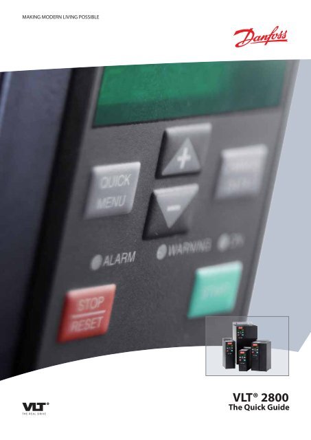
1.5.1 Control Unit<br />
On the front of the frequency converter there<br />
is a control panel divided into four sections.<br />
1. Six-digit LED display.<br />
2. Keys for changing parameters and<br />
shifting display function.<br />
3. Indicator lamps.<br />
4. Keys for local operation.<br />
LED indication<br />
Warning yellow<br />
Alarm red<br />
Trip locked yellow and red<br />
All displays of data are in the form of a six-digit LED display capable of showing one item of<br />
operating data continuously during normal operation. As a supplement to the display, there are<br />
three indicator lamps for indication of mains connection (ON), warning (WARNING) and alarm<br />
(ALARM). Most of the frequency converter's parameter Setups can be changed immediately via<br />
the control panel, unless this function has been programmed as Locked [1] via parameter 018<br />
Lock for data changes.<br />
1.5.2 Control Keys<br />
[QUICK MENU] allows access to the parameters used for the <strong>Quick</strong> menu.<br />
The[QUICK MENU] key is also used if a change to a parameter value is not to be implemented.<br />
See also [QUICK MENU] + [+].<br />
[CHANGE DATA] is used for changing a setting.<br />
If the display shows three dots at the right, the parameter value has more than three digits. In<br />
order to see the value, activate [CHANGE DATA]<br />
The [CHANGE DATA] key is also used for confirming a change of parameter settings.<br />
[+] / [-] are used for selecting parameters and for changing parameter values.<br />
These keys are also used in Display mode for selecting the display of an operating value.<br />
The [QUICK MENU] + [+] keys must be pressed at the same time to give access to all parameters.<br />
See Menu mode.<br />
[STOP/RESET] is used for stopping the connected motor or for resetting the frequency converter<br />
after a trip.<br />
Can be selected as Active [1] or Not active [0] via parameter 014 Local stop/reset. In Display<br />
mode, the display will flash if the stop function is activated.<br />
MG.28.M1.02 - <strong>VLT</strong> ® is a registered <strong>Danfoss</strong> trademark 17<br />
1
1<br />
1 <strong>Quick</strong> <strong>Guide</strong> <strong>VLT</strong> <strong>2800</strong> <strong>Quick</strong> <strong>Guide</strong><br />
NB!<br />
If the [STOP/RESET] key is set at Not active [0] in parameter 014 Local stop/reset,<br />
and there is no stop command via the digital inputs or serial communication,<br />
the motor can only be stopped by disconnecting the mains voltage to the frequency<br />
converter.<br />
[START] is used for starting the frequency converter. It is always active, but the [START] key<br />
cannot override a stop command.<br />
1.5.3 Manual initialisation<br />
Disconnect mains voltage. Hold the [QUICK MENU] + [+] + [CHANGE DATA] keys down while<br />
simultaneously reconnecting the mains voltage. Release the keys; the frequency converter has<br />
now been programmed for the factory setting.<br />
1.5.4 Display Readout States<br />
In normal operation, one item of operating data can be displayed continuously at the operator's<br />
own choice. By means of the [+/-] keys the following options can be selected in Display mode:<br />
1.5.5 Menu mode<br />
• Output frequency [Hz]<br />
• Output current [A]<br />
• Output voltage [V]<br />
• Intermediate circuit voltage [V]<br />
• Output power [kW]<br />
• Scaled output frequency fout x p008<br />
In order to enter the Menu mode [QUICK MENU] + [+] must be activated at the same time.<br />
In Menu mode, most of the frequency converter parameters can be changed. Scroll through the<br />
parameters using the [+/-] keys. While scrolling in the Menu mode proceeds, the parameter<br />
number will flash.<br />
1.5.6 <strong>Quick</strong> menu<br />
Using the [QUICK MENU] key, it is possible to access the 12 most important parameters of the<br />
frequency converter. After programming, the frequency converter is in most cases ready for operation.<br />
When the [QUICK MENU] key is activated in Display mode, the <strong>Quick</strong> menu starts. Scroll<br />
through the quick menu using the [+/-] keys and change the data values by first pressing<br />
[CHANGE DATA] and then changing the parameter value with the [+/-] keys.<br />
The <strong>Quick</strong> menu parameters are shown in section Parameter Lists.<br />
18 MG.28.M1.02 - <strong>VLT</strong> ® is a registered <strong>Danfoss</strong> trademark
<strong>VLT</strong> <strong>2800</strong> <strong>Quick</strong> <strong>Guide</strong> 1 <strong>Quick</strong> <strong>Guide</strong><br />
1.5.7 Hand Auto<br />
During normal operation the frequency converter is in Auto mode, where the reference signal is<br />
given externally, analog or digital via the control terminals. However, in Hand mode, it is possible<br />
to give the reference signal locally via the control panel.<br />
On the control terminals, the following control signals will remain active when Hand mode is activated:<br />
Hand Start (LCP2) <strong>Quick</strong> Stop Inverse Thermistor<br />
Off Stop (LCP2) Stop Inverse Precise Stop Inverse<br />
Auto Start (LCP2) Reversing Precise Stop/Start<br />
Reset DC Braking Inverse Jog<br />
Coasting Stop Inverse Setup Select LSB Stop Comm. Via Serial Comm.<br />
Reset and Coasting Stop Inverse Setup Select MSB<br />
Switching between Auto- and Hand mode:<br />
By activating the [Change Data] key in [Display Mode], the display will indicate the mode of the<br />
frequency converter.<br />
Scroll up/down in order to switch to Hand mode, the reference can be changed by using [+]/[-].<br />
NB!<br />
Please note, that parameter 020 may block the choice of mode.<br />
A change of parameter values is saved automatically after a mains failure.<br />
If the display shows three dots at the right, the parameter value has more than three digits. In<br />
order to see the value, activate [CHANGE DATA].<br />
Press [QUICK MENU]:<br />
Set the motor nameplate parameters<br />
Motor power [kW] Parameter 102<br />
Motor voltage [V] Parameter 103<br />
Motor frequency [Hz] Parameter 104<br />
Motor current [A] Parameter 105<br />
Rated motor speed Parameter 106<br />
Activate AMT<br />
Automatice motor tuning Parameter 107<br />
1. In parameter 107 Automatic motor tuning select data value [2]. “107” will now flash, and<br />
“2” will not flash.<br />
2. AMT is activated by pressing start. “107” will now flash and dashes will move from left<br />
to right in the data value field.<br />
3. When “107” appears once more with the data value [0], AMT is complete. Press [STOP/<br />
RESET] to save the motor data.<br />
4. “107” will then continue to flash with the data value [0]. You can now proceed.<br />
MG.28.M1.02 - <strong>VLT</strong> ® is a registered <strong>Danfoss</strong> trademark 19<br />
1
1<br />
1 <strong>Quick</strong> <strong>Guide</strong> <strong>VLT</strong> <strong>2800</strong> <strong>Quick</strong> <strong>Guide</strong><br />
Set reference range<br />
NB!<br />
<strong>VLT</strong> 2880-2882 do not have the AMT function.<br />
Min. reference, RefMIN Parameter 204<br />
Max. reference, RefMAX Parameter 205<br />
Set ramp time<br />
Ramp-up time [s] Parameter 207<br />
Ramp-down time [s] Parameter 208<br />
In parameter 002, Local/remote control, the frequency converter mode can be selected as Remote<br />
operation [0], i.e. via the control terminals, or Local [1], i.e. via the control unit.<br />
Set the control location to Local [1]<br />
Local/remote operation = Local [1], Par. 002<br />
Set the motor speed by adjusting the<br />
Local reference<br />
Local reference, Par. 003<br />
1.6 Motor Start<br />
Press [START] to start the motor. Set the motor speed by adjusting par. 003, Local reference.<br />
Check whether the direction of rotation of the motor shaft is clockwise. If not, exchange any two<br />
phases on the motor cable.<br />
Press [STOP/RESET] to stop the motor.<br />
Press [QUICK MENU] to return to display mode.<br />
[QUICK MENU] + [+] keys must be pressed simultaneously to give access to all parameters.<br />
20 MG.28.M1.02 - <strong>VLT</strong> ® is a registered <strong>Danfoss</strong> trademark
<strong>VLT</strong> <strong>2800</strong> <strong>Quick</strong> <strong>Guide</strong> 1 <strong>Quick</strong> <strong>Guide</strong><br />
1.7 Connection Examples<br />
More examples can be found in the Operating Instructions (MG.27.AX.YY).<br />
1.7.1 Start/Stop<br />
Start/stop using terminal 18 and coasting stop using terminal 27.<br />
Par. 302 Digital input = Start [7]<br />
Par. 304 Digital input = Coasting<br />
stop inverted [2]<br />
For Precise start/stop the following settings<br />
are made:<br />
1.8 Parameter List<br />
Par. 302 Digital input = Precise start/<br />
stop [27]<br />
Par. 304 Digital input = Coasting<br />
stop inverted [2]<br />
All parameters are listed in the following. For information on conversion index, data type and<br />
further descriptions, please see Operating Instructions (MG.27.AX.YY) or Design <strong>Guide</strong> (MG.<br />
27.EX.YY).<br />
For external communication, please see dedicated literature (see section Available Literature).<br />
NB!<br />
Use MCT-10 and USB to RS485 converter to change parameters.<br />
MG.28.M1.02 - <strong>VLT</strong> ® is a registered <strong>Danfoss</strong> trademark 21<br />
1
1<br />
1 <strong>Quick</strong> <strong>Guide</strong> <strong>VLT</strong> <strong>2800</strong> <strong>Quick</strong> <strong>Guide</strong><br />
[2] Speed control, closed loop<br />
[3] Process control, closed loop<br />
101 Torque Characteristic<br />
*[1] Constant torque<br />
[2] Variable torque low<br />
[3] Variable torque medium<br />
[4] Variable torque high<br />
[5] Variable torque low with CT start<br />
[6] Variable torque medium with CT start<br />
[7] Variable torque high with CT start<br />
[8] Special motor mode<br />
102 Motor Power PM,N<br />
0.25 - 22 kW, *Dep. on unit<br />
103 Motor Voltage UM,N<br />
For 200 V units: 50 - 999 V, *230 V<br />
For 400 V units: 50 - 999 V, *400V<br />
104 Motor Frequency fM,N<br />
24 - 1000 Hz, *50 Hz<br />
105 Motor Current IM,N<br />
0.01 - IMAX, Dep. on motor<br />
106 Rated Motor Speed<br />
100 - fM,N x 60 (max. 60000 rpm), Dep. on par. 104<br />
107 Automatic Motor Tuning, AMT<br />
*[0] Optimisation off<br />
[1] Optimisation on<br />
108 Stator Resistance RS<br />
0.000 - x.xxx Ω, *Dep. on motor<br />
109 Stator Resistance XS<br />
0.00 - x.xx Ω, *Dep. on motor<br />
117 Resonance Damping<br />
OFF - 100%<br />
*OFF%<br />
119 High Start Torque<br />
0.0 - 0.5 s * 0.0 s<br />
120 Start Delay<br />
0.0 - 10.0 s * 0.0 s<br />
Parameter Overwiev<br />
008 Display Scaling of Output Frequency 013 Local Control<br />
0.01 - 100.00, *1.00<br />
[0] Local not active<br />
009 Large Diplay Readout<br />
[1] Local control and open loop without slip com-<br />
[0] No readout<br />
pensation<br />
[1] Resulting reference [%]<br />
[2] Remote-operated control and open loop without<br />
[2] Resulting reference [unit]<br />
slip compensation<br />
[3] Feedback [unit]<br />
[3] Local control as par. 100<br />
*[4] Frequency [Hz]<br />
*[4] Remote-operated contorl as par. 100014 Lo-<br />
[5] Output frequency x scaling<br />
cal stop<br />
[6] Motor current [A]<br />
[0] Not active<br />
[7] Torque [%]<br />
*[1] Active<br />
[8] Power [kW]<br />
015 Local Jog<br />
[9] Power [HP]<br />
*[0] Not active<br />
[11] Motor voltage [V]<br />
[1] Active<br />
[12] DC link voltage [V]<br />
016 Local Reversing<br />
[13] Thermal load motor [%]<br />
*[0] Not active<br />
[14] Thermal load [%]<br />
[1] Active<br />
[15] Running hours [Hours]<br />
017 Local reset of Trip<br />
[16] Digital input [Bin]<br />
[0] Not active<br />
[17] Analog input 53 [V]<br />
*[1] Active<br />
[19] Analog input 60 [mA]<br />
018 Lock for Data Changes<br />
[20] Pulse reference [Hz]<br />
*[0] Not locked<br />
[21] External reference [%]<br />
[1] Locked<br />
[22] Status word [Hex]<br />
019 Operating Mode at Power-up, Local Op-<br />
[25] Heatsink temperature [°C]<br />
eration<br />
[26] Alarm word [Hex]<br />
[0] Auto re-start, use saved reference<br />
[27] Control word [Hex]<br />
*[1] Forced stop, use saved reference<br />
[28] Warning word [Hex]<br />
[2] Forced stop, set ref. to 0<br />
[29] Extended status word [Hex]<br />
020 Hand Operation<br />
[30] Communication option card warning<br />
*[0] Not active<br />
[31] Pulse count<br />
[1] Active<br />
010 Small Display Line 1.1<br />
024 Userdefined <strong>Quick</strong> Menu<br />
See par. 009.<br />
*[0] Not active<br />
*[17] Analog input 53<br />
[1] Active<br />
011 Small Display Readout 1.2<br />
025 <strong>Quick</strong> Menu Set-up<br />
See par. 009.<br />
Value 0 - 999, *000<br />
*[6] Motor Current [A]<br />
Load and Motor<br />
012 Small Display Readout 1.3<br />
100 Configuration<br />
*See par. 009.<br />
*[0] Speed control, open loop<br />
*[3] Feedback [unit]<br />
0-XX Operation/Display<br />
0-01 Language<br />
*[0] English<br />
[1] German<br />
[2] French<br />
[3] Danish<br />
[4] Spanish<br />
[5] Italian002 Local/Remote Operation<br />
*[0] Remote operation<br />
[1] Local operation<br />
003 Local Reference<br />
If par. 013 = [1] or [2]: 0 - fMAX, *50 Hz<br />
If par. 013 = [3] or [4]: RefMIN - RefMAX, *0.0<br />
004 Active Set-up<br />
[0] Factory Set-up<br />
*[1] Set-up 1<br />
[2] Set-up 2<br />
[3] Set-up 3<br />
[4] Set-up 4<br />
[5] Multi Set-up<br />
005 Programming Set-up<br />
[0] Factory Set-up<br />
*[1] Set-up 1<br />
[2] Set-up 2<br />
[3] Set-up 3<br />
[4] Set-up 4<br />
*[5] Active Set-up<br />
0-06 Set-up Copying<br />
*[0] No copying<br />
[1] Copy to Set-up 1 from #<br />
[2] Copy to Set-up 2 from #<br />
[3] Copy to Set-up 3 from #<br />
[4] Copy to Set-up 4 from #<br />
[5] Copy to all set-ups from #<br />
007 LCP Copy<br />
*[0] No copying<br />
[1] Upload all parameters<br />
[2] Download all parameters<br />
[3] Download size-independent parameters<br />
22 MG.28.M1.02 - <strong>VLT</strong> ® is a registered <strong>Danfoss</strong> trademark
<strong>VLT</strong> <strong>2800</strong> <strong>Quick</strong> <strong>Guide</strong> 1 <strong>Quick</strong> <strong>Guide</strong><br />
221 Current Limit, ILIM<br />
0 - xxx.x% of par. 105, * 160%<br />
223 Warning, Low Current, ILOW<br />
0.0 - par. 224 Warning: High Current, IHIGH, * 0.0 A<br />
224 Warning: High Current, IHIGH<br />
0 - IMAX, * IMAX<br />
225 Warning: Low Frequency, fLOW<br />
0.0 - par. 226 Warn.: High frequency, f<br />
HIGH, *0.0 Hz<br />
226 Warning: High Frequency fHIGH<br />
If par. 200 = [0]/[1]. Par. 225 fLOW - 132 Hz, * 132.0<br />
Hz<br />
If par. 200 [2]/[3]. Par 225 fLOW - 1000 Hz, * 132.0<br />
Hz<br />
227 Warning: Low Feedback, FBLOW<br />
0.0 - 400.0 Hz * 0.0 Hz-100,000.000 - par. 228<br />
Warn.: FBHIGH, * -4000.000<br />
228 Warning: High Feedback, FBHIGH<br />
Par. 227 Warn.: FBLOW - 100,000.000, * 4000.000<br />
229 Frequency Bypass, Bandwidth<br />
0 (OFF) - 100 Hz, * 0 Hz<br />
230 - 231 Frequency Bypass 1 - 2<br />
0 - 100 Hz, *0.0 Hz<br />
Inputs and Outputs<br />
302 Terminal 18 Digital Input<br />
[0] No function<br />
[1] Reset<br />
[2] Coasting stop inverse<br />
[3] Reset and coasting inverse<br />
[4] <strong>Quick</strong>-stop inverse<br />
[5] DC braking inverse<br />
[6] Stop inverse<br />
*[7] Start<br />
[8] Pulse start<br />
[9] Reversing<br />
[10] Reversing<br />
[11] Start Clockwise<br />
[12] Start counterclockwise<br />
[13] Jog<br />
[14] Freeze reference<br />
[15] Freeze output frequency<br />
204 Minimum Reference, RefMIN<br />
Par. 100 [0]. -100,000.000 - par. 205 RefMAX, *0.000<br />
Hz<br />
Par. 100 [1]/[3], -par. 414 Minimum feedback - par.<br />
205 RefMAX, *0.000 rpm/par. 416<br />
205 maximum Reference, RefMAX<br />
Par. 100 [0]. Par. 204 RefMIN - 1000.000 Hz, *50.000<br />
Hz<br />
Par. 100 [1]/[3]. Par. 204 RefMIN - Par. 415 Max<br />
Feedback, *50.000 rpm/par. 416<br />
206 Ramp Type<br />
*[0] Linear<br />
[1] Sin shaped<br />
[2] Sin2 207 Ramp-up Time 1<br />
0.02 - 3600.00 s, * 3.00 s (<strong>VLT</strong> 2803 - 2875), *<br />
10.00 (2880 - 2882)<br />
208 Ramp-down Time 1<br />
0.02 - 3600.00 s, * 3.00 s (<strong>VLT</strong> 2803 - 2875), *<br />
10.00 (2880 - 2882)<br />
209 Ramp-up Time 2<br />
0.02 - 3600.00 s, * 3.00 s (<strong>VLT</strong> 2803 - 2875), *<br />
10.00 (2880 - 2882)<br />
210 Ramp-down Time 2<br />
0.02 - 3600.00 s, * 3.00 s (<strong>VLT</strong> 2803 - 2875), *<br />
10.00 (2880 - 2882)<br />
211 Jog Ramp Time<br />
0.02 - 3600.00 s, * 3.00 s (<strong>VLT</strong> 2803 - 2875), *<br />
10.00 (2880 - 2882)<br />
212 <strong>Quick</strong>-stop Ramp-down Time<br />
0.02 - 3600.00 s, * 3.00 s (<strong>VLT</strong> 2803 - 2875), *<br />
10.00 (2880 - 2882)<br />
213 Jog Frequency<br />
0.0 - Par. 202 Output Frequency High Limit, fMAX<br />
214 Reference Function<br />
*[0] Sum<br />
[1] Relative<br />
[2] External/preset<br />
215-218 Preset reference 1-4<br />
0.0 - 400.0 Hz * 0.0 Hz-100.00% - +100.00%, *<br />
0.00%<br />
219 Catch Up/Slow Down Reference<br />
0.00 - 100% of the given reference, * 0.00%<br />
136 Slip Compensation<br />
0 - 150 % * 100 %-500 . +500% of rated slip compensation,<br />
*100%<br />
137 DC Hold Voltage<br />
0 - 100% if nax. DC hold voltage, *0%<br />
138 Brake Cut Out Value<br />
0.5 - 132.0/1000.0 Hz, *3.0 Hz<br />
139 Brake Cut In Frequency<br />
0.5 - 132.0/1000.0 Hz, *3.0 Hz<br />
140 Current, Minimum Value<br />
0% - 100% of inverter output current<br />
142 Leakage Reactance XL<br />
0.000 - xxx.xxx Ω, *Dep- on motor<br />
143 Internal Fan Control<br />
*[0] Automatic<br />
[1] Always switched on<br />
[2] Always switched off<br />
144 Gain AC Brake<br />
1.00 - 1.50, *1.30<br />
146 Reset Voltage Vector<br />
*[0] Off<br />
[1] Reset<br />
References and Limits200 Output Frequency<br />
Range<br />
*[0] Only clockwise, 0 - 132 Hz<br />
[1] Both directions, 0 - 132 Hz<br />
[2] Counterclockwise only, 0 - 132 Hz<br />
[4] Both directions, 0 - 1000 Hz<br />
[5] Counterclokcwise only, 0 - 1000 Hz<br />
201 Output Frequency Low Limit, fMIN<br />
0.0 - fMAX, *0.0 Hz<br />
202 Output Frequency High Limit, FMAX<br />
fMIN - 132/1000 Hz (par. 200 Output frequency<br />
range, 132 Hz<br />
203 Reference Range<br />
[0] Min. reference - Max. reference<br />
[1] Analog Input 53 -Max. reference - +Max. reference<br />
121 Start Function<br />
[0] DC hold during start delay time<br />
[1] DC brake during start delay time<br />
*[2] Coasting during start delay time<br />
[3] Start frequency/voltage clockwise<br />
[4] Start frequency/voltage in reference direction<br />
122 Function at Stop<br />
*[0] Coasting<br />
[1] DC hold<br />
123 Min. Frequency for Activation of Function<br />
at Stop<br />
0.1 - 10 Hz, *0.1 Hz<br />
126 DC Brake Time<br />
0 - 60 s, *10 s<br />
127 DC brake cut-in Frequency<br />
0.0 (OFF) - Par. 202, *OFF<br />
128 Thermal Motor Protection<br />
*[0] No protection<br />
[1] Thermistor warning<br />
[2] Thermistor trip<br />
[3] ETR warning 1<br />
[4] ETR trip 1<br />
[5] ETR warning 2<br />
[6] ETR trip 2<br />
[7] ETR warning 3<br />
[8] ETR trip 3<br />
[9] ETR warning 4<br />
[10] ETR trip 4<br />
130 Start Frequency<br />
0.0 - 10.0 Hz, *0.0 Hz<br />
131 Initial Voltage<br />
0.0 - 200.0 V, *0.0 V<br />
132 DC Brake Voltage<br />
0 - 100% of max. DC brake voltage, *0%<br />
133 Start Voltage<br />
0.00 - 100.00 V, *Dep. on unit<br />
134 Load Compensation<br />
0.0 - 300.0%, 100,0%<br />
135 U/f Ratio<br />
0.00 - 20.00 at Hz, *Dep. on unit<br />
MG.28.M1.02 - <strong>VLT</strong> ® is a registered <strong>Danfoss</strong> trademark 23<br />
1
1<br />
1 <strong>Quick</strong> <strong>Guide</strong> <strong>VLT</strong> <strong>2800</strong> <strong>Quick</strong> <strong>Guide</strong><br />
[14] Output current lower than IHIGH par. 224<br />
[15] Feedback higher than FBLOW<br />
[16] Feedback lower than FBHIGH par. 228<br />
[17] Relay 123<br />
[18] Reversing<br />
[19] Thermal warning<br />
[20] Local operation<br />
[22] Out of frequency range par. 225/226<br />
[23] Out of current range<br />
[24] Out of feedback range<br />
[24] Mechanical brake control<br />
[25] Control word bit 11<br />
327 Pulse reference/feedback<br />
150 - 67600 Hz, * 5000 Hz<br />
328 Maximum Pulse 29<br />
150 - 67600 Hz, * 5000 Hz<br />
341 Digital/Pulse Output Terminal 46<br />
[0] Unit ready<br />
Par. [0] - [20], see par. 323<br />
[21] Pulse reference<br />
Par. [22] - [25], see par. 323<br />
[26] Pulse feedback<br />
[27] Output frequency<br />
[28] Pulse current<br />
[29] Pulse power<br />
[30] Pulse temperature<br />
342 Terminal 46, max. Pulse Scaling<br />
150 - 10000 Hz, * 5000 Hz<br />
343 Precise Stop Function<br />
*[0] Precise ramp stop<br />
[1] Counter stop with reset<br />
[2] Counter stop without reset<br />
[3] Speed-compensated counter stop<br />
[4] Speed-compensated stop with reset<br />
[5] Speed-compensated stop without reset<br />
344 Counter Value<br />
0 - 999999, * 100000 pulses<br />
349 Speed Comp Delay<br />
0 ms - 100 ms, * 10 ms<br />
Special Functions<br />
400 Brake Function<br />
[0] OFF<br />
[1] Resistor brake<br />
[4] AC brake<br />
[5] Load sharing<br />
314 Terminal 60 Analog Input Current<br />
[0] No function<br />
[1] Reference<br />
*[2] Feedback<br />
[10] Wobble<br />
315 Terminal 60 Min. Scaling<br />
0.0 - 20.0 mA, * 4.0 mA<br />
316 Terminal 60 Max. Scaling<br />
0.0 - 20.0 mA, * 20.0 mA<br />
317 Time Out<br />
1 - 99 s * 10 s<br />
318<br />
*[0] No operation<br />
[1] Freeze output frequency<br />
[2] Stop<br />
[3] Jog<br />
[4] Max speed<br />
[5] Stop and trip<br />
319 Analog output terminal 42<br />
[0] No function<br />
[1] External reference min. - max. 0 - 20 mA<br />
[2] External reference min. - max. 4- 20 mA<br />
[3] Feedback min. - max. 0-20 mA<br />
[4] Feedback min. - max. 4- 20 mA<br />
[5] Output frequency 0 - max 0-20 mA<br />
[6] Output frequency 0 - max 4-20 mA<br />
*[7] Output current 0 - IINV 0-20 mA<br />
[8] Output current 0 - IINV 4-20 mA<br />
[9] Output power 0-PM,N 0-20 mA<br />
[10] Output power 0-PM,N 4-20 mA<br />
[11] Inverter temperature 20-100 °C 0-20 mA<br />
[12] Inverter temperature 20-100 °C 4-20 mA<br />
323 Relay Output 1-3<br />
[0] No function<br />
*[1] Unit ready<br />
[2] Enable/no warning<br />
[3] Running<br />
[4] Running in reference, no warning<br />
[5] Running, no warning<br />
[6] Running in reference range, no warnings<br />
[7] Ready - mains voltage within range<br />
[8] Alarm or warning<br />
[9] Current higher than current limit<br />
[10] Alarm<br />
[11] Output frequency higher than fLOW<br />
[12] Output frequency lower than fHIGH<br />
[13] Output current higher than ILOW<br />
[27] Precise Start Stop<br />
[31] Selection of Set-up, LSB<br />
[32] Selection of Set-up, MSB<br />
[33] Reset and start<br />
[34 Pulse counter start<br />
305 Terminal 29 Digital Input<br />
See par. 305 * [13] Jog<br />
307Terminal 33 Digital Input<br />
*[0] No function<br />
[1] Reset<br />
[2] Coasting stop inverse<br />
[3] Reset and coasting inverse<br />
[4] <strong>Quick</strong>-stop inverse<br />
[5] DC braking inverse<br />
[6] Stop inverse<br />
[7] Start<br />
[8] Pulse start<br />
[9] Reversing<br />
[10] Reversing<br />
[11] Start Clockwise<br />
[12] Start counterclockwise<br />
[13] Jog<br />
[14] Freeze reference<br />
[15] Freeze output frequency<br />
[16] Speed up<br />
[17] Speed down<br />
[19] Catch up<br />
[20] Slow down<br />
[21] Ramp 2<br />
[22] Preset ref, LSB<br />
[23] Preset ref, MSB<br />
[24] Preset reference on<br />
[28] Pulse reference<br />
[29] Pulse feedback<br />
[30] Pulse input<br />
[31] Selection of Set-up, LSB<br />
[32] Selection of Set-up, MSB<br />
[33] Reset and start<br />
308 Terminal 53, Analog Input Voltage<br />
[0] No function<br />
*[1] Reference<br />
[2] Feedback<br />
[3] Wobble 309 Terminal 53 Min. Scaling<br />
0.0 - 10.0 V, * 0.0 V<br />
310 Terminal 53 Max. Scaling<br />
0.0 - 10.0 V, * 10.0 V<br />
[16] Speed up<br />
[17] Speed down<br />
[19] Catch up<br />
[20] Slow down<br />
[21] Ramp 2<br />
[22] Preset ref, LSB<br />
[23] Preset ref, MSB<br />
[24] Preset reference on<br />
[25] Thermistor<br />
[26] Precise stop<br />
[27] Precise Start Stop<br />
[31] Selection of Set-up, LSB<br />
[32] Selection of Set-up, MSB<br />
[33] Reset and start<br />
[34 Pulse counter start<br />
303 Terminal 19 Digital Input<br />
See par. 302 * [9] Reversing<br />
304 Terminal 27 Digital Input<br />
[0] No function<br />
[1] Reset<br />
[2] Coasting stop inverse<br />
*[3] Reset and coasting inverse<br />
[4] <strong>Quick</strong>-stop inverse<br />
[5] DC braking inverse<br />
[6] Stop inverse<br />
[7] Start<br />
[8] Pulse start<br />
[9] Reversing<br />
[10] Reversing<br />
[11] Start Clockwise<br />
[12] Start counterclockwise<br />
[13] Jog<br />
[14] Freeze reference<br />
[15] Freeze output frequency<br />
[16] Speed up<br />
[17] Speed down<br />
[19] Catch up<br />
[20] Slow down<br />
[21] Ramp 2<br />
[22] Preset ref, LSB<br />
[23] Preset ref, MSB<br />
[24] Preset reference on<br />
[25] Thermistor<br />
[26] Precise stop<br />
24 MG.28.M1.02 - <strong>VLT</strong> ® is a registered <strong>Danfoss</strong> trademark
<strong>VLT</strong> <strong>2800</strong> <strong>Quick</strong> <strong>Guide</strong> 1 <strong>Quick</strong> <strong>Guide</strong><br />
456 Brake Voltage Reduce<br />
0 - 25 V if 200 V, * 0<br />
0 - 50 V if 400 V, * 0<br />
461 Feedback Conversion<br />
*[0] Linear<br />
[1] Square root<br />
462 Enhanced Sleep Mode Timer<br />
Value 0 - 9999 s, * 0 = OFF<br />
463 Boost Setpoint<br />
1 - 200%, * 100% of setpoint<br />
464 Wakeup Pressure<br />
Par. 204, RefMIN - par. 215-218 setpoint, * 0<br />
465 Minimum Pump Frequency<br />
Value par. 201, fMIN - par. 202 fMAX (Hz), * 20<br />
466 Maximum Pump Frequency<br />
Value par. 201, fMIN - par. 202 fMAX (Hz), * 50<br />
467 Minimum Pump Power<br />
0 - 500.000 W, * 0<br />
468 Maximum Pump Power<br />
0 - 500.000 W, * 0<br />
469 No Flow Power Compensation<br />
0.01 - 2, * 1.2<br />
470 Dry Run Time Out<br />
5 - 30 s, * 31 = OFF<br />
471 Dry Run Interlock Timer<br />
0.5 - 60 min., * 30 min.<br />
484 Initial Ramp<br />
OFF/000.1 s - 360.0 s, * OFF<br />
485 Fill Rate<br />
OFF/000000.001 - 999999.999 (units/s), * OFF<br />
486 Filled Setpoint<br />
Par. 414 - par. 205, * par. 414<br />
423 U1 Voltage0.0 - 999.0 V, * par. 103<br />
424 F1 Frequency<br />
0.0 - par. 426, F2 frequency, * Par. 104<br />
425 U2 Voltage<br />
0.0 - 999.0 V, * par. 103<br />
426 F2 Frequency<br />
Par. 424, F1 frequency - Par. 428, F3 frequency, *<br />
par. 104<br />
427 U3 Voltage<br />
0.0 - 999.0 V, * par. 103<br />
428 F3 Frequency<br />
Par. 426, F2 frequency - 1000 Hz, * par. 104<br />
437 Process PID Normal/Inverse Control<br />
*[0] Normal<br />
[1] Inverse<br />
438 Process PID Anti Windup<br />
[0] Not active<br />
[1] Active<br />
Process PID Start Frequency<br />
fMIN - fMAX (par. 201 - par. 202), * par. 201<br />
440 Process PID Proportional Gain<br />
0.0 - 10.00, * 0.01<br />
441 Process PID Integration Time<br />
0.00 (OFF) - 10.00 s, * OFF<br />
442 Process PID Differentiation Time<br />
0.00 (OFF) - 10.00 s, * 0.00 s<br />
443 Process PID Diff. Gain Limit<br />
5.0 - 50.0, * 5.0<br />
444 Process PID Lowpass Filter Time<br />
0.02 - 10.00, * 0.02<br />
445 Flying Start<br />
*[0] OFF<br />
[1] OK - same direction<br />
[2] OK - both directions<br />
[2] DC brake and start<br />
451 Speed PID Feedforward Factor<br />
0 - 500 %, * 100 %<br />
452 Controller Range<br />
0 - 200 %, * 10 %<br />
[13] m3 /s<br />
[14] l/min<br />
[15] m3 /min<br />
[16] l/h<br />
[17] m3 /h<br />
[18] Kg/s<br />
[19] Kg/min<br />
[20] Kg/h<br />
[21] T/min<br />
[22] T/h<br />
[23] Metres<br />
[24] Nm<br />
[25] m/s<br />
[26] m/min<br />
[27] ° F<br />
[28] In wg<br />
[29] Gal/s<br />
[30] Ft3 /s<br />
[31] Gal/min[32] Ft3 /min<br />
[33] Gal/h<br />
[34] Ft3 /h<br />
[35] Lb/s<br />
[36] Lb/min<br />
[37] Lb/h<br />
[38] Lb ft<br />
[39] Ft/s<br />
[40] Ft/min<br />
417 Speed PID Proportional Gain<br />
0.000 (OFF) - 1.000, * 0.010<br />
418 Speed PID Integral Time<br />
20.00 - 999.99 ms (1000 - OFF), * 100 ms<br />
419 Speed PID Differential Time<br />
0.00 (OFF) - 200.00 ms, * 20.00 ms<br />
420 Speed PID D-Gain Limit<br />
5.0 - 50.0, * 5.0<br />
421 Speed PID Lowpass Filter Time<br />
20 - 500 ms, * 100 ms<br />
405 Reset Function<br />
*[0] Manual reset<br />
[1] Automatic reset x 1<br />
[3] Automatic reset x 3<br />
[10] Automatic reset x 10<br />
[11] Reset at power-up<br />
406 Automatic Restart Time<br />
0 - 10 s, * 5 s<br />
409 Trip Delay Overcurrent, ILIM<br />
0 - 60 s (61 = OFF), * OFF<br />
411 Switching Frequency<br />
3000 - 14000 Hz (<strong>VLT</strong> 2803 - 2875), * 4500 Hz<br />
3000 - 10000 Hz (<strong>VLT</strong> 2880 - 2882), * 4500 Hz<br />
412 Variable Switching Frequency<br />
*[2] Without LC-filter<br />
[3] LC-filter connected<br />
413 Overmodulation Function<br />
[0] OFF<br />
*[1] ON<br />
414 Minimum Feedback, FBMIN<br />
-100,000.000 - par. 415, FBMAX, * 0.000<br />
415 Maximum Feedback, FBMAX<br />
FBMIN - 100,000.000, * 1500.000<br />
416 Process Units<br />
*[0] No unit<br />
[1] %<br />
[2] ppm<br />
[3] rpm<br />
[4] bar<br />
[5] Cycles/min<br />
[6] Pulses/s<br />
[7] Units/s<br />
[8] Units/min<br />
[9] Units/h<br />
[10] ° C<br />
[11] Pa<br />
[12] I/s<br />
MG.28.M1.02 - <strong>VLT</strong> ® is a registered <strong>Danfoss</strong> trademark 25<br />
1
1<br />
1 <strong>Quick</strong> <strong>Guide</strong> <strong>VLT</strong> <strong>2800</strong> <strong>Quick</strong> <strong>Guide</strong><br />
1.9.1 Warnings/alarm messages<br />
No. Description W A T Cause of Problem<br />
2 Live zero error (LIVE ZERO X X X Voltage or current signal on terminals 53 or 60<br />
ERROR)<br />
is below 50% of preset value.<br />
4 Mains phase loss (MAINS<br />
PHASE LOSS)<br />
X X X No phase on mains supply side.<br />
5 Voltage warning high (DC X The intermediate circuit voltage exceeds the lim-<br />
LINK VOLTAGE HIGH)<br />
it set.<br />
6 Voltage warning low (DC X The intermediate circuit voltage is lower the limit<br />
LINK VOLTAGE LOW)<br />
set.<br />
7 Overvoltage (DC LINK<br />
OVERVOLT)<br />
X X X The intermediate voltage exceeds the limit set.<br />
8 Undervoltage (DC LINK UN- X X X The intermediate voltage is lower than the limit<br />
DERVOLT)<br />
set.<br />
9 Inverter overload (INVER- X X The frequency converter is close to tripping due<br />
TER TIME)<br />
to overload.<br />
10 Motor overloaded ( MOTOR,<br />
TIME)<br />
X X The motor is too hot due to overload.<br />
11 Motor thermistor (MOTOR X X Either the motor is too hot or the thermistor has<br />
THERMISTOR)<br />
been disconnected.<br />
12 Current limit (CURRENT<br />
LIMIT)<br />
X X Output current is higher than set in par. 221.<br />
13 Overcurrent (OVERCUR-<br />
RENT)<br />
X X X The peak current limit has been exceeded.<br />
14 Earth fault (EARTH FAULT) X X Discharge from output phases to earth.<br />
15 Switch mode fault (SWITCH<br />
MODE FAULT)<br />
X X Fault in switch mode power supply.<br />
16 Short-circuit (CURR. SHORT X X Short-circuit on the motor terminals or in the<br />
CIRCUIT)<br />
motor.<br />
17 Serial communication time- X X No serial communication to the frequency conout<br />
(STD BUS TIMEOUT)<br />
verter.<br />
18 HPFB bus timeout (HPFB X X No serial communication to the communication<br />
TIMEOUT)<br />
option card.<br />
33 Out of frequency range X Output frequency has reached the limit set in<br />
(OUT FREQ RNG/ROT LIM) either par. 201 or par. 202.<br />
34 HPFB communication fault X X Fault only occurs in fieldbus versions. Please see<br />
(PROFIBUS OPT. FAULT)<br />
par. 953 in fieldbus literature.<br />
35 Inrush fault (INRUSH X X Connected to mains too many times within 1 mi-<br />
FAULT)<br />
nute.<br />
36 Overtemperature (OVER-<br />
TEMPERATURE)<br />
X X The upper temperature limit has been exceeded.<br />
37-45 Internal fault (INTERNAL<br />
FAULT)<br />
X X Please contact <strong>Danfoss</strong>.<br />
W: Warning, A: Alarm, T: Trip locked<br />
26 MG.28.M1.02 - <strong>VLT</strong> ® is a registered <strong>Danfoss</strong> trademark
<strong>VLT</strong> <strong>2800</strong> <strong>Quick</strong> <strong>Guide</strong> 1 <strong>Quick</strong> <strong>Guide</strong><br />
No. Description W A T Cause of Problem<br />
50 AMT not possible X Either RS value is outside permitted limits, or<br />
motor current is too low on at least one phase,<br />
or the motor is too small for AMA.<br />
51 AMT fault re. nameplate data<br />
(AMT TYPE.DATA FAULT)<br />
X Inconsistency between registered motor data.<br />
54 AMT wrong motor (AMT<br />
WRONG MOTOR)<br />
X AMA has detected a missing motor phase.<br />
55 AMT timeout (AMT TIME- X Calculations are taking too long, probably<br />
OUT)<br />
caused by noise on motor cables.<br />
56 AMT warning during AMT<br />
(AMT WARN. DURING AMT)<br />
X Warning is given while AMA is performed.<br />
99 Locked (LOCKED) X See par. 018.<br />
W: Warning, A: Alarm, T: Trip locked<br />
A warning or an alarm will appear in the display as a numerical code Err. xx. A warning will be<br />
shown on the display until the fault has been corrected, while an alarm will continue to flash until<br />
the [STOP/RESET] key is activated.The table shows the various warnings and alarms, and whether<br />
the fault locks the frequency converter. After a Trip locked the mains supply is cut off and the<br />
fault is corrected. The mains supply is reconnected and the frequency converter is reset. The<br />
frequency converter is now ready. A Trip can be reset manually in three ways:<br />
1. Via the operating key [STOP/RESET].<br />
2. Via a digital input.<br />
3. Via serial communication.<br />
It is also possible to choose an automatic reset in parameter 405 Reset function. When a cross<br />
appears in both warning and alarm, this can mean that a warning comes before an alarm. It can<br />
also mean that it is possible for the user to programme whether a warning or an alarm will appear<br />
for a given fault. For example, this is possible in parameter 128 Motor thermal protection. After a<br />
trip the motor will coast, and alarm and warning will blink on the frequency converter, but if the<br />
fault disappears only the alarm will blink. After a reset the frequency converter will be ready to<br />
start operation again.<br />
MG.28.M1.02 - <strong>VLT</strong> ® is a registered <strong>Danfoss</strong> trademark 27<br />
1
1<br />
1 <strong>Quick</strong> <strong>Guide</strong> <strong>VLT</strong> <strong>2800</strong> <strong>Quick</strong> <strong>Guide</strong><br />
1.10 Specifications<br />
1.10.1 Mains Suply 200 - 400 V<br />
According to . international<br />
Type 2803 2805 2807 2811 2815 2822 2822 2840 2840<br />
standards<br />
PD2 PD2<br />
Output current IINV. [A] 2.2 3.2 4.2 6.0 6.8 9.6 9.6 16 16<br />
(3 x 200-240V) IMAX (60s) [A] 3.5 5.1 6.7 9.6 10.8 15.3 10.6 25.6 17.6<br />
Output power<br />
(230 V)<br />
SINV. [KVA] 0.9 1.3 1.7 2.4 2.7 3.8 3.8 6.4 6.4<br />
Typical shaft output<br />
PM,N [kW] 0.37 0.55 0.75 1.1 1.5 2.2 2.2 3.7 3.7<br />
Typical shaft output<br />
PM,N [HP] 0.5 0.75 1.0 1.5 2.0 3.0 3.0 5.0 5.0<br />
Max. cable cross<br />
section, motor<br />
[mm2 /AWG] 4/10 4/10 4/10 4/10 4/10 4/10 4/10 4/10 16/6<br />
Input current IL,N [A] 5.9 8.3 10.6 14.5 15.2 - 22.0 - 31.0<br />
(1 x 220-240 V) IL,MAX (60s)<br />
[A]<br />
9.4 13.3 16.7 23.2 24.3 - 24.3 - 34.5<br />
Input current IL,N [A] 2.9 4.0 5.1 7.0 7.6 8.8 8.8 14.7 14.7<br />
(3 x 200-240 V) IL,MAX (60s)<br />
[A]<br />
4.6 6.4 8.2 11.2 12.2 14.1 9.7 23.5 16.2<br />
Max. cable cross<br />
section, power<br />
[mm2 /AWG] 4/10 4/10 4/10 4/10 4/10 4/10 4/10 4/10 16/6<br />
Max. pre-fuses IEC/UL [A] 20/2 20/2 20/2 20/2 20/2 20/2 35/3 25/2 50/5<br />
0 0 0 0 0 0 5 5 0<br />
Efficiency [%] 95 95 95 95 95 95 95 95 95<br />
Power loss at<br />
100% load<br />
[W] 24 35 48 69 94 125 125 231 231<br />
Weight [kg] 2.0 2.0 2.0 2.0 2.0 3,7 6.0 6.0 18.5<br />
0<br />
Enclosure type IP 20 IP 20 IP 20 IP 20 IP 20 IP 20 IP 20 IP 20 IP<br />
20/<br />
NEM<br />
A 1<br />
1.10.2 Mains Supply 380 - 480 V<br />
According to international<br />
standards<br />
Type 2805 2807 2811 2815 2822 2830<br />
Output current IINV. [A] 1.7 2.1 3.0 3.7 5.2 7.0<br />
(3 x 380-480V) IMAX (60s) [A] 2.7 3.3 4.8 5.9 8.3 11.2<br />
Output power (400<br />
V)<br />
SINV. [KVA] 1.1 1.7 2.0 2.6 3.6 4.8<br />
Typical shaft output<br />
PM,N [kW] 0.55 0.75 1.1 1.5 2.2 3.0<br />
Typical shaft output<br />
PM,N [HP] 0.75 1.0 1.5 2.0 3.0 4.0<br />
Max. cable cross<br />
section, motor<br />
[mm2 /AWG] 4/10 4/10 4/10 4/10 4/10 4/10<br />
Input current IL,N [A] 1.6 1.9 2.6 3.2 4.7 6.1<br />
(3 x 380-480 V) IL,MAX(60s)[A] 2.6 3.0 4.2 5.1 7.5 9.8<br />
Max. cable cross<br />
section, power<br />
[mm2 /AWG] 4/10 4/10 4/10 4/10 4/10 4/10<br />
Max. pre-fuses IEC/UL [A] 20/20 20/20 20/20 20/20 20/20 20/20<br />
Efficiency [%] 96 96 96 96 96 96<br />
Power loss at 100%<br />
load<br />
[W] 28 38 55 75 110 150<br />
Weight [kg] 2.1 2.1 2.1 2.1 3.7 3.7<br />
Enclosure type IP 20 IP 20 IP 20 IP 20 IP 20 IP 20<br />
28 MG.28.M1.02 - <strong>VLT</strong> ® is a registered <strong>Danfoss</strong> trademark
<strong>VLT</strong> <strong>2800</strong> <strong>Quick</strong> <strong>Guide</strong> 1 <strong>Quick</strong> <strong>Guide</strong><br />
According to international<br />
standards<br />
Type 2840 2855 2875 2880 2881 2882<br />
Output current IINV. [A] 9.1 12 16 24 32.0 37.5<br />
(3 x 380-480V) IMAX (60s) [A] 14.5 19.2 25.6 38.4 51.2 60.0<br />
Output power (400<br />
V)<br />
SINV. [KVA] 6.3 8.3 11.1 16.6 22.2 26.0<br />
Typical shaft output<br />
PM,N [kW] 4.0 5.5 7.5 11.0 15.0 18.5<br />
Typical shaft output<br />
PM,N [HP] 5.0 7.5 10.0 15.0 20.0 25.0<br />
Max. cable cross<br />
section, motor<br />
[mm2 /AWG] 4/10 4/10 4/10 16/6 16/6 16/6<br />
Input current IL,N [A] 8.1 10.6 14.9 24.0 32.0 37.5<br />
(3 x 380-480 V) IL,MAX(60s)[A] 13.0 17.0 23.8 38.4 51.2 60<br />
Max. cable cross<br />
section, power<br />
[mm2 /AWG] 4/10 4/10 4/10 16/6 16/6 16/6<br />
Max. pre-fuses IEC/UL [A] 20/20 25/25 25/25 50/50 50/50 50/50<br />
Efficiency [%] 96 96 96 97 97 97<br />
Power loss at<br />
100% load<br />
[W] 200 275 372 412 562 693<br />
Weight [kg] 3.7 6.0 6.0 18.5 18.5 18.5<br />
Enclosure type IP20 IP20 IP20 IP20/ IP20/ IP20/<br />
NEMA 1 NEMA 1 NEMA 1<br />
1.11 General Specifications<br />
Mains supply (L1, L2, L3):<br />
Supply voltage <strong>VLT</strong> 2803-2840 220-240 V (N, L1) 1 x 220/230/240 V ±10%<br />
Supply voltage <strong>VLT</strong> 2803-2840 200-240 V 3 x 200/208/220/230/240 V ±10%<br />
Supply voltage <strong>VLT</strong> 2805-2882 380-480 V 3 x 380/400/415/440/480 V ±10%<br />
Supply voltage <strong>VLT</strong> 2805-2840 (R5) 380 / 400 V + 10 %<br />
Supply frequency 50/60 Hz ± 3 Hz<br />
Max. imbalance on supply voltage ± 2.0% of rated supply voltage<br />
True Power Factor (λ) 0.90 nominal at rated load<br />
Displacement Power Factor (cos φ) near unity (> 0.98)<br />
Number of connections at supply input L1, L2, L3 2 times/min.<br />
Max. short-circuit value 100,000 A<br />
See Special Conditions section in the Design <strong>Guide</strong><br />
Output data (U, V, W):<br />
Output voltage 0 - 100% of supply voltage<br />
Output frequency 0.2 - 132 Hz, 1 - 1000 Hz<br />
Rated motor voltage, 200-240 V units 200/208/220/230/240 V<br />
Rated motor voltage, 380-480 V units 380/400/415/440/460/480 V<br />
Rated motor frequency 50/60 Hz<br />
Switching on output Unlimited<br />
Ramp times 0.02 - 3600 sec.<br />
Torque characteristics:<br />
Starting torque (parameter 101 Torque characteristic = Constant torque) 160% in 1 min. *<br />
Starting torque (parameter 101 Torque characteristics = Variable torque) 160% in 1 min. *<br />
Starting torque (parameter 119 High starting torque ) 180% for 0.5 sec.<br />
Overload torque (parameter 101 Torque characteristic = Constant torque) 160%*<br />
Overload torque (parameter 101 Torque characteristic = Variable torque) 160%*<br />
Percentage relates to frequency converter's nominal current.<br />
* <strong>VLT</strong> 2822 PD2 / 2840 PD2 1 x 220 V only 110% in 1 min.<br />
MG.28.M1.02 - <strong>VLT</strong> ® is a registered <strong>Danfoss</strong> trademark 29<br />
1
1<br />
1 <strong>Quick</strong> <strong>Guide</strong> <strong>VLT</strong> <strong>2800</strong> <strong>Quick</strong> <strong>Guide</strong><br />
Control card, digital inputs:<br />
Number of programmable digital inputs 5<br />
Terminal number 18, 19, 27, 29, 33<br />
Voltage level 0 - 24 V DC (PNP positive logic)<br />
Voltage level, logic '0' < 5 V DC<br />
Voltage level, logic '1' > 10 V DC<br />
Maximum voltage on input 28 V DC<br />
Input resistance, Ri (terminals 18, 19, 27, 29) approx. 4 kΩ<br />
Input resistance, Ri (terminal 33) approx. 2 kΩ<br />
All digital inputs are galvanically isolated from the supply voltage (PELV) and other high-voltage<br />
terminals. See section entitled Galvanic Isolation in the Operating Instructions.<br />
Control card, analog inputs:<br />
Number of analog voltage inputs 1 pcs.<br />
Terminal number 53<br />
Voltage level 0 - 10 V DC (scaleable)<br />
Input resistance, Ri approx. 10 kΩ<br />
Max. voltage 20 V<br />
Number of analog current inputs 1 pcs.<br />
Terminal number 60<br />
Current level 0/4 - 20 mA (scaleable)<br />
Input resistance, Ri approx. 300 Ω<br />
Max. current 30 mA<br />
Resolution for analog inputs 10 bit<br />
Accuracy of analog inputs Max. error 1% of full scale<br />
Scan interval 13.3 msec<br />
The analog inputs are galvanically isolated from the supply voltage (PELV) and other high-voltage<br />
terminals. See section entitled Galvanic Isolation in the Operating Instructions.<br />
Control card, pulse inputs:<br />
Number of programmable pulse inputs 1<br />
Terminal number 33<br />
Max. frequency at terminal 33 67.6 kHz (Push-pull)<br />
Max. frequency at terminal 33 5 kHz (open collector)<br />
Min. frequency at terminal 33 4 Hz<br />
Voltage level 0 - 24 V DC (PNP positive logic)<br />
Voltage level, logic '0' < 5 V DC<br />
Voltage level, logic '1' > 10 V DC<br />
Maximum voltage on input 28 V DC<br />
Input resistance, Ri approx. 2 kΩ<br />
Scan interval 13.3 msec<br />
Resolution 10 bit<br />
Accuracy (100 Hz- 1 kHz) terminal 33 Max. error: 0.5% of full scale<br />
Accuracy (1 kHz - 67.6 kHz) terminal 33 Max. error: 0.1% of full scale<br />
The pulse input (terminal 33) is galvanically isolated from the supply voltage (PELV) and other<br />
high-voltage terminals. See section entitled Galvanic Isolation in the Operating Instructions.<br />
Control card, digital/frequency output:<br />
Number of programmable digital/pulse outputs 1 pcs.<br />
Terminal number 46<br />
Voltage level at digital/frequency output 0 - 24 V DC (O.C PNP)<br />
Max. output current at digital/frequency output 25 mA.<br />
Max. load at digital/frequency output 1 kΩ<br />
Max. capacity at frequency output 10 nF<br />
Minimum output frequency at frequency output 16 Hz<br />
Maximum output frequency at frequency output 10 kHz<br />
30 MG.28.M1.02 - <strong>VLT</strong> ® is a registered <strong>Danfoss</strong> trademark
<strong>VLT</strong> <strong>2800</strong> <strong>Quick</strong> <strong>Guide</strong> 1 <strong>Quick</strong> <strong>Guide</strong><br />
Accuracy on frequency output Max. error: 0.2 % of full scale<br />
Resolution on frequency output 10 bit<br />
The digital output is galvanically isolated from the supply voltage (PELV) and other high-voltage<br />
terminals. See section entitled Galvanic Isolation in the Operating Instructions.<br />
Control card, analog output:<br />
Number of programmable analog outputs 1<br />
Terminal number 42<br />
Current range at analog output 0/4 - 20 mA<br />
Max. load to common at analog output 500 Ω<br />
Accuracy on analog output Max. error: 1.5 % of full scale<br />
Resolution on analog output 10 bit<br />
The analog output is galvanically isolated from the supply voltage (PELV) and other high-voltage<br />
terminals. See section entitled Galvanic Isolation in the Operating Instructions.<br />
Control card, 24 V DC output:<br />
Terminal number 12<br />
Max. load 130 mA<br />
The 24 V DC supply is galvanically isolated from the supply voltage (PELV) , but has the same<br />
potential as the analogue and digital inputs and outputs. See section entitled Galvanic Isolation<br />
in the Operating Instructions.<br />
Control card, 10 V DC output:<br />
Terminal number 50<br />
Output voltage 10.5 V ±0.5 V<br />
Max. load 15 mA<br />
The 10 V DC supply is galvanically isolated from the supply voltage (PELV) and other high-voltage<br />
terminals. See section entitled Galvanic Isolation in the Operating Instructions.<br />
Control card, RS 485 serial communication:<br />
Terminal number 68 (TX+, RX+), 69 (TX-, RX-)<br />
Terminal number 67 + 5 V<br />
Terminal number 70 Common for terminals 67, 68 and 69<br />
Full galvanic isolation. See section entitled Galvanic Isolation in the Operating Instructions.<br />
For CANopen/DeviceNet units, see <strong>VLT</strong> <strong>2800</strong> DeviceNet manual, MG.90.BX.YY.<br />
Relay outputs: 1)<br />
Number of programmable relay outputs 1<br />
Terminal number, control card (resisitvie and inductive load) 1-3 (break), 1-2 (make)<br />
Max. terminal load (AC1) on 1-3, 1-2, control card 250 V AC, 2 A, 500 VA<br />
Max. terminal load (DC1 (IEC 947)) on 1-3, 1-2, control card 25 V DC, 2 A /50 V DC, 1A, 50W<br />
Min. terminal load (AC/DC) on 1-3, 1-2, control card 24 V DC 10 mA, 24 V AC 100 mA<br />
The relay contact is separated from the rest of the circuit by strengthened isolation.<br />
Note: Rated values resistive load - cosΦ >0.8 for up to 300,000 operations.<br />
Inductive loads at cosΦ 0.25 approximately 50% load or 50% life time.<br />
Cable lengths and cross sections:<br />
Max. motor cable length, screened/armoured cable 40 m<br />
Max. motor cable length, unscreened/unarmoured cable 75 m<br />
Max. motor cable length, screened/armoured cable and motor coil 100 m<br />
Max. motor cable length, unscreened/unarmoured cable and motor coil 200 m<br />
Max. motor cable length, screened/armoured cable and RFI/1B filter 200 V, 100 m<br />
Max. motor cable length, screened/armoured cable and RFI/1B filter 400 V, 25 m<br />
Max. motor cable length, screened/armoured cable and RFI 1B/LC filter 400 V, 25 m<br />
Max. cross section to motor, see next section.<br />
MG.28.M1.02 - <strong>VLT</strong> ® is a registered <strong>Danfoss</strong> trademark 31<br />
1
1<br />
1 <strong>Quick</strong> <strong>Guide</strong> <strong>VLT</strong> <strong>2800</strong> <strong>Quick</strong> <strong>Guide</strong><br />
Max. cross section to control wires, rigid wire 1.5 mm 2 /16 AWG (2 x 0.75 mm 2 )<br />
Max. cross section to control cables, flexible cable 1 mm 2 /18 AWG<br />
Max. cross section to control cables, cable with enclosed core 0.5 mm 2 /20 AWG<br />
When complying with EN 55011 1A and EN 55011 1B the motor cable must in certain<br />
instances be reduced. See EMC emission.<br />
Control characteristics:<br />
Frequency range 0.2 - 132 Hz, 1 - 1000 Hz<br />
Resolution of output frequency 0.013 Hz, 0.2 - 1000 Hz<br />
Repeat accuracy of Precise start/stop(terminals 18, 19) ± 0.5 msec<br />
System response time (terminals 18, 19, 27, 29, 33) 26.6 msec<br />
Speed control range (open loop) 1:10 of synchronous speed<br />
Speed control range (closed loop) 1:120 of synchronous speed<br />
Speed accuracy (open loop) 150 - 3600 rpm: Max. error of ±23 rpm<br />
Speed accuracy (closed loop) 30 - 3600 rpm: Max. error of ±7.5 rpm<br />
All control characteristics are based on a 4-pole asynchronous motor<br />
Surroundings:<br />
Enclosure IP 20<br />
Enclosure with options NEMA 1<br />
Vibration test 0.7 g<br />
Max. relative humidity 5% - 93% during operation<br />
Ambient temperature Max. 45 °C (24-hour average max. 40 °C)<br />
Derating for high ambient temperature, see special conditions in the Design <strong>Guide</strong><br />
Min. ambient temperature during full-scale operation 0 °C<br />
Min. ambient temperature at reduced performance - 10 °C<br />
Temperature during storage/transport -25 - +65/70 °C<br />
Max. altitude above sea level 1000 m<br />
Derating for high air pressure, see special conditions in the Design <strong>Guide</strong><br />
EMC standards, Emission EN 61000-6-4, EN 61800-3, EN 55011<br />
EN 61000-6-1/2, EN 61000-4-2, EN 61000-4-3, EN 61000-4-4, EN<br />
EMC standards, Immunity<br />
61000-4-5, EN 61000-4-6, EN 61800-3<br />
See section on special conditions in the Design <strong>Guide</strong><br />
Safeguards:<br />
• Electronic thermal motor protection against overload.<br />
• Temperature monitoring of the power module ensures that the frequency converter cuts<br />
out if the temperature reaches 100 °C. An overload temperature cannot be reset until<br />
the temperature of the power module is below 70 °C.<br />
1.12 Special Conditions<br />
1.12.1 Aggressive Environments<br />
The frequency converter is not to be installed in environments, where liquids, particles<br />
or gases are in the air that would impact and damage the electronics. Unless<br />
the necessary measures are taken to protect the frequency converter, there is a risk<br />
of stoppages, which reduce the service life of the frequency converter.<br />
Aggressive gases, such as sulphur, nitrogen and chlorine compounds, together with high humidity<br />
and temperature, facilitate possible chemical processes on the components of the frequency converter.<br />
These chemical processes quickly impact and damage the electronics. In these areas,<br />
32 MG.28.M1.02 - <strong>VLT</strong> ® is a registered <strong>Danfoss</strong> trademark
<strong>VLT</strong> <strong>2800</strong> <strong>Quick</strong> <strong>Guide</strong> 1 <strong>Quick</strong> <strong>Guide</strong><br />
cabinet fitting with fresh-air circulation in the cabinet is recommended, thereby ensuring that<br />
aggressive gases are kept away from the frequency converter.<br />
NB!<br />
Fitting of frequency converters in aggressive environments increases the risk of<br />
stoppages, in addition to considerably reducing the service life of the unit.<br />
Before the frequency converter is installed, it must be checked whether there are liquids, particles<br />
or gases in the air. This can be done by looking at existing installations in the same environment.<br />
Typical indicators of harmful airborne liquids are water or oil on metal parts or corrosion of metal<br />
parts. Too many dust particles are typically observed on top of installation cabinets and on existing<br />
electrical installations. Indicators that there are aggressive gases in the air are copper rails and<br />
cable ends that are black on existing electrical installations.<br />
1.12.2 Derating for Ambient Temperature<br />
The ambient temperature measured over 24 hours should be at least 5° C lower than the max.<br />
ambient temperature.<br />
If the frequency converter is operated above 45° C, the continuous output current should be<br />
decreased.<br />
1.12.3 Derating for Low Air Pressure<br />
Above 1000 m the ambient temperature or max. output current must be derated.<br />
For altitudes above 2000 m, please contact <strong>Danfoss</strong> regarding PELV.<br />
1.12.4 Derating for Running at Low Speeds<br />
When a motor is connected to at frequency converter, it is necessary to check that the cooling of<br />
the motor is adequate.<br />
A problem may occur at low speeds in constant torque applications. Running continuously at low<br />
speeds – below half the nominal motor speed – may require additional air cooling. Alternatively,<br />
choose a larger motor (one size up).<br />
1.12.5 Derating for Long Motor Cables<br />
The frequency converter has been tested using a 75 m unscreened/unarmoured cable and a 25<br />
m screened/armoured cable and has been designed to work using a motor cable with a rated<br />
cross-section. If a cable with a larger cross-section is required, it is recommended to reduce the<br />
output current by 5% for each step the cable cross-section is increased. (Increased cable crosssection<br />
leads to increased capacitance to earth, and thus to an increased earth leakage current).<br />
1.12.6 Derating for High Switch Frequency<br />
The frequency converter will automatically derate the rated output current I<strong>VLT</strong>,N, when the switching<br />
frequency exceeds 4.5 kHz.<br />
In both cases, the reduction is carried out linearly, down to 60% of I<strong>VLT</strong>,N.<br />
MG.28.M1.02 - <strong>VLT</strong> ® is a registered <strong>Danfoss</strong> trademark 33<br />
1


