S ig nal(m deg ) Time - KLUEDO - Universität Kaiserslautern
S ig nal(m deg ) Time - KLUEDO - Universität Kaiserslautern
S ig nal(m deg ) Time - KLUEDO - Universität Kaiserslautern

Create successful ePaper yourself
Turn your PDF publications into a flip-book with our unique Google optimized e-Paper software.
_____________________________________________________________________________________________________________________________________________________________________________________________________________________________________<br />
AG Magnetismus<br />
<strong>Universität</strong> <strong>Kaiserslautern</strong><br />
Annual Report 2001
Address: Prof. Dr. Burkard Hillebrands<br />
Fachbereich Physik<br />
<strong>Universität</strong> <strong>Kaiserslautern</strong><br />
Erwin-Schrödinger-Straße 56<br />
67663 <strong>Kaiserslautern</strong>, Germany<br />
Tel.: +49-(0)631-205-4228<br />
Fax: +49-(0)631-205-4095<br />
Postal address: Postfach 3049<br />
67653 <strong>Kaiserslautern</strong>, Germany<br />
Internet: http://www.physik.uni-kl.de/w_hilleb/w_hilleb.html<br />
E-Mail: hilleb@physik.uni-kl.de<br />
_____________________________________________________________________________________________________________________________________________________________________________________________________________________________________<br />
AG Magnetismus<br />
<strong>Universität</strong> <strong>Kaiserslautern</strong>
_____________________________________________________________________________________________________________________________________________________________________________________________________________________________________<br />
AG Magnetismus<br />
<strong>Universität</strong> <strong>Kaiserslautern</strong><br />
Our Group<br />
From left to r<strong>ig</strong>ht:<br />
Thomas Wittkowski, Oscar Liedke, Martin Lesmeister, Sybille Müller, Dr. Jürgen Fassbender,<br />
Hans Nembach, Mathias Mautner, Bernd Pfaff, Gerd Distler, Heike Schuster,<br />
Andreas Beck, Stefan Poppe, Tim Mewes, Dr. Alexander Serha,<br />
Dr. Sergey Demokritov, Dr. Kurt Jung, Prof. Dr. Burkard Hillebrands, Marc Rickart<br />
This report contains unpublished results and should<br />
not be quoted without permission from the authors.
Contents<br />
_____________________________________________________________________________________________________________________________________________________________________________________________________________________________________<br />
Contents<br />
1 Introduction............................................................................................................................1<br />
2 Personnel .............................................................................................................................3<br />
2.1 Members of the group ....................................................................................................3<br />
2.2 Visiting scientists, postdoctoral fellows and exchange students ....................................5<br />
2.4 Visits of group members at other laboratories................................................................9<br />
2.3 Group member photo gallery........................................................................................10<br />
3 Research Topics...................................................................................................................13<br />
4 Equipment ...........................................................................................................................16<br />
5 Transfer of Technology .......................................................................................................19<br />
5.1 Magnetism and elastic properties .................................................................................19<br />
5.2 Institut für Dünnschichttechnologie – Transferstelle der <strong>Universität</strong><br />
<strong>Kaiserslautern</strong> ...............................................................................................................19<br />
6 Experimental Results ...........................................................................................................21<br />
A. Magnetic Tunnel Junctions........................................................................................... 21<br />
6.1 Barrier formation mechanisms in magnetic tunnel junctions prepared by<br />
ionized atom beams ......................................................................................................21<br />
6.2 Surface smoothing by low energy ion bombardment...................................................24<br />
B. Dynamic Magnetic Phenomena .................................................................................... 27<br />
6.3 Spin wave wells in non-ellipsoidal micrometer size magnetic stripes .........................27<br />
6.4 Spin wave localization in micrometer size magnetic rectangular elements .................30<br />
6.5 Excitation and propagation of spin wave packets in thin garnet films by y<br />
short field pulse studied by space- and time-resolved magneto-optic Kerr<br />
effect magnetometry .....................................................................................................32<br />
6.6 Excitation and propagation of spin wave packets in thin garnet films by y<br />
short field pulse using space- and time-resolved Brillouin l<strong>ig</strong>ht scattering<br />
spectroscopy .................................................................................................................37<br />
6.7 Extraction of magnetization components from magneto-optical studies of<br />
magnetization dynamics ...............................................................................................40<br />
6.8 Write endurance of magnetic tunnel junctions .............................................................44<br />
6.9 Switching dynamics of magnetic tunnel junctions .......................................................47<br />
6.10 Self-generation of spin wave bullets in magnetic films................................................50<br />
_____________________________________________________________________________________________________________________________________________________________________________________________________________________________________<br />
AG Magnetismus<br />
<strong>Universität</strong> <strong>Kaiserslautern</strong>
Contents<br />
_____________________________________________________________________________________________________________________________________________________________________________________________________________________________________<br />
C. Epitaxial Growth...........................................................................................................53<br />
6.11 Non-monotone step-induced magnetic anisotropy of Fe films prepared on<br />
vici<strong>nal</strong> Au(001) surfaces with different step orientations.............................................53<br />
6.12 Preparation and magnetic anisotropies of epitaxial Co(110) films on<br />
MgO(110) substrates ....................................................................................................57<br />
6.13 Growth of epitaxial NiFe/FeMn exchange coupled bilayers ........................................59<br />
D. Exchange Bias Effect.................................................................................................... 62<br />
6.14 Phase diagrams of epitaxial exchange coupled NiFe/FeMn bilayers in the<br />
framework of the Stoner-Wohlfarth model...................................................................62<br />
6.15 Tuning exchange bias and coercive fields in ferromagnet/antiferromagnet<br />
bilayers with ion irradiation..........................................................................................66<br />
6.16 Magnetization reversal of exchange bias double layers magnetically<br />
patterned by ion irradiation...........................................................................................70<br />
6.17 Advanced method for the fabrication of a Wheatstone bridge type spinvalve<br />
sensor element.....................................................................................................73<br />
E. Elastic Properties........................................................................................................... 75<br />
6.18 Effective elastic constants of boron nitride films .........................................................75<br />
F. Transfer of Technology................................................................................................. 79<br />
6.19 Plasma beam deposition of biocompatible thin films...................................................79<br />
7 Publications ......................................................................................................................... 81<br />
8 Conferences, Workshops, Schools and Seminars................................................................ 84<br />
8.1 Conferences ..................................................................................................................85<br />
8.2 Workshops....................................................................................................................86<br />
8.3 Schools..........................................................................................................................87<br />
8.4 Invited colloquia and seminars .....................................................................................87<br />
8.5 Contributions to other meetings....................................................................................88<br />
8.6 Exhibitions and Fairs ....................................................................................................89<br />
_____________________________________________________________________________________________________________________________________________________________________________________________________________________________________<br />
AG Magnetismus<br />
<strong>Universität</strong> <strong>Kaiserslautern</strong>
1 Introduction<br />
_____________________________________________________________________________________________________________________________________________________________________________________________________________________________________<br />
Chapter 1: Introduction<br />
Dear colleagues and friends,<br />
another successful year of research lies behind us, and it is a pleasure for us, to summarize the<br />
results in this report. We cover the period November 2000 to October 2001.<br />
Our main research area, magneto-electronics, is fast moving. There are several new results in<br />
different areas of magneto-electronics you will find in this report. They range from fundamental<br />
results like ins<strong>ig</strong>ht into the dynamic e<strong>ig</strong>en-excitations in small, inhomogeneously magnetized<br />
islands, the generation of bullet spin wave trains, the development of new epitaxial growth templates<br />
for MBE-growth of magnetic structures, new studies of the modification of the exchange<br />
bias effect by ion irradiation, and the improvement of the fabrication of magnetic tunnel junctions<br />
by ion embedding, just to name a few projects.<br />
The key field still is magnetization dynamics. We address the problems with such different approaches<br />
like Brillouin l<strong>ig</strong>ht scattering, time resolved magneto-optic Kerr effect magnetometry<br />
and studies of nonlinear spin wave propagation in one- and two-dimensio<strong>nal</strong> structures. The<br />
work was rewarded this year by the decision of the Deutsche Forschungsgemeinschaft, to establish<br />
a center (“Schwerpunkt”) on magnetization dynamics in Germany, which will start operation<br />
next summer.<br />
Our second area of interest, the field of hard and wear resistant films and coatings, is the subject<br />
of our Institut für Dünnschichttechnologie – Transferstelle der <strong>Universität</strong> <strong>Kaiserslautern</strong> (Institute<br />
for Thin Film Technology – Center for Technology Transfer of the University of <strong>Kaiserslautern</strong>)<br />
located in Rheinbreitbach at the northern boarder of Rheinland-Pfalz. Our work concentrates<br />
increasingly around carbon films for medical applications. Since January 2001 Lisa<br />
Kleinen is in charge of the operation in Rheinbreitbach. Two members of our institute, Heinz<br />
Busch and Udo Grabowy, have founded their company Nuclear Thin Film Technology (nttf) as<br />
scheduled, and thus left our institute. They were members of the institute for a period of 2 years<br />
as part of a initiative of the state of Rheinland-Pfalz to found young enterprises in h<strong>ig</strong>h-tech areas.<br />
Again, a lot of work has been carried out in close collaboration with partner laboratories all over<br />
the world. I just would like to name the collaboration in the European Training and Mobility<br />
Network DYNASPIN, which will come to an end this November. As a result of this network,<br />
Alexandra Mougin, who worked as a post-doc in our lab, received a permanent position as a<br />
“chercheur” in Jacques Ferré’s group at the CNRS in Orsay, and Jean Juraszek, who followed<br />
Alexandra on the post-doc position here in <strong>Kaiserslautern</strong>, received a permanent position as a<br />
“Maître de Conference” at the University in Rouen.<br />
Four group members, Martin Bauer, Andre Frank, Jörg Jorzick and Björn Roos successfully<br />
completed their PhD work. They all found very attractive positions.<br />
Our work would not have been possible without valuable collaborations with people all over the<br />
world. We would like to thank, in alphabetical order, Joachim Bangert, Bernard Bartenlian,<br />
Harry Bernas, Klaus Bewilogua, John Chapman, Claude Chappert, John Cochran, Horst Dötsch,<br />
Ursula Ebels, Giancarlo Faini, Claude Fermon, Jacques Ferré, Zdenek Frait, Ingo Gestmann,<br />
_____________________________________________________________________________________________________________________________________________________________________________________________________________________________________<br />
AG Magnetismus<br />
<strong>Universität</strong> <strong>Kaiserslautern</strong><br />
1
1 Introduction<br />
_____________________________________________________________________________________________________________________________________________________________________________________________________________________________________<br />
Uwe Hartmann, Volker Herzog, Boris Kalinikos, Kathrine Kirk, Jürgen Klipfel, Mikhail<br />
Kostylev, Natatia Kreines, Achim Lunk, Wolfram Maaß, Roland Mattheis, Andrzej Maziewski,<br />
Ulrich Memmert, Jacques Miltat, Fabrizio Nizzoli, Kamel Ounadjela, Carl Patton, Yuri Rapoport,<br />
Theo Rasing, Frank Richter, John R. Sandercock, Andrei Slavin, Bob Stamps, Evgueni<br />
Tsymbal, Stefan Visnovsky, Joachim Wecker and Manfred Weiler for their interactions with us<br />
and their strong input on our work. Collaborations within the Fachbereich Physik at the University<br />
of <strong>Kaiserslautern</strong> (Martin Aeschlimann, Hans Schmoranzer, Herbert Urbassek, Richard<br />
Wallenstein and Christiane Ziegler and their groups) and the Institut für Oberflächen- und<br />
Schichta<strong>nal</strong>ytik (Hans Oechsner and his group) have been very stimulating. I am especially<br />
grateful to Dr. Heinz Busch and Dr. Udo Grabowy and their start up company nttf GmbH for the<br />
close contact after they left our institute and their participation in all biomedical projects. I am<br />
much obl<strong>ig</strong>ed to Walter Meuer and Dr. Stefan Sattel and the team from the TZO GmbH for providing<br />
convenient general conditions for our work in Rheinbreitbach.<br />
I would also like to thank all our sponsors, which are the Deutsche Forschungsgemeinschaft, the<br />
Bundesministerium für Bildung, Wissenschaft, Forschung und Technologie, the Humboldt<br />
Foundation, the Deutscher Akademischer Austauschdienst, the European Community, the European<br />
Science Foundation, INTAS, the State of Rheinland-Pfalz and the University of <strong>Kaiserslautern</strong>.<br />
My special thanks go to Tim Mewes, Sibylle Müller and Heike Schuster for their technical<br />
help in preparing this report.<br />
It is my special pleasure to greet all former group members. May this report help to stay in touch<br />
with each other.<br />
If you are interested in our work I would be happy to hear from you. If you have any questions,<br />
comments, suggestions, or any kind of criticism, please contact us.<br />
With all my best wishes for Christmas, and a Happy New Year,<br />
<strong>Kaiserslautern</strong>, November 2001<br />
_____________________________________________________________________________________________________________________________________________________________________________________________________________________________________<br />
2 AG Magnetismus<br />
<strong>Universität</strong> <strong>Kaiserslautern</strong>
2 Personnel<br />
_____________________________________________________________________________________________________________________________________________________________________________________________________________________________________<br />
Chapter 2: Personnel<br />
2.1 Members of the Group<br />
Group leader:<br />
Prof. Dr. Burkard Hillebrands<br />
Senior scientists:<br />
Dr. Heinz Busch, Wiss. Assistent<br />
(Rheinbreitbach) until 04/01<br />
Dr. habil. Sergey Demokritov, Hochschuldozent<br />
Dr. Jürgen Fassbender, Wiss. Assistent<br />
Dr. Jürgen Grabowy, Wiss. Assistent<br />
(Rheinbreitbach) until 04/01<br />
Dr. Kurt Jung, Akad. Direktor<br />
Postdocs:<br />
Dr. Jean Juraszek until 08/01<br />
Dr. Alexander Serha since 08/01<br />
PhD students:<br />
Dipl.-Phys. Martin Bauer until 02/01<br />
Dipl.-Phys. Andreas Beck since 09/01<br />
Dipl.-Phys. André Frank until 11/00<br />
Dipl.-Phys. Jörg Jorzick until 07/01<br />
Dipl.-Phys. Lisa Kleinen since 10/00<br />
Dipl.-Phys. Radek Lopusnik<br />
Dipl.-Phys. Tim Mewes<br />
Dipl.-Phys. Hans Nembach<br />
Dipl.-Phys. Stefan Poppe<br />
Dipl.-Phys. Marc Rickart<br />
Dipl.-Phys. Björn Roos until 07/01<br />
Dipl.-Phys. Thomas Wittkowski<br />
Diploma students:<br />
Gerd Distler since 01/01<br />
Christian Krämer until 08/00<br />
Martin Lesmeister since 12/00<br />
Markus Weber since 10/01<br />
_____________________________________________________________________________________________________________________________________________________________________________________________________________________________________<br />
AG Magnetismus<br />
<strong>Universität</strong> <strong>Kaiserslautern</strong><br />
3
2 Personnel<br />
_____________________________________________________________________________________________________________________________________________________________________________________________________________________________________<br />
Engineers and Technicians:<br />
Dipl.-Ing. (FH) Mathias Mautner<br />
Bernd Pfaff<br />
Sven Schlierkamp (Rheinbreitbach) until 08/01<br />
Secretary:<br />
Sibylle Müller<br />
Heike Schuster (Schwerpunkt Materialwissenschaften)<br />
_____________________________________________________________________________________________________________________________________________________________________________________________________________________________________<br />
4 AG Magnetismus<br />
<strong>Universität</strong> <strong>Kaiserslautern</strong>
2 Personnel<br />
_____________________________________________________________________________________________________________________________________________________________________________________________________________________________________<br />
2.2 Visiting Scientists, Postdoctoral Fellows and Exchange Students<br />
Prof. Dr. Carl E. Patton, Colorado State University,<br />
Fort Collins, U.S.A. January 01<br />
Carl spent another month to complete his sabbatical in our lab<br />
supported by the Alexander von Humboldt foundation. He<br />
worked mostly on time resolved Brillouin l<strong>ig</strong>ht scattering experiments<br />
and on the a<strong>nal</strong>ysis of the mode spectrum measured by time<br />
resolved magneto-optic Kerr magnetometry.<br />
Dr. Zdenek Frait, Academy of Science, Prague, Czech Republic 21.05.01 – 24.05.01<br />
This was a visit to discuss Ferromagnetic Resonance and to prepare<br />
future visits of group members in Prague to perform Ferromagnetic<br />
Resonance experiments on exchange bias systems.<br />
Dr. Alexander Serga, Radiophysical Faculty, Taras Shevchenko<br />
Kiev University, Kiev, Ukraine since 08/01<br />
Alexander is working on the problem of nonlinear spin waves financed<br />
by a DFG project. In particular he works on time resolved<br />
Brillouin l<strong>ig</strong>ht scattering and experiments for parametric pumping<br />
of wave packets.<br />
Prof. Dr. Andrei Slavin, University of Rochester, Mich<strong>ig</strong>an, U.S.A. 16.07.01 – 31.07.01<br />
Andrei spent a short research stay in our lab. He was heavily involved<br />
in the modeling of nonlinear spin wave propagation and in<br />
the modeling of laterally quantized spin wave modes in confined<br />
magnetic objects.<br />
Dr. Jean Juraszek, Université de Rouen, Rouen, France 01.11.00 – 31.08.01<br />
Jean worked on ion irradiation induced defects in exchange biased<br />
bilayers. His special research topic was the role of different antiferromagnetic<br />
materials in this effect and the aspects of chemical<br />
ordering.<br />
Dmitri Kholin and Alexey Drovosekov,<br />
Ph.D. students, Institute for Physical Problems, Moscow, Russia. 16.06.01 – 15.07.01<br />
Dmitri and Alexey spent one month in <strong>Kaiserslautern</strong> preparing<br />
and invest<strong>ig</strong>ating h<strong>ig</strong>h-quality magnetic Fe/Cr/Fe bilayers. They<br />
were supported through the Leonard-Euler-Fellowship of the<br />
DAAD. The main scientific goal of this project is to understand<br />
the temperature dependence of the bilinear and biquadratic<br />
interlayer coupling constants. For this purpose static remagnetization<br />
curves, ferromagnetic resonance, as well as Brillouin l<strong>ig</strong>ht<br />
_____________________________________________________________________________________________________________________________________________________________________________________________________________________________________<br />
AG Magnetismus<br />
<strong>Universität</strong> <strong>Kaiserslautern</strong><br />
5
2 Personnel<br />
_____________________________________________________________________________________________________________________________________________________________________________________________________________________________________<br />
scattering from spin waves is under invest<strong>ig</strong>ation in <strong>Kaiserslautern</strong><br />
and in Moscow.<br />
Oskar Liedke, Diploma student, University of Bialystok, Poland 10.08.01 – 31.10.01<br />
Oskar spent almost three months in the frame work of a student<br />
exchange programme between University <strong>Kaiserslautern</strong> and<br />
University Bialystok. He was supported by the Sokrates program.<br />
He has learned magneto–optic magnetometry and has contributed<br />
to our research programs on vici<strong>nal</strong> magnetic films, and ionbeam-induced<br />
changes of the interlayer coupling in magnetic<br />
multilayers.<br />
_____________________________________________________________________________________________________________________________________________________________________________________________________________________________________<br />
6 AG Magnetismus<br />
<strong>Universität</strong> <strong>Kaiserslautern</strong>
2 Personnel<br />
_____________________________________________________________________________________________________________________________________________________________________________________________________________________________________<br />
2.3 Guest Seminars<br />
Dr. Harry Bernas CSNSM-CNRS, Université d´Orsay, France<br />
02.11.00 How ion irradiation may affect magnetic properties: the 3D, 2D,<br />
0D cases<br />
Materialwissenschaftliches Kolloquium<br />
Dr. Giancarlo Faini and CNRS, Bagneux<br />
Cecile Naud Quantum transport in nanostructures<br />
02.11.00 Sonderkolloquium im Materialwissenschaftliches Kolloquium<br />
Prof. Dr. A. Maziewki University of Bialystok, Polen<br />
06.11.00 Magnetization processes and domain structures in ultrathin cobalt<br />
films<br />
Sonderseminar<br />
Dr. Nicolas Vernier Laboratoire de Physique des Solides, Université Paris-Sud, France<br />
14.12.00 Tunneling of large spins in anisotropic materials<br />
Materialwissenschaftliches Kolloquium<br />
Dr. A. Hölscher Infineon, München, Germany<br />
08.02.01 The development of the 0,13 µm CMOS process technology at Infineon<br />
Technologies<br />
Materialwissenschaftliches Kolloquium<br />
K. Vyborny Institute of Physics, Charles-University Prague<br />
14.05.01 Magnetotransport in two-dimensio<strong>nal</strong> small-period superlattices<br />
Sonderseminar<br />
Dr. Zdenek Frait Institute of Physics, Academy of Sciences, Prague<br />
23.05.01 Ferromagnetic resonance and antiresonance linewidth in metallic<br />
samples<br />
Sonderkolloquium im Materialwissenschafltichen Kolloquium<br />
Dr. R. Schäfer IFW Dresden, Germany<br />
31.05.01 Kerr-mikroskopische Untersuchungen dünner magnetischer<br />
Schichten<br />
Materialwissenschaftliches Kolloquium<br />
Prof. Dr. W.D. Doyle MINT, University of Alabama, USA<br />
13.06.01 A review of future storage technologies<br />
Sonderkolloquium im Materialwissenschaftlichen Kolloquium<br />
_____________________________________________________________________________________________________________________________________________________________________________________________________________________________________<br />
AG Magnetismus<br />
<strong>Universität</strong> <strong>Kaiserslautern</strong><br />
7
2 Personnel<br />
_____________________________________________________________________________________________________________________________________________________________________________________________________________________________________<br />
Dr. A. Dietzel IBM Mainz, Germany<br />
21.06.01 Magnetische Festplattenspeicher und ausgewählte F+E-Projekte<br />
der IBM Mainz<br />
Materialwissenschaftliches Kolloquium<br />
Dr. T. Silva NIST, Boulder, Colorado, USA<br />
22.06.01 Consideration of the spherical cow: the realities of magnetodynamics<br />
in an imperfect world<br />
Sonderkolloquium im Materialwissenschaftlichen Kolloquium und<br />
Laserzentrum<br />
Prof. Dr. A.N. Slavin Department of Physics, Oakland University, Rochester, USA<br />
16.07.01 Dark solitons and bullets<br />
Sonderseminar<br />
J.V. Kim Department of Physics, University of Western Australia, Perth,<br />
20.08.01 Australia<br />
Defects and thermal properties of domain-wall driven exchange<br />
bias<br />
Sonderseminar<br />
_____________________________________________________________________________________________________________________________________________________________________________________________________________________________________<br />
8 AG Magnetismus<br />
<strong>Universität</strong> <strong>Kaiserslautern</strong>
2 Personnel<br />
_____________________________________________________________________________________________________________________________________________________________________________________________________________________________________<br />
2.4 Visits of group members at other laboratories<br />
S.O. Demokritov Institute for Physical Problems, Russian Academy of Science,<br />
Moscow, Russia<br />
10.08-20.08.01<br />
Host: Prof. N. Kreines<br />
B. Hillebrands Hawaiian Institute of Geophysics and Planetology, Honolulu, USA<br />
05.05.-08.05.01<br />
Host: Prof. M.H. Manghnani<br />
B. Hillebrands LPS and IEF Orsay, France<br />
01.10. – 05.10.01 and 17.10.–02.11.01<br />
Host: Dr. J. Ferré<br />
T. Mewes IFW Dresden<br />
08.07. - 13.07.01<br />
Host: Dr. R. Schäfer<br />
H. Nembach Academy of Sciences, Prague, Czech Republic<br />
07.07.-14.07.01<br />
Host: Dr. Z. Frait<br />
S. Poppe LPN Paris/Bagneux, France<br />
26.02. - 02.03.01<br />
Host: Dr. G. Faini<br />
S. Poppe Synchrotron LURE, Orsay, France<br />
02.04.-06.04.01<br />
Host: Dr. F. Bertrand<br />
_____________________________________________________________________________________________________________________________________________________________________________________________________________________________________<br />
AG Magnetismus<br />
<strong>Universität</strong> <strong>Kaiserslautern</strong><br />
9
2 Personnel<br />
_____________________________________________________________________________________________________________________________________________________________________________________________________________________________________<br />
2.3 Group Member Photo Gallery<br />
Martin Bauer<br />
Ph.D. student<br />
Dr. habil. Sergey Demokritov<br />
Senior scientist and lecturer<br />
André Frank<br />
Ph.D. student<br />
Rbb: Institut für Dünnschichttechnologie, Rheinbreitbach<br />
Andreas Beck<br />
Ph.D. student<br />
Gerd Distler<br />
Diploma student<br />
Dr. Udo Grabowy (Rbb)<br />
Senior scientist<br />
Dr. Heinz Busch (Rbb)<br />
Senior scientist<br />
Dr. Jürgen Fassbender<br />
Senior scientist<br />
Prof. Dr. Burkard Hillebrands<br />
Group leader<br />
_____________________________________________________________________________________________________________________________________________________________________________________________________________________________________<br />
10 AG Magnetismus<br />
<strong>Universität</strong> <strong>Kaiserslautern</strong>
2 Personnel<br />
_____________________________________________________________________________________________________________________________________________________________________________________________________________________________________<br />
Jörg Jorzick<br />
Ph.D. student<br />
Lisa Kleinen (Rbb)<br />
Ph.D. student<br />
Radek Lopusnik<br />
Ph.D. student<br />
Sibylle Müller<br />
Secretary<br />
_____________________________________________________________________________________________________________________________________________________________________________________________________________________________________<br />
AG Magnetismus<br />
<strong>Universität</strong> <strong>Kaiserslautern</strong><br />
Dr. Kurt Jung<br />
Senior scientist<br />
Martin Lesmeister<br />
Diploma student<br />
Mathias Mautner<br />
Mechanical engineer<br />
Hans Nembach<br />
Ph.D. student<br />
Dr. Jean Juraszek<br />
Guest scientist<br />
Oskar Liedke<br />
visiting Diploma student<br />
Tim Mewes<br />
Ph.D. student<br />
Bernd Pfaff<br />
Technician<br />
11
2 Personnel<br />
_____________________________________________________________________________________________________________________________________________________________________________________________________________________________________<br />
Stefan Poppe<br />
Ph.D. student<br />
Sven Schlierkamp (Rbb)<br />
Technician<br />
Markus Weber<br />
Diploma student<br />
Marc Rickart<br />
Ph.D. student<br />
Heike Schuster<br />
Secretary<br />
Thomas Wittkowski<br />
Ph.D. student<br />
Björn Roos<br />
Ph.D. student<br />
Alexander Serha<br />
Guest scientist<br />
_____________________________________________________________________________________________________________________________________________________________________________________________________________________________________<br />
12 AG Magnetismus<br />
<strong>Universität</strong> <strong>Kaiserslautern</strong>
3 Research Topics<br />
_____________________________________________________________________________________________________________________________________________________________________________________________________________________________________<br />
Chapter 3: Research Topics<br />
The field of magnetism in films and multilayers is currently one of the strongest developing areas<br />
in modern solid state physics. This is caused both by the challenging developments in the<br />
discovery and understanding of the basic physical phenomena, and by the strong impact into<br />
industrial applications in the areas of sensors and information storage technology. New mechanisms<br />
like interlayer exchange coupling, the giant magnetoresistance effect, the roomtemperature<br />
tunneling magnetoresistance effect, and, since very recently, spin current phenomena<br />
were discovered all within the last one and a half decade. Applications based on these effects<br />
were developed, like the magnetic read head based on the giant magnetoresistance effect<br />
found in nearly every hard disk drive sold nowadays. The combination with microelectronics,<br />
the so-called field of magneto-electronics is strongly expanding and bridging the gap between<br />
conventio<strong>nal</strong> magnetism and semiconductor physics in view of potential applications in sensor<br />
devices and magnetic random access memories.<br />
Most of our research projects are in this field. We fabricate epitaxial layers and multilayers and<br />
study their structural, magnetic and magneto-transport properties.<br />
One focus is in the field of spin dynamics. We study the e<strong>ig</strong>en-frequency spectrum of excitations<br />
of the magnetization on the frequency scale using the Brillouin l<strong>ig</strong>ht scattering technique,<br />
and the temporal evolution by time resolved magneto-optic methods. We invest<strong>ig</strong>ate h<strong>ig</strong>h frequency<br />
properties like linear and nonlinear spin waves, time dependent magnetization effects,<br />
and fast magnetic switching.<br />
A key issue is the fabrication of h<strong>ig</strong>h-quality epitaxial film and multilayer systems and devices<br />
using molecular beam epitaxy as prototype systems to study fundamental problems.<br />
In the field of applications we address problems of fast magnetic switching, the exchange bias<br />
effect and tunneling magnetoresistance. We transfer our results into actual devices by working<br />
closely together with industrial partners.<br />
As a second working area we develop and invest<strong>ig</strong>ate carbon films for medical applications in<br />
the framework of the Institute for Thin Film Technology in Rheinbreitbach. A special focus is<br />
on the determination of elastic properties of hard coating materials.<br />
Overview on projects<br />
1. Epitaxial magnetic films and multilayers: growth, structure and magnetic properties<br />
The preparation of samples with h<strong>ig</strong>hest possible structural quality and characterization is very<br />
important to be able to study magnetic phenomena with the necessary precision. We achieve this<br />
by using molecular beam epitaxy employing the standard in situ methods for chemical and<br />
structural a<strong>nal</strong>ysis. They comprise Auger spectroscopy for chemical a<strong>nal</strong>ysis, low and h<strong>ig</strong>h energy<br />
electron diffraction, and in situ scanning tunneling and atomic force microscopy. To characterize<br />
the magnetic properties we perform in situ Brillouin l<strong>ig</strong>ht scattering spectroscopy and<br />
magneto-optic Kerr-magnetometry. Ex situ, the samples are invest<strong>ig</strong>ated using Brillouin l<strong>ig</strong>ht<br />
scattering, vector Kerr magnetometry, vibrating sample magnetometry, and more. Scientific<br />
subjects are magnetic anisotropies induced at interfaces and by controlled defects, and interlayer<br />
coupling effects between magnetic films in multilayers.<br />
Special attention is paid to the interplay between the morphology at the interfaces (atomic defects,<br />
steps, roughness and interdiffusion) and the magnetic properties. For example, magnetic<br />
_____________________________________________________________________________________________________________________________________________________________________________________________________________________________________<br />
AG Magnetismus<br />
<strong>Universität</strong> <strong>Kaiserslautern</strong><br />
13
3 Research Topics<br />
_____________________________________________________________________________________________________________________________________________________________________________________________________________________________________<br />
films grown on vici<strong>nal</strong> substrates representing templates with arrays of ordered atomic steps are<br />
a prototype system for a direct invest<strong>ig</strong>ation of such interplays.<br />
2. Exchange bias systems<br />
The invest<strong>ig</strong>ation of exchange bias systems is of fundamental as well as technological importance.<br />
The effect is a shift of the hysteresis loop along the field axis, and it appears in multilayers<br />
of coupled ferromagnetic and antiferromagnetic films. We study in particular structurally<br />
well characterized epitaxial bilayers. The role of defects and interfacial mixing is invest<strong>ig</strong>ated<br />
using ion irradiation in order to artificially create disorder. Ion irradiation techniques are also<br />
applied to modify the magnitude and direction of the exchange bias field. This is of h<strong>ig</strong>h technological<br />
interest, especially for magnetic sensor applications.<br />
3. Tunneling magnetoresistance<br />
A magnetoresistive tunnel device is basically a three-layer sandwich system consisting of two<br />
ferromagnetic electrodes separated by a very thin (~1nm thick) insulating barrier. The structure<br />
changes its electrical resistance (up to 50 % at room temperature) according to the relative orientation<br />
of the magnetizations of the two electrodes to each other. Its properties depend dramatically<br />
on the homogeneity and quality of the barrier layer. We invest<strong>ig</strong>ate transport phenomena<br />
based on the magnetic tunneling effect with the aim to develop a new generation of magnetic<br />
sensors and nonvolatile memories. In a dedicated project we put special emphasis on the development<br />
of new methods for the preparation of the barriers and for the invest<strong>ig</strong>ation of their<br />
crystallographic and chemical structures. We have introduced and developed a technology for<br />
preparation of thin oxide and nitride layers as tunnel barriers using low energy beams of ionized<br />
atomic oxygen/nitrogen. Monoenergetic, low-energy atomic oxygen ions are embedded into an<br />
Al film and allow for a very homogeneous formation of the tunnel barrier. Of particular interest<br />
are, e.g., the chemical and physical processes taking place during the preparation of the barriers.<br />
4. Magnetic nanopatterning<br />
L<strong>ig</strong>ht ion irradiation is an excellent tool to locally modify magnetic properties on the submicrometer<br />
scale, without affecting the surface topography. This effect is used to magnetically pattern<br />
ultrathin films and multilayers using resist masks patterned by electron beam lithography. The<br />
major difference between this technique and conventio<strong>nal</strong> lithographic techniques is that the environment<br />
of the nanostructures can also be magnetic (paramagnetic, antiferromagnetic).<br />
5. Dynamic magnetic properties of laterally patterned nanostructures<br />
We invest<strong>ig</strong>ate the basic magnetic properties of systems patterned on the micrometer to nanometer<br />
scale. In particular we focus on the domain structure and the change in the spin wave<br />
mode spectrum due to lateral confinement effects. We have developed a Brillouin l<strong>ig</strong>ht scattering<br />
setup, operating in a Fourier microscope like mode, to obtain sub-micrometer scale spatial<br />
information about the distribution of dynamic excitations in small magnetic objects. Using this<br />
method we have observed a lateral quantization of spin waves in magnetic stripes and rectangular<br />
elements. Main results are the observation of quantized modes and of edge modes existing in<br />
areas with a large inter<strong>nal</strong> field gradient, and static and dynamic coupling effects between magnetic<br />
objects.<br />
_____________________________________________________________________________________________________________________________________________________________________________________________________________________________________<br />
14 AG Magnetismus<br />
<strong>Universität</strong> <strong>Kaiserslautern</strong>
3 Research Topics<br />
_____________________________________________________________________________________________________________________________________________________________________________________________________________________________________<br />
6. Nonlinear properties of microwave excited spin waves<br />
Spin waves with h<strong>ig</strong>h precession angles, which can be excited using microwave stripe lines are<br />
an interesting object for the invest<strong>ig</strong>ation of general effects of nonlinear wave propagation in<br />
dipersive, anisotropic, and dissipative media. Contrary to nonlinear optical pulses the spectrum<br />
of spin waves can be easily manipulated, by, e.g., changing the orientation and the value of the<br />
applied magnetic field. In addition spin waves are much slower than l<strong>ig</strong>ht pulses making their<br />
observation easier.<br />
Using the time resolved Brillouin l<strong>ig</strong>ht scattering technique developed in our lab, we measure the<br />
intensity distribution of spin waves propagating in a magnetic film with spatial and temporal<br />
resolution. Central problems are: the propagation of spin waves in the linear and nonlinear intensity<br />
regimes, the formation of instabilities (e.g. self-focusing), the propagation of nonlinear<br />
excitations (solitons, magnetic "bullets") and collision experiments of these excitations. An important<br />
development of these studies is the invest<strong>ig</strong>ation of self-generation of solitons and bullets<br />
in loops with a feedback and the development of a spin wave soliton “laser”.<br />
7. Fast magnetic switching<br />
For memory devices it is of special importance how fast and secure magnetic domains can be<br />
written or the magnetization of a single magnetic object can be reversed. The corresponding<br />
time scale is in the picosecond to nanosecond regime. In order to invest<strong>ig</strong>ate these phenomena a<br />
time-resolved magneto-optic Kerr magnetometer has been constructed. The time evolution of<br />
the magnetization is sensed stroboscopically. The switching behavior and the write endurance of<br />
technologically relevant magnetic tunnel junction devices are studied.<br />
8. Numerical simulations<br />
Numerical simulations are used for several aspects. i) The evolution of the magnetization upon<br />
pulse field application is calculated and compared to the results of the time-resolved magnetooptic<br />
Kerr invest<strong>ig</strong>ations. ii) Quasi static switching properties like the modification of the well<br />
known Stoner astroid by additio<strong>nal</strong> anisotropy or coupling contributions are studied. iii) The<br />
magnetization reversal behavior of epitaxial exchange bias layers is invest<strong>ig</strong>ated with respect to<br />
different anisotropy contributions.<br />
9. Elastic properties of hard, super-hard and inhomogeneous films and multilayers<br />
We prepare hard and super-hard films and invest<strong>ig</strong>ate their elastic properties using Brillouin l<strong>ig</strong>ht<br />
scattering. Research subjects are amorphous carbon (a-C:H and ta-C:H) and boron nitride films,<br />
which are prepared using unbalanced magnetron sputtering. The elastic constants are determined<br />
from the dispersion curves of surface and film phonons (Rayle<strong>ig</strong>h and Sezawa modes). Our aim<br />
is to prepare hard and super-hard films with minimized inter<strong>nal</strong> stresses.<br />
10. Biofunctio<strong>nal</strong>ized surfaces for medical applications<br />
Amorphous thin carbon films are known to be very biocompatible, and they can be prepared by<br />
various deposition techniques to qualify for miscellaneous applications in the biological and<br />
medical field. At the Institute for Thin Film Technology we develop in close collaboration with<br />
our spin off company nttf GmbH biocompatible and biofunctio<strong>nal</strong>ized surfaces for medical implants<br />
and surgical instruments. Currently we are working on carbon coatings for intraocular<br />
lenses, cardiovascular stents and orthopedic implants as well as on the development of low temperature<br />
coating processes for temperature sensitive materials.<br />
_____________________________________________________________________________________________________________________________________________________________________________________________________________________________________<br />
AG Magnetismus<br />
<strong>Universität</strong> <strong>Kaiserslautern</strong><br />
15
4 Equipment<br />
_____________________________________________________________________________________________________________________________________________________________________________________________________________________________________<br />
Chapter 4: Equipment<br />
A) Preparation and characterization of thin films and multilayers<br />
1. multi-chamber molecular beam epitaxy system (Pink GmbH) comprising<br />
a. deposition chamber<br />
(electron beam and Knudsen sources, RHEED, LEED, Auger)<br />
b. scanning tunneling and atomic force microscopy chamber<br />
(in situ STM/AFM, Park Scientific)<br />
c. Brillouin l<strong>ig</strong>ht scattering and Kerr magnetometry chamber<br />
(magnetic field 1.2 T, temperature range 80 – 400 K)<br />
d. load lock chamber<br />
e. preparation chamber<br />
(optical coating, heating station 2300° C)<br />
f. transfer chamber<br />
g. atom beam oxidization chamber with in situ four-probe resistively<br />
measurement stage<br />
2. two-chamber UHV deposition system<br />
3. two-magnetron sputtering system<br />
4. scanning tunneling and atomic force microscope (TopoMetrix)<br />
B) Patterning of magnetic films<br />
1. UV laser interference lithography setup<br />
2. clean room facility with flow box, spin coater, etc.<br />
3. reactive ion beam etching facility with in situ metal coater<br />
_____________________________________________________________________________________________________________________________________________________________________________________________________________________________________<br />
AG Magnetismus<br />
<strong>Universität</strong> <strong>Kaiserslautern</strong><br />
17
4 Equipment<br />
_____________________________________________________________________________________________________________________________________________________________________________________________________________________________________<br />
C) Magnetic characterization<br />
1. vibrating sample magnetometer<br />
(magnetic field 1.6 T, room temperature)<br />
2. vibrating sample magnetometer<br />
(magnetic field 5 T, temperature range 2 – 350 K)<br />
3. vector Kerr magnetometer<br />
(longitudi<strong>nal</strong> and transverse Kerr effect, magnetic field 1.2 T, temperature range<br />
2 – 350 K, automated sample positioning)<br />
4. h<strong>ig</strong>h-field polar Kerr magnetometer<br />
(magnetic field 5 T, temperature range 2 – 350 K)<br />
5. Kerr magnetometer with time resolution and setup for generation of short field<br />
pulses<br />
6. confocal Kerr microscope (under construction)<br />
7. two Brillouin l<strong>ig</strong>ht scattering spectrometers, computer controlled and fully automated<br />
(magnetic field 2.2 T) with stages for<br />
a. low temperature measurements (2 – 350 K)<br />
b. space-time resolved measurements for spin wave intensity mapping<br />
(resolution 50 µm, 0.83 ns)<br />
c. in situ measurements<br />
d. elastic measurements<br />
8. microwave setup (up to 32 GHz) comprising a network a<strong>nal</strong>yzer, microwave amplifiers,<br />
modulators, pulse generators, etc.<br />
9. magneto-transport setup (magnetic field 1.5 T, temperature range 20 – 400 K)<br />
_____________________________________________________________________________________________________________________________________________________________________________________________________________________________________<br />
18 AG Magnetismus<br />
<strong>Universität</strong> <strong>Kaiserslautern</strong>
5 Transfer of Technology<br />
_____________________________________________________________________________________________________________________________________________________________________________________________________________________________________<br />
Chapter 5: Transfer of Technology<br />
1. Magnetism and elastic properties<br />
With our facilities within the Department of Physics at the University of <strong>Kaiserslautern</strong> we<br />
offer consultance and transfer of technology in the areas of thin film magnetism, magnetic<br />
film structures and devices, magnetic sensors, and in corresponding problems of metrology.<br />
We are equipped to perform magnetic, transport, elastic and structural measurements of films<br />
and multilayer systems.<br />
This is in detail:<br />
• magnetometry (magnetic field up to 5 T, temperature range 2 – 400 K) using vibrating<br />
sample magnetometry, Kerr magnetometry, Brillouin l<strong>ig</strong>ht scattering spectroscopy<br />
• magnetic anisotropies, optio<strong>nal</strong>ly with spatial resolution<br />
• magneto-transport properties<br />
• test of homogeneity of magnetic parameters<br />
• exchange stiffness constants in magnetic films<br />
• elastic constants<br />
• surface topography<br />
2. Institut für Dünnschichttechnologie – Transferstelle der <strong>Universität</strong><br />
<strong>Kaiserslautern</strong><br />
(Institute for Thin Film Technology – Center for Technology Transfer<br />
of the University of <strong>Kaiserslautern</strong>)<br />
As part of technology transfer the Institute of Thin Film Technology offers among other activities<br />
• consultance in tribological problems<br />
• development of product specific coatings especially for medical applications<br />
• coating of samples and small scale production series<br />
• management for R&D-projects<br />
The institute is located about 20 km south of Bonn in the Center for Surface Technologies<br />
(TZO) to support the economy in the northern part of the Rheinland-Pallantine State.<br />
Address:<br />
Institut für Dünnschichttechnologie<br />
Maarweg 30<br />
53619 Rheinbreitbach, Germany<br />
_____________________________________________________________________________________________________________________________________________________________________________________________________________________________________<br />
AG Magnetismus<br />
<strong>Universität</strong> <strong>Kaiserslautern</strong><br />
19
5 Transfer of Technology<br />
_____________________________________________________________________________________________________________________________________________________________________________________________________________________________________<br />
Scientific director:<br />
Prof. Dr. B. Hillebrands phone: +49 631 205 4228<br />
e-mail: hilleb@physik.uni-kl.de<br />
Contact:<br />
Dr. K. Jung phone: +49 631 205 2278<br />
e-mail: jung@physik.uni-kl.de<br />
Representatives in Rheinbreitbach:<br />
Lisa Kleinen phone: +49 2224 900 693<br />
fax : +49 2224 900 694<br />
e-mail: kleinen@physik.uni-kl.de<br />
Dr. S. Sattel (TZO) phone: +49 2224 942 113<br />
e-mail: rtzo@rz-online.de<br />
Please contact us for more information.<br />
_____________________________________________________________________________________________________________________________________________________________________________________________________________________________________<br />
20 AG Magnetismus<br />
<strong>Universität</strong> <strong>Kaiserslautern</strong>
6 Experimental Results<br />
_____________________________________________________________________________________________________________________________________________________________________________________________________________________________________<br />
Chapter 6: Experimental Results<br />
A. Magnetic Tunnel Junctions<br />
6.1 Barrier formation mechanisms in magnetic tunnel junctions prepared<br />
by ionized atom beams<br />
B.F.P. Roos, P.A. Beck, S.O. Demokritov, and B. Hillebrands<br />
Magnetic tunnel junctions (MTJs), comprising two ferromagnetic layers separated by a thin insulating<br />
barrier layer have gained large interest due to their potential as sensor elements. The<br />
transition from antiparallel to parallel orientation of the two layer magnetizations with increasing<br />
applied field causes a large change in the electrical resistance. The junction properties, as there<br />
are in particular the sheet resistance and the temperature dependence of the tunneling magnetoresistance<br />
(TMR), depend mainly on the insulator quality (low number of impurities and defects),<br />
the combination of barrier and electrode materials and the roughness of the electrodes. Therefore<br />
the crucial step in MTJ fabrication is the preparation of the insulating barrier. It must be<br />
made pinhole free and homogeneous over the full junction area. Al2O3 is mostly used as the<br />
barrier material. The barrier is usually obtained by depositing a thin metallic Al layer onto a<br />
magnetic electrode followed by an oxidation step.<br />
Ion beam oxidation is a good candidate for producing h<strong>ig</strong>h quality tunnel barriers. In our studies<br />
an exited electron cyclotron wave resonance controlled plasma reactor (COPRA 160,<br />
CCR Technology) [1] was used. The reactor allows one to control independently the ion current<br />
density, the ion energy and the ionization and dissociation <strong>deg</strong>ree of the beam. The ion energy is<br />
varied between 30 eV and 100 eV with a constant ion current flux from 0.005 up to 2 mA/cm 2<br />
and a dissociation <strong>deg</strong>ree of more than 80%. The ion beam consists mainly of collimated ionized<br />
oxygen atoms (O + ) with an energy distribution width of less than ± 3 eV.<br />
The metallic layers are deposited in a multi chamber MBE system with a base pressure less than<br />
10 -10 mbar using e-beam evaporation through shadow masks. The complete tunnel junction with<br />
a size of 0.25 mm 2 has the composition Si/SiO2/Ni81Fe19 (15 nm)/Al2O3 (1-2 nm)/Co (1.0 nm) /Pt<br />
or Au (5 nm). The deposited Al layer was oxidized in a separate reaction chamber without<br />
breaking the vacuum.<br />
For the online monitoring of the oxidation process, optical reflection and four-probe resistance<br />
measurements were performed in-situ [2]. Optical reflectivity provides easy access to the thickness<br />
of the remaining metallic Al layer due to the strong thickness dependence of the reflectivity<br />
and the large difference in the dielectric constants between metallic Al and Al2O3. The linear<br />
change of the reflection as a function of the layer thickness observed for Al films thinner than<br />
2.2 nm is used for calibrating the reflection curves recorded on Al films with a constant thickness<br />
during the oxidation process. For the additio<strong>nal</strong> in-situ four-probe resistance measurements, 10<br />
to 30 nm thick Al stripes were deposited onto Si/SiO2 and their resistance was recorded during<br />
the oxidation process. To derive the oxidized Al layer thickness from the measured stripe resistance<br />
a calibration was performed on non-oxidized Al stripes. The calibration shows that, for the<br />
stripes with a thickness larger than 10 nm, the Fuchs-Sondheimer model [3] assuming inelastic<br />
electron scattering at the surface is applicable.<br />
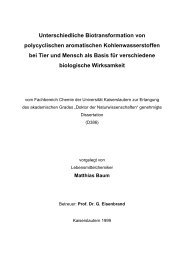
F<strong>ig</strong>ure 1 shows the oxidized Al thickness as a function of the ion dose determined from reflection<br />
(solid line) and resistance (dashed lines) measurements during oxidization with 30 eV and<br />
62 eV O + -ions. Both methods show nearly identical behaviors of the oxidation process. For low<br />
_____________________________________________________________________________________________________________________________________________________________________________________________________________________________________<br />
AG Magnetismus<br />
<strong>Universität</strong> <strong>Kaiserslautern</strong><br />
21
6 Experimental Results<br />
_____________________________________________________________________________________________________________________________________________________________________________________________________________________________________<br />
1.3x10 16<br />
62 eV<br />
30 eV<br />
F<strong>ig</strong>. 1: Oxidized Al thickness<br />
determined by optical reflection<br />
(solid line) and resistance<br />
(dashed line) measurements<br />
during the oxidation process.<br />
The energies of the ions are<br />
indicated. The open circles (°)<br />
correspond to the effective<br />
barrier width of MTJs determined<br />
by I(V)-curves, scaled to<br />
the oxidized Al thickness.<br />
ion doses (< 1.3⋅10 16 cm -2 ) the Al-film oxidizes rapidly with the rate depending on the ion energy.<br />
For h<strong>ig</strong>her doses the oxidation process slows down and becomes independent of the ion energy.<br />
At very h<strong>ig</strong>h doses the oxidation saturates.<br />
The effective barrier width shown in F<strong>ig</strong>. 1 by open circles (°) is derived from measured I(V)curves<br />
using Brinkman's model [4] for asymmetric tunnel barriers. As it is seen from F<strong>ig</strong>. 1 the<br />
fitted values of the barrier width, scaled to the oxidized Al thickness, follow the behavior which<br />
is expected from the oxidation measurements on metallic Al.<br />
In order to study the penetration of oxygen ions into Al, Monte-Carlo simulations were performed<br />
by using the TRIM-code [5]. The penetration of low energetic O + -ions in metallic Al is<br />
simulated. Even if TRIM does not take into account the correct molecular interactions for low<br />
ion energies, it is applicable for single atomic target materials. Comparing the experimental data<br />
for the oxidation depth to the results of simulations, two different oxidation mechanisms are revealed:<br />
ion-embedding and diffusion. For low doses almost every incoming O + -ion finds an incompletely<br />
oxidized Al atom as a reaction partner near its stopping point and forms directly<br />
AlOx. An Al-AlOx film is formed. The oxide is spread statistically in the Al film, with a h<strong>ig</strong>her<br />
penetration depth for h<strong>ig</strong>her ion energies. The very low ion dose (∼ 10 16 cm -2 ) needed to oxidize<br />
the first nanometer of Al is a clear indication for the h<strong>ig</strong>h efficiency of the ion-embedding<br />
mechanism.<br />
For h<strong>ig</strong>her oxygen doses the dominating oxidation mechanism is diffusion. The incoming O + -<br />
ions find less and less non- or incompletely oxidized Al partners near their stopping points. To<br />
form a chemical bond with Al, either O or Al ions needs to diffuse through Al2O3. Thus, the<br />
oxidation depth is determined by the penetration depth of the ions and the diffusion. The oxidation<br />
rate in this stage is independent of the initial ion energy. Note that an electrical field effecting<br />
the diffusion is changing with growing Al2O3 thickness [6].<br />
It is necessary to mention, that an ion assisted diffusion mechanism is discussed in the literature<br />
[7, 8]. Here the collisions of the incoming ions produce vacancies or defects in the material,<br />
which enhance the diffusion coefficients for oxygen and metallic atoms in the oxide. To check<br />
the importance of this mechanism the following experiment was carried out: the plasma reactor<br />
was filled with inert Ar, producing the same ion beam current as in our standard experimental<br />
conditions for ion oxidation, whereas non-ionized oxygen with the same flow rate as for the<br />
_____________________________________________________________________________________________________________________________________________________________________________________________________________________________________<br />
22 AG Magnetismus<br />
<strong>Universität</strong> <strong>Kaiserslautern</strong>
6 Experimental Results<br />
_____________________________________________________________________________________________________________________________________________________________________________________________________________________________________<br />
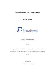
junction resistance [ Ω]<br />
10000<br />
1000<br />
standard experiment was let into the oxidation chamber. Thus the oxidizing Al film was simultaneously<br />
effected by the inert ion beam and the oxygen atmosphere. The obtained oxidation<br />
depth of about 0.6 nm is h<strong>ig</strong>her than the value observed in thermal oxidation, but it is still much<br />
smaller than the oxidation depth determined by ion-embedding followed by diffusion.<br />
F<strong>ig</strong>ure 2 shows the junction resistance and the TMR-effect for different MTJs, all prepared using<br />
30-eV-ions with an initial Al layer of 1.8 nm thickness and at various ion doses. The junction<br />
resistance is strongly increasing with the ion dose. The barrier parameters derived [9] from I(V)<br />
measurements show an increasing barrier width (see F<strong>ig</strong>. 1) with a nearly constant barrier he<strong>ig</strong>ht<br />
of about 2.1 eV. This fact corroborates the h<strong>ig</strong>h quality of the obtained barriers.<br />
The TMR-values measured at low applied voltages reach 14% for low ion doses, and they are<br />
reduced to about 7.5% at h<strong>ig</strong>h doses. The decrease takes place at about the dose where the transition<br />
from ion-embedding as the dominating oxidation mechanism to diffusion occurs. After<br />
the transition to diffusion no further TMR reduction occurs. The or<strong>ig</strong>in of this behavior is not<br />
clear yet, but it m<strong>ig</strong>ht be connected with structural effects in the formed Al2O3-layer. In fact, the<br />
ion-embedding oxidation should occur more or less homogeneously over the Al-layer, whereas<br />
the diffusion process would take place mainly along the crystallite grain boundaries.<br />
The work was supported by the Deutsche Forschungsgemeinschaft. The authors would like to<br />
thank D. Ozkaya and M. Rickart for performing TEM and STM measurements, respectively.<br />
Technical assistance of CCR GmbH and discussions with W. Maas are gratefully acknowledged.<br />
References<br />
100<br />
10<br />
1<br />
embedding<br />
[1] M. Weiler, K. Lang, E. Li, J. Robertson, Appl. Phys. Lett. 72, 1314 (1998).<br />
[2] B.F.P. Roos, P A. Beck, S.O. Demokritov, B. Hillebrands, D. Ozkaya, J. Appl. Phys. 89, 6656 (2001).<br />
[3] K. Fuchs, Proc. Camb. Phil. Soc. 34, 100 (1938); E.H. Sondheimer, Advan. Phys. 1, 1 (1952).<br />
[4] W.F. Brinkman, R.C. Dynes, J.M. Rowell, J. Appl. Phys. 41, 1915 (1970).<br />
[5] SRIM 2000 code, J.F. Ziegler, J.P. Biersack, U. Littmark, The Stopping and Range of Ions in Solids, Pergamon,<br />
New York, Oxford (1985).<br />
[6] A.T. Fromhold, Theory of metal oxidation, Volume I-Fundamentals, North-Holland, Amsterdam (1976).<br />
[7] A.H. Eltoukhy, J.E. Greene, J. Appl. Phys. 51, 4444 (1980).<br />
[8] H. Metiu, A.E. DePristo, J. Chem. Phys. 91, 2735 (1989).<br />
[9] E. Girgis, H. Boeve, J. De Boeck, J. Schelten, P. Rottlander, H. Kohlstedt, P. Grünberg, J. Mag. Mag. Mat.<br />
222, 133 (2000).<br />
_____________________________________________________________________________________________________________________________________________________________________________________________________________________________________<br />
AG Magnetismus<br />
<strong>Universität</strong> <strong>Kaiserslautern</strong><br />
diffusion<br />
TMR-effect<br />
junction resistance<br />
1 10<br />
16 2<br />
ion dose [10 /cm ]<br />
15.0<br />
12.5<br />
10.0<br />
7.5<br />
5.0<br />
2.5<br />
0.0<br />
TMR-effect [%]<br />
F<strong>ig</strong>. 2: Junction resistance (°)<br />
and TMR values (•) as a<br />
function of the oxygen ion<br />
dose.<br />
23
6 Experimental Results<br />
_____________________________________________________________________________________________________________________________________________________________________________________________________________________________________<br />
6.2 Surface smoothing by low energy ion bombardment<br />
S.O. Demokritov, B.F.P. Roos, M. Rickart, and B. Hillebrands<br />
The preparation of perfect smooth surfaces is a superior goal of many thin film technologies.<br />
There are several ways to approach this goal. One route is epitaxial layer-by-layer growth of the<br />
film on an appropriate substrate. A second route is to smooth the surface after the growth. If<br />
thin films and microscopic roughness on the nanometer scale are considered there are very few<br />
ways to smooth the surface, since standard techniques (mechanical and chemical polishing) are<br />
not appropriate due to obvious reasons. The only ways to improve the nano-roughness are to<br />
anneal the surface in ultra h<strong>ig</strong>h vacuum (UHV) [1] or in special atmosphere [2], or to bombard<br />
the surface with different species. Middle energy electrons were used to smooth surfaces of<br />
metallic Cr [3] and Co [4] films. Recently it was reported that bombardment of different films in<br />
magnetic tunnel junction stacks with gas clusters may cause an essential improvement of their<br />
tunnel magnetoresistance characteristics [5]. Here we report on the application of low energy<br />
ionized atoms. As an example, smoothing of an insulating surface (MgO(001)) and a metallic<br />
surface (Fe(001)) are discussed. We show that in the case of MgO the ion beam treatment not<br />
only smoothes the surface, but also removes carbon contaminations [6].<br />
The surface of commercially available MgO substrates (10×10 mm 2 ) is contaminated by water<br />
and carbon and it is relatively rough. To prepare clean MgO(001) surfaces, the samples are preheated<br />
in UHV at a moderate temperature of 150 o C for 30 min to remove water from the surface<br />
and then treated with an atomic oxygen ion beam at room temperature, as described below.<br />
Metallic Fe(001) films with a thickness of 5 nm are grown on MgO in UHV at 200 o C using an<br />
electron beam evaporator with a deposition rate of about 0.01 nm/s. To improve the roughness<br />
of the Fe-films they are first annealed at 400 o C and then treated with an argon ion beam. The<br />
surface topography is studied with a commercial Park Scientific Instruments Autoprobe VP 2<br />
UHV device, which is a combined atomic force (AFM) and scanning tunneling microscope<br />
(STM). AFM with a typical lateral resolution of 3 nm is used for invest<strong>ig</strong>ations of insulating<br />
MgO.<br />
The ion beam treatment is performed using a novel type of an excited electron cyclotron wave<br />
F<strong>ig</strong>. 1: AFM images of a MgO surface, a) before the treatment, RMS = 0.7 nm , b) after the ion beam treatment,<br />
RMS 0.1 nm. The insets show the corresponding LEED patterns at an energy of 107 eV.<br />
_____________________________________________________________________________________________________________________________________________________________________________________________________________________________________<br />
24 AG Magnetismus<br />
<strong>Universität</strong> <strong>Kaiserslautern</strong>
6 Experimental Results<br />
_____________________________________________________________________________________________________________________________________________________________________________________________________________________________________<br />
F<strong>ig</strong>. 2: STM images of an Fe(001) surface, a) before the treatment, RMS = 2.5 nm , b) after the ion beam<br />
treatment, RMS 0.175 nm. Note the change in the gray scales between both panels.<br />
resonance (ECWR) controlled plasma reactor (COPRA 160, CCR Technology). The reactor is a<br />
h<strong>ig</strong>h frequency, low pressure plasma source with an inductive excitation. A crucial advantage of<br />
the source is its ability to produce low energy (20-100 eV) ion beams. The ion beam is automatically<br />
neutralized by a corresponding electron current, thus minimizing charging effects on<br />
the substrate. The filament free des<strong>ig</strong>n of the source allows one to perform the ion treatment<br />
without contamination of the surface by the filament material. The source produces an oxygen<br />
beam with a dissociation <strong>deg</strong>ree of up to 80 %. The ion current density is chosen to be<br />
0.1 mA/cm 2 and a process time of 2 min, providing an ion dose of 6×10 16 ions/cm 2 . Ions with<br />
the nomi<strong>nal</strong> energy of 30–50 eV and an energy distribution width below 10 % of the nomi<strong>nal</strong><br />
energy are used for the ion beam treatment. The ion current density and the ion energy are<br />
monitored using a Faraday cup. A detailed technical description of the source can be found<br />
elsewhere [7].<br />
F<strong>ig</strong>ure 1 shows AFM topography images of a MgO(001) sample before and after the ion beam<br />
treatment with 35 eV O + -ions. The measured root mean square (RMS) roughness before the<br />
treatment is 0.7 nm. As seen in F<strong>ig</strong>. 1 the ion-beam treated surface is much smoother showing a<br />
measured RMS roughness as small as about 0.1 nm. Note here, that due to averaging over the<br />
finite lateral resolution of the AFM (typically 3 nm) monatomic steps on MgO cannot be resolved.<br />
Auger electron spectroscopy (not shown) indicates that the carbon contamination with<br />
the effective thickness of 0.4 ML is completely removed after the bombardment.<br />
Similar results are also obtained for smoothening of Fe(001) films. Unlike MgO, the bombardment<br />
of the Fe film is performed with Ar + -ions instead of oxygen to avoid oxidation of Fe. F<strong>ig</strong>ure<br />
2 presents STM images of Fe the surface before and after the ion beam treatment with 45 eV<br />
Ar + -ions. The essential smoothing of the surface is obvious from a comparison of F<strong>ig</strong>s. 2a and<br />
2b. The measured RMS value of the untreated films is 2.5 nm, while that of the treated film is<br />
below 0.18 nm.<br />
It is necessary to note that the energy of the ions is a very important parameter of the treatment.<br />
For the used energies the sputtering rate is found to be negl<strong>ig</strong>ible.<br />
Support by the Deutsche Forschungsgemeinschaft is gratefully acknowledged.<br />
_____________________________________________________________________________________________________________________________________________________________________________________________________________________________________<br />
AG Magnetismus<br />
<strong>Universität</strong> <strong>Kaiserslautern</strong><br />
25
6 Experimental Results<br />
_____________________________________________________________________________________________________________________________________________________________________________________________________________________________________<br />
References<br />
[1] S.M. Jordan, J.F. Lawler, R. Schad, H. van Kempen, J. Appl. Phys. 84 1499 (1998).<br />
[2] L.W. Guo, T. Hanada, H.J. Ko, Y.F. Chen, H. Makino, T. Yao, Surf. Sci. 445, 151 (2000).<br />
[3] S.O. Demokritov, J.A. Wolf, P. Grünberg, Appl. Phys. Lett. 63, 2147 (1993).<br />
[4] R. Allenspach, A. Bischof, U. Dür<strong>ig</strong>, P. Gütter, Appl. Phys. Lett. 73, 3598 (1998).<br />
[5] J.J. Sun, K. Shimazawa, N. Kasahara, K. Sato, S. Saruki, S. Araki, M. Matsuzaki, , J. Appl. Phys. 89, 6653<br />
(2001).<br />
[6] M. Rickart, B.F.P. Roos, T. Mewes, J. Jorzick, S.O. Demokritov, B. Hillebrands, Surf. Sci. in press.<br />
[7] M. Weiler, K. Lang, E. Li, J. Robertson, Appl. Phys. Lett. 72, 1314 (1998).<br />
_____________________________________________________________________________________________________________________________________________________________________________________________________________________________________<br />
26 AG Magnetismus<br />
<strong>Universität</strong> <strong>Kaiserslautern</strong>
6 Experimental Results<br />
_____________________________________________________________________________________________________________________________________________________________________________________________________________________________________<br />
B. Dynamic Magnetic Phenomena<br />
6.3 Spin wave wells in non-ellipsoidal micrometer size magnetic stripes<br />
S.O. Demokritov, J. Jorzick, and B. Hillebrands 1<br />
We report on the study of dynamic excitations in long, thin magnetic stripes magnetized in the<br />
stripe plane and perpendicular to their axes. Due to demagnetizing effects, the inter<strong>nal</strong> field of<br />
these stripes is intrinsically inhomogeneous. A novel, strongly spatially localized spin wave<br />
mode is observed. This mode appears near those edges of the stripes that are perpendicular to<br />
the applied magnetic field. The spatial localization takes place due to the h<strong>ig</strong>h inhomogeneity of<br />
the inter<strong>nal</strong> field in these regions, which creates a potential well for the spin waves.<br />
The invest<strong>ig</strong>ated samples were prepared from d = 30 – 35 nm thick permalloy (Ni80Fe20) films,<br />
which were grown by thermal evaporation on chemically cleaned Si(111) substrates at room<br />
temperature in UHV. Patterning was performed by means of e-beam lithography, reactive ion<br />
etching and argon ion etching using photoresist/germanium layers as intermediate masks. Stripe<br />
arrays with a width of w = 1 µm, a length of 90 µm, and a distance between the stripes of 0.3 –<br />
1 µm were prepared. Thermally excited spin waves were invest<strong>ig</strong>ated in backscattering geometry<br />
using a Brillouin l<strong>ig</strong>ht scattering (BLS) spectrometer described in [1].<br />
It has been recently shown [2, 3] that the intensity of l<strong>ig</strong>ht inelastically scattered from laterally<br />
confined spin wave modes for a given transferred wavevector Q is proportio<strong>nal</strong> to the Fourier<br />
component of the mode profile squared, mQ 2 , of the dynamic magnetization. Thus, by measuring<br />
the BLS intensity as a function of Q one can derive the spatial profile m(r). The interval in Q, in<br />
which a s<strong>ig</strong>nificant BLS intensity is observed, is inversely proportio<strong>nal</strong> to the confinement width<br />
of the mode in the real space, ∆ Q ≈ 2 π / ∆r<br />
.<br />
For reference, F<strong>ig</strong> 1a shows the dispersion of spin wave modes in the Damon-Eshbach (DE) geometry,<br />
in which the exter<strong>nal</strong> field He = 500 Oe is perpendicular to Q and is along the stripe<br />
axis. Demagnetizing effects are negl<strong>ig</strong>ible in this geometry. The results clearly demonstrates<br />
the lateral quantization of the DE spin waves, resembling a typical "staircase"-dispersion [2, 4].<br />
5 −1<br />
The interval of the observation of each mode in the Q-space ∆Q ≈ ( 0.<br />
8 −1)<br />
⋅10<br />
cm is in<br />
5 −1<br />
agreement with the width of the stripe w = 1 µm, giving 2π<br />
/ w = 0.<br />
63⋅10<br />
cm . The frequency<br />
of the perpendicular standing spin wave mode (PSSW) coincides with that of the PSSW mode<br />
for the unpatterned film and corresponds to an inter<strong>nal</strong> field of H = He = 500 Oe, thus corroborating<br />
negl<strong>ig</strong>ible demagnetizing effects in the stripes magnetized along their long axes. The frequencies<br />
of the observed modes are calculated as described below. The results of the calculations<br />
are shown in F<strong>ig</strong>. 1a by horizontal solid lines.<br />
F<strong>ig</strong>. 1b shows the results for He perpendicular to the stripe axis, i.e., demagnetizing effects are<br />
large. The dispersion, obtained in the so-called backward volume magnetostatic spin wave<br />
(BWVMS) geometry (He || Q), differs completely from that shown in F<strong>ig</strong>. 1a. First, the PSSW<br />
mode is splitted into two modes, with frequencies corresponding to inter<strong>nal</strong> fields of H = 300 Oe<br />
and H = 0 Oe, respectively. This confirms the fact, that in such a geometry the inter<strong>nal</strong> field is<br />
determined by an essential demagnetizing effect in the center region of the stripe, and can be<br />
zero near the edges, where the exter<strong>nal</strong> field enters and exits the stripe [5]. Second, a broad peak<br />
is seen in the spectra in the frequency range 5.5 – 7.5 GHz. The shape of the peak varies with Q,<br />
_____<br />
1<br />
In collaboration with M. Bailleul and C. Fermon, CEA Saclay, France; and K. Guslienko and A.N. Slavin, Oakland<br />
University, USA.<br />
_____________________________________________________________________________________________________________________________________________________________________________________________________________________________________<br />
AG Magnetismus<br />
<strong>Universität</strong> <strong>Kaiserslautern</strong><br />
27
6 Experimental Results<br />
_____________________________________________________________________________________________________________________________________________________________________________________________________________________________________<br />
Frequency (GHz)<br />
20<br />
16<br />
12<br />
8<br />
4<br />
p = 1 (PSSW)<br />
m = 5<br />
m = 4<br />
m = 3<br />
m = 2<br />
m = 1<br />
He<br />
Q<br />
0<br />
0 1 2<br />
Frequency (GHz)<br />
20<br />
16<br />
12<br />
8<br />
4<br />
p = 1<br />
(PSSW)<br />
He<br />
LM<br />
H = 300 Oe<br />
Band<br />
H = 0 Oe<br />
0<br />
0 1 2<br />
Q (10 5 cm -1 )<br />
thus indicating different contributions of unresolved modes to the scattering cross section at different<br />
Q. Third, a separate, low frequency, dispersionless mode with a frequency near 4.6 GHz<br />
(indicated as "LM" in F<strong>ig</strong>. 1b) is observed over the entire accessible wavevector range<br />
5 −1<br />
Q max ≈ 2.<br />
5 ⋅10<br />
cm with almost constant intensity. This is a direct confirmation of a strong<br />
lateral localization of the mode within a region with the width 2 / max 0.<br />
25 = π <<br />
Q (10<br />
∆r Q µm. From<br />
the low frequency of the mode one can conclude that it is localized near the edges of the elements,<br />
since these are the field-free regions [5, 6].<br />
5 cm -1 )<br />
a)<br />
b)<br />
A quantitative a<strong>nal</strong>ytical description of the spin wave modes observed in the stripes can be found<br />
elsewhere [7]. We will illustrate the main ideas in the following. The profile of the inter<strong>nal</strong> field<br />
H over the stripe is shown in the inset of F<strong>ig</strong>. 2. For H > 0 the magnetization is parallel to He.<br />
Near the edges, however, regions with H = 0 and regions with continuously rotating magnetization<br />
are formed. Since the rotation of the static magnetization dramatically changes the dispersion<br />
of spin waves, regions with zero inter<strong>nal</strong> field will reflect spin waves propagating from the<br />
middle of the stripe towards these regions. On the other hand, a spin wave of a given frequency<br />
propagating in an inhomogeneous field m<strong>ig</strong>ht encounter a turning point even if the magnetization<br />
is uniform. In fact, for large enough values of the inter<strong>nal</strong> field there are no allowed real values<br />
of Q, consistent with the spin wave dispersion [8]. Thus, the inhomogeneous inter<strong>nal</strong> magnetic<br />
field creates a potential well with two turning points for propagating spin waves. This well can<br />
severely restrict the spatial region of spin wave existence. Similar to the potential well in quantum<br />
mechanics, the conditions determining the frequencies νr of possible spin wave states in the<br />
well created by the inhomogeneous inter<strong>nal</strong> field are determined by the equation:<br />
∫ Q ( H ( z),<br />
ν) dz = rπ<br />
, where r = 1,2,3,... and Q(H(z),ν) is found from the spin wave dispersion.<br />
The calculated dispersion curves for spin wave with Q || H are presented in F<strong>ig</strong>. 2. Different<br />
curves correspond to different constant values of the field as indicated. A solid horizontal line<br />
presenting the frequency of the lowest spin wave mode ν1 = 4.5 GHz obtained from the integral<br />
equation for r = 1 is in a good agreement with the experiment. It is seen from F<strong>ig</strong>. 2, that for<br />
H > 237 Oe there are no real values of Q for which the frequency ν1 = 4.5 GHz lies in the spectrum<br />
of spin waves. Therefore, the lowest mode can only exist in the spatial regions in the magnetic<br />
stripe where the inter<strong>nal</strong> field satisfies the condition 0 Oe < H < 237 Oe. The corresponding<br />
turning points are indicated in the inset in F<strong>ig</strong>. 2 by the vertical dash lines. Thus, the lowest<br />
mode is localized in the narrow region ∆z near the lateral edges of the stripe where<br />
_____________________________________________________________________________________________________________________________________________________________________________________________________________________________________<br />
28 AG Magnetismus<br />
<strong>Universität</strong> <strong>Kaiserslautern</strong><br />
Q<br />
F<strong>ig</strong>. 1: Spin wave dispersion<br />
of the wire array measured at<br />
He = 500 Oe for (a) the DEgeometry,<br />
(b) the BWVMSgeometry.<br />
The solid lines<br />
represent the results of calculation.
6 Experimental Results<br />
_____________________________________________________________________________________________________________________________________________________________________________________________________________________________________<br />
0.26 < |z/w| < 0.39. The mode is composed of plane waves with Qmin < Q < Qmax, as indicated in<br />
F<strong>ig</strong>. 2.<br />
Fi<strong>nal</strong>ly, we would like to point out a very peculiar feature of this localized mode. Being the<br />
lowest mode in the spectrum, it is in fact an exchange-dominated mode, since the dispersion of<br />
the contributing plane waves is mainly determined by the exchange interaction.<br />
Support by the Deutsche Forschungsgemeinschaft and the Stiftung für Innovation of the state of<br />
Rhineland Palatinate is gratefully acknowledged.<br />
References<br />
Frequency (GHz)<br />
10<br />
8<br />
6<br />
4<br />
2<br />
H (Oe)<br />
300<br />
200<br />
100<br />
Q min<br />
0<br />
0 2 4<br />
Q (10<br />
6 8<br />
5 cm -1 )<br />
[1] B. Hillebrands, Rev. Sci. Instr. 70, 1589 (1999).<br />
[2] J. Jorzick, S.O. Demokritov, B. Bartenlian, C. Chappert, F. Rousseaux, A.N. Slavin, B. Hillebrands, Phys. Rev.<br />
B 60, 15194 (1999).<br />
[3] J.F. Cochran, J. Mag. Mag. Mat. 212, 40 (2000).<br />
[4] C. Mathieu, J. Jorzick, A. Frank, S.O. Demokritov, B. Hillebrands, A.N. Slavin, B. Bartenlian, C. Chappert, D.<br />
Decanini, F. Rousseaux, E. Cambril, Phys. Rev. Lett. 81, 3968 (1998).<br />
[5] P. Bryant and H. Suhl, Appl. Phys. Lett. 54, 2224 (1989).<br />
[6] R.I. Joseph, E. Schloemann, J. Appl. Phys. 36, 1679 (1965).<br />
[7] J. Jorzick, S.O. Demokritov, B.Hillebrands, M. Bailleul , C. Fermon, K. Guslienko, A.N. Slavin, D.V. Berkov,<br />
and N.L. Gorn, Spin wave wells in non-ellipsoidal micrometer size magnetic elements, submitted to Phys. Rev.<br />
Lett.<br />
[8] E. Schlomann, R.I. Joseph, J. Appl. Phys. 35, 167 (1964).<br />
_____________________________________________________________________________________________________________________________________________________________________________________________________________________________________<br />
AG Magnetismus<br />
<strong>Universität</strong> <strong>Kaiserslautern</strong><br />
∆z<br />
0<br />
0.0 0.26<br />
z/w 0.39 0.5<br />
Q max<br />
H = 305 Oe<br />
H = 237 Oe<br />
H = 120 Oe<br />
H = 0 Oe<br />
ν 1 = 4.5 GHz<br />
F<strong>ig</strong>. 2: Dispersion of plane spin waves in the BWVMS-geometry at constant inter<strong>nal</strong> fields as indicated. Inset:<br />
the profile of the inter<strong>nal</strong> field in a wire. ∆z shows the region of the lowest mode localization.<br />
29
6 Experimental Results<br />
_____________________________________________________________________________________________________________________________________________________________________________________________________________________________________<br />
6.4 Spin wave localization in micrometer size magnetic rectangular<br />
elements<br />
S.O. Demokritov, J. Jorzick, and B. Hillebrands 1<br />
In the previous contribution (Section 6.3) we discussed the observation of a novel, strongly spatially<br />
localized spin wave mode in long magnetic stripes. Here we report a theoretical and experimental<br />
study of a similar localized mode in micrometer size rectangular elements. The spatial<br />
localization of the mode also takes place due to the h<strong>ig</strong>h inhomogeneity of the inter<strong>nal</strong> field<br />
near the edges of the elements. Unlike to the stripes, however, the mode is observed in all inplane<br />
orientations of the applied field, since for a rectangular element one can always find edges<br />
of the element, which are not parallel to the applied magnetic field.<br />
The invest<strong>ig</strong>ated samples were prepared from d = 33 nm thick permalloy (Ni80Fe20) films, which<br />
were grown by thermal evaporation on chemically cleaned Si(111) substrates at room temperature<br />
in UHV. Similar to the stripe samples patterning of the rectangular elements was performed<br />
by means of e-beam lithography, reactive ion etching and argon ion etching using germanium<br />
layers as intermediate masks. The elements have lateral dimensions of 1×(1–2) µm 2 . The spacing<br />
δ = 0.1 – 1 µm between the elements was always chosen the same in both lateral directions.<br />
The elements were arranged in arrays with dimensions of 500×500 µm 2 . The h<strong>ig</strong>h quality of the<br />
patterning process is evident from F<strong>ig</strong>. 1a, where a scanning force microscope image of an array<br />
is shown.<br />
_____<br />
a) b)<br />
c)<br />
H = 600 Oe<br />
F<strong>ig</strong>. 1: a) AFM-image of rectangular elements; b) calculated distribution of static magnetization in an element;<br />
c) mode profile of a low frequency spin wave mode with ν = 5.3 GHz. Note the mode localization near the<br />
edges; d) mode profile of a spin wave mode with ν = 12.2 GHz.<br />
1 In collaboration with M. Bailleul and C. Fermon , CEA Saclay, France; K. Guslienko and A.N. Slavin, Oakland<br />
University, USA; and D.V. Berkov and N.L. Gorn, Innovent Jena, Germany.<br />
_____________________________________________________________________________________________________________________________________________________________________________________________________________________________________<br />
30 AG Magnetismus<br />
<strong>Universität</strong> <strong>Kaiserslautern</strong><br />
d)
6 Experimental Results<br />
_____________________________________________________________________________________________________________________________________________________________________________________________________________________________________<br />
Studies of thermally excited spin waves using a Brillouin l<strong>ig</strong>ht scattering spectrometer have<br />
shown the existence of a localized, low frequency mode in the rectangular elements. For example,<br />
the frequency of the mode for the array of rectangular elements with the lateral sizes<br />
1×1.75 µm 2 and the distance between the elements δ = 0.2 µm at the exter<strong>nal</strong> magnetic field<br />
He = 600 Oe applied along the long edge of the elements is 5.3 GHz.<br />
Since the a<strong>nal</strong>ytical approach presented in the preceding Section is essentially a one-dimensio<strong>nal</strong><br />
one, it cannot be applied directly to rectangular elements. Instead, micromagnetic simulations of<br />
the equilibrium thermodynamic properties of magnetic excitations in such elements were performed.<br />
The method is based on the Langevin-dynamics approach [1]. The time evolution of<br />
the magnetization distribution of the element discretized into cells with magnetic moments µi is<br />
simulated using the Landau-Lifshitz-Gilbert (LLG) equation. The effective field Hi eff acting on<br />
the i-th moment includes a deterministic part Hi det and a fluctuating part Hi fl . The former comprises<br />
the exter<strong>nal</strong> field and the effective fields due to exchange and dipolar interactions between<br />
different cell moments. The second effective field, simulating thermal fluctuations, has Cartesian<br />
components with well known statistical properties [2]. The LLG-equation with a fluctuating<br />
field was considered in the Stratonovich interpretation [3], and has been solved using the improved<br />
version of the Bulirsch-Stoer method specially adapted and optimized for solving stochastic<br />
differential equations.<br />
The starting state (F<strong>ig</strong>. 1b) for the simulation is obtained by solving the LLG equation without<br />
any fluctuating fields. Next, the field Hi fl is turned on. After the thermodynamic equilibrium<br />
state of the system is reached (i.e., the system energy did not exhibit any systematic change with<br />
time), the values of all cell moments obtained during the simulation are recorded as functions of<br />
time. Afterwards, using Fourier a<strong>nal</strong>ysis, the oscillation spectrum of the total magnetic moment<br />
of the element is obtained. In the frequency interval 3 – 20 GHz this Fourier spectrum demonstrates<br />
several maxima. The Fourier components of each cell magnetization µi,ω corresponding<br />
to these maxima are calculated and squared, to compare them with the measured spin wave intensities.<br />
As an example, the spatial distributions of spin wave modes with the frequencies<br />
ν = 5.3 GHz and ν = 12.2 GHz are presented in F<strong>ig</strong>s. 1c and 1d. It is clear from F<strong>ig</strong>. 1c that the<br />
low-frequency mode is strongly localized in the narrow regions near the edges of the elements<br />
that are perpendicular to the applied field in accordance with the experiment and with the result<br />
of the a<strong>nal</strong>ytical a<strong>nal</strong>ysis performed for the stripes. In contrast, the mode with ν = 12.2 GHz<br />
shown in F<strong>ig</strong>. 1d is not localized, but is a result of a complicated two-dimensio<strong>nal</strong> lateral quantization<br />
of spin waves in the element.<br />
Fi<strong>nal</strong>ly, we have demonstrated that the e<strong>ig</strong>enmode spectrum of magnetic rectangular elements<br />
includes a low frequency, spatially localized spin wave mode of exchange nature. Similar to the<br />
stripes, the localization of the mode is caused by the inhomogeneity of the inter<strong>nal</strong> field. These<br />
modes must be taken into account for yielding a better understanding of, e.g., the fast magnetic<br />
switching properties in magnetic memory elements.<br />
Support by the Deutsche Forschungsgemeinschaft and the Stiftung für Innovation of the state of<br />
Rhineland Palatinate is gratefully acknowledged.<br />
References<br />
[1] J.L. Garcia-Palacios, F.J. Lazaro, Phys. Rev. B 58, 14937 (1998).<br />
[2] W.F. Brown, Jr., Phys. Rev. 130, 1677 (1963).<br />
[3] P.E. Kloeden, E. Platen, Numerical Solution of Stochastic Differential Equations, Springer, Berlin, 1995.<br />
_____________________________________________________________________________________________________________________________________________________________________________________________________________________________________<br />
AG Magnetismus<br />
<strong>Universität</strong> <strong>Kaiserslautern</strong><br />
31
6 Experimental Results<br />
_____________________________________________________________________________________________________________________________________________________________________________________________________________________________________<br />
6.5 Excitation and propagation of spin wave packets in thin garnet films by<br />
a short field pulse studied by space- and time-resolved magneto-optic<br />
Kerr effect magnetometry<br />
M. Bauer, R. Lopusnik, J. Fassbender, and B. Hillebrands<br />
Linear and nonlinear wave phenomena (e.g. self-focusing, solitons, bullets, etc.) are important<br />
subjects in both basic research and applications. Nonlinear wave effects have been experimentally<br />
observed in a large number of different physical systems. Specifically, for invest<strong>ig</strong>ations of<br />
excitation and propagation of wave packets in linear as well as in nonlinear media, thin magnetic<br />
garnet films with very low damping have proven to be a nearly perfect laboratory test system.<br />
By variation of the propagation direction and wavelength of the spin waves and/or the strength<br />
and direction of the applied magnetic field a large parameter space (e.g., group- and phase velocity,<br />
dispersion, diffraction, non-linearity, damping) is accessible with the same sample. Recently,<br />
we have developed an advanced Brillouin l<strong>ig</strong>ht scattering (TRBLS) setup, which allows<br />
one to map the spatial spin wave intensity distribution across the sample with time resolution [1].<br />
It is also advantageous to test spin wave excitations by a short field pulse and the propagation by<br />
an independent method, working directly on the time scale, which is the subject of this report.<br />
Utilizing a newly developed space- and time-resolved magneto-optic Kerr effect vector magnetometer<br />
setup [2] the excitation and propagation of spin wave packets in a thin bismuth substituted<br />
lutetium iron garnet (BiLuIG, Bi0.96Lu2.04Fe5O12) film grown on a gadolinium gallium garnet<br />
substrate have been invest<strong>ig</strong>ated [3].<br />
F<strong>ig</strong>ure 1 shows the experimental setup. A 8 mm long, 2 mm wide and 1.5 µm thin BiLuIG film<br />
was saturated by a static magnetic field of Hstat = 40 Oe along the y-direction, the short dimension<br />
of the film. A narrow, 50 µm wide microstrip transmission line was used for the pulse excitation.<br />
Magnetic field pulses of about 3 ns duration, 100 ps rise time, 200 ps fall time and<br />
Hpulse ≈ 1 Oe field amplitude were applied along the x-direction with a repetition rate of 100 kHz.<br />
The magneto-optic (MO) response of the generated spin waves was measured with an angle of<br />
l<strong>ig</strong>ht incidence of 55 <strong>deg</strong>.<br />
plane of l<strong>ig</strong>ht incidence<br />
magnetic field conf<strong>ig</strong>uration<br />
magnetic film<br />
substrate<br />
microstrip line<br />
dielectric substrate<br />
ground plane<br />
_____________________________________________________________________________________________________________________________________________________________________________________________________________________________________<br />
32 AG Magnetismus<br />
<strong>Universität</strong> <strong>Kaiserslautern</strong><br />
H stat<br />
H (t)<br />
pulse<br />
F<strong>ig</strong>. 1: Sample geometry, plane of l<strong>ig</strong>ht incidence, and magnetic field conf<strong>ig</strong>uration used in the experiment.<br />
Z<br />
Y<br />
X
6 Experimental Results<br />
_____________________________________________________________________________________________________________________________________________________________________________________________________________________________________<br />
F<strong>ig</strong>ure 2 shows the time evolution of the excitation and propagation of spin wave packets in a<br />
grayscale representation of the MO s<strong>ig</strong><strong>nal</strong> at different times t. At t = 1 ns the pulse excitation<br />
starts. For t = 1.4 ns the maximum deflection of the magnetization is reached on the microstrip<br />
t [ns]<br />
1<br />
1.4<br />
1.85<br />
2.35<br />
2.85<br />
3.3<br />
v gr = 6.6 cm/µs<br />
Tpulse ≈ 3 ns<br />
3.2 mm<br />
1.8 mm<br />
_____________________________________________________________________________________________________________________________________________________________________________________________________________________________________<br />
AG Magnetismus<br />
<strong>Universität</strong> <strong>Kaiserslautern</strong><br />
3.8<br />
4.25<br />
4.75<br />
5.2<br />
5.7<br />
6.15<br />
6.65<br />
7.1<br />
7.6<br />
8.05<br />
8.55<br />
F<strong>ig</strong>. 2: <strong>Time</strong> evolution of the excitation and propagation of spin wave packets. Shown here is a sequence of the<br />
mapped magneto-optic s<strong>ig</strong><strong>nal</strong> in a grayscale representation at different times t. Br<strong>ig</strong>ht (dark) areas indicate a<br />
positive (negative) deflection of the magnetization from the equilibrium direction. The field pulses of ≈3 ns<br />
duration start at t = 1 ns. The arrows indicate the propagation of the wave packets with a group velocity of<br />
vgr = 6.6 cm/µs.<br />
9<br />
9.5<br />
10<br />
33
6 Experimental Results<br />
_____________________________________________________________________________________________________________________________________________________________________________________________________________________________________<br />
a) X [mm] =<br />
0.7<br />
b)<br />
MO s<strong>ig</strong><strong>nal</strong><br />
0 1 2 3 4 5 6 7 8 9 10<br />
time [ns]<br />
0.6<br />
0.5<br />
0.4<br />
0.3<br />
0.2<br />
0.1<br />
0.0<br />
-0.1<br />
-0.2<br />
-0.3<br />
-0.4<br />
-0.5<br />
-0.6<br />
-0.7<br />
FFT s<strong>ig</strong><strong>nal</strong><br />
ν 0 = 0.83 GHz<br />
ν k = 1.05 GHz<br />
0.6 0.7 0.8 0.9 1.0 1.1 1.2 1.3 1.4<br />
frequency [GHz]<br />
X [mm] =<br />
0.7<br />
0.6<br />
0.5<br />
0.4<br />
0.3<br />
0.2<br />
0.1<br />
0.0<br />
-0.1<br />
-0.2<br />
-0.3<br />
-0.4<br />
-0.5<br />
-0.6<br />
-0.7<br />
F<strong>ig</strong>. 3: Response of the MO s<strong>ig</strong><strong>nal</strong> in time (a) and frequency space (b) for different distances to the microstrip<br />
transmission line. The frequency of the uniform and the propagating spin wave mode were determined to be<br />
ν0 = 0.83 GHz and νk = 1.05 GHz, respectively.<br />
indicated by the white strip. Two spin wave packets begin to form on each side of the strip, and<br />
they propagate from the localized field region near the microstrip away to both sides. The<br />
propagation of the spin wave packets is clearly noticeable. From the data a group velocity of<br />
vgr = 6.6 cm/µs is determined.<br />
In F<strong>ig</strong>. 3 the response of the MO s<strong>ig</strong><strong>nal</strong> is shown as a function of time (a) and frequency (b) for<br />
different distances to the microstrip. The frequency spectra (b) are calculated from the time response<br />
data (a) by means of a fast Fourier transformation. At the microstrip position two peaks<br />
in the frequency spectra are clearly visible. They have been identified as the uniform precession<br />
mode (index ‘0’) and the propagating spin wave mode (index ‘k’) with frequencies of<br />
ν0 = 0.83 GHz and νk = 1.05 GHz, respectively. Note that, first, the intensity of the uniform precession<br />
mode decreases very rapidly in x-direction. Thus this mode is localized near the microstrip.<br />
Second, the intensity of the propagating mode is nearly constant. This mode carries energy<br />
away from the microstrip area. In F<strong>ig</strong>. 3b the intensity of this mode breaks down because<br />
the MO response in a too short time range of 10 ns only has been recorded. During this time the<br />
spin wave packet did not pass completely the points at large distances form the microstrip.<br />
F<strong>ig</strong>ure 4 shows the MO s<strong>ig</strong><strong>nal</strong> averaged over the y-direction as a function of the distance x from<br />
the microstrip for different times. The dotted arrows indicate points with constant phase. From<br />
their slope the phase velocity has been determined to vph = 34 cm/µs. The distance between consecutive<br />
arrows in x-direction at a constant time corresponds to a wavelength of λ = 0.03 cm and<br />
a wave vector of kx = 210 cm -1 , respectively. The gray arrow on the left represents the center of<br />
gravity of the spin wave packet. It moves with the group velocity, which is much slower than<br />
_____________________________________________________________________________________________________________________________________________________________________________________________________________________________________<br />
34 AG Magnetismus<br />
<strong>Universität</strong> <strong>Kaiserslautern</strong>
6 Experimental Results<br />
_____________________________________________________________________________________________________________________________________________________________________________________________________________________________________<br />
the phase velocity. The marker on the r<strong>ig</strong>ht is used to determine the carrier precession period to<br />
Tk = 0.95 ns and the frequency to νk = 1.05 GHz.<br />
Fi<strong>nal</strong>ly, the measured parameters presented above are compared to a simple model calculation.<br />
In the present case the propagating spin wave mode is a magneto-static surface wave (MSSW)<br />
mode, since both the direction of the magnetic field and the wave vector lie perpendicular to<br />
each other in the film plane. From the dispersion relation of the MSSW mode<br />
_____________________________________________________________________________________________________________________________________________________________________________________________________________________________________<br />
AG Magnetismus<br />
<strong>Universität</strong> <strong>Kaiserslautern</strong><br />
2<br />
( 4 ) ( 2 ) ( 1 exp( 2 ) )<br />
ω = γ H H + π M + πM − − k d (1)<br />
k stat stat S S X<br />
the phase and group velocities are calculated as<br />
and<br />
∂ω<br />
MO s<strong>ig</strong><strong>nal</strong><br />
k vgr = = 6.3cm µs<br />
∂kX<br />
kX<br />
ω<br />
= = , (3)<br />
k vph 31cm µs<br />
kX<br />
kX = 210 cm -1<br />
Tk = 0.95 ns<br />
ν k = 1.05 GHz<br />
v = 34 cm/µs<br />
ph<br />
-1.0 -0.5 0.0 0.5 1.0<br />
X [mm]<br />
λ = 0.03 cm<br />
t [ns] =<br />
10.00<br />
9.85<br />
9.70<br />
9.55<br />
9.40<br />
9.25<br />
9.10<br />
8.95<br />
8.80<br />
8.65<br />
8.50<br />
8.35<br />
8.20<br />
8.05<br />
7.90<br />
7.75<br />
7.60<br />
F<strong>ig</strong>. 4: Determination of phase velocity vph = 34 cm/µs, wave length λ = 0.03 cm, wave vector kX = 210 cm -1 ,<br />
precession period Tk = 0.95 ns, and frequency νk = 1.05 GHz of the propagating spin wave mode.<br />
respectively. |γ| = 0.0176 (Oe ns) -1 denotes the gyromagnetic ratio, Hstat = 40 Oe is the applied<br />
static magnetic field, kX = 210 cm -1 is the wave vector and d = 1.5 µm is the film thickness.<br />
(2)<br />
35
6 Experimental Results<br />
_____________________________________________________________________________________________________________________________________________________________________________________________________________________________________<br />
Only the saturation magnetization has been adjusted to 4πMS = 1950 Oe. Table 1 shows a comparison<br />
between the measured and calculated values. Within the limits of this model there is a<br />
good agreement between the measured and calculated values.<br />
The presented method has several advantages compared to measurements with conventio<strong>nal</strong> microwave<br />
techniques utilizing miniaturized pickup coils. The lateral resolution is better and it is<br />
practically free of cross talk, i.e., a direct electromagnetic coupling between the microstrip and a<br />
pickup coil. Compared to space- and time-resolved Brillouin l<strong>ig</strong>ht scattering, where the intensity<br />
is measured, the phase of the spin waves is directly accessible. The time resolution is improved<br />
by two orders of magnitude. Furthermore all three components of the magnetization can be<br />
measured [4]. On the other hand, a much longer acquisition time and the loss of direct wave<br />
vector selectivity must be taken into account.<br />
Work supported by the Deutsche Forschungsgemeinschaft, the BMBF (Leitprojekt Magnetoelektronik)<br />
and the EC-TMR program "DYNASPIN" No. FMRX-CT97-0124.<br />
References<br />
experiment model<br />
frequency of the uniform mode ν0 = 0.83 GHz ν0 = 0.79 GHz<br />
frequency of the propagating mode νk = 1.05 GHz νk = 1.04 GHz<br />
phase velocity vph = 34 cm/µs vph = 31 cm/µs<br />
group velocity vgr = 6.6 cm/µs vgr = 6.3 cm/µs<br />
Tab. 1: Comparison between measured and calculated values.<br />
[1] M. Bauer, O. Büttner, S.O. Demokritov, B. Hillebrands, V. Grimalsky, Yu. Rapoport, A.N. Slavin, Phys. Rev.<br />
Lett. 81, 3769 (1998).<br />
[2] M. Bauer, R. Lopusnik, J. Fassbender, B. Hillebrands, Appl. Phys. Lett. 76, 2758 (2000).<br />
[3] M. Bauer, Ph.D. thesis, <strong>Universität</strong> <strong>Kaiserslautern</strong> (2001).<br />
[4] R. Lopusnik, Ph.D. thesis, <strong>Universität</strong> <strong>Kaiserslautern</strong> (2001).<br />
_____________________________________________________________________________________________________________________________________________________________________________________________________________________________________<br />
36 AG Magnetismus<br />
<strong>Universität</strong> <strong>Kaiserslautern</strong>
6 Experimental Results<br />
_____________________________________________________________________________________________________________________________________________________________________________________________________________________________________<br />
6.6 Excitation and propagation of spin wave packets in thin garnet films<br />
by a short field pulse using space- and time-resolved Brillouin l<strong>ig</strong>ht<br />
scattering spectroscopy<br />
M. Bauer and B. Hillebrands 1<br />
Spin waves have been observed using the space- and time-resolved magneto-optic Kerr effect, as<br />
discussed in the preceding Section 6.5. Subject of this report is the demonstration that spin<br />
waves excited by a single current pulse can be detected by a spectroscopic technique like Brillouin<br />
l<strong>ig</strong>ht scattering with space and time resolution (TRBLS). New for this approach is the nonresonant<br />
excitation of spin waves, as opposite to the excitation with a harmonic microwave<br />
driving field.<br />
In the experiment a thin single-crystalline yttrium iron garnet (YIG) film (thickness 7 µm, width<br />
18 mm, length 26 mm, saturation magnetization 1750 Oe, FMR line width FWHM 0.6 Oe at<br />
4 GHz) is saturated by a static magnetic field of 800 Oe parallel to the long film side. A 50 µm<br />
wide and 2 mm long microstrip transmission line antenna is al<strong>ig</strong>ned perpendicular to the applied<br />
static field. Thus the spin wave packets will propagate parallel to the applied static field. This<br />
spin wave mode is known as the magnetostatic backward volume wave (MSBVW) mode. The<br />
_____<br />
spin wave intensity<br />
BLS intensity<br />
0 20 40 60 80 100 120 140<br />
time [ns]<br />
1 In collaboration with V. Tyberkevich, Radiophysics Faculty, Natio<strong>nal</strong> Taras Shevchenko University of Kiev,<br />
Ukraine; and A. Slavin, Department of Physics, Oakland University, USA.<br />
_____________________________________________________________________________________________________________________________________________________________________________________________________________________________________<br />
AG Magnetismus<br />
<strong>Universität</strong> <strong>Kaiserslautern</strong><br />
simulation<br />
distance from antenna<br />
0.8 mm<br />
1.0 mm<br />
1.4 mm<br />
2.6 mm<br />
measurement<br />
F<strong>ig</strong>. 1: Excitation and propagation of spin<br />
wave packets. Shown is the simulated (top)<br />
and measured (bottom) time response of the<br />
spin wave intensity for different distances<br />
from the excitation antenna from 0.8 mm to<br />
2.6 mm.<br />
37
6 Experimental Results<br />
_____________________________________________________________________________________________________________________________________________________________________________________________________________________________________<br />
antenna is connected to a pulse generator able to create field pulses of about 5 Oe magnitude,<br />
280 ps pulse duration, 100 ps rise time (10% – 90%), and 200 ps fall time (90% – 10%).<br />
First, the excitation and propagation of spin wave packets have been invest<strong>ig</strong>ated. F<strong>ig</strong>ure 1<br />
shows the simulated (top) and measured (bottom) time response of the spin wave intensity for<br />
different distances from the excitation antenna from 0.8 mm to 2.6 mm. The data have been<br />
taken with the TRBLS technique in forward scattering geometry. The acquisition time for each<br />
time response curve was about 10 hours compared to a few seconds in the case of a microwave<br />
driving field. In order to compensate different acquisition times the intensity is normalized to<br />
the large residual background noise. The main issue is demonstrated clearly: single current<br />
pulses excite spin waves which are clearly detected in the TRBLS experiment.<br />
In order to understand the results we have made simulations of the expected spin wave response.<br />
Most of the qualitative features of the experiment can be seen in the simulation. The experimentally<br />
obtained times of arrival of the spin wave packet at the point of observation is well reproduced<br />
by the model calculation, as well as the profile of the excited pulse. In the simulations<br />
trapezoidal pulses with a duration of 280 ps, a rise time (0% – 100%) of 132 ps, a fall time<br />
(100% – 0%) of 266 ps, and a cosine lateral current distribution in the antenna have been used.<br />
It is remarkable that, although the duration of the excitation pulse is chosen equal to about one<br />
FMR precession period, the duration of the propagating spin wave packet is about 15 ns, thus 50<br />
times larger, as measured at a distance of 2.6 mm from the antenna. This can be understood by<br />
the fact, that these short pulses excite spin waves over a very wide frequency spectrum range.<br />
Since spin waves with different frequencies have different group velocities due to the dispersing<br />
character of the medium, the spin wave packet grows in width very fast after its generation.<br />
spin wave intensity<br />
60 80 100 120 140 160 180 200 220<br />
time [ns]<br />
measurement<br />
2.6 mm<br />
"Lorentz"<br />
"Cos"<br />
"Uniform"<br />
"Normal"<br />
F<strong>ig</strong>. 2: Comparison of the simulated time<br />
response of the spin wave intensity for<br />
different lateral current distributions across<br />
the excitation antenna with the experiment<br />
for a distance of 2.6 mm from the antenna.<br />
For the expressions of the current distributions<br />
see Eqs. (1) – (4).<br />
_____________________________________________________________________________________________________________________________________________________________________________________________________________________________________<br />
38 AG Magnetismus<br />
<strong>Universität</strong> <strong>Kaiserslautern</strong>
6 Experimental Results<br />
_____________________________________________________________________________________________________________________________________________________________________________________________________________________________________<br />
Second, the excitation pattern is very sensitive to the lateral current distribution across the antenna.<br />
Consequently this method has been used to compare different current distributions with<br />
the experimental data. F<strong>ig</strong>ure 2 shows the time response of the spin wave intensity for a distance<br />
of 2.6 mm from the antenna for the experimental data (top) and for different current distributions.<br />
The invest<strong>ig</strong>ated current distributions A(z) and the corresponding Fourier transforms Ak<br />
across the antenna of finite width w have the form:<br />
“Normal”: ( )<br />
( ) 2<br />
A z = (1a) 0 ( 2)<br />
1 − 2z<br />
w<br />
kw J Ak = (1b)<br />
“Uniform”: A ( z)<br />
= 1<br />
(2a)<br />
“Cos”: A( z)<br />
= cos(<br />
πz<br />
w)<br />
(3a)<br />
_____________________________________________________________________________________________________________________________________________________________________________________________________________________________________<br />
AG Magnetismus<br />
<strong>Universität</strong> <strong>Kaiserslautern</strong><br />
1<br />
1<br />
( kw 2)<br />
sin<br />
Ak = (2b)<br />
kw 2<br />
A k<br />
cos<br />
=<br />
1 −<br />
( kw 2)<br />
( kw π )<br />
“Lorentz”: ( )<br />
( ) 2<br />
A z = (4a) Ak = exp( − kw 2)<br />
(4b)<br />
1 + 2z<br />
w<br />
J0(x) is the Bessel function of zero order. The “Normal” distribution is referred to the current<br />
distribution according to the Maxwell electrodynamics theory.<br />
The different excitation patterns observed in F<strong>ig</strong>. 2 can be understood as follows. The sensitivity<br />
of the current distribution across the antenna strongly influences the wave vector spectrum of the<br />
excited spin waves. Since spin waves with different wave vectors have different group velocities<br />
due to the dispersing character of the medium, the excitation and evolution of the spin wave<br />
packet depends very sensitively to the current distribution. It seems that the experimental data<br />
can be best described by a cosine like current distribution. Thus the method is well suited to<br />
study the effects of current distribution in the exciting antenna structure.<br />
(3b)<br />
39
6 Experimental Results<br />
_____________________________________________________________________________________________________________________________________________________________________________________________________________________________________<br />
6.7 Extraction of magnetization components from magneto-optical studies<br />
of magnetization dynamics<br />
R. Lopusnik, J. Fassbender, and B. Hillebrands 1<br />
Magneto-optics, compared to other methods, has among many advantages also disadvantages.<br />
One of them is that the measured magneto-optical (MO) s<strong>ig</strong><strong>nal</strong> is not directly proportio<strong>nal</strong> to the<br />
magnetization. The MO response of a system consists of a mixture of the polar and longitudi<strong>nal</strong><br />
Kerr effects if s-polarized l<strong>ig</strong>ht is used. If p-polarized l<strong>ig</strong>ht is used the situation becomes even<br />
more complicated since in this case all three magnetization components may contribute to the<br />
total MO s<strong>ig</strong><strong>nal</strong>. It is of principal importance for the understanding of the magnetization dynamics<br />
to measure all three magnetization vector components independently [1-4]. In order to<br />
extract useful information from MO studies of the magnetization dynamics a detailed a<strong>nal</strong>ysis of<br />
the MO response is necessary.<br />
First, a<strong>nal</strong>ytical expressions for the MO response linear in the magnetization of the system with<br />
the magnetization pointing in an arbitrary direction have been derived. In order to describe the<br />
interaction of l<strong>ig</strong>ht with a layered media consisting of a stack of layers the formalism developed<br />
by Yeh for non-absorbing media [5] and extended by Visnovsky for absorbing media displaying<br />
magneto-optical effects [6] was used. The MO Kerr rotation θK is proportio<strong>nal</strong> to the real part of<br />
the ratio between off-diago<strong>nal</strong> and diago<strong>nal</strong> elements of the reflection matrix, R(rps/rss). For spolarized<br />
l<strong>ig</strong>ht used in experiment this ratio can be expressed as<br />
( pol)<br />
( lon)<br />
⎛ rps<br />
⎞ rps<br />
cosθ<br />
M + rps<br />
sin θM<br />
sin ϕM<br />
( pol)<br />
( lon)<br />
θ K ≈ R<br />
⎜ =<br />
= θK<br />
mz<br />
+ θK<br />
my<br />
r ⎟<br />
, (1)<br />
⎝ ss ⎠<br />
rss<br />
mz and my denote the direction cosines or normalized magnetization components in z and y di-<br />
( pol)<br />
(lon)<br />
rections, and θ K and θ K denote the polar and longitudi<strong>nal</strong> Kerr effect amplitude, respectively.<br />
The exact form of this expression can be found in [7].<br />
From Eq. (1) it follows that three complementary measurements allow one to separate the magnetization<br />
components from the total MO s<strong>ig</strong><strong>nal</strong>. The experimental procedure is similar to that<br />
described in [8] used for a separation of longitudi<strong>nal</strong> and polar magnetization components from<br />
static hysteresis loop measurements. The separation of the in-plane magnetization components<br />
uses the principle of the vector Kerr magnetometer presented in [9]. Note that the model is valid<br />
for linear magneto-optical effects only. If one considers second-order MO effects in addition,<br />
the situation is considerably more complicated.<br />
A series of three independent measurements shown in F<strong>ig</strong>. 1 allows one to separate the contribution<br />
to the total MO effect. Both the static field and the magnetic field pulses will be kept fixed<br />
with respect to the sample, and the whole system, i.e., the magnetic fields and the sample will be<br />
simultaneously rotated about the normal of the sample surface by 0, 90, and 180 <strong>deg</strong>rees, respectively.<br />
A summation of the measurements for 0 <strong>deg</strong>ree and 180 <strong>deg</strong>rees yields the polar<br />
magnetization components<br />
( pol)<br />
1<br />
θK m z = ( θK<br />
( 0°<br />
) + θK<br />
( 180°<br />
) ) ,<br />
2<br />
and their difference the longitudi<strong>nal</strong> components<br />
_____<br />
1 In collaboration with S. Visnovsky, Charles University, Prague, Czech Republic.<br />
_____________________________________________________________________________________________________________________________________________________________________________________________________________________________________<br />
40 AG Magnetismus<br />
<strong>Universität</strong> <strong>Kaiserslautern</strong>
6 Experimental Results<br />
_____________________________________________________________________________________________________________________________________________________________________________________________________________________________________<br />
( pol)<br />
1<br />
θK m z = ( θK<br />
( 0°<br />
) − θK<br />
( 180°<br />
) ) .<br />
2<br />
With the knowledge of the polar<br />
component the transverse magnetization<br />
component can be obtained from<br />
the measurement for the 90 <strong>deg</strong>ree<br />
rotation geometry<br />
( lon)<br />
K<br />
x<br />
K<br />
( pol)<br />
( 90° ) − θK<br />
mz<br />
θ m = θ<br />
.<br />
In order to express a magnetization<br />
motion in terms of magnetization<br />
components, the time response of the<br />
MO s<strong>ig</strong><strong>nal</strong> has to be normalized to the<br />
amplitudes of the longitudi<strong>nal</strong> and the<br />
polar Kerr effect. These can be obtained<br />
from quasi-static hysteresis<br />
loop measurements. The procedure<br />
has been proven to be valid for a system<br />
with linear MO effects only. If<br />
MO effects of h<strong>ig</strong>her order are present<br />
a more complicated procedure must<br />
be used [10].<br />
In order to demonstrate the applica-<br />
x<br />
bility of Eq. (1) the MO response of a<br />
Bi0.96Lu2.04Fe5O12 film on a gadolinium gallium garnet substrate is evaluated numerically. The<br />
optical and magneto-optical data for Bi1.07Y1.86Pb0.07Fe4.962Pt0.038O12 film and the Gd3Ga5O12<br />
(GGG) substrate, given in [11] and [12], are collected in Table 1. They reasonably represent the<br />
Bi0.96Lu2.04Fe5O12 system invest<strong>ig</strong>ated experimentally. Note that in the simulations the permittivity<br />
of GGG has been assumed to be smaller than the value given in [12]. If there is a back<br />
reflection from the interface GGG/air the effective permeability of the substrate is smaller. The<br />
constant has been chosen in such a way, that the simulated and measured longitudi<strong>nal</strong> Kerr effect<br />
amplitudes in the saturation are the same. Using this value in the calculation of the amplitude of<br />
( pol)<br />
the polar Kerr effect, one obtains θ K = 340 m<strong>deg</strong>. This value is in good agreement with the<br />
measured value.<br />
In order to compare the model with experimental data the Landau-Lifshitz-Gilbert (LLG) equation<br />
has been used to simulate the magnetization motion for two different field pulse duration<br />
Material ε1 ε2<br />
vacuum 1 0<br />
Bi1.07Y1.86Pb0.07Fe4.962<br />
Pt0.038O12<br />
_____________________________________________________________________________________________________________________________________________________________________________________________________________________________________<br />
AG Magnetismus<br />
<strong>Universität</strong> <strong>Kaiserslautern</strong><br />
x<br />
y<br />
x<br />
z<br />
z<br />
y<br />
z<br />
plane of<br />
incidence<br />
plane of<br />
incidence<br />
y<br />
plane of<br />
incidence<br />
5.831 – i 0.011527 -0.0081042 + i 0.0008045<br />
Gd3Ga5O12 [11] 3.8064 0<br />
Gd3Ga5O12 this work 1.73 0<br />
F<strong>ig</strong>. 1: Sketch of<br />
the three samplefield<br />
geometries,<br />
which are required<br />
to separate<br />
the different<br />
magnetization<br />
components<br />
Tab. 1:<br />
Permittivity<br />
tensor elements<br />
used for the<br />
calculation.<br />
41
6 Experimental Results<br />
_____________________________________________________________________________________________________________________________________________________________________________________________________________________________________<br />
times. The method used to solve the LLG equation is described in [13]. The parameters for the<br />
simulations have been chosen to be the same as those in the experiments. The static field was<br />
chosen Hstat = 91 Oe, the magnetic field pulse Hpulse = 2 Oe, and the duration times Tpulse = 3.32<br />
ns and 3.75 ns. For values close to these field pulse durations ringing suppression and a very<br />
pronounced ringing have been found. A rectangular pulse shape has been chosen in the LLG<br />
simulations. The results for both field pulse duration times are shown in F<strong>ig</strong>. 2. The symbols<br />
display the experimental results. The agreement in the shape and amplitude between simulation<br />
and experiments is excellent.<br />
References<br />
[1] M. R. Freeman, W.K. Hiebert, A. Stankiewicz, J. Appl. Phys. 83, 6217-6222 (1998).<br />
MO-S<strong>ig</strong><strong>nal</strong> (m<strong>deg</strong>)<br />
MO-S<strong>ig</strong><strong>nal</strong> (m<strong>deg</strong>)<br />
3<br />
2<br />
1<br />
0<br />
-1<br />
4<br />
3<br />
2<br />
1<br />
0<br />
-1<br />
-2<br />
-3<br />
-4<br />
T pulse = 3.32 ns<br />
0.0 2.0 4.0 6.0 8.0 10.0<br />
T pulse = 3.75 ns<br />
<strong>Time</strong> (ns)<br />
0.0 2.0 4.0 6.0 8.0 10.0<br />
<strong>Time</strong> (ns)<br />
F<strong>ig</strong>. 2: MO s<strong>ig</strong><strong>nal</strong> as a function<br />
of time calculated using Eq. (1)<br />
for a Bi0.96Lu2.04Fe5O12 film on<br />
a GGG substrate (solid line).<br />
Two different field pulse duration<br />
times have been chosen<br />
corresponding to the ringing<br />
suppression and most pronounced<br />
ringing situations.<br />
The symbols display the experimental<br />
results.<br />
[2] B.C. Choi, M. Belov, W.K. Hiebert, G.E. Ballentine, M.R. Freeman, Phys. Rev. Lett. 86, 728-731 (2001).<br />
[3] T.M. Crawford, C.T. Rogers, T.J. Silva, Y.K. Kim, Appl. Phys. Lett. 68, 1573-1575 (1996).<br />
[4] P. Kabos, A.B. Kos, T.J. Silva, , J. Appl. Phys. 87, 5980-5982 (2000).<br />
[5] P. Yeh, Surf. Sci. 96, 41-53 (1980).<br />
_____________________________________________________________________________________________________________________________________________________________________________________________________________________________________<br />
42 AG Magnetismus<br />
<strong>Universität</strong> <strong>Kaiserslautern</strong>
6 Experimental Results<br />
_____________________________________________________________________________________________________________________________________________________________________________________________________________________________________<br />
[6] S. Visnovsky, Czech. J. Phys. B 36, 625-650 (1986).<br />
[7] S. Visnovsky, R. Lopusnik, M. Bauer, J. Bok, J. Fassbender, B. Hillebrands, Opt. Express 9, 121-135 (2001).<br />
[8] H.F. Ding, S. Pütter, H.P. Oepen, J. Kirschner, J. Magn. Magn. Mater. 212, L5-L11 (2000).<br />
[9] C. Daboo, J.A.C. Bland, R.J. Hicken, A.J.R. Ives, M.J. Baird, M.J. Walker, Phys. Rev. B 47, 11852-11859<br />
(1993).<br />
[10] R. Lopusnik, Ph.D. thesis, <strong>Kaiserslautern</strong> (2001).<br />
[11] V. Doormann, J.-P. Krumme, H. Lenz, J. Appl. Phys. 68, 3544-3553 (1990).<br />
[12] W. Gunsser, U. Wolfmeier, J. Fleischhauer, in Landolt-Börnstein Numerical Data and Functio<strong>nal</strong> Relationship<br />
in Science and Technology, vol. 12a (Magnetic and Other Properties of Oxides and Related Compounds), K.-<br />
H. Hellwege and A.M. Hellwege Eds., Springer Verlag, Berlin, Heidelberg, New York, 1978, p. 307.<br />
[13] M. Bauer, J. Fassbender, B. Hillebrands, R.L. Stamps, Phys. Rev. B 61, 3410-3416 (2000).<br />
_____________________________________________________________________________________________________________________________________________________________________________________________________________________________________<br />
AG Magnetismus<br />
<strong>Universität</strong> <strong>Kaiserslautern</strong><br />
43
6 Experimental Results<br />
_____________________________________________________________________________________________________________________________________________________________________________________________________________________________________<br />
6.8 Write endurance of magnetic tunnel junctions<br />
M. Bauer, J. Fassbender, and B. Hillebrands 1<br />
Since the experimental realization of tunnel magnetoresistance (TMR) junctions with a h<strong>ig</strong>h amplitude<br />
of the TMR s<strong>ig</strong><strong>nal</strong> at room temperature [1], magnetic random access memory (MRAM)<br />
devices [2,3] have attracted a lot of attention. The two main advantages of this technology are<br />
the simple cross-point architecture [3] capable to increase the storage density with current lithography<br />
techniques and the nonvolatile character which reduces the power consumption to a large<br />
<strong>deg</strong>ree. Thus device cooling aspects are minor and applications in mobile devices are easier to<br />
achieve.<br />
Devices based on magnetic tunnel junctions (MTJ) consist of a hard magnetic layer with a reference<br />
magnetization and a free soft magnetic layer separated by an isolating tunnel barrier [3].<br />
The soft magnetic layer exhibits two easy magnetization directions, i.e., parallel and antiparallel<br />
to the magnetization direction of the pinned layer representing the two states of information.<br />
The stored information is read out by a resistance measurement. In order to compete with semiconductor<br />
based dynamic random access memory devices the information writing speed and the<br />
read/write endurance become important parameters. The device writing speed will be addressed<br />
in Section 6.9.<br />
The MTJ sample consisting of the storage element and a write line was prepared by sputtering<br />
the different materials onto a Si(001) substrate followed by optical lithography and Ar dry etching.<br />
First, 5 nm Ru and 50 nm Cu were deposited to provide a h<strong>ig</strong>hly conductive layer to be<br />
used as a write line. Then the hard magnetic layer system comprising a CoFe/Ru based artificial<br />
antiferromagnet (AAF) [4] was deposited. As the tunnel barrier 1.5 nm Al was sputtered and<br />
plasma oxidized. Next, as the soft magnetic layer, 6 nm of Ni80Fe20 (FM) was deposited. Fi<strong>nal</strong>ly<br />
the whole layer system was protected by a 10 nm Cu and a 3 nm Cr cap layer. The second write<br />
line was omitted in order to provide optical access to the soft magnetic layer. After deposition<br />
_____<br />
50 µm<br />
plane of incidence<br />
FM<br />
AAF<br />
Hpreset (t)<br />
Hpulse (t)<br />
H offset<br />
F<strong>ig</strong>. 1: Sketch of the MTJ structure<br />
and the magnetic fields conf<strong>ig</strong>uration.<br />
The MTJ structure<br />
consists of an artificial antiferromagnet<br />
(AAF) separated from<br />
a soft magnetic layer (FM) via a<br />
tunnel barrier. The capping layers<br />
have been omitted in the<br />
sketch for clarity. The whole<br />
stack is located on top of a 50 µm<br />
wide strip line. In addition two<br />
pairs of Helmholtz coils are used<br />
to generate a preset and a static<br />
offset fields. The plane of l<strong>ig</strong>ht<br />
incidence for the magneto-optic<br />
Kerr effect is indicated.<br />
1<br />
In collaboration with J. Bangert, J. Wecker, Siemens AG, Corporate Technology CT MM 1, 91050 Erlangen,<br />
Germany.<br />
_____________________________________________________________________________________________________________________________________________________________________________________________________________________________________<br />
44 AG Magnetismus<br />
<strong>Universität</strong> <strong>Kaiserslautern</strong>
6 Experimental Results<br />
_____________________________________________________________________________________________________________________________________________________________________________________________________________________________________<br />
the stack was patterned into 50 µm wide and 230 µm long elements each between two bond<br />
pads. The magnetic material was removed from the bond pads and a part of the write line leaving<br />
an MTJ element of the dimension 50 µm by 220 µm. Fi<strong>nal</strong>ly the element was covered with a<br />
60 nm thick SiOx protection layer. A sketch of the MTJ structure is shown in F<strong>ig</strong>. 1.<br />
The magnetization response of the soft magnetic layer was invest<strong>ig</strong>ated by means of a time resolved<br />
magneto-optic (MO) Kerr magnetometer [5]. <strong>Time</strong> resolution is achieved by a stroboscopic<br />
technique. The magnetization response is sensed by the MO Kerr effect of the l<strong>ig</strong>ht<br />
pulses and averaged over the laser spot size of 47 µm by 21 µm. The magnetization of the<br />
pinned layer and the two magnetization states of the soft layer are oriented perpendicular to the<br />
strip line and parallel to the plane of incidence. Note that all fields used in the experiments were<br />
small compared to the saturation field of the hard magnetic layer, and thus the hysteresis loop of<br />
the soft layer was invest<strong>ig</strong>ated only.<br />
In F<strong>ig</strong>. 2a the static hysteresis loop of the soft magnetic layer is shown using a slow sweep of the<br />
offset field. Two features are observed: i) the hysteresis loop is shifted by a value of –10 Oe<br />
with respect to zero applied field. ii) the squareness of the hysteresis loop is reduced compared<br />
to a single infinite permalloy. The shift of the hysteresis loop can simply be attributed to a Néeltype<br />
orange-peel coupling [6−8] due to the correlated roughness of both magnetic layers. The<br />
corresponding ferromagnetic coupling strength is 5 merg/cm 2 . A possible magnetostatic coupling<br />
due to uncompensated poles near the edges can be excluded since the sample area is rather<br />
large. The grain size distribution, the shape anisotropy and a possible sl<strong>ig</strong>ht misal<strong>ig</strong>nment of the<br />
pinning direction are responsible for the reduced squareness of the hysteresis loop leading to a<br />
remanent magnetization of about 70% of the saturation value. Consequently, the magnetization<br />
vector averaged over the laser beam spot shows an in-plane tilt with respect to the direction of<br />
the field pulse as proven by a complementary magneto-optic measurement of the transverse<br />
magnetization component. It is likely, that here a domain structure has evolved with the mean<br />
magnetization direction along this tilt direction.<br />
F<strong>ig</strong>ure 2b shows the hysteresis loop which is obtained by cycling the preset field at 50 kHz with<br />
a field range of ±10 Oe (≡ 2 MOe/s). The field range is sufficient to measure the minor loop<br />
without perturbing the magnetization state of the pinned layer. An offset field of 10 Oe was superimposed<br />
in order to compensate the Néel coupling field and to center the hysteresis loop.<br />
a)<br />
M<br />
x<br />
/ M<br />
s<br />
1.0<br />
0.5<br />
0.0<br />
-0.5<br />
-1.0<br />
-25 -20 -15 -10 -5 0 5 10 15 20 25<br />
H [Oe]<br />
_____________________________________________________________________________________________________________________________________________________________________________________________________________________________________<br />
AG Magnetismus<br />
<strong>Universität</strong> <strong>Kaiserslautern</strong><br />
quasi static<br />
MO s<strong>ig</strong><strong>nal</strong> [m<strong>deg</strong>]<br />
3<br />
2<br />
1<br />
0<br />
-1<br />
-2<br />
-3<br />
-4<br />
50 kHz<br />
=> 2 MOe/s<br />
-10 -8 -6 -4 -2 0 2 4 6 8 10<br />
H [Oe]<br />
preset<br />
H = 10 Oe<br />
offset<br />
F<strong>ig</strong>. 2: Quasi static (a) and dynamic (b) hysteresis loops of the soft magnetic layer of the MTJ structure (minor<br />
loop). In order to center the hysteresis loop for the dynamic measurements an offset field of 10 Oe has been<br />
applied.<br />
b)<br />
45
6 Experimental Results<br />
_____________________________________________________________________________________________________________________________________________________________________________________________________________________________________<br />
Since our detection system is low pass filtered the hysteresis loop at 50 kHz has been accumulated<br />
in the stroboscopic mode. Due to technical restrictions of the delay generator the time<br />
evolution of the magnetization has been determined only for the first 18 µs. This leads to a gap<br />
in the 20 µs = 1/(50 kHz) full loop. Since the temporal magnetic field profile of the Helmholtz<br />
coils is well known the time axis of the measurement can be rescaled into a magnetic field axis<br />
and thus a hysteresis loop with a sweep rate of 50 kHz is obtained (see F<strong>ig</strong>. 2b). No s<strong>ig</strong>nificant<br />
difference with respect to coercivity and remanence is found compared to the static magnetization<br />
reversal. For h<strong>ig</strong>h speed switching experiments described in Section 6.9 this 50 kHz loop<br />
will be used to re-establish the magnetization conf<strong>ig</strong>uration after application of each magnetic<br />
field pulse.<br />
Recently it was demonstrated, that the magnetization reversal of the soft magnetic layer via domain<br />
wall motion can lead to a demagnetization of the magnetically pinned layer [9, 10]. It was<br />
shown that if the reference layer is formed by an exchange biased structure its magnetization<br />
remains stable at least for 10 7 cycles whereas in hard magnetic structures the magnetization decays<br />
logarithmically with the number of field cycles. In our experiment the reference layer consists<br />
of an AAF [4]. The write endurance was tested at least at 10 11 cycles with a current induced<br />
switching field. The cycling experiments have shown an unaffected hysteresis loop of the soft<br />
magnetic layer after more than 10 11 field cycles with an amplitude of ±10 Oe.<br />
Work supported by the BMBF (Leitprojekt Magnetoelektronik) and the EC-TMR program<br />
"DYNASPIN" No. FMRX-CT97-0124. We thank J. Wecker and J. Bangert for supplying the<br />
samples.<br />
References<br />
[1] J.S. Moodera, L.R. Kinder, T.M. Wong, R. Meservey, Phys. Rev. Lett. 74, 3273 (1995).<br />
[2] S. Tehrani, E. Chen, M. Durlam, M. DeHerrera, J.M. Slaughter, J. Shi, G. Kerszykowski, J. Appl. Phys. 85,<br />
5822 (1999).<br />
[3] S.S.P. Parkin, K.P. Roche, M.G. Samant, P.M. Rise, R.B. Beyers, R.E. Scheuerlein, E.J. O'Sullivan,<br />
S.L. Brown, J. Bucch<strong>ig</strong>ano, D.W. Abraham, Y. Lu, M. Rooks, P.L. Trouilloud, R.A. Wanner, W.J. Gallagher,<br />
J. Appl. Phys. 85, 5828 (1999).<br />
[4] H.A.M. van den Berg, W. Clemens, G. Gieres, G. Rupp, M. Vieth, J. Wecker, S. Zoll, J. Magn. Magn. Mater.<br />
165, 524 (1997).<br />
[5] M. Bauer, R. Lopusnik, J. Fassbender, B. Hillebrands, Appl. Phys. Lett. 76, 2758 (2000).<br />
[6] L. Néel, Comptes Rendus Acad. Sci. 255, 1676 (1962).<br />
[7] B.D. Schrag, A. Anguelouch, S. Ingvarsson, G. Xiao, Yu Lu, P.L. Trouilloud, A. Gupta, R.A. Wanner,<br />
W.J. Gallagher, P.M. Rice, S.S.P. Parkin, Appl. Phys. Lett. 77, 2373 (2000).<br />
[8] J. Fassbender, M. Bauer, Europhys. Lett. 55, 119 (2001).<br />
[9] S. Gider, B.-U. Runge, A.C. Marley, S.S.P. Parkin, Science 281, 797 (1998).<br />
[10] L. Thomas, M.G. Samant, S.S.P. Parkin, Phys. Rev. Lett. 84, 1816 (2000).<br />
_____________________________________________________________________________________________________________________________________________________________________________________________________________________________________<br />
46 AG Magnetismus<br />
<strong>Universität</strong> <strong>Kaiserslautern</strong>
6 Experimental Results<br />
_____________________________________________________________________________________________________________________________________________________________________________________________________________________________________<br />
6.9 Switching dynamics of magnetic tunnel junctions<br />
M. Bauer, J. Fassbender, and B. Hillebrands 1<br />
In magnetic random access memory (MRAM) magnetic tunnel junctions (MTJ) are used to sense<br />
the value of a logical bit stored in a memory element. The effect is based on the fact, that the<br />
electrical resistance of a MTJ depends on the relative orientation of the magnetization of a storage<br />
layer with respect to a reference layer in the cell. Since the preparation of these devices becomes<br />
more and more standard the research concentrates now on the aspects of read/write endurance<br />
and information writing speed.<br />
The preparation, the quasi-static magnetic characterization and the write endurance of MTJs is<br />
described in the preceding Section 6.9. Here the magnetization switching on the picosecond<br />
time-scale is addressed. The magnetization response of the soft magnetic layer of the MTJ was<br />
sensed by means of a time resolved magneto-optic (MO) Kerr effect magnetometer based on a<br />
stroboscopic technique [1]. Magnetic field pulses are generated by the launch of current pulses<br />
provided by an electronic pulse generator. The pulses were 0.25 − 4.15 ps wide and with 0.1 ns<br />
rise time and 0.2 ns fall time. Since a stroboscopic technique is used the initial magnetization<br />
direction must be re-initialized in each measurement cycle in order to provide the same initial<br />
state prior to the application of the field pulse. For this purpose a periodic 50 kHz sweep field of<br />
10 Oe field amplitude and symmetric triangular shape was applied. In Section 6.8 it is reported<br />
that this 50 kHz hysteresis cycle shows no s<strong>ig</strong>nificant difference to a quasi-static loop concerning<br />
saturation magnetization and coercivity and can thus be used for the re-initialization. The fast<br />
time-resolved magneto-optic Kerr effect measurements were performed at the zero crossing of<br />
the sweep field. The field pulse is applied in either of the two directions perpendicular to the<br />
strip line. Note that all fields used in the experiments were small compared to the saturation<br />
field of the hard magnetic layer, and thus the hysteresis loop of the soft layer was invest<strong>ig</strong>ated<br />
only.<br />
MO s<strong>ig</strong><strong>nal</strong> (m<strong>deg</strong>)<br />
_____<br />
2.0<br />
1.5<br />
1.0<br />
0.5<br />
0.0<br />
-1 0 1 2 3 4 5 6 7 8 9<br />
1<br />
In collaboration with J. Bangert, J. Wecker, Siemens AG, Corporate Technology CT MM 1, 91050 Erlangen,<br />
Germany.<br />
_____________________________________________________________________________________________________________________________________________________________________________________________________________________________________<br />
AG Magnetismus<br />
<strong>Universität</strong> <strong>Kaiserslautern</strong><br />
time (ns)<br />
T pulse = 0.25 - 4.15 ns<br />
F<strong>ig</strong>. 1: <strong>Time</strong> evolution of<br />
the magnetization response<br />
upon application of a magnetic<br />
field pulse of 0.25 –<br />
4.15 ns duration (10 V magnitude)<br />
in the case of writing<br />
without change of the<br />
storage content. The magnetic<br />
field amplitude is<br />
15 Oe. An offset field of<br />
+10 Oe has been applied in<br />
order to compensate the<br />
Néel coupling field. The<br />
dashed line indicates the<br />
transition of the two different<br />
magnetization reversal<br />
behaviors at the falling edge<br />
of the pulse.<br />
47
6 Experimental Results<br />
_____________________________________________________________________________________________________________________________________________________________________________________________________________________________________<br />
Since the information status of a MTJ structure is not known a priori, two different write processes<br />
must be considered: i) writing without change of the storage content and ii) writing with<br />
change of the storage content. F<strong>ig</strong>ure 1 shows the time evolution of the magnetization response<br />
upon field pulse application in case i). The pulse duration is varied between 0.25 and 4.15 ns.<br />
The magnetic field pulses amplitude is 15 Oe (10 V pulse amplitude). At the leading edge of the<br />
magnetic field pulse a fast response of the magnetization is found. A rise time of 0.25 ns is observed.<br />
The fast response is followed by a heavily damped precession of the magnetization. The<br />
magnetization is equilibrated after about one precessio<strong>nal</strong> period. At the falling edge of the field<br />
pulse two different regimes in magnetization dynamics are observed. At first the magnetization<br />
follows the magnetic field pulse rapidly until the amplitude is diminished by about 75 %. Afterwards<br />
a gradual decrease is found. The magnetization relaxes to the fi<strong>nal</strong> state within the next<br />
2 ns. No difference between initial and fi<strong>nal</strong> states is found. The transition between both regimes<br />
is indicated by the dashed line in F<strong>ig</strong>. 1. For a pulse duration longer than half a precessio<strong>nal</strong><br />
period the onset of the gradual decrease is independent of the pulse duration. For shorter<br />
pulse durations the magnetization reversal behavior is sl<strong>ig</strong>htly different because the precession is<br />
still present at the time the field pulse terminates.<br />
The magnetization reversal behavior in case ii), i.e., writing with change of the storage content,<br />
is shown in F<strong>ig</strong>. 2 for different field pulse durations between 0.25 and 3.15 ns. Similar to the<br />
previous case a fast response of the magnetization at the leading edge of the pulse and a heavily<br />
damped precession is found. However, instead of the plateau in the MO s<strong>ig</strong><strong>nal</strong> observed in case<br />
i), the longer the field pulse lasts the larger the MO s<strong>ig</strong><strong>nal</strong> grows. Although the field pulse magnitude<br />
is larger than the saturation field expected from quasi-static hysteresis measurements the<br />
magnetization is not saturated in this dynamic case. Since the precessio<strong>nal</strong> motion of the magnetization<br />
is completely damped, the increase in the MO s<strong>ig</strong><strong>nal</strong> indicates that magnetic aftereffects<br />
could play a s<strong>ig</strong>nificant role on that time scale. This interpretation is further supported by<br />
the fact that the fi<strong>nal</strong> magnetization state depends on the field pulse duration as evidenced by the<br />
different levels of the Kerr rotation at 8.5 ns. At the falling edge of the field pulse two different<br />
reversal regimes are observed. In contrast to case i) the transition between both regimes (dashed<br />
line in F<strong>ig</strong>. 2) depends on the field pulse duration. In fact, the onset of the gradual decrease as a<br />
function of pulse duration matches the evolution of the fi<strong>nal</strong> MO s<strong>ig</strong><strong>nal</strong> prior to field pulse termination.<br />
MO s<strong>ig</strong><strong>nal</strong> (m<strong>deg</strong>)<br />
0.0<br />
-0.5<br />
-1.0<br />
-1.5<br />
-2.0<br />
-2.5<br />
-3.0<br />
-3.5<br />
T pulse = 0.25 - 3.15 ns<br />
-1 0 1 2 3 4 5 6 7 8 9<br />
time (ns)<br />
F<strong>ig</strong>. 2: <strong>Time</strong> evolution of the<br />
magnetization response upon<br />
application of a magnetic<br />
field pulse of 0.25 – 3.15 ns<br />
duration (10 V magnitude) in<br />
the case of writing with<br />
change of the storage content.<br />
The magnetic field amplitude<br />
is 15 Oe. An offset field of<br />
+10 Oe has been applied in<br />
order to compensate the Néel<br />
coupling field. The dashed<br />
line indicates the transition of<br />
the two different magnetization<br />
reversal behaviors at the<br />
falling edge of the pulse.<br />
_____________________________________________________________________________________________________________________________________________________________________________________________________________________________________<br />
48 AG Magnetismus<br />
<strong>Universität</strong> <strong>Kaiserslautern</strong>
6 Experimental Results<br />
_____________________________________________________________________________________________________________________________________________________________________________________________________________________________________<br />
MO s<strong>ig</strong><strong>nal</strong> (m<strong>deg</strong>)<br />
0,5<br />
0,0<br />
-0,5<br />
-1,0<br />
-1,5<br />
-2,0<br />
-2,5<br />
-3,0<br />
-3,5<br />
The data for varying pulse amplitude in case ii) is presented in F<strong>ig</strong>. 3. The field pulse duration of<br />
3.15 ns is kept constant and the magnetic field pulse amplitude is varied between 1.7 and 15 Oe.<br />
The features are similar to those observed for a variation of pulse duration (cf. F<strong>ig</strong>s. 2 and 3).<br />
The MO s<strong>ig</strong><strong>nal</strong> at 8.5 ns decreases with decreasing field pulse magnitude. Since no change in<br />
this behavior is observed it is likely that the maximum available field pulse magnitude is too<br />
small to completely saturate the magnetization of the sample. The difference between the initial<br />
and fi<strong>nal</strong> magnetization state decreases with decreasing field pulse amplitude.<br />
Work supported by the BMBF (Leitprojekt Magnetoelektronik) and the EC-TMR program<br />
"DYNASPIN" No. FMRX-CT97-0124. We thank J. Wecker and J. Bangert for supplying the<br />
samples.<br />
Reference<br />
-4,0<br />
-1 0 1 2 3 4 5 6 7 8<br />
[1] M. Bauer, R. Lopusnik, J. Fassbender, B. Hillebrands, Appl. Phys. Lett. 76, 2758 (2000).<br />
_____________________________________________________________________________________________________________________________________________________________________________________________________________________________________<br />
AG Magnetismus<br />
<strong>Universität</strong> <strong>Kaiserslautern</strong><br />
time (ns)<br />
H pulse = 1.7 - 15 Oe<br />
F<strong>ig</strong>. 3: <strong>Time</strong> evolution of the<br />
magnetization response upon<br />
application of a magnetic<br />
field pulse of 3.15 ns duration<br />
in the case of writing<br />
with change of the storage<br />
content. The magnetic pulse<br />
amplitude is varied between<br />
1.7 and 15 Oe. An offset<br />
field of +10 Oe has been<br />
applied in order to compensate<br />
the orange-peel coupling<br />
field.<br />
49
6 Experimental Results<br />
_____________________________________________________________________________________________________________________________________________________________________________________________________________________________________<br />
6.10 Self-generation of spin wave bullets in magnetic films<br />
A.A. Serga, S.O. Demokritov, and B. Hillebrands 1<br />
Recently new two-dimensio<strong>nal</strong> non-linear wave objects – spin wave bullets – have been discovered<br />
in our group [1]. Here we report self-generation of spin wave bullets in an active ring based<br />
on an yttrium-iron garnet (YIG) film.<br />
The experiment is performed using the time and space resolved Brillouin l<strong>ig</strong>ht scattering technique<br />
which provides access to the two-dimensio<strong>nal</strong> intensity distribution of the spin wave packets<br />
I( y, z ) as a function of time. Spin waves propagate in a h<strong>ig</strong>h quality ( 2∆ H0<br />
= 0.6 Oe ) single<br />
crystal YIG (111) film with thickness of 7 µm. The lateral sizes of the sample (26×18 mm 2 )<br />
are much large than all possible characteristic length of non-linear packet formation [2, 3], thus<br />
realizing two-dimensio<strong>nal</strong> propagation conditions of the waves. The YIG sample was placed on<br />
top of a microstrip structure which consists of two microstrip antennae of 50 µm width and<br />
2.5 mm length spaced 6.5 mm apart. The bias magnetic field H 0 = 1735 Oe was applied in the<br />
plane of the film perpendicular to the antennae. Thus, the microstrip structure together with the<br />
YIG film forms a transmission line for backward volume magnetostatic waves (BVMSW). This<br />
transmission line was connected to a microwave switch and combined amplifier forming a closed<br />
ring. The peak power of self generated pulses at the input antenna of the spin wave transmission<br />
line, P , was varied in the experiments from 1 mW to 300 mW by tuning the total gain of the<br />
amplifier. As a result the spin wave amplitude was also changed s<strong>ig</strong>nificantly. The amplifier<br />
_____<br />
Normalized intensity<br />
Normalized intensity<br />
1,0<br />
0,5<br />
0,0<br />
0<br />
1,0<br />
0,5<br />
0,0<br />
0<br />
1<br />
1<br />
t=35 ns<br />
2<br />
z [mm]<br />
t=38 ns<br />
2<br />
z [mm]<br />
64 ns<br />
3<br />
53 ns<br />
3<br />
64 ns<br />
87 ns<br />
4<br />
3<br />
2<br />
1<br />
1 In collaboration with A.N. Slavin, Oakland University, U.S.A.<br />
4<br />
82 ns<br />
100 ns<br />
4<br />
113 ns<br />
0<br />
0<br />
116 ns<br />
a)<br />
y [mm]<br />
b)<br />
4<br />
3<br />
2<br />
1<br />
y [mm]<br />
F<strong>ig</strong>. 1: Spin wave bullet formation from a twodimensio<strong>nal</strong><br />
self-generated BVMSW packet.<br />
The upper part of each panel shows the spin<br />
wave intensity distribution in the film, created by<br />
the BVMSW propagating pulse at successive<br />
instants of time after the launch of the packet.<br />
The lower part of each panel shows the cross<br />
sections of the propagating pulse at half maximum<br />
power. Panels (a) and (b) correspond to<br />
quasi-linear (P = 1 mW) and strongly nonlinear<br />
(P = 220 mW) spin wave packets, respectively.<br />
The black stripes in the lower frames indicate the<br />
position of the antennae.<br />
_____________________________________________________________________________________________________________________________________________________________________________________________________________________________________<br />
50 AG Magnetismus<br />
<strong>Universität</strong> <strong>Kaiserslautern</strong>
6 Experimental Results<br />
_____________________________________________________________________________________________________________________________________________________________________________________________________________________________________<br />
used in this work has a very broad dynamic range (above 25 dB between 4 and 10 GHz) and a<br />
peak power well above the working power. Thus the nonlinear properties of the ring are determined<br />
solely by the YIG film. The role of the switch (driven by an exter<strong>nal</strong> pulse generator) was<br />
to periodically interrupt the feedback in the ring for suppression of parasitic oscillations. The<br />
described microwave setup allows one to generate a train of short (about 20 ns duration) twodimensio<strong>nal</strong><br />
spin wave packets with the carrier frequency from 6.98 to 7.03 GHz and with the<br />
carrier wavenumber k nz = 150 rad/cm . The time interval between pulses in the train of about<br />
T 0 = 190 ns was determined by the total delay time in the ring. For small amplifier gains the<br />
synchronization of the switch with the ring is crucial: by deviation of the switch modulation period<br />
from T 0 for more than ±3 ns the self-generation of the microwave pulses breaks down. The<br />
observed phenomenon can be considered as a two-dimensio<strong>nal</strong> a<strong>nal</strong>og of the soliton selfgeneration<br />
in quasi-one-dimensio<strong>nal</strong> systems [4].<br />
The two-dimensio<strong>nal</strong> propagation of single packets of the train is illustrated in F<strong>ig</strong>. 1. As it is<br />
clear from F<strong>ig</strong>. 1, the dynamics of quasi-linear ( P = 1 mW ) and strongly nonlinear<br />
( P = 220 mW ) spin wave packets are essentially different. The intensity of a quasi-linear<br />
packet monotonically decreases with propagation time due to losses and diffraction widening of<br />
the packet (F<strong>ig</strong>. 1a). In contrast, a strongly nonlinear packet demonstrates its sharpening during<br />
the first 50 ns of its propagation, as it is seen in F<strong>ig</strong>. 1b. That is the result of nonstationary spatiotemporal<br />
self-focusing of the 2D spin wave packet in the nonlinear medium with dispersion<br />
and diffraction [1].<br />
To invest<strong>ig</strong>ate the properties of the self-generated spin wave bullets in detail, the dependence of<br />
the transverse packet width L y was determined as a function of the propagation time, as shown<br />
in F<strong>ig</strong>. 2. For quasi-linear packets ( P = 1 mW ) one can see that up to t = 80 ns L y does not<br />
change noticeably. This process of stable propagation is followed by a diffraction spreading.<br />
For more intensive packets ( P = 10 mW ) a clearly observable compression of the packet<br />
( t ≤ 50 ns)<br />
and a strongly pronounced bullet formation and its propagation 50 ns ≤t≤ 70 ns is<br />
observed. The transverse width of the bullet decreases here up to 85 % as compared to that of<br />
Pulse Width (mm)<br />
1,05<br />
1,00<br />
0,95<br />
0,90<br />
0,85<br />
0,80<br />
0,75<br />
0,70<br />
0,65<br />
0,60<br />
_____________________________________________________________________________________________________________________________________________________________________________________________________________________________________<br />
AG Magnetismus<br />
<strong>Universität</strong> <strong>Kaiserslautern</strong><br />
P = 1 mW<br />
P = 2 mW<br />
P = 10 mW<br />
P = 220 mW<br />
40 50 60 70 80 90 100 110<br />
<strong>Time</strong> (ns)<br />
F<strong>ig</strong>. 2: Evolution of the transverse width of the spin wave packet L y with propagation time t .<br />
51
6 Experimental Results<br />
_____________________________________________________________________________________________________________________________________________________________________________________________________________________________________<br />
the quasi-linear packet. Fi<strong>nal</strong>ly, in a strong nonlinear regime ( P = 220 mW ) the situation is<br />
close to a collapse scenario: the width L y decreases up to 76 % in comparison with that for the<br />
quasi-linear packet, the time of stable bullet propagation is reduced to 15 ns, and strong diffraction<br />
spreading follows for t ≥ 70 ns .<br />
Thus, F<strong>ig</strong>s. 1 and 2 clearly demonstrate that there are profound regions of propagation times<br />
where the transverse sizes of the self-generated wave packets are almost constant, i.e., where<br />
propagation of self-generated bullets is observed.<br />
The self-generated bullets turned out to be very similar to those created by means of an exter<strong>nal</strong><br />
microwave source [1]. As the parameters of the bullets do not relay to the method of their excitation<br />
(exter<strong>nal</strong> source or self-generation) they can be classified as two-dimension e<strong>ig</strong>enmodes of<br />
nonlinear medium with dispersion and diffraction.<br />
This work was supported by the Deutsche Forschungsgemeinschaft, by the Natio<strong>nal</strong> Science<br />
Foundation (Grant No. DMR-0072017), and by the Civilian Research and Development Foundation<br />
(Grant No. UP1-2120).<br />
References<br />
[1] M. Bauer, O. Büttner, S.O. Demokritov, B. Hillebrands, V. Grimalsky, Yu. Rapoport, and A.N. Slavin, Phys.<br />
Rev. Lett. 81, 3769 (1998).<br />
[2] R. A. Staudiner, P. Kabos, H. Xia, B.T. Faber, and C.E. Patton, IEEE Transactions on Magnetics 34, 2334<br />
(1998).<br />
[3] O. Büttner, M. Bauer, S.O. Demokritov, B. Hillebrands, Y. S. Kivshar, V. Grimalsky, Yu. Rapoport, and A.N.<br />
Slavin, Phys. Rev. B 61, 11576 (2000).<br />
[4] B. A. Kalinikos, N.G. Kovshikov, and C.E. Patton, Phys. Rev. Lett. 80, 4301 (1998).<br />
_____________________________________________________________________________________________________________________________________________________________________________________________________________________________________<br />
52 AG Magnetismus<br />
<strong>Universität</strong> <strong>Kaiserslautern</strong>
6 Experimental Results<br />
_____________________________________________________________________________________________________________________________________________________________________________________________________________________________________<br />
C. Epitaxial Growth<br />
6.11 Non-monotone step-induced magnetic anisotropy of Fe films prepared<br />
on vici<strong>nal</strong> Au(001) surfaces with different step orientations<br />
M. Rickart, S.O. Demokritov, and B. Hillebrands<br />
Magnetocrystalline anisotropies of ultrathin ferromagnetic films play a key role in the des<strong>ig</strong>n of<br />
new materials for applications in research and technology. A break of the lattice symmetry at the<br />
surface generates uniaxial magnetic anisotropies which do not exist in the bulk [1, 2]. An additio<strong>nal</strong><br />
excellent testing ground is provided by vici<strong>nal</strong> films due to the break of the translatio<strong>nal</strong><br />
crystalline symmetry along the in-plane direction perpendicular to the miscut tilt axis. Two main<br />
mechanisms are believed to cause the step induced uniaxial anisotropy: the missing bonds of<br />
atoms at the surface (Néel's model) and strain within the film [3]. The dependence of the effective<br />
anisotropy strength on the film thickness d helps to determine the surface contribution to the<br />
anisotropy, since the 1/d dependence of the anisotropy strength is a characteristic feature of surface<br />
anisotropies [4] under the assumption that the strain is independent of thickness. We report<br />
on a study of the step-induced uniaxial in-plane anisotropy vs. the step density for the<br />
Fe/Au(001) system with the average orientation of step edges perpendicular to the [100]- as well<br />
as to the [110]-direction. The thickness dependent and independent contributions to the anisotropies<br />
are determined. We show that for one orientation of the steps the anisotropy changes its<br />
s<strong>ig</strong>n with increasing miscut angle.<br />
The Fe films studied in this work were grown on vici<strong>nal</strong> MgO(001) substrates covered with a Au<br />
buffer layer. All samples were prepared in an ultra h<strong>ig</strong>h vacuum (UHV) multi-chamber molecular<br />
beam epitaxy system. The films were deposited by an electron beam evaporator onto<br />
vici<strong>nal</strong> MgO(001) substrates (vici<strong>nal</strong> miscut angle varied between 0.5° and 7°) with deposition<br />
rates between 0.01 and 0.1 nm/s as monitored by a quartz microbalance. Structural a<strong>nal</strong>ysis was<br />
carried out with LEED, RHEED and STM. For improved growth of the subsequent metallic<br />
layers it is necessary to remove the carbon contamination at the MgO surface. This was made by<br />
treating the substrates with a low energy atomic oxygen ion beam at room temperature [5]. Surfaces<br />
were judged clean if the Auger a<strong>nal</strong>ysis with a sensitivity of better than 0.01 ML detected<br />
no remaining carbon contamination. Epitaxially grown Au buffers on vici<strong>nal</strong> to the (001) MgO<br />
surface were used as a base for the preparation of ultrathin bcc Fe films. MgO(001) with its lattice<br />
spacing of 0.421 nm is a good substrate for epitaxial growth of fcc Au(001) films (lattice<br />
constant 0.408 nm). Au films with the thickness of 150 nm were grown on MgO at a deposition<br />
rate of 0.5 ML/s and a substrate temperature of 120°C. The surface of the grown buffer reproduces<br />
the average orientation of the steps on MgO. Similar to our earlier studies [6], the obtained<br />
miscut of the Au-buffer surface differs sl<strong>ig</strong>htly from that of the MgO surfaces due to a<br />
small difference of the layer-to-layer distances between Au(001) and MgO(001). F<strong>ig</strong>ure 1a<br />
shows a STM image of a 1.5° vici<strong>nal</strong> Au(001) surface with step edges perpendicular to the [110]<br />
direction showing regular monatomic steps. For the average step orientation perpendicular to the<br />
[100]-direction the steps have a z<strong>ig</strong>-zag like shape as shown in F<strong>ig</strong>. 1b. Fe(001) grows in the bcc<br />
phase with a 45° rotation of its lattice on fcc Au(001) with a corresponding in-plane lattice mismatch<br />
of less than 1 %. Thus, the step edges of the Au(001) surface perpendicular to the [100]direction<br />
correspond to step edges perpendicular to the [110] of the Fe film (in the following<br />
noted as [110]Fe).<br />
The magnetic anisotropies of the Fe films were derived at room temperature from the frequencies<br />
of the spin waves determined by means of Brillouin l<strong>ig</strong>ht scattering spectroscopy (BLS) [7,<br />
8] and from the evaluation of hysteresis loops obtained with the magneto-optical Kerr effect<br />
_____________________________________________________________________________________________________________________________________________________________________________________________________________________________________<br />
AG Magnetismus<br />
<strong>Universität</strong> <strong>Kaiserslautern</strong><br />
53
6 Experimental Results<br />
_____________________________________________________________________________________________________________________________________________________________________________________________________________________________________<br />
a) [110] b)<br />
25 nm<br />
(MOKE) [9]. The Fe films were grown in the shape of a wedge, having the advantage that a<br />
large range of Fe thicknesses (typically 5 to 50 ML) is available on one sample by scanning the<br />
laser beam along the wedge. Due to the extremely small slope of the edge (2-3 ML mm -1 ) the<br />
wedge shape of the Fe films does not influence the obtained results.<br />
The total magnetic anisotropy energy density of a vici<strong>nal</strong> (001) film can be expressed by<br />
E<br />
(2)<br />
=− K<br />
2 (4)<br />
cos ϑ+ K<br />
4 2 2 (2)<br />
sin ϑcos ϕsinϕ + K<br />
2 2<br />
sin ϑcosϕ − ϕ where K , K and<br />
( )<br />
Ani s,eff p,eff p,eff 0<br />
(4)<br />
K p,eff are the effective constants of the in- and out-of-plane uniaxial anisotropies and the in-plane<br />
fourfold anisotropy, respectively; ϑ and ϕ are the polar and the azimuthal angles of the magnetization,<br />
and ϕ0 determines the orientation of the uniaxial in-plane easy axis with respect to<br />
those of the fourfold anisotropy. For ϕ 0 = 0° both easy axes coincide, for ϕ 0 = 45° the uniaxial<br />
easy axis is along one of the fourfold hard axes. In fact, all anisotropy constants can be determined<br />
by fitting the spin wave frequencies measured as a function of the in-plane angle of the<br />
applied exter<strong>nal</strong> field H [6, 10]. In this invest<strong>ig</strong>ation we will concentrate on the uniaxial in-plane<br />
anisotropy<br />
K , since the other two contributions do also exist in (001) films.<br />
(2)<br />
p,eff<br />
50 nm<br />
[100]<br />
F<strong>ig</strong>. 1: a) STM image of a 4°<br />
vici<strong>nal</strong> Au layer with the<br />
miscut along the [100]-direction.<br />
b) STM image of a<br />
vici<strong>nal</strong> Au layer with a nomi<strong>nal</strong><br />
miscut of 1.5° demonstrating<br />
monatomic steps<br />
perpendicular to the miscut<br />
orientation [110].<br />
(2)<br />
The second method for the determination of K p,eff is to measure static magnetization loops with<br />
the magnetic field applied perpendicular to the easy axis [9]. This technique, however, becomes<br />
very insensitive, if the easy axis of the induced anisotropy does not coincide with one of the<br />
strong fourfold anisotropy of Fe ([100]Fe or [010]Fe). This is the case for the samples with the<br />
average step orientation perpendicular to [110]Fe. For these samples BLS was only used for the<br />
(2)<br />
determination of K p,eff . For the step orientation perpendicular to [100]Fe both techniques have<br />
provided the same results within their error margins. The easy axis of the induced uniaxial anisotropy<br />
is either parallel or perpendicular to the steps, depending on the miscut angle, i.e,<br />
(2)<br />
(2)<br />
ϕ 0 = 0° and K p,eff is either negative or positive. F<strong>ig</strong>ure 2a shows the obtained results for Kp,eff<br />
as a function of the vici<strong>nal</strong> miscut angle for different thicknesses of the Fe films, illustrating the<br />
(2)<br />
above fact. For small miscut angles K p,eff is negative, and with increasing angle its absolute<br />
value first increases, reaches its maximum and then decreases, crossing zero at a critical miscut<br />
(2)<br />
angle, αc, which is almost independent of the film thickness. For h<strong>ig</strong>her miscut angles K p,eff is<br />
positive and increases with α for small Fe film thicknesses. For thick films a maximum value<br />
(2)<br />
(2)<br />
for K p,eff is reached at α ∼ 4°. To understand this fact the dependence of K p,eff on the Fe film<br />
thickness was studied in detail. It is presented in F<strong>ig</strong>. 2b as a function of 1/d for a film with the<br />
miscut in the [100]-direction. For small miscut angles the measured dependence can be fitted by<br />
_____________________________________________________________________________________________________________________________________________________________________________________________________________________________________<br />
54 AG Magnetismus<br />
<strong>Universität</strong> <strong>Kaiserslautern</strong><br />
(2)<br />
p,eff<br />
(2)<br />
s,eff
6 Experimental Results<br />
_____________________________________________________________________________________________________________________________________________________________________________________________________________________________________<br />
2k<br />
(2)<br />
p<br />
the usual expression Kp,eff = Kp+<br />
, where K p and k p describe the quasi-volume and quasi-<br />
d<br />
surface contributions, respectively. The curves obtained for h<strong>ig</strong>her miscut angles, however, indicate<br />
a clear critical thickness dc, at which the above expression is not valid. It is also seen from<br />
F<strong>ig</strong>. 2b that dc depends on the miscut angle. The existence of the critical thickness is apparently<br />
connected with the stress relaxation of the growing Fe film. In fact, due to a h<strong>ig</strong>h out-of-plane<br />
mismatch of 42 % between the lattices of fcc Au and bcc Fe the Fe film grows at the beginning<br />
with an essential stress, which is relaxed for thicker films.<br />
The obtained dependencies of K p and k p on the miscut angle are presented in F<strong>ig</strong>. 3 for both<br />
invest<strong>ig</strong>ated orientations of the steps. For the Fe films with the average step orientation perpendicular<br />
to [110]Fe the value of K p increases proportio<strong>nal</strong>ly to the miscut angle and thus the step<br />
density, reflecting a linearly growing stress in the films. The thickness independent (surface)<br />
contribution k p is negl<strong>ig</strong>ible. For the other orientation of the steps, i.e., the steps perpendicular<br />
to [100]Fe K p is roughly proportio<strong>nal</strong> to α 2 with the exception of the interval α < 1.5°, where it<br />
is negative.<br />
For a microscopic understanding of the uniaxial anisotropy both the relaxation of the in-plane<br />
mismatch of 1% by misfit dislocation formation and the relaxation of the perpendicular misfit of<br />
42% must be taken into account. It is interesting to note, that the perpendicular misfit cannot be<br />
released by formation of a dislocation network. It is likely, that the interplay between both the<br />
in-plane and the out-of-plane relaxation causes the observed properties of the uniaxial anisotropy.<br />
Detailed numerical simulation are h<strong>ig</strong>hly needed to clarify this point.<br />
_____________________________________________________________________________________________________________________________________________________________________________________________________________________________________<br />
AG Magnetismus<br />
<strong>Universität</strong> <strong>Kaiserslautern</strong><br />
(2)<br />
F<strong>ig</strong>. 2: a) K p,eff vs. the vici<strong>nal</strong> miscut<br />
angle for different Fe thicknesses.<br />
Negative (positive) values of<br />
(2)<br />
K p,eff indicate an easy axis parallel<br />
(perpendicular) to the step edges. b)<br />
(2)<br />
K p,eff vs. the Fe thickness as a<br />
function of 1/d for a film with miscut<br />
in [100]-direction.<br />
55
6 Experimental Results<br />
_____________________________________________________________________________________________________________________________________________________________________________________________________________________________________<br />
Support by the Deutsche Forschungsgemeinschaft and the ESF program NANOMAG is gratefully<br />
acknowledged.<br />
References<br />
F<strong>ig</strong>. 3: Surface-like and volume-like<br />
contribution of the uniaxial in-plane<br />
(2)<br />
anisotropy K p,eff for [100]Fe- (r<strong>ig</strong>ht)<br />
and [110]Fe-orientation (left). Positive<br />
(negative) values of the anisotropy<br />
constant indicate an easy axis<br />
orientation perpendicular (parallel)<br />
to the step edges.<br />
[1] B. Heinrich, K.B. Urquhart, A.S. Arrott, J.F. Cochran, K. Myrtle, S.T. Purcell, Phys. Rev. Lett. 59, 1756<br />
(1987).<br />
[2] B. Schulz, K. Baberschke, Phys. Rev. B 50, 13467 (1992).<br />
[3] D.S. Chuang, C.A. Ballentine, R.C. O'Handley, Phys. Rev. B 49, 15084 (1994).<br />
[4] M.L. Néel, J. Phys. Rad. 15, 376 (1954).<br />
[5] M. Rickart, B.F.P. Roos, T. Mewes, J. Jorzick, S.O. Demokritov, B. Hillebrands, Surf. Sci. in press.<br />
[6] A. R. Frank, J. Jorzick, M. Rickart, M. Bauer, J. Fassbender, S.O. Demokritov, B. Hillebrands, M. Scheib,<br />
A. Keen, A. Petukhov, A. Kirilyuk, Th. Rasing, J. Appl. Phys. 87, 6092 (2000).<br />
[7] S.O. Demokritov, E. Tsymbal, J. Phys.: Cond. Mat. 6, 7145 (1994).<br />
[8] B. Hillebrands, Brillouin l<strong>ig</strong>ht scattering from layered magnetic structures, in: L<strong>ig</strong>ht scattering in Solids VII,<br />
M. Cardona, G. Güntherodt (eds), Springer, Topics in Applied Physics, 75 (2000).<br />
[9] W. Weber, R. Allenspach, A. Bischof, Appl. Phys. Lett. 70, 520 (1997).<br />
[10] B. Hillebrands, Phys. Rev. B 41, 530 (1990).<br />
_____________________________________________________________________________________________________________________________________________________________________________________________________________________________________<br />
56 AG Magnetismus<br />
<strong>Universität</strong> <strong>Kaiserslautern</strong>
6 Experimental Results<br />
_____________________________________________________________________________________________________________________________________________________________________________________________________________________________________<br />
6.12 Preparation and magnetic anisotropies of epitaxial Co(110) films on<br />
MgO(110) substrates<br />
T. Mewes, H. Nembach, J. Fassbender, and B. Hillebrands<br />
The demand for epitaxial films grown on non-conducting substrates becomes increasingly important.<br />
One issue is the preparation of smooth Cu films to be used as a growth template for<br />
ultrathin magnetic films. In contrast to the use of single crystalline Cu substrates, MgO substrates<br />
offer a number of advantages for the planned experiments in our laboratory: i) We plan to<br />
study the modification of anisotropies upon l<strong>ig</strong>ht-ion irradiation. Single crystalline Cu substrates<br />
would be damaged in these experiments so that a multiple usage of the substrate is not possible.<br />
ii) <strong>Time</strong> resolved Kerr effect invest<strong>ig</strong>ations need a Cu buffer on an insulating substrate in order<br />
to fabricate strip lines on the sample by patterning, which are used to generate pulsed magnetic<br />
fields. The preparation of epitaxial films on non-conducting substrates is therefore a prerequisite<br />
for these invest<strong>ig</strong>ations.<br />
Recently a recipe for the growth of Cu buffer layers on MgO substrates has been developed by<br />
us for the (001)-orientation [1]. A similar method for the preparation of the (110)-orientation is<br />
the subject of this Section. The MgO(110) substrate was cleaned in isopropyl alcohol, and, after<br />
introduction in the ultrah<strong>ig</strong>h vacuum system, it was heated to 400 K. In order to achieve a carbon<br />
free MgO(110) surface the substrate was exposed to a gas mixture of h<strong>ig</strong>hly dissociated<br />
40 % argon and 60 % oxygen ions with energies of 30 ± 3 eV. First, a 5 nm thick Pt layer was<br />
deposited at 725 K in order to mediate between the in-plane lattice spacings of the MgO substrate<br />
and the following Cu buffer layer. Then a 100 nm thick Cu layer is deposited at room<br />
temperature. A short annealing cycle at 920 K is performed to further increase the film quality.<br />
In order to avoid interface interdiffusion Co films of different thicknesses were deposited at<br />
room temperature. For protection purposes a 1.5 nm thick Cu and a 1.5 nm thick Cr capping<br />
layer were used.<br />
spin wave frequency [GHz]<br />
32<br />
30<br />
28<br />
26<br />
24<br />
22<br />
20<br />
18<br />
16<br />
14<br />
12<br />
10<br />
[001]<br />
8<br />
[1-11]<br />
[1-10]<br />
0 45 90 135 180 225 270 315 360<br />
_____________________________________________________________________________________________________________________________________________________________________________________________________________________________________<br />
AG Magnetismus<br />
<strong>Universität</strong> <strong>Kaiserslautern</strong><br />
angle [°]<br />
20 Å Co(110)<br />
100 Å Co(110)<br />
F<strong>ig</strong>. 1: Spin wave frequency<br />
as a function of the in-plane<br />
angle of the applied magnetic<br />
field for two different<br />
Co film thicknesses. The<br />
crystallographic in-plane<br />
directions are indicated. The<br />
solid lines are the result of a<br />
model fit described in the<br />
text.<br />
57
6 Experimental Results<br />
_____________________________________________________________________________________________________________________________________________________________________________________________________________________________________<br />
Co film<br />
K1<br />
thickness [nm] [erg/cm 3 ]<br />
2 -0.58 ± 0.09 × 10 5<br />
10 -8.32 ± 0.65 × 10 5<br />
Kin-plane<br />
[erg/cm 3 ]<br />
-3.78 ± 0.11 × 10 5<br />
-6.17 ± 0.95 × 10 5<br />
Kout-of-plane<br />
[erg/cm 3 ]<br />
9.50 ± 0.11 × 10 6<br />
-3.08 ± 0.23 × 10 6<br />
Tab. 1 : Anisotropy values for two different Co film thicknesses determined by Brillouin l<strong>ig</strong>ht scattering spectroscopy.<br />
The magnetic anisotropies were determined by means of Brillouin l<strong>ig</strong>ht scattering spectroscopy.<br />
In the crystallographic reference frame the free anisotropy energy is expressed as<br />
( )<br />
F = K α α +α α +α α + K α −K α (1)<br />
2 2 2 2 2 2 2 2<br />
ani 1 x' y' y' z' z' x' in-plane x out-of-plane z ,<br />
with K1 representing the fourth order magnetocrystalline anistropy constant, and Kin-plane and Koutof-plane<br />
representing two additio<strong>nal</strong> uniaxial anisotropy contributions of second order. α is the<br />
direction unit vector of magnetization with components αx, αy and αz expressed in the film coordinate<br />
system and αx', αy' and αz' expressed in the crystallographic reference frame. All anisotropy<br />
constants contained in Eq. (1) are determined from dipolar spin waves propagating along<br />
the film plane (Damon-Eshbach modes) [2, 3].<br />
The spin wave frequencies are measured as a function of the crystallographic in-plane direction<br />
of an applied field of 2 kOe, which is h<strong>ig</strong>h enough to saturate the magnetization in the hard inplane<br />
magnetization direction. The angular dependence of the spin wave frequencies for two<br />
different Co film thicknesses is shown in F<strong>ig</strong>. 1. The maxima and minima correspond to the easy<br />
and hard magnetization directions, respectively. In the case of the 2 nm thick Co film a clear<br />
twofold behavior is observed due to the magneto-elastic anisotropy contribution. For a 10 nm<br />
thick Co film the magneto-crystalline anisotropy contribution is dominant and therefore a<br />
pseudo-fourfold behavior is observed. As a function of Co thickness the easy magnetization<br />
direction changes from the [001]- to the [1-11]-direction. Thus the [001]-direction becomes<br />
magnetically an intermediate (middle hard) axis. For the two different Co film thicknesses the<br />
obtained anisotropy values are listed in Tab. 1. These values are in excellent agreement with<br />
those observed for Co(110) films deposited on Cu single crystal substrates [3]. The quality of<br />
the films and the resulting magnetic behavior of both types of films is therefore on the same h<strong>ig</strong>h<br />
level. This allows the usage of MgO substrates for the invest<strong>ig</strong>ation of epitaxial Co films.<br />
T.M. acknowledges support by the Studienstiftung des deutschen Volkes.<br />
References<br />
[1] T. Mewes, M. Rickart, A. Mougin, S.O. Demokritov, J. Fassbender, B. Hillebrands, Improved growth of<br />
smooth Cu(001) films on MgO(001), in: Annual Report 2000, B. Hillebrands (Ed.) page 51 (2000).<br />
T. Mewes, M. Rickart, A. Mougin, S.O. Demokritov, J. Fassbender, B. Hillebrands, M. Scheib, Surf. Sci. 481,<br />
87 (2001).<br />
[2] B. Hillebrands, Phys. Rev. B 41, 530 (1990).<br />
[3] J. Fassbender, G. Güntherodt, C. Mathieu, B. Hillebrands, R. Jungblut, J. Kohlhepp, M.T. Johnson,<br />
D.J. Roberts, G.A. Gehring, Phys. Rev. B 57, 5870 (1998).<br />
_____________________________________________________________________________________________________________________________________________________________________________________________________________________________________<br />
58 AG Magnetismus<br />
<strong>Universität</strong> <strong>Kaiserslautern</strong>
6 Experimental Results<br />
_____________________________________________________________________________________________________________________________________________________________________________________________________________________________________<br />
6.13 Growth of epitaxial NiFe/FeMn exchange coupled bilayers<br />
T. Mewes, M. Rickart, H. Nembach, S.O. Demokritov, J. Fassbender, and B. Hillebrands<br />
Since the exchange bias effect is an interfacial effect the structure of the interface between the<br />
ferromagnetic and antiferromagnetic layer is of large importance. In the case of polycrystalline<br />
layered systems the situation is further complicated by the presence of different grain sizes and<br />
grain orientations. Therefore, in order to gain a deeper understanding of the underlying microscopic<br />
or<strong>ig</strong>in of the exchange bias effect, well characterized epitaxial layered systems are<br />
needed.<br />
By using the buffer layer system Fe(0.5 nm)/Pt(5 nm)/Cu(100 nm) on MgO(001) substrates it is<br />
possible to obtain a Cu(001) surface with a large lateral correlation length, low RMS-roughness<br />
and a small mosaicity suitable for growth of NiFe [1]. The quality of this Cu-surface can be<br />
further improved by carefully annealing the buffer layer at 900 K. A STM-image of the resulting<br />
atomically flat Cu(001) surface with large terraces and monoatomic steps in between is shown in<br />
F<strong>ig</strong>. 1.<br />
In order to quantify the STM images the he<strong>ig</strong>ht-he<strong>ig</strong>ht correlation function H(r) = <br />
has been determined from the data using a procedure described in Ref. [2]. Here h(r) is the surface<br />
he<strong>ig</strong>ht at position r of the surface. For a self-affine and isotropic surface H(r) can be expressed<br />
as H(r) = 2w 2 [1 – exp(–(r/ξ) 2α )], where α is the roughness exponent describing the texture<br />
of roughness, ξ is the lateral correlation length defining a typical lateral size of the roughness<br />
pattern, and w is the root-mean square (RMS) roughness [3]. The corresponding RMS<br />
roughness of the 0.2×0.2 µm 2 scan area of the Cu(001) surface shown in F<strong>ig</strong>. 1 is 0.14 nm. The<br />
roughness exponent α was determined from larger STM-images to be α = 0.7 ± 0.1, which corresponds<br />
to a smooth surface. Even for the largest possible scan area of 1×1 µm 2 the yielded<br />
value for the correlation length ξ is above the scan size.<br />
A 5 nm thick NiFe(001) layer was subsequently grown at 370 K on top of the annealed Cu(001)<br />
layer. The LEED spots of this layer are rather narrow, indicating the good crystallographic<br />
structure of the surface. The morphology of this surface measured by STM (see F<strong>ig</strong>. 2) mainly<br />
consists of small islands, a fact which is also reflected in a small correlation length ξ = 25 nm.<br />
10<br />
11<br />
_____________________________________________________________________________________________________________________________________________________________________________________________________________________________________<br />
AG Magnetismus<br />
<strong>Universität</strong> <strong>Kaiserslautern</strong><br />
50 nm<br />
nm<br />
1<br />
0.75<br />
0.5<br />
0.25<br />
0<br />
F<strong>ig</strong>. 1: STM image of MgO/Fe(0.5 nm)/<br />
Pt(5 nm)/Cu(100 nm), with a scan area<br />
of 0.2×0.2 µm 2 . The inset shows the<br />
LEED pattern for a primary energy of<br />
165 eV.<br />
59
6 Experimental Results<br />
_____________________________________________________________________________________________________________________________________________________________________________________________________________________________________<br />
10<br />
The RMS roughness of the 0.2×0.2 µm 2 scan area as shown in F<strong>ig</strong>. 2 is 0.3 nm. The low value<br />
of the roughness exponent α = 0.5 ± 0.1 determined from larger STM images is caused by the<br />
relatively jagged surface of NiFe. The characteristic volcano-like features, also referred to as<br />
'pinholes', that can be seen in F<strong>ig</strong>. 2, are similar to those observed for the growth of Co on<br />
Cu(001) [4].<br />
Subsequently a 10 nm thick FeMn(001) layer was deposited using a growth temperature of<br />
370 K. The good crystallographic structure is evidenced by the LEED patterns shown in the<br />
inset of F<strong>ig</strong>. 3. The RMS roughness for a 0.2×0.2 µm 2 scan area of this layer is 0.7 nm (see. F<strong>ig</strong>.<br />
3), which is larger than that of the NiFe layer. But the correlation length ξ = 50 ± 5 nm as well<br />
as the roughness exponent α = 0.6 ± 0.1 are also increased compared to the NiFe surface, i.e., the<br />
surface of FeMn has a h<strong>ig</strong>her RMS roughness but is less jagged and consists of larger islands<br />
than its interface with NiFe. Therefore special caution has to be taken when the properties of<br />
interfaces are extrapolated from the properties of the corresponding surfaces of layered systems,<br />
as it is often done in the literature.<br />
10<br />
11 F<strong>ig</strong>. 2: STM image of MgO/Fe(0.5 nm)/<br />
11<br />
50 nm<br />
50 nm<br />
_____________________________________________________________________________________________________________________________________________________________________________________________________________________________________<br />
60 AG Magnetismus<br />
<strong>Universität</strong> <strong>Kaiserslautern</strong><br />
nm<br />
2<br />
1.5<br />
1<br />
0.5<br />
0<br />
nm<br />
4<br />
3<br />
2<br />
1<br />
0<br />
Pt(5 nm)/Cu(100 nm)/NiFe(5 nm), with<br />
a scan area of 0.2×0.2 µm 2 . The inset<br />
shows the LEED pattern for a primary<br />
energy of 112 eV.<br />
F<strong>ig</strong>. 3: STM image of MgO/<br />
Fe(0.5 nm)/Pt(5 nm)/Cu(100 nm)/<br />
NiFe(5 nm)/FeMn(10 nm), with a scan<br />
area of 0.2×0.2 µm 2 . The inset shows<br />
the LEED pattern for a primary energy<br />
of 115 eV.
6 Experimental Results<br />
_____________________________________________________________________________________________________________________________________________________________________________________________________________________________________<br />
a)<br />
H C [Oe]<br />
80<br />
70<br />
60<br />
50<br />
40<br />
30<br />
20<br />
10<br />
From MOKE-measurements in longitudi<strong>nal</strong> geometry the coercive fields for the decreasing and<br />
increasing field branch, HC, left and HC, r<strong>ig</strong>ht respectively, can be deduced. By varying the in-plane<br />
angle αH of the applied field the angular dependence of the coercive field<br />
HC = (HC, r<strong>ig</strong>ht – HC, left)/2 and the exchange bias field Heb = (HC, r<strong>ig</strong>ht + HC, left)/2 can be derived.<br />
The corresponding data are shown in F<strong>ig</strong>. 4. The solid line represents a fit to the data using a<br />
free energy density assuming that only a unidirectio<strong>nal</strong> and fourfold anisotropy contribution is<br />
present:<br />
f = –K1 cos(αM)+K4 sin 2 (αM) cos 2 (αM) , (1)<br />
where the in-plane angle αM defines the orientation of the magnetization with respect to the<br />
[110]-direction of NiFe. K1 and K4 are the anisotropy constants of the unidirectio<strong>nal</strong> and fourfold<br />
anisotropy, respectively. The fit results in K1 = (4.6 ± 0.1)×10 4 erg/cm 3 and<br />
K4 = (3.8 ± 0.1)×10 4 erg/cm 3 . Thus the easy axes of both anisotropies coincide. Both anisotropy<br />
contributions have the same order of magnitude. A quantitative comparison of the magnetization<br />
reversal data with a Stoner-Wohlfarth model is presented in Section 6.14.<br />
T.M. acknowledges support by the Studienstiftung des deutschen Volkes.<br />
References<br />
0<br />
0<br />
0 45 90 135 180 225 270 315 360<br />
in-plane angle α H [°]<br />
[1] T. Mewes, M. Rickart, A. Mougin, S.O. Demokritov, J. Fassbender, B. Hillebrands, M. Scheib, Surf. Sci. 481,<br />
87-96 (2001).<br />
[2] H.-N. Yang, Y.-P. Zhao, A. Chan, T.-M. Lu, G.-C. Wang, Phys. Rev. B 56, 4224 (1997).<br />
[3] S.K. Sinha, E.B. Sirota, S. Garoff, H.B. Stanley, Phys. Rev. B 38, 2297 (1988).<br />
[4] A.K. Schmid, D. Atlan, H. Itoh, B. Heinrich, T. Ichinokawa, J. Kirschner, Phys. Rev. B 48, 2855 (1993).<br />
_____________________________________________________________________________________________________________________________________________________________________________________________________________________________________<br />
AG Magnetismus<br />
<strong>Universität</strong> <strong>Kaiserslautern</strong><br />
6<br />
5<br />
4<br />
3<br />
2<br />
1<br />
H C [kA/m]<br />
b)<br />
H eb [Oe]<br />
60<br />
40<br />
20<br />
0<br />
-20<br />
-40<br />
-60<br />
0 45 90 135 180 225 270 315 360<br />
in-plane angle α H [°]<br />
F<strong>ig</strong>. 4: Angular dependence of the coercivity field, HC, a) and of the exchange bias field, Heb, b) as derived<br />
from MOKE-measurements. In both plots the measured values (symbols) and fitted the curves, obtained using<br />
a free energy expression with unidirectio<strong>nal</strong> and fourfold anistropy constants, (lines) are shown.<br />
4<br />
2<br />
0<br />
-2<br />
-4<br />
H eb [kA/m]<br />
61
6 Experimental Results<br />
_____________________________________________________________________________________________________________________________________________________________________________________________________________________________________<br />
D. Exchange Bias Effect<br />
6.14 Phase diagrams of epitaxial exchange coupled NiFe/FeMn bilayers in<br />
the framework of the Stoner-Wohlfarth model<br />
T. Mewes, H. Nembach, S.O. Demokritov, J. Fassbender, and B. Hillebrands<br />
Epitaxial NiFe/FeMn exchange coupled bilayers have been prepared on MgO(001) substrates<br />
using the procedure described in detail in Section 6.13. To characterize the magnetic properties,<br />
often only the quantities coercive field, HC, and exchange bias field, Heb, are discussed which are<br />
inferred from only two points of the hysteresis curve, namely HC, left and HC, r<strong>ig</strong>ht. Here we choose<br />
a detailed data representation for the longitudi<strong>nal</strong> component of the magnetization taking the full<br />
information into account which is contained in the hysteresis loop. Examples are displayed in<br />
F<strong>ig</strong>s. 1a and 1c. The data is represented in a two-dimensio<strong>nal</strong> graph with the angle of the applied<br />
field plotted along the x-axis and the strength of the field plotted along the y-axis. The gray<br />
value of each point is chosen proportio<strong>nal</strong> to the magnitude of the magnetization component parallel<br />
to the field, with the limiting values of white (black) indicating that the magnetization<br />
points exactly along the positive (negative) field direction. For both the decreasing and increasing<br />
field branch of the hysteresis curve a grayscale image is constructed. For the in-plane angles<br />
marked with the arrows A and B in F<strong>ig</strong>s. 1a and 1c the hysteresis loops are shown in F<strong>ig</strong>. 2 to<br />
a)<br />
b)<br />
H [Oe]<br />
H [Oe]<br />
300<br />
200<br />
100<br />
0<br />
-100<br />
-200<br />
-300<br />
0 45 90 135 180 225 270 315 360<br />
300<br />
200<br />
100<br />
0<br />
-100<br />
-200<br />
A B A B<br />
in-plane angle α H [°]<br />
-300<br />
0 45 90 135 180 225 270 315 360<br />
in-plane angle α H [°]<br />
20<br />
10<br />
0<br />
-10<br />
-20<br />
20<br />
10<br />
0<br />
-10<br />
-20<br />
H [kA/m]<br />
H [kA/m]<br />
_____________________________________________________________________________________________________________________________________________________________________________________________________________________________________<br />
62 AG Magnetismus<br />
<strong>Universität</strong> <strong>Kaiserslautern</strong><br />
c)<br />
H [Oe]<br />
d)<br />
H [Oe]<br />
300<br />
200<br />
100<br />
0<br />
-100<br />
-200<br />
-300<br />
0 45 90 135 180 225 270 315 360<br />
300<br />
200<br />
100<br />
0<br />
-100<br />
-200<br />
in-plane angle α H [°]<br />
-300<br />
0 45 90 135 180 225 270 315 360<br />
in-plane angle α H [°]<br />
F<strong>ig</strong>. 1: Angular dependence of the longitudi<strong>nal</strong> component of the magnetization for decreasing (a) and b)) and<br />
increasing field branch (c) and d)) of the hysteresis loop obtained experimentally (a) and c)) and theoretically<br />
within the Stoner-Wohlfarth model (b) and d)). The direction of the exter<strong>nal</strong> field is plotted along the x-axis,<br />
and the field strength along the y-axis. The gray value is proportio<strong>nal</strong> to the value of the magnetization component<br />
parallel to the applied field. A detailed description is given in the text.<br />
20<br />
10<br />
0<br />
-10<br />
-20<br />
20<br />
10<br />
0<br />
-10<br />
-20<br />
H [kA/m]<br />
H [kA/m]
6 Experimental Results<br />
_____________________________________________________________________________________________________________________________________________________________________________________________________________________________________<br />
θ Kerr [m<strong>deg</strong>]<br />
0,4<br />
0,3<br />
0,2<br />
0,1<br />
0,0<br />
-0,1<br />
-0,2<br />
-0,3<br />
-20 -10 0 10 20<br />
-0,4<br />
-300 -200 -100 0 100 200 300<br />
gether with the grayscale. The calculated angular dependencies predicted by the Stoner-<br />
Wohlfarth model using the so-called perfect delay convention [1] are displayed in F<strong>ig</strong>s. 1b and<br />
1d as a grayscale image as well. Here the free energy density is assumed to consist of a unidirectio<strong>nal</strong><br />
and a four fold contribution only:<br />
f = –K1 cos(αM)+K4 sin 2 (αM) cos 2 (αM) , (1)<br />
where αM is the angle of the magnetization with respect to the easy axis of the unidirectio<strong>nal</strong><br />
anisotropy. The determination of the values of the in-plane uniaxial anisotropy constant<br />
K1 = (4.6 ± 0.1)×10 4 erg/cm 3 and the fourfold anisotropy constant K4 = (3.8 ± 0.1)×10 4 erg/cm 3<br />
has been described in Section 6.13. By comparing F<strong>ig</strong>. 1a with F<strong>ig</strong>. 1b and F<strong>ig</strong>. 1c with F<strong>ig</strong>. 1d<br />
it is obvious that the overall angular dependence of the longitudi<strong>nal</strong> component of the magnetization<br />
during magnetization reversal is very well described by Eq. (1). In F<strong>ig</strong>. 3 the results obtained<br />
from MOKE measurements for the transversal component of the magnetization are presented<br />
in a similar manner as in F<strong>ig</strong>. 1, but here the gray value is proportio<strong>nal</strong> to the magnitude<br />
of the magnetization component perpendicular to the applied field.<br />
By comparing the experimental results with the theoretical predictions of the Stoner-Wohlfarthtype<br />
simulation it can be concluded that the overall angular dependence of the transverse component<br />
of the magnetization during magnetization reversal is correctly described within the<br />
Stoner-Wohlfarth model. The main differences that appear between experiment and the predictions<br />
are: i) Sharp edges occurring in the simulation are somewhat rounded out in the experiment.<br />
ii) The peak-like structure present in the decreasing (increasing) field branch at 180° (0°),<br />
that appears in F<strong>ig</strong>s. 1b and 3b (F<strong>ig</strong>s. 1d and 3d) is not observed in the experiment as can be seen<br />
in F<strong>ig</strong>s. 1a and 3a (F<strong>ig</strong>s. 1c and 3c). Interestingly this deviation appears in the regions near about<br />
180° ± 20° and 0° ± 20° for which the Stoner-Wohlfarth model predicts a magnetization reversal<br />
for which the direction of rotation is the same for the increasing and decreasing field branch, i.e.,<br />
_____________________________________________________________________________________________________________________________________________________________________________________________________________________________________<br />
AG Magnetismus<br />
<strong>Universität</strong> <strong>Kaiserslautern</strong><br />
A<br />
H [kA/m]<br />
H [Oe]<br />
F<strong>ig</strong>. 2: Longitudi<strong>nal</strong> component of the magnetization during magnetization reversal obtained experimentally<br />
by MOKE-measurements and corresponding gray scale values as used in F<strong>ig</strong>s. 1 and 3. The in-plane angle is<br />
αH = 175° for the closed symbols and αH = 90° for the open symbols.<br />
B<br />
63
6 Experimental Results<br />
_____________________________________________________________________________________________________________________________________________________________________________________________________________________________________<br />
a)<br />
b)<br />
H [Oe]<br />
H [Oe]<br />
300<br />
200<br />
100<br />
0<br />
-100<br />
-200<br />
-300<br />
0 45 90 135 180 225 270 315 360<br />
in-plane angle α [°] H<br />
300<br />
200<br />
100<br />
0<br />
-100<br />
-200<br />
-300<br />
0 45 90 135 180 225 270 315 360<br />
in-plane angle α H [°]<br />
the magnetization would rotate by 360° during a complete hysteresis loop. However, this kind of<br />
behaviour is not observed in the experiment.<br />
The angular dependence shown in F<strong>ig</strong>. 1 and F<strong>ig</strong>. 3 can be summarized in a phase diagram as<br />
displayed in F<strong>ig</strong>. 4a. This representation is similar to the phase diagrams discussed for uniaxial<br />
ferromagnets [2, 3] but focused on the angular dependence. In the phase diagram of F<strong>ig</strong>. 4a the<br />
grayscale represents the direction of the magnetization in the global minimum of the free enthalpy.<br />
This direction together with the direction for all other minima of the free enthalpy is a<br />
indicated by small arrows in F<strong>ig</strong>. 4a. In order to better distinguish between the different regions<br />
of the phase diagram where one, two, three or even four minima exist in the free enthalpy, different<br />
gray values are used for these regions in the schematic phase diagram in F<strong>ig</strong>. 4b, and the<br />
regions are labeled A, B, C and D accordingly. By comparing the angular dependence of the<br />
longitudi<strong>nal</strong> and transversal component of the magnetization during reversal (F<strong>ig</strong>s. 1 and 3) with<br />
the phase diagram given in F<strong>ig</strong>. 4 the crucial role of the phase boundaries separating the regions<br />
with different numbers of minima of the free enthalpy becomes obvious.<br />
T.M. acknowledges support by the Studienstiftung des deutschen Volkes.<br />
20<br />
10<br />
0<br />
-10<br />
-20<br />
20<br />
10<br />
0<br />
-10<br />
-20<br />
H [kA/m]<br />
H [kA/m]<br />
_____________________________________________________________________________________________________________________________________________________________________________________________________________________________________<br />
64 AG Magnetismus<br />
<strong>Universität</strong> <strong>Kaiserslautern</strong><br />
c)<br />
H [Oe]<br />
d)<br />
H [Oe]<br />
300<br />
200<br />
100<br />
0<br />
-100<br />
-200<br />
-300<br />
0 45 90 135 180 225 270 315 360<br />
in-plane angle α [°] H<br />
300<br />
200<br />
100<br />
0<br />
-100<br />
-200<br />
-300<br />
0 45 90 135 180 225 270 315 360<br />
in-plane angle α H [°]<br />
F<strong>ig</strong>. 3: Angular dependence of the transversal component of the magnetization for decreasing (a) and b)) and<br />
increasing field branch (c) and d)) of the hysteresis loop obtained experimentally (a) and c)) and theoretically<br />
within the Stoner-Wohlfarth model (b) and d)). The direction of the exter<strong>nal</strong> field is plotted along the x-axis,<br />
and the field strength along the y-axis. Contrary to F<strong>ig</strong>. 1 the gray value here is proportio<strong>nal</strong> to the value of the<br />
magnetization component perpendicular to the applied field. Further description is given in the text.<br />
20<br />
10<br />
0<br />
-10<br />
-20<br />
20<br />
10<br />
0<br />
-10<br />
-20<br />
H [kA/m]<br />
H [kA/m]
6 Experimental Results<br />
_____________________________________________________________________________________________________________________________________________________________________________________________________________________________________<br />
a)<br />
H [Oe]<br />
b)<br />
H [Oe]<br />
150<br />
100<br />
50<br />
0<br />
-50<br />
-100<br />
150<br />
100<br />
50<br />
0<br />
-50<br />
-100<br />
References<br />
-150<br />
0 45 90 135 180<br />
A<br />
-150<br />
0 45 90 135 180<br />
[1] S. Nieber, H. Kronmüller, Phys. Stat. Sol. (b) 165, 503 (1991).<br />
[2] Y.T. Millev, H.P. Oepen, J. Kirschner, Phys. Rev. B, 57, 5837 (1998).<br />
[3] Y.T. Millev, H.P. Oepen, J. Kirschner, Phys. Rev. B, 57, 5848 (1998).<br />
_____________________________________________________________________________________________________________________________________________________________________________________________________________________________________<br />
AG Magnetismus<br />
<strong>Universität</strong> <strong>Kaiserslautern</strong><br />
in-plane angle α H [°]<br />
C<br />
in-plane angle α H [°]<br />
B<br />
D<br />
10<br />
5<br />
0<br />
-5<br />
-10<br />
10<br />
5<br />
0<br />
-5<br />
-10<br />
H [kA/m]<br />
H [kA/m]<br />
F<strong>ig</strong>. 4: Phase diagram for a system with<br />
unidirectio<strong>nal</strong> and four fold anisotropy<br />
contribution, (K1 = 4.63×10 4 erg/cm 3<br />
and K4 = 3.76×10 4 erg/cm 3 ) to the free<br />
energy. The arrows in a) indicate the<br />
direction of the magnetization in the<br />
minima of the free enthalpy. In b) the<br />
regions for which there exist one, two,<br />
three or four minima have been labeled<br />
A, B, C and D, respectively.<br />
65
6 Experimental Results<br />
_____________________________________________________________________________________________________________________________________________________________________________________________________________________________________<br />
6.15 Tuning exchange bias and coercive fields in ferromagnet/antiferromagnet<br />
bilayers with ion irradiation<br />
J. Juraszek, S. Poppe, T. Mewes, J. Fassbender, and B. Hillebrands 1<br />
Recently, He ion irradiation was used to tune both magnitude and direction of the exchange bias<br />
field in NiFe/FeMn bilayers [1, 2]. Exchange bias in general results from the exchange coupling<br />
at the interface between a ferromagnetic (F) and an antiferromagnetic (AF) layer. If the sample<br />
is grown in a magnetic field, or field cooled from above the Néel temperature, a unidirectio<strong>nal</strong><br />
anisotropy can be induced. This anisotropy acts as an inter<strong>nal</strong> field, the so-called exchange bias<br />
field Heb, shifting the magnetization curve from H = 0 along the field axis. In addition an increase<br />
of the coercive field Hc is usually found. One of the main applications of the exchange<br />
bias effect is to provide a pinned magnetic layer in magnetic memory cells or magnetoresistive<br />
sensors.<br />
In the present study, the sensitivity to l<strong>ig</strong>ht ion irradiation of different metallic Mn-based antiferromagnets<br />
is invest<strong>ig</strong>ated. Thin permalloy (Ni81Fe19) films are exchange coupled to both structurally<br />
disordered (FeMn and CrMn) and ordered (PtMn) AF alloys. FeMn is one of the most<br />
extensively studied AF materials, but its low corrosion resistance and low thermal stability impedes<br />
its application in sensor devices. Better corrosion resistance is obtained with CrMn, but<br />
large thicknesses are required to induce an exchange bias field due to the weak anisotropy [3]. A<br />
small amount of metallic additives (e.g. Pt) can be used to improve the exchange bias properties<br />
in this system [4]. Fi<strong>nal</strong>ly, PtMn has a good corrosion resistance [5], h<strong>ig</strong>h Néel temperature and<br />
large exchange coupling for small layer thicknesses. However, thermal processes are necessary<br />
to obtain long range chemical ordering of the antiferromagnetic γ-phase [6, 7].<br />
All samples were prepared by thermal evaporation in an UHV system with background pressure<br />
of 5×10 -10 mbar. Thermally oxidized Si(111) substrates with a 15 nm thick Cu buffer layer are<br />
used as growth templates. The Ni81Fe19 layer (5 nm) and the AF (10 nm) layer were deposited<br />
on top, with AF referring to Fe50Mn50, Pt50Mn50, and Cr50Mn50. All AF layers have the same<br />
thickness, although this parameter may need to be optimized for applications. Ni81Fe19 films<br />
were evaporated from the bulk NiFe alloy while the AF films were co-evaporated from elemental<br />
sources. The composition of the films and the layer thicknesses were carefully controlled by<br />
measuring the deposition rates (0.01 nm/s for all magnetic elements) using calibrated quartz microbalances,<br />
and controlled by Auger spectroscopy. All films were grown at room temperature,<br />
except PtMn which was deposited at 200 °C. This was found to enhance the exchange bias, presumably<br />
because of a h<strong>ig</strong>her <strong>deg</strong>ree of chemical ordering of the alloy [6]. Fi<strong>nal</strong>ly, a 3 nm thick<br />
Cr capping layer was deposited for protection purpose. After completion of growth a field annealing<br />
procedure was performed. The FeMn, CrMn and PtMn samples were heated up to<br />
200 °C, 250 °C, and 500 °C, respectively, which is above the respective blocking temperatures.<br />
Subsequently they were cooled down to room temperature in an applied field Hprep of 500 Oe in<br />
order to establish the exchange bias direction. Ion irradiation experiments were performed at<br />
room temperature using a 10 keV He + beam produced by a Penning type source. A low current<br />
density of 6 µA/cm 2 was used in order to avoid sample heating. The dose range 10 13 –10 15<br />
ions/cm 2 was achieved by varying the irradiation time. Different ion doses were achieved on the<br />
same sample by irradiating several stripes on the sample area. During irradiation, an exter<strong>nal</strong><br />
field was applied parallel (Hp) or antiparallel (Hap) to the direction of Hprep. The magnetic prop<br />
_____<br />
1<br />
In collaboration with D. Engel, A. Kronenberger, A. Ehresmann, H. Schmoranzer, Fachbereich Physik, <strong>Universität</strong><br />
<strong>Kaiserslautern</strong>, Germany.<br />
_____________________________________________________________________________________________________________________________________________________________________________________________________________________________________<br />
66 AG Magnetismus<br />
<strong>Universität</strong> <strong>Kaiserslautern</strong>
6 Experimental Results<br />
_____________________________________________________________________________________________________________________________________________________________________________________________________________________________________<br />
Normalized kerr rotation<br />
1,0<br />
0,5<br />
0,0<br />
-0,5<br />
-1,0<br />
1,0<br />
0,5<br />
0,0<br />
-0,5<br />
-1,0<br />
1,0<br />
0,5<br />
0,0<br />
-0,5<br />
-1,0<br />
FeMn<br />
PtMn<br />
CrMn<br />
Magnetic field (Oe)<br />
erties of the samples were invest<strong>ig</strong>ated before and after irradiation by longitudi<strong>nal</strong> magnetooptical<br />
Kerr effect (MOKE) magnetometry at room temperature.<br />
F<strong>ig</strong>ure 1 shows MOKE hysteresis curves of the as-deposited and ion irradiated samples in the Hp<br />
geometry for various ion doses. The Kerr rotation for the different AF systems is normalized to<br />
that of the samples prior to ion irradiation. First, the magnetization reversal for the non irradiated<br />
samples are described. The hysteresis curve for NiFe exchange coupled to FeMn exhibits<br />
an exchange bias field of -175 Oe and a coercive field of 30 Oe, which is considerably enhanced<br />
compared to that of a single permalloy film (Hc ≈ 2 – 3 Oe). For MnPt an exchange bias field of<br />
-95 Oe is found. The corresponding coercivity (195 Oe) is much h<strong>ig</strong>her than in the case of<br />
FeMn. For CrMn no loop shift is observed. The AF layer thickness in this case is too small to<br />
induce an exchange bias field. However, a local exchange coupling across the F-AF interface is<br />
evidenced by an enhanced coercivity of Hc = 26 Oe of the NiFe film covered with CrMn compared<br />
to the single permalloy layer.<br />
After ion irradiation, two distinct features depending on the ion dose are observed for the FeMn<br />
system, which were presented in detail in Ref. [2]. For a dose of 2.1×10 14 ions/cm 2 , the loop is<br />
shifted towards h<strong>ig</strong>her negative fields indicating an enhancement of the exchange bias effect (cf.<br />
_____________________________________________________________________________________________________________________________________________________________________________________________________________________________________<br />
AG Magnetismus<br />
<strong>Universität</strong> <strong>Kaiserslautern</strong><br />
(a)<br />
0<br />
2.1x10 14<br />
1.1x10 15<br />
-400 -300 -200 -100 0<br />
(b)<br />
0<br />
5.4x10 13<br />
2.1x10 14<br />
-400 -200 0 200 400<br />
(c)<br />
0<br />
4.8x10 14<br />
2.4x10 15<br />
-80 -60 -40 -20 0 20 40 60 80<br />
F<strong>ig</strong>. 1: Hysteresis loops of a NiFe layer<br />
exchange coupled to a FeMn (a), PtMn (b)<br />
and CrMn (c) layer before and after He<br />
ion irradiation. Different irradiation doses<br />
are indicated in the f<strong>ig</strong>ure in units of<br />
ions/cm 2 . Note the different field-scales.<br />
67
6 Experimental Results<br />
_____________________________________________________________________________________________________________________________________________________________________________________________________________________________________<br />
Normalized exchange bias field<br />
2,0<br />
1,0<br />
0,0<br />
-1,0<br />
1,0<br />
0,8<br />
0,6<br />
0,4<br />
0,2<br />
H P<br />
H AP<br />
Ion dose (10 15 ions cm -2 )<br />
(a)<br />
0,0 0,2 0,4 0,6 0,8 1,0 1,2<br />
H P<br />
H AP<br />
(b)<br />
0,0<br />
0,00 0,05 0,10 0,15 0,20 0,25<br />
F<strong>ig</strong>. 2: Exchange bias field Heb normalized<br />
to the initial value prior to ion irradiation<br />
as a function of ion dose for<br />
irradiation in an applied field parallel<br />
(Hp, open symbols) and antiparallel (Hap,<br />
full symbols) to the preparation field<br />
(Hprep) direction. In a) FeMn and in b)<br />
PtMn is used as the AF material.<br />
F<strong>ig</strong>. 2 a) as a result of ion irradiation. A maximum enhancement by a factor of 1.8 is observed.<br />
For h<strong>ig</strong>her ion doses the exchange bias field is decreased and fi<strong>nal</strong>ly completely suppressed. If a<br />
magnetic field during irradiation is applied antiparallel to the preparation field direction (Hap<br />
geometry), the s<strong>ig</strong>n of Heb can be changed. The maximum enhancement of absolute Heb in the<br />
Hap geometry is sl<strong>ig</strong>htly reduced compared to the Hp conf<strong>ig</strong>uration.<br />
In the case of NiFe exchange coupled to PtMn, only a reduction of the exchange bias field is<br />
observed after irradiation (F<strong>ig</strong>. 2 b). Very low ion doses as small as 1×10 14 ions/cm 2 are sufficient<br />
to completely suppress the exchange bias field. This is the same dose which corresponds to<br />
the maximum enhancement observed in the case of FeMn AF layers. In addition the overall<br />
course of the exchange bias field as a function of ion dose is not influenced by the applied field<br />
during irradiation, i.e., the exchange bias direction cannot be modified. It is clearly demonstrated<br />
that the exchange bias field in the PtMn system is very sensitive to l<strong>ig</strong>ht ion irradiation.<br />
The or<strong>ig</strong>in of the different behavior in FeMn and PtMn systems can be attributed to the structural<br />
ordering in the latter case. For low ion doses defects created in the AF bulk act as pinning sites.<br />
Therefore the number of domain walls and domains present for an irradiated sample is increased<br />
compared to the non irradiated case which results in an enhancement of the exchange bias field<br />
according to Malozemoff’s model [8]. This effect governs the low ion dose regime in the case of<br />
FeMn. If the field during irradiation is applied antiparallel to the preparation field direction, the<br />
creation of AF bulk defects is also responsible for the change of the pinning direction [2]. In the<br />
case of PtMn the situation is different. Only the ordered phase of PtMn is antiferromagnetic [9],<br />
whereas the disordered phase is ferromagnetic [10]. Hence a structural disordering of the AF<br />
material causes a weakening of the AF and therefore a reduction of the exchange bias effect.<br />
This effect is much stronger than that observed in the case of the FeMn system. This interpretation<br />
is further supported by the fact, that the exchange bias field direction cannot be chosen with<br />
the field applied during irradiation. The reduction of the exchange bias field due to structural<br />
disordering masks the effect of domain creation.<br />
The ion dose dependence of the coercive fields for the different AF materials is shown in F<strong>ig</strong>. 3.<br />
In the case of the FeMn and the PtMn system the course of the coercive field is similar to that of<br />
the exchange bias field. For the FeMn system an initial increase in coercivity is followed by a<br />
successive decrease. For the PtMn system the coercive field decreases more rapidly. As for the<br />
_____________________________________________________________________________________________________________________________________________________________________________________________________________________________________<br />
68 AG Magnetismus<br />
<strong>Universität</strong> <strong>Kaiserslautern</strong>
6 Experimental Results<br />
_____________________________________________________________________________________________________________________________________________________________________________________________________________________________________<br />
Normalized coercive field<br />
exchange bias effect the ion dose required to completely suppress the effect of the AF layer on<br />
the coercive field is largely reduced compared to the FeMn system. For the CrMn system the asprepared<br />
coercive field is enlarged although no exchange bias field is observed. This coercive<br />
field can then be reduced by ion irradiation. The dose required to completely suppress the AF<br />
layer induced coercivity enhancement is comparable to that of the FeMn system. Since CrMn<br />
like FeMn are both structurally disordered alloys a similar behavior is to be expected. Nevertheless,<br />
an initial increase in coercivity in the case of CrMn has not been observed. The magnetic<br />
behavior of the PtMn system however is completely different since it is governed by the<br />
crossover from a structural ordered (as-prepared) to a sl<strong>ig</strong>htly disordered (after ion irradiation)<br />
alloy.<br />
Work supported by the Deutsche Forschungsgemeinschaft, the Studienstiftung des deutschen<br />
Volkes, the EC-TMR program "DYNASPIN" No. FMRX-CT97-0124 and the UK EPSRC.<br />
References<br />
1,5 FeMn<br />
CrMn<br />
PtMn MnPt<br />
1,0<br />
0,5<br />
0,0<br />
0,0 0,5 1,0 1,5<br />
Ion dose (10<br />
2,0<br />
15 ions cm -2 )<br />
[1] T. Mewes, R. Lopusnik, J. Fassbender, B. Hillebrands, M. Jung, D. Engel, A. Ehresmann, H. Schmoranzer,<br />
Appl. Phys. Lett. 76, 1057 (2000).<br />
[2] A. Mougin, T. Mewes, M. Jung, D. Engel, A. Ehresmann, H. Schmoranzer, J. Fassbender, B. Hillebrands,<br />
Phys. Rev. B 63, 060409(R) (2001).<br />
[3] S. Soyea, H. Hoshiya, M. Fuyama, S. Tadokoro, J. Appl. Phys. 80, 1006 (1996).<br />
[4] S. Soyea, H. Hoshiya, R. Arai, M. Fuyama, J. Appl. Phys. 81, 6488 (1997).<br />
[5] H. Xi, B. Bian, D.E. Laughin, R.M. White, J. Appl. Phys. 87, 4918 (2000).<br />
[6] R.F.C. Farrow, R.F. Marks, S. Gider, A.C. Marley, S.S.P. Parkin, D. Mauri, J. Appl. Phys. 81, 4986 (1997).<br />
[7] K.M. Krishnan, C. Nelson, C. J. Echer, R.F.C. Farrow, R.F. Marks, A.J. Kellock, J. Appl. Phys. 83, 6810<br />
(1998).<br />
[8] A.P. Malozemoff, Phys. Rev. B 35, 3679 (1987).<br />
[9] Magnetic properties of metals: d-elements, alloys, and compounds, H.P.J. Wijn (Ed.), Springer-Verlag, New<br />
York, page 79 (1991).<br />
[10] C.S. Severin, C.W. Chen, J. Appl. Phys. 49, 1693 (1978).<br />
_____________________________________________________________________________________________________________________________________________________________________________________________________________________________________<br />
AG Magnetismus<br />
<strong>Universität</strong> <strong>Kaiserslautern</strong><br />
F<strong>ig</strong>. 3: Normalized coercive<br />
field, Hc, as a function of the<br />
ion dose for FeMn, CrMn and<br />
PtMn as the AF material in<br />
contact to FeNi.<br />
69
6 Experimental Results<br />
_____________________________________________________________________________________________________________________________________________________________________________________________________________________________________<br />
6.16 Magnetization reversal of exchange bias double layers magnetically<br />
patterned by ion irradiation<br />
J. Fassbender, S. Poppe, T. Mewes, A. Mougin, and B. Hillebrands 1<br />
For technological applications a local reversal of the exchange bias direction is very important<br />
[1]. In order to invest<strong>ig</strong>ate the minimum distance between locally reversed exchange bias directions,<br />
magnetically patterned samples have been fabricated and inspected by means of Lorentz<br />
microscopy.<br />
As a model system polycrystalline Ni81Fe19 layers exchange biased by Fe50Mn50 layers have been<br />
used. The preparation of these bilayers is described in Section 6.15. Instead of SiO2 substrates,<br />
40 nm thick electron transparent Si3N4 membranes (100 × 100 µm 2 ) released in a Si wafer especially<br />
suited for transmission electron microscopy have been used [2]. After preparation the<br />
samples were covered with a 700 nm thick polymethylmethacrylate (PMMA) layer, which stops<br />
the He ions during irradiation completely [3]. Nanostructures of different size and geometry<br />
were patterned by electron beam lithography in the resist layer. The development of the PMMA<br />
resist in combination with homogeneous ion irradiation allows a local modification of the exchange<br />
bias layers [4]. In the regions where the PMMA resist is removed the He ions exhibit a<br />
penetration depth of 90 nm, i.e., they stop deep in the substrate [3]. After lithography the samples<br />
have been irradiated with an ion dose of 8×10 13 ions/cm 2 in an applied field antiparallel to<br />
the preparation field direction. The area which has not been irradiated exhibits an exchange bias<br />
field of -105 Oe, whereas an irradiation dose of 8×10 13 ions/cm 2 corresponds to an exchange bias<br />
field of about +175 Oe. The ion dose was chosen to observe a maximum exchange bias field in<br />
the opposite direction. The width of both hysteresis curves is about 50 Oe and 80 Oe, respectively.<br />
Hence a net magnetization of zero should be expected at –125 Oe and –75 Oe in the case<br />
without irradiation and at +135 Oe and +215 Oe in the irradiated area. For magnetization reversal<br />
involving the formation of a multi-domain structure, as is the case here, the zero net magnetization<br />
state corresponds approximately to the state of h<strong>ig</strong>hest domain wall density and contrast.<br />
First, Fresnel images of an irradiated square area of size 20 × 20 µm 2 as displayed in F<strong>ig</strong>. 1 will<br />
be discussed. In an applied magnetic field of –350 Oe the whole film is in a single domain state<br />
and a uniform gray level is observed. Increasing the field to –130 Oe a ripple contrast arising<br />
from a non uniform magnetization distribution in the non irradiated area is observed. At –70 Oe<br />
the h<strong>ig</strong>h density of h<strong>ig</strong>h contrast domain walls indicates that the net magnetization of the non<br />
irradiated area is close to zero. The irradiated square has not changed so far. At an applied field<br />
of +10 Oe no domains but a sl<strong>ig</strong>ht ripple contrast is observed. Both areas are single domain but<br />
antiparallel to each other, as indicated by the presence of domain walls on the upper and lower<br />
edges of the square area. Increasing the applied field further to +217 Oe a partial magnetization<br />
reversal of the irradiated square is observed via maximum domain wall density and contrast. A<br />
few non reversed domains remain at +251 Oe, and the image at +460 Oe shows complete saturation.<br />
Decreasing the applied magnetic field again the magnetization reversal of the irradiated<br />
square takes place at about +131 Oe, whereas that of the non irradiated area lies between –111<br />
and –131 Oe. The magnetization state observed in the Fresnel images are in good agreement<br />
with those expected from hysteresis measurements. Thus, on this lateral scale, irradiation in an<br />
applied field leads to an enhanced exchange bias field with reversed s<strong>ig</strong>n.<br />
_____<br />
1 In collaboration with D. Engel, M. Jung, A. Ehresmann, H. Schmoranzer, Fachbereich Physik, <strong>Universität</strong> <strong>Kaiserslautern</strong>,<br />
Germany; G. Faini, Laboratoire de Photonique et de Nanostructures, Bagneux, France; and K.J. Kirk and<br />
J.N. Chapman, University of Glasgow, U.K.<br />
_____________________________________________________________________________________________________________________________________________________________________________________________________________________________________<br />
70 AG Magnetismus<br />
<strong>Universität</strong> <strong>Kaiserslautern</strong>
6 Experimental Results<br />
_____________________________________________________________________________________________________________________________________________________________________________________________________________________________________<br />
a) -350 Oe b) -130 Oe c) -70 Oe<br />
d) 10 Oe e) 217 Oe f) 251 Oe<br />
g) 460 Oe<br />
In order to study the size and shape dependence of this magnetic patterning process, 0.5 µm<br />
wide, 0.5 − 12 µm long rectangles oriented parallel and perpendicular to the exchange bias direction<br />
have been fabricated. In addition long isosceles triangles are patterned. An atomic force<br />
microscopy image of the whole structure patterned in PMMA is shown in F<strong>ig</strong>. 2a. The corresponding<br />
Fresnel image is shown in F<strong>ig</strong>. 2b. The applied field of +10 Oe is chosen to have an<br />
antiparallel al<strong>ig</strong>nment of irradiated and non irradiated areas.<br />
Several remarkable features are observed. First of all, only features with the long axis oriented<br />
parallel to the exchange bias direction are clearly visible. These structures are essentially single<br />
domain with some additio<strong>nal</strong> ripple contrast. The irradiation reproduces the PMMA pattern very<br />
well. On initial inspection, before application of an in-plane field, the sample showed magnetic<br />
contrast with the patterned features perfectly reproduced. Nevertheless, after application of an<br />
in-plane field the magnetic features observed are without sharp edges and show rounded ends.<br />
This can be understood as follows. The creation of a domain wall contributes to the free energy<br />
of the system due to the exchange coupling within the ferromagnetic layer. Since the domain<br />
_____________________________________________________________________________________________________________________________________________________________________________________________________________________________________<br />
AG Magnetismus<br />
<strong>Universität</strong> <strong>Kaiserslautern</strong><br />
h) 211 Oe i) 131 Oe<br />
j) -111 Oe k) -131 Oe l) -151 Oe<br />
F<strong>ig</strong>. 1: Fresnel images at different<br />
applied fields as indicated<br />
in the f<strong>ig</strong>ure for a full hysteresis<br />
cycle (a − l). The square<br />
(20 × 20 µm 2 ) is irradiated with<br />
an ion dose of 8 × 10 13<br />
ions/cm 2 in an applied field<br />
antiparallel to the preparation<br />
field direction. The surrounding<br />
area has been protected<br />
from the ion irradiation with a<br />
PMMA resist and therefore is<br />
not altered by the irradiation.<br />
The exchange bias direction is<br />
along the horizontal border of<br />
the square. The magnetic field<br />
values excited by a current<br />
through the standard objective<br />
lens are calibrated by Kerr<br />
magnetometry data of the non<br />
irradiated area.<br />
71
6 Experimental Results<br />
_____________________________________________________________________________________________________________________________________________________________________________________________________________________________________<br />
wall energy is proportio<strong>nal</strong> to its length short domain walls are energetically favorable. On the<br />
other hand if the domain wall is shortened (e.g. rounded ends of the triangles) there exist areas<br />
where the magnetization is oriented antiparallel to the exchange bias field direction. This process<br />
increases the contribution to the free energy of the system due to the exchange coupling between<br />
the ferromagnetic and the antiferromagnetic layer and therefore favors minimization of<br />
these areas. Thus the resulting domain pattern is due to a competition between both effects<br />
which minimizes the free energy of the whole system.<br />
The rectangles oriented perpendicular to the exchange bias direction show a more complicated<br />
behavior. Within one rectangle there coexist regions with the magnetization parallel and antiparallel<br />
to that of the surrounding area. For perfect antiparallel al<strong>ig</strong>nment one would find a large<br />
length of pattern boundary where the magnetization meets head-on [5]. Due to the large dipolar<br />
energy this is energetically unfavorable and thus the creation of domain walls in these small<br />
structures is suppressed to a large <strong>deg</strong>ree. The critical size for that behavior is about 700 nm. A<br />
full hysteresis cycle (not shown) shows for the structures oriented parallel to the exchange bias<br />
direction a magnetization reversal behavior that is similar to that of the 20 × 20 µm 2 square<br />
shown in F<strong>ig</strong>. 1. For structures oriented perpendicular to the exchange bias direction the interpretation<br />
is more difficult and further invest<strong>ig</strong>ation is required.<br />
Work supported by the Deutsche Forschungsgemeinschaft, the Studienstiftung des deutschen<br />
Volkes, the EC-TMR program "DYNASPIN" No. FMRX-CT97-0124 and the UK EPSRC.<br />
References<br />
a) b)<br />
F<strong>ig</strong>. 2: a) Atomic force microscopy image of a PMMA resist pattern which has been used for the ion irradiation<br />
patterning. The rectangles are 0.5 µm wide and 0.5 − 12 µm long. The long axes of the horizontal rectangles<br />
are parallel to the exchange bias direction. The ion dose used for patterning is 8×10 13 ions/cm 2 with a field<br />
applied antiparallel to the preparation field direction. b) Corresponding Fresnel image at an applied field of<br />
+10 Oe (comparable to F<strong>ig</strong>. 1d). The white arrow indicates the exchange bias direction.<br />
[1] J. Daughton, J. Brown, E. Chen, R. Beech, A. Pohm, W. Kude, IEEE Trans. Magn. 30, 4608 (1994).<br />
[2] M. Rühr<strong>ig</strong>, B. Khamsehpour, K.J. Kirk, J.N. Chapman, P. Aitchinson, S. McVitie, C.D.W. Wilkinson, IEEE<br />
Trans. Magn. 32, 4452 (1996).<br />
[3] SRIM 2000 code, J. F. Ziegler, J.P. Biersack, U. Littmark, The Stopping and Range of Ions in Solids, Pergamon,<br />
New York, Oxford (1985).<br />
[4] A. Mougin, S. Poppe, J. Fassbender, B. Hillebrands, G. Faini, U. Ebels, M. Jung, D. Engel, A. Ehresmann,<br />
H. Schmoranzer, J. Appl. Phys. 89, 6606 (2001).<br />
[5] M.F. Gillies, J.N. Chapman, J.C.S. Kools, J. Appl. Phys. 78, 5554 (1995).<br />
_____________________________________________________________________________________________________________________________________________________________________________________________________________________________________<br />
72 AG Magnetismus<br />
<strong>Universität</strong> <strong>Kaiserslautern</strong>
6 Experimental Results<br />
_____________________________________________________________________________________________________________________________________________________________________________________________________________________________________<br />
6.17 Advanced method for the fabrication of a Wheatstone bridge type<br />
spin-valve sensor element<br />
T. Mewes, J. Fassbender, and B. Hillebrands 1<br />
Nowadays an increasing number of applications rely on the giant magneto-resistance effect<br />
(GMR). In magnetic read heads of hard disk drives GMR is commonly used [1]. Magnetic sensors<br />
for the automotive industry currently use the anisotropic magneto-resistance effect. Due to<br />
a h<strong>ig</strong>her s<strong>ig</strong><strong>nal</strong> level and thus increased specification tolerances GMR technology will probably<br />
enter the next generation of these devices. The sensor consists of two ferromagnetic layers<br />
which are separated by a metallic, non-magnetic layer. In angle sensing elements one ferromagnetic<br />
layer is fixed in its magnetization direction whereas the second one is free to follow any<br />
exter<strong>nal</strong> in-plane field direction. One possibility to pin the magnetization direction of a ferromagnetic<br />
layer is to use exchange coupling to an adjacent antiferromagnetic layer. These layer<br />
structures are called spin-valve systems.<br />
In order to achieve thermal drift compensation spin-valve sensor devices are commonly des<strong>ig</strong>ned<br />
in a Wheatstone bridge conf<strong>ig</strong>uration [2], which comprises at least two different pinning directions<br />
of the magnetically fixed layers. The main fabrication problem is the setting of different<br />
pinning directions on a local scale. Currently various methods are used to create different pinning<br />
directions: i) manifold deposition in an applied magnetic field with intervening lithography<br />
[3, 4], ii) local heating in an applied magnetic field [5], iii) inhomogeneous applied field during<br />
deposition and combinations thereof. All of these techniques are rather complex and time consuming.<br />
As an alternative approach He ion irradiation in an applied magnetic field can be used<br />
[6]. Facilitating resist masks a homogeneous post deposition ion irradiation allows the setting of<br />
the pinning direction in the uncovered regions in any direction required [7, 8].<br />
As a test system the following multilayer structure was used:<br />
Si/SiO2/Ta(5.5 nm)/NiFe(6 nm)/Co(3 nm)/Cu(3 nm)/Co(3.6 nm)/FeMn(10 nm)/Ta(5.5 nm)<br />
After sputter deposition and magnetic initialization of the multilayer stack during deposition the<br />
Wheatstone bridge has been prepared using optical lithography and Ar dry etching. Fi<strong>nal</strong>ly the<br />
_____<br />
_____________________________________________________________________________________________________________________________________________________________________________________________________________________________________<br />
AG Magnetismus<br />
<strong>Universität</strong> <strong>Kaiserslautern</strong><br />
F<strong>ig</strong>. 1: Optical image of the<br />
Wheatstone bridge, comprising<br />
four spin-valve meander structures<br />
and connection leads.<br />
The whole structure apart from<br />
two meander structures is covered<br />
with PMMA resist.<br />
1 In collaboration with D. Engel, M. Jung, A. Ehresmann, H. Schmoranzer, Fachbereich Physik, <strong>Universität</strong> <strong>Kaiserslautern</strong>,<br />
Germany; and K.-U. Barholz, R. Mattheis, IPHT Jena, Germany.<br />
73
6 Experimental Results<br />
_____________________________________________________________________________________________________________________________________________________________________________________________________________________________________<br />
Bridge voltage [V]<br />
structure has been covered with a 700 nm thick PMMA resist. The thickness of the resist has<br />
been chosen to completely stop the He ions during irradiation. Two windows have been opened<br />
in the resist layer in order to uncover two non-ne<strong>ig</strong>hborhood sensing elements of the Wheatstone<br />
bridge. An optical image of the whole structure is presented in F<strong>ig</strong>. 1. Next the sample is homogeneously<br />
irradiated with 10 keV He ions with an ion dose of 6 × 10 14 ions/cm 2 in a magnetic<br />
field applied antiparallel to the initial pinning direction. For a detailed description of the reversal<br />
of the pinning direction see Ref. [6].<br />
In F<strong>ig</strong>. 2 the bridge voltage of the sensor element is shown as a function of the in-plane angle of<br />
the driving field for two different field magnitudes as indicated. In both cases a good performance<br />
of the Wheatstone bridge sensor element is found. First experiments using IrMn as antiferromagnetic<br />
material have also been successfully performed. Compared to the methods described<br />
above the use of ion irradiation for the fabrication of magnetic sensor devices is much easier.<br />
T.M. acknowledges support by the Studienstiftung des deutschen Volkes.<br />
References<br />
0.50 50 Oe<br />
150 Oe<br />
0.45<br />
0.40<br />
0.35<br />
0.30<br />
0.25<br />
0 90 180 270 360 450 540 630 720<br />
Field angle [°]<br />
F<strong>ig</strong>. 2: Wheatstone bridge voltage as<br />
a function of the in-plane field angle<br />
for two different field magnitudes as<br />
indicated. The bridge voltage is<br />
5 V.<br />
[1] R. Coehoorn, Giant magnetoresistance in Exchange-Biased Spin-Valve Layered Structures and its Application<br />
in Read Heads, in: Magnetic multilayers and giant magnetoresistance: fundamentals and industrial applications,<br />
U. Hartmann (Ed.) Springer Series in Surface Science 37, 65 (2000).<br />
[2] J. Daughton, J. Brown, E. Chen, R. Beech, A. Pohm, W. Kude, IEEE Trans. Magn. 30, 4608 (1994).<br />
[3] K.M.H. Lenssen, D.J. Adelerhof, H.J. Gassen, A.E.T. Kuiper, G.H.J. Somers, J.B.A.D. van Zon, Sens. Actuators<br />
A 85, 1 (2000).<br />
[4] C.P.O. Treutler, Sens. Actuators A 91, 2 (2001).<br />
[5] J.K. Spong, V.S. Speriosu, R.E. Fontana, M.M. Dovek, T.L. Hylton, IEEE Trans. Magn. 32, 366 (1996).<br />
[6] A. Mougin, T. Mewes, M. Jung, D. Engel, A. Ehresmann, H. Schmoranzer, J. Fassbender, B. Hillebrands,<br />
Phys. Rev. B 63, 060409(R) (2001).<br />
[7] A. Mougin, S. Poppe, J. Fassbender, B. Hillebrands, G. Faini, U. Ebels, M. Jung, D. Engel, A. Ehresmann, H.<br />
Schmoranzer, J. Appl. Phys. 89, 6606 (2001).<br />
[8] J. Fassbender, S. Poppe, T. Mewes, A. Mougin, B. Hillebrands, D. Engel, M. Jung, A. Ehresmann, H.<br />
Schmoranzer, G. Faini, K. J. Kirk, J. N. Chapman, Phys. Stat. Sol. (b), in press.<br />
_____________________________________________________________________________________________________________________________________________________________________________________________________________________________________<br />
74 AG Magnetismus<br />
<strong>Universität</strong> <strong>Kaiserslautern</strong>
6 Experimental Results<br />
_____________________________________________________________________________________________________________________________________________________________________________________________________________________________________<br />
E. Elastic Properties<br />
6.18 Effective elastic constants of boron nitride films<br />
T. Wittkowski, K. Jung, J. Jorzick, and B. Hillebrands 1,2<br />
Invest<strong>ig</strong>ations of various cubic and hexago<strong>nal</strong> boron nitride films with the Brillouin l<strong>ig</strong>ht scattering<br />
(BLS) technique provide ins<strong>ig</strong>ht into their elastic properties in detail. The microscopic<br />
elastic behavior is averaged over some characteristic length of the order of the phonon wavelength<br />
(0.3 – 1 µm). The obtained so-called effective elastic constants reveal a more or less pronounced<br />
elastic anisotropy of the film material. The anisotropies measured so far are moderate,<br />
c11/c33 = 4/5, for thick sputtered cubic boron nitride films (c-BN) 1 and they are as small as<br />
c11/c33 = 0.1 for special hexago<strong>nal</strong> BN films (h-BN) 2 . The subject of this study is to invest<strong>ig</strong>ate<br />
the texture of typical nanocrystalline materials as a possible cause for the observed elastic anisotropy.<br />
The macroscopic elastic behavior of a polycrystalline material is related to the single-crystal<br />
elastic constants by the averaging procedures first described by Vo<strong>ig</strong>t and by Reuss [1]. The<br />
Vo<strong>ig</strong>t averaging procedure assumes the continuity of the strain field and the Reuss averaging the<br />
continuity of the stress field at the grain boundaries. For a constant strain field Hooke’s law for a<br />
macroscopic aggregate of crystallites reads in terms of the stiffness constants σMN= c<br />
MNRSεRS, σ<br />
and ε being the stress and the strain tensor, respectively. The effective stiffness constants are<br />
expressed as<br />
_____________________________________________________________________________________________________________________________________________________________________________________________________________________________________<br />
AG Magnetismus<br />
<strong>Universität</strong> <strong>Kaiserslautern</strong><br />
−1<br />
c MNRS = N ∫ dψqaMiaNjaRkaSlcijkl (1)<br />
with the elastic tensor of the single crystal, cijkl. The integration extends over the respective<br />
crystallite orientation distribution expressed in terms of the direction cosines a, the a’s being<br />
functions of the angular distribution ψ q . N denotes the normalization integral. Following the<br />
same procedure for a constant stress field yields the effective compliances, s MNRS . It can be<br />
shown that the Vo<strong>ig</strong>t and the Reuss averages, which both use idealized elastic boundary conditions,<br />
represent the upper and lower bounds of the true elastic tensor components, CMNRS<br />
( ) 1 −<br />
c ≥C ≥ s<br />
(2)<br />
MNRS MNRS MNRS<br />
For the calculation of the effective constants of the aggregate it is appropriate to use the twosuffix<br />
notation of the stiffness and compliance tensors. Since the invest<strong>ig</strong>ated film materials<br />
possess axial symmetry about the surface normal, the integration in Eq. 1 is simplified further.<br />
In the following we use the notation V<br />
c ij and ( ) 1<br />
R<br />
−<br />
cij = sij<br />
for the Vo<strong>ig</strong>t and Reuss averages, respectively.<br />
A specified aggregate texture is defined such that the respective crystallite axes are<br />
oriented parallel to the film normal in x3-direction.<br />
For the c-BN film an XRD and a transmission electron microscopy (TEM) a<strong>nal</strong>ysis revealed a<br />
nanocrystalline [110] textured microstructure. The film grows in columnar grains of a few ten<br />
nanometers in diameter. The effective stiffness constants were deduced from the phase velocity<br />
of acoustic bulk and surface phonons observed with BLS. Compared to the values of a c-BN<br />
single crystal the film material exhibits a reduced overall stiffness, and the bulk modulus of the<br />
_____<br />
1 In collaboration with M. Keunecke and K. Bewilogua, Fraunhofer IST, Braunschwe<strong>ig</strong>, Germany.<br />
2 In collaboration with E. Weissmantel and F. Richter, TU Chemnitz, Germany.<br />
75
6 Experimental Results<br />
_____________________________________________________________________________________________________________________________________________________________________________________________________________________________________<br />
[GPa]<br />
[GPa]<br />
980<br />
960<br />
940<br />
920<br />
1,00<br />
0,99<br />
0,98<br />
0,97<br />
0 40 80 120 160<br />
420<br />
400<br />
380<br />
140<br />
120<br />
c 33<br />
c 11<br />
c 66<br />
c 44<br />
c 12<br />
c 13<br />
c 11 /c 33<br />
100<br />
0 40 80 120 160<br />
full width of angular distribution [<strong>deg</strong>]<br />
F<strong>ig</strong>. 1: Effective elastic constants of an<br />
aggregate of [110] oriented c-BN crystallites<br />
as a function of the texture strength.<br />
The ascissa shows the full width at 1/e of<br />
the maximum value of a Gaussian distribution<br />
of the axes about the surface<br />
normal. Dashed lines show the Vo<strong>ig</strong>t averages,<br />
dotted lines show the Reuss averages,<br />
their mean value is indicated by the full<br />
lines. The perfectly oriented material exhibits<br />
hexago<strong>nal</strong> symmetry with most pronounced<br />
anisotropy c11/c33 = 0.978. For<br />
broad distributions the constants <strong>deg</strong>enerate<br />
and adopt the well known isotropic values<br />
of completely randomly oriented crystallites.<br />
The used single crystal constants are<br />
those of Ref. [3]: c11 = 820 GPa,<br />
c12 = 190 GPa, c44 = 480 GPa.<br />
film is 3/4 of that of the single crystal. The elastic tensor possesses hexago<strong>nal</strong> symmetry, the<br />
anisotropy factor A1 = c11/c33 amounts to 4/5 [2].<br />
In order to evaluate the influence of the film texture on the anisotropy the effective elastic constants<br />
of an aggregate of [110] oriented c-BN crystallites were calculated. The aggregate tensor<br />
exhibits hexago<strong>nal</strong> symmetry. As mentioned above a hexago<strong>nal</strong> model is also used in the BLS<br />
a<strong>nal</strong>ysis. Therefore the elastic constants can be compared directly with each other. F<strong>ig</strong>ure 1<br />
shows the constants of the aggregate’s elastic tensor as a function of the texture strength. For<br />
broad angular distributions of the axes about the film normal the constants <strong>deg</strong>enerate and<br />
adopt the values of the isotropic tensor corresponding to a fully random crystallite orientation.<br />
From F<strong>ig</strong>. 1 it is obvious that the anisotropy c11/c33 ≈ 0.98 of the perfectly textured aggregate<br />
makes only a small contribution to the measured anisotropy of 0.8. The influence of sp 2 -bonded<br />
material at the grain boundaries and the shape anisotropy of the cubic crystallites are therefore<br />
relevant for the observed anisotropy and for the reduced bulk modulus. Due to the enormous<br />
difference in the overall stiffness of sp 3 -bonded and sp 2 -bonded BN the localization of the latter<br />
at the grain boundaries is responsible for both effects.<br />
In case of the h-BN films the BLS a<strong>nal</strong>ysis of the dispersion of surface phonons revealed an extreme<br />
elastic anisotropy down to c11/c33 = 0.1 [4]. It is known from TEM invest<strong>ig</strong>ations that for<br />
these films the hexago<strong>nal</strong> c-axes of the nanocrystallites orient perpendicular to the film normal.<br />
This is due to the minimization of the Gibb’s free energy in a biaxial compressive stress field.<br />
F<strong>ig</strong>ure 2 shows the anisotropy factor c11/c33 for a textured h-BN aggregate as a function of the tilt<br />
angle of the axes measured from the surface normal. The pronounced single crystal anisotropy<br />
of h-BN, which is comparable with that of graphite, leads to an aggregate anisotropy<br />
which varies over two orders of magnitude. Especially the extreme anisotropy observed in the<br />
experiment is in good agreement with the calculated result for the aggregate with 90°-tilted<br />
axes. In F<strong>ig</strong>. 3 it is documented that even an imperfect texture does not change the ag<br />
_____________________________________________________________________________________________________________________________________________________________________________________________________________________________________<br />
76 AG Magnetismus<br />
<strong>Universität</strong> <strong>Kaiserslautern</strong>
6 Experimental Results<br />
_____________________________________________________________________________________________________________________________________________________________________________________________________________________________________<br />
aggregate anisotropy c 11 /c 33<br />
gregate anisotropy much. Note, that the bulk modulus of the aggregate depends on the applied<br />
averaging procedure. For the 90°-tilted c-axes the Vo<strong>ig</strong>t stiffnesses correspond to a h<strong>ig</strong>her bulk<br />
modulus than the Reuss compliances. The bulk moduli of the films deduced from the BLS<br />
a<strong>nal</strong>ysis lie sl<strong>ig</strong>htly above those of the Reuss aggregate.<br />
This means that the film anisotropy ratio c11/c33 as well as the film bulk modulus is in surprisingly<br />
good agreement with the calculated results for an aggregate of hexago<strong>nal</strong> crystallites whose<br />
c-axes lie perpendicular to the surface normal. It is a remarkable result that the measured effective<br />
elastic behavior of these films is distinctly better reproduced by the assumption of continuity<br />
of stress (Reuss) than of continuity of strain (Vo<strong>ig</strong>t).<br />
In a comparison of the c-BN and the h-BN films it becomes clear that, in case of h-BN, the elastic<br />
anisotropy and the bulk modulus are represented much better by a polycrystalline aggregate<br />
than in the case of c-BN. These differences are attributed to the different role of the sp 2 -bonded<br />
grain boundaries in both materials. Since this material is much more compliant than the c-BN<br />
crystallites it reduces the c-BN film stiffness drastically. This fact, combined with the columnar<br />
growth, induces the film anisotropy which cannot be explained by the film texture. Thus the<br />
aggregate anisotropy c 11 /c 33<br />
35<br />
30<br />
25<br />
20<br />
15<br />
10<br />
5<br />
0<br />
0 15 30 45 60 75 90<br />
1,0<br />
0,9<br />
0,8<br />
0,7<br />
0,6<br />
0,5<br />
0,4<br />
0,3<br />
0,2<br />
0,1<br />
0,0<br />
0 40 80 120 160<br />
_____________________________________________________________________________________________________________________________________________________________________________________________________________________________________<br />
AG Magnetismus<br />
<strong>Universität</strong> <strong>Kaiserslautern</strong><br />
single crystal:<br />
c 11 = 1060 GPa<br />
c 12 = 150 GPa<br />
c 13 = 15 GPa<br />
c 33 = 33 GPa<br />
c 44 = 3 GPa<br />
tilt angle of axes from surface normal [<strong>deg</strong>]<br />
full width of angular distribution [<strong>deg</strong>]<br />
single crystal:<br />
c 11 = 1060 GPa<br />
c 12 = 150 GPa<br />
c 13 = 15 GPa<br />
c 33 = 33 GPa<br />
c 44 = 3 GPa<br />
F<strong>ig</strong>. 2: Elastic anisotropy c11/c33 of<br />
an aggregate of hegago<strong>nal</strong> BN<br />
crystallites as a function of the tilt<br />
angle of the crystallite c-axes. The<br />
c-axes possess random in-plane<br />
orientation. The resulting aggregate<br />
anisotropy varies over two<br />
orders of magnitude. Vo<strong>ig</strong>t, Reuss<br />
and mean value are indicated by<br />
the dashed, dotted and full line,<br />
respectively. The mean value is<br />
V R V R<br />
c11 c33 = ( c11 −c11 ) ( c33 − c33<br />
) .<br />
The single crystal constants used<br />
for the calculation are a mixture of<br />
constants of h-BN and graphite,<br />
see ref. [4].<br />
F<strong>ig</strong>. 3: Elastic anisotropy c11/c33<br />
of an aggregate of hexago<strong>nal</strong> BN<br />
crystallites as a function of the<br />
texture strength. The abscissa<br />
shows the full width at 1/e of the<br />
maximum value of a Gaussian<br />
distribution of the axes<br />
about the directions perpendicular<br />
to the surface normal.<br />
Dashed lines show the Vo<strong>ig</strong>t<br />
averages, dotted lines show the<br />
Reuss averages, their mean<br />
value, calculated as for F<strong>ig</strong>. 2, is<br />
indicated by the full lines. The<br />
variation of the aggregate anisotropy<br />
with the broadness of the<br />
distribution is moderate.<br />
77
6 Experimental Results<br />
_____________________________________________________________________________________________________________________________________________________________________________________________________________________________________<br />
textured aggregate of c-BN crystallites provides an insufficient model for describing essential<br />
elastic properties of these kind of films 3 . This is different for the h-BN films. Here, the sp 2 -<br />
bonded amorphous grain boundaries possess a similar stiffness as the crystalline material fraction.<br />
As was shown it is the film texture in combination with the pronounced single crystal anisotropy<br />
which leads to the observed film anisotropy. A structured film growth, if present, would<br />
have a much smaller relative influence on the film anisotropy than in the case of c-BN. An appropriate<br />
description of the effective elastic behavior of the c-BN films would thus require a<br />
model that incorporates the spatial arrangement of the two material phases.<br />
Financial support by the Deutsche Forschungsgemeinschaft is gratefully acknowledged.<br />
References<br />
[1] M.J.P. Musgrave, Crystal Acoustics, Holden Day, San Francisco, 1970.<br />
[2] T. Wittkowski, J. Jorzick, K. Jung, B. Hillebrands, M. Keunecke, K. Bewilogua, A Brillouin l<strong>ig</strong>ht scattering<br />
study on the elastic properties of thick sputtered c-BN films, submitted to J. Appl. Phys..<br />
[3] M. Grimsditch, E.S. Zouboulis, J. Appl. Phys. 76, 832 (1994).<br />
[4] T. Wittkowski, P. Cortina, J. Jorzick, K. Jung, B. Hillebrands, Diam. Rel. Mat. 9, 1957 (2000).<br />
[5] X. Jiang, J.V. Harzer, B. Hillebrands, Ch. Wild, P. Koidl, Appl. Phys. Lett. 59, 1055 (1991).<br />
_____<br />
3 These results may be compared with those on polycrystalline diamond films [5]. In case of the diamond films the<br />
sp 2 -bonded material fraction at the grain boundaries is negl<strong>ig</strong>ible. Although the single crystal anisotropy of diamond<br />
(1.21) is smaller than that of c-BN (1.52) the effective elastic constants of the polycrystalline diamond film<br />
agree completely with those of a textured aggregate.<br />
_____________________________________________________________________________________________________________________________________________________________________________________________________________________________________<br />
78 AG Magnetismus<br />
<strong>Universität</strong> <strong>Kaiserslautern</strong>
6 Experimental Results<br />
_____________________________________________________________________________________________________________________________________________________________________________________________________________________________________<br />
F. Transfer of Technology<br />
6.19 Plasma beam deposition of biocompatible thin films<br />
L. Kleinen, H. Busch, U. Grabowy, K. Jung, and B. Hillebrands 1<br />
The work in the Institute for Thin Film Technology is aimed at the development of hard coatings<br />
for special applications in small and medium sized companies. Thin films of amorphous carbon<br />
modifications (DLC, ta-C, a-C and a-C:H) and several ceramic materials like WC/C, TiN,<br />
TiAlN, SiC and CrN have been developed for a variety of industrial applications. These efforts<br />
were supported by adapting the available coating plants and also by construction of new mounting<br />
equipment to meet specific customer requests, like, e.g., for all-around coating of miniature<br />
ball bearings with WC/C by magnetron sputtering.<br />
Special emphasis is placed on the development and characterization of amorphous carbon thin<br />
films for biological equipment, medical implants and surgical instruments. As an example of our<br />
work the adaptation of amorphous carbon coatings to vascular stents (implants that keep clogged<br />
vessels open for the blood flow) are described.<br />
In the field of cardiovascular implants a good hemocompatibility as well as a sufficient surface<br />
coverage with endothelial cells after the implantation are required.<br />
Tests on the hemocompatibility and antithrombogenicity of amorphous carbon thin films were<br />
amongst other performed by M.I. Jones et al. by observing interactions of different surfaces with<br />
rabbit blood platelets [5]. The morphology of blood platelets on titanium and amorphous carbon<br />
substrates after an incubation period of 60 minutes differ largely. On the titanium surface the<br />
typical indications of an inflammatory process (seriously deformed blood platelets and severe<br />
fibrin formation) can be seen, whereas on amorphous carbon no hemolytic effect, no platelet<br />
activation and no tendency towards thrombus formation appear.<br />
Based on the experiences of the past few years [1, 2, 3] we deposited elastic amorphous carbon<br />
films on a typical vascular stent. In cooperation with the Institute for Cell Biology of the University<br />
Bonn we studied the cell response to the amorphous carbon surface.<br />
The experiments were performed with a plasma beam source of CCR GmbH. This plasma<br />
source is characterized by a very effective rf excitation of the plasma, the gas pressure can be<br />
chosen to be very low, and the delay time of the gas molecules in the source is short. Therefore<br />
predominantly C2H2 + or C2H + ions leave the plasma source. In the deposition process the ion<br />
energy and the ion flux are reduced by a factor of ten with respect to the conditions typical for<br />
the production of diamond-like carbon films. Thus the energy flux density is reduced by two<br />
orders of magnitude. The temperature of the substrate is practically not increased during the<br />
deposition process. Therefore this technique qualifies even for the coating of h<strong>ig</strong>hly temperature<br />
sensitive materials (e.g. polymer catheters) with amorphous carbon. Despite the fact that the<br />
impinging ions have only a kinetic energy of 20 eV the deposited films are rather hard and<br />
scratch resistant with respect to steel. The films exhibit a Vickers hardness of H = 10 GPa and<br />
an elasticity of E = 60 GPa. The ratio E/H of 6 is in agreement with the constraint model of<br />
Angus [4]. That means the carbon films are thermodynamically stable.<br />
_____<br />
1<br />
In collaboration with: nttf GmbH, 53619 Rheinbreitbach; V. Herzog and I. Gestmann, Institut für Zellbiologie,<br />
<strong>Universität</strong> Bonn, 53121 Bonn.<br />
_____________________________________________________________________________________________________________________________________________________________________________________________________________________________________<br />
AG Magnetismus<br />
<strong>Universität</strong> <strong>Kaiserslautern</strong><br />
79
6 Experimental Results<br />
_____________________________________________________________________________________________________________________________________________________________________________________________________________________________________<br />
First biological tests with CHO (chinese hamster ovary) cells show s<strong>ig</strong>nificant differences between<br />
the uncoated and the coated stent. The surface of the uncoated stent is hardly covered<br />
with cells whereas the surface of the amorphous carbon coated stent are covered extremely well<br />
with cells. Corresponding experiments with human endothelial cells will be performed.<br />
Work supported by the Stiftung für Innovation of the state of Rheinland-Pfalz.<br />
References<br />
F<strong>ig</strong>. 1: Uncoated stent after<br />
two days in a culture of<br />
CHO-cells. The surface is<br />
hardly covered with cells.<br />
F<strong>ig</strong>. 2: Carbon coated stent<br />
after two days in a culture of<br />
CHO-cells. The surface is<br />
covered extremely well with<br />
cells.<br />
The cell culture experiments<br />
were performed by Dipl.-<br />
Biol. Ingo Gestmann. (Picture<br />
with friendly permission of<br />
Prof. V. Herzog and Dipl.-<br />
Biol. Ingo Gestmann, Institut<br />
für Zellbiologie, <strong>Universität</strong><br />
Bonn.)<br />
[1] M. Weiler, S. Sattel, T. Giessen, K. Jung, H. Ehrhardt. V.S. Veerasami, J. Robertson, Preparation and properties<br />
of h<strong>ig</strong>hly tetrahedral hydrogenated amorphous carbon, Phys. Rev. B 53, 1594 (1996).<br />
[2] R. Kleber, M. Weiler, A. Krüger, S. Sattel, G. Kunz, K. Jung, H. Ehrhardt, Influence of ion energy and flux<br />
composition on the properties of plasma-deposited amorphous carbon and amorphous hydrogenated carbon<br />
films, Diam. Rel. Mat. 2, 246 (1993).<br />
[3] C. Osthöver, K. Jung, and B. Hillebrands, Plasma beam deposition of hard amorphous carbon films, AG Magnetismus,<br />
Annual Report (2000).<br />
[4] J.C. Angus, P. Koidl, S. Domitz, Carbon Thin Films, in: Plama Deposited Thin Film (Ed.: J. Mort und F. Jansen),<br />
CRC press, Cleveland (1986).<br />
[5] M. I. Jones, I. R. McColl, D. M. Grant, K. G. Parker, T. L. Parker, Protein adsorption and platelet attachment<br />
and activation on TiN, TiC, and DLC coatings on titanium for cardiovascular applications, Jour<strong>nal</strong> of Biomedical<br />
Materials Research 52, 413 (2000).<br />
_____________________________________________________________________________________________________________________________________________________________________________________________________________________________________<br />
80 AG Magnetismus<br />
<strong>Universität</strong> <strong>Kaiserslautern</strong>
7 Publications<br />
_____________________________________________________________________________________________________________________________________________________________________________________________________________________________________<br />
Chapter 7: Publications<br />
7.1 Published<br />
1. Brillouin l<strong>ig</strong>ht scattering from surface phonons in hexago<strong>nal</strong> and cubic boron nitride<br />
films<br />
T. Wittkowski, P. Cortina, J. Jorzick, K. Jung, B. Hillebrands<br />
Diam. Rel. Mat. 9, 1957 (2000).<br />
2. Successful suppression of magnetization precession after short field pulses<br />
M. Bauer, R. Lopusnik, J. Fassbender, B. Hillebrands, H. Dötsch<br />
IEEE Trans. Magn. 36, 2764 (2000).<br />
3. Modification of the exchange bias effect by He ion irradiation<br />
A. Mougin, T. Mewes, R. Lopusnik, M. Jung, D. Engel, A. Ehresmann, H. Schmoranzer,<br />
J. Fassbender, B. Hillebrands<br />
IEEE Trans. Magn. 36, 2647 (2000).<br />
4. Comparative study of the epitaxial growth of Cu on Mg(001) and on hydrogen terminated<br />
Si(001)<br />
T. Mewes, M. Rickart, A. Mougin, S.O. Demokritov, J. Fassbender, B. Hillebrands,<br />
M. Scheib<br />
Surf. Sci. 481, 87 (2001).<br />
5. Magnetic micropattering of FeNi/FeMn exchange bias bilayers by ion irradiation<br />
A. Mougin, S. Poppe, J. Fassbender, B. Hillebrands, G. Gaini, U. Ebels, M. Jung,<br />
D. Engel, A. Ehresmann, H. Schmoranzer<br />
J. Appl. Phys. 89, 6606 (2001).<br />
6. Local manipulation and reversal of the exchange bias field by ion irradiation in<br />
FeNi/FeMn double layers<br />
A. Mougin, T. Mewes, M. Jung, D. Engel, A. Ehresmann, H. Schmoranzer, J. Fassbender,<br />
B. Hillebrands<br />
Phys. Rev. B 63, 060409(R) (2001).<br />
7. Magnetization dynamics and concepts for fast magnetic switching<br />
B. Hillebrands, J. Fassbender, S.O. Demokritov<br />
Magnetoelektronik, VDI-Technologiezentrum (2001) (ISBN 3-931384-31-4).<br />
8. Magneto-dipole coupling in arrays of micron-size rectangular elements<br />
J. Jorzick, C. Krämer, S.O. Demokritov, B. Hillebrands, E. Søndergard, M. Bailleul,<br />
C. Fermon, U. Memmert, A.N. Müller, A. Kounga, U. Hartmann, E. Tsymbal<br />
J. Magn. Magn. Mater. 226, 1835 (2001).<br />
9. Study of the oxidation processes of insulating barriers in magnetic tunnel junctions<br />
B.F.P. Roos, P.A. Beck, S.O. Demokritov, B. Hillebrands<br />
J. Appl. Phys. 89, 6656 (2001).<br />
10. <strong>Time</strong> domain MOKE detection of spin wave modes and precession control of magnetization<br />
M. Bauer, R. Lopusnik, H. Dötsch, B.A. Kalinikos, C.E. Patton, J. Fassbender,<br />
B. Hillebrands.<br />
J. Magn. Magn. Mater. 226, 507 (2001).<br />
_____________________________________________________________________________________________________________________________________________________________________________________________________________________________________<br />
AG Magnetismus<br />
<strong>Universität</strong> <strong>Kaiserslautern</strong><br />
81
7 Publications<br />
_____________________________________________________________________________________________________________________________________________________________________________________________________________________________________<br />
11. Interlayer exchange coupling in layered magnetic structures<br />
D.E. Bürgler, S.O. Demokritov, P. Grünberg, M.T. Johnson<br />
Handbook of Magnetic Materials, vol 13, K.J.H. Buschow (ed.), Elsevier, Amsterdam<br />
(2001).<br />
12. Spin wave quantization in laterally confined magnetic structures<br />
J. Jorzick, S.O. Demokritov, B. Hillebrands<br />
J. Appl. Phys. 89, 7091 (2001).<br />
13. Nonlinear waves in one- and two-dimensio<strong>nal</strong> magnetic waveguides<br />
A.N. Slavin, S.O. Demokritov, B. Hillebrands<br />
in: Spin dynamics in confined magnetic structures I, B. Hillebrands, K. Ounadjela (eds.),<br />
Springer, Berlin, Heidelberg, New York (2001).<br />
14. Spin waves in laterally confined magnetic structures<br />
S.O. Demokritov, B. Hillebrands<br />
in: Spin dynamics in confined magnetic structures I, B. Hillebrands, K. Ounadjela, (eds.),<br />
Springer, Berlin, Heidelberg, New York (2001).<br />
15. Magnetooptic ellipsometry in multilayers at arbitrary magnetization<br />
S. Visnovsky, R. Lopusnik, M. Bauer, J. Brok, J. Fassbender, B. Hillebrands<br />
Optics Express 9, 121 (2001).<br />
16. Brillouin l<strong>ig</strong>ht scattering studies of confined spin waves: linear and nonlinear<br />
confinement<br />
S.O. Demokritov, B. Hillebrands, A.N. Slavin<br />
Phys. Rep. 348, 442 (2001).<br />
17. Numerical invest<strong>ig</strong>ations on the switching behavior of magnetic tunnel junctions in the<br />
quasi-static and dynamic regime<br />
J. Fassbender, M. Bauer<br />
Europhys. Lett. 55, 119 (2001).<br />
18. Growth morphology in the Co/Cu(001) system<br />
J. Fassbender, A. Bischof, R. Allenspach, O. May, M. Lange, U. Rüd<strong>ig</strong>er, G. Güntherodt<br />
Surf. Sci. 488, 99 (2001)<br />
7.2 in press<br />
1. Elastic properties of indium tin oxide films<br />
T. Wittkowski, J. Jorzick, H. Seitz, B. Schröder, K. Jung, B. Hillebrands<br />
Thin Solid Films, in press.<br />
2. Influence of submonolayer carbon contamination on the growth of epitaxial metallic<br />
layers on MgO substrates<br />
M. Rickart, B.F.P. Roos, T. Mewes, J.Jorzick, S.O. Demokritov, B. Hillebrands<br />
Surf. Sci. Lett., in press.<br />
3. Switching dynamics and write endurance of magnetic tunnel junctions<br />
M. Bauer, R. Lopusnik, J. Fassbender, B. Hillebrands, J. Bangert, J. Wecker<br />
J. Appl. Phys., in press.<br />
_____________________________________________________________________________________________________________________________________________________________________________________________________________________________________<br />
82 AG Magnetismus<br />
<strong>Universität</strong> <strong>Kaiserslautern</strong>
7 Publications<br />
_____________________________________________________________________________________________________________________________________________________________________________________________________________________________________<br />
4. Magnetization reversal of exchange bias double layers magnetically patterned by ion irradiation<br />
J. Fassbender, S. Poppe, T. Mewes, A. Mougin, B. Hillebrands, D. Engel, M. Jung,<br />
A. Ehresmann, H. Schmoranzer, G. Faini, K.J. Kirk, J.N. Chapman<br />
Phys. Stat. Sol., in press.<br />
7.3 submitted<br />
1. Auger electron spectroscopy studies of annealing effects on Al/Fe, Al/FeO/Fe and<br />
Al/CoO/Co interfaces<br />
B.F.P. Roos, P.A. Beck, S.O. Demokritov, B. Hillebrands<br />
Submitted to Surf. Sci. Lett.<br />
2. A Brillouin l<strong>ig</strong>ht scattering study on the elastic properties of thick sputtered c-BN films<br />
T. Wittkowski, J. Jorzick, K. Jung, B. Hillebrands, M. Keunecke and K. Bewilogua<br />
Submitted to J. Appl. Phys.<br />
3. Spin wave wells in micrometer size magnetic elements<br />
J. Jorzick, S.O. Demokritov, B. Hillebrands, D. Berkov, N.L. Gorn, K. Guslienko,<br />
A.N. Slavin<br />
Submitted to Phys. Rev. Lett.<br />
4. Switching dynamics of magnetic tunnel junctions<br />
J. Fassbender, M. Bauer, B. Hillebrands, J. Bangert, J. Wecker<br />
Submitted to J. Appl. Phys.<br />
5. Tuning exchange bias and coercive fields in ferromagnet/antiferromagnet bilayers with<br />
ion irradiation<br />
J. Juraszek, J. Fassbender, S. Poppe, T. Mewes, B. Hillebrands, D. Engel,<br />
A. Kronenberger, A. Ehresmann, H. Schmoranzer<br />
Submitted to J. Appl. Phys.<br />
_____________________________________________________________________________________________________________________________________________________________________________________________________________________________________<br />
AG Magnetismus<br />
<strong>Universität</strong> <strong>Kaiserslautern</strong><br />
83
8 Conferences, Workshops, Schools and Seminars<br />
_____________________________________________________________________________________________________________________________________________________________________________________________________________________________________<br />
Chapter 8: Conferences, Workshops, Schools and Seminars<br />
(shown in chronological order with the speaker named)<br />
8.1 Conferences<br />
8.1.1 Invited talks<br />
B. Hillebrands:<br />
Dynamic properties of patterned magnetic films<br />
25 th Annual Meeting: Advances in Surface and Interface Physics, Modena, Italy, December<br />
2000<br />
B. Hillebrands:<br />
Spin waves quantization in laterally confined magnetic structures<br />
8 th Joint MMM-Intermag Conference, San Antonio, USA, January 2001<br />
J. Fassbender:<br />
Sub-Nanosekunden Schalten von magnetischen Tunnelelement-MRAM-Stukturen<br />
DPG Frühjahrstagung, Hamburg, Germany, March 2001 (Hauptvortrag)<br />
B. Hillebrands:<br />
Preparation of extremely thin AlO and nitride films using a novel low energy plasma beam<br />
process<br />
Internatio<strong>nal</strong> Conference on Metallurgical Coatings and Thin Films, San Diego, USA, May<br />
2001<br />
J. Fassbender:<br />
Ion irradiation for magnetic sensor applications<br />
Seeheim Conference on Magnetism, Seeheim, Germany, September 2001<br />
8.1.2 Contributed talks and posters<br />
1 contribution: 44 th Conference on Magnetism and Magnetic Materials, San Jose, USA, October<br />
1999<br />
6 contributions: 8 th Joint MMM-Intermag Conference, San Antonio, USA, January 2001<br />
4 contributions: 248. Heraeus-Seminar, Bad Honnef, Germany, January 2001<br />
12 contributions: DPG-Frühjahrstagung Hamburg, Germany, March 2001<br />
2 contributions: Intermag 2000, Internatio<strong>nal</strong> Magnetics Conference, Toronto, Canada, April<br />
2000<br />
4 contributions: ICMCTF, San Diego, USA, May 2001<br />
5 contributions: MML´01, Aachen, Germany, June 2001<br />
1 contribution: 8 th c-BN expert meeting, Stuttgart, Germany, October 2001<br />
_____________________________________________________________________________________________________________________________________________________________________________________________________________________________________<br />
AG Magnetismus<br />
<strong>Universität</strong> <strong>Kaiserslautern</strong><br />
85
8 Conferences, Workshops, Schools and Seminars<br />
_____________________________________________________________________________________________________________________________________________________________________________________________________________________________________<br />
8.2 Workshops<br />
8.2.1 Invited lectures<br />
B. Hillebrands:<br />
Schichtsysteme, Streifen und Inseln in <strong>Kaiserslautern</strong><br />
Klausurtagung des SFB 277 (Saarbrücken), Homburg, Germany, November 2000<br />
T. Mewes:<br />
Lokale Modifikation der Pinning-Stärke und Richtung in Exchange-Bias-Schichten für Sensoranwendungen<br />
6. Symposium Magnetoresistive Sensoren, Wetzlar, Germany, March 2001<br />
J. Fassbender:<br />
Magnetization dynamics of magnetic tunnel junction MRAM devices<br />
Workshop on Magnetization Dynamics, Orsay, France, April 2001<br />
S.O. Demokritov:<br />
Barrierenbildung bei magnetischen Tunnelübergängen: "Ion-Embedding" gegen Diffusion<br />
17. Sitzung des AK "Magnetische Schichten für technische Anwendungen", Halle, Germany,<br />
June 2001<br />
B. Hillebrands:<br />
Spin dynamics in the regime of spin precession at GHz frequencies<br />
Joint Summer Workshop on Mesomagnetism, Spin Dynamics and Spin Electronics, Santorini,<br />
Greece, July 2001<br />
B. Hillebrands:<br />
Dynamic properties of patterned media<br />
Internatio<strong>nal</strong> Workshop on Ferromagnet-Semiconductor Nanostructures, Regensburg, Germany,<br />
July 2001<br />
S.O. Demokritov:<br />
Non-monotonic magnetic anisotropy in Fe films grown on vici<strong>nal</strong> Ag and Au(001) surfaces<br />
258 th Heraeus Seminar: Electronic or<strong>ig</strong>in of magnetoelastic anisotropy, Tegernsee, Germany,<br />
September 2001<br />
B. Hillebrands:<br />
Non-monotone step induced magnetic anisotropy of vici<strong>nal</strong> Fe films on Au(001)<br />
ESF-NANOMAG meeting, Anglet, France, October 2001<br />
_____________________________________________________________________________________________________________________________________________________________________________________________________________________________________<br />
86 AG Magnetismus<br />
<strong>Universität</strong> <strong>Kaiserslautern</strong>
8 Conferences, Workshops, Schools and Seminars<br />
_____________________________________________________________________________________________________________________________________________________________________________________________________________________________________<br />
8.2.2 Contributed talks and posters<br />
M. Rickart:<br />
Magnetische Anisotropien epitaktischer Fe-Filme auf vizi<strong>nal</strong>en Ag(001) und Au(001) mit verschiedenen<br />
Verschnittorientierungen<br />
Workshop des Graduierten-Kollegs "Laser und Teilchenspektroskopie", Bad Münster am<br />
Stein, Germany, December 2000<br />
R. Lopusnik:<br />
Zeitaufgelöste Messungen der Magnetisierungsdynamik auf der sub-Nanosekunden-Zeitskala<br />
Workshop des Graduierten-Kollegs "Laser und Teilchenspektroskopie", Bad Münster am<br />
Stein, Germany, December 2000<br />
J. Jorzick:<br />
Spinwellen und dipolare Kopplung in Feldern von mikrometergroßen magnetischen Inseln<br />
Workshop des Graduierten-Kollegs "Laser und Teilchenspektroskopie", Bad Münster am<br />
Stein, Germany, December 2000<br />
S.O. Demokritov:<br />
Non-monotonic uniaxial surface anisotropy of Fe films prepared on vici<strong>nal</strong> Ag and Au layers<br />
Joint Summer Workshop on Mesomagnetism, Spin Dynamics and Spin Electronics, Santorini,<br />
Greece, July 2001<br />
J. Fassbender:<br />
Sub-nanosecond magnetization switching in magnetic tunnel junction prototype structures<br />
1 st European Workshop on Mass Storage Technology IMST 2001, Grenoble, France, April<br />
2001<br />
8.3 Schools<br />
8.3.1 Invited lectures<br />
S.O. Demokritov:<br />
L<strong>ig</strong>ht Scattering from spin waves in quantum dots and wires<br />
Nanotubes & Nanostructures 2001, Frascati, Italy, October 2001<br />
8.4 Invited colloquia and seminars<br />
B. Hillebrands:<br />
Dynamic properties of patterned magnetic films<br />
Center for Materials for Information Technology (MINT), Tuscaloosa, USA, January 2001<br />
B. Hillebrands:<br />
Dynamische Prozesse magnetischer Speicherelemente<br />
Symposium "Magnetoelektronik", IPHT Jena, January 2001<br />
_____________________________________________________________________________________________________________________________________________________________________________________________________________________________________<br />
AG Magnetismus<br />
<strong>Universität</strong> <strong>Kaiserslautern</strong><br />
87
8 Conferences, Workshops, Schools and Seminars<br />
_____________________________________________________________________________________________________________________________________________________________________________________________________________________________________<br />
B. Hillebrands:<br />
Dynamic properties of patterned magnetic films<br />
Colloquium of the MPI Halle, Germany, February 2001<br />
B. Hillebrands:<br />
Kohlenstoff-Schichten für die Medizin<br />
Vortrag anlässlich der Pressekonferenz der Landesregierung Rheinland-Pfalz zur Landes-<br />
Forschungsförderung, März 2001<br />
B. Hillebrands:<br />
Magnetic sensor elements: tayloring the exchange bias effect and the magnetic tunnel barrier<br />
IBM Mainz, March 2001<br />
J. Fassbender:<br />
Local manipulation and reversal of the exchange bias field by ion irradiation for magnetic<br />
sensor applications<br />
LPN Bagneux, France, April 2001<br />
B. Hillebrands:<br />
Brillouin l<strong>ig</strong>ht scattering from spin waves in confined magnetic structures<br />
Hawaiian Institute of Geophysics and Planetology, Manoa, Hawaii, USA, May 2001<br />
S.O. Demokritov:<br />
Spindynamik in magnetischen Strukturen<br />
SFB-Kolloquium, Konstanz, Germany, June 2001<br />
S.O. Demokritov:<br />
Propagation of nonlinear spin waves in magnetic films<br />
Seminar, Bayreuth, Germany, July 2001<br />
B. Hillebrands:<br />
Schnelle Magnetisierungsdynamik in kleinen magnetischen Inseln<br />
Physikalisches Kolloquium, <strong>Universität</strong> Stuttgart, Germany, May 2001<br />
8.5 Contributions to other meetings<br />
S. Poppe:<br />
Local manipulation and reversal of the exchange bias field by ion irradiation<br />
DYNASPIN-Meeting, <strong>Kaiserslautern</strong>, Germany, December 2000<br />
S.O. Demokritov:<br />
Excitations of spin waves<br />
DYNASPIN-Meeting, <strong>Kaiserslautern</strong>, Germany, December 2000<br />
_____________________________________________________________________________________________________________________________________________________________________________________________________________________________________<br />
88 AG Magnetismus<br />
<strong>Universität</strong> <strong>Kaiserslautern</strong>
8 Conferences, Workshops, Schools and Seminars<br />
_____________________________________________________________________________________________________________________________________________________________________________________________________________________________________<br />
S.O. Demokritov:<br />
Brillouin Lichtstreusprektroskopie an Spinwellen<br />
BMBF-Leitprojekttreffen, Halle, Germany, December 2000<br />
S.O. Demokritov:<br />
L<strong>ig</strong>ht scattering on excited spin waves<br />
INTAS Projekttreffen, Bochum, June 2001<br />
8.6 Exhibitions and Fairs<br />
The Institute of Thin Film Technology (IDST) presented posters and demonstrators of coated<br />
medical implants at the<br />
- Medica 2000, Düsseldorf , November 22 – 25, 2000<br />
- Hannover Industriemesse, Hannover, April 23 – 27, 2001<br />
- Materialica, München, October 01 – 04, 2001<br />
- BioTechnica, Hannover, October 09 – 11, 2001<br />
_____________________________________________________________________________________________________________________________________________________________________________________________________________________________________<br />
AG Magnetismus<br />
<strong>Universität</strong> <strong>Kaiserslautern</strong><br />
89