MD3 PowerCore Manual English - TC Electronic
MD3 PowerCore Manual English - TC Electronic
MD3 PowerCore Manual English - TC Electronic

You also want an ePaper? Increase the reach of your titles
YUMPU automatically turns print PDFs into web optimized ePapers that Google loves.
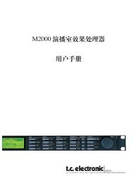
BUILT FOR POWERCORE<br />
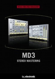
<strong>MD3</strong> STEREO MASTERING<br />
for POWERCORE<br />
USER MANUAL
E N GG L II S H<br />
<strong>TC</strong> SUPPORT INTERACTIVE<br />
The <strong>TC</strong> Support Interactive website is our online support and information center. At<br />
the site you can find answers to specific problems regarding <strong>TC</strong> products 24/7. All<br />
resolved problems are stored in a database searchable by product, category, keywords,<br />
or phrases.<br />
We constantly update the database and you will find the site to be a huge resource of<br />
information. Browse through our Q&A's and discover new aspects of your <strong>TC</strong> product.<br />
If you can't find an answer online, you have the option of submitting a question to our<br />
technical support staff who will then reply to you by e-mail. The <strong>TC</strong> Support Team is<br />
on constant alert to help you in any way they can.<br />
URL : www.tcsupport.tc<br />
CONTACT DETAILS<br />
Alternatively, you may contact the <strong>TC</strong> <strong>Electronic</strong> distributor in your area, or write to:<br />
International:<br />
<strong>TC</strong> ELECTRONIC A/S<br />
Customer Support<br />
Sindalsvej 34<br />
Risskov DK-8240<br />
Denmark<br />
USA:<br />
<strong>TC</strong> <strong>Electronic</strong>, Inc.<br />
5706 Corsa Ave. Suite 107<br />
Westlake Village, Ca. 91362<br />
www.tcelectronic.com<br />
© BY <strong>TC</strong> ELECTRONIC A/S 2004. ALL PRODUCT AND COMPANY NAMES ARE<br />
TRADEMARKS OF THEIR RESPECTIVE OWNERS. VST IS A TRADEMARK OF STEIN-<br />
BERG A.G., AUDIO UNITS IS A TRADEMARK OF APPLE, COMPUTER. ALL SPECIFI-<br />
CATIONS SUBJECT TO CHANGE WITHOUT NOTICE. ALL RIGHTS RESERVED. <strong>TC</strong><br />
ELECTRONIC IS A <strong>TC</strong> GROUP COMPANY.
TABLE OF CONTENTS<br />
TABLE OF CONTENTS . . . . . . . . . . . . . . . . . . . . . . . . . . . . . . . . . . . . . . . . . . . . . .1<br />
INTRODUCTION TO MD-3 Stereo Mastering Package . . . . . . . . . . . . . . . . . . . . . . . .2<br />
GETTING STARTED . . . . . . . . . . . . . . . . . . . . . . . . . . . . . . . . . . . . . . . . . . . . . . . .3<br />
SYSTEM REQUIREMENTS . . . . . . . . . . . . . . . . . . . . . . . . . . . . . . . . . . . . . . . . . . .3<br />
PROCESSING DELAY . . . . . . . . . . . . . . . . . . . . . . . . . . . . . . . . . . . . . . . . . . . . . . .4<br />
POWERCORE REQUIRED . . . . . . . . . . . . . . . . . . . . . . . . . . . . . . . . . . . . . . . . . . . .4<br />
PARAMETER OVERVIEW . . . . . . . . . . . . . . . . . . . . . . . . . . . . . . . . . . . . . . . . . . . .5<br />
MAIN PAGE . . . . . . . . . . . . . . . . . . . . . . . . . . . . . . . . . . . . . . . . . . . . . . . . . . . . .6<br />
EXPANDER COMPRESSOR . . . . . . . . . . . . . . . . . . . . . . . . . . . . . . . . . . . . . . . . . . .8<br />
EQ PAGE . . . . . . . . . . . . . . . . . . . . . . . . . . . . . . . . . . . . . . . . . . . . . . . . . . . . . . .9<br />
NORMALIZER PAGE . . . . . . . . . . . . . . . . . . . . . . . . . . . . . . . . . . . . . . . . . . . . . .13<br />
EXPANDER PAGE . . . . . . . . . . . . . . . . . . . . . . . . . . . . . . . . . . . . . . . . . . . . . . . .14<br />
COMPRESSOR PAGE . . . . . . . . . . . . . . . . . . . . . . . . . . . . . . . . . . . . . . . . . . . . . .16<br />
OUTPUT PAGE . . . . . . . . . . . . . . . . . . . . . . . . . . . . . . . . . . . . . . . . . . . . . . . . . .18<br />
BRICKWALL LIMITER . . . . . . . . . . . . . . . . . . . . . . . . . . . . . . . . . . . . . . . . . . . . .20<br />
PRESET MANAGEMENT . . . . . . . . . . . . . . . . . . . . . . . . . . . . . . . . . . . . . . . . . . . .22<br />
QUICK PRESET COMPARISSON . . . . . . . . . . . . . . . . . . . . . . . . . . . . . . . . . . . . . .22<br />
MD 3 / 1<br />
E NN GG L II S HH
E N GG L II S H<br />
Introduction<br />
<strong>TC</strong> <strong>Electronic</strong> is proud to introduce the MD-3 Stereo package for <strong>TC</strong> <strong>PowerCore</strong>. This<br />
package includes both our MD-3 Multi-Band Dynamics and BrickWall Limiter algorithms,<br />
the finest stereo mastering tools from our award winning System 6000.<br />
MAIN FEATURES<br />
• Four band Parametric EQ (Dual Mono capability)<br />
Normalizer<br />
Three band Exp/Comp/Lim<br />
MS Encode/Decode<br />
Sample accurate BrickWall Limiter<br />
MD-3<br />
The MD-3 plug-in features both Dual Mono and Stereo dynamics processing in three<br />
frequency bands. It's pristine signal-path uses 48 bit processing.<br />
Make-up gain can be applied automatically or manually, so the algorithm can be setup<br />
to do everything from strictly limiting to level maximization.<br />
By offering a true side-chain split structure, <strong>MD3</strong> is also capable of demanding mono<br />
material compression/limiting on two separate channels , not found in other multiband<br />
dynamics processors.<br />
Look-ahead delay may be used for improved peak handling and low distortion operation.<br />
Used for mastering,<strong>MD3</strong> can be regarded as a high-end mastering tool. M and S components<br />
of a stereo signal can be processed separately and provide even more control<br />
making full use of the Spectral Stereo Enhancer.<br />
I/O page / Head Room<br />
In case you are working with very hot signal levels in your audio application, you might<br />
experience clipping of the input of the MD-3 or BrickWall limiter algorithm.<br />
In that case, we recommend that you lower the output level of the previous plug-in ,<br />
or turn down your input channel or send level.<br />
2/ MD 3
If this does not help, you can use the build-in headroom parameter on the plug-in I/O<br />
page, to get an additional head room. Please be aware that this results in a loss of bit<br />
resolution.<br />
Setting the Head Room parameter to a value different from 0 dB will change two<br />
gains: the native input gain is set to reduce the signal level,<br />
while the gain at the input to the 48 bit algorithm is set to make up that reduction.<br />
The advantage of this is that any of the algorithm parameters (especially thresholds)<br />
will affect the signal in the same way, independent of the headroom setting.<br />
The disadvantage is that some of the lower bits are lost in the 24 bit path to the algorithm.<br />
On the other hand, the same loss would happen when you would reduce the<br />
signal via an input level parameter.<br />
Getting Started<br />
SYSTEM REQUIREMENTS<br />
The Plug-In requires POWERCORE PCI or POWERCORE FIREWIRE version 1.9 or<br />
later to be available in your system.<br />
MAC OS X<br />
<strong>PowerCore</strong> PCI/Element or <strong>PowerCore</strong> FireWire running system 1.9 or later<br />
G4 or G5 (800 MHz or faster)<br />
256 MB RAM (512 MB or more recommended)<br />
Mac OS X (10.2.6 or higher)<br />
Any VST or AudioUnits compatible host application<br />
System must meet requirements of the host application<br />
Internet connection for product activation<br />
WINDOWS<br />
<strong>PowerCore</strong> PCI or FireWire running system 1.9 or later<br />
Pentium III 1GHz or faster<br />
256 MB RAM (512 MB or more recommended)<br />
Windows XP<br />
Any VST-compatible application<br />
System must meet requirements of the host application<br />
Internet connection for product activation<br />
MD 3 / 3<br />
E NN GG L II S HH
E N GG L II S H<br />
PROCESSING DELAY<br />
In addition to the typical latency delay associated with DSP Plug-Ins, MD-3 and<br />
BrickWall Limiter also has an internal processing delay that will increase the latency.<br />
Using a larger look-ahead delay in MD-3 will result in additional latency being introduced.<br />
Most host applications feature automatic plug-in delay compensation that will<br />
adjust for any latency automatically. Check with your host application software manufacturer<br />
whether plug-in delay compensation is supported.<br />
POWERCORE REQUIRED!<br />
The MD-3 Stereo Mastering package requires a <strong>PowerCore</strong> device to run on your system.<br />
SCROLL WHEEL SUPPORT<br />
If you are using a host application that supports this feature, all of the MD-3 and<br />
BrickWall Limiter parameters support scrolling on both Windows XP and Mac OS X.<br />
Simply roll your mouse over a knob and use the Scroll Wheel to increment / decrement<br />
the associated parameter.<br />
TOOLTIPS<br />
If you are just getting started with the MD-3 Stereo Mastering Package and you want<br />
to know what all the parameters do, press the question mark Icon to activate the<br />
tooltip function.When activated, moving the mouse over the different parameters will<br />
display information about the parameter functionality. Of course you can disable the<br />
tooltips, as soon as you know your way around.<br />
DISPLAY DISABLED<br />
Should your <strong>PowerCore</strong> be fully loaded and there is not enough free processing on<br />
your DSPs, the plug-in will come up in a disabled state. Should this occur, it is<br />
advised to remove the Plug-In from the mix.<br />
The User Group - Assign key<br />
You can group your own set of most important parameters into a user group at the bottom<br />
of the plug-in for having a better overview, without having to switch pages.<br />
By pressing the Control Group Selector Up key you enter the User group. In this group<br />
you can assign any parameter to any Control field in the group. The User Control<br />
group is stored with a preset.<br />
• Press the Link key.<br />
• Select the Control field you wish to link a parameter to, by pressing the field.<br />
• Press the parameter you wish to link to the selected Control field.<br />
4/ MD 3
PARAMETER OVERVIEW<br />
The MD-3 is a 3-band 2-Channel Dynamics processing algorithm. The algorithm contains:<br />
Stereo four band precision EQ (Linked or Dual-mono operation)<br />
Stereo 3-band compression with linked or separate SideChains<br />
MS-Encode/Decode at the Input and Output<br />
The MD-3 will run at sample rates up to 96kHz<br />
Signal flow through the algorithm:<br />
MD 3 / 5<br />
E NN GG L II S HH
E N GG L II S H<br />
MAIN PAGE<br />
6/ MD 3<br />
The MD-3 algorithm occupies:<br />
Sample Rate PCI/Element <strong>PowerCore</strong> FW<br />
@ 44.1 khz 40 % of 1 DSP<br />
@ 48 khz 44% of 1 DSP<br />
@ 88.2 khz 92 % of 1 DSP 72 % of 1 DSP<br />
@ 96 khz 100% of 1 DSP 79 % of 1 DSP<br />
* Subject to change
Inlevel Left and Inlevel Right<br />
Range: Off to 0dB<br />
-40dB in 0.5dB steps<br />
Sets the Input level for the two Input channels<br />
Input Mode<br />
Range: Stereo, Dual Mono, MS Linked, MS Unlink.<br />
Selects the Input mode.<br />
Stereo<br />
In Stereo Mode the Expander/Compressor section of the algorithm uses one common<br />
SideChain for both Left and Right channels and the EQ section is linked.<br />
Please note that when coming from e.g. Dual Mono mode EQ settings from the Left<br />
channel will be copied to the right channel.<br />
Dual Mono<br />
In Dual Mono mode the Expander/Compressor section of the algorithm uses separate<br />
SideChains for the Left and Right Channel and they can be operated individually.<br />
Linked<br />
In the MS Linked mode the MS Encoder is activated and the Expander/Compressor<br />
section of the algorithm uses one common SideChain for both Left and Right channels.<br />
EQ is unlinked.<br />
MS Unlinked<br />
In the MS Unlinked mode the MS Encoder is activated and the Expander/Compressor<br />
section of the algorithm uses separate SideChains for the Left and Right Channels. EQ<br />
is unlinked.<br />
NOTE : When a mono signal is processed, only the left channel of the algorithm is<br />
active<br />
Output Mode<br />
Range: Left/Right, MS<br />
Left/Right : Straight Output without MS Decode.<br />
MS : MS decode before the limiter section.<br />
DC block<br />
Range: Off, On<br />
The DC block is a Lo Cut filter used to remove potential DC-noise at 2Hz.<br />
MD 3 / 7<br />
E NN GG L II S HH
E N GG L II S H<br />
EXPANDER/COMPRESSOR SETUP<br />
Lo Xover<br />
Range: Off, 25, 32, 40, 50, 63, 80Hz ......... 16kHz<br />
Sets the Cross-over frequency between the Lo and Mid Expander/Compressor bands for<br />
the two channels.<br />
Hi Xover<br />
Range: Off, 25, 32, 40, 50, 63, 80Hz ......... 16kHz<br />
Sets the Cross-over frequency between the Mid and the Hi Expander and Compressor<br />
bands for the two channels.<br />
NOTE : The Lo Xover value can not be higher than the Hi Xover.<br />
Crest<br />
Range: Peak, 6, 10, 12, 14, 16, 20, 24, RMS<br />
Select compression method between RMS and PEAK for all three bands. The dB steps<br />
between RMS and Peak are number of dBs needed for a peak-value to override RMS<br />
measurement and can be perceived as a Threshold setting.<br />
Example:<br />
If the Crest parameter is set to 6dB, the Compressor will respond to RMS values and<br />
to peaks 6dB higher than the current RMS value.<br />
Auto Gain<br />
Range: Off/On<br />
Switches the Automatic Make-up gain on or off for the Compressor bands. When set to<br />
on the gain for each band is adjusted according to Threshold and Ratio settings. When<br />
set to off, no automatic gain adjustments are performed<br />
Nominal Delay<br />
Range: 0 to 15ms<br />
2ms in 0.5 ms steps<br />
Sets the nominal Delay of the signal compared to the Sidechain signal. This is also<br />
known as "Look ahead delay", enabling the compressor section to become more<br />
responsive to the incoming signal thereby performing a more precise compression.<br />
Reference Level<br />
Range: -24dBFS to 0dBFS in 0.5dB steps<br />
This parameter sets the reference level in the algorithm.<br />
The reference level is the level at which the Compressor Threshold parameters will<br />
start operating when set to 0dB.<br />
8/ MD 3
EQ Page<br />
INTRODUCTION<br />
This digital EQ features a four-band parametric EQ with high- and low-pass filters<br />
switchable between Notch, Parametric, Shelving and Cut filters. The needle sharp<br />
notch filter has a range down to 0.01 octave and the shelving filters has a variable<br />
slope, ranging from gentle 3 dB/oct over 6 and 9 to 12dB/oct. Cut filters are switchable<br />
between 12dB/oct maximum flat amplitude (Butterworth) or flat group delay<br />
(Bessel) types. The parametric equalizer features a natural and well defined bandwidth<br />
behavior at all gain and width settings:<br />
BASIC OPERATION<br />
Press keys Lo, Mid1, Mid2 and Hi to activate/deactivate the EQ bands.<br />
Select Freq, Gain, Type or Lo/Hi to access all four parameters on individual bands.<br />
Press Bypass EQ to bypass all four bands.<br />
MD 3 / 9<br />
E NN GG L II S HH
E N GG L II S H<br />
TYPE SELECTOR<br />
Press Type and use faders 1-4 to select filter types.<br />
For Lo and Hi filters select between filter types:<br />
Parametric, Notch, Shelve and Cut.<br />
For Mid 1 and Mid 2 filters select between filter types:<br />
Parametric and Notch.<br />
Parametric Filter - Broad type<br />
Shelving Filter<br />
10 / MD 3
Notch Filter - Narrow Type<br />
Cut Filter - Bessel type<br />
Cut Filter - Butterworth type<br />
MD 3 / 11<br />
E NN GG L II S HH
E N GG L II S H<br />
Freq<br />
Press Freq and use Faders 1 to 4 to adjust frequence for each of the four bands.<br />
Range - Lo band : 20Hz to 20kHz<br />
Range - Mid1 band : 20Hz to 20kHz<br />
Range - Mid2 band : 20Hz to 20kHz<br />
Range - Hi band : 20Hz to 40kHz<br />
Gain<br />
Press Gain and use Faders 1 - 4 to adjust gain for each of the four EQ bands.<br />
Range for the Parametric, Shelve and Cut type:<br />
Lo Gain : -12dB to +12dB<br />
Mid1 Gain : -12dB to +12dB<br />
Mid2 Gain : -12dB to +12dB<br />
Hi Gain : -12dB to +12dB<br />
Range for the Notch filter:<br />
Lo Gain : -inf; -97dB to 0dB<br />
Mid1 Gain : -inf; -97dB to 0dB<br />
Mid2 Gain : -inf; -97dB to 0dB<br />
Hi Gain : -inf; -97dB to 0dB<br />
TYPE<br />
Range for the Notch filter:<br />
Lo BW : 0.02oct to 1oct<br />
Mid1 BW : 0.02oct to 1oct<br />
Mid2 BW : 0.02oct to 1oct<br />
Hi BW : 0.02oct to 1oct<br />
Range for the Parametric filter:<br />
Lo BW : 0.1oct to 40kHz<br />
Mid1 BW : 0.1oct to 40kHz<br />
Mid2 BW : 0.1oct to 40kHz<br />
Hi BW : 0.1oct to 40kHz<br />
Range for the Shelve filter:<br />
Lo BW : 3dB/oct to 12dB/oct<br />
Hi BW : 3dB/oct to 12dB/oct<br />
12 / MD 3<br />
Range for the Cut filter:<br />
Lo BW : Bessel or Butterworth<br />
Hi BW : Bessel or Butterworth<br />
Bandwidth/Q - Key-Values:<br />
BW Q<br />
0.5 - 2.87<br />
0.7 - 2.04<br />
1.0 - 1.41
Normalizer<br />
When using the EQ section (located just before the Normalizer) the gain might have<br />
been increased or decreased. The Normalizer is used to optimize the gain<br />
before hitting the Expander/Compressor section.<br />
Trim Left and Trim Right<br />
Range: -6 to +18dB in 0.1dB steps<br />
Level parameter between the EQ and Exp/Comp section.<br />
When Input Mode is set to Stereo the parameters will be linked.<br />
Soft clip<br />
Range: +5dB; Off<br />
The Soft clipper is placed between the Normalizer and Exp/Comp section. By enabling<br />
the Soft clipper you are able to reduce potential overshoots.<br />
MD 3 / 13<br />
E NN GG L II S HH
E N GG L II S H<br />
Expander<br />
Pressing Threshold, Range, Ratio, Attack and Release keys will immediately assign Lo,<br />
Mid, Hi and Master values for these parameters to Faders 1-4. Press the L/R key to<br />
see all parameters at the same time.<br />
Threshold parameters<br />
Range: -50dB to 0dB (in 0.5dB steps)<br />
When the signal drops below the set Threshold value the Expander will be activated.<br />
Range<br />
Range: -40dB to 0dB in 0.5dB steps<br />
The Range parameter sets the Max attenuation relative tp the Ref level setting.<br />
Example: With a Ref Level setting of -6 dB and Range set to -10 the max attenuation<br />
can be -16dB.<br />
Ratio parameters<br />
Range: Off to Infinity<br />
The Ratio of the Gain Reduction.<br />
Example: If the signal drops 1 dB below the Threshold with a Ratio set to 1:3 the<br />
actual attenuation will be 3dB.<br />
14 / MD 3
Attack<br />
Range: 0.3 to 100ms (Exponential)<br />
The Attack time is the time the Expander uses to generate the gain reduction specified<br />
by the Ratio parameter.<br />
Release<br />
Range: 20ms to 7sec. (Exponential)<br />
The time it takes for the Expander to release its attenuation of the signal when the<br />
signal exceeds the Threshold.<br />
Meter Zoom<br />
Press to zoom on the range of the Gain Reduction meters.<br />
L/R<br />
Press to view all algorithm parameters at the same time.<br />
MD 3 / 15<br />
E NN GG L II S HH
E N GG L II S H<br />
Compressor Page<br />
Pressing Threshold, Gain, Ratio, Attack and Release keys will immediately assign Lo,<br />
Mid, Hi and Master values for these parameters to Faders 1-4. Press the L/R key to<br />
see all parameters at the same time.<br />
Threshold<br />
Range: -25dB to 20dB (in 0.5dB steps)<br />
Relates to the Ref.Level setting.<br />
General explanation - when the Input signal exceeds the Threshold value the<br />
Compressor starts to reduce the dynamic content of the signal according to the set<br />
Ratio.<br />
Gain<br />
Range: Off, -18dB to 12dB in 0.5dB steps.<br />
<strong>Manual</strong> Makeup-gain for each compression band.<br />
Where the Auto Gain control in the Main page compensates for the total gain reduction<br />
caused by the Compressor, the Gain controls in the Compressor pages are used as<br />
additional gain controls on the individual bands.<br />
16 / MD 3
Ratio<br />
Range: Off to Infinity<br />
Specifies the Ratio of the performed compression.<br />
Example: With a Ratio setting of 2:1 the compressor will reduce every 2dB above the<br />
Threshold point to only 1dB.<br />
Attack<br />
Range: 0.3 to 100ms<br />
The Attack time is the time the Compressor uses to reach the gain reduction specified<br />
by the Ratio parameter.<br />
Example: If the Input signal increases by 4dB above the set Threshold with a Ratio<br />
set to 2:1 and the Attack time set to 20ms, the Compressor will use 20ms to reach a<br />
Gain reduction of 2dB.<br />
Release<br />
Range: 20ms to 7s<br />
The fallback time. The time it takes for the Compressor to release the attenuation of<br />
the signal.<br />
Meter Zoom<br />
Press to zoom on the range of the Gain Reduction meters.<br />
L/R<br />
Press to view all algorithm parameters at the same time.<br />
MD 3 / 17<br />
E NN GG L II S HH
E N GG L II S H<br />
Output page<br />
FULL RANGE LIMITER<br />
Soft clip<br />
Range: -6dB to 0 dB in 1-dB-steps; +3dB; off.<br />
Soft clipper after the Compressor.<br />
Threshold is relative to 0dBFS - not to the Ref Level.<br />
Threshold<br />
Threshold is relative to 0dBFS - not to the Ref Level.<br />
Range: -12 to +3 dB<br />
-6 to + 3 in 0.1dB increments<br />
-12 to -6 in 0.5dB increments<br />
18 / MD 3
Release<br />
Range: 20ms to 7sec<br />
Release time for the Limiter.<br />
Ceiling<br />
Range: 0 to -0,10dB in 0.01dB steps.<br />
Fine-tuning parameter setting the Ceiling for the Limiter.<br />
This parameter prevents the Output signal from ever exceeding the adjusted<br />
Threshold. It can be used to "hide" overloads to downstream<br />
equipment, but it does not remove the distortion associated with an over.<br />
TRIM LEVELS<br />
Trim L<br />
Range: 0 to -12dB in 0.1dB steps<br />
Left channel Output level trim after the Compressor and Output mode parameter (M/S)<br />
and before the Limiter section.<br />
Trim R<br />
Range: 0 to -12dB in 0.1dB steps<br />
Right channel Output level trim after the Compressor and Output mode parameter<br />
(M/S) and before the Limiter section.<br />
Output Fader<br />
Range: Off to 0dB (-40 in 0.5dB steps)<br />
Output fader for both Outputs.<br />
Balance<br />
Range: -6dBL to -6dBR<br />
Changes the Output balance between the Left and Right channel.<br />
COMPARE key<br />
Due to the difference in level, "in-circuit" and "out-of-circuit" comparisons are often<br />
difficult to make using the BYPASS key. Use the Compare Level parameter to compensate.<br />
Press to activate compare function.<br />
Compare Level<br />
Range: -20 to 0dB<br />
Bypass Lim.<br />
Press to bypass the Limiter section.<br />
MD 3 / 19<br />
E NN GG L II S HH
E N GG L II S H<br />
BRICKWALL LIMITER<br />
GETTING STARTED<br />
The BrickWall limiter cannot prevent destruction of dynamic range from happening at<br />
earlier stages in the production process, but it can get rid of the signals we know are<br />
going to get distorted in consumer CD players, radio processors or data reduction<br />
codecs.<br />
Precision in Level and Time<br />
The BrickWall limiter operates with extended precision in both level (48 bit throughout)<br />
and time (5 times oversampling). Double precision calculations are always used,<br />
while hyper-precision in limiter timing can be turned<br />
on or off using the Upsample key.<br />
Level meters are always upsampled in order to identify intersample and 0dBFS+ peaks<br />
on Inputs as well as Outputs. The meter scale is extended to +3dBFS because excessive<br />
level normally falls between 0 and +3dBFS, and<br />
most consumer equipment already exhibits severe distortion at +0.5 dBFS.<br />
We recommend using the BrickWall limiter in Upsample mode. However, if you wish to<br />
just limit the signal based on sample by sample values like a normal digital limiter,<br />
the function can be turned off. When turned off the limiter does<br />
not protect against 0dBFS+ peaks from occurring.<br />
20 / MD 3
Limiter Time constants<br />
The Limiter employs adaptive time constants to combat distortion at low frequencies<br />
while maintaining quick adoption to occasional peaks.<br />
A manual Release time can be set if the Auto Release key is turned off. We recommend<br />
using the Auto setting with Release set at Default. If quick recovery and loudness<br />
is an issue, move the Release setting in the Fast direction.<br />
Processing of very sensitive material might sound better with Release settings in the<br />
Slow direction.<br />
Absolute Bit Transparency<br />
Whenever the BrickWall limiter is not attenuating the signal, it is passed completely<br />
unaffected, transparent to the 24th bit. Consequently, the BrickWall limiter may be<br />
used to remove 0dBFS+ peaks on already mastered and finally dithered material.<br />
When the Limiter is bit transparent, a green indicator next to the Threshold control<br />
lights up.<br />
Input and Output gain controls have 0.1dB increments, but snap to bit shifts at 0, 6,<br />
12, 18 and 24dB settings. When a bit shift value is selected, a green indicator is lit<br />
on the screen. Bit transparency from Input to Output is obtained when Input Gain and<br />
Output Fader hit these values and sum to 0dB, e.g. Input/Output 0/0dB, -6/+6 dB, -<br />
12/+12dBetc.<br />
Bit Pattern Transparency<br />
When only bit shift gain settings are used on Input and Output, bit patterns remain<br />
unchanged through the algorithm, but can be shifted up (in the MSB direction) or<br />
down (in the LSB direction) as desired. E.g. Input/Output +6/0 (one up), 0/-12 (two<br />
down).<br />
Linking<br />
The two channels BrickWall limiters can be operated independently or linked. If pronounced<br />
limiting is performed on stereo material, linking should be considered to<br />
avoid L/R image shifts. If only mild and occasional limiting is<br />
being done, un-linked operation even on stereo material<br />
may sound the best.<br />
MD 3 / 21<br />
E NN GG L II S HH
E N GG L II S H<br />
PRESET MANAGEMENT<br />
<strong>TC</strong>'s comprehensive file based preset architecture makes archiving presets a simple<br />
process.This allows you to organize your presets the way you find most comfortable for<br />
your workflow, and to exchange presets with other users, no matter the platform or<br />
application. Presets are saved as discrete files on your hard drive. Once a preset is<br />
saved into the default location, it will automatically appear in the 'File' menu every<br />
time you use the Plug-In.The files can then be organized into subfolders, where you<br />
can delete, rearrange or create your own sub-folders to accommodate your needs.<br />
NOTE: A folder will not appear in the Preset File Menu unless the folder has at least<br />
one preset inside!<br />
PRESET FILE MENU<br />
Pressing the 'File' button will open the Plug-In's File menu. The following options are<br />
available from the File menu.<br />
LOADING A PRESET<br />
By selecting 'Load', you can navigate to any folder on the system that you have read<br />
access to, including any shared folder. By default, these will be loaded from the<br />
default location for MD-3 and BrickWall presets. Only presets located in the default<br />
file location will appear in the MD-3 and BrickWall Limiter pop-up preset menu.<br />
NAMING A PRESET<br />
Double click on the name field<br />
Type in the new name<br />
Press Enter<br />
SAVING A PRESET<br />
By selecting 'Save', you can save your preset to any folder on the system that you have<br />
write access to, including any shared folder. By default, presets are saved to the<br />
default location for the MD-3 and BrickWall Limiter presets.<br />
QUICK PRESET COMPARISON<br />
The 'A / B' function of MD-3 and BrickWall Limiter allows for a quick comparison of<br />
two different settings.<br />
Select 'Store' and then 'A' or 'B' to save a setting into either the 'A' or 'B' memory.After<br />
setting up both an 'A' and a 'B' setting, you can simply select either 'A' or 'B' to immediately<br />
compare the two settings.As these are meant for a quick comparison, these<br />
settings are LOST when closing the Plug-In! If you love your preset, we advise you to<br />
save it!<br />
DEFAULT PRESET LOCATIONS:<br />
The following locations will describe where you can find the MD-3 and BrickWall<br />
Limiter presets, which are stored in a folder unique to each plug-in:<br />
22 / MD 3
MAC OS X<br />
Files are stored in your user folder:<br />
~ \ Library \ Application Support \ <strong>TC</strong> <strong>Electronic</strong> \Presets\MD-3 Multiband Dynamics<br />
~ \ Library \ Application Support \ <strong>TC</strong> <strong>Electronic</strong> \Presets\BrickWall Limiter<br />
~ \ Refers to your user folder: Users \ Your Name<br />
WINDOWS<br />
Files are stored on the Windows OS hard drive.<br />
~ \ <strong>TC</strong>Works \ <strong>PowerCore</strong> \ <strong>TC</strong> <strong>Electronic</strong> \Presets\ MD-3 Multiband Dynamics<br />
~ \ <strong>TC</strong>Works \ <strong>PowerCore</strong>\ <strong>TC</strong> <strong>Electronic</strong> \Presets \BrickWall Limiter<br />
~ \ Refers to the path for your System Hard Drive \ Program Files<br />
To delete a file, simply move it to the 'Trash' or 'Recycle bin'.<br />
To create a new subfolder that appears in the Plug-In menu, simply create a new<br />
folder in the Plug-In folder that resides in the PRESETS folder of the MD-3 or<br />
BrickWall Limiter default preset location.<br />
NOTE: A folder will not appear in the Preset File Menu unless it has at least one preset<br />
inside.<br />
MD 3 / 23<br />
E NN GG L II S HH