A carbide drill designed with two asymmetrically angled cutting ...
A carbide drill designed with two asymmetrically angled cutting ...
A carbide drill designed with two asymmetrically angled cutting ...

Create successful ePaper yourself
Turn your PDF publications into a flip-book with our unique Google optimized e-Paper software.
By Herbert Kauper and Allen Poponick,<br />
Kennametal Inc.<br />
Walk<br />
On By<br />
A <strong>carbide</strong> <strong>drill</strong> <strong>designed</strong> <strong>with</strong> <strong>two</strong><br />
<strong>asymmetrically</strong> <strong>angled</strong> <strong>cutting</strong><br />
edges and three margins<br />
reportedly minimizes walking<br />
while extending tool life.<br />
All <strong>drill</strong>s walk. Although this adverse condition is<br />
typically associated <strong>with</strong> HSS <strong>drill</strong>s, out-of-roundness,<br />
deflection and poor cylindricality also result,<br />
to a lesser degree, when using a solid-<strong>carbide</strong> <strong>drill</strong>.<br />
The same forces that cause a <strong>drill</strong> to walk or pushoff<br />
also shorten tool life, especially when <strong>drill</strong>ing<br />
difficult-to-machine, exotic and expensive workpiece<br />
materials such as Inconel, Waspaloy and<br />
duplex stainless steel, commonly used for aerospace-<br />
and energy-industry parts. Wear quickly accelerates<br />
into tool chipping and then catastrophic <strong>drill</strong><br />
failure <strong>with</strong>in one or <strong>two</strong> holes of chipping occurrence,<br />
causing machine downtime and longer lead<br />
time for critical parts.<br />
Because of high material, labor and machine<br />
costs, the aerospace, energy and other major industries<br />
are demanding <strong>drill</strong>s that guarantee process<br />
security, consistent life for new and reconditioned<br />
JANUARY 2009 / VOLUME 61 / ISSUE 1<br />
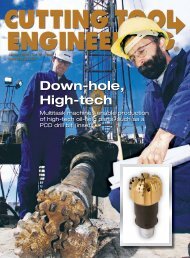
Kennametal<br />
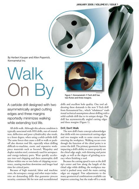
Figure 1: Kennametal’s Y-Tech <strong>drill</strong> has<br />
<strong>two</strong> flutes and three margins.<br />
<strong>drill</strong>s and excellent hole quality. One tool addressing<br />
these demands is the new Y-Tech <strong>drill</strong><br />
from Kennametal Inc., which “rebalances” traditional<br />
technical assumptions about <strong>drill</strong>ing <strong>with</strong> a<br />
solid-<strong>carbide</strong> <strong>drill</strong> due to its unique design. The<br />
<strong>drill</strong> has <strong>asymmetrically</strong> <strong>angled</strong> <strong>cutting</strong> edges<br />
and three margins (Figure 1).<br />
Drill, Don’t Walk<br />
The new <strong>drill</strong>’s basic concept acknowledges<br />
that <strong>drill</strong>s <strong>with</strong> <strong>two</strong> symmetrical <strong>cutting</strong> edges<br />
and <strong>two</strong> margins walk to some extent upon<br />
entering the workpiece. Walking occurs even<br />
though the function of the chisel point is to<br />
center the <strong>drill</strong>. The primary geometric factors<br />
impacting a <strong>drill</strong>’s ability to center properly are<br />
the chisel edge angle, web thinning and point<br />
angle, as well as the degree of grinding accuracy<br />
when finishing a tool.<br />
Because the <strong>cutting</strong> speed is zero at the <strong>drill</strong><br />
tip’s center and low along the length of the<br />
chisel edge while <strong>drill</strong>ing, the workpiece material<br />
is pushed away until the main <strong>cutting</strong><br />
edges are engaged. Fine adjustments to the<br />
many geometrical combinations available can<br />
improve centering, but the trade-off is a weak
chisel edge. Conversely, a robust chisel<br />
edge produces poor centering and high<br />
thrust but can tolerate high feed rates.<br />
Recent studies by the Institut für<br />
Produktionsmanagement, Technologie<br />
und Werkzeugmaschinen Technische<br />
(PTW), Universität Darmstadt, Germany,<br />
showed that as the chisel edge enters<br />
a workpiece, it creates a concave oval.<br />
This causes the <strong>drill</strong> to “swing” in a motion<br />
similar to a pendulum (Figures 2a<br />
and 2b). For ease of description, the <strong>drill</strong><br />
creates a triangular hole; the corners of<br />
the <strong>drill</strong> form the triangle’s points as the<br />
<strong>drill</strong> continues the pendulum motion<br />
created by the chisel edge.<br />
Coupled <strong>with</strong> the feed rate, the <strong>cutting</strong><br />
action is slightly comparable to helical<br />
interpolation, <strong>with</strong> the <strong>drill</strong> margins<br />
typically riding the lead of the chisel edge<br />
throughout the hole. The result is an outof-round<br />
hole <strong>with</strong> poor cylindricality<br />
and, at times, notable deflection from<br />
the centerline.<br />
Cutting forces are not equal per <strong>cutting</strong><br />
edge, so each <strong>cutting</strong> edge is at a<br />
slightly different plane as it follows the<br />
PTW<br />
Figures 2a and 2b: These illustrations show the pendulum motion and its impact on hole<br />
roundness caused by the concave oval that’s created as a conventional <strong>drill</strong>’s chisel edge<br />
enters a workpiece.<br />
pendulum. Geometric deviations found<br />
in the <strong>drill</strong> grinding process, such as unequal<br />
hones on the <strong>cutting</strong> edges and<br />
symmetry errors, also contribute to creating<br />
asymmetric <strong>cutting</strong> forces.<br />
Material Matters<br />
High-tensile-strength workpiece materials<br />
compound the issues previously<br />
noted. However, the aerospace, energy,<br />
food processing and medical industries<br />
desire parts made of those materials.<br />
When machining these materials, machine<br />
operators must lower feed rates,<br />
extending the time a <strong>drill</strong>’s chisel edge is<br />
pushing material away before the main<br />
<strong>cutting</strong> edges engage the workpiece. Such<br />
extreme wear on the chisel edge further
Walk On By (continued)<br />
reduces a <strong>drill</strong>’s ability to center for subsequent<br />
holes, thereby increasing the pendulum<br />
motion.<br />
Workhardening and elasticity increase<br />
<strong>cutting</strong> forces and therefore the<br />
risk of <strong>drill</strong> push-off when <strong>drill</strong>ing hightensile-strength<br />
materials. As a result,<br />
hole-roundness errors become more pronounced<br />
in these materials.<br />
Typical tool wear when <strong>drill</strong>ing these<br />
materials includes chipping of the chisel<br />
edge, <strong>cutting</strong> edge (often caused as the<br />
<strong>drill</strong> is retracted) and the margin below<br />
the <strong>cutting</strong> edge. All contribute to reducing<br />
the number of times a <strong>drill</strong> can<br />
be reground, reducing <strong>drill</strong> life and the<br />
tool’s overall value.<br />
Other factors affecting hole quality are<br />
toolholding, machine rigidity and fixturing.<br />
However, these factors can rarely rectify<br />
errors starting at the chisel edge.<br />
Reconsidering Balance<br />
Balance is a state of equilibrium. Although<br />
symmetrically <strong>designed</strong>, conventional<br />
<strong>drill</strong>s tend to create and perpetuate<br />
Kennametal<br />
A chipped margin land, such as the one<br />
shown on this conventional solid-<strong>carbide</strong><br />
<strong>drill</strong>, reduces the number of times a solid<strong>carbide</strong><br />
<strong>drill</strong> can be reground.<br />
unbalanced <strong>cutting</strong> forces in the cut that<br />
cannot be controlled. The Y-Tech <strong>drill</strong><br />
redefines balance from an aesthetic design<br />
to a controlled function of the <strong>drill</strong>ing<br />
process.<br />
The new <strong>drill</strong>’s design is not symmetrical.<br />
One of the <strong>two</strong> <strong>cutting</strong> edges is<br />
<strong>asymmetrically</strong> <strong>angled</strong> above the <strong>drill</strong>’s<br />
centerline. This slightly leading edge<br />
creates an overriding, one-directional<br />
force.<br />
Counteracting this force is a guiding<br />
margin behind the lead <strong>cutting</strong> edge.<br />
This controlled <strong>cutting</strong> force is directed<br />
against the guiding margin counterforce,
Glossary<br />
The following Terms were extracted from ANSI B94.11-M-1979, “Twist Drills—<br />
Straight Shank and Taper Shank, Combined Drills and Countersinks.”<br />
chisel edge<br />
Edge at the end of the web that<br />
connects the <strong>cutting</strong> lips.<br />
chisel edge angle<br />
Angle included between the chisel edge<br />
and the <strong>cutting</strong> lip as viewed from the<br />
end of the <strong>drill</strong>.<br />
lips<br />
Cutting edges of a 2-flute <strong>drill</strong> that<br />
extend from the chisel edge to the<br />
periphery. On core <strong>drill</strong>s, the lips are<br />
the <strong>cutting</strong> edges that extend from the<br />
bottom of the chamfer to the periphery.<br />
margin<br />
Cylindrical portion of the land that is<br />
not cut away to provide clearance.<br />
ensuring the <strong>drill</strong> maintains the tool’s diameter<br />
throughout the cut. Any latent<br />
side-to-side forces are supported by <strong>two</strong><br />
traditionally placed margins.<br />
To minimize the walking and pendulum<br />
motion, the new <strong>drill</strong> has a chisel<br />
edge that enables effective self-centering<br />
and a relatively short transition time<br />
from the chisel to the <strong>cutting</strong> edges. In<br />
addition, the <strong>drill</strong> is suited for the low<br />
feed rates generally used in <strong>drill</strong>ing hightemperature<br />
alloys because the <strong>cutting</strong><br />
edges have a light or medium hone that<br />
ensures the <strong>drill</strong> is <strong>cutting</strong> <strong>with</strong>out workhardening.<br />
Eliminating the pendulum motion<br />
not only improves hole quality but also<br />
reduces wear on the chisel edge, <strong>cutting</strong><br />
lips and the corner of the <strong>drill</strong>, substantially<br />
improving tool life. A producer of<br />
power turbines made from ASTM A 681<br />
D3 (DIN X210Cr12) material reported a<br />
60 percent improvement in tool life and<br />
elimination of retraction damage caused<br />
point<br />
Cutting end of the <strong>drill</strong>, comprised of<br />
the ends of the lands, the web and the<br />
lips. It resembles a cone, but it departs<br />
from a true cone to furnish clearance<br />
behind the <strong>cutting</strong> lips.<br />
point angle<br />
Angle included between the lips<br />
projected upon a plane parallel to the<br />
<strong>drill</strong> axis and parallel to the <strong>cutting</strong> lips.<br />
web thinning<br />
Operation of reducing the web<br />
thickness at the point to reduce <strong>drill</strong>ing<br />
thrust.<br />
Comparison of <strong>drill</strong> performance when <strong>drill</strong>ing duplex stainless steel<br />
in a laboratory test.<br />
Y-Tech <strong>drill</strong> Conventional solid-<strong>carbide</strong> <strong>drill</strong><br />
Roundness 13µm 52µm<br />
Cylindricality 19µm 117µm<br />
Straightness 20µm 23µm<br />
Parallelism 20µm 36µm<br />
Inclination 4µm 33µm<br />
Kennametal<br />
by hole shape errors, such as spirals and<br />
corner chipping.<br />
Drills want to walk when entering a<br />
workpiece, but <strong>drill</strong>s that rebalance traditional<br />
technical assumptions can provide<br />
improved hole quality required for<br />
critical parts. CTE<br />
About the Authors: Herbert Kauper is<br />
senior product engineer, solid-<strong>carbide</strong><br />
<strong>drill</strong>s, and Allen Poponick is manager,<br />
global machine technology-holemaking<br />
for Kennametal GmbH & Co. KG, Fürth,<br />
Germany. For more information about the<br />
company’s <strong>cutting</strong> tools, call Kennametal<br />
Inc., Latrobe, Pa., at (800) 446-7738 or visit<br />
www.kennametal.com.<br />
www.ctemag.com<br />
For more information, visit<br />
“Articles Archive Index” and select<br />
the “Holemaking” category.<br />
CUTTING TOOL ENGINEERING Magazine is protected under U.S. and international copyright laws.<br />
Before reproducing anything from this Web site, call the Copyright Clearance Center Inc. at (978) 750-8400.