Open pit mine rockfall protection - InfoMine
Open pit mine rockfall protection - InfoMine
Open pit mine rockfall protection - InfoMine

Create successful ePaper yourself
Turn your PDF publications into a flip-book with our unique Google optimized e-Paper software.
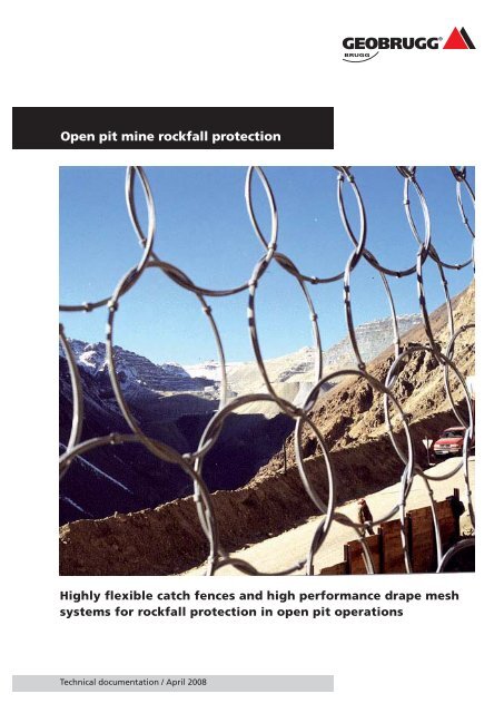
<strong>Open</strong> <strong>pit</strong> <strong>mine</strong> <strong>rockfall</strong> <strong>protection</strong><br />
Highly fl exible catch fences and high performance drape mesh<br />
systems for <strong>rockfall</strong> <strong>protection</strong> in open <strong>pit</strong> operations<br />
Technical documentation / April 2008
Rockfall barriers / technical documentation / April 2008<br />
Highly fl exible catch fences and high<br />
performance drape mesh systems for<br />
<strong>rockfall</strong> <strong>protection</strong> in open <strong>pit</strong> operations<br />
2<br />
R. Coates, G, Bull & F. J. Glisson Rock Engineering, Perth, Australia<br />
A. Roth, MSc. Eng. ETH Geobrugg AG, Protection Systems<br />
Romanshorn, Switzerland<br />
andrea.roth@geobrugg.com<br />
ABSTRACT<br />
Rockfall hazards in open <strong>pit</strong> applications mainly occur in steep open <strong>pit</strong> walls<br />
due to aggressive <strong>pit</strong> design, in fl at walls without berms while following shallow<br />
dipping ore bodies or locally on batter level. Areas with high damage<br />
potential such as decline portals or haulage ramps are especially hazardous.<br />
Dangers from falling rocks have to be reduced as much as possible. The <strong>protection</strong><br />
systems to cope with such hazards from the manufacturer Geobrugg<br />
which are described in this paper are highly fl exible and consist of high-tensile<br />
steel components. They are fi eld tested and are thus rated with a certain<br />
energy absorption capacity. In order to get impact velocities and energies, a<br />
<strong>rockfall</strong> simulation is run, utilising actual slope characteristics. This study deals<br />
with three case studies of <strong>rockfall</strong> <strong>protection</strong> systems recently implemented<br />
in Western Australia. The fi rst study describes a portal <strong>protection</strong> fence, the<br />
second one a ramp <strong>protection</strong> fence and the third one a high-performance<br />
drape system with impact section.<br />
INTRODUCTION<br />
From a global point of view <strong>rockfall</strong>s in open <strong>pit</strong> <strong>mine</strong>s mainly occur in steep<br />
open <strong>pit</strong> walls due to aggressive <strong>pit</strong> design or in bermless fl at walls while<br />
following shallow dipping ore bodies. Locally, <strong>rockfall</strong>s can take place on a<br />
batter level, with rocks falling out of the crest or the batter itself and reaching<br />
the next berm. In areas with a high danger potential such as portals,<br />
ramps, escape ways or exhausts, adequate measures have to be taken to<br />
reduce this risk to the work force and infrastructure. To cope with such<br />
hazard, different strategies and solutions can be implemented such as increasing<br />
berm width, building windrows, installing drape mesh or <strong>rockfall</strong><br />
barriers.<br />
Rockfall barriers have the advantage that if a stable foundation can be<br />
achieved, it is possible to effectively protect the area below the fence without<br />
the need to access onto the berm and without enlarging berms. This is<br />
mainly an interesting solution due to the fact that the overall angle is not<br />
affected or can be developed even steeper.
In order to be able to absorb energies in the range of 100 to several thousand<br />
kJ, it is necessary to install fl exible systems which gradually slow the rocks.<br />
Systems made of steel beams, sleepers or wire ropes are too stiff and thus<br />
induce large forces on the barrier during the impact. Due to the non-linear<br />
behaviour of fl exible <strong>rockfall</strong> barriers it is still not possible to design them<br />
on paper only; they still have to be tested “one on one”.<br />
The Swiss company Geobrugg is a leading supplier of <strong>rockfall</strong> <strong>protection</strong><br />
systems. Geobrugg gained experience in this fi eld over decades and has<br />
implemented hundreds of projects worldwide. The systems are all fi eld<br />
tested to deter<strong>mine</strong> the energy absorption capacity. The projects described<br />
here were installed by Rock Engineering, a ground support specialist company<br />
based in Perth.<br />
HIGH-TENSILE WIRE MESH<br />
The main element of the <strong>protection</strong> systems presented in this paper is the<br />
high-tensile chain-link mesh called TECCO. The mesh was developed by Geobrugg<br />
not only for static applications such as slope stabilization but for<br />
dynamic applications such as <strong>rockfall</strong> <strong>protection</strong> catch fences or for use as<br />
drape mesh as well. Both the static and dynamic performance of the mesh<br />
is proven by independent testing and applications.<br />
The mesh is made of high-tensile steel wire with a diameter of 4 mm and a<br />
tensile strength of 1770 MPa. Furthermore, this high-tensile wire has an<br />
excellent shear resistance. The mesh is diamond shaped and the wires at the<br />
selvedge are bent over and double twisted in such a way that this connection<br />
is as strong as the mesh itself. The mesh is produced in rolls and can be<br />
manufactured in widths up to 4 m and in tailor-made lengths.<br />
Figure 1: Geometry of the TECCO mesh<br />
3
Rockfall barriers / technical documentation / April 2008<br />
Table 1: Properties of the TECCO mesh<br />
G80/4 mm.<br />
Figure 2: WSL test facility Walenstadt,<br />
Switzerland<br />
4<br />
The static strength of the mesh was deter<strong>mine</strong>d in several laboratory testing<br />
programs by Torres (2002) at the University of Cantabria in Santander, Spain.<br />
The characteristics of the mesh are summarized in the table below:<br />
Clearance diameter 80 mm<br />
Wire diameter 4 mm<br />
Wire strength 1770 MPa<br />
Breaking load of a single wire 22 kN<br />
Tensile strength longitudinal 200 kN/m<br />
Tensile strength transversal 80 kN/m<br />
Weight 2.6 kg/m 2<br />
The tests of Torres (2002) further showed that there is no unravelling of the<br />
mesh once a wire failed. The tests were executed with a wire cut before<br />
testing the longitudinal strength. The test panel reached the same breaking<br />
loads with or without a cut wire.<br />
DYNAMIC TESTING OF THE MESH<br />
Several dynamic testing programs were carried out with the TECCO mesh on<br />
the test site of the Swiss Federal Institute of Forest, Snow and Landscape<br />
(WSL) in Walenstadt, Switzerland. The tests were executed by Geobrugg<br />
under supervision of WSL.
The testing facility consists of a steel frame construction with a crane installed<br />
above, with a remotely controlled release hook. In the test frame<br />
mesh panels of up to 4 m x 4 m can be put in place at a height of 5 m above<br />
ground. The tests are executed by using concrete boulders of different sizes<br />
released from a predeter<strong>mine</strong>d height (up to 65 m). Load cells are put in<br />
place under the frame and in the support ropes and two high-speed digital<br />
video cameras (250 frames/sec) record the impact sequence.<br />
Sennhauser (2002) executed several 50 kJ tests in late 2002 with a 2 m x 4 m<br />
panel of TECCO mesh. The impact energy was achieved by releasing smaller<br />
blocks from greater heights and also larger blocks from lower heights. The<br />
mesh stopped all the blocks and consequently showed the performance to<br />
easily absorb 50 kJ. The braking distance was in the order 1.5 m.<br />
The mesh did not show any damage. It was slightly deformed but there were<br />
no broken wires (see fi gure 4). Trials with multiple impacts in the same location<br />
of the mesh proved that the mesh is able to absorb at least two impacts<br />
of 50 kJ. Due to the very short braking distance, the forces in the support<br />
infrastructure get naturally quite high. But since these forces are known, it<br />
is possible to dimension ropes, posts and anchorage.<br />
Figure 3: 50 kJ test with a 2 m x 4 m<br />
panel of TECCO mesh.<br />
Figure 4: TECCO mesh after 50 kJ test<br />
5
Rockfall barriers / technical documentation / April 2008<br />
Figure 5: Impact testing on drape mesh<br />
Figure 6: Results obtained from drape<br />
testing<br />
6<br />
In addition to <strong>rockfall</strong> testing, Geobrugg also carried out fi eld tests with<br />
high performance drape mesh. In these trials TECCO mesh was used with<br />
wire diameters of 3 mm and 4 mm. In order to simulate the impact of a block<br />
into the mesh while sliding down behind the curtain, the mesh curtain was<br />
installed with an angle of 30° between the mesh and rock face and then the<br />
blocks were released into it (mirrored situation). Figure 5 shows such a test<br />
with 1730 kg free falling from 5 m into the drape mesh.<br />
By using this setup it was possible to deter<strong>mine</strong> the capacity of the mesh<br />
and this makes it possible to dimension a drape mesh system. The results are<br />
summarized in fi gure 6.<br />
Compared to other mesh products, the TECCO mesh has the advantage that<br />
its properties and performance are very well established (statically and<br />
dynamically).<br />
ROCKFALL SIMULATION<br />
In order to deter<strong>mine</strong> energy requirements in a specifi c case, special software<br />
is needed. The potential block sizes can be estimated by site visits but the<br />
impact velocities and kinetic energies have to be simulated. In the simulation<br />
described here the software is called ROCKFALL and was developed by Spang<br />
(1995) in Germany.<br />
Firstly, the cross section of the simulation has to be defi ned and split in slices<br />
with different properties such as dynamic and static friction, damping factors,<br />
rolling resistance and surface roughness. All these values are defi ned probabilistically<br />
with standard deviations. The blocks can be chosen as spheres or,<br />
more realistically, as cylinders.<br />
The simulations calculate the trajectories of the blocks by using the laws of<br />
kinematics and linear and triangular momentum. The movement of the rocks<br />
can be bouncing, rolling, sliding or toppling. The iterations are repeated until<br />
the block strikes a <strong>protection</strong> structure or comes to a complete stop. Figure 7<br />
shows the cross section and the calculated trajectories of case study 1.
Since the characteristics of the ground conditions follow certain distributions,<br />
there is for every block a different trajectory and there is a distribution<br />
for impact energies and bouncing heights as well. The software is able to<br />
plot these distributions and by considering them, it is possible to choose a<br />
<strong>rockfall</strong> barrier with a certain capacity within a chosen level of confi dence.<br />
Figure 8 shows the energies and bouncing heights according to the trajectories<br />
of fi gure 7.<br />
By fi eld testing the <strong>rockfall</strong> barriers, the energy absorption capacities can<br />
be deter<strong>mine</strong>d, and by executing <strong>rockfall</strong> simulations of a specifi c site, its<br />
demand of energy absorption capacity can be evaluated.<br />
Figure 7: Simulated rock trajectories<br />
Figure 8: Obtained distribution of<br />
energies and bouncing heights<br />
7
Rockfall barriers / technical documentation / April 2008<br />
Figure 9: Cross section of 10140 portal<br />
Figure 10: System drawing of the portal<br />
fence<br />
8<br />
CASE STUDY 1: PORTAL PROTECTION<br />
Portals are key elements for underground operations and thus the risk that<br />
a portal could be blocked has to be kept as low as possible. For that reason<br />
most portals are highly reinforced and supported with bolts, mesh and<br />
shotcrete. If there are no stability problems in the wall but the danger of<br />
rocks falling out of the face or crest above, a <strong>rockfall</strong> catch fence above the<br />
portal can be an effective and cost-effi cient alternative to meshing or shotcreting<br />
the wall.<br />
A fi rst application of this kind was realised at the 10140 portal in the Kanow-<br />
na Belle Gold Mine near Kalgoorlie in Western Australia. Since this portal is<br />
not the main portal to the operation and is used at the moment just to access<br />
a fan and pumps, it was an ideal location for a fi rst test installation. The<br />
requirements for the catch fence were to stop falling rocks, to be installed<br />
easily and quickly and to be maintenance free.<br />
The maximal block size was identifi ed to be about 30 to 50 kg falling out<br />
about 40 m above the portal. The according <strong>rockfall</strong> simulation (see fi gure<br />
7) showed that a maximum velocity of 20 m/s has to be expected which<br />
results in a maximal kinetic energy of 10 to 15 kJ. A system height of 3 m<br />
was regarded as being suffi cient.<br />
To meet the requirement of a maintenance free fence, a chevron type design<br />
was chosen. The basic idea is that the falling rocks hit the catch fence and<br />
are rejected to one or the other side of the portal.<br />
The fence consists of 5 posts made of thick steel tubes which were grouted<br />
into the rock by using large but short airleg holes (65 mm diameter). In<br />
order to reduce bending moments in the posts, the post heads are anchored<br />
back to the face by retaining ropes. These ropes are connected to eyebolts<br />
which were grouted into the rock. To hold the mesh in place and carry the<br />
loads to the posts, wire ropes were attached to the posts as can be seen in<br />
fi gure 10. Finally the TECCO mesh is assembled to the support ropes by using<br />
shackles.<br />
3 m<br />
5<br />
3<br />
2<br />
4 m<br />
40°<br />
4 m<br />
3 m<br />
4<br />
1<br />
5 m<br />
4 m<br />
4 m 4 m
The installation of the fence took place in June 2003 and took fi ve days for<br />
a two men crew. Firstly the holes were drilled and the posts and eyebolts<br />
grouted in. Afterwards the retaining ropes were attached to the eyebolts<br />
by using wire rope clamps and then the support ropes were added to the<br />
posts. The mesh was prepared in such a manner that it was possible to put<br />
it on the centre post and be released on both sides. After the fi xation of the<br />
mesh by shackles, the retaining ropes were attached to the post heads and<br />
then tensioned.<br />
This type of portal <strong>protection</strong> proved to be an effective and cost-effi cient<br />
<strong>protection</strong> system and can be a real alternative to extensive meshing or<br />
shotcreting. This makes is not only feasible for permanent portals but especially<br />
for temporary ones. Besides portals, further applications can be the<br />
<strong>protection</strong> of escape ways, exhausts or adits.<br />
The energy absorption capacity of this design is in the range of 20 kJ. For<br />
higher energies the high-tensile mesh has to be combined with stronger<br />
infrastructure and then energies up to 50 to 100 kJ are achievable. For even<br />
higher energies systems with ring nets are available with absorption ca-<br />
pacities of up to 5’000 kJ.<br />
Figure 11: Installed portal fence at<br />
Kanowna Belle<br />
9
Rockfall barriers / technical documentation / April 2008<br />
Figure 12: Area to be addressed<br />
Figure 13: System drawing of catch<br />
fence<br />
10<br />
CASE STUDY 2: CATCH FENCE<br />
As mentioned above, engineered catch fences are a feasible and designable<br />
measure to protect people and infrastructure from the hazard of falling<br />
rocks. This case study deals with a catch fence which was installed along a<br />
ramp in the Fimiston Super<strong>pit</strong> of Kalgoorlie Consolidated Gold Mines in<br />
Kalgoorlie, Western Australia.<br />
The area to be addressed here is an old, fi lled stope of about 20m in width,<br />
which was exposed. Rocks at the crest above it threatened to fall out and<br />
hit the haul ramp, endangering heavy transport and light vehicles alike. In<br />
order to deal with this hazard, a 24m long and 4m high catch fence was<br />
considered. The energy absorption capacity was deter<strong>mine</strong>d to be in the<br />
order of about 50 kJ.<br />
The implemented system consists of 5 universal columns with a post spacing<br />
of 6 m. These posts are 3 m long and are connected to heavy duty steel tubes<br />
which were introduced in 165 mm diameter holes. The tube to column join<br />
sat one meter above fi nished ground level.<br />
In this bottom part of the fence a 1 m high windrow was considered to get
the 4 m system height together with the 3 m high mesh. In order to be able<br />
to anchor the cables in solid rock, all the anchors are placed on both sides of<br />
the fi lled stope and not into it.<br />
The posts are anchored back to the slope by using wire ropes and twin-strand<br />
cable anchors with a loop at the surface. These anchors have the advantage<br />
of a fl exible head and are thus insensitive to shear. The mesh is held in place<br />
by a top and a bottom support rope as well as vertical ropes along the<br />
posts.<br />
The installation of this catch fence was done in December 2003 and took 3<br />
days for a two man crew. After drilling the holes, the tubes and cable anchors<br />
were put into place and grouted in. Universal columns were then bolted to<br />
the tubes and tie back and support and ropes attached and tensioned back.<br />
Mesh was then fi xed to support ropes by weaving the top and bottom ropes<br />
into the chain link of the mesh. Mesh was then connected to the vertical<br />
ropes with rope clamps. The windrow was fi lled in just prior to the area being<br />
reopened to passing traffi c.<br />
This example shows that it is easily possible to install a quite strong catch<br />
fence without need of access to a batter. The catch fence will protect the<br />
ramp in this area from potential falling rocks.<br />
Figure 14: Installed catch fence along<br />
the ramp<br />
11
Rockfall barriers / technical documentation / April 2008<br />
Figure 15: Location where the berm<br />
was lost<br />
12<br />
CASE STUDY 3: HIGH-PERFORMANCE DRAPE MESH<br />
SYSTEM<br />
Chain Draping of chain-link mesh over crests and batters of open <strong>pit</strong> walls<br />
is a common practice to hold small rocks back and if they fall out to slow<br />
and guide them down to the berm. Under some circumstances standard mild<br />
steel chain-link mesh is not strong enough to fulfi l these objectives and<br />
high-tensile mesh such as TECCO has to be considered.<br />
One of these cases occurred at the Mt Keith Nickel operation North of Leinster<br />
in Western Australia. A large berm was developed to protect the ramp<br />
underneath it from falling rocks coming from the <strong>pit</strong> wall above. Concern<br />
arose however, as there was one location where a large part of this berm<br />
was lost and falling rocks had to be expected to pass it and reach the ramp.<br />
Since the ramp is the lifeline of the operation, adequate measures had to<br />
be taken.<br />
In order to cope with this hazard a high performance drape mesh system<br />
was designed to stop rolling rocks in the area of the lost berm and to guide<br />
these rocks safely down to a catchment area beside the ramp. The system<br />
was dimensioned for about 200 kJ and an impact velocity of 10 m/s which<br />
equates to maximal block sizes of about 1.5 m3 or 4‘000 kg. The mesh rolls<br />
are 3 m wide and 30 m long.<br />
Since the drape mesh has to function as a catch fence at its top end, a construction<br />
with steel posts and support ropes had to be considered. The 5m<br />
high universal columns were connected to steel tubes which were grouted<br />
into 165 mm diameter holes. The length of the grouted-in tubes was 5 m as<br />
well due to the ground conditions. The support rope is held at the post heads<br />
and is anchored at both sides to the rock by using twin-strand cables with<br />
a loop at the surface. The TECCO mesh rolls are attached to the support rope<br />
and connected to each other by using fl exible wire rope.
The installation of the drape system was completed in late 2003 and took 5<br />
days with a 3 man crew. Firstly the holes were drilled and then the posts and<br />
cable anchors inserted and grouted in. Afterwards the support rope was<br />
introduced and attached to the loop anchors with wire rope clamps. Finally<br />
the mesh rolls were attached to the rope and released in three stages as lifts<br />
were made, developing the batter.<br />
It is important that the mesh does not reach the ground and stops 1 to 2 m<br />
above it to avoid accumulating of material at the bottom of the mesh.<br />
This kind of application is a possible solution for situations were standard<br />
draping is not strong enough or where mesh is needed with a tested and<br />
deter<strong>mine</strong>d capacity. Examples of such situations are old, badly fi lled stopes<br />
or bad rock conditions with rocks regularly falling out of the batter.<br />
Figure 16: System drawing of the drape<br />
system<br />
Figure 17: (left side) Mesh rolls were<br />
attached to loop anchors<br />
Figure 18: Installed drape system at<br />
Mt Keith<br />
Figure 19: Detail view of installed drape<br />
system at Mt Keith<br />
13
Rockfall barriers / technical documentation / April 2008<br />
14<br />
CONCLUSIONS<br />
The described case studies prove that fl exible <strong>rockfall</strong> <strong>protection</strong> barriers<br />
and high performance drape mesh systems have to be considered as an option<br />
to cope with <strong>rockfall</strong> hazards in open <strong>pit</strong> operations.<br />
Rockfall barriers can not only be used to protect local areas from the danger<br />
of falling rocks but also as part of <strong>pit</strong> design optimization. For the fi rst type<br />
of application mainly availability and quick installation is important. For the<br />
second application such as reducing berm width, double benching or bermless<br />
designs, the costs of the system and the saved mining costs (strip ratio)<br />
and potential to reach additional ore have to be compared economically.<br />
The current technology allows the design of catch fences with high-tensile<br />
mesh for <strong>rockfall</strong> energies from 20 to 100 kJ and <strong>rockfall</strong> barriers with ring<br />
nets for energies from 250 to 5’000 kJ. These systems are engineered and<br />
one to one tested.<br />
Consequently, it is possible to dimension sound <strong>rockfall</strong> b<strong>protection</strong> systems<br />
by using <strong>rockfall</strong> simulation software and considering fi eld tested systems<br />
and as described in this paper<br />
ACKNOWLEDGEMENTS<br />
The authors gratefully acknowledge the resources companies Kanowna Belle<br />
Gold Mines (KBGM), Kalgoorlie Consolidated Gold Mines (KCGM) and Western<br />
Mining Corp. (WMC) Mt Keith Operation for permission to publish this<br />
paper. Special thanks go to Lawrence ‚Lawry‘ Spiers, Foreman of Rock Engineering,<br />
who proved that the systems described here can be installed easily,<br />
effi ciently and safely.
REFERENCES<br />
Sennhauser, M. 2002. Steinschlagschutz mit minimaler Auslenkung (German), Internal Technical<br />
Report, Geobrugg Protection Systems, Romanshorn, Switzerland<br />
Spang R. & Sönser Th. 1995, Optimized Rockfall Protection by „ROCKFALL“, 8 th International<br />
Congress Rock Mechanics, Tokyo<br />
Torres, J.A. 2002. Evaluation of the mechanical properties of high tensile steel wire mesh TECCO G-80<br />
(4 mm), Technical Report 03/2002, Laboratory of Structures, University of Cantabria, Santander, Spain<br />
Torres, J.A. 2002. Evaluation with a wire cut TECCO mesh (‚Unravelling test‘), Technical Report<br />
02/2002, Laboratory of Structures, University of Cantabria, Santander, Spain<br />
15
Geobrugg protects people and infrastructures from the<br />
forces of nature<br />
It is the task of our engineers and partners to analyze the problem<br />
together with you in detail and then, together with local consultants,<br />
to present solutions. Painstaking planning is not the only<br />
thing you can expect from us, however; since we have our own<br />
production plants on three continents, we can offer not only short<br />
delivery paths and times, but also optimal local customer service.<br />
With a view towards a trouble-free execution, we deliver preassembled<br />
and clearly identifi ed system components right to the cons-<br />
truction site. There we provide support, if desired, including technical<br />
support – from installation right on up until acceptance of the<br />
structure.<br />
Rockfall barriers<br />
Rockfall drapes<br />
Slope stabilization systems<br />
Debris fl ow barriers<br />
Avalanche prevention structures<br />
<strong>Open</strong> <strong>pit</strong> <strong>rockfall</strong> barriers<br />
Special applications<br />
Geobrugg AG<br />
Protection Systems<br />
Aachstrasse 11 • CH-8590 Romanshorn • Switzerland<br />
Phone +41 71 466 81 55 • Fax +41 71 466 81 50<br />
www.geobrugg.com • info@geobrugg.com<br />
A company of the BRUGG Group ISO 9001 certifi ed<br />
1.401.03.EN.0804