LTE Emulator
LTE Emulator LTE Emulator
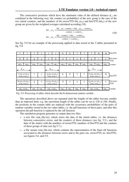
LTE Emulator version 1.0 – technical report The consecutive positions which have the minimum value of the defined distance dt_i are combined in the following way: the counter (or probability) of the new group is the sum of the two initial counters, and the numbers of bit errors/TTI (bit_erni) and bits/TTI (bitni) of the new group are given by the weighted averages calculated according (10). bit _ er ni bit _ er ni bit _ eri ⋅ contori + bit _ er = contor + contor i−1 i−1 i−1 biti ⋅ contori + biti −1 ⋅ contor = contor + contor i i ⋅ contor See fig. 5.9 for an example of the processing applied to data stored in the 3 tables presented in fig. 5.8. i i i j j j k k l l l m m b d g a e h d e a e g c e cnti-b cnti-d cnti-g cntj-a cntj-e cntj-h cntk-d cntk-e cntl-a cntl-e cntl-g cntm-c cntm-e dt_m dt_m dt_m (i⋅cnti-b+i⋅cnti-d) /(cnt i-b+cnt i-d) (b⋅cnt i-b+d⋅cnt i-d) /(cnti-b+cnti-d) i j (j⋅cntj-e+j⋅cntj-h) /(cnt j-e+cnt j-h) g a (e⋅cnt j-e+h⋅cnt j-h) /(cntj-e+cntj-h) no. errors/TTI - no. bits/TTI related to the decrease of these table lengths. The operations described above are repeated until the lengths of the tables become smaller than an imposed limit; e.g. the maximum length of the tables can be set to 128 or 256. Finally, the positions in the counter table are replaced with the occurrence probabilities of the pairs of random variables stored in the two other tables, i.e. the pdf functions of these pairs, and after this operation the pdf function is replaced by the cdf function. The simulation program generates as output data two files: o a text file (stat_file.txt), which stores the data of the initial tables, i.e. the distances between consecutive errors, and the counters of these distances (see fig. 5.5.), and the data of the matrix with the numbers of errors/TTI, numbers of bits/TTI and the counters of these groups of data (see fig 5.7.); o a file stream (stat_file.sta), which contains the representation of the final cdf functions associated to the distances between errors and to the pairs (no. errors/TTI; no. bits/TTI), see figures 5.6. and 5.9. i−1 i−1 k k l l (l⋅cntl-g+m⋅cntm-c) /(cnt l-g+cnt m-g) d e a e (g⋅cnt l-g+c⋅cnt m-c) /(cntl-g+cntm-g) cnti-b+cnti-d cnti-g cntj-a cntj-e+cntj-h cntk-d cntk-e cntl-a cntl-e cntl-g+cntm-c cntm-e Fig. 5.9. Processing of tables which describe the bi-dimensional random variable. m e (10) bits/TTI bit errors /TTI counter bits/TTI bit errors /TTI counter 29
TUCN – Data Transmission Laboratory 6. Compatibility with 3GPP standards. Possible developments 6.1. Compatibility with E-UTRA standards To evaluate the compatibility of the present version 1 (drop 1) of the emulator and simulator with the 3GPP E-UTRA standards the following aspects are considered: 30 1. the physical layer for the downlink transmission – frame structure, transmission scheme, link adaptation; 2. data transfer at layer 2 (MAC and RRC) – frame structures, buffer management, ARQ and HARQ operations, mapping of the logical channels on the transport channels; 3. QoS concepts, service bearer architecture and scheduling/rate control operations (Dynamic Resource Allocation – DRA or Packet Scheduling - PS); The compatibility analysis regarding the uplink connection (physical layer and layer 2), management and transmission on signaling channels and mobility management can be performed only after the implementation or at least the design of the blocks in discussion in the emulator and in the simulator. Paragraph 6.2. presents several considerations regarding the insertion of the blocks mentioned above in the implemented emulator-simulator and the processing required. 1. Compatibility at the physical layer - downlink. The [3GPP07] standard proposes for the downlink physical layer (chapter 5 [3GPP07]) the following features: o a 10ms radio frame composed of 20 slots with 0.5ms duration (an alternative variant for the TDD duplex mode contains 12 slots). 12 consecutive OFDM sub-carriers during one slot period compose a resource block. This resource block corresponds practically to a chunk (or bin) and has duration of one TTI interval. Several resource blocks can be allocated to a service (user). The employment of pilot sub-carriers inside the resource block is not specified (at least until the elaboration of the present material). The OFDM sub-carrier separation can be 15 kHz or 7.5 kHz and the used cyclic prefix varies from on resource block to other (see [3GPP07 chapter 5]). Some of the first and last OFDM symbols of the radio frame are used to transmit some information regarding the resource allocation, ARQ/HARQ processes, ACK/NACK signaling, uplink scheduling and reference signals for cell identification; o turbo codes are proposed as coding techniques, one code being used for the data of all resource blocks associated to a layer 2-connection. The QPSK, 16QAM or 64QAM modulations are considered, the same modulation being used in all resource blocks associated to a layer 2-connection. The modulation technique and the parameters of the coding techniques can be modified adaptively from one slot to another. Static or semi-static (combination of static and adaptive) use of modulation and coding techniques is also allowed; o the standard also includes the possibility to use multi-antenna techniques with 2 or 4 transmit antennas and the use of power control; The simulator associated to the implemented emulator has the following features: o it allows the use of chunks with variable dimensions, the modification of OFDM modulation parameters, but the cyclic prefix is the same for all the OFDM symbols. It does not offer the possibility to use some groups of OFDM symbols for the transmission of signaling information; o it uses a single LDPC code on a group of chunks associated to a layer 2-connection and the allowed modulation techniques are 2PSK, QPSK, 16QAM and 64 QAM and optionally 256QAM. The modulation techniques can vary adaptively from one chunk to other, thus providing a higher flexibility in modifying the instantaneous bit rate;
- Page 1 and 2: LTE Emulator (downlink connection)
- Page 3 and 4: TUCN - Data Transmission Laboratory
- Page 5 and 6: TUCN - Data Transmission Laboratory
- Page 7 and 8: TUCN - Data Transmission Laboratory
- Page 9 and 10: TUCN - Data Transmission Laboratory
- Page 11 and 12: TUCN - Data Transmission Laboratory
- Page 13 and 14: TUCN - Data Transmission Laboratory
- Page 15 and 16: TUCN - Data Transmission Laboratory
- Page 17 and 18: TUCN - Data Transmission Laboratory
- Page 19 and 20: TUCN - Data Transmission Laboratory
- Page 21 and 22: TUCN - Data Transmission Laboratory
- Page 23 and 24: TUCN - Data Transmission Laboratory
- Page 25 and 26: TUCN - Data Transmission Laboratory
- Page 27 and 28: TUCN - Data Transmission Laboratory
- Page 29: TUCN - Data Transmission Laboratory
- Page 33 and 34: TUCN - Data Transmission Laboratory
- Page 35 and 36: TUCN - Data Transmission Laboratory
- Page 37 and 38: TUCN - Data Transmission Laboratory
- Page 39 and 40: TUCN - Data Transmission Laboratory
<strong>LTE</strong> <strong>Emulator</strong> version 1.0 – technical report<br />
The consecutive positions which have the minimum value of the defined distance dt_i are<br />
combined in the following way: the counter (or probability) of the new group is the sum of the<br />
two initial counters, and the numbers of bit errors/TTI (bit_erni) and bits/TTI (bitni) of the new<br />
group are given by the weighted averages calculated according (10).<br />
bit _ er<br />
ni<br />
bit _ er<br />
ni<br />
bit _ eri<br />
⋅ contori<br />
+ bit _ er<br />
=<br />
contor + contor<br />
i−1<br />
i−1<br />
i−1<br />
biti<br />
⋅ contori<br />
+ biti<br />
−1<br />
⋅ contor<br />
=<br />
contor + contor<br />
i<br />
i<br />
⋅ contor<br />
See fig. 5.9 for an example of the processing applied to data stored in the 3 tables presented in<br />
fig. 5.8.<br />
i i i j j j k k l l l m m<br />
b d g a e h d e a e g c e<br />
cnti-b cnti-d cnti-g cntj-a cntj-e cntj-h cntk-d cntk-e cntl-a cntl-e cntl-g cntm-c cntm-e<br />
dt_m dt_m dt_m<br />
(i⋅cnti-b+i⋅cnti-d)<br />
/(cnt i-b+cnt i-d)<br />
(b⋅cnt i-b+d⋅cnt i-d)<br />
/(cnti-b+cnti-d)<br />
i j (j⋅cntj-e+j⋅cntj-h)<br />
/(cnt j-e+cnt j-h)<br />
g a (e⋅cnt j-e+h⋅cnt j-h)<br />
/(cntj-e+cntj-h)<br />
no. errors/TTI - no. bits/TTI related to the decrease of these table lengths.<br />
The operations described above are repeated until the lengths of the tables become smaller<br />
than an imposed limit; e.g. the maximum length of the tables can be set to 128 or 256. Finally,<br />
the positions in the counter table are replaced with the occurrence probabilities of the pairs of<br />
random variables stored in the two other tables, i.e. the pdf functions of these pairs, and after this<br />
operation the pdf function is replaced by the cdf function.<br />
The simulation program generates as output data two files:<br />
o a text file (stat_file.txt), which stores the data of the initial tables, i.e. the distances<br />
between consecutive errors, and the counters of these distances (see fig. 5.5.), and the<br />
data of the matrix with the numbers of errors/TTI, numbers of bits/TTI and the counters<br />
of these groups of data (see fig 5.7.);<br />
o a file stream (stat_file.sta), which contains the representation of the final cdf functions<br />
associated to the distances between errors and to the pairs (no. errors/TTI; no. bits/TTI),<br />
see figures 5.6. and 5.9.<br />
i−1<br />
i−1<br />
k k l l (l⋅cntl-g+m⋅cntm-c)<br />
/(cnt l-g+cnt m-g)<br />
d e a e (g⋅cnt l-g+c⋅cnt m-c)<br />
/(cntl-g+cntm-g)<br />
cnti-b+cnti-d cnti-g cntj-a cntj-e+cntj-h cntk-d cntk-e cntl-a cntl-e cntl-g+cntm-c cntm-e<br />
Fig. 5.9. Processing of tables which describe the bi-dimensional random variable.<br />
m<br />
e<br />
(10)<br />
bits/TTI<br />
bit errors<br />
/TTI<br />
counter<br />
bits/TTI<br />
bit errors<br />
/TTI<br />
counter<br />
29


