Technical Specification for a typical 40'x 8' - Steinecker ...
Technical Specification for a typical 40'x 8' - Steinecker ...
Technical Specification for a typical 40'x 8' - Steinecker ...

Create successful ePaper yourself
Turn your PDF publications into a flip-book with our unique Google optimized e-Paper software.
Stand Dez. 2012<br />
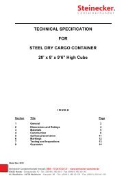
<strong>Technical</strong> <strong>Specification</strong><br />
<strong>for</strong> a <strong>typical</strong><br />
<strong>40'x</strong> <strong>8'</strong>x <strong>8'</strong>6" ISO Type<br />
Steel Dry Cargo Container<br />
“DOUBLE DOOR”<br />
Double wing doors at both ends<br />
<strong>Steinecker</strong> Containerhandel freecall: 0800 - 78 34 63 25 37 - www.steinecker-container.de<br />
63452 Hanau · Donaustraße 10 · Tel.: (06181) 180 40 0 · Fax (06181) 180 40 110<br />
NL Waldheim: 04736 Waldheim · Hauptstr. 86 · Tel.: (06181) 180 40 131 · Fax: (06181) 180 40 130
CONTENTS<br />
1 . GENERAL ....................................................................................... 3<br />
2 . APPROVAL AND CERTIFICATES ................................................. 3<br />
3 . HANDLING ...................................................................................... 4<br />
4 . TRANSPORTATION ......................................................................... 4<br />
5 . DIMENSIONS AND RATINGS ........................................................ 5<br />
6 . CONSTRUCTION ............................................................................. 6<br />
7 . PRESERVATION .............................................................................. 12<br />
8 . MARKINGS ....................................................................................... 13<br />
9 . TESTING AND INSPECTION ......................................................... 14<br />
10. DOCUMENTS SUBMISSION ......................................................... 15<br />
11. MATERIALS ..................................................................................... 16<br />
2
1. General<br />
1.1 Operational Environment<br />
The container will be designed and constructed <strong>for</strong> the transportation of general<br />
cargo on sea ( above or under deck ) and on land ( road or rail ) throughout the<br />
world, and will be suitable <strong>for</strong> the environmental conditions imposed by those<br />
modes of transport. All materials used in the construction will be able to<br />
withstand extreme temperature ranging from -40°C(-40°F) to 70°C(158°F)<br />
without effect on container's strength and watertightness.<br />
1.2 Standards , Regulations and Rules<br />
1.2.1 Standards and Regulations<br />
Containers shall comply with following in their latest editions:<br />
1) I.S.O./TC-104<br />
668 - Series 1 freight containers-Classification, external dimensions and<br />
ratings<br />
6346 - Coding, identification and marking <strong>for</strong> freight containers<br />
1161 - <strong>Specification</strong> of corner fittings <strong>for</strong> series 1 freight containers<br />
1496/1 - <strong>Specification</strong> and testing of series 1 freight containers.<br />
Part 1 : General cargo containers <strong>for</strong> general purposes<br />
830 - Freight containers-Terminology.<br />
2) The International Union of Railway (UIC) code 592 OR.<br />
3) The Customs Convention on the International Transport of Goods(T.I.R.).<br />
4) The International Convention <strong>for</strong> Safe Containers (CSC).<br />
5) Transportation Cargo Containers and Unit Loads Quarantine Aspects and<br />
Procedures by Commonwealth of Australia Department of Health. (T.C.T.)<br />
1.2.2 To satisfy the requirements of Rules of B.V, LR, GL, CCS or A.B.S..<br />
2. Approval and Certificates<br />
2.1 Classification Certificate<br />
All the containers shall be certified <strong>for</strong> design type and individually inspected by<br />
Classification Society.<br />
2.2 Production Certificate<br />
The Production Certificate of series containers to be issued by the<br />
Classification Society. The Society's seal shall be provided.<br />
2.3 T.C.T Certificate<br />
Certificate of timber treatment to the requirement of Australia Department of<br />
Health.<br />
3
2.4 Customs Certificate (T.I.R.)<br />
Customs' Approval and Certificate to be issued by Customs.<br />
2.5 U.I.C. Registration<br />
All the containers will be registered & comply with the International Union of<br />
Railways.<br />
2.6 C.S.C. Certificate<br />
All the containers will be certified and comply with the requirements of the<br />
International Convention <strong>for</strong> Safe Containers.<br />
3. Handling<br />
The container will be constructed to be capable of being handled without any<br />
permanent de<strong>for</strong>mation which will render it unsuitable <strong>for</strong> use or any other<br />
abnormality during the following conditions:<br />
1) Lifting, full or empty, at the top corner fittings vertically by means of<br />
spreaders fitted with hooks, shackles or twistlocks.<br />
2) Lifting, full or empty, at the bottom corner fittings using slings with<br />
appropriate terminal fittings at slings angle of thirty (30°) degrees to<br />
horizontal.<br />
4. Transportation<br />
The container shall be constructed to be suitable <strong>for</strong> transportation <strong>for</strong> following<br />
modes without any permanent de<strong>for</strong>mation which will render the container<br />
unsuitable to use or any other abnormality.<br />
4.1 Marine:<br />
- In the ship cell guides: Eight ( 7 ) high stacked( Max. gross weight 30,480<br />
kg )<br />
- On the deck : Four ( 4 ) high stacked and secured by suitable vertical and<br />
diagonal wire lashings.<br />
4.2 Road - On flat bed or skeletal chassis:<br />
Secured by twistlocks or the equivalent at the four bottom corner fittings.<br />
4.3 Rail - On the flat cars or special container car:<br />
Secured by twistlocks or the equivalent at the four bottom corner fittings.<br />
4
5 . Dimensions and Ratings<br />
5.1 Dimension<br />
External Dimensions Internal Dimensions<br />
Length 12,192 ( 0, -10 ) mm 12,032 ( 0, -10 ) mm<br />
Width 2,438 ( 0, -5 ) mm 2,352 ( 0, -5 ) mm<br />
Height 2,591 ( 0, -5 ) mm 2,393 ( 0, -5 ) mm<br />
No part of the container will protrude out beyond the external dimensions<br />
mentioned above.<br />
Maximum allowable difference between two diagonals on any one of the<br />
following surface are as follow:<br />
Roof, Bottom and Side Diagonals .......... 19mm<br />
Front and Rear Diagonals .......... 10 mm.<br />
5.2 Door Opening<br />
Width .................. 2,340 ( 0,-5 ) mm<br />
Height ................... 2,280 ( 0,-5 ) mm<br />
5.3 Gooseneck Tunnel<br />
Length .................. 3,266 mm<br />
Width .................. 1,029 ( +3,0 ) mm<br />
Height ................... 120 ( 0,-3 ) mm<br />
5.4 Inside Cubic Capacity<br />
67.3 cu.m 2,376 cu.ft<br />
5.5 Rating<br />
Maximum Gross Weight .............. 30,480 kg 67,200 lbs<br />
Maximum Payload ......….…. 26480 kg 58380 lbs<br />
Tare Weight (±2%) ..........…… 4000 kg 8820 lbs<br />
5.6 Corner Protrusions<br />
1) The upper faces of the top corner fittings will protrude above the highest<br />
level of the roof construction except corner plate by 6 mm.<br />
2) For the containers under empty condition the lower faces of the cross<br />
members in their bases including their end transverse members shall be on<br />
a plane located at least 17 mm above the lower faces of the bottom corner<br />
fittings.<br />
3) The outer side faces of the corner fittings will protrude from the outside<br />
faces of the corner post by minimum 3 mm. The outer side faces of the<br />
corner fittings will protrude from the outside faces of the side walls by<br />
nominal 7 mm and from the outside faces of the front end wall by 7.4 mm.<br />
4) For the containers under the condition such as the load equal to 1.8R - T<br />
5
uni<strong>for</strong>mly distributed over the floor, no part of the container base will deflect<br />
more than 6 mm below the lower faces of the bottom corner fittings.<br />
6. Construction<br />
6.1 General<br />
The container will be constructed with steel frames, fully vertically corrugated<br />
steel side and end walls, die-stamped corrugated steel roof, wooden flooring,<br />
corrugated double hinged doors and ISO corner fittings at eight corners. All<br />
steelworks will be built up by means of automatic and semi-automatic CO2 gas<br />
arc welding.<br />
6.1.1 Welding<br />
1) The welding between the corner posts and the rails shall be continuous<br />
single welding.<br />
2) The external welding between the corner posts and the front/side panels<br />
shall be continuous welding and the internal welding shall be as follows:<br />
A. The continuous welding shall be 100 mm from the top and bottom.<br />
B. The intermediate “ tack welding “ shall be 25 mm in every 200 mm and<br />
sealant shall be applied between the welding beads.<br />
3) Weld penetration at connection points between side/front panels and frame<br />
of the container shall not be less than 75% at any point.<br />
4) The crossmembers shall be continuous welded to the bottom side rails on<br />
both side.<br />
5) All the welds, even spots, will have full penetration without undercutting or<br />
porosity.<br />
6.2 Corner Fittings<br />
Corner fittings will be designed in accordance with ISO/1161 standard, and<br />
manufactured at the workshops approved by the classification society.<br />
6.3 Base Frame<br />
The base frame will be composed of two (2) bottom side rails, a number of<br />
crossmembers and a gooseneck tunnel, which are welded together as a<br />
sub-assembly.<br />
6.3.1 Bottom Side Rail<br />
Each bottom side rail is built of a steel pressing made in one piece. The bottom<br />
flange face outwards so as to be easily repaired and hard to corrode.<br />
Qty. : Two ( 2 ).<br />
Shape : Channel Section .<br />
Dimension : 162 x 48 x 30 x 4.5 mm.<br />
6
6.3.2 Crossmember<br />
The crossmembers are composed of a number of small pressed channel<br />
section and some large one with three 4.0 mm thick webs located beneath<br />
each board joint of the plywood, which are placed at certain center distance.<br />
Shape : " C " section<br />
Small one : 122 x 45 x 40 x 4.0 mm , Qty. : 25<br />
Large one : 122 x 75 x 40 x 4.0 mm , Qty. : 3<br />
6.3.3 Gooseneck Tunnel<br />
The gooseneck tunnel consists of one piece pressed hat section tunnel plate, a<br />
number of pressed channel section tunnel bows, one welded box section rear<br />
bolster and tunnel outriggers. The gooseneck tunnel is designed according to<br />
ISO standard:<br />
a) Tunnel plate thickness : 4.0 mm Qty. : 1<br />
b) Tunnel bow thickness : 4.0 mm Qty. : 12<br />
c) Bolster thickness: 150x100x4.0 mm, Qty. : 1<br />
d) Outriggers - "C" section: 118x75x40x4.0 mm, Qty. : 1/each side<br />
118x45x40x4.0 mm, Qty. : 7/each side<br />
6.3.4 Rein<strong>for</strong>cement<br />
Rein<strong>for</strong>cement plates will be welded at two ends of bottom side rail.<br />
Dimension: 200 x 150 x 4.0 mm<br />
6.4 REAR & FRONT DOOR<br />
Rear end is composed of Rear End Frame which consists of one door sill, two<br />
corner posts, one rear header with header plate and four corner fittings, which<br />
are welded together as a sub-assembly, and Door Systems with locking<br />
devices.<br />
6.4.1 Door Sill<br />
The door sill is built of a special channel section steel pressing with internal ribs<br />
as stiffeners at the back of each cam keeper. The upper face of the sill has a<br />
slope <strong>for</strong> better drainage and the highest part is on the same level to the upper<br />
face of the wooden floor.<br />
a) Door sill(rear) : 4.5 mm thick Slope : 1:10 approx.<br />
b) Stiffener ribs : 4.5 mm thick Qty. : 4 Pcs.<br />
c) Door sill(front) 4.0 mm thick 1 Pcs<br />
d) Door sill(front) 10 mm thick 1 Pcs<br />
7
6.4.2 Corner Post<br />
Each corner post is constructed from an inner part of channel shaped hot-rolled<br />
section steel and an outer part of steel pressing, welded together to <strong>for</strong>m a<br />
hollow section to ensure the door opening and suitable strength against the<br />
stacking and racking <strong>for</strong>ce. Four ( 4 ) sets of hinge pin lugs are welded to each<br />
outer part of the corner post.<br />
Inner part : 113 x 40 x 12 mm<br />
Outer part : 6.0 mm thick<br />
6.4.3 Door Header<br />
The door header is constructed from a lower part of a " U " shaped steel<br />
pressing with internal stiffener ribs at the location of the back of cam keeper<br />
and an upper part of steel pressing rear header plate, they are welded together<br />
to <strong>for</strong>m a box section to provide a high rigidity.<br />
Rear header : 4.0 mm thick<br />
Header plate : 3.0 mm thick<br />
Rib : 4.0 mm thick , Qty. : 4<br />
6.4.4 Door Systems<br />
Doors will consist of two door leaves, each leaf with two locking devices, four<br />
hinges and pins, seal gaskets and the door holders. The doors will be installed<br />
by hinge pins to the rear end frame and capable of swinging about 270<br />
degrees.<br />
6.4.4.1 Door Leaves<br />
Each leaf consists of door panel, steel door frame which consists of horizontal<br />
( upper & lower ) and vertical ( inner & outer ) members. They are welded<br />
together to <strong>for</strong>m the rectangular door leaf. The door are so arranged that the<br />
left leaf can not be opened without displacement of the right leaf.<br />
1) Door panel : With 3 corrugations<br />
Depth : 36 mm<br />
Inner face : 72 mm<br />
Slope : 68 mm<br />
Panel thickness : 2.0 mm<br />
2) Door frame :<br />
a) Vertical door member: 100x50x3.2 mm RHS (inner & outer)<br />
b) Horizontal door member: 150x50x3.0 mm, channel section<br />
8
6.4.4.2 Hinges and Pins<br />
Four <strong>for</strong>ged hinges, providing with bushed hole, are welded to each door leaf.<br />
Each door is installed by hinge pins, washers and bushings.<br />
Washer - Material : Stainless steel<br />
Location : Under the bottom of hinge<br />
Bushing - Self-lubricating synthetic<br />
Pin - Material : Stainless steel<br />
6.4.4.3 Locking Devices<br />
Two locking bars are of steel tube with handles, anti-racking rings and cam<br />
ends, and fixed to each door leaf with bolts / nuts and six huck bolts at TIR<br />
locations, by top and bottom bearing brackets and one bar guide bracket. The<br />
bars are suspended in bearing brackets with bush of self-lubricating synthetic<br />
material. The locking device to be installed after painting.<br />
The EPDM shim will be placed over the holes on the door <strong>for</strong> fastener.<br />
Cam-keepers are welded to the door header and sill.<br />
a) Locking device type: SEA JIN OR BE 2566MN<br />
b)Locking bars treatment: Hot-Dipped galvanized (75 Microns)<br />
6.4.4.4 Door Holder and Receptacle<br />
A door holder per door, made of mixed nylon rope, is tied to the center side<br />
locking rod & the receptacle ( door hook ) is welded to each bottom side rail to<br />
remain the door at the open position.<br />
6.4.4.5 Seal Gaskets<br />
The door seal gaskets ( black colour ) are of E.P.D.M rubber assembled by<br />
rivets, using strip retainers and adhesive sealant on the back.<br />
Gasket's shape : "J - C" Type<br />
Retainer : Stainless steel<br />
Rivet : Stainless steel<br />
6.5 Side Wall Assembly<br />
6.5.1 Top Side Rails<br />
Each top side rail is used a square steel pipe.<br />
Rail : 60 x 60 x 3.0 mm RHS<br />
6.5.2 Side Walls<br />
Each side wall will be composed of a number of sheets <strong>for</strong> the intermediate<br />
(inner) parts and outer panels at each end of side wall, fully vertically<br />
corrugated into trapezium section, butt welded together to <strong>for</strong>m one panel by<br />
automatic welding.<br />
a) Inner panel : 1.6 mm Thk. , Qty. : 9 Pcs/Each side<br />
b) Outer panel : 2.0 mm Thk. , Qty. : 2 Pcs/Each side<br />
9
c) Trapezium :<br />
Outer face : 72 mm , Slope : 68 mm<br />
Inner face : 70 mm , Depth : 36 mm<br />
Pitch : 278 mm ,<br />
6.6 Roof<br />
The roof will be constructed by several die-stamp corrugated steel sheets with<br />
a certain upwards camber at the center of each trough and corrugation, these<br />
sheets are butt jointed together to <strong>for</strong>m one panel by automatic welding.<br />
Corrugation Shape - Depth : 20 mm , Pitch : 209 mm<br />
Inter face : 91 mm , Slope : 13.5 mm<br />
Outer face : 91 mm ,<br />
Camber upwards : 5 mm<br />
Panel thickness : 2.0 mm<br />
Sheet Qty. : 11 Pcs.<br />
6.6.1 Roof rein<strong>for</strong>cement plate<br />
Four 3.0 m thick rein<strong>for</strong>cement plates shall be mounted around the four corner<br />
fittings.<br />
6.7 Floor<br />
6.7.1 The Floor Boards<br />
The floor consists of plywood. The plywood is treated with preservative<br />
according to the latest requirement of Commonwealth Department of Health,<br />
Australia.<br />
Plywood thickness : 28 mm<br />
Plywood moisture content : Less than 14 %<br />
Plywood ply number : MIn19 plies<br />
Plywood material : Apitong/Hardwood<br />
6.7.2 Arrangement and Fixing<br />
The plywood boards are longitudinally laid on the crossmember with a<br />
pre-blasted painted and free floating flat steel at the center, two angle steel<br />
along both side rails. The plywood boards are tightly secured to each<br />
crossmember with countersunk self-tapping electro-zinc plated steel screws.<br />
These heads of the floor screws are countersunk below the level of the upper<br />
surface of the floor by 1.5 mm to 2.5 mm.<br />
Screws : M8 x 45 x Φ16(head) , Electro zinc plated<br />
Screws’ Qty. : 6 Pcs/end row, 4 Pcs/other, 3 Pcs/outrigger<br />
Floor centre rail : 50 x 4 mm, Primed and painted<br />
"L" section : 3.0 mm Thk.<br />
10
6.8 Special Features<br />
6.8.1 Customs Seal Provision<br />
Customs seal provision are made on each locking handle and retainer in<br />
accordance with TIR requirements.<br />
6.8.2 Lashing rings<br />
1) Lashing rings are welded to each bottom and top side rail at corresponding<br />
recessed area of side wall.<br />
Lashing ring Qty./ Each bottom or top side rail: 10, Total : 40<br />
2) Lashing rods are welded on each rear & front corner post slot.<br />
Lashing rods Qty. / Each front corner post: 3, Total: 6<br />
Lashing rods Qty. / Each rear corner post: 3, Total: 6<br />
3) Capabilities of pull load of every lashing point are as following:<br />
a) Lashing rings on the side rails : 1,500 kg/each<br />
b) Lashing rods on the corner posts : 1,000 kg/each<br />
4) Treatment of lashing ring / bar : Electro zinc plated<br />
6.8.3 Sill Cut-Outs<br />
200 x 75 x 9 mm channel section steel recesses are provided in each end of<br />
rear and front sill adjacent to the bottom fitting to prevent damage due to any<br />
twistlocks misalignment.<br />
6.8.4 Ventilators<br />
One ventilator is supplied on each side wall at the right-hand end when facing<br />
the side from outside of container, fixed by three aluminum huck bolts, the<br />
silicone sealant is to be applied on the edges except the bottom side of the<br />
ventilator, after the completion of paint.<br />
Quantity : 1 / each side panel<br />
Material : ABS Labyrinth Type.<br />
7. Preservation<br />
7.1 Surface Preparation of the Steelwork<br />
1) All the steel surface prior to <strong>for</strong>ming or after will be degreased and shot<br />
blasted to Swedish Standard SA 2.5 to obtain the surface roughness at 25 to<br />
35 microns which can result in the removement of all the rust, dirt, mill scale<br />
and all other <strong>for</strong>eign materials.<br />
2) Locking rod assemblies, which are welded with gear cams, bars holder and<br />
handle hinges, are hot dipping galvanized (Thickness : 75 microns).<br />
3) All fasteners such as bolts/nuts, washers, self-tapping screws, which are not<br />
mentioned in this Spec. will be electro zinc plated to 13 Microns.<br />
11
4) Hinges and cam-keepers will be electro zinc plated to 13 Microns.<br />
5) Sealant <strong>for</strong> joints<br />
Each perimeter of the floor, all the overlapped joints of inside, all the holes<br />
<strong>for</strong> bolts and nuts and all the places where may leak water will be sealed to<br />
give prevention against water entry.<br />
Sealant Materials:<br />
a. Chloroprene ( Cargo contact area )<br />
b. Butyl ( Hidden parts )<br />
7.2 Coating<br />
7.2.1 Prior to Assembly<br />
All the steel surface will be coated with primer paint immediately after<br />
shot-blasting .<br />
7.2.2 After Assembly<br />
All the weld joints will be shot-blasted to remove all the welding fluxes, spatters,<br />
burnt primer coatings caused by welding heat, and other <strong>for</strong>eign materials, and<br />
followed with the secondary paint operation immediately.<br />
7.2.3 All the surface of the assembled container will have coating system as follows :<br />
Process Paint Name DFT ( µ )<br />
Exterior Surface Epoxy zinc rich primer 30<br />
Epoxy primer 40<br />
Acrylic top coat 50<br />
Total: 120<br />
Interior Surface Epoxy zinc rich primer 30<br />
Epoxy topcoat, Colour: RAL 7035 40<br />
Total: 70<br />
Under Structure Epoxy zinc rich primer 30<br />
Waxy Bitumen 200<br />
Total: 230<br />
* Epoxy zinc rich primer and epoxy topcoat are not applied to the wooden floor.<br />
12
8. Markings<br />
8.1 Lettering<br />
The markings will be designed decal and arranged according to buyer's<br />
requirement. The markings consist of the following contents:<br />
1) Owner's emblems .......... according to owner's design.<br />
2) Owner's code , serial number and check digit ( outside & inside )<br />
3) Size and type code ( outside )<br />
4) Weight details ( on door )<br />
5) Other marking: According to owner's requirements.<br />
6) Material of marking: According to owner's requirements.<br />
8.2 Consolidate Plate<br />
8.2.1 The containers will bear marking plate in accordance with the requirements of<br />
the Classification Authorities and owner such as mentioned in section 2.2 in<br />
this specification. The plate will be permanently riveted to the specified position<br />
by rivets.<br />
Plate material : STAINLESS STEEL<br />
Plate treatment : Chemically etched & enameled<br />
Rivets material : Stainless steel<br />
Plate thickness : 0.8 mm<br />
8.2.2 Contents of the Plate<br />
1) Owner's plate ( name and address ) .<br />
2) CSC approval No.<br />
3) Customs approval No.<br />
4) Australian wood treatment .<br />
The engraved letters on this plate are as following :<br />
IM : Immunization<br />
XXXX: The name of preservative.<br />
XXXX: The time of immunization.<br />
5) Date of manufacture (year-engraved, month-stamped)<br />
6) Owner's serial number (stamped)<br />
7) Owner's model number.<br />
9. Testing and Inspection<br />
9.1 Proto-type Container<br />
Proto-type container to be manufactured in accordance with this specification<br />
and shall be tested according to procedures described in the ISO 1496/1 and<br />
the Classification Society's requirements. The containers will be fabricated &<br />
tested in advance of the mass production.<br />
13
9.2 Container in Mass Production<br />
9.2.1 Every container in mass production shall be manufactured under<br />
effective quality control procedures to meet the specified standards. One in<br />
every 100 of containers shall be tested <strong>for</strong> following items:<br />
a) Stacking test<br />
b) Lifting from top corner fitting test<br />
c) Lifting from bottom corner fitting test<br />
d) Floor test.<br />
After completion, all the containers shall be subject to dimension check, door<br />
operation check, light leakage test & production type weather-proofness test.<br />
The containers shall be inspected by the surveyor of Classification Society and<br />
identified by the appropriate society seal.<br />
9.2.2 Each assembled corner post structure will have tension test with<br />
15,240 kgs after welding in the construction line.<br />
9.3 The proposed criteria table <strong>for</strong> general prototype testing:<br />
Test No. Test Load Method<br />
a. Stacking Internal Load:<br />
1.8R-T<br />
Testing load:<br />
b. Lifting from Top<br />
Corner Fittings<br />
c. Lifting from<br />
Bottom Corner<br />
Fittings<br />
d. Restraint<br />
(Longitudinal)<br />
86,400kg/post<br />
Internal Load:<br />
2R-T<br />
Internal Load:<br />
2R-T<br />
Testing load:<br />
2R(R/side)<br />
Internal Load:<br />
R-T<br />
e. Floor Strength Truck Load:<br />
7,260 kg<br />
f. Wall Strength Test Load:<br />
(Front & Door) 0.4 P<br />
g. Side Wall Strength Test Load:<br />
0.6 P<br />
h. Roof Strength Test Load:<br />
300 kg<br />
Hydraulic cylinder load to corner post through<br />
top corner fittings.<br />
Time duration : 5 mins .<br />
Lifting vertically from top corner fittings.<br />
Time duration : 5 mins .<br />
Lifting from bottom corner fitting 30 Deg. to<br />
horizontal.<br />
Time duration : 5 mins .<br />
Hydraulic cylinder load applied to bottom side<br />
rails in compression & then tension .<br />
Time duration : 5 mins .<br />
Special truck is used.<br />
Total contact area: 284 sq cm,<br />
Wheel width: 180 mm,<br />
Wheel center distance: 760 mm<br />
Compressed air bag is used.<br />
Time duration : 5 mins.<br />
Compressed air bag is used.<br />
Time duration : 5 mins.<br />
Applied area will be the weakest place of 600<br />
x 300 mm longitudinal & transverse.<br />
14
i. Rigidity<br />
(Transverse)<br />
j. Rigidity<br />
(Longitudinal)<br />
k. One door off<br />
operation<br />
Test Force:<br />
15,240 kg<br />
(150 kn)<br />
Test Force:<br />
7,620 kg<br />
(75 kn)<br />
Test load:<br />
Stacking:27,450<br />
kg/post<br />
Racking:7,500k<br />
g<br />
Time duration : 5 mins .<br />
Hydraulic cylinder will be applied to front top<br />
end rail & door header through top corner<br />
fittings, each time pulling & pushing.<br />
Time duration : 5 mins .<br />
Hydraulic cylinder load will applied to side top<br />
rail through top corner fittings.<br />
Time duration : 5 mins .<br />
Hydraulic cylinder should be first to top of<br />
corner post, racking load should be applied,<br />
then additionally stacking load should be<br />
applied simultaneously.<br />
l. Weather Nozzle: 12.5 mm (inside dia.) Distance: 1.5 m<br />
proofness Pressure: 100 kpa (1 kg/sq.cm) Speed: 100 mm/Sec.<br />
* Note: R - Maximum gross weight<br />
T - Tare weight<br />
P - Maximum payload<br />
9.4 Inspection<br />
9.4.1 Materials and Component Parts Inspection<br />
All the materials and components will be inspected by Quality Control Dept. to<br />
make sure that the most suitable and qualified components being used <strong>for</strong> the<br />
containers and to meet this specification.<br />
9.4.2 Production Line Inspection<br />
Every containers will be manufactured under effective Quality Control<br />
procedures, and every production line of the factory will be inspected and<br />
controlled by the Quality Control Dept. to meet this specification.<br />
10. Documents Submission<br />
10.1 When Contracting<br />
Manufacturer shall submit the specification with following drawing ( 3 sets ):<br />
General arrangement Side wall assembly<br />
Base assembly Front end assembly<br />
Rear end assembly Marking arrangement<br />
10.2 When delivery<br />
The owner shall in<strong>for</strong>m Manufacturer all the documents needed two weeks<br />
be<strong>for</strong>e the date of delivery and Manufacturer will submit them to the owner .<br />
15
11. Materials<br />
The main materials used in construction are as follows or approved equivalent:<br />
Where used Materials<br />
Front End Assembly<br />
Front corner post Corten A<br />
Front sill Corten A<br />
Front panel Corten A<br />
Front header cap Corten A<br />
Front rail Corten A<br />
Base Assembly<br />
Bottom side rail Corten A<br />
Crossmember Corten A<br />
Gooseneck tunnel Corten A<br />
Outrigger Corten A<br />
Floor centre rail Corten A<br />
Floor support angle Corten A<br />
Rear End Assembly<br />
Rear corner post ( outer ) Corten A<br />
Rear corner post ( inner ) SM50YA (or SS50)<br />
Door sill Corten A<br />
Rear header cap Corten A<br />
Door header lower Corten A<br />
Door panel frame Corten A<br />
Door panel Corten A<br />
Door hinge S25C, Elector Zinc Plated<br />
Door hinge pin Stainless steel<br />
Locking device HaiHang OR SJ13-BF<br />
Locking cam, cam keeper S20C<br />
Locking rod STKR41<br />
Door gasket E.P.D.M<br />
Gasket retainer Stainless steel<br />
Washer Stainless steel<br />
Rivet Stainless steel<br />
Shim E.P.D.M.<br />
Corner fitting SCW49<br />
Side Wall Assembly<br />
Side panel Corten A<br />
Top side rail Corten A<br />
Lashing bar, lashing ring SS41, Electro zinc plated<br />
Ventilator A.B.S<br />
16
Stand April 2010<br />
Roof<br />
Roof corner gusset Corten A<br />
Roof panel Corten A<br />
Floor<br />
Floor board Plywood (Apitong/Hardwood )<br />
Floor screw Electro zinc plated<br />
Note:<br />
Material Yield point (Kg/sq.mm) Tensile strength (Kg/sq.mm)<br />
SS41 25 41<br />
JIS SCW49 28 49<br />
SS50 29 50<br />
S20C 25 42<br />
S25C 28 46<br />
SM50YA 37 50<br />
Corten A 35 49<br />
SM50A 33 50<br />
<strong>Steinecker</strong> Containerhandel freecall: 0800 - 78 34 63 25 37 - www.steinecker-container.de<br />
63452 Hanau · Donaustraße 10 · Tel.: (06181) 180 40 0 · Fax (06181) 180 40 110<br />
NL Waldheim: 04736 Waldheim · Am Güterbahnhof · Tel.: (06181) 180 40 131 · Fax: (06181) 180 40 130