A User's Manual for DELSOL3 - prod.sandia.gov - Sandia National ...
A User's Manual for DELSOL3 - prod.sandia.gov - Sandia National ...
A User's Manual for DELSOL3 - prod.sandia.gov - Sandia National ...
You also want an ePaper? Increase the reach of your titles
YUMPU automatically turns print PDFs into web optimized ePapers that Google loves.
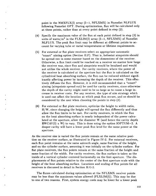
point in the NMXFLX(1) array (I=l, NFLXMX) in Namelist NLFLUX<br />
following Namelist OPT. During optimization, flux will be calculated only<br />
at these points, rather than at every point defined in step (2).<br />
Specify the maximum value of the flux at each point defined in step (3) in<br />
units of watts/m2 in the FLXLIM(1) array (I=l, NFLXMX) of Namelist<br />
NLFLUX. The peak flux limit may be different at different points to ac-<br />
count <strong>for</strong> varying tube or metal temperatures or lifetime requirements.<br />
For external or flat plate receivers select an appropriate automatic<br />
“smart” aiming option (Section 1I.F). That is, heliostat aimpoints should<br />
be spread out in some manner based on the dimensions of the receiver.<br />
Otherwise, a flux limit could be reached on a receiver no matter how large<br />
the receiver was, since flux and aimpoints would be localized and would<br />
not utilize the whole receiver. For cavity receivers, where the power of<br />
the receiver is calculated at the aperture but the flux is calculated on the<br />
cylindrical heat absorbing surface, the flux can be reduced without signif-<br />
icantly affecting power by increasing the depth of the receiver. This effec-<br />
tively diffuses the flux. However, it is still recommended that a “smart”<br />
aiming (aimpoints spread out) be used <strong>for</strong> cavity receivers, since otherwise<br />
the depth of the cavity might need to be so large as to cause a large in-<br />
crease in receiver costs. For any receiver, the type of aim strategy which<br />
is used can affect the location at which peak flux occurs, and so should be<br />
considered by the user when choosing the points in step (3).<br />
For external or flat plate receivers, optimize the height to width ratio,<br />
H/W, since changing the height will spread the flux differently and thus<br />
allow the flux limits to be met. For cavity receivers, in which the flux<br />
on the heat absorbing surface is nearly independent of the power calcu-<br />
lated at the aperture, allow the diameter W (and hence the cavity depth<br />
RWCAV(1) x W) to vary. This is done using the option IOPTUM=2. A<br />
deeper cavity will have a lower peak flux level <strong>for</strong> the same power at the<br />
aperture.<br />
receiver size is varied the flux points remain at the same relative posi-<br />
tion on the receiver surface, as illustrated in Figure IV-2. For external receivers,<br />
each flux point remains at the same azimuth angle, same fraction of the height,<br />
and on the cylinder surface, assuming it was initially on the cylinder surface. For<br />
flat plate receivers, the flux points remain at the same fraction of the height and<br />
same fraction of the width. For cavity receivers, the flux surface is taken as the<br />
inside of a vertical cylinder centered horizontally on the first aperture. The dis-<br />
placements of flux points relative to the center of the first aperture scale with the<br />
height of the heat absorbing surface. Locations and scaling of flux points <strong>for</strong> all<br />
receivers is discussed in detail in Section 1I.G-2.<br />
The fluxes calculated during optimization at the NFLXMX receiver points<br />
may be less than the maximum values allowed (FLXLIM(1)). This may be due<br />
to one of two reasons. First, system energy costs may be lower <strong>for</strong> a lower peak<br />
113


