I-LINE II Busway - Schneider Electric
I-LINE II Busway - Schneider Electric
I-LINE II Busway - Schneider Electric

Create successful ePaper yourself
Turn your PDF publications into a flip-book with our unique Google optimized e-Paper software.
BUSWAY AND WIRE<br />
MANAGEMENT SYSTEMS<br />
DE8<br />
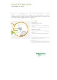
Power Zone <strong>Busway</strong>, Non-Segregated Bus<br />
Class 6090<br />
General Description<br />
Housing Construction: Ventilated or totally enclosed indoor or outdoor.<br />
Housing Material: Aluminum, steel, or stainless steel.<br />
Conductors: Silver plated copper or tin plated aluminum.<br />
Conductor Supports: Glass reinforced polyester or porcelain.<br />
Insulation: NORYL ® Tubing, epoxy, heat shrink tubing.<br />
POWER ZONETM metal-enclosed, non-segregated phase medium and low voltage<br />
bus systems are custom designed and manufactured. Standard sizes and<br />
ratings and a complete line of components allow each system to be tailored to suit<br />
the requirements of each application while at the same time providing the reliability<br />
that POWER ZONE name has stood for around the world for so many years.<br />
Standard bus systems are available in three basic voltage classes; 600V, 5000V<br />
and 15,000V with continuous self-cooled current ratings of 1200A, 1600A, 2000A,<br />
2500A, 3000A, 4000A, 5000A, and 6000A and momentary current ratings of<br />
60kA, 75kA, 80kA, 100kA, and 150kA RMS asymmetrical. Other voltage classes<br />
and current ratings are available upon request. Components such as equipment<br />
terminations, horizontal and vertical elbows, tee-taps, phase transportations, expansion<br />
joints, earthquake and vibration joints, misalignment joints, wall and floor<br />
penetration assemblies, fire and smoke barriers, bus supports, etc. are available<br />
for all sizes and ratings.<br />
POWER ZONETM bus design and construction is in strict accordance with ANSI<br />
Std. C37.23 and NEC Article 364. It can be supplied with full round edge 98%<br />
IACS copper or 57% IACS aluminum bars. Copper contact surfaces are silverplated.<br />
Aluminum contact are tinplated over a bronze strike by the Alstan-80A process<br />
and all aluminum electrical connections are fitted with conical washers to<br />
maintain a constant contact pressure.<br />
Standard hardware for conductor joints is zinc dichromated steel for bare connections<br />
not exposed to weather or insulated connections where the bus rating does<br />
not exceed 4000 amperes. Hardware is stainless steel for bare connections exposed<br />
to weather and all connection where the bus ratings exceeds 4000 amperes.<br />
With the exception of 600V class, which is normally uninsulated, the bus conductors<br />
are insulated with a slip-on extruded sleeve of track resistant, flame retardant,<br />
nonhygroscopic, high dielectric strength phenylene-oxide (NORYL ® EN-265) or<br />
liquid baked epoxy. Heat shrink tubing is also available.<br />
On 5000V bus and above, the conductor joints are insulated with tape to meet the<br />
required voltage rating, or when specifically required, insulated with flame retardant<br />
PVC insulating boots.<br />
The bus conductors are mounted and secured against short circuit forces in<br />
moulded, track resistant, flame retardant, non-hygroscopic support blocks of either<br />
glass reinforced polyester or high alumina ceramic material as required. The<br />
moulded support blocks are ribbed to maximize both tracking distance and mechanical<br />
strength. They are spaced as appropriate to maintain the required short<br />
circuit strength of the bus. Semi-conducting silicone rubber corona suppression<br />
inserts are used between the conductor and support blocks.<br />
The bus conductors are completely enclosed in a grounded metal housing for the<br />
protection of both personnel and property. The housings may be totally enclosed<br />
or ventilated depending on the type of installation and may be fabricated from<br />
painted aluminum, steel or stainless steel. Aluminum housings are standard and<br />
are recommended for current ratings above 2000A due to the deleterious effects<br />
of hysteresis associated with ferrous, magnetic housing materials such as steel.<br />
On outdoor applications, top covers are sloped to shed water and bottom covers<br />
are equipped with screened breathers to eliminate the accumulation of moisture<br />
within the housing. In addition, manually or thermostatically controlled electric<br />
strip heaters are provided to aid condensation control.<br />
To complete the system, a line of galvanized steel or aluminum structural supports<br />
is also available for both indoor outdoor applications.<br />
For additional ratings, contact <strong>Schneider</strong> sales office.<br />
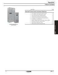
DE8-16<br />
Fitting Description<br />
• Non segregated phase bus<br />
• 600V thru 15kV (1200A - 4000A)s<br />
• Aluminum, steel, or stainless steel housing<br />
• Aluminum or copper bus bars<br />
• Insulated NORYL ® Tubing/Liquid-baked Epoxy or Heat Shrink Tubing (5kV -<br />
15kV)<br />
• Complete line of fittings provides for any configuration<br />
• Indoor trapeze and outdoor column supports<br />
• For use in utilities, industrial and commercial facilities<br />
POWER-ZONE bus is custom designed, manufactured and tested per ANSI<br />
C37.23 standards to meet customer specifications.The 600V product is also UL<br />
listed. It is a completely coordinated package of equipment with all the auxiliary<br />
material and supports for connecting transformers, switchgear, MCCís and motors,<br />
in all types of utility, industrial and commercial facilities.<br />
Transformer/Generator Connection — This type of termination should be used<br />
whenever the bus is connecting to a transformer, generator, motor, switch or any<br />
connection where the bus bars are connecting to porcelain mounted equipment<br />
terminals. It will include the same components as a flanged end plus one set of<br />
flexible braid type connectors and a terminal box (if required).<br />
Busing Box (Weatherhead) — A bushing box is used on service entrance run<br />
where the cable connection to the bus must be made via porcelain bushings. It is<br />
comprised of the same components as a transformer connection plus 3 through<br />
stud type apparatus bushings, bushing stud connectors (lug pads) and a strip<br />
heater.<br />
Ground Bus — The bus housing is designed and constructed to provide an electrically<br />
continuous ground path. The side rails of the bus housings are capable of<br />
carrying the full rated phase current continuously and, under short circuit conditions,<br />
are capable of carrying up to 60kA RMS asymmetrical fault current for 3seconds.<br />
Consequently, a separate ground bus is not necessary unless specified.<br />
Wall Entrance Seal — A wall entrance seal consists of a wall throat, wall flange<br />
(one side of wall only), and a barrier which prevents air or vapor from passing from<br />
one room to another or from outdoors to indoors. It also carries a 1/2 hour fire rating.<br />
Consult factory for higher fire ratings.<br />
Equipment Entrance Seal — An equipment entrance seal should be used whenever<br />
a barrier is required to prevent the passing of flame and/or gasses between<br />
the bus housing and the terminating equipment.<br />
Expansion Fittings — An expansion fitting is used to counteract the strain<br />
placed on the bus due to the expansion and contraction of the building or the bus<br />
itself. One should be used whenever the bus run crosses a building expansion<br />
joint and whenever a straight run of bus exceeds 60 feet.<br />
Flexible Housing (Misalignment) Collar — Required at terminations or wall<br />
penetrations when vibrations due to seismic forces may cause damage to the<br />
bus. It may also be used to adjust for the ìsettlingî of terminating equipment after<br />
installation.<br />
Flanged Ends — A flanged end is used to terminate the bus into switchgear, motor<br />
control centers, switchboards, or any rigid bus-to-bus connection. It consists<br />
of a gasketed equipment flange, up to 1' - 0" of 3P - 3W conductor (3P-4W as applicable),<br />
necessary insulation tapes, and required bolting hardware.<br />
Cable Tap Box — A cable tap box includes a gasketed and accessible termination<br />
box, lugs, necessary insulation tape (between bus and lugs only), and required<br />
bolting hardware. Lug sizes and quantity should be specified by purchaser.<br />
Supporting Steel (Hangers) — Supports should be added on the basis of one<br />
for every 10 ft. for indoor and one for every 12 ft. for outdoor. Indoor supports are<br />
a trapeze type hanger while outdoor supports are a single or double column type<br />
support. Consult factory for other type supports.Bus DuctHazardous Or Seismic<br />
Hazardous Or Seismic Locations — Consult factory for bus runs which are to<br />
be installed in a location which is classified as hazardous or in a Zone 3 or Zone<br />
4 seismic location.<br />
11/11