

gabion walls design gabion walls de - Modular Gabion Systems
gabion walls design gabion walls de - Modular Gabion Systems
gabion walls design gabion walls de - Modular Gabion Systems

You also want an ePaper? Increase the reach of your titles
YUMPU automatically turns print PDFs into web optimized ePapers that Google loves.
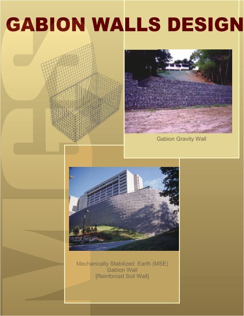
GABION WALLS DESIGN<br />
Mechanically Stabilized Earth (MSE)<br />
<strong>Gabion</strong> Wall<br />
[Reinforced Soil Wall]<br />
<strong>Gabion</strong> Gravity Wall
<strong>Gabion</strong> Walls Installation Gui<strong>de</strong><br />
Foundation<br />
Foundation Requirements, which must be established by the<br />
engineer, will vary with site conditions, height of <strong>gabion</strong><br />
structure, etc. Generally, the top layer of soil is stripped until a<br />
layer of the required bearing soil strength is reached. In some<br />
cases, the foundation may consist of suitable fill material<br />
compacted to a minimum of 95 percent of Proctor <strong>de</strong>nsity.<br />
Assembly<br />
To assemble each <strong>gabion</strong>, fold out the four si<strong>de</strong>s and the ends;<br />
fold adjacent si<strong>de</strong>s up and join edges with spiral bin<strong>de</strong>rs; insert<br />
diaphragms at 3-foot centers and fasten them to the base panel<br />
with spiral bin<strong>de</strong>rs. Place the empty <strong>gabion</strong>s in the <strong><strong>de</strong>sign</strong>ed<br />
pattern on the foundation. When the entire first course is in<br />
position, permanently secure adjacent <strong>gabion</strong>s by installing<br />
vertical spiral bin<strong>de</strong>rs running full height at all corners.<br />
Similarly secure both edges of all diaphragms with spiral<br />
bin<strong>de</strong>rs. Crimp ends of all spiral bin<strong>de</strong>rs. Corner stiffeners are<br />
then installed diagonally across the corners on 1-foot centers<br />
(not used for <strong>gabion</strong>s less than 3-feet high). The stiffeners must<br />
be hooked over crossing wires and crimped closed at both ends.<br />
Final <strong>gabion</strong> alignment must be checked before filling begins.<br />
Filling<br />
Fill material must be as specified by the engineer. It must have<br />
suitable compressive strength and durability to resist the<br />
loading, as well as the effects of water and weathering. Usually,<br />
3 to 8-inch clean, hard stone is specified. A well gra<strong>de</strong>d stonefill<br />
increases <strong>de</strong>nsity. Place the stone in 12-inch lifts with power<br />
equipment, but distribute evenly by hand to minimize voids and<br />
ensure a pleasing appearance along the exposed faces. Keep<br />
baskets square and diaphragms straight. The fill in adjoining<br />
cells should not vary in height by more than 1-foot. Level the<br />
final stone layer allowing the diaphragms’ tops to be visible.<br />
Lower lids and bind along all <strong>gabion</strong>s’ edges and at diaphragms’<br />
tops with spiral bin<strong>de</strong>rs. Alternatively, tie or lacing wire can be<br />
utilized for this operation.<br />
Successive Courses<br />
Place the next course of assembled empty <strong>gabion</strong>s on top of the<br />
filled course. Stagger the joints so that the vertical connections<br />
are offset from one another. Bind the empty baskets to the filled<br />
ones below the spirals or tie wire at all external bottom edges.<br />
Bind vertical edges together with spiral bin<strong>de</strong>rs and continue<br />
with the same steps as for the first layer. Successive courses are<br />
placed in like manner until the structure is complete.<br />
<strong>Gabion</strong> Walls Design Gui<strong>de</strong><br />
Gravity Wall Design<br />
<strong>Gabion</strong> Walls are generally analyzed as gravity retaining <strong>walls</strong>,<br />
that is, <strong>walls</strong> which use their own weight to resist the lateral<br />
earth pressures. The use of horizontal layers of wel<strong>de</strong>d wire<br />
mesh (Anchor Mesh) as horizontal tie-backs for soil<br />
reinforcement (MSE Walls) is discussed separately. This<br />
material is presented for the use of a qualified engineer familiar<br />
with traditional procedures for retaining wall <strong><strong>de</strong>sign</strong>.<br />
<strong>Gabion</strong> <strong>walls</strong> may be stepped on either the front or the back (soil<br />
si<strong>de</strong>) face as illustrated in Figure 1. The <strong><strong>de</strong>sign</strong> of both types is<br />
based on the same principles.<br />
Design begins with the selection of trail dimensions for a typical<br />
vertical cross section through the wall. Four main steps must<br />
then be followed:<br />
1. Determine the forces acting on the wall.<br />
2. Check that resisting moment exceeds the overturning<br />
moment by a suitable safety factor.<br />
3. Check that sliding resistance exceeds the active<br />
horizontal force by a suitable safety factor.<br />
4. Check that the resultant force falls within the middle<br />
third of the wall’s base, and that the maximum bearing<br />
pressure is within the allowable limit.<br />
These steps are repeated iteratively until a suitable <strong><strong>de</strong>sign</strong> that<br />
meets all criteria is achieved. The wall stability must be<br />
checked at the base and at each course. Pertinent equations are<br />
given below, and an application is illustrated in Example 1.<br />
Mechanically Stabilized Earth (MSE)<br />
Walls Soil Reinforcement<br />
When required, flat layers of wel<strong>de</strong>d wire mesh (Anchor Mesh)<br />
are specified as soil reinforcement to secure the <strong>gabion</strong> wall into<br />
the backfill. In such cases, the Anchor Mesh must be joined<br />
securely to the <strong>gabion</strong> wall facing with spirals or tie wire at the<br />
specified elevations as layers of backfill are placed and<br />
compacted.<br />
Rev. 11/04 Page 1 of 12 <strong>Modular</strong> <strong>Gabion</strong> <strong>Systems</strong>
Forces Acting on the Wall<br />
As shown in Figure 1, the main forces acting on <strong>gabion</strong> <strong>walls</strong><br />
are the vertical forces from the weight of the <strong>gabion</strong>s and the<br />
lateral earth pressure acting on the back face. These forces are<br />
used herein to illustrate the main <strong><strong>de</strong>sign</strong> principles. If other<br />
forces are encountered, such as vehicular loads or seismic loads,<br />
they must also be inclu<strong>de</strong>d in the analysis.<br />
The weight of a unit length (one foot) of wall is simply the<br />
product of the wall cross section and the <strong>de</strong>nsity of the <strong>gabion</strong><br />
fill. The latter value may be conservatively taken as 100 lb/ft 3<br />
for typical material (Wg ).<br />
The lateral earth pressure is usually calculated by the Coulomb<br />
equation. Although based on granular material, it is<br />
conservative for cohesive material. According to Coulomb<br />
theory, the total active force of the triangular pressure<br />
distribution acting on the wall is:<br />
P<br />
2<br />
a = Kaws<br />
H / 2<br />
GRAVITY WALLS<br />
Equation 1<br />
Where ws is the soil <strong>de</strong>nsity, H is the wall height, and Ka is the<br />
coefficient of active soil pressure. The soil <strong>de</strong>nsity is often<br />
taken as 120 lb/ft3 where a specific value is not available.<br />
If a uniformly distributed surcharge pressure (q) is present on<br />
top of the backfill surface, it may be treated as an equivalent<br />
layer of soil that creates a uniform pressure over the entire<br />
height of the wall. Equation 1 is modified to:<br />
P<br />
2<br />
a = K a(<br />
ws<br />
H / 2 + qH)<br />
The pressure coefficient is Ka is given by:<br />
K a<br />
=<br />
Where:<br />
2<br />
cos<br />
Equation 1A<br />
cos<br />
2<br />
( φ − β )<br />
2<br />
⎡ sin( φ + δ)<br />
sin( φ − α ) ⎤<br />
β cos( δ + β ) ⎢1+<br />
⎥<br />
⎢⎣<br />
cos( δ + β ) cos( α − β ) ⎥⎦<br />
α = slope angle of backfill surface<br />
Equation 2<br />
β = acute angle of back face slope with vertical (-value<br />
where as in Fig. 1A; + value when as in Fig. 1B)<br />
δ = angle of wall friction<br />
φ<br />
= angle of internal friction of soil<br />
Pa is inclined to a line normal to the slope of the back face by<br />
the angle δ . However, because the effect of wall friction is<br />
small, δ is usually taken as zero. Typical values of φ for<br />
various soils are given in Table I. Values of Ka for various<br />
combinations of ß, δ , and α are given in Table II.<br />
The horizontal component of Pa is:<br />
P h = Pa<br />
cosβ<br />
Equation 3<br />
The vertical component of Pa is usually neglected in <strong><strong>de</strong>sign</strong><br />
because it reduces the overturning moment and increases the<br />
sliding resistance.<br />
Overturning Moment Check<br />
The active soil pressure forces tend to overturn the wall, and this<br />
must be properly balanced by the resisting moment <strong>de</strong>veloped<br />
from the weight of the wall and other forces. Using basic<br />
principles of statics, moments are taken about the toe of the wall<br />
to check overturning.<br />
This check may be expressed as<br />
M r ≥ SFoM<br />
o<br />
Equation 4<br />
Where Mr is the resisting moment, Mo is the overturning<br />
moment, and SFo is the safety factor against overturning<br />
(typically 2.0). Each moment is obtained by summing the<br />
products of each appropriate force times its perpendicular<br />
distance the toe of the wall.<br />
Neglecting wall friction, the active earth force acts normal to the<br />
slope of the back face at a distance H/3 above the base. When a<br />
surcharge is present, the distance of the total active force above<br />
the toe becomes<br />
H(<br />
H + 3q<br />
/ w )<br />
d<br />
s<br />
a =<br />
+ B sin β<br />
3(<br />
H + 2q<br />
/ ws<br />
)<br />
The overturning moment is<br />
M o=<br />
d aPh<br />
Equation 5<br />
Equation 6<br />
The weight of the <strong>gabion</strong> wall (Wg ) acts vertically through the<br />
centroid of its cross section area. The horizontal distance to this<br />
point from the toe of the wall (dg ) may be obtained from the<br />
statical moment of wall areas. That is, moments of areas about<br />
the toe are taken, then divi<strong>de</strong>d by the total area, as shown in<br />
Example 1.<br />
Rev. 11/04 Page 2 of 12 <strong>Modular</strong> <strong>Gabion</strong> <strong>Systems</strong>
The resisting moment is the sum of the products of vertical<br />
forces or weights per unit length (W) and their distance (d) from<br />
the toe of the wall:<br />
M r = ∑ dW<br />
Equation 7<br />
For the simple gravity wall, the resisting moment is provi<strong>de</strong>d<br />
entirely by the weight of the wall and<br />
M r = dgWg<br />
Sliding Resistance Check<br />
Equation 7A<br />
The ten<strong>de</strong>ncy of the active earth pressure to cause the wall to<br />
sli<strong>de</strong> horizontally must be opposed by the frictional resistance at<br />
the base of the wall. This may be expressed as<br />
μWv<br />
≥ SFsPh<br />
Equation 8<br />
Where μ is the coefficient of the sliding friction (tan of angle of<br />
friction of soil), Wv is the sum of the vertical forces (Wg in this<br />
case), and SFs is the safety factor against sliding (typically 1.5).<br />
Check Bearing Pressure<br />
First check to <strong>de</strong>termine if the resultant vertical force lies within<br />
the middle third of the base. If B <strong>de</strong>notes the width of the base,<br />
the eccentricity, e, of the vertical force from the midwidth of the<br />
base is<br />
e = B/2 - (M r - Mo)/Wv<br />
For the resultant force to lie in the middle third:<br />
− B / 6 ≤ e ≤ B<br />
/ 6<br />
The maximum pressure un<strong>de</strong>r the base, P, is then<br />
P = ( Wv<br />
/ B)(<br />
1+<br />
6e<br />
/ B)<br />
Equation 9<br />
Equation 10<br />
Equation 11<br />
The maximum pressure must not exceed the allowable soil<br />
bearing pressure, Pb :<br />
P ≤ Pb<br />
The safety factor must be inclu<strong>de</strong>d in Pb .<br />
Equation 12<br />
Example 1:<br />
Given Data (Refer to Cross Section, page 5)<br />
Wall Height………………………. H = 9 ft<br />
Surcharge…………………………. q = 300 psf<br />
Backfill slope angle………………. α = 0 <strong>de</strong>g<br />
Back Face slope angle…………….<br />
Soil friction angle………………… φ<br />
Rev. 11/04 Page 3 of 12 <strong>Modular</strong> <strong>Gabion</strong> <strong>Systems</strong><br />
β<br />
= -6 <strong>de</strong>g<br />
= 35 <strong>de</strong>g<br />
Soil <strong>de</strong>nsity……………………….. ws = 120 pcf<br />
<strong>Gabion</strong> fill <strong>de</strong>nsity………………... wg = 100 pcf<br />
Soil bearing pressure……………... Pb = 4000 psf<br />
Determine if safety factors are within limits:<br />
Pressure coefficient from Equation 2 is Ka =0.23<br />
Active earth force, Pa , from Equation 1A is<br />
Pa<br />
= 0.<br />
23(<br />
120 x9<br />
2<br />
+ 300 x9)<br />
= 1,<br />
739lb<br />
/ ft<br />
Horizontal component from Equation 3 is<br />
Ph<br />
= 1739<br />
cos6<br />
= 1,<br />
730 lb/<br />
ft<br />
Vertical distance to Ph from Equation 5 is<br />
da<br />
9(<br />
9 + 3×<br />
300 / 120)<br />
=<br />
3(<br />
9 + 2 × 300 / 120 )<br />
= 2.<br />
91 ft<br />
+ 6sin(<br />
−6)<br />
Overturning moment from Equation 6 is<br />
Mo<br />
= 2.<br />
91 × 1730<br />
= 5034 ft − lb/<br />
ft<br />
Weight of <strong>gabion</strong>s for a 1-ft unit length is<br />
W<br />
g<br />
=<br />
( 18<br />
+<br />
13.<br />
5<br />
= 40.<br />
5×<br />
100<br />
= 4050 lb/<br />
ft<br />
+<br />
9)<br />
100<br />
Horizontal distance to Wg is<br />
dg =<br />
ΣAx<br />
/ ΣA<br />
⎡18(<br />
3cos6<br />
+ 1.<br />
5sin<br />
6)<br />
+ 13 . 5(<br />
3.<br />
75 cos6⎤<br />
= ⎢<br />
⎥ / 40.<br />
5<br />
⎣+<br />
4.<br />
5sin<br />
6)<br />
+ 9(<br />
4.<br />
5cos6<br />
+ 7.<br />
5sin<br />
6)<br />
⎦<br />
= 3.<br />
96 ft
Resisting moment from Equation 7 is<br />
M r<br />
= 3.<br />
96x4050<br />
= 16,<br />
038 ft − lb / ft<br />
Safety factor against overturning from Equation 4 is<br />
SFo<br />
= M r / M o<br />
= 16.<br />
038 / 5034<br />
=<br />
3.<br />
19<br />
><br />
2.<br />
00<br />
Safety factor against sliding from Equation 8 is<br />
SFs = μWg<br />
/ Ph<br />
= tan 35x4050<br />
=<br />
1.<br />
64<br />
><br />
1.<br />
50<br />
/ 1730<br />
OK<br />
OK<br />
Reaction eccentricity from Equation 9 is<br />
e = 6/<br />
2 − ( 16038 − 5034 ) / 4050<br />
Rev. 11/04 Page 4 of 12 <strong>Modular</strong> <strong>Gabion</strong> <strong>Systems</strong><br />
=<br />
0.<br />
283<br />
ft<br />
Limit of eccentricity from Equation 10 is<br />
− 1 ≤ e ≤ 1ft<br />
Maximum base pressure from Equation 11 is<br />
p = ( 4050 / 6)(<br />
1 + 6x.<br />
283 / 6)<br />
= 866 psf < 4000 psf<br />
OK<br />
OK<br />
All safety factors are within limits. Stability checks at<br />
intermediate levels in the <strong>walls</strong> show similar results.
Rev. 11/04 Page 5 of 12 <strong>Modular</strong> <strong>Gabion</strong> <strong>Systems</strong>
Rev. 11/04 Page 6 of 12 <strong>Modular</strong> <strong>Gabion</strong> <strong>Systems</strong>
To increase the efficiency of MSE <strong>gabion</strong> <strong>walls</strong>, layers of wire<br />
mesh (Anchor Mesh) may be attached to the back face and<br />
embed<strong>de</strong>d in the backfill. The Anchor Mesh layers in this<br />
reinforced soil wall will resist the active soil force, by a<br />
combination of friction on the wire surface and mechanical<br />
interlock with the soil. Reinforced soil <strong>walls</strong> generally use a<br />
single thickness of <strong>gabion</strong>s. Design consists of (1) <strong>walls</strong><br />
stability checks similar to that for gravity <strong>walls</strong>, assuming the<br />
<strong>gabion</strong>s and the reinforced soil act together as one unit, and (2)<br />
checks for strength and pullout resistance of the reinforcement<br />
layers, to ensure such action. The consi<strong>de</strong>rations that differ<br />
from gravity wall <strong><strong>de</strong>sign</strong> are discussed below.<br />
Walls will typically be 6 <strong>de</strong>grees from vertical. To simplify<br />
calculations, assume wall is vertical for certain calculations as<br />
indicated in Example 2.<br />
In checking overturning, sliding and bearing, the weight of the<br />
soil in the reinforced zone is inclu<strong>de</strong>d with the weight of the<br />
wall.<br />
The tensile force in each layer of reinforcement is assumed to<br />
resist the active earth force over an incremental height of wall.<br />
Its calculated value must be limited to the tensile strength of the<br />
mesh divi<strong>de</strong>d by the safety factor (typically 1.85). Therefore:<br />
3000/1.85=1620 lb/ft.<br />
As in gravity wall <strong><strong>de</strong>sign</strong>, the wall is <strong><strong>de</strong>sign</strong>ed to resist the force<br />
generated by a sliding wedge of soil as <strong>de</strong>fined by Coulomb.<br />
The reinforcement at each layer must ext end past the wedge by<br />
at least 3-feet, and by a distance sufficient to provi<strong>de</strong> anchorage<br />
in the adjacent soil. Generally, this results in a B distance 0.5 to<br />
0.7 times the height of the wall.<br />
Additional equations used in the <strong><strong>de</strong>sign</strong> of MSE <strong>walls</strong>, <strong>de</strong>rived<br />
from statics are given in Example 2.<br />
Example 2:<br />
Given Data (See Cross Section, page 10)<br />
Wall Height…………… H = 24 ft (21 ft+3 ft embedment)<br />
Wall Thickness………… T = 3 ft<br />
Surcharge……………… Q = 300 psf<br />
Backfill slope angle…… α = 0 <strong>de</strong>g<br />
Back Face slope angle…<br />
β =<br />
Soil friction angle……… φ =<br />
-6 <strong>de</strong>g<br />
35 <strong>de</strong>g<br />
Soil <strong>de</strong>nsity…………… Ws = 120 pcf<br />
<strong>Gabion</strong> fill <strong>de</strong>nsity…… Wg = 100 pcf<br />
Soil bearing pressure… Pb = 4000 psf<br />
(1) Determine if safety factors are within limits:<br />
Reinforced Soil Walls<br />
The trial value for dimension B was selected as 16.5<br />
approximately 0.7H. Also see note near the end of part 2 below<br />
on trial selection of B to provi<strong>de</strong> a<strong>de</strong>quate embedment length.<br />
In these calculations, positive values are used for the sin and tan<br />
of β and the sign in the equation changed as necessary.<br />
Pressure coefficient from Equation 2 is Ka =0.23<br />
Active earth force, Pa , from Equation 1A is<br />
= 9605lb/<br />
ft<br />
Rev. 11/04 Page 7 of 12 <strong>Modular</strong> <strong>Gabion</strong> <strong>Systems</strong><br />
Pa<br />
= 0.<br />
23(<br />
120 × 24<br />
2<br />
/ 2 + 300 × 24)<br />
Vertical distance to Pa from Equation 5 is<br />
da<br />
24(<br />
24 + 3×<br />
300 / 120 )<br />
=<br />
3(<br />
24 + 2 × 300 / 120 )<br />
= 9.<br />
22 ft<br />
Overturning moment from Equation 6 is<br />
M o<br />
= 9.<br />
22 × 9605<br />
=<br />
88,<br />
600<br />
Weight of <strong>gabion</strong>s is<br />
W<br />
g<br />
= 7200 lb/<br />
ft<br />
ft − lb / ft<br />
= ( 3×<br />
24 × 100<br />
Horizontal distance to Wg is<br />
d<br />
g<br />
= t / 2 + ( H / 2)<br />
tan β<br />
=<br />
=<br />
3/<br />
2<br />
2.<br />
76<br />
+<br />
ft<br />
Weight of surcharge is<br />
Wg<br />
= qb<br />
= 3290lb<br />
/ ft<br />
( 24 / 2)<br />
tan6<br />
= q(<br />
B − t − H tan β )<br />
=<br />
=<br />
300(<br />
1.<br />
65<br />
300(<br />
10.<br />
98)<br />
Horizontal distance to Wq is<br />
dq<br />
− 3 − 24 tan 6)<br />
= b / 2 + H tan β + t<br />
= 10.<br />
98 / 2 + 24 tan 6 + 3<br />
= 11.<br />
01 ft<br />
Weight of soil wedge is<br />
Ws<br />
= ( H tan β<br />
/ 2 + b)<br />
Hws<br />
= ( 24 tan6<br />
/ 2 + 10.<br />
98)<br />
24x120<br />
=<br />
35,<br />
250lb/<br />
ft
Horizontal distance to Ws is<br />
d s<br />
⎡<br />
( H<br />
2<br />
tan )( H tan / 3 t)<br />
( Hb)<br />
⎤<br />
=<br />
β β + +<br />
⎢<br />
⎥ws<br />
/ Ws<br />
⎢⎣<br />
( b / 2 + H tan β + t)<br />
⎥⎦<br />
⎡(<br />
24<br />
2<br />
tan 6)(<br />
24 tan6<br />
/ 3 + 3)<br />
+ ( 24 x10<br />
. 98)<br />
⎤<br />
= ⎢<br />
⎥<br />
⎢⎣<br />
( 10 . 98 / 2 + 24 tan 6 + 3)<br />
⎥⎦<br />
= 10.<br />
67 ft<br />
Resisting moment from Equation 7 is<br />
M r<br />
= Ws<br />
ds<br />
+ Wg<br />
dg<br />
+ W qdq<br />
=<br />
=<br />
35,<br />
250<br />
×<br />
432,<br />
200<br />
10.<br />
67<br />
ft − lb / ft<br />
120<br />
35250<br />
+ 7200 × 2.<br />
76 + 3290 × 11.<br />
01<br />
Safety factor against overturning from Equation 4 is<br />
SFo<br />
= M r / M o<br />
= 432 , 200 / 88,<br />
600<br />
=<br />
4.<br />
88<br />
><br />
2.<br />
00<br />
Total vertical weight is<br />
Wv<br />
= Ws<br />
+ Wg<br />
+ W q<br />
= 35,<br />
250 + 7200 + 3290<br />
= 45,<br />
740lb<br />
/ ft<br />
Safety factor against sliding from Equation 8 is<br />
SFs = μWv<br />
/ Ph<br />
= tan 35 × 45,<br />
740 / 9605<br />
=<br />
3.<br />
33<br />
><br />
1.<br />
50<br />
Reaction eccentricity from Equation 9 is<br />
e = 16.<br />
5 / 2 − ( 432,<br />
200 − 88,<br />
600)<br />
45,<br />
740<br />
=<br />
0.<br />
738<br />
ft<br />
Limit of eccentricity from Equation 10 is<br />
−2.<br />
75 ≤ e ≤ 2.<br />
75 ft<br />
Maximum base pressure from Equation 11 is<br />
p = ( 45,<br />
740 / 16.<br />
5)(<br />
1+<br />
6×<br />
0.<br />
738 / 16.<br />
5)<br />
= 3520 psf < 4000 psf<br />
OK<br />
OK<br />
OK<br />
OK<br />
All safety factors are within limits. Stability checks at<br />
intermediate levels in the <strong>walls</strong> show similar results.<br />
(2) Determine if reinforcement mesh is satisfactory<br />
The pressure on any layer a distance z (ft) below the surface is<br />
= ws<br />
z + q<br />
= 120 z + 300 psf<br />
Rev. 11/04 Page 8 of 12 <strong>Modular</strong> <strong>Gabion</strong> <strong>Systems</strong><br />
fv<br />
The tensile strength on any layer of reinforcement in a vertical<br />
segment of soil of thickness Sv (ft), centered about the<br />
reinforcement layer, is<br />
T = Sv<br />
Ka<br />
fv<br />
= 0.<br />
23 Sv<br />
fv<br />
Calculate T for each layer as follows<br />
z (ft) Sv (ft) Fv (psf) T (lb/ft) T
The minimum embedment length past the wedge to provi<strong>de</strong> a<br />
safety factor of 1.5 against pullout in any layer is<br />
Lem = 1. 5T<br />
/( 2Γfv<br />
tanφ)<br />
Where Γ is a “scale correction factor” assumed as 0.65.<br />
Lem<br />
= 1.<br />
5T<br />
/( 2x0.<br />
65<br />
= 1.<br />
65T<br />
/<br />
fv<br />
fv<br />
tan 35)<br />
At the top of the wall, the distance, X, to the wedge failure plane<br />
from the back of the wall is<br />
X = H tan( 45 − φ / 2)<br />
− H tan β<br />
= 24 tan( 27.<br />
5)<br />
− 24<br />
=<br />
11.<br />
54<br />
ft<br />
tan( 6)<br />
At any layer, the length of embedment past the wedge is<br />
Le<br />
= B − t − X ( H − z)<br />
/ H<br />
= 16.<br />
5 − 3 −11<br />
. 54(<br />
24 − z)<br />
/ 24<br />
= 1.<br />
956 +<br />
0.<br />
481<br />
z<br />
[Note: Le can be calculated for the top layer of reinforcement<br />
initially, when selecting B, to make sure it is at least 3-feet. If<br />
not, increase B for the trial <strong><strong>de</strong>sign</strong>.]<br />
Calculate Le and Lem for each layer as follows:<br />
z (ft) Fv (psf) T (lb/ft)<br />
Le (ft) Lem (ft) Le >Lem ?<br />
Rev. 11/04 Page 9 of 12 <strong>Modular</strong> <strong>Gabion</strong> <strong>Systems</strong><br />
3<br />
6<br />
9<br />
12<br />
15<br />
18<br />
19.5<br />
21<br />
22.5<br />
24<br />
660<br />
1020<br />
1380<br />
1740<br />
2100<br />
2460<br />
2640<br />
2820<br />
3000<br />
3180<br />
683<br />
704<br />
952<br />
1200<br />
1449<br />
1273<br />
911<br />
973<br />
1035<br />
549<br />
3.40<br />
4.84<br />
6.29<br />
7.73<br />
9.17<br />
10.62<br />
11.34<br />
12.06<br />
12.78<br />
13.50<br />
1.71<br />
1.14<br />
1.14<br />
1.14<br />
1.14<br />
0.85<br />
0.59<br />
0.59<br />
0.59<br />
0.28<br />
The embed<strong>de</strong>d length of reinforcement in each layer is greater<br />
than the minimum required for pullout and is also at least 3-feet.<br />
Reinforcement <strong><strong>de</strong>sign</strong> is satisfactory with mesh ad<strong>de</strong>d at the<br />
19.5 and 22.5-foot levels.<br />
General Note: Every effort has been ma<strong>de</strong> to ensure the<br />
accuracy and reliability of the information presented herein.<br />
Nevertheless, the user of this brochure is responsible for<br />
checking and verifying the data by in<strong>de</strong>pen<strong>de</strong>nt means.<br />
Application of the information must be based on responsible<br />
professional judgment. No express warranties of merchantability<br />
or fitness are created or inten<strong>de</strong>d by this document. Specification<br />
data referring to mechanical and physical properties and chemical<br />
analyses related solely to test performed at the time of<br />
manufacture in specimens obtained from specific locations of the<br />
product in accordance with prescribed sampling procedures.<br />
Y<br />
Y<br />
Y<br />
Y<br />
Y<br />
Y<br />
Y<br />
Y<br />
Y<br />
Y
Rev. 11/04 Page 10 of 12 <strong>Modular</strong> <strong>Gabion</strong> <strong>Systems</strong>
Table I<br />
Angles of Internal Friction and Unit Weights of Soil*<br />
Angle of Internal Friction<br />
Soil Type Soil Condition (<strong>de</strong>g)<br />
φ Soil Density, w (lb/ft 3 )<br />
Course sand, sand & gravel<br />
Medium sand<br />
Fine silty sand, sandy silt<br />
Uniform silt<br />
Compact soil<br />
Loose<br />
Compact soil<br />
Loose<br />
Compact soil<br />
Loose<br />
Compact soil<br />
Loose<br />
Clay-silt Soft/medium 20 90/120<br />
Silty clay Soft/medium 15 90/120<br />
Clay Soft/medium 0/10 90/120<br />
*F.S. Merritt, Ed., “Standard Handbook for Civil Engineers” McGraw-Hill, 1983<br />
Rev. 11/04 Page 11 of 12 <strong>Modular</strong> <strong>Gabion</strong> <strong>Systems</strong><br />
40<br />
35<br />
40<br />
30<br />
30<br />
25<br />
30<br />
25<br />
140<br />
90<br />
130<br />
90<br />
130<br />
85<br />
135<br />
85
Table II<br />
Active Pressure Coefficient, Ka<br />
β α φ = 10 φ = 15 φ = 20 φ = 25 φ = 30 φ = 35 φ = 40<br />
-6 0 0.68 0.56 0.45 0.37 0.29 0.23 0.18<br />
-6 5 0.74 0.6 0.49 0.39 0.31 0.24 0.19<br />
-6 10 0.94 0.67 0.53 0.42 0.33 0.26 0.2<br />
-6 15 0.89 0.59 0.46 0.35 0.27 0.21<br />
-6 20 0.82 0.52 0.39 0.29 0.22<br />
-6 25 0.75 0.44 0.32 0.24<br />
-6 30 0.67 0.37 0.26<br />
-6 35 0.58 0.3<br />
-6 40 0.49<br />
0 0 0.7 0.59 0.49 0.41 0.33 0.27 0.22<br />
0 5 0.77 0.63 0.52 0.43 0.35 0.28 0.23<br />
0 10 0.97 0.7 0.57 0.46 0.37 0.3 0.24<br />
0 15 0.93 0.64 0.5 0.4 0.32 0.25<br />
0 20 0.88 0.57 0.44 0.34 0.27<br />
0 25 0.82 0.5 0.38 0.29<br />
0 30 0.75 0.44 0.32<br />
0 35 0.67 0.37<br />
0 40 0.59<br />
5 0 0.73 0.62 0.52 0.44 0.37 0.31 0.25<br />
5 5 0.8 0.67 0.56 0.47 0.39 0.32 0.26<br />
5 10 1 0.74 0.61 0.5 0.41 0.34 0.28<br />
5 15 0.98 0.68 0.55 0.45 0.36 0.29<br />
5 20 0.94 0.62 0.49 0.39 0.31<br />
5 25 0.89 0.56 0.43 0.34<br />
5 30 0.83 0.5 0.37<br />
5 35 0.76 0.43<br />
5 40 0.68<br />
10 0 0.76 0.65 0.56 0.48 0.41 0.34 0.29<br />
10 5 0.83 0.7 0.6 0.51 0.43 0.36 0.3<br />
10 10 1.05 0.78 0.65 0.55 0.46 0.38 0.32<br />
10 15 1.04 0.74 0.6 0.5 0.41 0.34<br />
10 20 1.02 0.68 0.55 0.44 0.36<br />
10 25 0.98 0.63 0.49 0.39<br />
10 30 0.92 0.57 0.43<br />
10 35 0.86 0.5<br />
10 40 0.79<br />
15 0 0.79 0.69 0.6 0.52 0.45 0.39 0.33<br />
15 5 0.87 0.75 0.65 0.56 0.48 0.41 0.35<br />
15 10 1.1 0.83 0.71 0.6 0.51 0.43 0.37<br />
15 15 1.11 0.8 0.66 0.55 0.47 0.39<br />
15 20 1.1 0.75 0.61 0.51 0.42<br />
15 25 1.08 0.7 0.56 0.45<br />
15 30 1.04 0.65 0.5<br />
15 35 0.98 0.58<br />
15 40 0.91<br />
Rev. 11/04 Page 12 of 12 <strong>Modular</strong> <strong>Gabion</strong> <strong>Systems</strong>
<strong>Modular</strong> <strong>Gabion</strong> <strong>Systems</strong><br />
A Division of C. E. Shepherd Company<br />
2221 Canada Dry Street<br />
Houston TX 77023<br />
800.324.8282 • 713.924.4371<br />
www.<strong>gabion</strong>s.net