P7.1.2.2 - LD DIDACTIC
P7.1.2.2 - LD DIDACTIC
P7.1.2.2 - LD DIDACTIC

Create successful ePaper yourself
Turn your PDF publications into a flip-book with our unique Google optimized e-Paper software.
0808-Ste<br />
Solid-state physics<br />
Properties of crystals<br />
X-ray structural analysis<br />
Objects of the experiment<br />
Evaluating the Laue diagrams of an NaCl and an LiF monocrystal.<br />
Principles<br />
Investigating the symmetry and lattice structure of both crystals.<br />
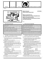
Fig. 1 Scheme of the setup for taking a Laue diagram of a monocrystal<br />
a X-ray tube<br />
b Collimator<br />
c Crystal<br />
d X-ray film<br />
In 1912, Max von Laue proposed to provide evidence for the<br />
supposed wave character of X-rays by diffraction at crystals.<br />
Friedrich and Knipping took up his proposal and exposed a<br />
crystal to a collimated ray from an X-ray tube. On a photographic<br />
plate behind the crystal they observed – as expected<br />
– discrete reflections. For the first time they also confirmed the<br />
spatial lattice structure of crystalline substances with this<br />
experiment.<br />
Laue condition:<br />
In his interpretation of these findings, von Laue considered the<br />
crystal to be a lattice built up of three groups of one-dimensional<br />
equidistant rows of points. When an X-ray is diffracted<br />
at a row of points,<br />
� = �1 − �2 = a0 ⋅ cos �1 − a0 ⋅ cos �2 (I)<br />
a0: distance between the points<br />
�1: angle between the incoming X-ray and the row of points<br />
�2: angle between the diffracted X-ray and the row of points<br />
is the difference of path of partial rays scattered at two neighbouring<br />
points (lattice elements, see Fig. 2). There is construc-<br />
1<br />
<strong>LD</strong><br />
Physics<br />
Leaflets<br />
<strong>P7.1.2.2</strong><br />
Laue diagrams:<br />
investigating the lattice structure of<br />
monocrystals<br />
Fig. 2 Two-dimensional representation for calculating the difference<br />
of path ∆ = ∆1 − ∆2 between two neighbouring X-rays<br />
which are diffracted at a row of points in a cubic crystal.<br />
tive interference between the partial rays if � in an integer<br />
multiple of the wavelength �. This condition has to be fulfilled<br />
in all three spatial directions.<br />
In a cubic crystal, the rows of points associated with the three<br />
spatial directions are all perpendicular to each other the distance<br />
a0 between the points always being the same. The Laue<br />
condition for constructive interference therefore reads:<br />
a0 ⋅ cos �1 − a0 ⋅ cos �2 = h ⋅ �<br />
a0 ⋅ cos �1 − a0 ⋅ cos �2 = k ⋅ �<br />
a0 ⋅ cos �1 − a0 ⋅ cos �2 = l ⋅ � (II)<br />
with integer values of h, k, l<br />
Here � 1, � 1 and � 1 are the angles between the incoming ray<br />
and the rows of points whereas � 2, � 2 and � 2 are the angles<br />
between the diffracted ray and the rows of points. The quantities<br />
h, k, l are called Laue or extended Miller indices. As they<br />
are small integer numbers, the Laue condition cannot be<br />
fulfilled for arbitrary wavelengths �, but only for particular<br />
(“appropriate”) ones.
<strong>P7.1.2.2</strong> <strong>LD</strong> Physics Leaflets<br />
Apparatus<br />
1 X-ray apparatus . . . . . . . . . . . . . .<br />
or<br />
554 811<br />
1 X-ray apparatus . . . . . . . . . . . . . . 554 812<br />
1 X-ray film holder . . . . . . . . . . . . . 554 838<br />
1 filmpack 2 (X-ray film) . . . . . . . . . . . 554 892<br />
1 LiF crystal for Laue diagrams . . . . . . . 554 87<br />
1 NaCl crystal for Laue diagrams . . . . . . 554 88<br />
The unit vectors<br />
s1 = ⎛cos �<br />
⎝<br />
1,cos �1,cos �1⎞ ⎠<br />
and<br />
s2 = ⎛cos �<br />
⎝<br />
2,cos �2,cos �2⎞ (III)<br />
⎠<br />
are frequently introduced. They point in the direction of the<br />
incoming X-ray and the outgoing X-ray, respectively. The Laue<br />
condition (II) then takes the form<br />
s1 − s2 = � ⋅ G with G = (h, k, l) ⋅ 1<br />
(IV).<br />
a0 G is called the vector of the reciprocal lattice. The Laue<br />
condition is fulfilled if h, k and l are integers.<br />
Bragg condition:<br />
As s 1 and s 2 are unit vectors, they have equal magnitudes.<br />
Therefore the vector G is perpendicular to the bisectrix S<br />
Safety notes<br />
The X-ray apparatus fulfils all regulations governing an<br />
X-ray apparatus and fully protected device for instructional<br />
use and is type approved for school use in Germany (NW<br />
807 / 97 Rö).<br />
The built-in protection and screening measures reduce the<br />
local dose rate outside of the X-ray apparatus to less than<br />
1 �Sv/h, a value which is on the order of magnitude of the<br />
natural background radiation.<br />
Before putting the X-ray apparatus into operation, inspect<br />
it for damage and make sure that the high voltage<br />
is shut off when the sliding doors are opened (see<br />
instruction sheet for X-ray apparatus).<br />
Keep the X-ray apparatus secure from access by unauthorized<br />
persons.<br />
Do not allow the anode of the X-ray tube Mo to overheat.<br />
When switching on the X-ray apparatus, check to make<br />
sure that the ventilator in the tube chamber is turning.<br />
2<br />
Fig. 3 Geometric connection between the unit vectors s1 and s2<br />
and the vector g = �G.<br />
between the incoming and the diffracted X-ray (see Fig. 3).<br />
From this<br />
� ⋅ | G | = | s1 − s2 | = 2 ⋅ sin �<br />
follows and after inserting the magnitude of G<br />
a0 � = 2 ⋅ sin � ⋅<br />
√⎺⎺⎺⎺⎺⎺⎺⎺⎺ h2 + k2 + l2 (V).<br />
Eq. (V) is identical with Bragg’s law if the spacing of the lattice<br />
planes is<br />
a0 d =<br />
√⎺⎺⎺⎺⎺⎺⎺⎺⎺ h2 + k2 + l2 (VI).<br />
From Bragg’s point of view the crystal lattice thus consists of<br />
a set of lattice planes that have the spacing d (see Fig. 4 and<br />
experiment P6.3.3.1). These lattice planes are parallel to the<br />
bisectrix S and perpendicular to the vector G of the reciprocal<br />
lattice.<br />
The conditional equation of the set of lattice planes in the<br />
co-ordinate system spanned by the crystal axes reads<br />
x ⋅ h + y ⋅ k + z ⋅ l = m ⋅ a0 m: running number in a set of lattice planes<br />
(VII),<br />
h –1 , k –1 and l –1 are the axis sections of the first lattice plane<br />
(m = 1) measured in units of the lattice constant (see Fig. 5).<br />
As the indices h, k, l represent the set of lattice planes uniquely,<br />
the set is assigned the symbol (h k l).<br />
Fig. 4 Two-dimensional representation of Bragg reflection<br />
of X-rays at a set of lattice planes in a cubic crystal. The<br />
lattice planes are parallel to the bisectrix S between<br />
the incoming and the diffracted X-ray.
<strong>LD</strong> Physics Leaflets <strong>P7.1.2.2</strong><br />
Fig. 5 Two-dimensional representation of the set of lattice planes<br />
(1 3 0) in a cubic crystal.<br />
Crystals with NaCl structure:<br />
In the case of crystals with NaCl structure, the condition for<br />
constructive interference turns out to be more complicated<br />
than in simple cubic crystals because alkali atoms (e.g. Na)<br />
and halogenide atoms (e.g. Cl) take turns in a cubic lattice. The<br />
spatial lattice is no longer built up of rows of points with the<br />
distance a0, but it is a series of cubic unit cells with an edge<br />
length a0 (see Fig. 6). Every unit cell contains four alkali atoms<br />
with the co-ordinates<br />
r1 = (0,0,0), r2 = ⎛a0 ⎜<br />
⎝ 2 , a0 2 , 0⎞⎟ , r3 =<br />
⎠ ⎛a0 ⎜<br />
⎝ 2 , 0, a0⎞ ⎟<br />
2 ⎠ , r4 = ⎛ ⎜0, ⎝ a0 2 , a0⎞ ⎟<br />
2 ⎠<br />
and four halogenide atoms with the co-ordinates<br />
r5 = ⎛a0 ⎜<br />
⎝ 2 , 0, 0⎞ ⎟, r6 =<br />
⎠ ⎛ ⎜0, ⎝ a0 2 , 0⎞⎟ ,r7 =<br />
⎠ ⎛ ⎜0, 0,<br />
⎝ a0⎞ ⎟<br />
2 ⎠ , r8 = ⎛a0 ⎜<br />
⎝ 2 , a0 2 , a0⎞ ⎟<br />
2 ⎠ .<br />
At each atom of the unit cell the incoming X-ray is scattered,<br />
whereby the amplitudes of the scattered partial waves depend<br />
on the atomic number of the atom. The differences of path �i of the partial waves can be calculated from the co-ordinates ri of the atoms:<br />
�i = ⎛s1 − s<br />
⎝<br />
2⎞ ⋅ ri (VIII).<br />
⎠<br />
The partial waves scattered at the alkali atoms A and the<br />
halogenide atoms H interfere to form a common wave that is<br />
Fig. 6 Unit cell of an NaCl crystal<br />
3<br />
“scattered at the unit cell”. The amplitude of this wave has the<br />
form<br />
A = AA + AH (IX)<br />
with<br />
AA = fA ⎛ ⎜cos ⎝ ⎛2� ⎜<br />
⎝ � � ⎞<br />
1⎟<br />
⎠ + cos ⎛2� ⎜<br />
⎝ � � ⎞<br />
2⎟<br />
⎠ + cos ⎛2� ⎜<br />
⎝ � � ⎞<br />
3⎟<br />
⎠ + cos ⎛2� ⎜<br />
⎝ � � ⎞⎞<br />
4⎟⎟<br />
⎠⎠<br />
and<br />
AH = fH ⋅ ⎛ ⎜cos ⎝ ⎛2� ⎜<br />
⎝ � � ⎞<br />
5⎟<br />
⎠ + cos⎛ 2�<br />
⎜<br />
⎝ � � ⎞<br />
6⎟<br />
⎠ + cos⎛ 2�<br />
⎜<br />
⎝ � � ⎞<br />
7⎟<br />
⎠ + cos⎛ 2�<br />
⎜<br />
⎝ � � ⎞⎞<br />
8⎟⎟<br />
⎠⎠<br />
All waves that start from the unit cells interfere constructively<br />
if the Laue condition (IV) is fulfilled. By inserting (IV) and (VIII)<br />
in (IX) one obtains<br />
AA = fA ⋅ (1 + cos((h + k) ⋅ �) + cos((h + l) ⋅ �) + cos((k + l) ⋅ �))<br />
and<br />
AH = fH ⋅ (cos(h ⋅ �) + cos(k ⋅ �) + cos(l ⋅ �) + cos((h+k+l) ⋅ �)).<br />
A short calculation shows that<br />
⎧ 4 ⋅ fA + 4 ⋅ fH, if h, k and l even<br />
A = ⎨ 4 ⋅ fA − 4 ⋅ fH, if h, k and l odd (X)<br />
⎩ 0, if h, k and l mixed<br />
The amplitudes A of the waves starting from the unit cells thus<br />
only are different form zero if all indices h, k, l are even or if they<br />
are all odd.<br />
Evaluating a Laue diagram:<br />
The object of the evaluation of a Laue diagram is to assign the<br />
set of lattice planes that causes the scattering to one of the<br />
reflections observed on the X-ray film. For this the co-ordinate<br />
system is chosen so that its origin O corresponds to the space<br />
point of the incoming X-ray on the X-ray film. The X-ray film is<br />
perpendicular to the ray, i.e., it lies in the x-y-plane (see Fig. 7).<br />
The orientation of the z-axis is opposite to the propagation<br />
direction of the X-ray. The X-ray penetrates the flat crystal at<br />
the point K; its undiffracted part impinges on the X-ray film at<br />
the point O. The part of the X-ray which is scattered at K and<br />
which fulfils the Laue condition (II) leaves the crystal with an<br />
Fig. 7 Geometrical description of an X-ray that is diffracted at a<br />
point K of the crystal and that penetrates the film plane in<br />
the point P
<strong>P7.1.2.2</strong> <strong>LD</strong> Physics Leaflets<br />
angle 2� relative to the direction of the primary ray and impinges<br />
on the X-ray film at the point P = (xP, yP, 0). Therefore:<br />
tan 2 � = √⎺⎺⎺⎺⎺ x P 2 2<br />
+ y P<br />
(XI)<br />
L<br />
L: distance between crystal and X-ray film<br />
The direction of the set of lattice planes (h k l), which leads to<br />
the reflection, is given by the bisectrix of the angle 2� (see<br />
Fig. 3). The angle between the perpendicular on the bisectrix<br />
which passes O and the straight line OP is �. This perpendicular<br />
intersects a parallel to the z-axis through P in the point Q.<br />
The vector OQ has the co-ordinates (xQ, yQ, zQ) with<br />
tan � =<br />
zQ √⎺⎺⎺⎺⎺ x2 Q + y 2<br />
Q<br />
(XII)<br />
and is parallel to the vector G of the reciprocal lattice. Because<br />
of xP = xQ, yP = yQ and Eq. (XI),<br />
2 2 2<br />
zQ = √⎺⎺⎺⎺⎺⎺⎺⎺<br />
x Q + y Q + L − L (XIII).<br />
The crystals used in this experiment are cut parallel to the (1 0<br />
0) plane. Their crystal axes thus coincide with the laboratory<br />
co-ordinate system. From the fact that the vectors G and OQ<br />
are parallel, it therefore follows that<br />
h : k : l = xQ : yQ : zQ (XIV)<br />
The indices h, k, l which are looked for therefore are the<br />
smallest unmixed triple of integers which fulfil Eq. (XIV). They<br />
allow all parameters of the diffraction that leads to the reflection<br />
to be calculated: the spacing of lattice planes d is obtained<br />
from Eq. (VI), the wavelength � from Eq. (V) and the Bragg angle<br />
� is, according to Eqs. (XII) and (XIV),<br />
� = arctan ⎛ ⎜ ⎝<br />
l<br />
h2 + k2 ⎞<br />
⎟<br />
⎠<br />
√⎺⎺⎺⎺⎺<br />
(XV).<br />
4<br />
Setup and carrying out the experiment<br />
The experimental setup is illustrated in Fig. 8.<br />
– If necessary, remove the goniometer or the plate capacitor<br />
X-ray.<br />
Remark:<br />
NaCl and LiF crystals are hygroscopic and brittle:<br />
keep the crystals in a place as dry as possible, avoid mechanical<br />
stress to the crystals, and only touch the front side of a<br />
crystal.<br />
a) Laue diagram at NaCl:<br />
– Carefully attach the NaCl crystal for Laue diagrams (b) to<br />
the pinhole diaphragm (a) (from the scope of supply of the<br />
X-ray film holder) with transparent adhesive tape.<br />
– Attach the collimator, and cautiously turn it so that the<br />
outside edges of the crystal are aligned as horizontally (or<br />
vertically) as possible.<br />
– Clamp the X-ray film (c) at the film holder so that it is<br />
centred, and see to it that the entire surface of the film is<br />
planar.<br />
– Clamp the film holder onto the experiment rail, and mount<br />
the experiment rail in the experiment chamber of the X-ray<br />
apparatus.<br />
– Make a 15 mm long spacer from paper board and shift the<br />
film holder so that the distance between the monocrystal<br />
and the film is 15 mm (by varying the distance between the<br />
crystal and the film the area covered in the diagram is<br />
changed).<br />
– Set the tube high voltage U = 35 kV, the emission current<br />
I = 1.0 mA and �� = 0.0�.<br />
– Select the measuring time �t = 1800 s, and start the exposure<br />
timer with the key SCAN.<br />
If the exposure time is longer, the reflections near the centre<br />
are blurred by the unscattered X-rays; however structures<br />
which are farer away from the centre become discernable.<br />
– When the exposure time is over, take the film holder with<br />
the experiment rail out of the experiment chamber.<br />
– Remove the X-ray film from the holder, and develop it<br />
according to the instruction sheet for the X-ray film.<br />
b) Laue diagram at LiF:<br />
– Exchange the NaCl crystal with the LiF crystal, and align<br />
the LiF crystal.<br />
– Clamp a new X-ray film in the film holder, and mount the<br />
experiment rail with the film holder once more.<br />
– Shift the film holder so that the distance L between the<br />
monocrystal and the film is 11 mm.<br />
– Select the measuring time �t = 1200 s, and start the exposure<br />
timer with the key SCAN.<br />
– When the exposure time is over, take the X-ray film from<br />
the film holder and develop it.<br />
Fig. 8 Experimental setup for taking a Laue diagram at crystals
<strong>LD</strong> Physics Leaflets <strong>P7.1.2.2</strong><br />
Measuring example<br />
a) Laue diagram at NaCl:<br />
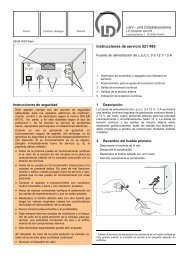
Fig. 9 Laue diagram at NaCl,<br />
U = 35 kV, I = 1 mA, L = 15 mm, �t = 1800 s<br />
(for identifying the reflections refer to Table 1)<br />
b) Laue diagram at LiF:<br />
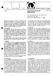
Fig. 10 Laue diagram at LiF,<br />
U = 35 kV, I = 1 mA, L = 11 mm, �t = 1200 s<br />
(for identifying the reflections refer to Table 3)<br />
Evaluation<br />
– Lay a piece of millimetre-square graph paper on the X-ray<br />
film, read the x Q- and y Q-co-ordinates of the reflections,<br />
and calculate the z Q-co-ordinate according to Eq. (XIII).<br />
– Identify the indices h, k and l according to Eq. (XIV).<br />
– Calculate the spacing of the lattice planes d according to<br />
Eq. (VI), the Bragg angle � according to Eq. (XV) and the<br />
wavelength � according to Eq. (V).<br />
– Now apply Eqs. (XI) and (XIV) to calculate the co-ordinates<br />
x P and y P or x Q and y Q, respectively, and compare them<br />
with the measured values.<br />
5<br />
a) Laue diagram at NaCl:<br />
Tab. 1: Coordinates and extended Miller indices of the reflections<br />
in the Laue diagram of NaCl (*: calculated)<br />
x Q<br />
mm<br />
yQ<br />
mm<br />
zQ<br />
* h k l<br />
mm<br />
x<br />
mm *<br />
y<br />
mm *<br />
1 17.2 8.4 9,3 4 2 2 15.0 7.5<br />
−7.8 −15.2 7,7 −2 −4 2 −7.5 −15.0<br />
7.8 −15.2 7,7 2 −4 2 7.5 −15.0<br />
15.8 −8.0 8,2 4 −2 2 15.0 −7.5<br />
2 12.6 −0.4 4,6 6 0 2 11.2 0.0<br />
0.2 14.5 5,9 0 6 2 0.0 11.2<br />
−13.2 −0.1 5,0 −6 0 2 −11.2 0.0<br />
0.0 −11.2 3,7 0 −6 2 0.0 −11.2<br />
3 11.5 3.6 4,2 6 2 2 10.0 3.3<br />
4.2 12.4 4,9 2 6 2 3.3 10.0<br />
−4.3 13.0 5,3 −2 6 2 −3.3 10.0<br />
−12.2 4.0 4,7 −6 2 2 −10.0 3.3<br />
−11.2 −3.9 4,1 −6 −2 2 −10.0 −3.3<br />
−3.3 −10.2 3,4 −2 −6 2 −3.3 −10.0<br />
3.2 −10.0 3,3 2 −6 2 3.3 −10.0<br />
10.5 −3.9 3,7 6 −2 2 10.0 −3.3<br />
4 9.0 9.2 4,8 4 4 2 8.6 8.6<br />
−11.0 11.0 6,6 −4 4 2 −8.6 8.6<br />
−9.0 −9.2 4,8 −4 −4 2 −8.6 −8.6<br />
9.0 −9.0 4,7 4 −4 2 8.6 −8.6<br />
5 9.0 5.8 3.4 6 4 2 7.5 5.0<br />
6.3 9.2 3.7 4 6 2 5.0 7.5<br />
−6.5 9.8 4.1 −4 6 2 −5.0 7.5<br />
−9.5 6.2 3.8 −6 4 2 −7.5 5.0<br />
−8.2 −5.5 3.0 −6 −4 2 −7.5 −5.0<br />
−5.2 −8.0 2.8 −4 −6 2 −5.0 −7.5<br />
6 6.4 6.2 2.4 3 3 1 5.3 5.3<br />
−6.8 6.8 2.8 −3 3 1 −5.3 5.3<br />
−5.8 −5.8 2.1 −3 −3 1 −5.3 −5.3<br />
5.3 −5.3 1.8 3 −3 1 5.3 −5.3<br />
7 6.8 1.3 1.5 5 1 1 6.0 1.2<br />
1.8 7.8 2.0 1 5 1 1.2 6.0<br />
−1.2 8.0 2.0 −1 5 1 −1.2 6.0<br />
−7.2 1.2 1.7 −5 1 1 −6.0 1.2<br />
−7.0 −1.5 1.6 −5 −1 1 −6.0 −1.2<br />
Tab. 2: Spacing of lattice planes d, Bragg angle � and<br />
wavelength � associated with the sets of lattice planes of NaCl,<br />
a 0 = 564.02 pm [1]<br />
h k l<br />
d<br />
pm<br />
�<br />
�<br />
pm<br />
4 2 2 115.1 24.1� 94.0<br />
6 0 2 89.2 18.4� 56.3<br />
6 2 2 85.0 17.5� 51.1<br />
4 4 2 94.0 19.5� 62.8<br />
6 4 2 75.4 15.5� 40.3<br />
3 3 1 129.4 13.3� 59.5<br />
5 1 1 108.5 11.1� 41.8
<strong>P7.1.2.2</strong> <strong>LD</strong> Physics Leaflets<br />
b) Laue diagram at LiF:<br />
Tab. 3: Co-ordinates and extended Miller indices of the reflections<br />
in the Laue diagram of LiF (*: calculated)<br />
x Q<br />
mm<br />
yQ<br />
mm<br />
zQ<br />
* h k l<br />
mm<br />
x<br />
mm *<br />
y<br />
mm *<br />
1 14.2 −0.1 7.0 4 0 2 14.7 0.0<br />
0.2 13.3 6.3 0 4 2 00 14.7<br />
−14.2 0.0 7.0 −4 0 2 −14.7 0.0<br />
0.1 −15.2 7.8 0 −4 2 0.0 −14.7<br />
2 10.5 5.0 5.0 4 2 2 11.0 5.5<br />
5.5 10.0 4.9 2 4 2 5.5 11.0<br />
−5.8 10.3 5.2 −2 4 2 −5.5 11.0<br />
−10.5 5.2 5.1 −4 2 2 −11.0 5.5<br />
−11.0 −5.8 5.6 −4 −2 2 −11.0 −5.5<br />
−5.6 −11.5 5.9 −2 −4 2 −5.5 −11.0<br />
5.8 −11.2 5.7 2 −4 2 5.5 −11.0<br />
11.0 −5.5 5.5 4 −2 2 11.0 −5.5<br />
3 8.0 0.0 2.6 6 0 2 8.3 0.0<br />
−0.5 7.2 2.2 0 6 2 0.0 8.3<br />
−9.1 −0.3 3.3 −6 0 2 −8.3 0.0<br />
0.5 −8.0 2.6 0 −6 2 0.0 −8.3<br />
4 7.2 2.0 2.3 6 2 2 7.3 2.4<br />
2.2 6.5 2.0 2 6 2 2.4 7.3<br />
−2.0 7.4 2.4 −2 6 2 −2.4 7.3<br />
−7.0 2.2 2.2 −6 2 2 −7.3 2.4<br />
−7.2 −2.3 2.4 6 −2 2 −7.3 −2.4<br />
−2.2 −7.8 2.7 2 −6 2 −2.4 −7.3<br />
2.7 −7.6 2.6 2 −6 2 2.4 −7.3<br />
7.2 −2.8 2.4 6 −2 2 7.3 −2.4<br />
5 6.0 5.8 2.8 4 4 2 6.3 6.3<br />
−6.0 6.0 2.9 −4 4 2 −6.3 6.3<br />
−6.2 −6.3 3.1 −4 −4 2 −6.3 −6.3<br />
6.5 −6.5 3.3 4 −4 2 6.3 −6.3<br />
6 4.0 3.5 1.2 3 3 1 3.9 3.9<br />
−3.5 3.6 1.1 −3 3 1 −3.9 3.9<br />
−3.8 −4.0 1.3 −3 −3 1 −3.9 −3.9<br />
4.2 −4.0 1.4 3 −3 1 3.9 −3.9<br />
Tab. 4: Spacing of lattice planes d, Bragg angle � and<br />
wavelength � associated with the sets of lattice planes of LiF,<br />
a 0 = 402.80 pm [1]<br />
h k l<br />
Results<br />
A Laue diagram is a diffraction photograph of a monocrystal<br />
taken with a continuous (“white”) spectrum of X-rays. From the<br />
continuum of the X-rays only those wavelengths (cf. Tables 2<br />
and 4) contribute to the diffraction pattern taken on a plane film<br />
which fulfil the Bragg condition for a particular set of lattice<br />
planes.<br />
The symmetry of the Laue diagrams is in accordance with the<br />
cubic structure of the NaCl and the LiF crystal.<br />
Literature<br />
d<br />
pm<br />
[1]Handbook of Chemistry and Physics, 52nd Edition (1971−<br />
72), The Chemical Rubber Company, Cleveland, Ohio, USA.<br />
�<br />
�<br />
pm<br />
4 0 2 90.1 26.6� 80.6<br />
4 2 2 82.2 24.1� 67.1<br />
6 0 2 63.7 18.4� 40.3<br />
6 2 2 60.7 17.5� 36.5<br />
4 4 2 67.1 19.5� 44.8<br />
3 3 1 92.4 13.3� 42.5<br />
<strong>LD</strong> <strong>DIDACTIC</strong> GmbH ⋅ Leyboldstrasse 1 ⋅ D-50354 Hürth ⋅ Phone (02233) 604-0 ⋅ Telefax (02233) 604-222 ⋅ E-mail: info@ld-didactic.de<br />
© by <strong>LD</strong> <strong>DIDACTIC</strong> GmbH Printed in the Federal Republic of Germany<br />
Technical alterations reserved
<strong>LD</strong> Physics Leaflets <strong>P7.1.2.2</strong><br />
Addendum 1:<br />
The larger film 554 896 enables the recording of larger images, which provide more<br />
resolution, but also require a bit more exposure time.<br />
Hint: To reduce the black area in the middle, caused by the direct beam, glue a 3x3 mm piece<br />
of the lead foil from an already opened film sheet in front of the film during exposure.<br />
Addendum 2:<br />
The crystals 554 87 and 554 88 are usually delivered on a glass plate 25 x 25 x 1 mm. This<br />
plate is glass, not the crystal.