Line coupler 729 765 - LD DIDACTIC
Line coupler 729 765 - LD DIDACTIC
Line coupler 729 765 - LD DIDACTIC

You also want an ePaper? Increase the reach of your titles
YUMPU automatically turns print PDFs into web optimized ePapers that Google loves.
Instruction sheet<br />
<strong>Line</strong> <strong>coupler</strong> <strong>729</strong> <strong>765</strong><br />
Carefully read the instruction sheet before putting the device into operation!<br />
Prescribed use<br />
1<br />
Ha 12/97<br />
The training panel is part of the modular training panel system TPS and is designed to ensure<br />
the electrical isolation between two EIB lines (European Installation Bus).<br />
Using the ETS (EIB Tool Software) the EIB experment setups are configured and put into operation.<br />
Location of use<br />
• Operation in dry rooms, which are suitable for experimenting with electrical equipment or installations.<br />
• Operation exclusively in panel frames.<br />
1. Safety instructions<br />
The training panel is designed to comply with safety class I and corresponds to the safety stipulations<br />
set forth under EN 61010.<br />
When the device is operated as directed, safe operation is guaranteed. However, safety cannot<br />
be guaranteed if the device is operated improperly or handled without the appropriate care.<br />
• Only use safety connecting leads/bridging plugs because the voltage at the connection sokkets<br />
“L1” and “N” are contact-hazardous!<br />
• Establish the protective conductor/PE connection.<br />
• Only carry out modifications to the experiment set up when the power is off.<br />
• If you assume that safe operation is no longer possible (e.g. in the case of visible damage),<br />
then the device must be switched off immediately and secured to prevent it from being accidentally<br />
put back into operation.
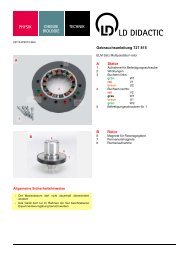
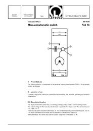
2. Description<br />
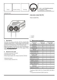
1 Connection socket “L1”, for the mains power supply/experiment setup connection.<br />
2 Connection socket “N”, for the mains power supply/experiment setup connection.<br />
3 Main line “+”, EIB system voltage 29 V DC<br />
4 Main line “–”, EIB system voltage 0 V DC<br />
5 LED “<strong>Line</strong>” indicates that a data telegram is on the line.<br />
6 Operating status indicator “ON”<br />
7 LED “Main line” indicates that a data telegram is on the main line.<br />
8 Connection socket “PE”, is not required for this training panel<br />
9 <strong>Line</strong> “+”, EIB system voltage 29 V DC<br />
bl<strong>Line</strong> “–”, EIB system voltage 0 V DC<br />
bmLED/Programming button for the allocation of the physical address, only in conjunction with<br />
the ETS software.<br />
3. Functions<br />
1<br />
2<br />
3<br />
4<br />
5<br />
6<br />
7<br />
8<br />
Alternatively the line <strong>coupler</strong> can be used as a range <strong>coupler</strong> or line amplifier.<br />
Data telegrams can be suppressed using a programmable address filter table located between<br />
the lines.<br />
4. ETS product information<br />
Manfacturer: ABB<br />
Product family: System components<br />
Product type: <strong>Line</strong> couple<br />
Catalog entry: LK/S 1<br />
Medium type: Twisted pair<br />
5. Technical data<br />
Design: ABB i-bus EIB line <strong>coupler</strong>, modular<br />
EIB system voltage: 29 V DC via the EIB<br />
Connections: 4-mm safety sockets<br />
2<br />
9<br />
bl<br />
bm