P3.7.2.2 - LD DIDACTIC
P3.7.2.2 - LD DIDACTIC
P3.7.2.2 - LD DIDACTIC

Create successful ePaper yourself
Turn your PDF publications into a flip-book with our unique Google optimized e-Paper software.
0908-Sel/Wit<br />
Electricity<br />
Electromagnetic oscillations and waves<br />
Decimeter-range waves<br />
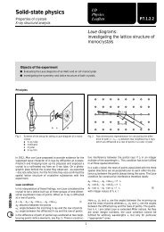
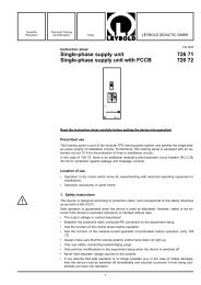
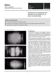
Fig. 1 Experimental setup for the transmission of audio signals<br />
with the UHF transmitter<br />
<strong>LD</strong><br />
Physics<br />
Leaflets<br />
Amplitude modulation<br />
of decimeter waves<br />
Objects of the experiments<br />
Assembling a transmission line for the transmission of audio signals with the UHF transmitter.<br />
1<br />
Principles<br />
By means of the UHF transmitter, audio signals in the<br />
frequency range from 100 Hz to 10 kHz can be transmitted by<br />
amplitude modulation of the signal<br />
E(t) = E 0 ⋅ cos(2� ⋅ � 0 ⋅ t) (I)<br />
� 0 = 433.92 MHz: transmitting frequency<br />
emitted by the UHF transmitter with the audio signal u(t). The<br />
modulated signal then has the form<br />
E AM(t) = E 0 ⋅ (1 + k AM ⋅ u(t)) ⋅ cos(2� ⋅ � 0 ⋅ t) (II)<br />
k AM: coefficient of coupling<br />
A receiver dipole with a high-frequency rectifier serves as a<br />
receiver which filters the high-frequency part out, while letting<br />
only the low-frequency audio signal through. The audio signal<br />
is amplified and supplied to a broad-band speaker.<br />
Setup<br />
The experimental setup is illustrated in Fig. 1.<br />
<strong>P3.7.2.2</strong><br />
– Clamp the UHF transmitter in the saddle base and connect<br />
the loop dipole to the antenna output of the UHF transmitter.<br />
– Clamp the mounting rod for receiver dipoles in a saddle<br />
base, screw the receiver dipole with the diode on, and place<br />
it at a distance of about 1 m from the UHF transmitter.<br />
– Align the receiver dipole parallel to the loop dipole.<br />
– Use the screened cable BNC/4 mm to connect the modulation<br />
input of the UHF transmitter to the output of the<br />
function generator P.
<strong>P3.7.2.2</strong> <strong>LD</strong> Physics Leaflets<br />
Apparatus<br />
1 UHF transmitter . . . . . . . . . . . . . . 587 55<br />
1 plug-in unit 230 V AC / 12 V AC . . . . . 562 791<br />
1 function generator P, 100 MHz – 100 kHz 52256<br />
1 AC/DC-amplifier, 30 W . . . . . . . . . . 52261<br />
1 broad-band speaker . . . . . . . . . . . 58708<br />
3 saddle bases . . . . . . . . . . . . . . . 30011<br />
1 screened cable BNC/4 mm . . . . . . . . 57524<br />
4 connection leads, 100 cm . . . . . z.B. 50133<br />
Safety notes<br />
The UHF transmitter may not always conform to the limit<br />
values of class A (Group 2 of standard EN 55011). It may<br />
cause interference in other devices in the experimental<br />
room of a school or educational institution. Moreover,<br />
radio interference can occur up to a distance of several<br />
hundred meters. It is the responsibility of the user to take<br />
all precautions to ensure that devices installed outside of<br />
the experiment room can continue to work properly.<br />
Observe the notes in the instruction sheet of the UHF<br />
transmitter.<br />
Do not operate the transmitter longer than is necessary<br />
to conduct the experiment. Deactivate the transmitter<br />
immediately when the experiment is finished by<br />
switching off the plug-in supply unit.<br />
– Switch the function generator P on.<br />
function: sine<br />
coarse attenuator: × 0.1<br />
regulator DC: left stop<br />
– Connect the input of the AC/DC-amplifier to the receiver<br />
dipole and the output of the AC/DC-amplifier to the broadband<br />
speaker with twisted connection leads.<br />
– Switch the AC/DC-amplifier on.<br />
mode: AC<br />
amplification: × 10<br />
Offset compensation at the AC/DC-amplifier:<br />
– Set the regulator AC of the function generator and the<br />
continuous attenuator of the AC/DC-amplifier to the left<br />
stop, and adjust the offset potentiometer so that the green<br />
LED lights up.<br />
Carrying out the experiment<br />
– Put the UHF transmitter into operation by plugging in the<br />
plug-in unit, and choose the AM mode.<br />
– Set the regulator for the AC amplitude of the function<br />
generator P to the right stop (max.).<br />
– Turn the continuous attenuator of the AC/DC-amplifier to<br />
the right until the speaker can be well heard.<br />
– Vary the frequency at the function generator P between<br />
100 Hz and 10 kHz.<br />
– Vary the distance between the UHF transmitter and the<br />
receiver dipole with diode; get a barrier into the transmission<br />
line (e.g. a metal plate).<br />
Evaluation<br />
When the frequency of the function generator P is varied, the<br />
pitch of the speaker signal changes correspondingly.<br />
When the distance between the UHF transmitter and the<br />
receiver dipole is changed, the volume of the speaker signal<br />
varies.<br />
A barrier between the UHF transmitter and the receiver dipole<br />
reduces or even interrupts the transmission. However, a total<br />
interruption is often hindered due to reflection of the transmitted<br />
signal off nearby objects. The connection leads which<br />
conduct the signal from the receiver dipole to the amplifier can<br />
also, depending on their alignment, influence the received<br />
strength.<br />
Results<br />
Audio signals in the frequency range from 100 Hz to 10 kHz<br />
can be transmitted to a receiver by means of a UHF transmitter.<br />
After demodulation of the amplitude modulated signal of the<br />
UHF transmitter and its amplification, the audio signal can then<br />
be made audible with a speaker.<br />
<strong>LD</strong> <strong>DIDACTIC</strong> GmbH ⋅ Leyboldstrasse 1 ⋅ D-50354 Hürth ⋅ Phone (02233) 604-0 ⋅ Telefax (02233) 604-222 ⋅ E-mail: info@ld-didactic.de<br />
© by <strong>LD</strong> <strong>DIDACTIC</strong> GmbH Printed in the Federal Republic of Germany<br />
Technical alterations reserved