The Locomotive - Lighthouse Survival Blog
The Locomotive - Lighthouse Survival Blog
The Locomotive - Lighthouse Survival Blog

You also want an ePaper? Increase the reach of your titles
YUMPU automatically turns print PDFs into web optimized ePapers that Google loves.
1893.1 THE LOCOMOTIVE 136<br />
lino. 'I'lie total steam- pressure to be resisted would therefore be a little larger than we<br />
have assumed, aud the factor of safety would be correspondingly smaller. On the other<br />
hand, we have taken no account of the stiffening action of the flange of the head; and<br />
as there can be no d()ul)t that this flange stays the head sufliciently for a distance of at<br />
least three inches from the shell, perhaps we could fairly say that theunflared tubes have<br />
a factor of safety of 4, and the flared ones a factor of 15, notwithstanding the one row<br />
that projects above the center, line of the boiler. As a general rule, we consider 5 to be<br />
tiie proper factor of safety for boilers, except in braces and flat heads; the exception<br />
being made in the ca.se of braces partly because of the uncertain quality of iron that is<br />
used for them, and in the case of flat heads, on account of the general nebulosity sur-<br />
rounding all the formuhv yet proposed for calculating their strength. Hence we should<br />
not be inclined to recommend the use of plain, unflared tubes in a 66-inch boiler<br />
that is to carry 100 pounds pres-<br />
sure, especially when such an<br />
enormous gain in strength may<br />
be had by a little extra work.<br />
Moreover, all the foregoing calcu-<br />
lation has been based upon the<br />
assumption, which, as indicated<br />
above, is too often erroneous, that<br />
the tuhe-rollw(j has heen icell done.<br />
It is far better to use the flared<br />
tubes; and when these are used,<br />
there is not the least chance for<br />
doubt about the sufficiency of their<br />
holding power. We come, now,<br />
to the consideration of that part<br />
of the boiler-head which lies above<br />
the tubes. <strong>The</strong> tubes, it has been<br />
shown, possess sufficient holding<br />
power to amply stay the part of<br />
the head to which they are at-<br />
tached, and we may safely consider<br />
that they will also possess suffi-<br />
cient staying power to take care<br />
of the heads for, say, two inches<br />
'<br />
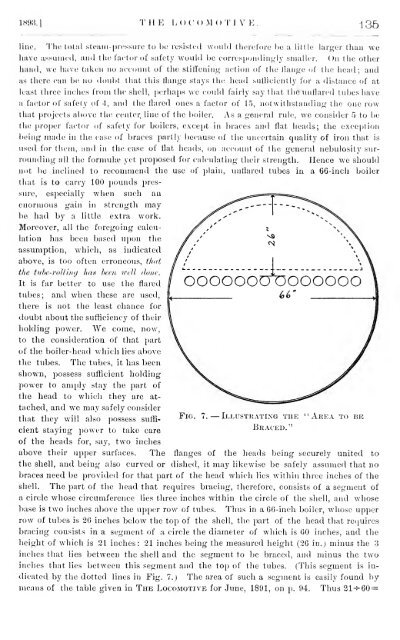
Fig. 7. — Illustrating the ' Area<br />
Braced."<br />
to be<br />
above their upper surfaces. <strong>The</strong> flanges of the heads being securely united to<br />
the shell, and being also curved or dished, it may likewise be safely assumed that no<br />
braces need be provided for that part of the head which lies within three inches of the<br />
shell. <strong>The</strong> part of the head that requires bracing, therefore, consists of a segment of<br />
a circle whose circumference lies three inches within the circle of the shell, and whose<br />
base is two inches above the upper row of tubes. Thus in a 66-inch boiler, whose upper<br />
row of tubes is 26 inches below the top of the shell, the part of the head that recjuires<br />
bracing consists in a segment of a circle the diameter of which is 60 inches, and the<br />
height of which is 21 inches: 21 inches being the measured height (26 in.) minus the 3<br />
inches that lies between the shell and the segment to be braced, and minus the two<br />
inches that lies between this segment and the top of the tubes. (This segment is indicated<br />
by the dotted lines in Fig. 7.) <strong>The</strong> area of such a segment is easily found by<br />
means of the table given in <strong>The</strong> <strong>Locomotive</strong> for June, 1891, on p. 94. Thus 21^60 =