WT-Prospekt engl NEU (Page 2) - Berriola
WT-Prospekt engl NEU (Page 2) - Berriola
WT-Prospekt engl NEU (Page 2) - Berriola

Create successful ePaper yourself
Turn your PDF publications into a flip-book with our unique Google optimized e-Paper software.
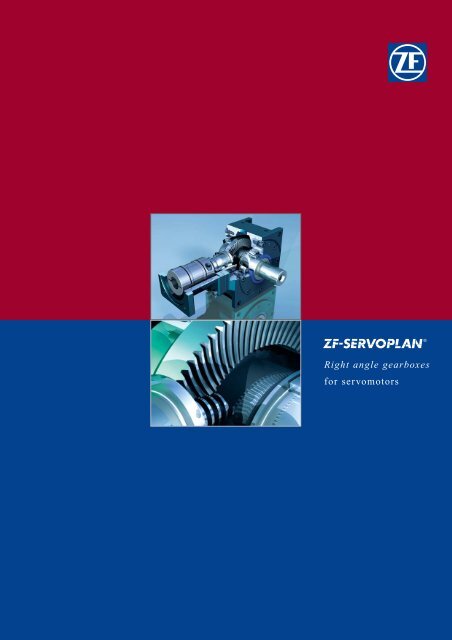
Right angle gearboxes<br />
for servomotors
2<br />
ZF-Duoplan 2K<br />
Two-speed Gearboxes<br />
ZF-Tiratron<br />
Hysteresis Brakes<br />
ZF-Ecolift<br />
Elevator Gearboxes<br />
Customer specific<br />
Gearboxes<br />
ZF-Servoplan PGE<br />
Servogearboxes Economy<br />
ZF-Servoplan PG<br />
Servogearboxes
ZF-Servoplan <strong>WT</strong><br />
Right Angle gearboxes<br />
Precision in movement<br />
The ZF Maschinenantriebe GmbH is able to<br />
offer you a wide range of machine drives,<br />
brakes and clutches for applications in<br />
engineering as well as customer specific<br />
drive solutions.<br />
Our development and production activities are<br />
focused on servo-assisted drives for automation<br />
engineering, two-speed drive gearboxes<br />
for machine tools as well as customer-specific<br />
drives, such as for printing machines,<br />
robot applications and elevator gearboxes.<br />
Our innovative standard products range from<br />
low backlash servogearboxes (ZF-Servoplan),<br />
and robust two-speed gearboxes (ZF-<br />
Duoplan) to hysteresis clutches and brakes<br />
for non-contact web control (ZF-Tiratron).<br />
3
4<br />
Right angle gearboxes<br />
The ZF Servoplan bevel gear system of the <strong>WT</strong> range has been designed for highly dynamic servodrives.<br />
The newly developed hypoid gearing allows for high transmission ratios. A reduced torsional backlash and a high<br />
position accuracy are achieved through optimized manufacturing techniques. These features make these transmission<br />
ranges most suitable for applications in automation engineering.<br />
Apart from right angle<br />
gears for servodrives,<br />
ZF Maschinenantriebe<br />
GmbH also offers planetary<br />
gearboxes with a low<br />
backlash suitable for<br />
automation engineering.
1. Newly designed Gleason hypoid gearing for the most exact regulating accuracy which allows the high<br />
transmission ratios of a bevel gear<br />
2. Reduced backlash as a result of optimized manufacturing techniques<br />
3. Maintenance-free thanks to life-time lubrication<br />
4. The high-quality tapered roller bearings ensure a good tilt resistance and ideal bearing loads<br />
5. Backlash-free torque transmission as a result of a frictional connection between shaft and hub<br />
6. One-piece low-weight cast aluminum casing for highest stiffness<br />
7. Optimized contact pattern of the hypoid gearing for even tooth loads<br />
8. Highest possible efficiency of up to 96 %<br />
5<br />
3<br />
1<br />
8<br />
2<br />
7<br />
4<br />
6<br />
5
6<br />
Right angle gearboxes<br />
T echnical data:<br />
Nominal<br />
output torque<br />
Emergency stop torque 1)<br />
Max. acceleration<br />
torque<br />
Max. input speed<br />
Nominal<br />
input speed<br />
Backlash<br />
Torsional rigidity<br />
Moments of intertia<br />
Max. axial force<br />
Max. radial force 2)<br />
Idling torque<br />
(n1 = 3000 rpm)<br />
Lifetime 3)<br />
Efficiency<br />
Weight<br />
Operating noise at<br />
n an = 3000 rpm<br />
1) Max.1000 times in gearboxes lifetime.<br />
2) At a maximum of 1000 cycles per hour, with the<br />
correction factor to be taken into consdideration<br />
in any other case.<br />
3) Collective load as a basis for the design.<br />
4) Resultant force: center of<br />
output shaft at ouput speed 400 rpm.<br />
Lubrication<br />
Surface protection<br />
Installation position<br />
Operating temperature<br />
Direction of rotation input to output<br />
Type of protection<br />
Dimensions(mm):<br />
i<br />
Size:<br />
<strong>WT</strong><br />
35<br />
T 2N (Nm) 3-10 35 70 140 260 720 1 440<br />
12-15 25 50 95 180 510 1 020<br />
T 2Not (Nm) 3-10 70 140 280 520 1 440 2 880<br />
12-15 50 100 190 360 1 020 2 040<br />
T 2B (Nm) 3-10 53 105 210 390 1 080 2 160<br />
12-15 38 75 143 270 765 1 530<br />
n 1max (rpm) 8 000 8 000 7 000 6 000 5 000 4 500<br />
n 1 n (rpm) 6 000 6 000 5 000 4 000 3 000 2 500<br />
(arcmin) Stand. ≤ 5 ≤ 5 ≤ 4 ≤ 4 ≤ 4 ≤ 4<br />
redu . -1 ≤ 3 ≤ 3 ≤ 2 ≤ 2 ≤ 2 ≤ 2<br />
C 1 (Nm/ 3.5 7 17.5 39 103 210<br />
arcmin)<br />
l 1 (kg cm 2 ) 3 0.43 1.10 2.5 6.7 24 72<br />
4 0.31 0.77 1.8 4.7 16 48<br />
5 0.24 0.63 1.4 3.8 13 37<br />
6 0.22 0.56 1.3 3.4 11 28<br />
8 0.18 0.47 1.1 2.8 8.6 24<br />
10 0.16 0.43 1.0 2.5 7.5 20<br />
12 0.15 0.41 0.93 2.4 6.9 18<br />
15 0.14 0.39 0.89 2.3 6.3 16<br />
F A (N) 1 650 2 450 3 600 5 000 7 500 11 250<br />
F R (N) 3 300 4 900 7 200 10 000 15 000 22 500<br />
T 01 (Nm) 3 0.044 0.079 0.114 0.190 0.390 0.729<br />
10 0.024 0.043 0.065 0.101 0.189 0.311<br />
L h (h) > 30 000 > 30 000 > 30 000 > 30 000 > 30 000 > 30 000<br />
3-10 ≥ 96% ≥ 96% ≥ 96% ≥ 96% ≥ 96% ≥ 96%<br />
12/15 ≥ 93% ≥ 93% ≥ 93% ≥ 93% ≥ 93% ≥ 93%<br />
m (kg) 2.5 5 8.5 15 28 48<br />
L p (db(A)) ≤ 66 ≤ 66 ≤ 68 ≤ 68 ≤ 70 ≤ 72<br />
Lifetime lubrication, closed system<br />
Prime coat RAL 9005 - dull black<br />
any<br />
- 10 0 C to 100 0 C<br />
same as motor<br />
IP 64<br />
<strong>WT</strong><br />
35<br />
<strong>WT</strong><br />
70<br />
<strong>WT</strong><br />
70<br />
<strong>WT</strong><br />
140<br />
<strong>WT</strong><br />
140<br />
<strong>WT</strong><br />
260<br />
<strong>WT</strong><br />
260<br />
<strong>WT</strong><br />
700<br />
<strong>WT</strong><br />
700<br />
<strong>WT</strong><br />
1400<br />
<strong>WT</strong><br />
1400<br />
A 60 80 100 120 146 196<br />
B 90 115 140 170 215 260<br />
b(g6) 89 105 125 150 195 245<br />
g 13.5 8.5 8 8 10 10<br />
o 9 14 18 23 32 42<br />
p1 39 49 59 72 91 112<br />
p2 22 27 33 40 52 70<br />
k1 6.6 9 11 14 17.5 17.5<br />
k2 M6 M8 M10 M12 M16 M16<br />
q 8 10 11 13 15 17<br />
d2 (k6) 20 24 32 40 55 70<br />
l2 35 40 50 60 90 110<br />
f2 80 90 110 130 175 220<br />
n 1.5 1.5 2 2 2 2<br />
dw (H7) 20 25 30 40 55 70<br />
ds (f7) 24 30 36 50 68 80<br />
h0 20 22 26 29 32 34<br />
h1 23 25 29 33 37 40<br />
fs 71.5 79.5 93 107 127 159<br />
d1 9/11/14 11/14/19 14/19/24 19/24/32 24/32/38 32/38/48<br />
l1 23/26/30 26/30/40 30/40/50 40/50/60 50/60/80 60/80/80<br />
u x f1 55 x 130 75 x 168 90 x 191 115 x 220 140 x 260 190 x 335<br />
- 90 x 168 115 x 191 140 x 220 190 x 265 260 x 345<br />
75 x 140 90 x 180 115 x 201 140 x 235 190 x 280 -<br />
r According to DIN 332 Form D,<br />
v PCD, spigot dia thread and centering depth<br />
w<br />
s<br />
m<br />
according to respective motor data sheets.
Installation dimensions<br />
d2<br />
r<br />
Side 1<br />
b<br />
v<br />
dw<br />
s<br />
g<br />
n<br />
12<br />
l1<br />
d1<br />
f2<br />
A<br />
p2 p2<br />
w<br />
u<br />
Design 1L<br />
Design 1LSV<br />
hs<br />
g<br />
k2<br />
p 2<br />
p 2<br />
q<br />
m+0.5<br />
b<br />
*<br />
h 1<br />
h 0<br />
dw<br />
B<br />
Side 4<br />
Side 2 Side 5<br />
ds<br />
p1<br />
p1<br />
Side 3<br />
p1<br />
*<br />
B<br />
p1<br />
f1<br />
Design 3L<br />
k1<br />
Design 3LSV<br />
Side A<br />
*Hollow shaft. Optional fixing via shrink ring<br />
7
8<br />
Technical explanations<br />
Shape of output shaft<br />
Bevel gear systems with following<br />
output shaft types:<br />
Type 1L<br />
Solid shaft, no keyway;<br />
Lefthand output, seen from input.<br />
Type 3L<br />
Solid shaft, no keyway;<br />
Righthand output, seen from input.<br />
All solid shaft types have a faceend<br />
centering bore with D DIN 332<br />
thread.<br />
Type 1LSV<br />
Hollow shaft. Optional fixing via<br />
shrink ring.<br />
Lefthand output, seen from input.<br />
Type 3LSV<br />
Hollow shaft. Optional fixing via<br />
shrink ring. Righthand output, seen<br />
from input.<br />
IM B5 IM V1 IM V3<br />
Installation position<br />
The right angle gearboxes are of B5<br />
design for flange mounting.<br />
Installation position as required.<br />
As per DIN EN 60 034-7 (06.96 issue),<br />
the installation positions illustrated can<br />
be used.
Configuration and selection<br />
Type of protection<br />
Right angle gearboxes are protected<br />
against penetration of diverse external<br />
media. The type of protection is<br />
designated as IEC 35-5 for electric<br />
machinery and specified by the letters<br />
IP (international protection) and two<br />
code numbers.<br />
For mechanical right angle gears the<br />
designation is IP64.<br />
The first digit designates the degree of<br />
protection against contact (screen protection)<br />
and penetration of foreign<br />
bodies.<br />
Operating modes S4 and S5<br />
The right angle gearboxes are<br />
designed for operating mode<br />
S4 (intermittent periodic duty<br />
with starting) and operating<br />
mode S5 (intermittent periodic<br />
duty with braking), both as per<br />
EN 60034-1.<br />
In this instance, the cyclic<br />
duration factor (c.d.f) should<br />
not exceed 60%. For S4 mode<br />
(intermittent periodic duty),<br />
the following applies:<br />
tA + tB c.d.f. = ––––––x 100%<br />
tS For S5 mode (intermittent<br />
periodic duty with braking),<br />
the following applies:<br />
tA + tB + tBr c.d.f. = –––––––––––x t 100%<br />
S<br />
One process sequence tS comprises<br />
one each of rise time, load<br />
period, braking time (if needed)<br />
and idle time. This is defined as<br />
a cycle.<br />
v; n ;P v<br />
In this instance, the digit 6 means<br />
– protection against dust infiltration<br />
(dust-tight)<br />
– complete screen protection.<br />
The second digit designates the<br />
degree of protection against water.<br />
In this instance, the digit 4 means<br />
– water sprayed against the machine<br />
from all directions (jet water)<br />
must not cause any damage to<br />
the machine.<br />
tA tB tA tB tBr tS<br />
tS<br />
Reduction factor k<br />
1,0<br />
0,8<br />
0,6<br />
0,4<br />
0,2<br />
0,0<br />
0 1000 2000 3000 4000 5000<br />
Number of cycles (1/h)<br />
The number of cycles should not<br />
exceed 1000 per hour.<br />
If more than 1000 cycles per hour<br />
are required, this is possible with<br />
reduced input torque T2B perm.<br />
(Reduction factor k)<br />
n: speed<br />
v: velocity (speed)<br />
Pv : power loss<br />
t: time<br />
tA: rise time<br />
tB: load time<br />
tBr: braking time<br />
ts: cycle duration<br />
t<br />
9
10<br />
Gearbox selection<br />
The following is intended as an aid for simple and fast selection of a gearbox for your use in consideration of the mode<br />
of operation. C.d.f. = cyclic duration factor. S.o.t. = switch-on time. Indices: Capital letters = physical gearbox limit values<br />
(nominal value). Small letters = actually applied values (actual value).<br />
Continuous operation<br />
Determination of nom.<br />
load torque on gearbox<br />
output T 2N<br />
T 2 < T 2N<br />
yes<br />
Choose smaller ratio<br />
or larger motor<br />
Choose<br />
larger gearbox<br />
yes<br />
no<br />
no<br />
no<br />
Determination of switch-on time<br />
c.d.f. > 60%<br />
or<br />
s.o.t. > 20 min<br />
Choose<br />
larger gearbox<br />
Determination of gearbox ratio<br />
n 1n < n 1N<br />
yes<br />
Determ. of emergency stop torque *<br />
T 2not < T 2NOT<br />
yes<br />
Determination of bearing load<br />
F r < F R<br />
F a < F A<br />
Choose<br />
larger gearbox<br />
Gearbox selection completed<br />
no<br />
no<br />
Cyclic operation<br />
Determination of no. of cycles<br />
Determ. of reduction factor k*<br />
Determ. of max. acceleration<br />
torque on gearbox output T 2b *<br />
T 2b < T 2B perm.<br />
yes<br />
* T 2Bperm. = T 2B • k<br />
T 2b = J app • ( ) + T Last<br />
* T 2not depending on application<br />
n t
Quotation?<br />
For fastest processing of your request we need following facts from you simply by:<br />
Fax: ++49/(0)40-535-40024 or<br />
E-Mail: marzahl@marzahl.de<br />
Motor make:<br />
Type:<br />
Connection dimensions:<br />
Shaft diameter (mm):<br />
Centering diameter (mm):<br />
Fixing hole circle diameter (mm):<br />
Thread size (pitch): M<br />
Power (kw):<br />
Gearbox size: <strong>WT</strong><br />
Gearbox ratio (i):<br />
Design:<br />
Basis of quotation (volume):<br />
Planned annual demand:<br />
Subject to technical change without notice. For installation investigation purposes,<br />
please request installation drawings; only the data contained therein is binding.<br />
Please check out our homepage: www.antriebstechniken.de<br />
11
inding.<br />
is therein contained data the only drawings; installation request please studies, For notice. without<br />
Marzahl Vertrieb GmbH<br />
change<br />
Ulzburger Straße 528<br />
D-22844 Norderstedt<br />
Phone: +49(0)40-535-4000<br />
technical<br />
Fax: +49(0)40-535-40024<br />
to<br />
e-Mail: marzahl@marzahl.de<br />
Internet: www.antriebstechniken.de Subject