Directed Energy - Navsea - The US Navy
Directed Energy - Navsea - The US Navy
Directed Energy - Navsea - The US Navy

You also want an ePaper? Increase the reach of your titles
YUMPU automatically turns print PDFs into web optimized ePapers that Google loves.
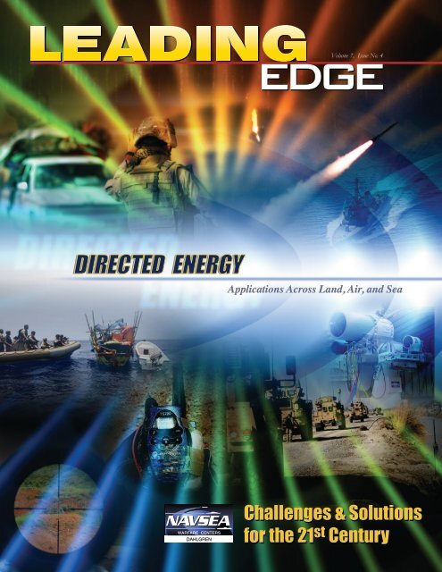
Volume 7, Issue No. 4<br />
Applications Across Land, Air, and Sea<br />
Challenges & Solutions<br />
for the 21st Challenges & Solutions<br />
for the 21 Century<br />
st Century
Table of Contents<br />
Volume 7, Issue No. 4<br />
<strong>Directed</strong> <strong>Energy</strong><br />
3 Leading Edge <strong>Directed</strong>-<strong>Energy</strong> RDT&E<br />
Captain Michael H. Smith<br />
4 <strong>Directed</strong>-<strong>Energy</strong> Topics in This Issue<br />
Mr. Dale Sisson<br />
Past, Present, and Future<br />
6 Naval <strong>Directed</strong>-<strong>Energy</strong> Weapons —<br />
No Longer a Future Weapon Concept<br />
David C. Stoudt<br />
12 Historical Overview of <strong>Directed</strong>-<strong>Energy</strong> Work at Dahlgren<br />
Stuart Moran<br />
26 History of Laser Weapon Research<br />
Melissa Olson<br />
36 Laser Weapon System (LaWS) Adjunct to the Close-In<br />
Weapon System (CIWS)<br />
Robin Staton and Robert Pawlak<br />
RDT&E, Acquisition, and Warfare Management<br />
44 <strong>The</strong> Acquisition Challenge Associated With <strong>Directed</strong>-<strong>Energy</strong> RDT&E<br />
Mike Kotzian<br />
Technology, Modeling, and Assessment<br />
50 <strong>The</strong> Basics of Electric Weapons and Pulsed-Power Technologies<br />
Stuart Moran<br />
58 Solid Modeling of <strong>Directed</strong>-<strong>Energy</strong> Systems<br />
Joseph F. Sharrow<br />
64 A Fundamental Key to Next-Generation <strong>Directed</strong>-<strong>Energy</strong> Systems<br />
<strong>Directed</strong> <strong>Energy</strong> Division, Electromagnetic and Sensor Systems Department<br />
70 Active Denial Array<br />
Randy Woods and Matthew Ketner<br />
74 <strong>Directed</strong> <strong>Energy</strong> in the Military Environment<br />
LT Leedjia Svec, Jeremy Beer, and Dave Freeman<br />
High-Power Microwave<br />
78 <strong>Directed</strong> <strong>Energy</strong> Using High-Power Microwave Technology<br />
Jacob Walker and Matthew McQuage<br />
High-<strong>Energy</strong> Laser<br />
82 Laser Counter Rocket, Artillery, and Mortar (C-RAM) Efforts<br />
Michael Libeau<br />
Nonlethal Capabilities<br />
86 Multifrequency Radio-Frequency (RF) Vehicle Stopper<br />
Stephen A. Merryman<br />
92 High-Power Electrical Vehicle-Stopping Systems<br />
Jordan Chaparro and Melanie Everton<br />
96 Nonlethal Small-Vessel Stopping With High-Power<br />
Microwave Technology<br />
Jacob Walker<br />
1
2<br />
Naval Surface Warfare Center, Dahlgren Division (NSWCDD)<br />
Captain Michael H. Smith, Commander<br />
Carl R. Siel, Jr., Technical Director<br />
David C. Stoudt, Distinguished Engineer for <strong>Directed</strong> <strong>Energy</strong> (ST) and<br />
NAVSEA Technical Warrant for <strong>Directed</strong> <strong>Energy</strong> and Electric Weapon Systems<br />
Janice Miller, Corporate Communications Director (Acting)<br />
Steve Zehring, Managing Editor<br />
Margie Stevens, Production Coordinator<br />
Patrice Waits, Editor & Layout<br />
Clement Bryant, Layout Design & Graphic Artist<br />
Kellie Yeatman, Graphic Artist<br />
Trey Hamlet, Graphic Artist/3-D Modeling<br />
Electromagnetic & Sensor Systems<br />
Dale Sisson, Head, Q Department<br />
Brandy Anderson, Graphic Artist/Cover Design<br />
NSWCDD<br />
Jordan Chaparro<br />
Melanie Everton<br />
Matthew Ketner<br />
Michael Libeau<br />
Matthew McQuage<br />
Stephen A. Merryman<br />
Stuart Moran<br />
Melissa Olson<br />
Robert Pawlak<br />
Joseph F. Sharrow<br />
Robin Staton<br />
Jacob Walker<br />
Randy Woods<br />
Defense Acquisition University<br />
Mike Kotzian<br />
Naval Medical Research Unit – San Antonio<br />
Jeremy Beer<br />
Dave Freeman<br />
LT Leedjia Svec<br />
<strong>The</strong> Leading Edge magazine is produced by the Naval Surface Warfare Center, Dahlgren,<br />
Virginia. <strong>The</strong> purpose of the publication is to showcase technical excellence across the Warfare<br />
Centers and promote a broader awareness of the breadth and depth of knowledge and support<br />
available to the <strong>Navy</strong> and DoD.<br />
Address all correspondence to Corporate Communications, C6<br />
Email: dlgr_nswc_c6@navy.mil; or write to<br />
Commander<br />
Naval Surface Warfare Center, Dahlgren Division<br />
Corporate Communications, C6<br />
6149 Welsh Road, Suite 239<br />
Dahlgren, VA 22448-5130<br />
NSWCDD/MP-09/34<br />
Approved for public release; distribution is unlimited.
Introduction<br />
Leading Edge <strong>Directed</strong>-<strong>Energy</strong> RDT&E<br />
Captain Michael H. Smith, <strong>US</strong>N<br />
Commander, NSWCDD<br />
Dahlgren first launched research and development efforts devoted<br />
to harnessing the power of electromagnetic energy over<br />
40 years ago. From early work with voltage multipliers and pulsepowered<br />
technology, to today’s high-energy lasers and high-power<br />
microwave technologies, the Naval Surface Warfare Center,<br />
Dahlgren Division (NSWCDD) has led, and continues to lead,<br />
cutting-edge directed-energy research, development, testing, and<br />
evaluation. Our commitment in this area only grows stronger—<br />
evidenced by our chartering of the <strong>Directed</strong> <strong>Energy</strong> Warfare Office<br />
(DEWO)—in order to provide increased focus on warfighting<br />
applications of these technologies.<br />
Today’s military forces face a wide array of challenges in diverse<br />
operating environments around the world. <strong>Directed</strong> energy<br />
offers unique and flexible options to address today’s challenges,<br />
as traditional kinetic weapons are often of limited value in peacekeeping<br />
missions and in urban environments, where restricted<br />
rules of engagement typify the norm. Kinetic weapons can also be<br />
more costly or ineffective to employ against asymmetric threats.<br />
<strong>The</strong> Chief of Naval Operations (CNO) recently placed added<br />
emphasis on directed energy and on expanding the range of directed-energy<br />
capabilities. In response, scientists and engineers at<br />
NSWCDD are actively developing prototype systems in a number<br />
of areas that you will read about in this issue—areas that have<br />
been successfully demonstrated and tested in our <strong>Navy</strong> laboratories<br />
and ranges.<br />
In this issue of <strong>The</strong> Leading Edge magazine, you will trace the<br />
rich history of directed-energy work at Dahlgren, gain insight into<br />
directed-energy weapons already fielded or being readied for the<br />
field, and learn about prototypes that show real promise for providing<br />
incredibly effective offensive and defensive directed-energy<br />
solutions. For example, scientists and engineers at NSWCDD<br />
are leading the way toward realizing small, lightweight radio frequency<br />
(RF) transmitters using high-power, solid-state switching<br />
amplifiers for the development of counter-improvised explosive<br />
device detection and neutralization systems. You will also learn<br />
about diverse applications of directed-energy technology—such<br />
as research and testing of laser glare devices and laser eye protection—and<br />
have the opportunity to gain a better understanding of<br />
the Department of Defense (DoD) acquisition framework and the<br />
challenge of maintaining cost and schedule estimates while delivering<br />
weapons systems that are critical to the warfighter.<br />
From lasers to high-power electrical vehicle-stopping systems,<br />
I am sure you will be fascinated and, along with me, be impressed<br />
with the advancements our scientists, engineers, and technical<br />
staff are achieving in the directed-energy arena to support of our<br />
men and women in uniform.<br />
3
<strong>Directed</strong>-<strong>Energy</strong> Topics in This Issue<br />
4<br />
Dale Sisson<br />
Head, Electromagnetic and<br />
Sensor Systems Department<br />
NSWCDD Dahlgren, Virginia<br />
Welcome to our <strong>Directed</strong> <strong>Energy</strong> issue of the Leading Edge<br />
magazine. This issue represents the third in a trilogy of issues<br />
covering the truly fascinating and incredibly challenging area<br />
of naval warfare in the operational electromagnetic environment.<br />
In our first issue, we covered the full range of operational<br />
and readiness implications when operating in the electromagnetic<br />
environment. <strong>The</strong>n, in our second issue, we highlighted<br />
the complexities and dynamics of providing relevant and effective<br />
sensors and radars to our warfighters. Now, we focus on<br />
directed energy and relate how the Naval Sea Systems Command<br />
(NAVSEA) Warfare Centers, and the Naval Surface Warfare<br />
Center, Dahlgren Division’s (NSWCDD’s), in particular,<br />
are working on state-of-the-art directed-energy weapons capabilities<br />
for the warfighter.<br />
In this issue, we first look back to the early years, decades<br />
ago, when directed-energy weapons research began. We examine<br />
the history of directed energy, and we cover significant discoveries<br />
and achievements made by NAVSEA Warfare Center<br />
scientists and engineers, and others in the scientific community.<br />
We then relate information about several of our current directed-energy<br />
initiatives, and about how we’re working hard to<br />
solve some of the most complex technical challenges associated<br />
with directed-energy weapons. We highlight how others in<br />
the <strong>Navy</strong>, such as the Naval Medical Research Unit in San Antonio,<br />
Texas, are also conducting research into directed energy<br />
and how our forces can better protect themselves from the<br />
effects of directed energy. We show how directed energy can<br />
be employed in a variety of offensive and defensive, lethal and<br />
nonlethal situations. We explain how directed-energy weapons<br />
work and how they can be employed in various environments<br />
against a wide range of situations. Lastly, we look forward as we<br />
provide technical and strategic leadership for the efficient and<br />
effective development, acquisition, and fielding of directed-energy<br />
systems for the warfighter.<br />
So, if you want to learn about what the NAVSEA Warfare<br />
Centers and others in the <strong>Navy</strong> are doing in the area of directed-<br />
energy weapons, look no further than this issue of the Leading<br />
Edge magazine. I’m confident that you will be impressed by the<br />
progress made in this most important technology field.
6<br />
<strong>Directed</strong> <strong>Energy</strong><br />
Past, Present, and Future<br />
Naval <strong>Directed</strong>-<strong>Energy</strong> Weapons —<br />
No Longer A Future Weapon Concept<br />
By David C. Stoudt<br />
Dr. Stoudt is the Distinguished Engineer for <strong>Directed</strong> <strong>Energy</strong> (ST)<br />
and the NAVSEA Technical Warrant for <strong>Directed</strong> <strong>Energy</strong> and Electric<br />
Weapon Systems.<br />
<strong>Directed</strong>-energy weapon (DEW) technologies typically take the form of high-<br />
energy lasers (HELs), high-power microwaves (HPMs), and charged-particle beams.<br />
This article focuses on the first two technology areas, as they have reached the point of<br />
being ready for operational testing and evaluation, and in some cases, operational use<br />
on the battlefield. DEWs have been popularized in science-fiction writings for over a<br />
hundred years. <strong>The</strong> Department of Defense (DoD) has been investing in their development<br />
since the 1970s. This article will not go into technical depth regarding the various<br />
directed-energy (DE)-related efforts currently underway in the <strong>Navy</strong>, but rather, it will<br />
overview DE areas under development and relate recent <strong>Navy</strong> leadership activity. Other<br />
articles in this issue of <strong>The</strong> Leading Edge magazine will provide the reader with much<br />
greater technical and programmatic details on various DE efforts.<br />
High-<strong>Energy</strong> Laser Weapons<br />
HEL weapon systems have been envisioned for a great many years, to include being<br />
referred to as Martian “Heat Ray” weapons in H.G. Wells’ epic novel <strong>The</strong> War of the<br />
Worlds, originally published in 1898. In reality, a high-average-power laser weapon system<br />
is very similar to a “heat ray”, or even a blow torch. During the early years of DoD<br />
investments in DE technology, the <strong>Navy</strong> led the development of HEL with the creation<br />
of the world’s first megawatt-class, continuous-wave, Mid-Infrared Advanced Chemical<br />
Laser (MIRACL), located at White Sands Missile Range (WSMR). Roughly 80 years<br />
after the work of H.G. Wells, the U.S. <strong>Navy</strong> tested the MIRACL laser and ultimately<br />
used that laser system to engage static and aerial targets in the desert of WSMR in the<br />
following years. While that laser proved to be the wrong choice for the Surface <strong>Navy</strong>’s<br />
self-defense mission, it did spawn work by the Air Force on the Airborne Laser (ABL),<br />
and the Army on the Tactical High-<strong>Energy</strong> Laser (THEL). In 2000 and 2001, the THEL<br />
successfully shot down 28 supersonic Katyusha artillery rockets and 5 artillery shells.
In 2010, the ABL successfully engaged and destroyed<br />
tactical ballistic missiles during the boost<br />
phase of their flight. All three of these laser systems—the<br />
MIRACL, the ABL, and the THEL—<br />
are chemical lasers that utilize toxic chemicals<br />
and operate in less than optimal wavelengths that<br />
make them a poor choice for most naval applications.<br />
<strong>The</strong> MIRACL is shown in Figure 1.<br />
Recent advances in solid-state lasers, to include<br />
fiber lasers, have moved these electric lasers<br />
to the forefront of the Department’s research<br />
and development (R&D) for near-term HEL applications<br />
in the services. <strong>The</strong> <strong>Navy</strong> has particular<br />
interest in electric lasers, to include the free-electron<br />
laser (FEL), for shipboard self-defense and<br />
force protection applications. <strong>The</strong> speed-of-light<br />
delivery of HEL energy can defeat the high-g maneuvers<br />
of newly developed foreign antiship<br />
cruise missiles (ASCMs). Thus, the Office of Naval<br />
Figure 1. Mid-Infrared Advanced Chemical Laser (MIRACL)<br />
Naval <strong>Directed</strong>-<strong>Energy</strong> Weapons —<br />
No Longer A Future Weapon Concept<br />
Research (ONR) started an FEL Innovative Naval<br />
Prototype (INP) program in FY10, with a goal of<br />
reaching the output power of 100 kW. <strong>The</strong> eventual<br />
goal of the FEL program is to reach the multimegawatt<br />
power level with wavelength selectivity.<br />
<strong>The</strong> Naval Sea Systems Command (NAVSEA) <strong>Directed</strong><br />
<strong>Energy</strong> and Electric Weapons Program<br />
Office (PMS 405) has been actively developing a<br />
fiber laser-based Laser Weapon System (LaWS)<br />
that could be a retrofit to augment the current capabilities<br />
of the Close-In Weapon System (CIWS)<br />
currently deployed on many surface combatants.<br />
<strong>The</strong> Naval Surface Warfare Center, Dahlgren Division<br />
(NSWCDD), is the Technical Direction<br />
Agent and lead system integrator for PMS 405 on<br />
the LaWS program. <strong>The</strong> Naval Air Systems Command<br />
(NAVAIR) has interest in compact, solidstate<br />
HEL systems for aircraft self-protect and<br />
air-to-ground engagements, and will be starting a<br />
7
fiber laser-based ONR Future Naval Capability effort<br />
in FY12. LaWS is shown in Figure 2.<br />
High-Power Microwave Weapons<br />
Like lasers, microwave weapons have been fantasized<br />
about ever since the invention of microwave<br />
power generators. In fact, in 1932 it was generally<br />
recognized by the British government that bombers,<br />
ostensibly German bombers, would be able to<br />
penetrate British air space and bomb its civilian<br />
population and infrastructures. In 1934, the Air<br />
Ministry initially asked Robert Watson-Watt, of<br />
the National Physical Laboratory, if he could build<br />
a “death ray” that could kill enemy pilots or detonate<br />
bombs while they are still on the planes of enemy<br />
aircraft. Such a “death ray” had been proposed<br />
to the Air Ministry by Harry Gindell-Mathews<br />
10 years earlier in 1924. Watson-Watt, a former<br />
8<br />
Figure 2. Laser Weapon System (LaWS)<br />
<strong>Directed</strong> <strong>Energy</strong><br />
Past, Present, and Future<br />
meteorologist who had become an expert on radio<br />
signals, suggested that energy reflected from an<br />
aircraft could be used to locate it. His experiments<br />
were successful and RADAR (radio detection and<br />
ranging), a name coined by the U.S. <strong>Navy</strong> in 1940,<br />
was born. While RADAR is not a DEW in the way<br />
they are thought of today, its roots can clearly be<br />
traced to the military’s desire for such capabilities.<br />
<strong>The</strong> <strong>Navy</strong>’s HPM, or high-power radio-frequency<br />
(RF) systems, have been progressively increasing<br />
in power density to the point where it is now feasible<br />
to integrate the technology into weapon systems<br />
for deployment. While initial HPM applications<br />
suffered from their inability to obtain militarily<br />
useful outcomes, either due to technology limitations,<br />
difficult concept of operations (CONOPS),<br />
or inherent robustness of potential target systems,<br />
many feasible military applications for using HPM
devices have surfaced over recent years to include<br />
nonlethal, antipersonnel weapons and nonkinetic,<br />
antimateriel weapons. While these concepts offer<br />
unique capabilities to the war fighter due to the<br />
nonkinetic effects they generate, other warfighting<br />
concepts—such as stopping vehicles, or countering<br />
hidden roadside bombs or improvised explosive devices<br />
(IEDs)—are difficult to achieve by any other<br />
means. <strong>The</strong> multifrequency Radio-Frequency Vehicle<br />
Stopper (RFVS) system is shown in Figure 3.<br />
In addition, the difficulty in overcoming the<br />
propagation losses associated with HPM has driven<br />
some concepts into platforms such as unmanned<br />
aerial vehicles (UAVs) or cruise missiles<br />
that deliver the HPM device to the target for a<br />
close-in engagement. Over the past 10 years, fieldtestable<br />
prototypes have been developed to demonstrate<br />
the operational utility of these concepts,<br />
and in some cases, those prototypes have or will<br />
be deployed operationally to support our troops in<br />
Figure 3. Multifrequency RF Vehicle-Stopper (RFVS) System<br />
Naval <strong>Directed</strong>-<strong>Energy</strong> Weapons —<br />
No Longer A Future Weapon Concept<br />
theater. It is only through the hard work and perseverance<br />
of the Naval Research Enterprise (NRE), as<br />
well as other DoD laboratories, that concepts that<br />
were once only laboratory curiosities are now making<br />
their way onto the battlefield and contributing<br />
to the fight.<br />
Foreign <strong>Directed</strong>-<strong>Energy</strong> Weapon<br />
(DEW) Development<br />
While the United States has been very active in<br />
this war fighting area, significant foreign DEW development<br />
also has elevated the need for the <strong>Navy</strong><br />
to afford these threats a higher priority. This can be<br />
done either by incorporating the necessary DEW<br />
countermeasures into weapon systems, platforms,<br />
and critical infrastructures, or by adapting the<br />
CONOPS and tactics, techniques, and procedures<br />
(TTPs) employed by our armed forces to properly<br />
account for those foreign DEW systems. Materiel<br />
developers need to understand how this threat<br />
9
is evolving and properly address it during the design<br />
of their systems. <strong>The</strong>y also need to address DE<br />
in the development of their system threat assessments.<br />
<strong>The</strong>re has been movement on the HPM side<br />
to modify existing military standards, such as MIL<br />
STD 464 1 and others, to now include information<br />
on potential HPM threats. For example, in the HEL<br />
arena, work has been accomplished in the development<br />
of protective measures for eyes; however, this<br />
threat needs to be considered during the system<br />
development process. It is well known that building<br />
in countermeasures is much cheaper during<br />
the initial development of a system, vice trying to<br />
retrofit systems with countermeasures once a new<br />
threat is on the battlefield. As analysts evaluate the<br />
foreign development of DE technologies, and the<br />
trends become clearer, it is the responsibility of the<br />
acquisition community to take this threat into consideration<br />
and ensure that weapon systems, platforms,<br />
and infrastructures will be available and<br />
at full capability when needed. By accounting for<br />
foreign threat developments, assessing blue force<br />
susceptibilities and vulnerabilities, and adopting<br />
appropriate measures to negate or counter these<br />
threats, naval forces will avoid technological surprise<br />
on the battlefield in the future.<br />
Requirements<br />
<strong>The</strong> DE programs briefly mentioned in this<br />
article, and covered more deeply in this and other<br />
publications, offer warfighters unique capabilities<br />
not currently found in their arsenal. <strong>The</strong><br />
continuing problem, however, is matching those<br />
unique capabilities to vetted operational requirements.<br />
<strong>The</strong> DE technical community has made<br />
great strides in helping the operational community<br />
understand the capabilities of DE weapons and<br />
their potential military effects on targets. <strong>The</strong> lack<br />
of formal requirements, however, has yielded more<br />
of a technology push—rather than an operational<br />
pull—of various DE capabilities. Progress has been<br />
made, but more effort is required if DE capabilities<br />
are to be developed and transitioned between science<br />
and technology (S&T), and formal programs<br />
of record. Notwithstanding, the current outlook<br />
and trends are positive.<br />
A Resurgence of <strong>Navy</strong> Interest in<br />
<strong>Directed</strong> <strong>Energy</strong><br />
<strong>The</strong> <strong>Navy</strong>’s interest in DEWs for future maritime<br />
operations has increased in recent years due<br />
to a number of weapons development successes.<br />
Recognizing the importance and value of DEWs,<br />
NAVSEA reestablished the <strong>Navy</strong> <strong>Directed</strong> <strong>Energy</strong><br />
Weapons Program Office (PMS 405) in 2004.<br />
10<br />
<strong>Directed</strong> <strong>Energy</strong><br />
Past, Present, and Future<br />
Accordingly, PMS 405 was designated as the point<br />
of contact for matters related to DE and electric<br />
weapon systems (EWS) development and acquisition<br />
initiation for NAVSEA, and for matters<br />
being coordinated with other federal agencies and<br />
military services. PMS 405’s mission is to transition<br />
technology from the laboratory to prototype/<br />
advanced development/testing for operational de-<br />
velopment and use.<br />
2, 3<br />
<strong>The</strong> <strong>Navy</strong> also established its first formal executive<br />
position for DE (ST-level), the <strong>Navy</strong>’s Distinguished<br />
Engineer/Scientist for <strong>Directed</strong> <strong>Energy</strong>,<br />
at NSWCDD in August 2004. Following the establishment<br />
of this position, NAVSEA then formally<br />
established a Technical Authority Warrant<br />
for <strong>Directed</strong> <strong>Energy</strong> and Electric Weapon Systems<br />
(DE&EWS)—Surface Ships in July 2008. <strong>The</strong> scope<br />
of the warrant includes the transition of S&T development<br />
to weapon system development of lethal<br />
and nonlethal capabilities associated with the<br />
DE&EWS for Surface Ships. 4 This included, but<br />
was not limited to, the following:<br />
• Laser Weapon Systems<br />
◆ High-<strong>Energy</strong> Lasers<br />
◆ Solid-State Lasers<br />
◆ Free-Electron Lasers<br />
◆ Femtosecond Ultrashort Pulse Lasers<br />
◆ Laser-Induced Plasma Channel<br />
◆ Lethality/Vulnerability<br />
• Electromagnetic Rail Gun Weapon System<br />
• High-Power Microwave<br />
◆ Active Denial System<br />
◆ Laser-Guided <strong>Energy</strong><br />
• Maritime <strong>Directed</strong> <strong>Energy</strong> Test Center<br />
• Electromagnetic Launch of Weapons (excluding<br />
the Electromagnetic Aircraft Launch<br />
System (EMALS))<br />
<strong>The</strong>n, within the NAVSEA Warfare Center Enterprise,<br />
Warfare Center leadership established two<br />
technical capabilities (TCs): an NSWCDD TC for<br />
DE systems research, development, test, and evaluation<br />
(RDT&E); and a Naval Surface Warfare Center,<br />
Port Hueneme Division (NSWCPHD) TC for<br />
in-service engineering, test and evaluation (T&E),<br />
and integrated logistics support to DE systems.<br />
NSWCDD leads all S&T and RDT&E for the development<br />
and weaponization of DE systems for surface,<br />
air, and ground environments. It also leads the<br />
development of offensive and defensive DE technologies<br />
needed to characterize and exploit vulnerabilities,<br />
provide weapons, and protect against attack.<br />
NSWCDD provides the technologies, devices, and<br />
systems designed to create or control electromagnetic<br />
energy used to cause persistent disruption or<br />
permanent damage by attacking target materials,
electronics, optics, antennas, sensors, arrays, and<br />
personnel, including nonlethal applications. NSW-<br />
CPHD provides in-service engineering, T&E, and<br />
integrated logistics support to DE systems throughout<br />
the system life cycle.<br />
<strong>The</strong> <strong>Navy</strong> further demonstrated increased<br />
interest in DE when Assistant Secretary of the<br />
<strong>Navy</strong> (Research, Development & Acquisition<br />
(ASN(RDA)) designated NAVAIR offensive and<br />
defensive leads for naval aviation DE activities:<br />
• Program Executive Officer for Unmanned<br />
Aviation and Strike Weapons (PEO(U&W)),<br />
assigned as the offensive DE lead for naval<br />
aviation<br />
• PEO for Tactical Aircraft Programs (T), assigned<br />
as the defensive lead for naval aviation<br />
Concerning future initiatives, the Chief of Naval<br />
Operations (CNO) tasked the Strategic Studies<br />
Group (SSG) to examine a topic entitled “Maritime<br />
Operations in the Age of Hypersonic and <strong>Directed</strong>-<strong>Energy</strong><br />
Weapons.” 5 <strong>The</strong> intent of the study<br />
was to provide <strong>Navy</strong> leadership with an understanding<br />
of where DE technologies and weapons<br />
are today and how they might influence future<br />
maritime operations. <strong>The</strong> theme of the study was<br />
completed during FY10, the results of which discuss<br />
many DE concepts, as well as tactics for the<br />
employment of DE capabilities. <strong>The</strong> study’s findings<br />
are currently under review and consideration<br />
by senior <strong>Navy</strong> leadership.<br />
Naval <strong>Directed</strong>-<strong>Energy</strong> Weapons —<br />
No Longer A Future Weapon Concept<br />
Conclusion<br />
While H.G. Wells’ <strong>The</strong> War of the Worlds novel<br />
and television programs like Star Trek popularized<br />
the notion of using DE for weapons in years<br />
past, today— through persistent DEW RDT&E—<br />
<strong>Navy</strong> leadership is realizing the great potential that<br />
DEWs offer naval warfighters and homeland defenders.<br />
<strong>The</strong> scientific and technical advances the<br />
<strong>Navy</strong> has made in HEL and HPM in recent years<br />
have been nothing short of extraordinary. Moreover,<br />
future technological and engineering advances<br />
undoubtedly will result in profound differences<br />
in our nation’s future warfighting capabilities. Naval<br />
DEWs, therefore, are no longer just a future<br />
weapon concept…they are here today.<br />
References<br />
1. Department of Defense Interface Standard, Electromagnetic Environmental<br />
Effects—Requirements for Systems, MIL-STD-464, 18<br />
March 1997.<br />
2. NAVSEA Notice 5400, Ser 09B/240, Subject: Establishment of the<br />
<strong>Navy</strong> <strong>Directed</strong> <strong>Energy</strong> Weapons Program Office (PMS 405), dated<br />
4 January 2002.<br />
3. NAVSEA Instruction 5400.101, Ser SEA 06/058, Subject: <strong>Directed</strong><br />
<strong>Energy</strong> and Electric Weapons Program Office (PMS 405) Charter,<br />
dated 21 July 2004.<br />
4. NAVSEANOTE 5400 Ser 09B/240 of 4 January 2002 and<br />
NAVSEAINST 5400.101 Ser SEA 06/058 of 21 July 2004.<br />
5. Letter from the CNO tasking the SSG XXIX <strong>The</strong>me—”Maritime<br />
Operations in the Age of Hypersonic and <strong>Directed</strong>-<strong>Energy</strong> Weapons,”<br />
dated 23 September 2009.<br />
11
12<br />
<strong>Directed</strong> <strong>Energy</strong><br />
Past, Present, and Future<br />
Historical Overview of<br />
<strong>Directed</strong>-<strong>Energy</strong> Work at Dahlgren<br />
By Stuart Moran<br />
In 1962, the United States set off a megaton nuclear weapon 250 miles above the<br />
Pacific. <strong>The</strong> blast caused a large imbalance of electrons in the upper atmosphere that<br />
interacted with the Earth’s magnetic field to create oscillating electric fields over a large<br />
area of the Pacific. <strong>The</strong>se fields were strong enough to damage electronics in Hawaii, a<br />
thousand miles away, and clearly demonstrated the effects of an electromagnetic pulse<br />
(EMP). It didn’t take long for the military to begin considering ways to create such<br />
pulses without using nuclear weapons.<br />
In the late 1960s, the Special Applications Branch at the Naval Weapons Laboratory<br />
at Dahlgren began studying ways to generate high-power oscillating electric fields that<br />
could be used as a weapon to damage enemy electronics. <strong>The</strong>se devices were basically<br />
high-power versions of the old spark-gap transmitters used in the early days of radio.<br />
To construct a device that could produce nuclear EMP-like fields, stored electrical energy<br />
was converted to radio-frequency (RF) energy that could be radiated from an antenna<br />
through the atmosphere to a target. <strong>The</strong>se devices typically would store energy in<br />
a high-voltage capacitor and release the energy quickly using a spark-gap switch. This<br />
would then drive oscillating currents on an antenna, causing it to radiate. To achieve<br />
field strengths of thousands of volts per meter, typical of a nuclear EMP, devices operating<br />
at hundreds of thousands of volts or more were needed.<br />
A number of radiating devices were studied in the early 1970s. Most belonged to a<br />
class of devices called Hertzian oscillators. A capacitor is charged to high voltage, the<br />
switch is closed, and current flows in the circuit, causing the stored energy to oscillate<br />
between the electric field of the capacitor and the magnetic field of the inductor.<br />
To charge the capacitor to extremely high voltages, a step-up transformer of some type<br />
must be used. One of the fastest voltage multipliers, the Marx generator, was frequently<br />
used. <strong>The</strong> losses from internal resistance and external radiation damp the oscillating<br />
waveform, typically after a few cycles. <strong>The</strong> radiated pulses are, therefore, short in<br />
time and broad in frequency content. 1 A simple diagram of the inductance-capacitance<br />
oscillator (L-C oscillator) is shown in Figure 1.<br />
Single-Pulse Burnout Devices<br />
Many types of Hertzian devices were designed, constructed, and tested at Dahlgren during<br />
the 1970s. <strong>The</strong> transmission-line oscillator, or cavity oscillator, used a quarter-wavelength
Figure 1. Inductance-Capacitance Oscillator (L-C Oscillator) Diagram<br />
coaxial pipe, which was switched at one end, to create<br />
the oscillating waveform. A frozen wave generator,<br />
a different type, had quarter-wave sections of cable<br />
that were charged plus and minus to create a two-<br />
cycle waveform “frozen” in the cable. All sections<br />
were simultaneously switched, causing the wave to<br />
travel to an antenna. A special folded design was developed<br />
so one switch could be used, eliminating<br />
the multiswitch synchronization problem. A Ross<br />
circuit used a square wave pulse, which traveled<br />
down cable “tees,” creating reflections, which were<br />
timed to create several RF cycles. In the Travetron,<br />
the turn-on time of a series of spark-gap switches<br />
was incorporated as a designed delay, creating<br />
reflections through a series of gaps to produce the<br />
waveform. This design allowed higher frequencies.<br />
All of these devices were designed, built, and tested<br />
to determine power and frequency capabilities,<br />
as well as efficiency.<br />
Scientists and engineers at Dahlgren built and<br />
tested versions of Hertzian oscillators operating up<br />
to half a million volts. <strong>The</strong>se devices powered relatively<br />
simple monopole or dipole antennas that<br />
could produce very high electric fields at hundreds<br />
of meters. In the early 1970s, a special outdoor<br />
field-measurement range was constructed.<br />
It housed high-voltage systems in underground<br />
trailers that fed antennas above ground on a specially-built,<br />
100-m-long ground plane that was<br />
constructed for testing and field measurements. A<br />
picture of the ground place in a fielded measurement<br />
range is shown in Figure 2. Field probes were<br />
even carried aboard helicopters to make measurements<br />
above ground effects, as shown in Figure 3.<br />
Historical Overview of<br />
<strong>Directed</strong>-<strong>Energy</strong> Work at Dahlgren<br />
Other types of devices to produce pulses were<br />
constructed, too. Vector inversion generators used<br />
spiral-wound capacitive plates to generate high<br />
voltages without transformers. 2, 3 <strong>The</strong> Landecker<br />
ring used a paddle-wheel arrangement of capacitors<br />
and inductors charged in parallel and discharged<br />
in series. <strong>The</strong> circular arrangement was<br />
designed so the entire system would radiate as a<br />
magnetic dipole, thus forming its own antenna. 4<br />
Switch timing was critical, and Dahlgren engineers<br />
attempted to verify reports that Landecker developed<br />
a specific type that brought all capacitor leads<br />
into a single-center spark gap.<br />
Scientists and engineers also looked at devices<br />
that used explosives to generate the electrical energy<br />
needed. <strong>The</strong>se included explosive flux compressors<br />
of several types, which generated fields and then explosively<br />
squeezed the fields between conductors to<br />
amplify the peak power. In the early 1970s, a large<br />
(70-ft clear zone) anechoic chamber was constructed<br />
at Dahlgren with an explosive chamber in one<br />
end. Explosives would be set off in the chamber to<br />
drive various types of flux compressor schemes that<br />
would generate electrical pulses fed into an oscillator<br />
and antenna in the anechoic chamber. Pulse parameters<br />
and field strengths could be measured. Impedance-matching<br />
networks, matching transformers,<br />
and methods of improving efficiency were studied.<br />
Tests were performed at Dahlgren and at Los Alamos<br />
using large antennas suspended from balloons. 5<br />
In other schemes, piezoelectric devices were developed,<br />
which could be compressed hydraulically and<br />
then quickly released to produce high voltages. <strong>The</strong><br />
concept was to use explosives to generate the high<br />
13
14<br />
Figure 2. Field Measurement Range<br />
Figure 3. Airborne Electric Field Measurements<br />
<strong>Directed</strong> <strong>Energy</strong><br />
Past, Present, and Future
pressures. Ferroelectric and ferromagnetic transducers<br />
driven by explosives were also tested. 6<br />
Special Effects Warhead<br />
(SEW) Program<br />
In 1973, Dahlgren began the SEW Program to<br />
look at the feasibility of “burning out” enemy radar<br />
and missile systems using single-shot, very highpeak-power<br />
EMPs. <strong>The</strong> program looked at the<br />
feasibility of constructing an electromagnetic warhead<br />
that could disable electronics beyond a normal<br />
hard-kill explosive range as far as a mile away.<br />
<strong>The</strong> program was funded at several million dollars<br />
a year through most of the 1970s.<br />
A major thrust of the SEW Program was to<br />
better understand the effects of high fields on military<br />
electronics. Little information was available<br />
on the vulnerability of foreign or U.S. electronics,<br />
particularly entire systems. A trailer-based RF impulse<br />
system, employing a Marx-driven L-C oscillator<br />
charged at two million volts, was constructed<br />
at Dahlgren. This Transportable Oscillating Pulser<br />
System (TOPS) was connected to a large boundedwave<br />
structure that produced uniform fields over a<br />
region large enough to place an entire radar or missile<br />
system. <strong>The</strong> electric field emitted from the throat<br />
of this system was so high that a special bag of highvoltage<br />
gas was needed until the radiating structure<br />
became large enough to transition to the normal atmosphere.<br />
A picture of TOPS is shown in Figure 4.<br />
Figure 4. Transportable Oscillating Pulser System (TOPS)<br />
Historical Overview of<br />
<strong>Directed</strong>-<strong>Energy</strong> Work at Dahlgren<br />
Since many important target systems were not<br />
available for testing, much of the vulnerability information<br />
was obtained from U.S. electronics, and<br />
estimates were then made for foreign systems. In<br />
addition to the tests done at Dahlgren, pulsers were<br />
also constructed in mobile trailers that could be<br />
transported to other sites for testing against simulated<br />
or actual targets. <strong>The</strong> Mobile Oscillating Pulser<br />
System (MOPS) was an example that was carried<br />
to test sites, such as China Lake, to perform tests<br />
against radars and simulated foreign systems.<br />
A key requirement for the SEW Program was<br />
to demonstrate enforceable target vulnerability,<br />
which means that a high percentage of the time a<br />
large percentage of the targets are affected. One important<br />
finding was the broad difference between<br />
an electromagnetic safety concern—where a 1 percent<br />
vulnerability was far too great—and a weapon<br />
concern—where a 10 percent vulnerability was<br />
not good enough. <strong>The</strong> field strengths between the<br />
safety requirements and weapon requirements often<br />
were many orders of magnitude apart.<br />
<strong>The</strong> SEW Program looked at many types of<br />
electronic component vulnerability, subsystem<br />
vulnerability, and complete system vulnerability.<br />
As a result, energy tables for burnout effects were<br />
developed. Subsequently, Dahlgren performed numerous<br />
field tests against radar and communications<br />
systems between 1973 and 1978, and funded<br />
component and subsystem testing on missiles.<br />
15
Repetitive Systems for<br />
Electronic Warfare<br />
<strong>The</strong> electric fields required to damage military<br />
electronics in the 1970s often were very high, and<br />
ranges typically were limited. As a spinoff of programs<br />
trying to damage targets with a single pulse,<br />
some of these devices were reduced in size and<br />
power, and operated in a repetitive mode to generate<br />
noise pulses for the purpose of electronically<br />
jamming target systems. In 1976, the Naval Air<br />
Systems Command (NAVAIR) began the Electromagnetic<br />
Countermeasures Program to study the<br />
application of high-repetition-rate Hertzian devices<br />
for use as noise jammers. <strong>The</strong> initial targets were<br />
low-frequency radars.<br />
In late 1976, Dahlgren performed effectiveness<br />
tests against various radars using helicopter-mounted<br />
Hertzian jammers. <strong>The</strong>se devices were able to<br />
screen incoming target aircraft at useful ranges. <strong>The</strong><br />
concept of a forward-launched rocket to deliver a<br />
parachute-suspended Hertzian jammer also was investigated.<br />
Dahlgren teamed with engineers at China<br />
Lake to study packaging concepts of utilizing an<br />
extended 5-inch Zuni rocket as a forward-fired delivery<br />
vehicle. A prototype is shown in Figure 5.<br />
Similar Hertzian devices were considered for<br />
use as communications and data-link jammers.<br />
Several antenna deployment schemes were developed,<br />
and by fall 1978, successful ground launches<br />
had been performed in which the deployment sequence<br />
and jammer operation were demonstrated.<br />
<strong>The</strong> name Zuni Expendable Pulsed-Power Oscillator<br />
(ZEPPO) was given to the project. Dahlgren<br />
16<br />
Figure 5. ZEPPO Payload<br />
<strong>Directed</strong> <strong>Energy</strong><br />
Past, Present, and Future<br />
teamed with the Naval Avionics Center (NAC) to<br />
build the systems. By 1980, China Lake fired the<br />
first air-launched prototypes at both low and high<br />
altitudes. Devices, batteries, spark gaps, and antennas<br />
continued to be developed, and new targets—<br />
such as spread-spectrum systems—were tested.<br />
Other delivery systems besides rockets were also<br />
considered.<br />
<strong>The</strong> Pulsed Power<br />
Technology Program<br />
Large directed-energy weapons (DEWs) often<br />
required megawatts or gigawatts of peak power,<br />
so methods of supplying and modifying this power<br />
were needed. As Dahlgren became involved in a<br />
broad range of DEW systems, one attribute became<br />
more and more obvious: the size, weight, and cost of<br />
a directed-energy (DE) system were dominated by<br />
the pulsed-power technologies needed to drive the<br />
system, not by the source device itself. Consequently,<br />
more effort began to be devoted to the power-delivery<br />
technologies needed for many of the weapon<br />
concepts. Pulsed-power components enabled energy<br />
to be stored over long periods of time (seconds)<br />
and released very quickly (nanoseconds) to obtain<br />
a billion times increase in peak power.<br />
Dahlgren hosted a pulsed-power systems<br />
symposium and workshop in 1976 and helped<br />
initiate the International Pulsed Power Conferences,<br />
which began in 1977 and continues today<br />
under the Institute of Electrical and Electronics<br />
Engineers (IEEE). As Dahlgren’s involvement<br />
with systems design increased, it became apparent<br />
that new technologies were needed in the primepower<br />
and pulsed-power area to support a variety<br />
of new concepts. Dahlgren urged the <strong>Navy</strong> to<br />
initiate a Pulsed Power Technology Program to<br />
develop power sources, energy storage systems,<br />
high-power switches, and power conditioning systems<br />
needed for a variety of future weapons. This<br />
program was initiated in 1978 and was originally<br />
funded by NAVAIR and then by the <strong>Directed</strong> <strong>Energy</strong><br />
Program Office (PMS 405) in the early 1980s.<br />
In addition to the Pulsed Power Technology Program,<br />
PMS 405 also began funding free-electron<br />
lasers (FELs), chemical lasers, high-power microwaves<br />
(HPMs), and charged-particle beams<br />
(CPBs). <strong>The</strong> Pulsed Power Technology Program at<br />
Dahlgren, in turn, funded many areas of research,<br />
both internal and external, over the next 10 years.<br />
Dahlgren served as the focal point for the <strong>Navy</strong>’s<br />
science and technology (S&T) in pulsed power<br />
and funded many universities, government laboratories,<br />
and commercial companies under the<br />
Pulsed Power Technology Program.
To provide large amounts of electrical prime<br />
power, new types of rotating machines were studied,<br />
including flywheels, conventional alternators,<br />
homopolar generators, rotary flux compressors,<br />
and compensated pulsed alternators. <strong>The</strong>se machines<br />
attempted to produce fast, high-power pulses<br />
using special materials to reduce losses, eddy<br />
currents, and mechanical stresses. MHD generators<br />
were developed using rocket-motor propellant<br />
that could be started and stopped. In the mid-<br />
1980s, a full-scale hybrid (solid fuel/liquid oxidizer)<br />
combustor was fabricated and tested at 10 MW,<br />
achieving world records for power-to-weight ratio<br />
and conductivity. By 1980, new types of energy<br />
storage systems were studied, including inductive<br />
storage and advanced capacitors using new types<br />
of insulating materials and geometries. During the<br />
late 1980s, programs such as the Mile-Run Capacitor<br />
Program reduced the capacitor size by a factor<br />
of 10 through better synthesis of polymer films.<br />
Beginning with internal independent research<br />
funds, Dahlgren developed liquid dielectric materials<br />
based on water/glycol mixtures at low temperatures.<br />
<strong>The</strong>se water-capacitor devices could<br />
hold energy for orders-of-magnitude longer time<br />
periods than ever before, allowing pulseforming<br />
lines to be constructed that could be charged directly<br />
from rotating machines. Dahlgren scientists<br />
developed a world-record high-voltage water<br />
capacitor that could hold pulses for milliseconds<br />
and became internationally recognized experts in<br />
water breakdown.<br />
7, 8<br />
High-power fast switching was another important<br />
area of research. Dahlgren funded companies<br />
to develop new types of multistage thyratrons that<br />
could operate at very high voltages. By the early<br />
1980s, multistage thyratrons capable of operating<br />
at over 200 kV, 40 kA with 20 nsec risetimes were<br />
demonstrated. Vacuum switches, ignitrons, plasma<br />
pinch switches, pseudospark switches, backlighted<br />
thyratrons, and e-beam switches all were<br />
studied, as well as a variety of spark-gap switches.<br />
Higher power solid-state switches were developed,<br />
too, using new geometries and substrate material.<br />
Superconducting coils were considered, both<br />
for energy storage and as opening switches. Dahlgren<br />
engineers developed exploding-wire opening<br />
switches, and several types of plasma pinch switches<br />
were funded. <strong>The</strong>y also worked on stacked cable<br />
pulsers. Additionally, concepts for electromagnetic<br />
armor were developed. <strong>The</strong>se systems used<br />
high-density capacitors to blunt penetrators. Inductive<br />
energy storage—which could be far denser<br />
than capacitors—was studied, including methods<br />
of generating the seed current and the problematic<br />
Historical Overview of<br />
<strong>Directed</strong>-<strong>Energy</strong> Work at Dahlgren<br />
high-voltage opening switch. Opening switches—<br />
which were needed for inductive energy store systems—were<br />
studied, as well as magnetic switches,<br />
which used saturating magnetic material to sharpen<br />
pulses. Magnetic switches operating at 10 kHz<br />
were demonstrated by 1983. 9<br />
In 1985, Dahlgren used internal funds to upgrade<br />
a facility to provide controls, diagnostics, and<br />
200 kW of average power at 50 kV to accommodate<br />
testing of new switches and water-based capacitors.<br />
This facility could control the power with a vacuum-tube<br />
pulser and could generate over a million<br />
volts with a rep-rated Marx generator. <strong>The</strong> facility<br />
was used to:<br />
• Develop water-dielectric energy storage, reprated<br />
spark gaps, and pseudospark switches.<br />
• Test a variety of switches developed by con-<br />
tractors, such as back-lighted thyratrons.<br />
10, 11<br />
A picture of one system being tested—a water pulseforming<br />
line and spark-gap switch—is shown in<br />
Figure 6.<br />
Dahlgren concentrated in-house switching efforts<br />
in spark gaps. New types of gases were studied,<br />
as well as electrode materials, gas-flows, switch<br />
geometries, and triggering techniques to produce<br />
high-repetition-rate switches for electronic warfare,<br />
as well as particle-beam weapons. 12 Dahlgren<br />
scientists and engineers demonstrated 100-µs recovery<br />
of spark-gap switches after handling kilojoules<br />
of energy at hundreds of kilovolts, a world<br />
record. 13 <strong>The</strong> High <strong>Energy</strong> 2-Pulse System for fast<br />
recovery experiment is shown in Figure 7.<br />
In 1986, Dahlgren ran a workshop on highpower<br />
switching for <strong>Navy</strong> tactical and Department<br />
of Defense (DoD) strategic applications and<br />
became involved with numerous DoD working<br />
groups on electromagnetic propulsion, high-power<br />
diagnostics, advanced energy conversion, power<br />
modulators, and pulsed power. Spark gaps were<br />
investigated to create underwater noise for submarines.<br />
Dahlgren also led four North Atlantic Treaty<br />
Organization (NATO) Advanced Study Institutes<br />
in Europe and the UK on various pulsed-power<br />
topics. International assessments of key pulsedpower<br />
technologies were also performed.<br />
Particle-Beam Weapons<br />
Particle-beam weapons were a major focus of<br />
DE work during the 1970s and 1980s. A CPB weapon<br />
takes subatomic particles, generally electrons,<br />
and accelerates them to near the speed of light before<br />
sending them toward a target. <strong>The</strong>se fast electrons<br />
penetrate deeply into most materials, so they<br />
are difficult to counter. <strong>The</strong> high-current electron<br />
beam was to be accelerated by an induction-type<br />
17
18<br />
<strong>Directed</strong> <strong>Energy</strong><br />
Past, Present, and Future<br />
Figure 6. A Water Pulse-Forming Line and Spark-Gap Switch Test<br />
Figure 7. High <strong>Energy</strong> 2-Pulse System
accelerator, repetitively pulsed. High electronbeam<br />
currents (kiloamps) and a hole-boring series<br />
of pulses were anticipated to create a stable, longrange<br />
beam. Since the beam was capable of penetrating<br />
quickly and deeply into any target material,<br />
it had the potential to damage electronics and set<br />
off explosives before salvage fuzing could occur.<br />
<strong>The</strong> beam was predicted to be all-weather and essentially<br />
countermeasure-proof. Even a near miss<br />
could cause substantial damage from high fields<br />
and X-rays produced by the deceleration of electrons<br />
as they hit air molecules near the target. <strong>The</strong><br />
CPB concept is shown in Figure 8.<br />
Scientists and engineers from Dahlgren worked<br />
on the pulsed-power technologies needed to drive<br />
these machines beginning in 1980, and it became<br />
a major focus of the Pulsed Power Technology<br />
Program. 14 <strong>The</strong> White Oak Laboratory developed<br />
beam-steering concepts and looked at material interactions.<br />
By 1989, the program investigated:<br />
• Propagation<br />
• Compact Recirculating Accelerators<br />
• Pointing and Tracking<br />
• Prime Power<br />
• Material Interaction<br />
• Fratricide<br />
For a compact shipboard system, recirculating<br />
accelerators were needed to make multiple passes<br />
of the electron beam past the accelerating cavities.<br />
This required a high-power, fast recovery switch,<br />
which Dahlgren began working on in 1988. Using<br />
patented hydrogen switches and special triggering<br />
techniques—efforts that had begun with internal<br />
research funds—Dahlgren demonstrated sparkgap<br />
switches, the only technology that could meet<br />
Figure 8. Charged-Particle Beam (CPB) Concept<br />
Historical Overview of<br />
<strong>Directed</strong>-<strong>Energy</strong> Work at Dahlgren<br />
the current, voltage, and recovery requirements at<br />
that time. 15 <strong>The</strong> High-Voltage 5-Pulse System experiment<br />
is shown in Figure 9.<br />
During these technology efforts, significant<br />
advances were achieved in all aspects of the program.<br />
<strong>The</strong>se included:<br />
• Generating high-current, high-energy beams<br />
(although still below weapons parameters)<br />
• Demonstrating a 360º turn in a high-current<br />
beam<br />
• Propagating a single pulse through the air<br />
• Demonstrating beam steering on a small scale<br />
• Performing target interaction measurements<br />
Multipulse, long-range propagation was never<br />
demonstrated. A comprehensive tri-service summary<br />
called the Net Technical Assessment for CPB<br />
was sponsored by the Defense Advanced Research<br />
Projects Agency (DARPA) in 1987 to describe the<br />
accomplishments of the program. <strong>The</strong> report said<br />
compact accelerators were the most pressing technology<br />
need. As a result, most funding was directed<br />
toward this topic. Funding was stopped in<br />
the early 1990s, however, due to the high expense,<br />
stretched timelines, and changes in the threat.<br />
Pulsed Power and<br />
Electromagnetic Launchers<br />
During the 1980s, the Army and Air Force<br />
looked at short-range electromagnetic weapons<br />
to penetrate stronger armor with higher velocities.<br />
<strong>The</strong> <strong>Navy</strong> worked on concepts for a weapon<br />
that could be mounted on ships to intercept missile<br />
systems at line-of-sight distances. <strong>The</strong> <strong>Navy</strong>—then<br />
the biggest user of space systems—was also interested<br />
in studies showing that small satellites could<br />
19
e electromagnetically launched into low Earth orbit<br />
for the fraction of the cost for a normal launch.<br />
Through the 1980s, electric guns were funded<br />
by independent research and independent exploratory<br />
development programs at Dahlgren, studying<br />
electric gun concepts for both rail guns and<br />
electrothermal (ET) guns. Kinetic energy weapons<br />
were also investigated as part of the Pulsed Power<br />
Technology Program. Under these programs, pure<br />
electric launchers were developed and tested at<br />
Dahlgren, including ones that self-formed projectiles.<br />
16–18 Also studied were ET guns that used the<br />
discharge of electrical energy at the gun breech to<br />
generate a plasma jet. This plasma jet heated a lowmolecular-weight<br />
working fluid, such as water, to<br />
produce a heated gas that accelerated the projectile<br />
to higher velocities than conventional explosives.<br />
<strong>The</strong> Electrothermal-Chemical (ETC) Gun concept<br />
augmented the electrical energy generating<br />
the plasma jet with a chemical reaction. A 127mm<br />
ETC gun was investigated, and a 60mm ETC gun<br />
was tested at Dahlgren, with the ability to fire short<br />
bursts at a rate of 100 rounds per minute. 19<br />
20<br />
Figure 9. High-Voltage 5-Pulse System Experiment<br />
<strong>Directed</strong> <strong>Energy</strong><br />
Past, Present, and Future<br />
Early Dahlgren work on electromagnetic<br />
launchers—along with capacitor development and<br />
switch advances from the Pulsed Power Technology<br />
Program—allowed Dahlgren to provide the<br />
<strong>Navy</strong> with detailed conceptual designs in the late<br />
1990s for near-term, long-range rail guns based on<br />
capacitor energy store. <strong>The</strong>se efforts helped support<br />
the decision to begin a long-range rail-gun<br />
program at Dahlgren that continues today, resulting<br />
in world-record achievements. Capital investment<br />
funds were used to construct a high-energy<br />
facility in 2005 to test pulsed-power components<br />
and module designs for use in electromagnetic<br />
launcher programs. An early electromagnetic<br />
launcher is shown in Figure 10.<br />
High-<strong>Energy</strong> Lasers (HELs)<br />
In general, megawatts of continuous laser<br />
power are required to kill hard targets at long ranges.<br />
Laser technologies that can produce this much<br />
power are very limited. <strong>The</strong> <strong>Navy</strong> was a leader in<br />
developing powerful chemical lasers in the 1970s<br />
and 80s. <strong>The</strong>se lasers burned chemical reactants to
generate the excited states for lasing, thus reducing<br />
the need for large amounts of electrical power.<br />
<strong>The</strong> <strong>Navy</strong> built an entire HEL system, including<br />
the Mid-Infrared Advanced Chemical Laser<br />
(MIRACL) and the Sea-Lite beam director. By<br />
1990, this building-sized system demonstrated<br />
shooting boosters, missiles in flight, and supersonic<br />
vehicles. However, the system had drawbacks<br />
because it:<br />
• Used hazardous, expensive chemicals<br />
• Had propagation problems at the mid-<br />
infrared wavelength<br />
• Was large in size and high in cost<br />
FELs require electron accelerators similar to<br />
CPB weapons, so they also are large and complex.<br />
However, they can be designed to operate at optimum<br />
wavelengths and scale nicely to higher powers.<br />
<strong>The</strong> Strategic Defense Initiative began working<br />
on FELs in the late 1980s, funding the advanced<br />
test accelerator at LLNL, originally developed for<br />
CPBs. FELs were also studied under the Strategic<br />
Defense Initiative Organization (SDIO) to be used<br />
as an antisatellite weapon. <strong>The</strong>se lasers went from<br />
milliwatts to watts under SDIO, and then to kilowatts<br />
more recently with work at the Thomas Jefferson<br />
National Accelerator Facility in Virginia.<br />
Figure 10. Early Electromagnetic Launcher at Dahlgren<br />
Historical Overview of<br />
<strong>Directed</strong>-<strong>Energy</strong> Work at Dahlgren<br />
Space-based lasers and relay mirror systems were<br />
studied under SDIO funding, too, including the<br />
development of the Advanced Beam Control System<br />
for beam steering, beam control, rapid optical<br />
retargeting, and self-alignment.<br />
Dahlgren engineers concentrated its internal<br />
laser efforts on medium-power soft-kill weapons.<br />
<strong>The</strong>y performed tests against sensors and cameras,<br />
and investigated damage thresholds. In the<br />
late 1980s, Dahlgren engineers worked with optical<br />
augmentation to locate enemy optics for targeting<br />
and on green laser dazzlers for defense against<br />
small-boat attack. <strong>The</strong>re were efforts to harden<br />
electro-optical equipment, including sights and<br />
night-vision systems for the Marines, and laser<br />
eye-protection filters for goggles and binoculars.<br />
Laser systems were also investigated for remotely<br />
cutting holes and wires to disable electronics. Lethality<br />
work continued under funding from the<br />
Joint Technology Office for High-<strong>Energy</strong> Lasers to<br />
look at alternative wavelengths and pulse shapes in<br />
addition to modern target materials. 20<br />
Dahlgren scientists continued to investigate<br />
laser-damage thresholds for materials, components,<br />
and subsystems for a variety of laser<br />
technologies. Near the start of the 21st century,<br />
21
commercial lasers based on pumping optical fibers<br />
with semiconductor lasers became common<br />
and more powerful. Dahlgren purchased the <strong>Navy</strong>’s<br />
largest collection of fiber lasers in 2004 and<br />
began investigating ways to combine multiple<br />
beams into a laser weapon. <strong>The</strong>se lasers have very<br />
high efficiencies, above 20 percent, and the fiberoptic<br />
output reduces the requirement for complex<br />
optical paths. In 2008, Dahlgren engineers demonstrated<br />
a laser capability to ignite spinning mortar<br />
rounds, and in 2009, engineers demonstrated<br />
the capability of fiber lasers in a shoot down of soft<br />
targets at China Lake, California.<br />
Resurgence of <strong>Directed</strong> <strong>Energy</strong><br />
With the fall of the Soviet Union and a greatly<br />
altered threat, DoD funding (particularly technology<br />
funding) experienced an overall decline in the<br />
late 1980s and early 1990s. This caused <strong>Navy</strong> managers<br />
to emphasize near-term, lower risk, evolutionary<br />
concepts. <strong>The</strong> Pulsed Power Technology<br />
Program and the <strong>Navy</strong>’s Charged Particle Beam<br />
Program both came to an end. Investigations into<br />
HPM weapons declined as the difficulty of burnout<br />
of military electronics—particularly analog<br />
components—became apparent. Problems with<br />
propagation and cost caused the <strong>Navy</strong> to greatly<br />
reduce efforts on chemical lasers. With the cancellation<br />
of major programs, Dahlgren used internal<br />
funding in 1990 to keep a core technical capability<br />
together, which was necessary for the Center to<br />
remain in the mainstream of tactical DE and its<br />
associated technologies. Efforts continued in water<br />
breakdown, testing of contractor-developed<br />
pulsed-power components, and electric guns.<br />
New talent and technologies from universities<br />
were brought in to jump-start new projects. Tunable<br />
waveform generators using unique semiconductor<br />
materials were developed. <strong>The</strong>se used bulk<br />
semiconductor material, fabricated in-house, that<br />
could be used as a fast switch controlled by laser<br />
light for both on and off operation. This allowed<br />
faster repetition rates and better triggering than<br />
could be done with small spark gaps, as well as<br />
the ability to create specific waveforms. 21 “Green”<br />
technologies were also investigated using nonthermal<br />
plasmas and spark-gap shock waves for<br />
cleaning and pollution reduction. 22 New types of<br />
particle detectors and magnetic field sensors were<br />
developed, and new methods of infrastructure<br />
protection were investigated. 23 Soft-kill weapons,<br />
both optical and HPM, continued to be studied.<br />
Short-pulse jamming of spread-spectrum systems<br />
was investigated, as well as beat-wave coupling<br />
and special waveforms. 24<br />
22<br />
<strong>Directed</strong> <strong>Energy</strong><br />
Past, Present, and Future<br />
A number of trends led to a resurgence of<br />
DEWs by the end of the 20th century. <strong>The</strong> DoD<br />
trend in using digital electronics and off-the-shelf<br />
commercial technologies increased dramatically.<br />
<strong>The</strong> pace of change in electronics and computers<br />
changed rapidly, too. Most of these new electronic<br />
systems had never been tested for vulnerability, and<br />
there was a question of how much they would increase<br />
military vulnerability to RF or HPM attack.<br />
<strong>The</strong> reduced emphasis on nuclear EMP shielding<br />
meant more military electronics were not as well<br />
protected from RF attack. Consequently, interest<br />
in protecting U.S. military and civilian infrastructure<br />
increased, including systems in foreign countries.<br />
Moreover, with the increasing reliance on<br />
civilian infrastructure, such as power, communications,<br />
and emergency and industrial systems—all<br />
of which were controlled by digital electronics—<br />
the potential that an adversary could attack infrastructure<br />
systems to affect or divert military<br />
operations became an increasing concern. Following<br />
several major terrorist attacks during this time<br />
period, there was also concern about the impact of<br />
an RF attack on airport towers, financial systems,<br />
alarm systems, and industrial plants. Human factors—such<br />
as a state of confusion experienced by<br />
humans—also played an important part in determining<br />
the overall effects of an RF attack.<br />
<strong>The</strong> asymmetric threat—where large numbers<br />
of cheap weapons in a swarm attack could overrun<br />
a few sophisticated weapons—caused more concern.<br />
As the asymmetric threat to the surface <strong>Navy</strong><br />
pushed the limits of conventional defensive systems,<br />
DE—with it speed-of-light propagation, softkill<br />
potential, and cheap rounds—offered tactical<br />
advantages, either as an adjunct to conventional<br />
systems or as stand-alone systems. Additionally,<br />
there was an increased emphasis on nonlethal, precise<br />
accuracy and graduated effects that could be<br />
used. Moreover, the idea that future battles would<br />
be fought together with civilians and friendly forces<br />
on the battlefield increased the importance of<br />
low collateral damage and antimateriel attacks.<br />
<strong>The</strong> Joint Program Office for Special Technology<br />
Countermeasures (JPO/STC), located at Dahlgren,<br />
began efforts concerning the vulnerability of<br />
new digital systems to RF attack. <strong>The</strong> program also<br />
established a DoD-wide database of vulnerability<br />
data, source designs, and RF-effects information—<br />
bringing together much of the information collected<br />
by the services over the years. <strong>The</strong> program<br />
looked at the protection of modern digital infrastructure<br />
systems and funded a facility constructed<br />
in 1992 to test large-scale electromagnetic vulnerabilities<br />
to various methods of attack.
In the late 1990s and early 2000s, Dahlgren<br />
initiated programs regarding the potential for RF<br />
attack using nonkinetic disruption, with minimal<br />
collateral damage. Capital investment funds<br />
were used to construct a test facility for this effort<br />
in 1998. Dahlgren developed RF payloads<br />
for remotely piloted vehicles and demonstrated<br />
their effectiveness in field tests in 1999, and in<br />
similar tests in 2007. <strong>The</strong> successful completion<br />
of Project Guillotine was DoD’s first demonstration<br />
of this type of HPM technology. As the need<br />
for statistical vulnerability to commercial digital<br />
systems became apparent, Dahlgren constructed<br />
instrumented test facilities in 1999 and 2002.<br />
Two multistory buildings could be reconfigured<br />
to reflect different types of building construction<br />
and electromagnetic shielding. Large complexes<br />
of electronics, computer networks, server systems,<br />
telephone systems, security systems, and<br />
various types of digital industrial controls could<br />
be assembled, instrumented and exposed to attack<br />
from an external device or technique. This<br />
program-funded complex—called the Maginot<br />
Open Air Test Site (MOATS) facility—continues<br />
to be used to test target systems, as well as a variety<br />
of RF weapon technologies developed internally<br />
and by external and international organizations.<br />
A picture of the MOATS facility is shown in<br />
Figure 11.<br />
As the need for additional DE laboratory space<br />
and testing capabilities became apparent, Dahlgren<br />
applied for military construction funds, and<br />
Historical Overview of<br />
<strong>Directed</strong>-<strong>Energy</strong> Work at Dahlgren<br />
in 2008, constructed the Naval <strong>Directed</strong> <strong>Energy</strong><br />
Center (NDEC), with access to Dahlgren’s overwater<br />
test range. Other construction funds were<br />
used to construct a remote facility at the Pumpkin<br />
Neck Explosive Test Range to serve as a laser backstop<br />
and measurement facility, as well as an explosive-test<br />
staging area. <strong>The</strong>se facilities already have<br />
been used to develop and test fiber lasers against<br />
modern threat targets. Construction is currently<br />
underway to build an expansion of the NDEC and<br />
a 120-m laser test laboratory building using an existing<br />
tunnel structure. This collection of facilities<br />
represents very important capabilities to develop<br />
and test future DE systems.<br />
Conclusion<br />
For over 40 years, the Naval Surface Warfare<br />
Center, Dahlgren Division (NSWCDD) has been<br />
a leader in developing DE devices, pulsed-power<br />
systems, and electric weapons. Its people have<br />
contributed many publications and patents, and<br />
set world records. DEWs tend to be complex and<br />
technically challenging to build. Regardless, these<br />
weapons offer important, powerful advantages,<br />
such as:<br />
• Deep Magazines<br />
• Cheap Rounds<br />
• Fast Targeting<br />
• Variable Lethality<br />
• Pinpoint Targeting<br />
As a result of NSWCDD’s leadership, persistent<br />
scientific initiatives, and leading-edge engineering<br />
Figure 11. MOATS Facility Undergoing Testing with an RF Weapon (on right)<br />
23
over the years, naval warfighters will increasingly<br />
find themselves turning to DEWs when dealing<br />
with situations spanning the spectrum of conflict.<br />
References<br />
1. Moran, S.L., “High Repetition Rate L-C Oscillator,” IEEE Transactions<br />
on Electron Devices, Vol. ED-26 No. 10, October 1979.<br />
2. Fitch, R.A. and Howell, V.T.S., “Novel Principle of Transient High-<br />
Voltage Generation,” Proceedings IEEE, Vol. III, April 1964.<br />
3. Ramrus, A. and Rose F., “High-Voltage Spiral Generators,” 1st International<br />
Pulsed Power Conference, Lubbock Texas, pIIIC9, November<br />
1976.<br />
4. Landecker, K.; Skatterbol, L.V. and Gowdie, D.R., “Single Spark Ring<br />
Transmitter,” Proc. IEEE, Vol. 59, No. 7, July 1971, pp. 1082–1090.<br />
5. Erickson, D.J.; Fowler, C.M. and Caird, R., EM Radiation from an<br />
Explosive Generator System Coupled to a Large Antenna, Los Alamos<br />
Scientific Laboratory Report M-6-258, March 1978.<br />
6. Fowler C.M. and Brooks, M.L., Explosive Flux Compression Devices<br />
Project, ARPA Order No. 2161, Semiannual Technical Report,<br />
1 March 1972–31 August 1972.<br />
7. Zahn, M.; Ohki, Y.; Fenneman, D.; Gripshover, R. and Gehman,<br />
V., “Dielectric Properties of Water and Water/Glycol Mixtures<br />
for Use in Pulsed Power System Design,” Proceedings of the IEEE,<br />
September 1986, pp. 1182–1221.<br />
8. Gehman, Jr., V.H.; Gripshover, R.J.; Berger, T.L.; Bowen, S.P. and Zia,<br />
R.K.P., “Effects of Filtration on the Impulse Breakdown Strength of<br />
High-Purity Water,” IEEE 1995 Tenth International Pulsed Power<br />
Conference, Albuquerque, New Mexico, 10–13 July 1995.<br />
9. Moran, S.L., Pulsed-Power Technology Program: Accomplishments<br />
in Switching, NAVSWC Tech Note TN-89-259, 1990.<br />
10. Berger, T.L.; Gehman, Jr., V.H.; Lindberg, D.D. and Gripshover,<br />
R.J., “A 2.5 Gigawatt Liquid Dielectric Coaxial Pulse Forming<br />
Line,” Proceedings of the 6th IEEE International Pulsed Power Conference,<br />
Arlington, Virginia, 29–30 June and 1 July 1987.<br />
11. Bernardes, J.S., “A High Power Fast Response Switch Testing System,”<br />
7th IEEE Pulsed Power Conference, June 1989.<br />
24<br />
<strong>Directed</strong> <strong>Energy</strong><br />
Past, Present, and Future<br />
12. Moran, S.L. and Hutcherson, R.K., High-PRF High-Current Switch,<br />
U.S. Patent No. 4,912,396, 27 March 1990.<br />
13. Moran, S.L. and Hardesty, L.H., “High-Repetition-Rate Hydrogen<br />
Spark Gap,” IEEE Transactions on Electron Devices, Vol. 38, No.4,<br />
April 1991.<br />
14. Rose, M.F. and Huddleston, C.M., Pulsed Power and <strong>Directed</strong> <strong>Energy</strong><br />
Technology, 10th Anniversary Technical Symposium, NSWC<br />
MP 84-560, October 1984.<br />
15. Moran, S.L., “Hydrogen Spark Gap for High-Repetition-Rate<br />
Compact Accelerators,” NSWCDD Technical Digest, NSWCDD/<br />
MP-92/104, September 1992, pp. 126–139.<br />
16. Bernardes, J.S. and Merryman, S.,“Parameter Analysis of a<br />
Single Stage Induction Mass Driver,” Proceedings of the Fifth<br />
IEEE Pulsed Power Conference, Arlington, Virginia, June 1985,<br />
pp. 552–555.<br />
17. Bernardes, J.S., “Muzzle Velocity Control with Electrothermal<br />
Guns,” Proceedings First <strong>Navy</strong> Independent Research/Independent<br />
Exploratory Development Symposium, Laurel, Maryland, June<br />
1988, Vol. 2, pp. 123–131.<br />
18. Bernardes, J. S., “Focusing Induction Accelerator,” Proceedings of<br />
the Sixth IEEE Pulsed Power Conference, Arlington, Virginia, June<br />
1987, pp. 735–738.<br />
19. Bernardes, J.S., Sliding Breech-Block for Repetitive Electronic Ignition,<br />
Patent Number: 5,233,902, 10 August 1993.<br />
20. Kim, H.S. et al., “Effects of Chopping Laser Penetration of Metal<br />
Targets,” Applied Physics Letters, 55 (8), 21 August 1989.<br />
21. Stoudt, D.C. and Schoenbach, K.H., “<strong>The</strong> Electrical Characteristics<br />
of Semi-Insulating GaAs for High-Power Switches,” 7th IEEE<br />
Pulsed Power Conference Proceedings, June 1989.<br />
22. Grothaus, M.G. et. al., “Gaseous Effluent Treatment using a Pulsed<br />
Corona Discharge,” Proceedings of 10th IEEE Pulsed Power Conference,<br />
Albuquerque, New Mexico, July 1995.<br />
23. Gripshover, R.J. et. al., Power Frequency Magnetic Field Detection<br />
Systems, Patent No. 6,483,309, 19 November 2002.<br />
24. Spread Spectrum Countermeasures Final Report, E-Systems, Inc.,<br />
Melpar Division under NSWC contract # N68786-82-C-0109.
NAVSEA Warfare Centers<br />
Historical Overview of<br />
<strong>Directed</strong>-<strong>Energy</strong> Work at Dahlgren<br />
25
26<br />
<strong>Directed</strong> <strong>Energy</strong><br />
Past, Present, and Future<br />
History of Laser Weapon Research<br />
By Melissa Olson<br />
<strong>The</strong> idea of using light as a weapon can be traced back to Hippocrates, commander<br />
of the Greek forces in 212 B.C. His forces supposedly set fire to the sails of the Roman<br />
fleet by focusing sunlight with mirrors. Weapons systems based on lasers and “ray guns,”<br />
long a staple of science fiction, have captured the imagination of people everywhere. But<br />
with steady progress toward the development of lasers in the last 40 years, viable, stateof-the-art<br />
laser weapon systems have now become a reality.<br />
<strong>The</strong> production of lasers in the modern scientific world is fairly new. <strong>The</strong> first laser<br />
was developed in the 1960s and represented the beginning of a drastic change in how<br />
the military viewed warfare. <strong>The</strong> late 1970s and 1980s, too, marked a busy time period<br />
for developing lasers into possible weapon systems. All branches of the military and<br />
industry were striving to master high power levels, beam control, and adaptive optics.<br />
In 1999, the Department of Defense (DoD) formally recognized lasers as future weapons<br />
and began research and development (R&D). In 2000, the Joint Technology Office<br />
for High <strong>Energy</strong> Lasers was formed to bring all laser technologies together to develop a<br />
complete laser weapon system that could be used by the warfighter.<br />
Electromagnetic Spectrum<br />
<strong>The</strong> electromagnetic spectrum contains all the types of electromagnetic energy, including<br />
radio waves, microwaves, infrared, visible light, ultraviolet, and gamma rays.<br />
Laser is an acronym for “light amplification by stimulated emission of radiation.” Light,<br />
therefore, is a type of electromagnetic radiation. Light is made up of tiny packets of energy<br />
called photons. <strong>The</strong> amount of energy is what determines the wavelength. Lasers<br />
are usually infrared (1 mm to 750 nm) and visible light (750- to 400-nm wavelength).<br />
Microwaves are mostly high-frequency radio waves (millimeters to centimeters), with<br />
wavelengths 10,000 times longer than lasers. Diffraction of any electromagnetic radiation<br />
beam is based on the wavelength and aperture size. For the same aperture size, lasers<br />
diffract 10,000 times less than microwaves. This allows the beam to reach farther<br />
ranges while maintaining a small spot size of concentrated energy on the target. Lasers<br />
are preferred in specific scenarios because of minimal diffraction. <strong>The</strong> electromagnetic<br />
spectrum is shown in Figure 1.<br />
Laser Fundamentals<br />
<strong>The</strong> quantum mechanical idea of stimulated emission of light was discovered by<br />
Albert Einstein in 1917 and is one of the fundamental ideas behind the laser. Einstein
theorized that when a photon interacts with an<br />
atom or molecule in an excited state, two photons<br />
are produced when the atom or molecule leaves the<br />
excited state. Population inversion occurs when the<br />
atoms or molecules are in the excited state. In order<br />
for molecules to come out of the normal “ground”<br />
state, a source of power must be introduced to the<br />
system energizing the atoms to the excited state.<br />
When many photons are passed through many excited<br />
atoms, more and more photons are produced.<br />
<strong>The</strong> photons are contained and reflected back and<br />
forth in a cavity, with mirrors usually on each end.<br />
<strong>The</strong> mirror on the output end is only partially reflective,<br />
allowing some photons to leak through,<br />
creating the laser beam.<br />
<strong>The</strong> difference between an everyday light bulb<br />
and the light of a laser is temporal and spatial coherence.<br />
In a light bulb, the light emits photons<br />
equally in all directions. <strong>The</strong> light is random, out of<br />
phase, and multiwavelength. A laser emits coherent<br />
light, so photons travel in identical direction<br />
and phase. A laser is also monochromatic, i.e., light<br />
of one wavelength. Another significant difference<br />
is that laser light is highly collimated, which means<br />
the laser beam can travel long distances with minimum<br />
spreading.<br />
<strong>The</strong> laser gain medium through which the photons<br />
travel to become amplified or magnified can<br />
vary. <strong>The</strong> source of power used to excite the medium,<br />
achieving population inversion, can be the result<br />
of a chemical reaction, an electric discharge,<br />
Figure 1. Electromagnetic Spectrum<br />
History of Laser Weapon Research<br />
a flash lamp, another laser, or some other excitation<br />
mechanism. <strong>The</strong> type of the lasing medium<br />
determines the type of laser. <strong>The</strong> three categories<br />
in which lasers are usually classified are chemical,<br />
gas, and solid state. A laser can also be continuous<br />
wave (CW) or pulsed. Each type of laser produces a<br />
specific wavelength of radiation. It is important to<br />
note that different wavelengths of radiation interact<br />
with the atmosphere differently. A laser beam is<br />
either scattered or absorbed by air molecules, water<br />
vapor, or dust. Longer wavelengths scatter less and<br />
are absorbed more than shorter wavelengths; our<br />
sky is blue because the shorter blue wavelengths<br />
of light are scattered more than the longer wavelengths.<br />
1 Gamma rays are so highly absorbed that<br />
they cannot propagate more than a few feet in the<br />
air. Thus, some laser wavelengths are scattered or<br />
absorbed more than others. This makes laser wavelengths<br />
with minimum absorption better for use<br />
as directed-energy weapons since they propagate<br />
through the atmosphere better than others. For example,<br />
the carbon-dioxide (CO 2 ) laser is strongly<br />
absorbed by water vapor, so any use near the ocean<br />
will be negatively affected. Near-infrared and infrared<br />
lasers have shorter wavelengths with negligible<br />
absorbance. <strong>The</strong> optimal laser choice, therefore,<br />
would be a wavelength-tunable laser that could<br />
vary depending on the atmospheric conditions,<br />
such as the free-electron laser (FEL).<br />
Lasers have affected almost every type of modern<br />
technology. Most laser technologies use low<br />
27
powers and were mastered very quickly. <strong>The</strong>y are<br />
used in many everyday appliances, such as scanning/inventory<br />
devices, surgery/medicine, hair removal,<br />
presentation pointers, law enforcement,<br />
ranging and sighting devices, welding applications,<br />
and much more. Using a laser as a weapon has<br />
many advantages. For example, a laser:<br />
• Is unaffected by gravity<br />
• Causes minimal collateral damage<br />
• Travels at the speed of light<br />
• Can precisely reach far distances<br />
• Is capable of causing a specific,<br />
predetermined amount of damage to targets<br />
<strong>The</strong> theory behind these capabilities makes the<br />
laser weapon a prime choice in multiple engagement<br />
scenarios. However, developing lasers with<br />
higher powers to use as a weapon has proven more<br />
difficult than first considered.<br />
Military Laser History<br />
and Laser Types<br />
Generally, a laser weapon is any laser used<br />
against the enemy with more than 50 kW to megawatts<br />
of power. This is much greater power than<br />
commercial lasers. Accordingly, they have greater<br />
support needs, including:<br />
• Environmental and personnel safety<br />
• Mirror coatings<br />
• Chilling requirements<br />
• Power requirements<br />
• Laser fuel storage<br />
• Alignment and tracking requirements<br />
28<br />
Power<br />
Supply<br />
Switch<br />
Components of the First Ruby Laser<br />
100% Reflective Mirror<br />
Polished Aluminum<br />
Reflecting Cylinder<br />
<strong>Directed</strong> <strong>Energy</strong><br />
Past, Present, and Future<br />
In 1960, the very first laser (a ruby laser) was<br />
built, producing minimal power. This event was<br />
followed by many other laser technology developments.<br />
<strong>The</strong> first chemical laser, hydrogen fluoride<br />
(HF), was built in 1965, producing 1 kW. It was<br />
then that DoD became interested in researching<br />
and developing a more powerful laser for weapon<br />
applications. Subsequently, in 1968, the Defense<br />
Advanced Research Projects Agency (DARPA)<br />
Baseline Demonstration Laser produced 100 kW,<br />
and the <strong>Navy</strong>-ARPA Chemical Laser (NACL) produced<br />
250 kW in 1975. <strong>The</strong> very first laser is depicted<br />
in Figure 2.<br />
Solid-State Lasers (SSLs)<br />
An SSL uses a solid lasing medium, such as a<br />
rod made up of glass or crystal, or a gem, like the<br />
ruby laser. Along with the rod or host material is<br />
an active material, such as chromium, neodymium,<br />
erbium, holmium, or titanium. Chromium is<br />
the active material used in ruby lasers. Neodymium<br />
is the active material in the most widespread<br />
applications. A flash lamp, arc lamp, or another<br />
laser carries out the optical cavity pumping to<br />
achieve population inversion and stimulate the laser<br />
beam. <strong>The</strong> Neodymium Yttrium-aluminum<br />
garnet (Nd:YAG) laser is a popular SSL. It operates<br />
at a 1064.5-nm wavelength and can be pulsed<br />
wave or CW. A great advantage of these lasers is<br />
that the wavelength and pulse duration can be varied<br />
considerably. 1 <strong>The</strong> power level can reach up to<br />
megawatts when using Q-switching to achieve<br />
Quartz Flash Tube<br />
Ruby Crystal<br />
95% Reflective Mirror Laser Beam<br />
Figure 2. First Ruby Laser Developed in 1960 by Research Physicist <strong>The</strong>odore H. Maiman
short pulse lengths. <strong>The</strong> various interactions with<br />
the laser and different crystalline materials can<br />
double the electromagnetic frequency, which will<br />
halve the wavelength, bringing the laser beam into<br />
the visible range, 532 nm (green). <strong>The</strong> wavelength<br />
can be further divided down three or four times,<br />
making this laser range from the near-infrared to<br />
the ultraviolet wavelength. <strong>The</strong>se lasers are commonly<br />
used for rangefinders and target designators.<br />
Other advantages of these lasers are that they<br />
can be made very small, rugged, cheap, and battery-powered.<br />
Characteristics of SSLs are shown<br />
in Table 1.<br />
Chemical Lasers<br />
A chemical laser uses chemical reaction to create<br />
population inversion in the lasing medium. One<br />
example is the Mid-Infrared Advanced Chemical<br />
Laser (MIRACL) developed in the mid-1980s. <strong>The</strong><br />
MIRACL is a continuous-wave, mid-infrared (3.8-<br />
µ) laser. Its operation is similar to a rocket engine in<br />
which a fuel (ethylene, C2H4) is burned with an oxidizer<br />
(nitrogen trifluoride, NF3). 2 Free, excited fluorine<br />
atoms are among the combustion products.<br />
Just downstream from the combustor, deuterium<br />
and helium are injected into the exhaust. Deuterium<br />
(U) combines with the excited fluorine to create<br />
excited deuterium fluoride (DF) molecules,<br />
while the helium stabilizes the reaction and controls<br />
the temperature. 2 <strong>The</strong> laser’s resonator mirrors<br />
are wrapped around the excited exhaust gas,<br />
and optical energy is extracted. <strong>The</strong> cavity is actively<br />
cooled and can be run until the fuel supply is exhausted.<br />
<strong>The</strong> laser’s megawatt-class output power<br />
can be varied over a wide range by altering the fuel<br />
flow rates and mixture. <strong>The</strong> laser beam in the resonator<br />
is approximately 21-cm high and 3-cm wide.<br />
Beam-shaping optics are used to produce a 14- ×<br />
14-cm (5.5- × 5.5-inch) square, which is then propagated<br />
through the rest of the beam train. Diagnostics<br />
for evaluating the beam shape, absolute power,<br />
History of Laser Weapon Research<br />
and intensity profile are used on each firing of the<br />
laser. <strong>The</strong> beam can be directed to a number of different<br />
test areas or to the SEA LITE beam director. 2<br />
<strong>The</strong> DF Chemical Laser (MIRACL) and the Sea Lite<br />
Beam are shown in Figure 3.<br />
<strong>The</strong> laser and beam director were integrated<br />
in the mid-1980s at the Army’s High <strong>Energy</strong> Laser<br />
Systems Test Facility (HELSTF) at White Sands<br />
Missile Range, New Mexico. Following integration,<br />
extensive tests were conducted in the areas of:<br />
• High-power optical components and beampath<br />
conditioning<br />
• Beam-control techniques<br />
• High-power propagation<br />
• Target damage and vulnerability<br />
• Target lethality 3<br />
Tests supported by the MIRACL included:<br />
• <strong>The</strong> high-power dynamic with flying drone<br />
(BQM-34)<br />
• Conventional defense initiative with flying<br />
drone<br />
• High-velocity target test with Vandal<br />
Missile<br />
• High-altitude target tests with flying drone<br />
• Missile and plume tests using the 1.5-m<br />
aperture<br />
• Radiometrically calibrated images and<br />
spectral radiometry<br />
<strong>The</strong>se successful tests are what made many believe<br />
that MIRACL was the first and only successful<br />
laser weapon system developed by the <strong>Navy</strong><br />
prior to the <strong>Navy</strong> Laser Weapon System (LaWS). 3<br />
Gas Lasers<br />
Gas lasers are a type of chemical laser that uses a<br />
pure gas or gas mixture to produce a beam. <strong>The</strong> typical<br />
gas laser contains a tube with mirrors on each<br />
end. One end transmits the beam out of the cavity.<br />
Most gas lasers use electron-collision pumping,<br />
with electric current passing through the gas. Some<br />
use optical pumping with flash lamps. <strong>The</strong> helium<br />
29
neon (HeNe) laser is a very well-known gas laser. It<br />
produces a bright red, continuous beam of low power.<br />
It is used for many applications such as scanning,<br />
alignment, measurement, and stabilization devices.<br />
University students use them in optical training laboratories.<br />
Many larger lasers contain a HeNe inside<br />
the beam path, as well to verify beam alignment.<br />
HeNe lasers are fairly cheap and very rugged. <strong>The</strong>y<br />
can work continuously for thousands of hours.<br />
CO 2 lasers are in the gas family. <strong>The</strong>se lasers<br />
were the earliest, truly high-power lasers and have<br />
been among the most crucial lasers used in R&D<br />
for high-energy laser (HEL) weapons. In industry,<br />
the more powerful CO 2 lasers are used for welding,<br />
drilling, and cutting. <strong>The</strong>re are many different<br />
types of CO 2 lasers that vary in pumping design.<br />
CO 2 lasers work by burning a hydrocarbon fuel<br />
(like kerosene or methane) in oxygen or nitrous<br />
oxide. <strong>The</strong> hot gas flows through a comb of nozzles,<br />
expands quickly, and achieves population<br />
inversion. <strong>The</strong> gas then flows through an optical<br />
resonator at supersonic speeds, resulting in stimulated<br />
emission and a laser beam. 4<br />
CO 2 lasers have been researched for use as<br />
nonlethal weapons. <strong>The</strong> wavelength produced by a<br />
CO 2 laser is also absorbed by glass. For example,<br />
the beam does not penetrate a windshield. Thus,<br />
shooting a CO 2 laser at a vehicle’s windshield could<br />
deter a threat by damaging the windshield or by<br />
causing a dazzling effect to reduce the visibility of<br />
the driver, while not reaching the driver at all.<br />
<strong>The</strong> gas dynamic laser (GDL) is a CO 2 laser<br />
based on differences in relaxation velocities<br />
of molecular vibrational states. <strong>The</strong> laser medium’s<br />
gas has properties such that an energetically<br />
lower vibrational state relaxes faster than a higher<br />
vibrational state; thus, a population inversion is<br />
achieved in a particular time. A GDL is shown in<br />
Figure 4. Characteristics of chemical and gas lasers<br />
are identified in Table 2.<br />
30<br />
<strong>Directed</strong> <strong>Energy</strong><br />
Past, Present, and Future<br />
DF Chemical Laser (MIRACL) Sea Lite Beam<br />
Figure 3. DF Chemical Laser (MIRACL) and Sea Lite Beam<br />
Fiber Lasers<br />
Modern fiber lasers are considered SSLs. <strong>The</strong>y<br />
are powered by electricity, making them highly<br />
mobile and supportable on the battlefield. Fiber lasers<br />
use optical fibers as the gain media. In most<br />
cases, the gain medium is a fiber doped with rare<br />
earth elements—such as erbium (Er3+), neodymium<br />
(Nd3+), ytterbium (Yb3+), thulium (Tm3+),<br />
or praseodymium (Pr3+)—and one or several laser<br />
diodes are used for pumping. Optical fibers have<br />
been used in industry, specifically for telecommunications<br />
to transport information via light. With<br />
developing technology, optical fibers have become<br />
high-energy, powerful laser energy sources. Fiber<br />
lasers have proven to have much benefit over traditional<br />
SSLs. <strong>The</strong>y are rugged and do not require<br />
a clean room to operate or maintain, as most other<br />
laser systems do. <strong>The</strong>y also are extremely efficient;<br />
however, they cannot operate well in all<br />
weather conditions. One example is the IPG CW<br />
fiber lasers, which produce moderate beam quality,<br />
causing damage to materials and components<br />
through thermal heating and burn-through. <strong>The</strong><br />
Naval Surface Warfare Center, Dahlgren Division<br />
(NSWCDD) purchased eight commercially available<br />
5.5-kW IPG lasers, where two multimode<br />
(seven fibers) lasers are housed per cabinet. This<br />
type of laser is easy to mount due to the flexible fibers.<br />
<strong>The</strong> IPG CW Fiber Laser is shown in Figure 5.<br />
Miscellaneous Lasers<br />
<strong>The</strong>re are other types of lasers that do not necessarily<br />
fit into the chemical or solid-state categories.<br />
<strong>The</strong>se include semiconductor lasers, used in:<br />
• Television • Radios<br />
• CD Players • Telecommunications<br />
• Dye Lasers • Medicine<br />
• Spectroscopy • Astronomy<br />
<strong>The</strong>re also are the FELs mentioned previously.<br />
<strong>The</strong> FEL is a completely different breed of laser.
Figure 4. A laser engineer inspects a gas dynamic laser after installation<br />
aboard an NKC-135 airborne laser laboratory.<br />
Figure 5. IPG CW Fiber Laser System<br />
History of Laser Weapon Research<br />
31
It uses electrons to create photons instead of some<br />
type of matter. <strong>The</strong> electrons are produced, collected,<br />
and directed to flow at very high speeds. To<br />
excite the electrons, they are passed through a “wiggler,”<br />
i.e., a series of magnets positioned in such a<br />
way that electromagnetic radiation (light) is produced<br />
when the electrons release photons. <strong>The</strong> significant<br />
feature of the FEL is that the wavelength<br />
can be controlled, depending on the magnet positions<br />
and the speed of electrons. This versatility<br />
makes the FEL particularly appealing. However,<br />
the footprint of the FEL system is too large to transform<br />
into any ideal defense weapon. <strong>The</strong> Jefferson<br />
Laboratory in Newport News, Virginia, has an FEL<br />
and continues to maintain and test its capabilities<br />
and effects. This laser was new to the military in the<br />
late 1990s and received funding to optimize its capabilities<br />
and integrate as a defense weapon. Although<br />
great progress has been made, the required<br />
footprint could be much larger than desired. Consequently,<br />
some interest in the FEL has shifted to<br />
other HEL sources.<br />
Many scientists foresee the probability of using<br />
the laser as a global weapon. This possibility is<br />
proven through basic laws of physics. Actually implementing<br />
such a system, however, can be more<br />
difficult. <strong>The</strong> global weapon concept uses a base<br />
laser with optics and is strategically positioned in<br />
space to be able to direct its beam multiple places<br />
on Earth at the speed of light with maximum<br />
power levels. This idea faces significant problems,<br />
including appropriate power levels, optics to handle<br />
such levels, propagation issues, and the ethical<br />
measures behind any global weapon. Still, the idea<br />
presents interesting possibilities.<br />
Laser Weapon Development<br />
<strong>The</strong> following paragraphs highlight some of<br />
the laser weapons that have been successfully developed<br />
over the last 40 years.<br />
Baseline Demonstrator Laser (BDL) Hydrogen<br />
Fluoride (HF)<br />
In 1973, TRW Inc. produced the world’s first<br />
high-energy chemical laser, the Baseline Demonstration<br />
Laser, for DoD. After that, TRW Inc. produced<br />
and demonstrated six more HELs, including<br />
the MIRACL (1985) and Alpha (2000), the nation’s<br />
only megawatt-class chemical lasers.<br />
<strong>Navy</strong>-ARPA Chemical Laser (NACL) HF<br />
<strong>The</strong> NACL was mated with the <strong>Navy</strong> Pointer<br />
Tracker at TRW Inc.’s San Juan Capistrano, California,<br />
facilities in the 1975–1978 time frame. This<br />
was the <strong>Navy</strong>’s initial, integrated HEL system test<br />
32<br />
<strong>Directed</strong> <strong>Energy</strong><br />
Past, Present, and Future<br />
bed and was used to provide the first demonstrated<br />
kill of an operational missile in 1978.<br />
Alpha HF—Built for Strategic Defense Initiative<br />
(SDI) Space-Based Laser (SBL)<br />
Alpha, an HF laser, was the baseline technology<br />
for the SBL readiness demonstration (SBLRD). In<br />
1991, the Alpha laser demonstrated megawatt-class<br />
power levels similar to MIRACL, but in a low-pressure,<br />
space operation environment. Alpha demonstrated<br />
that multimegawatt, space-compatible<br />
lasers can be built and operated.<br />
Tactical High-<strong>Energy</strong> Laser (THEL)<br />
<strong>The</strong> THEL is a DF chemical laser developed<br />
by the Army. In 2000 and 2001, THEL shot down<br />
28 Katyusha artillery rockets and 5 artillery shells.<br />
On 4 November 2002, THEL shot down an incoming<br />
artillery shell and a mobile version successfully<br />
completed testing. Subsequently, during a test conducted<br />
on 24 August 2004, the system successfully<br />
shot down multiple mortar rounds. <strong>The</strong>se tests represented<br />
actual mortar threat scenarios in which<br />
both single mortar rounds and salvo were tested<br />
and intercepted. A photograph of THEL is shown<br />
in Figure 6.<br />
Advanced Tactical Laser (ATL)<br />
<strong>The</strong> ATL uses a closed-cycle, chemical oxygen-iodine<br />
laser (COIL) with beam control, which<br />
lases at a 1.315-µ wavelength. <strong>The</strong> ATL was developed<br />
to engage tactical targets from a moving platform<br />
at ranges of approximately 10 km. It can spot<br />
a 10-cm-wide beam on a distant target for up to<br />
100 shots. This beam has enough power to slice<br />
through metal at a distance of 9 miles. <strong>The</strong> aircraft<br />
equipped with the ATL weapon system is shown in<br />
Figure 7.<br />
A specially modified 46th Test Wing NC-130H<br />
aircraft equipped with the ATL weapon system<br />
fired its laser while flying over White Sands Missile<br />
Range, New Mexico, successfully hitting a target<br />
board located on the ground. Equipped with a<br />
chemical laser, a beam control system, sensors, and<br />
weapon-system consoles, the ATL is designed to<br />
damage, disable, or destroy targets with little or no<br />
collateral damage.<br />
Airborne Laser (ABL) (CO 2 ) Chemical Oxygen<br />
<strong>The</strong> ABL C-130H aircraft contains three laser<br />
beam systems: the powerful killing primary laser<br />
beam (ATL), a set of illuminating laser beams for<br />
infrared surveillance and high-speed target acquisition,<br />
and a beacon laser for a high-precision laser<br />
target tracking beam control system. <strong>The</strong> primary
Figure 7. 46th Test Wing NC-130H Aircraft Equipped with the<br />
ATL Weapon System<br />
laser beam is generated by a megawatt COIL located<br />
at the rear of the fuselage. <strong>The</strong> high-power laser<br />
beam travels towards the front of the aircraft<br />
through a pipe. <strong>The</strong> pipe passes through a Station<br />
1000 bulkhead/airlock, which separates the rear<br />
fuselage from the forward cabins. <strong>The</strong> high-power<br />
beam passes through the fine beam control system<br />
mounted on a vibration-isolated optical bench.<br />
Beam pointing is achieved with very fast, lightweight<br />
steering mirrors, which are tilted to follow<br />
the target missile. <strong>The</strong> ABL finally destroyed a target<br />
while in flight at White Sands Missile Range in<br />
August 2009. <strong>The</strong> 12,000-lb ABL locked onto an unspecified<br />
ground target and fired the laser, making<br />
the target disappear. Although it was successful at<br />
Figure 6. Tactical High-<strong>Energy</strong> Laser (THEL)<br />
History of Laser Weapon Research<br />
this demonstration, using the ABL in the fleet has<br />
fallen out of favor due to affordability and technology<br />
problems. <strong>The</strong> ABL is shown on an aircraft in<br />
Figure 8.<br />
Joint High-Power Solid-State Laser (JHPSSL)<br />
In hopes of accelerating SSL technology for<br />
military uses, work is being performed by the<br />
U.S. Army Space and Missile Defense Command<br />
(SMDC) and the Army Test and Engineering Center<br />
at White Sands Missile Range. <strong>The</strong> technology<br />
uses an electric laser diode to shoot light into 32<br />
garnet crystal modules that combine to create “laser<br />
amplifier chains” producing 15 kW. By using seven<br />
chains and by combining multiple beams, they<br />
have reached 105 kW in the laboratory operating<br />
in a clean room. <strong>The</strong> program’s ultimate goal is for<br />
a laser system to reach high powers outside a laboratory<br />
environment. Fielding such a delicate optical<br />
structure can present significant barriers for this<br />
laser system. Nonetheless, it will be a great accomplishment<br />
for a variety of force protection missions,<br />
such as shipboard defense against cruise missiles.<br />
<strong>The</strong> JHPSSL system is shown in Figure 9.<br />
<strong>Navy</strong> Laser Weapon System (LaWS)<br />
<strong>The</strong> <strong>Navy</strong> LaWS is the most recent, successful<br />
laser weapon. It uses an electric-fiber laser design,<br />
avoiding the problems that chemical lasers<br />
present. In the summer of 2009, the Naval Sea<br />
Systems Command (NAVSEA)—with support<br />
from NSWCDD—successfully tracked, engaged,<br />
and destroyed unmanned aerial vehicles (UAV)<br />
33
34<br />
Figure 8. Airborne Laser (ABL)<br />
<strong>Directed</strong> <strong>Energy</strong><br />
Past, Present, and Future<br />
Figure 9. Joint High-Power Solid-State Laser (JHPSSL) System
in flight at the Naval Air Warfare Center, China<br />
Lake, California. A total of five targets were engaged<br />
and destroyed during the testing, which<br />
represented a first for the U.S. <strong>Navy</strong>. <strong>The</strong> laser was<br />
fired through a beam director on a Kineto Tracking<br />
Mount similar to the Sea Lite beam director.<br />
<strong>The</strong> system used fiber lasers in the configuration<br />
and has proven to be a rugged and dependable<br />
choice for the warfighter’s needs. A photograph of<br />
LaWS is shown in Figure 10.<br />
Laser weapon systems development in recent<br />
years has taken giant steps forward. Dedicated<br />
R&D has advanced the state of the art considerably.<br />
What was unimaginable only a few short<br />
years ago, today has become reality. Accordingly,<br />
given continued R&D, warfighters in the near<br />
term will have additional weapon options to<br />
Figure 10. <strong>Navy</strong> Laser Weapon System (LaWS)<br />
History of Laser Weapon Research<br />
choose from for dealing with a spectrum of threats<br />
and contingencies.<br />
References<br />
1. Beason, Doug Ph.D., <strong>The</strong> E-Bomb: How America’s New <strong>Directed</strong><br />
<strong>Energy</strong> Weapons Will Change <strong>The</strong> Way Future Wars Will Be Fought,<br />
Da Capo Press, 2005.<br />
2. Pike John, Mid-Infrared Advanced Chemical Laser (MIRACL), FAS<br />
Space Policy Project, Military Space Programs, March 1998, http://<br />
www.fas.org/spp/military/program/asat/miracl.htm<br />
3. Albertine, John R., “History of <strong>Navy</strong> HEL Technology Development<br />
and Systems Testing,” (Proceedings Paper), Proc. SPIE,<br />
Vol. 4632, Laser and Beam Control Technologies, Santanu Basu<br />
and James F. Riker, Eds., pp. 32–37.<br />
4. Anderberg, Major General Bengt and Dr. Myron L. Wolbarsht, Laser<br />
Weapons: <strong>The</strong> Dawn of a New Military Age, Plenum Press, New<br />
York, 1992.<br />
35
36<br />
<strong>Directed</strong> <strong>Energy</strong><br />
Past, Present, and Future<br />
Laser Weapon System (LaWS) Adjunct to the<br />
Close-In Weapon System (CIWS)<br />
By Robin Staton and Robert Pawlak
<strong>The</strong> Naval Sea Systems Command (NAVSEA)<br />
established the <strong>Navy</strong> <strong>Directed</strong> <strong>Energy</strong> Weapons<br />
Program Office in January 2002 and subsequently<br />
chartered the <strong>Directed</strong> <strong>Energy</strong> and Electric Weapon<br />
Systems Program Office (PMS 405) in July<br />
2004. 1, 2 Its mission is to change the way the <strong>Navy</strong><br />
fights in the 21st century by transitioning directedenergy<br />
and electric weapon technology, providing<br />
the warfighter with additional tools to fight today’s<br />
and tomorrow’s wars. In support of this mission,<br />
the Laser Weapon System (LaWS) was developed,<br />
which potentially adds a suite of tools for offensive<br />
and defensive operations.<br />
<strong>The</strong> LaWS program is managed by PMS 405 in<br />
cooperation with the Program Executive Office Integrated<br />
Warfare Systems (PEO IWS), the <strong>Navy</strong>’s<br />
Close-In Weapon System (CIWS) manager. A multilaboratory/multicontractor<br />
organization led by<br />
the Naval Surface Warfare Center, Dahlgren Division<br />
(NSWCDD), has been executing the program<br />
since March 2007. <strong>The</strong> potential advantages of a lethal,<br />
precise, speed-of-light weapon are numerous<br />
and have been recognized for many years. However,<br />
even in light of these advantages, there are realities<br />
that need to be considered for any program to<br />
succeed to the point that an actual system is placed<br />
in the hands of the warfighters.<br />
<strong>The</strong> LaWS system offers viable solutions for an<br />
important subset of threats while fitting into acceptable<br />
size and weight constraints. In addition,<br />
since LaWS is a fully electric laser, the operation<br />
of the system does not require the handling and<br />
storage of hazardous chemicals, such as hydrogen<br />
fluoride. As will be discussed later, due to the incorporation<br />
of high levels of commercial off-theshelf<br />
(COTS) technology, the LaWS system also<br />
has advantages for topside design, logistic supportability,<br />
and cost. Thus, LaWS could enable the<br />
<strong>Navy</strong> to address adverse cost-exchange situations,<br />
which can occur when engaging proliferated inexpensive<br />
threats such as unmanned aerial vehicles<br />
(UAVs).<br />
Background<br />
Based on mission analysis work conducted prior<br />
to the LaWS program and additional work done<br />
as part of the program, it became clear that a number<br />
of factors require careful consideration. First, a<br />
high-power laser is not likely to replace anything<br />
on a ship in the next 5 years. For a new system to<br />
be added to a ship, a high-power laser must supplement<br />
current capabilities or provide new capabilities<br />
that clearly justify its addition. Second, because<br />
a laser provides such a diverse set of capabilities,<br />
conventional air-to-air warfare (AAW) models—<br />
Laser Weapon System (LaWS) Adjunct to the<br />
Close-In Weapon System (CIWS)<br />
such as the Fleet AAW Model for Comparison of<br />
Tactical Systems (FACTS), Antiair Warfare Simulation<br />
(AAWSIM), and Extended Air Defense Simulation<br />
(EADSIM), as well as other existing AAW<br />
analysis approaches—are not well suited for showcasing<br />
current or near-term laser-weapon capabilities.<br />
While they can (and have) been used for<br />
laser-weapon analysis, their application to a megawatt-class<br />
laser that could “instantly” destroy boats<br />
or cruise missiles (akin to missile engagements) is<br />
a more straightforward application of the existing<br />
models and techniques.<br />
In November 1995, the Chief of Naval Operations<br />
requested that the National Research Council<br />
initiate, through its Naval Studies Board, a<br />
thorough examination of the impact of advancing<br />
technology on the form and capability of the naval<br />
forces to the year 2035. A major observation of the<br />
report is quoted below:<br />
Numerous laboratory and field-test versions<br />
of laser weapons have been developed<br />
and demonstrated. <strong>The</strong>y have worked as<br />
expected and demonstrated suitable lethality<br />
against their intended targets. <strong>The</strong> primary<br />
factors that have inhibited the transition of<br />
the technology into deployed systems are size<br />
and weight. Generally, the conceptual designs<br />
of laser weapons that are scaled for combat<br />
effectiveness are too large to be appealing to<br />
users; conversely, weapons that are sized for<br />
platform convenience generally lack convincing<br />
lethality. 3<br />
Subsequently, an August 2006 U.S. Air Force<br />
(<strong>US</strong>AF) Scientific Advisory Board Study examined<br />
the increasing threat posed by UAVs in some detail.<br />
Key conclusions included:<br />
No single system can completely address<br />
the UAV threat. A single sensor solution<br />
is inadequate because of the size and speed<br />
challenges presented by small UAVs. A single-weapon-layer<br />
solution fails to provide for<br />
adaptability to multiple scenarios or adequate<br />
probability of kill.<br />
Key recommendations of the <strong>US</strong>AF Advisory<br />
Scientific Board Study included:<br />
Develop and field longer-term upgrades<br />
to counter increased UAV threats. <strong>The</strong>y<br />
include:…a small, multimission air/air and<br />
air/ground weapon; and directed-energy air<br />
defense weaponry. 4<br />
37
In addition to the <strong>US</strong>AF Scientific Advisory<br />
Board study, a 2007 OPNAV Deep Blue Study<br />
noted the potential advantage of nonkinetic defeat<br />
options and recommended that the <strong>Navy</strong> accelerate<br />
development of nonkinetic systems to include<br />
high-energy lasers (HELs). 5<br />
<strong>The</strong> laser power levels likely to be available in<br />
the near term, within reasonable size and cost, are<br />
in the neighborhood of 100 kW of radiated power.<br />
While this power level is not adequate to engage<br />
certain threats, such as cruise missiles or<br />
tactical ballistic missiles at tactically useful ranges,<br />
there is still a wide spectrum of threats that could<br />
be engaged at ranges that are comparable to many<br />
current ship-defense weapons, including minorcaliber<br />
guns and small missiles. <strong>The</strong> spectrum of<br />
threats includes:<br />
• UAVs<br />
• Missile Seekers<br />
• Intelligence, Surveillance, and<br />
Reconnaissance Systems<br />
• Rockets<br />
• Man-Portable Air-Defense Systems<br />
(MANPADS)<br />
• Mortar Rounds<br />
• Floating Mines<br />
• Artillery Rounds<br />
LaWS on CIWS<br />
<strong>The</strong> Mk 15 Phalanx CIWS can often detect,<br />
track, and (sometimes) identify potential<br />
threats at ranges well outside the effective<br />
range of the 20mm gun. <strong>The</strong>se functions are<br />
accomplished using the search/track radar system<br />
and the Phalanx <strong>The</strong>rmal Imager (PTI).<br />
When added to the Phalanx mount and pointed<br />
in the same direction as the gun (see Figure<br />
1), a laser weapon could potentially add<br />
a number of useful functions and capabilities<br />
to the mount, but technical challenges must<br />
be overcome. Preliminary analyses of the mechanical<br />
characteristics of the mount suggest<br />
that the additional weight that could be added<br />
to the mount must be kept under approximately<br />
1200–1500 lb. Additionally, it is highly<br />
desirable that the addition of the laser weapon<br />
not substantially affect the train/elevation<br />
operation of the mount in angle, peak velocity,<br />
or acceleration. Consequently, use of rapidly<br />
evolving fiber laser technology appears to be<br />
the only currently foreseeable path to adding<br />
significant laser energy directly to the mount<br />
within these constraints.<br />
One major driver in the genesis of the<br />
LaWS system was the availability of relatively<br />
38<br />
<strong>Directed</strong> <strong>Energy</strong><br />
Past, Present, and Future<br />
low-cost COTS fiber-optic lasers. Because these fibers<br />
are flexible, they obviate the need for an expensive<br />
coudé path system (an optical mirror/lens<br />
assembly that turns radiation 90° and may also support<br />
rotation of the beam director), thus allowing<br />
the use of low-cost mount technology, as well as the<br />
retrofitting of the system on existing mounts. <strong>The</strong><br />
last factor is extremely important because of the<br />
scarcity of topside real estate on today’s ships. <strong>The</strong>se<br />
fiber-optic lasers do have limitations in terms of<br />
power, although power levels are growing with advancing<br />
technology. <strong>The</strong> reality today is that, in order<br />
to get adequate lethality from a system based on<br />
this technology, the use of a beam-combining apparatus<br />
utilizing several individual fibers is necessary.<br />
(Figure 2 depicts combining multiple fibers in<br />
the same beam director.) Furthermore, a smaller<br />
beam size is desirable since this drives power density<br />
up—increasing the performance required for the<br />
tracking and pointing elements of the system. Thus,<br />
a high-resolution fine track sensor is needed, as well<br />
as an appropriately robust line-of-sight control.<br />
A Potential Suite of Laws-<br />
Related Capabilities<br />
Potential added capabilities that an adjunct<br />
LaWS could contribute to the total ship combat<br />
system are briefly outlined in the following subsections.<br />
Figure 1. LaWS Mounted on CIWS
Target Identification, Tracking, and Intent<br />
Determination at Range<br />
<strong>The</strong> optics that would be added for the laser<br />
to detect and track targets in support of a laser engagement<br />
would immediately contribute additional<br />
capabilities to the entire ship combat system even<br />
without operating the laser. A laser-gated illuminator,<br />
part of the tracking system, significantly increases<br />
the signal to the background level of tracked<br />
targets and provides good range resolution as well.<br />
<strong>The</strong> additional sensitivity and angle resolution provided<br />
by the LaWS optics would allow the identification,<br />
precision tracking, and “monitoring” (at<br />
high resolution) of potential threats or vehicles of<br />
interest at substantially greater ranges than could<br />
be achieved by the PTI alone. <strong>The</strong> Phalanx radar,<br />
or another source, would have to provide an initial,<br />
accurate cue to facilitate initial acquisition. Once acquired,<br />
the target could be examined and monitored<br />
with high resolution at range. This capability could<br />
Figure 2. Cutaway View of the LaWS Beam Director<br />
Laser Weapon System (LaWS) Adjunct to the<br />
Close-In Weapon System (CIWS)<br />
make a substantial contribution to identification efforts—efforts<br />
to determine intent and potentially<br />
even to documenting target behavior to resolve issues<br />
with rules-of-engagement doctrine. It is widely<br />
recognized that rules-of-engagement issues, such<br />
as threat identification and intent determination,<br />
are among the most difficult problems faced by ship<br />
commanding officers.<br />
Unambiguous Warning at Range<br />
If a fraction of the laser energy is routed through<br />
a frequency-doubling crystal, an intense, visible<br />
beam can be projected to significant ranges to provide<br />
a clear, unambiguous warning that a potential<br />
target is about to be engaged unless an immediate<br />
change in behavior is observed. This feature also<br />
would have utility for dazzling aircraft, surface vehicle,<br />
or submarine sensors, and would provide exceptional<br />
long-range, unambiguous warning to<br />
boats or aircraft at night.<br />
39
Sensor Destruction at Range<br />
Many electro-optical (EO) sensors are quite<br />
susceptible to damage by laser energy in the fiberlaser<br />
band as is the case with infrared (IR) missile<br />
seekers with germanium optics. <strong>The</strong> frequency-<br />
doubling feature described in the previous paragraph<br />
also would be useful to ensure that a band-pass<br />
filter at a single frequency could not be applied as<br />
an effective countermeasure. <strong>The</strong> intent here would<br />
be to destroy the seeker or imager at ranges well beyond<br />
those achievable by the Phalanx 20mm gun.<br />
Other examples include intelligence, surveillance,<br />
reconnaissance, and targeting sensors on UAVs or<br />
unmanned surface vehicles (<strong>US</strong>Vs).<br />
IR Missile Assist at Range<br />
Many targets of interest—including UAVs,<br />
<strong>US</strong>Vs, and small boats—are somewhat “marginal”<br />
from a target-signature standpoint, particularly at<br />
the maximum range of existing IR guided missiles<br />
such as the FIM-92 Stinger, the FGM-148 Javelin,<br />
the RIM-116 RAM, and the AIM-9X Sidewinder.<br />
<strong>The</strong> CIWS laser adjunct could potentially “correct”<br />
this situation by laser heating target vehicles to enhance<br />
their signature to existing IR guided missiles.<br />
Note that this is NOT “conventional” semiactive-laser<br />
(SAL) guidance—the LaWS is not a coded illuminator,<br />
nor do the seekers in question rely on<br />
this coding. <strong>The</strong> IR missiles would be unmodified<br />
weapons taken from inventory. <strong>The</strong> LaWS adjunct<br />
would simply contribute laser energy that heats<br />
the target and enhances its signature for the missile.<br />
While, at the ranges envisioned, this laser heating<br />
alone would not be sufficient to “kill” the target,<br />
it could definitely heat the target. It should also be<br />
noted that the laser “illumination” could potentially<br />
be used to preferentially select a specific target<br />
from among a group of targets for engagement by a<br />
missile. It is expected that these engagements could<br />
occur at ranges of two to four times the effective<br />
Phalanx gun engagement ranges. Use of LaWS in<br />
this manner would be exactly analogous to the use<br />
of a SAL designator for a SAL guided missile, such<br />
as the AGM-114 Hellfire. It is expected that similar<br />
rules of engagement would apply.<br />
Direct Target Destruction by Laser Heating<br />
Some threats are known to be vulnerable to direct<br />
destruction by the application of laser energy<br />
for an appropriate period of time. <strong>The</strong> currently<br />
envisioned system would be able to destroy a subset<br />
of naval threats at ranges comparable to, and<br />
in some cases greater than, the ranges achieved<br />
with modern, stabilized guns using EO fire control<br />
systems and modern ammunition. In the case<br />
40<br />
<strong>Directed</strong> <strong>Energy</strong><br />
Past, Present, and Future<br />
of a LaWS adjunct, the addition of the laser would<br />
open new options for a firing/engagement doctrine<br />
and would be expected to conserve CIWS rounds<br />
for use on threats that are not appropriate for this<br />
laser power level. While the laser is often quoted as<br />
having an “unlimited magazine,” the true number<br />
of threats that can be engaged by the laser in any<br />
period of time is limited by the required illumination<br />
time and by the time required to evaluate a<br />
kill and transition to the next target. Thus, for particular<br />
target velocities and numbers, the “effective<br />
laser magazine” might be added to the CIWS magazine<br />
to increase the total number of targets engaged<br />
by the combined system.<br />
LaWS Accomplishments<br />
A government/industry team, led by government<br />
technical personnel, have achieved significant<br />
accomplishments since the start of the LaWS<br />
program in 2007; specifically, the team:<br />
• Conducted mission analyses<br />
• Developed threat lethality estimates<br />
• Performed industry surveys for critical components<br />
and subsystems<br />
• Performed extensive trade-off analyses<br />
• Designed a prototype system<br />
• Constructed the system—the prototype director<br />
and mount (see Figure 3)<br />
• Performed numerous laboratory-based tests<br />
of subsystems and the complete prototype<br />
• Validated system operation with a full-up<br />
field test at high power using BQM-147A<br />
UAV target drones<br />
Additionally, the team was able to minimize the<br />
cost of the prototype by leveraging hardware that<br />
had already been developed or procured for other<br />
applications, including an L3-Brashear tracking<br />
mount, a 50-cm telescope, and high-performance<br />
IR sensors. Some components were commercially<br />
procured, such as the 5.4-kW fiber lasers. Figure 4<br />
shows three laser cabinets, containing two lasers<br />
apiece, resulting in a total power output of 32.4 kW.<br />
Other components, such as the beam combiner<br />
and much of the system software required for operation<br />
and target tracking, had to be specifically<br />
designed, fabricated, and tested.<br />
<strong>The</strong> LaWS program achieved a highly successful<br />
field test/demonstration in June 2009 when the<br />
prototype successfully engaged and destroyed five<br />
drone targets at tactically significant ranges at the<br />
China Lake, California, test range (see Figure 5).<br />
Additional Work to be Done<br />
Since the LaWS prototype sits on a dedicated<br />
gimbal, much additional work needs to be done
Figure 3. Photo of LaWS During Testing at the Naval Weapons Center, China Lake<br />
Figure 4. IPG Laser Cabinets<br />
Laser Weapon System (LaWS) Adjunct to the<br />
Close-In Weapon System (CIWS)<br />
41
to place the weapon on the CIWS mount. <strong>The</strong><br />
latter would require new control systems and<br />
optomechanical hardware for line-of-sight stabilization.<br />
Other aspects of the shipboard environment<br />
are also more stressful, and future mission<br />
areas may require an increasingly robust capability<br />
to deal with optical turbulence and the<br />
high-clutter environment of the ocean surface.<br />
Additional laser power might also be required.<br />
<strong>The</strong>se modifications, depending on the level<br />
of capability desired, will require engineering<br />
modifications to the system. Engineering analysis<br />
and design to address these issues is currently<br />
underway at NSWCDD.<br />
While the aforementioned engineering issues<br />
are important to address, there are additional technical<br />
issues that have yet to be analyzed. <strong>The</strong>se issues<br />
are concerned with the potential utility of<br />
the system. Indeed, most of the detailed technical<br />
analyses and experiments performed thus far<br />
have focused on target destruction, with some effort<br />
expended on the issue of seeker damage/destruction.<br />
Developing credible lethality estimates<br />
for various potential threat targets is clearly very<br />
42<br />
Figure 5. BQM-147A During LaWS Engagement<br />
<strong>Directed</strong> <strong>Energy</strong><br />
Past, Present, and Future<br />
important, but one consequence of the lethality focus<br />
is that necessary, detailed, defendable technical<br />
analysis, analytic model development, and experiments<br />
have not been performed to explore the other<br />
functions/features that a CIWS Adjunct LaWS<br />
might provide to the overall ship combat system.<br />
Some of these contributions might become “routine”<br />
if the LaWS were available.<br />
For example, a hard-kill engagement of a target<br />
by a <strong>Navy</strong> shipboard weapon is a relatively rare<br />
event, even during wartime conditions. On the other<br />
hand, ships in combat zones—and elsewhere—<br />
constantly have the problem of detecting potential<br />
threats, tracking them, identifying them, determining<br />
their intent, and providing warning. Thus,<br />
use of the LaWS system, at less than its full lethal<br />
potential, could become a daily, standard practice.<br />
It is still not clear how these potential benefits and<br />
capabilities could be measured or quantified to the<br />
satisfaction of key decision makers.<br />
Likewise, other potential advantages of laser<br />
weapons—such as the potential for precision engagement,<br />
covert engagement, fire starting, graduated<br />
lethality, low cost per shot, and “unlimited”
magazine—have not been subjected to rigorous<br />
technical analysis for feasibility, utility, and practicality.<br />
<strong>The</strong>se investigations need to be performed<br />
and are gradually being addressed within the<br />
LaWS program.<br />
Although the Phalanx CIWS system is currently<br />
installed on a number of <strong>Navy</strong> surface<br />
warships—either a single mount or a double<br />
mount—there are still significant numbers of<br />
ships that do not have a Phalanx system. It is highly<br />
desirable to make LaWS potentially available to<br />
virtually any ship that could benefit from the enhanced<br />
capabilities.<br />
While the technical issues associated with the<br />
addition of LaWS to the Phalanx CIWS will be<br />
somewhat different from those associated with<br />
adding a LaWS system to other weapon systems—<br />
or the provision of a “stand-alone” LaWS—they do<br />
not appear to be insurmountable. For example, a<br />
LaWS beam director might be added to the stabilized<br />
Mk 38 Mod 2 25mm gun or the Mk 46 Mod 2<br />
30mm gun. A LaWS beam director might be added<br />
to (or even substituted for) the Mk 46 EO Sight<br />
on DDGs or added to the trainable RAM launcher.<br />
Other options may exist as well.<br />
<strong>The</strong> issue of defending combat logistics force<br />
ships, joint sealift ships, and certain support vessels<br />
from attacks from small boats or UAVs is also relevant.<br />
<strong>The</strong>se ships often have little or no installed defensive<br />
capabilities for potential terrorist or pirate<br />
threats, and expeditionary security detachments do<br />
not have decisive warning or engagement capability.<br />
In addition, there are severe limitations placed<br />
on concept of operations (CONOPS) and rules of<br />
Laser Weapon System (LaWS) Adjunct to the<br />
Close-In Weapon System (CIWS)<br />
engagement due to the limited objectives/limited<br />
means of the various missions.<br />
A system such as LaWS could provide graduated<br />
lethality from warning to destruction. It also<br />
could provide additional applications to minimize<br />
risk to sea base platforms and enhance sea shield<br />
capabilities against nonstate threats. If acceptable<br />
rules of engagement can be established, the advantages<br />
of graduated lethality might be extended to<br />
ships in port or entering/exiting harbors.<br />
While considerable additional work needs to<br />
be done to produce a tactical system, the LaWS<br />
program’s recent demonstration of capability provides<br />
strong evidence that a useful, tactical system<br />
could be produced within reasonable cost, volume,<br />
weight, and power constraints to provide the warfighter<br />
with a suite of additional tools to fight today’s<br />
and tomorrow’s wars.<br />
References<br />
1. NAVSEA Notice 5400, Ser 09B/240, “Establishment of the <strong>Navy</strong> <strong>Directed</strong><br />
<strong>Energy</strong> Weapons Program Office (PMS 405),” 4 January 2002.<br />
2. NAVSEA Instruction 5400.101, Ser SEA 06/058, “<strong>Directed</strong> <strong>Energy</strong><br />
and Electric Weapon Systems Program Office (PMS 405) Charter,”<br />
21 July 2004.<br />
3. Technology for the United States <strong>Navy</strong> and Marine Corps 2000–<br />
2035: Becoming a 21st-Century Force, Naval Studies Board, National<br />
Research Council, National Academy Press, 1997, Volume<br />
5: Weapons, Chapter 6, “<strong>Navy</strong> and Marine Corps Applications for<br />
Laser Weapons.”<br />
4. Report on the Air Defense Against Unmanned Vehicles, <strong>US</strong>AF Scientific<br />
Advisory Board, SAB-TR-06-01, August 2006.<br />
5. “Counter Unmanned Aerial Systems (UAS),” OPNAV Deep Blue<br />
Report 08-01, August 2007.<br />
43
44<br />
<strong>Directed</strong> <strong>Energy</strong><br />
RDT&E, Acquisition, and<br />
Warfare Management<br />
<strong>The</strong> Acquisition Challenge Associated<br />
With <strong>Directed</strong>-<strong>Energy</strong> RDT&E<br />
By Mike Kotzian<br />
An already tense situation quickly escalated. Everyone within the combat information<br />
center of the <strong>Navy</strong>’s newest all-electric ship suddenly realized that two surface-<br />
skimming, antiship missiles were bearing down on their destroyer. With less than 30 seconds<br />
to impact, the tactical warfare officer gave the order to fire. Seconds later, the first<br />
surface-skimming missile vanished from all tracking consoles. Another order to fire<br />
closely followed, and the second missile threat was also destroyed. Consequently, within<br />
a matter of 10 seconds from threat recognition to threat elimination, the <strong>Navy</strong>’s newest<br />
all-electric ship was able to destroy two incoming threats by using one of the <strong>Navy</strong>’s<br />
newest weapon systems—the free-electron laser.<br />
Does this scenario of a <strong>Navy</strong> all-electric ship, employing a high-energy laser to<br />
shoot down enemy surface-skimming antiship missiles, sound like inevitable reality or<br />
unattainable science fiction? For scientists and engineers working on directed-energy<br />
systems for the <strong>Navy</strong>, the answer does not lie solely in the advanced technical challenges<br />
associated with developing directed-energy weapons. Rather, the answer also lies in<br />
how well scientists and engineers understand and adhere to the Department of Defense’s<br />
(DoD’s) Defense Acquisition Management System (DAMS) framework governing the<br />
development of new weapon systems.<br />
Evolution of Defense Acquisition<br />
<strong>The</strong> way in which DoD identifies needs and subsequently develops, tests, procures,<br />
and sustains weapon systems has evolved over time. Today’s acquisition foundation can<br />
be traced back to the Packard Commission report in 1986, where many of this report’s<br />
recommendations became part of the Goldwater-Nichols DoD Reorganization Act of<br />
1986. This evolution continued along three tracks:<br />
1. Requirements moving from threat-based to capability-based<br />
2. <strong>The</strong> resource allocation system adding execution reviews with concurrent program<br />
and budget reviews
3. <strong>The</strong> acquisition process attempting to incorporate<br />
a more flexible and tailored process<br />
<strong>The</strong>se three tracks form the Defense Support<br />
System organizational structure: the Joint Capabilities<br />
Integration and Development System (JCIDS)<br />
process; the Planning, Programming, Budgeting,<br />
and Execution (PPBE) process; and the DAMS<br />
process, respectively. <strong>The</strong>se three processes operate<br />
as “systems of systems” and are referred to as<br />
the “Big A” acquisition process shown in Figure 1. 1<br />
While all three of these phases hold their own<br />
level of importance, the major focus for scientists<br />
and engineers at research and development (R&D)<br />
facilities is the “Little a” acquisition process. It is<br />
this “Little a” acquisition process, where the rules<br />
and processes are found, that governs how DoD<br />
goes about developing a new materiel solution to<br />
a validated warfighter requirement. <strong>The</strong>se rules<br />
and processes are codified within DoD Instruction<br />
5000.02, Operation of the Defense Acquisition System,<br />
which was issued in December 2008.<br />
<strong>The</strong> acquisition framework associated with<br />
DoD Instruction 5000.02 is the DAMS structure.<br />
This framework, shown in Figure 2, consists of numerous<br />
strategically placed milestones and major<br />
program reviews to ensure proper programmatic<br />
oversight. 2 Each of the milestones has specific<br />
<strong>The</strong> Acquisition Challenge Associated<br />
With with <strong>Directed</strong>-<strong>Energy</strong> RDT&E<br />
Figure 1. Defense Support System Organizational Structure<br />
45
criteria that must be satisfied before a program is<br />
allowed to further proceed along the DAMS. <strong>The</strong><br />
program’s Milestone Decision Authority (MDA)<br />
rests with the individual responsible for deciding<br />
if the milestone criteria have been met and,<br />
if so, for allowing the program to proceed to the<br />
next phase of the acquisition process. Designation<br />
of a program’s MDA depends on a program’s level<br />
of research, development, test, and evaluation<br />
(RDT&E) and procurement funding. For example,<br />
an Acquisition Category (ACAT) I program is defined<br />
as an eventual total expenditure for RDT&E<br />
of more than $365 million in fiscal year (FY) 2000<br />
constant dollars or, for procurement, of more than<br />
$2.19 billion in FY 2000 constant dollars. In this<br />
case, for an ACAT ID (“D” refers to the Defense<br />
Acquisition Board (DAB)) the Under Secretary of<br />
Defense for Acquisition, Technology and Logistics<br />
(<strong>US</strong>D(AT&L)) is the MDA; for an ACAT IC (“C”<br />
refers to Component or Service), the MDA is the<br />
Head of the DoD Component or, if delegated, the<br />
Component Acquisition Executive. 3<br />
In addition, civilian and military workforce<br />
members within the DoD whose job responsibilities<br />
are deemed acquisition-related find themselves<br />
with a training requirement necessary to carry out<br />
their acquisition-related job responsibilities. Specifically,<br />
these workforce members are required to<br />
gain acquisition training and education with the<br />
passage of the Defense Acquisition Workforce Improvement<br />
Act (DAWIA) signed into law in 1990.<br />
<strong>The</strong> current certification process comprises three<br />
46<br />
Figure 2. DoD Acquisition Framework<br />
<strong>Directed</strong> <strong>Energy</strong><br />
RDT&E, Acquisition, and<br />
Warfare Management<br />
levels covering 16 different career fields. Each of<br />
these 16 career fields has a set of specific training,<br />
education, and experience requirements that<br />
must be met in order for an individual to achieve<br />
Level 1, Level 2, or Level 3 certification. <strong>The</strong> Defense<br />
Acquisition University (DAU) provides the<br />
necessary training classes required for the certification.<br />
DAU identifies “core-plus” training classes<br />
and continuous learning modules for each level<br />
of certification. <strong>The</strong> core-plus classes and modules<br />
are not required for certification but are identified<br />
as additional sources of information to assist individuals<br />
in becoming more knowledgeable about<br />
their career field beyond the minimum standards<br />
required for certification. <strong>The</strong> most up-to-date certification<br />
frameworks for all 16 career fields can be<br />
found at the following DAU website: http://icatalog.dau.mil/onlinecatalog/CareerLvl.aspx<br />
Defense Acquisition Reform<br />
<strong>The</strong> DoD acquisition environment is undergoing<br />
continuous change. <strong>The</strong> issuance of DoD Instruction<br />
5000.02 marked the opening salvo of what<br />
has become seemingly constant updates, modifications,<br />
and guidance impacting how DoD procures<br />
weapon systems to meet war fighter requirements.<br />
In addition to DoD’s issuance of DoD Instruction<br />
5000.02, the Government Accountability Office<br />
published a stream of reports and findings that indicate<br />
significant cost growth and schedule delays<br />
in major defense acquisition programs. In 2009,<br />
Secretary of Defense Robert M. Gates proclaimed
a new way of doing business within DoD when it<br />
comes to weapon systems acquisition. Pressures are<br />
building for every program to maintain cost and<br />
schedule estimates while delivering the technical<br />
requirements originally developed to support the<br />
warfighter.<br />
Moreover, there have been two major policy<br />
issuances. As previously mentioned, the first was<br />
DoD Instruction 5000.02 in December 2008. This<br />
update of the rules and processes governing DoD<br />
weapon systems acquisition primarily impacted<br />
the early part of the DAMS framework. <strong>The</strong> problem<br />
was that weapon system programs were failing<br />
their initial operational test and evaluation phases<br />
at alarming rates—many times traced to program<br />
offices attempting to design weapon systems with<br />
immature technology. Such failures were preventing<br />
those programs from proceeding to a full-rate<br />
production decision review and, more importantly,<br />
causing a repeat of some of the DAMS framework,<br />
which translated to increased costs and delayed<br />
initial operational capability timelines.<br />
DoD Instruction 5000.02 attempted to solve<br />
this problem with three main emphases. First, a<br />
mandatory requirement was inserted for competitive<br />
prototyping prior to program initiation at<br />
Milestone B. <strong>The</strong> intent was to ensure a competition<br />
among contractors competing for a contract award.<br />
<strong>The</strong> theory was that such a competition would reduce<br />
technical risk, validate designs, improve cost<br />
estimates, evaluate manufacturing processes, and<br />
refine requirements. Reducing technical risks was<br />
<strong>The</strong> Acquisition Challenge Associated<br />
With with <strong>Directed</strong>-<strong>Energy</strong> RDT&E<br />
especially important because weapon system programs<br />
were expected to demonstrate a technology<br />
readiness level (TRL) of six—where the system/<br />
subsystem model or prototype is demonstrated<br />
in a relevant environment—by the time a program<br />
reached Milestone B. TRLs are categorized<br />
on a scale of 1 to 9. A TRL of 1 is the lowest level of<br />
technology readiness, where scientific research begins<br />
to be translated into applied R&D. A TRL of 9<br />
is the highest level of technology readiness, where<br />
the actual system is proven through successful mission<br />
operations. A TRL of 6 represents a major step<br />
up in a technology’s demonstrated readiness. Using<br />
TRLs enables consistent comparisons of technical<br />
maturity across different types of technologies, giving<br />
program decision makers a common benchmark<br />
to consider when assessing program risk.<br />
Note that TRLs are meant to capture a level of technical<br />
maturity, not the probability of occurrence<br />
(i.e., the likelihood of attaining a required maturity<br />
level) or the impact of not achieving a level of technical<br />
maturity. 4<br />
<strong>The</strong> second emphasis was on a stricter adherence<br />
to systems engineering processes and technical<br />
reviews. Too often weapon system programs<br />
were not closely following systems engineering<br />
processes or avoiding due diligence when it came<br />
to the definition of successful exit criteria for a<br />
technical review. Consequently, all technical efforts<br />
must be outlined in a program’s systems engineering<br />
plan. <strong>The</strong> program manager will use the<br />
eight technical management processes—decision<br />
47
analysis, technical planning, technical assessment,<br />
requirements management, risk management, configuration<br />
management, technical data management,<br />
and interface management—to manage the<br />
technical development of the system increments,<br />
including the supporting or enabling systems. 5<br />
<strong>The</strong> program manager will use the eight technical<br />
processes—stakeholders requirements definition,<br />
requirements analysis, architectural design,<br />
implementation, integration, verification, validation,<br />
and transition—to design the system, subsystems,<br />
and components, including the supporting<br />
or enabling systems required to produce, support,<br />
operate, or dispose of a system. 6 Figure 3 provides<br />
an overlay of the new DoD Instruction 5000.02<br />
and Secretary of the <strong>Navy</strong> (SECNAV Instruction)<br />
5000.2D (Implementation and Operation of the<br />
Defense Acquisition System and the JCIDS), and<br />
shows the timing of specific systems engineering<br />
technical reviews as a program matures through<br />
the DAMS.<br />
<strong>The</strong> third emphasis was a more prominent role<br />
of the MDA, starting with a mandatory requirement<br />
that all weapon system programs seeking a full or<br />
partial materiel solution must hold a Materiel Development<br />
Decision chaired by the MDA. Thus, the<br />
old Design Readiness Review was replaced with the<br />
Post-Critical Design Review Assessment chaired by<br />
48<br />
Figure 3. Systems Engineering Technical Review Timing<br />
<strong>Directed</strong> <strong>Energy</strong><br />
RDT&E, Acquisition, and<br />
Warfare Management<br />
the MDA. In short, the MDA was to become a more<br />
prominent figure in the oversight of a weapon system<br />
program’s progress.<br />
<strong>The</strong> second relatively recent major policy issuance<br />
was the Weapon Systems Acquisition Reform<br />
Act (WSARA) of 2009, implemented by<br />
Directive-Type Memorandum (DTM) 09-027 in<br />
December 2009. This DTM amended DoD Instruction<br />
5000.02, the Defense Federal Acquisition<br />
Regulation Supplement (DFARS), and associated<br />
business practices within the Defense Acquisition<br />
Guidebook (DAG). <strong>The</strong> WSARA implementation<br />
brought about changes to policies and procedures<br />
across 13 categories. Some of the WSARA changes<br />
most relevant to the <strong>Navy</strong> directed-energy community<br />
include:<br />
• Analysis of alternatives study guidance<br />
• Acquisition strategies to ensure competition<br />
• Competitive prototyping<br />
• Developmental test and evaluation<br />
• Systems engineering<br />
• Preliminary design reviews<br />
• Critical cost growth<br />
<strong>The</strong> Acquisition Impact<br />
So why should the directed-energy community<br />
care about these acquisition policy changes? Because<br />
these policy changes impact the community’s
ability to develop, produce, and/or sustain directed-energy<br />
weapon systems. <strong>The</strong> ultimate goal of<br />
the directed-energy community is to deploy directed-energy<br />
weapons to the fleet. Accordingly, regardless<br />
of which phase or phases an organization<br />
in the community supports, its actions are impacted<br />
by the language in DoD Instruction 5000.02 and<br />
the WSARA of 2009. <strong>The</strong> more scientists and engineers<br />
in the organization are aware of governing<br />
policy documents like DoD Instruction 5000.02,<br />
the better their chances are of meeting DoD leadership’s<br />
expectations in terms of cost, schedule, and<br />
technical effectiveness.<br />
Actions have shown that DoD senior leadership<br />
has come to expect all weapon system programs<br />
to adhere to the current acquisition-related<br />
policy and guidance changes. As mentioned earlier,<br />
major weapon system programs have recently been<br />
canceled or restructured for not meeting DoD senior<br />
leadership expectations—something that<br />
rarely occurred previously. In today’s environment,<br />
technology alone will not carry the argument for a<br />
program’s survivability. <strong>Directed</strong>-energy weapons<br />
definitely carry the allure of a “Star Wars-like” capability,<br />
but these same weapon systems will need<br />
to show sustainable cost and schedule compliance<br />
if they are to come to fruition. Resources are too<br />
limited, and the warfighter has too many needs to<br />
allow unsustainable weapon system programs to<br />
continue. <strong>The</strong>refore, everyone involved with the<br />
development, procurement, and/or sustainment of<br />
a directed-energy weapon system needs to have an<br />
adequate understanding of the acquisition underpinnings<br />
now governing DoD.<br />
Summary<br />
<strong>The</strong> proverbial “winds of change” are blowing<br />
across the DoD acquisition landscape. <strong>The</strong><br />
management of major weapon systems dependent<br />
upon cutting-edge technologies—such as those of<br />
directed energy—cannot afford to conduct business<br />
in a manner reminiscent of bygone days.<br />
Everyone involved with the development, production,<br />
or sustainment of a directed-energy weapon<br />
system needs to understand the “rules of engagement”<br />
laid down by the most recent DoD acquisition<br />
policy guidance. Highly skilled scientists and<br />
engineers typically already understand the need<br />
for a structured systems engineering approach to<br />
problem solving. Today, though, more than ever,<br />
cost and schedule must be factored in as potential<br />
tradespace to deliver the ultimate goal: a cost-effective,<br />
directed-energy weapon system delivered in a<br />
timely manner while meeting the warfighter’s requirements.<br />
Scientists and engineers who adhere<br />
<strong>The</strong> Acquisition Challenge Associated<br />
With <strong>Directed</strong>-<strong>Energy</strong> RDT&E<br />
to these recent acquisition changes will help their<br />
organizations achieve this goal, thereby ensuring<br />
that warfighters will be armed with the most technologically<br />
superior weapons possible.<br />
References<br />
1. Congressional Research Service Report 7-5700, 10 July 2009, p. 3.<br />
2. Ibid., p. 8.<br />
3. DoD Instruction 5000.02, 8 December 2008, p. 33.<br />
4. Defense Acquisition Guidebook, 5 May 2010, paragraph 10.5.2.2.<br />
5. Ibid., paragraph 4.2.3.1.<br />
6. Ibid., paragraph 4.2.3.2.<br />
49
50<br />
<strong>Directed</strong> <strong>Energy</strong><br />
Technology, Modeling, and Assessment<br />
<strong>The</strong> Basics of Electric Weapons and<br />
Pulsed-Power Technologies<br />
By Stuart Moran<br />
What Are Electric Weapons?<br />
Most conventional weapons rely on chemical energy (explosives) as their destruction<br />
mechanism, either to explode on target, like bombs, or to create kinetic energy, like<br />
a bullet. Electric weapons are different. Electric weapons use stored electrical energy,<br />
rather than explosives, to attack or destroy the target. Electric weapons generally fall into<br />
two categories: directed-energy weapons (DEWs) and electromagnetic (EM) launchers.<br />
DEWs send energy, instead of matter, toward a target, and can be separated into three<br />
types: laser weapons, particle-beam weapons, and high-power microwave (HPM) or radio-frequency<br />
(RF) weapons. EM launchers use electrical energy to throw a mass at a<br />
target, thus making them distinct from directed energy. <strong>The</strong>re are also three types of EM<br />
launchers: rail guns, coil guns, and induction drivers. All involve the use of strong magnetic<br />
fields to push against projectiles. While electric guns are an electric weapon, they<br />
are not a DEW.<br />
High electrical powers and large energies are needed for all these weapons. Technologies<br />
for storing and controlling electric power are needed and are commonly called<br />
pulsed-power technologies. Electric guns are often associated with DEWs due to their<br />
common reliance on pulsed-power technology. <strong>The</strong> types of electric weapons are shown<br />
in Figure 1.<br />
Figure 1. Types of Electric Weapons
<strong>The</strong>re are a number of powerful advantages of<br />
electric weapons over conventional explosives:<br />
• DEWs have a near-zero time of flight compared<br />
to conventional ordnance, allowing<br />
longer decision times and quicker reaction<br />
times.<br />
• Electric weapons have a large “magazine” capacity,<br />
often limited only by the ability of the<br />
power source to recharge the system. <strong>The</strong> firing<br />
rate depends on how fast the system can<br />
be recharged, which in turn, depends on the<br />
available power source.<br />
• <strong>The</strong> cost of engagement is greatly reduced.<br />
With increasingly sophisticated conventional<br />
weapons, the cost of practice rounds, such<br />
as a missile, can be millions. For an electric<br />
weapon, the cost per engagement is greatly<br />
reduced, making the attack of small targets<br />
(the asymmetric threat) less costly and training<br />
much more affordable.<br />
• <strong>The</strong>re is the potential for variable lethality,<br />
where the weapon effects can be controlled<br />
or attenuated to provide a warning or nonlethal<br />
effect. Otherwise, a full-power setting<br />
can be used to destroy the target.<br />
• Electric weapons have the benefit of increased<br />
safety since less ordnance needs to<br />
be stored. Logistics costs less, and underway<br />
replenishment is easier since explosives are<br />
reduced or eliminated.<br />
• Electric weapons can be used in conjunction<br />
with conventional weapons to heighten<br />
overall combat system effectiveness, such<br />
as knocking out electronics before engaging<br />
with a kinetic weapon.<br />
Historically, the key <strong>Navy</strong> scenario for using<br />
directed-energy technologies has been closein<br />
protection of naval vessels from antiship cruise<br />
missiles, particularly in a littoral environment. <strong>The</strong><br />
ability of a DEW’s speed-of-light engagement is<br />
particularly attractive under conditions of short<br />
warning times from supersonic stealthy missiles.<br />
However, increasingly difficult and problematic<br />
threats from nonmilitary aircraft and surface ships,<br />
countersurveillance platforms, fast patrol boats,<br />
unmanned aerial vehicles (UAVs), and terrorist inflatable<br />
boats or jet skis present different challenges.<br />
<strong>The</strong> threat has shifted from small numbers of<br />
expensive targets in open water to large numbers<br />
of small and cheap targets among neutral forces.<br />
<strong>The</strong> unique characteristics offered by DEWs,<br />
when compared to traditional weapon systems, allow<br />
them to be applied across a spectrum of threat<br />
roles, particularly in friendly or neutral-rich regions<br />
where precision pointing or less-than-lethal<br />
<strong>The</strong> Basics of Electric Weapons and<br />
Pulsed-Power Technologies<br />
capability is paramount. <strong>The</strong> potential for HPM to<br />
counter electronics at levels below human effects<br />
makes them ideal nonlethal weapons. Electromagnetically<br />
launched projectiles allow longer range,<br />
shorter flight times, reduced reliance on air strikes<br />
and missiles, and safer storage and replenishment.<br />
With military budgets being squeezed, the low cost<br />
of directed-energy engagements, which often require<br />
just a few gallons of fuel, cannot be overemphasized.<br />
Instead of million-dollar missile shots,<br />
electric weapons allow new tactics, warning shots,<br />
and continual fire against large and small targets.<br />
<strong>The</strong>y also allow inexpensive practice and training<br />
for improved readiness.<br />
Pulsed Power for Electric<br />
Weapons<br />
A useful rule of thumb is that a stick of TNT<br />
contains about a megajoule (MJ) of chemical energy,<br />
and this amount is often needed to destroy<br />
a military target. To destroy a target with an electric<br />
weapon, the electrical energy must also be deposited<br />
quickly. Surprisingly, a candy bar also has a<br />
megajoule of chemical energy, but it is released very<br />
slowly when we eat it. Many electric weapons require<br />
peak powers of more than a gigawatt (GW) or<br />
energies more than a megajoule. <strong>The</strong> time scales for<br />
delivery range from milliseconds to nanoseconds.<br />
As an example, delivering 1 MJ of energy in 10 µs<br />
requires 100 GW of power, which is more than a<br />
commercial power plant can produce. It is not practical<br />
to build continuous power supplies to directly<br />
drive most electric weapons. Consequently, pulsed-<br />
power technologies are needed to store energy at<br />
low power rates and release it quickly for weapon<br />
use. A pulsed-power system takes electrical power<br />
from a prime source (like a motor), stores it, and<br />
transforms the power to meet specific user requirements.<br />
<strong>The</strong> importance of a pulsed-power system is<br />
often underappreciated. For most electric weapon<br />
systems, the system size, weight, volume, and reliability<br />
are dominated by the pulsed-power chain.<br />
Pulsed-power components must be improved<br />
along with the weapon technology to make electric<br />
weapons systems practical. A block diagram of<br />
a pulsed-power system is shown in Figure 2.<br />
Electrical energy can be stored in many ways,<br />
such as a battery (actually a chemical storage). A<br />
car battery has about a megajoule of energy, but<br />
it takes many seconds to drain it. A much faster<br />
method of storing electrical energy is in a capacitor,<br />
which can be discharged in milliseconds or faster.<br />
Inductive methods store the energy in the magnetic<br />
fields of a coil. This has the potential of achieving<br />
higher energy density than capacitors, but<br />
51
when the supporting systems are considered, the<br />
technology becomes less attractive. <strong>Energy</strong> storage<br />
for electric weapons can also be done with chemical<br />
explosive energy, where an explosive force is<br />
converted into electrical energy using techniques<br />
such as flux compression. <strong>Energy</strong> can be stored in<br />
the inertia of rotating machines and flywheels, but<br />
the energy can be released only as fast as the flywheel<br />
or motor can be stopped, usually in seconds.<br />
In many cases, several stages of energy store are<br />
used where each stage is faster than the last. Once<br />
the energy is stored, it must be released quickly using<br />
a high-power switch. <strong>The</strong>re are many types of<br />
switches. Perhaps the most common type for electric-weapon<br />
applications has been the spark gap.<br />
Many types of controlled spark gaps exist, including<br />
pin-triggered, laser-triggered, field distortion,<br />
and simple overvolted. To achieve high repetition<br />
rates, flowing oil or gas can be used to flush the hot<br />
spark products, or sealed gaps using special fast-recovery<br />
gases, such as hydrogen, can be employed.<br />
Other switches, such as vacuum tubes and solidstate<br />
switches, can be used if they can handle the<br />
voltages and currents needed. Solid-state technologies,<br />
such as thyristers, have become very capable<br />
in recent years. Once the energy is switched<br />
out, there is usually some additional power conditioning,<br />
where transformers or pulse-forming networks<br />
are used to provide the desired pulse shape,<br />
voltage, and current required for the weapon. For<br />
rapid firing rates or continuous use, high average<br />
input powers are needed.<br />
52<br />
<strong>Directed</strong> <strong>Energy</strong><br />
Technology, Modeling, and Assessment<br />
Figure 2. Block Diagram of a Pulsed-Power System<br />
All-Electric Ship<br />
One of the major impediments to the development<br />
of electric weapons systems for <strong>Navy</strong> ships<br />
has been a lack of electrical prime power. Current<br />
surface combatant designs employ up to 90 percent<br />
of engine power mechanically dedicated solely to<br />
propulsion. <strong>The</strong>se designs are unable to provide<br />
the tens to hundreds of megawatts (MW) of electrical<br />
power capacity required for many electric<br />
weapons. <strong>The</strong> solution is an electric-drive ship that<br />
uses all the engine power to generate electricity, enabling<br />
it to allocate power to weapons or propulsion<br />
as needed. In recent years, the <strong>Navy</strong> has been<br />
investigating cost-effective power-system options<br />
to meet future platform requirements.<br />
High-Power Microwave (HPM)<br />
and RF Weapons<br />
Microwave weapons are generally considered<br />
to use frequencies above a gigahertz, whereas lower<br />
frequencies are generally called RF weapons.<br />
<strong>The</strong>se weapons are more powerful than electronic<br />
warfare systems and are designed to create extended<br />
disruption or permanent damage. An HPM<br />
weapon is considered to have a peak power of more<br />
than 100 MW, or energies above 1 J. <strong>The</strong> energy can<br />
enter a target through intended RF paths, such as<br />
target antennas (front door), or unintended paths,<br />
such as housing joints, cavities, and circuit wires<br />
(back door). Pulses ranging from a few nanoseconds<br />
to microseconds in duration can be sufficient<br />
to reset computers, cause loss of stored data, or
cause microprocessors to switch operating modes.<br />
Nonlinear circuits and components can rectify signals<br />
and absorb energy outside of their normal operating<br />
parameters. Figure 3 illustrates some of the<br />
vulnerability areas on a missile body.<br />
RF or HPM devices can be divided into narrowband<br />
or wideband systems, dependent upon<br />
the employed pulse length. Narrowband systems<br />
are similar to high-power radar pulses and produce<br />
RF radiation with a very narrow bandwidth (frequency<br />
coverage). <strong>The</strong> damage concept is to create<br />
enough energy in a target to overheat or overload<br />
electronic components. Wideband systems generally<br />
produce very short pulses (nanoseconds) and<br />
typically operate in lower frequency ranges. Wideband<br />
systems produce much lower average powers<br />
and rely on high-peak electric fields to produce reset<br />
or arcing of digital components. Creating short<br />
pulses—often only a few RF cycles long—generates<br />
a very broad frequency output to take advantage<br />
of a target’s weak point. But, it also means that the<br />
energy is spread over many frequencies, so there<br />
may be very little energy at a specific vulnerable<br />
frequency. Vulnerability data is critical to estimate<br />
the effectiveness of HPM weapons. Ultimately, air<br />
breakdown will limit the amount of energy out of<br />
an antenna to around 1 MW/cm 2 .<br />
HPM devices can produce effects that range<br />
from denying the use of electronic-based equipment<br />
to disrupting, damaging, or destroying such<br />
equipment. HPM weapon advantages include allweather<br />
capability, low precision pointing requirements,<br />
and effects persistence after the radiated<br />
EM energy “beam” has been turned off. One major<br />
advantage of HPM is that electronics are generally<br />
more vulnerable to high fields and high energies<br />
than humans. This provides the ability to attack<br />
electronics without harming people, which makes<br />
HPM an ideal choice for nonlethal applications.<br />
Two major challenges of implementing HPM<br />
technologies into an operational weapon systems<br />
platform are:<br />
1. Fratricide, or self-destruction, can be a problem<br />
because of the large areas affected by the<br />
Figure 3. HPM Coupling Paths on Missile Body<br />
<strong>The</strong> Basics of Electric Weapons and<br />
Pulsed-Power Technologies<br />
sidelobes and near field of any meaningful<br />
HPM weapon system. <strong>The</strong>refore, when<br />
attacking a target of interest with an HPM<br />
weapon, there is a greater risk of disruption<br />
to systems that were not intended to be targeted<br />
but fell within the sphere of influence.<br />
Host platforms, therefore, may need to undergo<br />
interference hardening.<br />
2. With regard to battle damage assessment,<br />
kinetic weapons have the advantage of typically<br />
leaving visual evidence. HPM weapon<br />
systems do not leave large holes in a target<br />
but create more subtle influences as a result<br />
of attacking critical electronic components.<br />
Consequently, it can be more difficult to ascertain<br />
whether a target’s capabilities have<br />
been sufficiently degraded or destroyed—<br />
and for how long—in determining whether<br />
a mission was successful.<br />
For HPM system development, a fundamental<br />
challenge is the understanding of what it takes to<br />
affect the target. Coupling mechanisms, where EM<br />
energy enters and affects the target system, are extremely<br />
complex. <strong>The</strong> vulnerability of components<br />
is often vastly different if it is outside or inside a circuit<br />
board or enclosure. Effects depend upon the interactions<br />
with other components, connectors, and<br />
nearby conductors. <strong>The</strong> effects on a component can<br />
vary many orders of magnitude depending on frequency,<br />
orientation, cracks and seams, protective<br />
circuits, pulse energy, and duration. Research regarding<br />
effects on missiles has shown large variations<br />
not only between designs, but also between<br />
different serial numbers due to assembly methods,<br />
cable routing, and component variations. With<br />
the increasing use of commercial equipment by<br />
the military, such as computers and radios, effects<br />
are difficult to predict due to constant design and<br />
component changes. In general, electronics are getting<br />
smaller and operating at lower voltages, making<br />
them more sensitive to high fields. But smaller<br />
components often have lower pickup areas, and the<br />
proliferation of interfering signals has increased the<br />
amount of shielding on modern electronics. When<br />
53
target systems are located inside structures or buildings,<br />
it becomes even more difficult to predict. Efforts<br />
to predict reflections and interference inside<br />
complex structures become extremely complicated.<br />
Accordingly, generic electronics kill using universal<br />
waveforms is not likely. <strong>The</strong>re continues to be a lot<br />
of hype about what RF weapons can do, but the idea<br />
that a backpack device can wipe out all electronics<br />
in a city is no more realistic than a hand-held laser<br />
cutting through a bank vault door.<br />
High-<strong>Energy</strong> Lasers (HELs)<br />
A laser generally produces a beam of coherent<br />
light at a specific wavelength dependent on<br />
the atomic structure of the lasing substance. Only<br />
certain substances have the atomic properties appropriate<br />
for producing laser light, and these are<br />
often limited in power. Lasers are characterized<br />
by the substance being lased (gas, liquid, or solid)<br />
and the “pumping” process (light energy, electricity,<br />
or chemical reaction). A resonant optical cavity<br />
provides the means for aligning the energy in<br />
the beam and extracting that energy. A military laser<br />
system also includes beam processing or beampath<br />
conditioning, beam pointing and control<br />
and—for long-range applications—adaptive optics<br />
to compensate for the atmosphere.<br />
Until recently, HELs have been driven by chemical<br />
energy, so very little electrical power or pulsed<br />
power was needed. Chemical lasers use the reactions<br />
of gases or liquids to create the excited energy<br />
states necessary for laser emission. Large chemical<br />
lasers and beam directors have been developed by<br />
the <strong>Navy</strong> in recent decades and have successfully<br />
ruptured fuel tanks and downed supersonic missiles.<br />
However, these lasers required high-velocity,<br />
chemical-reaction chambers and emitted hazardous<br />
gaseous by-products. <strong>The</strong>y often operated at<br />
wavelengths where the atmosphere absorbed much<br />
of the energy. Absorption creates thermal blooming,<br />
whereby absorbed energy in the air creates<br />
a negative lens that defocuses the beam. Increasing<br />
the power of the laser increases the energy absorbed<br />
and worsens the problem. <strong>The</strong> Army and<br />
Air Force are developing chemical lasers for airborne<br />
applications, where atmospheric absorption<br />
is less of a problem. Recent <strong>Navy</strong> interest in HELs<br />
has concentrated on lasers that are electrically powered,<br />
rather than chemically powered, and that operate<br />
at shorter wavelengths to allow smaller optics<br />
and more efficient propagation near the water.<br />
Small semiconductor (or diode) lasers use current<br />
flow through an electrical junction to excite<br />
electrons and create laser light. <strong>The</strong>se lasers are<br />
very limited in power, so research has focused on<br />
54<br />
<strong>Directed</strong> <strong>Energy</strong><br />
Technology, Modeling, and Assessment<br />
using large numbers of lasers assembled into a coherent<br />
array. Semiconductor lasers also create efficient<br />
light to excite or “pump” other types of lasers.<br />
Solid-state lasers (SSLs) use crystalline materials<br />
mixed (doped) with elements needed for proper<br />
lasing. SSLs show strong promise for compact, medium-power<br />
HEL weapon systems. Scaling these<br />
systems up to megawatt levels creates extreme heat<br />
in the crystal material, making it very difficult to<br />
prevent internal damage. Forced cooling and the<br />
heat capacity of large masses are under study.<br />
Fiber lasers—which use semiconductor diode<br />
lasers to pump a flexible, doped crystalline fiber<br />
(similar to a fiber-optic line)—have demonstrated<br />
high efficiency and relatively high power. <strong>The</strong> technology<br />
is being used in the welding and cutting industries.<br />
Methods of pumping large numbers of<br />
fiber-optic lasers and combining them are being investigated.<br />
An example is shown in Figure 4.<br />
<strong>The</strong> free-electron laser (FEL) operates differently<br />
from a conventional laser. An FEL uses a<br />
high-voltage electron accelerator to push electrons<br />
through a magnetic “wiggler” to create light radiation<br />
across a tunable band of frequencies. <strong>The</strong> FEL<br />
is extremely complex and large, but scaling to very<br />
high powers may be possible. Perhaps the biggest<br />
promise of the FEL is the ability to design the laser<br />
at an ideal atmospheric propagation wavelength.<br />
Significant technical hurdles remain in reaching<br />
the status of a deployable FEL, in scaling the beam<br />
to megawatt powers and in providing the necessary<br />
engineering to turn a laboratory device into a weapon<br />
system of reasonable size. For <strong>Navy</strong> application,<br />
FELs will require improvements in areas of radiation<br />
shielding, high vacuum, high-current photoinjectors,<br />
and probably cryogenic cooling—all of<br />
which must be integrated into a ship’s basic design.<br />
Fiber lasers and SSLs are the leading-candidate<br />
<strong>Navy</strong> lasers for medium power, as FELs are<br />
for high power. All are electrically driven and can<br />
meet the requirement for shorter wavelength, capable<br />
of transmitting at the “maritime window” of<br />
approximately 1 µ.<br />
HEL weapons’ advantages include a highly directional<br />
and narrowly focused beam, providing:<br />
• Minimal collateral damage<br />
• Speed-of-light delivery<br />
• Rapid retargeting<br />
• Low cost of engagement<br />
Disadvantages center on:<br />
• Limited range due to atmospheric attenuation<br />
• Weather limitations<br />
• Low efficiency (often less than 10 percent)<br />
• Need for eye protection<br />
• Relatively large size and weight requirements
Figure 4. Drawing of Laser Weapon System (LaWS)<br />
Long dwell times (seconds) will be needed for<br />
most targets. As with RF systems, there is a potential<br />
nonlethal or variable lethality capability since the<br />
energy can be easily defocused. A critical challenge<br />
is the understanding of a laser beam’s propagation<br />
through a maritime boundary layer environment,<br />
where the sea and air interface creates turbulence<br />
and moisture gradients. Measuring the atmosphere<br />
and compensating for variations in real time may require<br />
adaptive optics or “rubber mirrors” that can be<br />
constantly adjusted to compensate for changes. Focusing<br />
a small spot at long range will require high<br />
beam quality and large optics, probably meter-size<br />
mirrors that are very highly reflective and very clean.<br />
HELs in the future are expected to be able to focus<br />
energy to a spot size of much less than a meter<br />
at ranges of kilometers. This will necessitate very<br />
accurate target tracking systems, and precise stabilization<br />
and beam-pointing systems, both of which<br />
are difficult but should be feasible in the near term.<br />
Real-time atmospheric measuring systems will be<br />
needed for compensation techniques. Methods to<br />
protect the sensitive optical system from salt spray<br />
and corrosion will also be needed.<br />
From a lethality perspective, three considerations<br />
need to be better understood before a HEL<br />
can be deemed a true weapon system:<br />
1. Achievable spot size of beam on target at<br />
range<br />
2. Amount of coupling into the target material<br />
3. Subsequent effects of the damage inflicted<br />
<strong>The</strong> Basics of Electric Weapons and<br />
Pulsed-Power Technologies<br />
For the more severe threats,<br />
such as high-speed, anti ship cruise<br />
missiles, HELs face the difficult<br />
task of engaging maneuverable,<br />
stealthy, inbound missiles. As<br />
such, a better quantitative understanding<br />
of the interactions<br />
among a laser beam’s energy deposition,<br />
target material, and<br />
flight dynamics is needed.<br />
Particle Beams<br />
A particle-beam weapon is<br />
a directed flow of atomic or subatomic<br />
particles. <strong>The</strong>se particles<br />
can be neutral or electrically<br />
charged. Neutral beams need to<br />
be used outside the atmosphere<br />
(in space), where charged particles<br />
would repel and fly apart.<br />
Charged-particle beams (CPBs)<br />
are easier to make and are used<br />
within the atmosphere, where<br />
air molecules can constrain the<br />
beam. A CPB weapon transmits matter—not just<br />
EM waves—like lasers and microwave weapons.<br />
<strong>The</strong> particles are near the speed of light and deposit<br />
their kinetic energy deeply into any target material.<br />
<strong>The</strong>y have the potential to be highly destructive<br />
weapons and are very difficult to shield against.<br />
Charged particles are produced by applying a<br />
strong electric field near a material that emits electrons.<br />
<strong>The</strong>se electrons then pass through accelerating<br />
stages with high voltage gradients (often<br />
megavolts), which increase the electron’s velocity.<br />
As the electrons pass each stage, the velocity<br />
increases until they approach the speed of light<br />
(become relativistic), at which point they have substantial<br />
energy to penetrate a target. <strong>The</strong> accelerating<br />
systems can be linear, but a recirculating design<br />
is more compact and can reuse stages. <strong>The</strong>se systems<br />
are basically high-current versions of scientific<br />
particle accelerators.<br />
Once the electron beam is produced, it must<br />
propagate to the target. High-velocity electrons<br />
will not go far before they collide with air molecules<br />
and lose energy. <strong>The</strong> fact that air molecules<br />
struck by the beam are heated and moved out of<br />
the way for a short period of time creates a rarified<br />
“hole” in the atmosphere through which a second<br />
pulse can travel farther. In this manner, a fast series<br />
of pulses can “hole-bore” to the target, each pulse<br />
going farther than the last. <strong>The</strong> final pulse must<br />
have enough energy to damage the target. <strong>The</strong> deceleration<br />
of electrons in the atmosphere causes<br />
55
Bremsstrahlung radiation in the forward direction<br />
toward the target, creating gamma rays that, in<br />
turn, create X-rays and RF radiation. a <strong>The</strong>se effects<br />
can cause electronic upset and “soft-kill” mechanisms<br />
even if the beam slightly misses the target.<br />
<strong>The</strong> beam of electrons is typically a few centimeters<br />
in diameter. When a beam strikes a target,<br />
the energy is deposited deep in the material (the<br />
collision cross section is small because of the relativistic<br />
speeds) in microseconds (much faster than a<br />
laser), creating thermal shock that is very difficult to<br />
shield against. For an explosive target, there is also<br />
the possibility of causing a deflagration or low-order<br />
burn, disrupting the normal warhead mechanism.<br />
Scientists studying CPB weapons made significant<br />
technical advancements in the 1980s, but<br />
the weapons are still far from being practical. A<br />
CPB weapon is technically very challenging and<br />
expensive to build. Studies project that the volume<br />
requirements necessary for a CPB system<br />
could be on the order of a 5-inch gun system. Advantages<br />
of a CPB weapon include rapid penetration,<br />
a deep magazine, all-weather capability, and<br />
56<br />
<strong>Directed</strong> <strong>Energy</strong><br />
Technology, Modeling, and Assessment<br />
Figure 5. Electromagnetic (EM) Rail Gun Concept<br />
soft-kill mechanisms for a near miss. Problems include<br />
complexity, size, limited range, and the need<br />
to demonstrate compact accelerators and propagation<br />
mechanisms.<br />
Electromagnetic (EM) Launchers<br />
A number of technology concepts to launch<br />
projectiles exist using electrical energy. <strong>The</strong>se systems<br />
rely on large currents in conductors, creating<br />
strong magnetic fields that drive a projectile. <strong>The</strong><br />
velocity of a normal powder gun projectile is limited<br />
by the expansion speed of the explosive powder,<br />
and present military guns are reaching that limit.<br />
With an electric gun, the fields can push projectiles<br />
much faster, providing longer ranges and increased<br />
kinetic energies. <strong>The</strong> simplest version is an EM rail<br />
gun, shown in Figure 5.<br />
In any conducting loop, the generated magnetic<br />
field tries to expand the loop. If everything is held<br />
in position, the only movable item is the conducting<br />
projectile, which moves down the rails in an attempt<br />
to expand the loop. Since megajouoles of projectile<br />
energy are needed for EM rail guns, energy storage
mechanisms that can store about 100 MJ are needed,<br />
along with the ability to discharge the energy in<br />
milliseconds. To generate useful forces, millions of<br />
amps of current are needed—a major challenge and<br />
significant loss mechanism. Large capacitor banks<br />
with very high-current switches are required. Spark<br />
gap switches have historically been the only option,<br />
but new high-current solid-state switches are now<br />
becoming available. Capacitor energy densities, too,<br />
have improved an order of magnitude in the last few<br />
decades. Rotating machines have also been considered<br />
because they are smaller than equivalent capacitor<br />
banks, but extracting the energy quickly,<br />
without tearing the machine apart, has been problematic.<br />
<strong>The</strong> launch energy of various projectiles is<br />
shown in Figure 6.<br />
A rail gun is probably the most compact form<br />
of electric launcher. However, it requires direct<br />
electrical contact between the projectile and barrel<br />
rails, creating the potential for arcing, melting, and<br />
erosion. Coil guns use a series of sequentially fired<br />
coils around a “barrel” to push the projectile in<br />
stages. This does not require direct electrical contact,<br />
so it avoids rail erosion but requires a series of<br />
fast timed switches and more space. Linear induction<br />
motors are basically unrolled electric motors<br />
and have been used on electric trains and roller<br />
coasters, typically with magnetic levitating systems<br />
to avoid contact erosion. This concept is being developed<br />
by the <strong>Navy</strong> for launching aircraft. <strong>The</strong><br />
energy to launch an aircraft is similar to a largecaliber<br />
projectile—more weight but less speed. <strong>The</strong><br />
<strong>The</strong> Basics of Electric Weapons and<br />
Pulsed-Power Technologies<br />
slower speeds are more suitable for rotating machines<br />
since the launch times are seconds rather<br />
than microseconds. 1 Electrothermal guns and electrothermal-chemical<br />
(ETC) guns use a combination<br />
of electricity and chemicals. Electrical energy<br />
is used to initiate chemical reactions that can produce<br />
lightweight driving gases, like steam, or allow<br />
more energetic propellants that are difficult to ignite<br />
in a conventional fashion.<br />
Some advantages of electrically driven projectiles<br />
include:<br />
• Higher projectile velocity (over conventional<br />
explosives)<br />
• Very long range (>100 miles) with lower cost<br />
than missiles<br />
• Time-critical delivery (because of shorter<br />
time of flight)<br />
• Safer projectile stowage (minimal explosives)<br />
• Potentially adjustable velocity levels, for better<br />
accuracy and controllable damage<br />
<strong>The</strong> potential of having nonexplosive rounds<br />
and magazines is very attractive for the <strong>Navy</strong>. For<br />
long-range, large-caliber EM projectiles, the kinetic<br />
energy from the projectile velocity is greater than<br />
the chemical explosive energy in a conventional<br />
round traveling much slower. <strong>The</strong>refore, damage<br />
can be equivalent even without explosives. System<br />
size and lifetime are still behind conventional systems,<br />
but getting close.<br />
Outlook<br />
Challenges remain for many electric weapon<br />
concepts. <strong>The</strong>se weapon systems appear promising<br />
to meet the increasingly important asymmetric<br />
threats with low-cost precision rounds. <strong>The</strong>y<br />
also can be employed across the energy spectrum<br />
for nonlethal targeting. Electric weapon systems<br />
will, in many cases, continue to supplement existing<br />
kinetic weapon systems in the near term. Despite<br />
technology challenges, directed-energy and<br />
electric weapons hold great promise in offering the<br />
future warfighter unique combat capabilities not<br />
currently available.<br />
Endnote<br />
a. Bremsstrahlung—a type of radiation emitted when high-energy<br />
electrons are decelerated. (German for braking radiation)<br />
Reference<br />
1. Shope, S. et al., Long-Range Naval Fire Support with a Coilgun,<br />
Sandia Report 2001-3832, February 2002.<br />
57
58<br />
<strong>Directed</strong> <strong>Energy</strong><br />
Technology, Modeling, and Assessment<br />
Solid Modeling of <strong>Directed</strong>-<strong>Energy</strong> Systems<br />
By Joseph F. Sharrow<br />
Not long ago, around the mid-1980s, development of most new mechanical systems—such<br />
as automobiles, consumer products, and military devices—was performed<br />
manually on a drafting table or drawing board, much like the present-day version shown<br />
in Figure 1. <strong>The</strong>se tables and boards performed a necessary function, but they offered<br />
little assistance other than for drawing lines. Engineers used them to prepare layouts, or<br />
two-dimensional sketches of what they were designing. <strong>The</strong>y then would take these layouts<br />
to a draftsman, who would create drawings of each part in the device. <strong>The</strong> drawings<br />
would subsequently be sent to a manufacturing facility.<br />
This layout and drawing preparation process typically would need to be repeated<br />
multiple times because mistakes would be made, or design issues would be discovered<br />
late in the process. Similarly, the manufacturing process would sometimes require multiple<br />
iterations as well because of the inherent limitations in designing three-dimensional<br />
(3-D) devices on two-dimensional boards. This less-than-ideal process made it<br />
difficult to design and manufacture even mundane products and frequently resulted in<br />
things that just didn’t work. With the emergence of early computerization, numerical<br />
analyses of more complex systems began to be performed. <strong>The</strong>se analyses were conducted<br />
to ensure that the systems worked in the real world. For example, engineers might<br />
conduct a structural analysis of the forces in a loaded dump-truck bed to make sure that<br />
the frame wouldn’t bend and fail. Because of the difficulty in performing these analyses,<br />
they would often require a specially trained group of structural engineers, expensive<br />
software, and large mainframe computers, limiting their use to only the largest, most<br />
well-funded companies or organizations.<br />
Emergence of Computer-Aided Design (CAD)<br />
and Solid Modeling<br />
With the availability of smaller scale computers and more economical software in<br />
the mid-to-late 1980s, CAD was born, initiating a period of rapid improvement in the<br />
design process. This was driven, in part, by the introduction of software packages such<br />
as AutoCAD. Initially, these software packages only attempted to automate drawing<br />
lines by making wireframe (stick-figure) versions on the computer of what previously<br />
had been made by hand on the drafting board. This reduced the difficulty in making<br />
changes in the development process, but it still limited the engineer’s pallet to a two-dimensional<br />
space. What was really needed was a 3-D method of design. Solid modeling
Figure 1. Drawing Board<br />
Figure 2. Solid Modeling in the Development Process<br />
Solid Modeling of <strong>Directed</strong>-<strong>Energy</strong> Systems<br />
addressed this need beginning in the late 1980s to<br />
early 1990s.<br />
Solid modeling is analogous to taking blocks of<br />
clay and cutting and forming them into the shape<br />
of a solid part on a computer. <strong>The</strong>se 3-D parts are<br />
then put together in an assembly, more accurately<br />
representing real-world devices. Though originally<br />
used only in a limited way for specialized applications<br />
in the aircraft and automobile industries,<br />
it wasn’t until the 1990s that solid modeling experienced<br />
widespread availability and mainstream<br />
acceptance due to software packages such as Pro/<br />
ENGINEER. Figure 2 summarizes how Pro/ENGI-<br />
NEER and other similar packages fit into the development<br />
of new products. <strong>The</strong> general flow of the<br />
process moves from left to right.<br />
Initially, nearly all 3-D solid modeling packages<br />
required significant computing and graphics<br />
display power, necessitating the use of large graphics<br />
workstations running the UNIX operating system.<br />
Rapid advances in computing and graphics<br />
power have since enabled nearly all packages to<br />
run efficiently on personal computers (PCs) and<br />
laptops, bringing solid modeling and analysis capability<br />
into the mainstream.<br />
59
Solid Modeling of<br />
<strong>Directed</strong>-<strong>Energy</strong> Systems<br />
Engineers working in the <strong>Directed</strong> <strong>Energy</strong><br />
Division at the Naval Surface Warfare Center,<br />
Dahlgren Division (NSWCDD), use solid modeling<br />
to develop hardware for nearly all of its programs.<br />
Both Pro/ENGINEER and SolidWorks are<br />
used extensively to develop new products in virtual<br />
3-D space. Additionally, the structural simulation<br />
package within Pro/ENGINEER is used to determine<br />
stresses and natural frequencies of parts and<br />
assemblies. Consequently, these packages have enabled<br />
a single mechanical engineer in the <strong>Directed</strong><br />
<strong>Energy</strong> Division and a draftsman in the Engagement<br />
Systems Department at Dahlgren to perform<br />
the design and analysis work that would have required<br />
an entire group of engineers and draftsmen<br />
just a few years ago. Today, collaboration among<br />
many organizations using similar packages has become<br />
commonplace. Insofar as solid modeling has<br />
become an indispensable tool for development and<br />
collaboration, its successful implementation requires<br />
proper training and experience before engineers<br />
can use it effectively, just as medical surgeons<br />
require training in the use of advanced robotic surgical<br />
devices before they can be used effectively.<br />
Thus, while these high-tech modeling systems not<br />
only have reduced the number of personnel needed<br />
for design and development, they have enabled<br />
the <strong>Navy</strong> to get significantly more bang for its buck<br />
while supporting warfighting needs. An example of<br />
how solid modeling is currently being used is discussed<br />
below.<br />
<strong>Navy</strong> Laser Weapon System<br />
(LaWS) Beam Director<br />
<strong>The</strong> <strong>Directed</strong> <strong>Energy</strong> Warfare Office (DEWO)<br />
and <strong>Directed</strong> <strong>Energy</strong> Division at Dahlgren are currently<br />
developing the <strong>Navy</strong> LaWS for the Naval Sea<br />
Systems Command’s <strong>Directed</strong> <strong>Energy</strong> and Electric<br />
Weapon Systems (DE&EWS) Program Office (PMS<br />
405). <strong>The</strong> program’s goal is to take advantage of currently<br />
available industrial laser technology and incorporate<br />
it into a future naval weapon system. As<br />
part of the development process, major subsystems<br />
have been integrated with a Kineto Tracking Mount<br />
(KTM) into a LaWS beam director. <strong>The</strong> KTM/beam<br />
director was modeled and analyzed using Pro/EN-<br />
GINEER. Ultimately, the resulting LaWS will be<br />
installed on <strong>Navy</strong> ships on the Close-In Weapon<br />
System (CIWS) gun mount. During field testing in<br />
June 2009 at the Naval Air Warfare Center, China<br />
Lake, California, the prototype KTM/beam director<br />
successfully destroyed five unmanned aerial vehicles<br />
(UAVs). <strong>The</strong> actual beam director used in the<br />
60<br />
<strong>Directed</strong> <strong>Energy</strong><br />
Technology, Modeling, and Assessment<br />
China Lake testing is shown in Figure 3; the Pro/<br />
ENGINEER assembly model used for development<br />
is shown in Figure 4.<br />
<strong>The</strong> LaWS effort took advantage of many aspects<br />
of solid modeling including collaboration,<br />
structural and modal analysis, and manufacturing<br />
drawing creation. <strong>The</strong> project required development<br />
of new, unique hardware, as well as the<br />
integration of electronic models from commercial<br />
vendors. <strong>The</strong> KTM model was provided by L-3<br />
Brashear and was originally designed using Pro/<br />
ENGINEER. <strong>The</strong> beam-directing telescope model<br />
was provided by RC Optical Systems, Incorporated,<br />
and was originally made in SolidWorks.<br />
<strong>The</strong>se models were combined with many new optical<br />
and structural components developed by the<br />
<strong>Directed</strong> <strong>Energy</strong> Division into a single, comprehensive<br />
assembly model. This model was instrumental<br />
in understanding the interaction of the<br />
many components, and its use increased accuracy<br />
and precision that would have been impossible<br />
with old-fashioned two-dimensional development<br />
processes. Figure 5 shows a cross section<br />
through the main portion of the beam director,<br />
revealing the complexity of the many parts and<br />
subassemblies required for such a device. In addition<br />
to modeling the mechanical components, the<br />
actual laser beams were also included to better understand<br />
their path through the various mirrors<br />
and optical devices in the beam director, and to<br />
better highlight any interference they might have<br />
with structural components within the KTM or<br />
telescope.<br />
Numerous analyses were performed to make<br />
sure that everything worked the way it was intended.<br />
One major analysis addressed the telescope<br />
mount. To ensure that the beams were stable at<br />
range, the mount had to be extremely stiff. <strong>The</strong> best<br />
way to ensure this was to perform a structural analysis<br />
using the structural simulation package within<br />
Pro/ENGINEER. Figure 6 shows the results of that<br />
analysis: a displacement plot in which different colors<br />
represent how much the telescope will move<br />
when the KTM rotates at its maximum speed. <strong>The</strong><br />
large cylindrical object simulates the mass of the<br />
telescope. <strong>The</strong> minimum amount of displacement<br />
is indicated by blue, and the maximum is shown<br />
in red. This analysis verified that the movement of<br />
the telescope, relative to the optical components<br />
within the optics breadboard, was acceptable and<br />
should perform well at the range specified by the<br />
program office.<br />
After modeling and analysis were completed,<br />
manufacturing drawings of custom parts were created<br />
by the Engagement Systems Department to be
Figure 3. LaWS Beam Director<br />
Figure 4. LaWS Beam Director Assembly Model<br />
Solid Modeling of <strong>Directed</strong>-<strong>Energy</strong> Systems<br />
61
62<br />
<strong>Directed</strong> <strong>Energy</strong><br />
Technology, Modeling, and Assessment<br />
Figure 5. LaWS Beam Director Cutaway<br />
Figure 6. Displacement Plot
sent to manufacturing facilities, such as machine<br />
shops. One example is shown in Figure 7, which<br />
shows the first sheet of the multisheet drawing<br />
needed to manufacture the large plates that support<br />
the telescope from the center platform of the<br />
KTM. One of these plates is also shown in the displacement<br />
plot in Figure 6.<br />
Even though it would be possible for one person<br />
to do all of the modeling, analyses, and drawings for<br />
a particular program, a more efficient process takes<br />
advantage of using the best skills available by collaborating<br />
with other experts. Collaboration enables<br />
assembly, part, and drawing files to be sent<br />
electronically, eliminating the need for collocating<br />
personnel. Drawings for the LaWS program, for instance,<br />
were made using noncollocated personnel<br />
Figure 7. Manufacturing Drawing<br />
Solid Modeling of <strong>Directed</strong>-<strong>Energy</strong> Systems<br />
across base at NSWCDD. <strong>The</strong>y could just as easily<br />
have been made using personnel from across the<br />
country.<br />
<strong>The</strong> LaWS program exemplifies how the <strong>Directed</strong><br />
<strong>Energy</strong> Division uses solid modeling to<br />
enhance the quality and effectiveness of <strong>Navy</strong> directed-energy<br />
capabilities. As a result, warfighters<br />
will be better armed with more effective weapons<br />
and capabilities for future naval conflicts.<br />
Acknowledgment<br />
<strong>The</strong> author would like to acknowledge the<br />
valuable contributions of the Engagement Systems<br />
Department’s drafting group in support of<br />
numerous DEWO and <strong>Directed</strong> <strong>Energy</strong> Division<br />
programs.<br />
63
64<br />
<strong>Directed</strong> <strong>Energy</strong><br />
Technology, Modeling, and Assessment<br />
A Fundamental Key to Next-Generation<br />
<strong>Directed</strong>-<strong>Energy</strong> Systems<br />
By <strong>Directed</strong> <strong>Energy</strong> Division, Electromagnetic and Sensor Systems Department<br />
Imagine an explosive ordnance disposal (EOD) unit on a routine scouting patrol<br />
deep in the notorious “Triangle of Death” south of Baghdad, where Marines, Sailors,<br />
and Soldiers frequently find themselves exposed to improvised explosive devices (IEDs).<br />
Fortunately, this newly outfitted unit is equipped with the latest unmanned, mobile, remote-controlled,<br />
radio frequency (RF) transmitter used as a directed-energy weapon<br />
(DEW). <strong>The</strong> integrated system provides comprehensive IED prediction, detection, prevention,<br />
and neutralization capabilities. Lightweight, pocket-sized transmitters carried<br />
by each warfighter constantly communicate sensor intelligence, key vital signs, critical<br />
conditions, and location telemetry to a geostationary satellite (GEOSAT). It intercepts,<br />
collects, and retransmits intelligence and situational awareness data simultaneously to<br />
any command post in the world and to each member of the unit on patrol. Highly efficient,<br />
miniature, switch-mode, RF amplifiers with high-power density (small size and<br />
weight with high-power output) enable these visions of future capabilities as their systems’<br />
transmitter backbone.<br />
To civilians, the miniaturization of modern wireless (electromagnetic) devices is<br />
considered a mere convenience or luxury, i.e., Blackberries, mobile phones, and highspeed<br />
wireless network connections. To the next-generation warfighter, miniaturized,<br />
wireless, directed-energy (DE) systems open the door to the realization of a whole new<br />
set of effective and efficient wireless modalities. And while the capabilities mentioned<br />
in the above scenario are not yet available to warfighters, researchers believe they have<br />
uncovered the key to next-generation DE systems leading to the miniaturization of<br />
DE devices.<br />
Next-Generation DE System Requirements<br />
At the Naval Surface Warfare Center, Dahlgren Division (NSWCDD), key system<br />
requirements for effective next-generation DE systems are being researched and developed<br />
for applications to counter IEDs, to detect explosively formed penetrators (EFPs),<br />
to neutralize explosives, and to predict threat locations. Next-generation DE systems<br />
must yield a high probability of mission success and be inherently safe to operate. By<br />
design, they must minimize or eliminate the risk of hostile attack or collateral damage<br />
especially during screening missions. Considering the DEW example above, practical
next-generation DE systems must be physically<br />
characterized by:<br />
• Low mass (weight)<br />
• Small size (volume)<br />
• High-power output with respect to size or<br />
high-power density<br />
• High efficiency for extended mission use<br />
• Minimized prime power and cooling support<br />
• Portability<br />
• Mobility<br />
• Configurability<br />
<strong>The</strong>y must also ensure a high probability of mission<br />
effectiveness. <strong>The</strong> DEW must be easily transportable<br />
and agile, adapting to the immediate, local<br />
military mission requirements in various warfighting<br />
environments. Additionally, DE systems must<br />
be mechanically robust and able to withstand the<br />
shock and vibration of combat missions in rough<br />
and rugged environments. <strong>The</strong> key requirement—<br />
efficiency—fundamentally facilitates all required<br />
characteristics, including mass and size.<br />
Moving Beyond Requirements<br />
Scientists at NSWCDD, sponsored by the Office<br />
of Naval Research (ONR), are researching and<br />
developing key system requirements for effective<br />
next-generation DE systems to counter IEDs, to<br />
A Fundamental Key to Next-Generation<br />
<strong>Directed</strong>-<strong>Energy</strong> Systems<br />
080102-N-1132M-006 SHEIK SA’ID, Iraq (2 January 2008) U.S. Army Soldiers attached to 3rd Squadron, 2nd<br />
Cavalry Regiment patrol and search for weapons or Improvised Explosive Devices (IEDs) during a clearing<br />
mission. (U.S. <strong>Navy</strong> photo by Mass Communication Specialist 1st Class Sean Mulligan/Released)<br />
detect EFPs, to neutralize explosives, and to predict<br />
threat locations.<br />
Researchers at NSWCDD are leading the way<br />
toward realizing small, lightweight, RF transmitters<br />
using high-power, solid-state, switch-mode<br />
amplifiers, theoretically 100 percent efficient. <strong>The</strong>se<br />
practical switch-mode amplifier realizations are<br />
at least 1/100 the volume and weight of any commercially<br />
available linear solid-state amplifier of<br />
comparable power output. <strong>The</strong> challenges included<br />
assessing what type of active amplifier device<br />
and operation would provide the greatest power<br />
density (power output per unit volume and mass)<br />
with its necessary auxiliary systems, such as prime<br />
power generation and cooling of waste heat. Such<br />
a device also needed to provide sufficient output<br />
power based on required standoff range and IED<br />
system-coupling efficiency while also maintaining<br />
a manageably-sized, easily transportable system.<br />
Researchers initially considered tube-based systems,<br />
but large, heavy, direct-current (DC) power<br />
supplies are required, and typically 40 percent of<br />
the input power is dissipated in heat, which negates<br />
any possibility of miniaturization.<br />
Upon a practical review of amplifier-class operations<br />
and suitable active amplifier devices, however,<br />
research pointed to contemporary switch-mode<br />
65
amplifier schemes (e.g., Class-E and Class-F) using<br />
solid-state technology—such as the high-electron<br />
mobility transistor (HEMT)—as satisfying<br />
the high-power density and abusive mechanical<br />
requirements for expected worst-case transportation<br />
and operation in a rugged environment. To<br />
significantly impact reduction of size and weight,<br />
practical, high-efficiency thresholds were defined<br />
for next-generation DE systems at 90 percent and<br />
greater. <strong>The</strong> key technology enabler to realize amplifier<br />
high efficiency in high-power amplifiers<br />
up to 60 kW was found in exploiting contemporary<br />
switch-mode amplifier architecture with efficient<br />
power combining. Particularly, switch-mode<br />
schemes in Class-E and Class-F operation as solid-state,<br />
active-hybrid planar topology designs<br />
were found to be necessary and sufficient for DE<br />
applications. <strong>The</strong>se analyses led to a novel, Class-E<br />
RF switch-mode amplifier design. A Class-E RF<br />
switch-mode amplifier can theoretically operate<br />
at 100-percent efficiency. For every input watt<br />
supplied, an RF output watt is produced. <strong>The</strong> conductors<br />
and dielectric substrate of the hybrid planar<br />
load network and the commercial off-the-shelf<br />
(COTS) transistor all exhibit some small degree of<br />
power loss, suggesting an estimated practically realized<br />
efficiency of 90 percent.<br />
Moreover, the amplifier under research consisted<br />
of a novel microwave load network operating<br />
with high-power output at ultrahigh frequency<br />
(UHF). This research led to the state of the art in<br />
Class-E designs leading by hundreds of watts, several<br />
hundred megahertz in frequency, and roughly 10<br />
percentage points in efficiency. A common, solidstate,<br />
high-power amplifier design technique sums<br />
the phase and amplitude of smaller amplifier units<br />
to the large values required for DE systems. A practical<br />
hardware limitation exists that limits the theoretically<br />
infinite number of fixed RF output power<br />
units to a finite number. Approximately 60-kW<br />
RF output power sets the boundary as the largest<br />
hardware realization. By applying spatial power<br />
combining in the propagating medium, phased-<br />
array antennas can be employed with constructive<br />
wave interference in air that would allow sufficient<br />
RF power densities on target, based on the number<br />
of elements in the array. This technique eliminates<br />
the traditional hardware necessary to power combine<br />
the smaller power-amplifier elements, realizing<br />
a much simplified DE system with enhanced<br />
power density in the transmitter, and reduced mass<br />
and volume.<br />
<strong>The</strong> key to ultrahigh efficiency in a switchmode<br />
amplifier, such as Class-E or Class-F, is found<br />
in zero-voltage switching (ZVS). Here, the load<br />
66<br />
<strong>Directed</strong> <strong>Energy</strong><br />
Technology, Modeling, and Assessment<br />
network is not only designed to be resonant at and<br />
around a particular desired switching frequency, it<br />
must simultaneously act to force the voltage across<br />
the switch to be zero when current flows and when<br />
it switches off; hence, theory suggests that no power<br />
is dissipated because the product of current<br />
through, and voltage across, the switch is zero.<br />
It is this aspect of the design that makes the job<br />
of switch-mode amplifier realization difficult. Of<br />
course, in practice, a small voltage exists for a very<br />
short time during the switching action, resulting<br />
in a small amount of input power being dissipated<br />
in heat. This theoretical description also assumes<br />
that all components are ideal (i.e., no impedance<br />
to current flow exists in the switch when turned<br />
on). All realistic switches exhibit finite impedance<br />
when turned on, which does dissipate some wasted<br />
energy, but again, this is very small in modern<br />
HEMT devices using the ZVS technique.<br />
Class-E switch-mode amplifier theory development<br />
began in the United States during the<br />
1960s, with details published in 1975, although<br />
some earlier reports were published in Russia.<br />
Lumped element electrical components (RF choke<br />
inductors and metal film capacitors) were initially<br />
used in lower frequency (3 to 30 MHz) prototypes.<br />
As engineers attempted higher frequency<br />
designs in the very high frequency (VHF) range,<br />
solid-state transistor switch parasitic intrinsic and<br />
packaging elements found inside the transistor began<br />
to be used as some of the key components necessary<br />
for ZVS. <strong>The</strong>se parasitic elements included<br />
stray capacitance caused by differences of potential<br />
between parts inside the transistor and inductance<br />
caused by bond wire length that is used to<br />
connect the transistor to accessible terminals in its<br />
packaging. At microwave frequencies, these parasitic<br />
elements become sensitive, invoking unintended<br />
significant changes to load networks<br />
designed to operate with the transistors. Intrinsic<br />
elements include drain-to-source breakdown voltage<br />
capability and peak current capability. As the<br />
need for higher frequency operation and higher<br />
power increased, constraints of key transistor parameters<br />
became difficult to produce in traditional<br />
silicon technology:<br />
• High instantaneous transient (peak) current<br />
capability through the transistor<br />
• Moderate breakdown potential across the<br />
transistor<br />
• Low output capacitance<br />
Only within the past few years have transistor<br />
manufacturers produced COTS transistors that<br />
meet the required capabilities necessary to operate<br />
in switch mode for microwave frequencies and
A Fundamental Key to Next-Generation<br />
<strong>Directed</strong> <strong>Directed</strong>-<strong>Energy</strong> <strong>Energy</strong> Systems<br />
081107-N-1120L-072 RAMADI, Iraq (7 November 2008) Joint EOD Rapid Response Vehicles (JERRVs) assigned to Naval Mobile<br />
Construction Battalion (NMCB) 7’s convoy security element are secured following an escort mission from a forward operating<br />
base. <strong>The</strong> Cougar-type JERRVs are employed by coalition forces for escort and logistics missions, and to protect personnel from<br />
IEDs. NMCB 7 is deployed to U.S. Forces Central Command to provide contingency construction support to coalition forces in support<br />
of Operations Enduring Freedom and Iraqi Freedom. (U.S. <strong>Navy</strong> photo by Mass Communication Specialist 2nd Class Michael B.<br />
Lavender/Released)<br />
high-power output. Selection is still somewhat limited<br />
for designers.<br />
New transistor technology known as gallium<br />
nitride (GaN) HEMTs—using state-of-theart<br />
manufacturing processes with GaN on silicon<br />
carbide materials—now facilitates Class-E highpower<br />
amplifier (100-W) designs at ultrahigh frequencies.<br />
<strong>The</strong> design process for switch-mode<br />
amplifiers is radically different than linear amplifiers,<br />
so engineers have tended to continue using linear<br />
amplifier design techniques due to familiarity,<br />
rather than advance to the switch-mode designs.<br />
Today, the Class-E and Class-F unit power output<br />
(greater than 100 W) capability and upper frequency<br />
limitation is based on a lack of available HEMTs<br />
with the necessary parameter capabilities.<br />
Most recently, transistor manufacturers have<br />
limited their investment in the Class-E amplifier solid-state<br />
switch market due to no commercial market<br />
mandate. An assortment of presently available<br />
HEMTs provides a low-power capability in terms of<br />
1- to 10-W output power for Class-E amplifiers in<br />
the cell phone market. <strong>The</strong> need remains to continue<br />
advancing in commercially manufactured HEMTs<br />
with key capabilities necessary to realize larger unit<br />
power output, hundreds of watts to a thousand<br />
watts, for practical implementation in DE systems.<br />
Possible Multiple Applications<br />
<strong>Directed</strong>-<strong>Energy</strong> Weapon Systems<br />
Expanding on the vision of the next-generation<br />
DEW system mentioned at the beginning of<br />
this article, further imagine that EOD scouts detect<br />
a laser fluorescence signature of C4 high explosive<br />
and chlorine outgasses in the vicinity of an<br />
abandoned vehicle 2-km north of their current position.<br />
An electronic support measure (ESM) team<br />
on board an approaching clearing vehicle initiates<br />
RF jamming and electromagnetic surveillance procedures.<br />
Electronic specialists also scan the area<br />
with ground-surface differential thermography—<br />
particularly to detect possible buried IEDs and<br />
EFPs or their tiny command wires, crush wires, or<br />
pressure plates—while clearing a pathway to the<br />
abandoned roadside vehicle.<br />
67
Upon arrival at a 500-m safe distance, the EOD<br />
specialists command the RF transmitter’s robotic<br />
platform, also equipped with sensitive gamma-ray<br />
planar and computed tomography (CT) imaging<br />
to navigate toward and around the vehicle, interrogating<br />
every possible hiding place. It discloses<br />
an IED in the fuel tank. <strong>The</strong> specialist lifts the<br />
transmitter arming safety and commands the remote<br />
transmitter to radiate a prescribed dose of<br />
RF energy directed at a carefully chosen component<br />
of the vehicle-borne IED (VBIED) system.<br />
Without entering the vehicle, the advanced<br />
screening system detects and defuses the deadly<br />
IED buried within the rusty, metal vehicle chassis.<br />
Within minutes, the suspected VBIED threat<br />
is entirely neutralized, with absolutely no wounded<br />
warfighters or casualties.<br />
Pictured here is the National Aeronautics and Space Administration<br />
/ National Oceanic and Atmospheric Administration (NASA/<br />
NOAA) Geostationary Operational Environmental Satellite-P<br />
(GOES-P) launching from Cape Canaveral Air Force Station,<br />
Florida, aboard a Delta IV rocket procured by Boeing Launch<br />
Services on 4 March 2010. Built by Boeing Space and Intelligence<br />
Systems, GOES-P will provide NOAA and NASA scientists<br />
with data to support weather, solar, and space operations,<br />
and will enable future science improvements in weather prediction<br />
and remote sensing. Additionally, GOES-P will provide data<br />
on global climate changes and capability for search and rescue.<br />
68<br />
<strong>Directed</strong> <strong>Energy</strong><br />
Technology, Modeling, and Assessment<br />
Mobile Ad-Hoc Wireless Network (MANET)<br />
Beyond IED detection and neutralization,<br />
imagine an expeditionary unit on patrol, with each<br />
member equipped with an RF transceiver about<br />
the size and weight of a cigarette pack with an ultrahigh-efficient<br />
switch-mode amplifier. <strong>The</strong> miniature<br />
transceiver constantly communicates sensor<br />
intelligence, key vital signs, critical conditions,<br />
and location telemetry to a GEOSAT. This small<br />
switch-mode amplifier has the needed output<br />
power to reach an altitude of 35786 km, where the<br />
GEOSAT intercepts, collects, and retransmits this<br />
intelligence and situational awareness data to any<br />
command post in the world and to each member<br />
of the unit on patrol simultaneously. <strong>The</strong> expeditionary<br />
unit, spread out over a wide area with large<br />
interspacing, shares the situational awareness and<br />
intelligence data of each other at the speed of light.<br />
Thus, near real-time, worldwide communications<br />
with ubiquitous secure access from the battlefield<br />
is possible in a multiple-input, multiple-output<br />
(MIMO) architecture. <strong>The</strong> same system could provide<br />
a soldier-to-soldier MANET.<br />
Next-generation switch-mode RF amplifier<br />
designs could also optimize payload weight and<br />
volume on board new communication satellites<br />
while supplying higher power density and making<br />
efficient use of the solar power supply budget.<br />
Improved switch-mode amplifier power output,<br />
when combined with enhanced antenna design,<br />
would minimize Earth-station antenna size requirements.<br />
<strong>The</strong> recently launched satellite shown<br />
at left demonstrates an example of the latest antenna<br />
technology.<br />
Looking Forward<br />
Miniaturizing next-generation DE systems<br />
opens up a whole new world of applications to support<br />
warfighters in ways unimaginable just a few<br />
years ago. Reduction of transmitter mass and volume,<br />
accompanied with high efficiency, creates a<br />
welcome trickle-down effect. Low profile, small,<br />
lightweight DE systems means:<br />
• Less vulnerability to attack<br />
• Greater mobility and maneuverability<br />
• Simplified logistics with less fuel-supply demands<br />
• Less impact on the environment<br />
Clandestine operations, too, could be executed<br />
with greater ease and simplified logistics support.<br />
In the case of MIMO MANETs, miniaturized<br />
high-power density transmitters could further expand<br />
capabilities for the warfighter, enabling them<br />
to carry high-power transmitters to communicate<br />
with satellites or other supporting platforms. <strong>The</strong>
satellite industry itself could benefit from miniaturized<br />
switch-mode amplifiers with much higher<br />
power density microwave transmitters, resulting<br />
in reduced payload mass and volume; this also reduces<br />
Earth-station antenna gain and size requirements.<br />
Conclusion<br />
NSWCDD is meeting the demanding requirements<br />
of next-generation DE systems with Class-E<br />
RF transmitter switch-mode amplifiers designed to<br />
operate at ultrahigh efficiency, greater than 90 percent.<br />
Having discovered the key to next-generation<br />
DE systems, researchers at NSWCDD are focusing<br />
on the urgent need to counter IED systems with<br />
small, lightweight, highly efficient transmitters that<br />
use switch-mode amplifiers. Considering the multiplicity<br />
of additional applications, all advancements<br />
made in amplifier counter-IED applications<br />
can be transferred to other applications in the future.<br />
Accordingly, while the capabilities suggested<br />
in this article might seem somewhat far-fetched, in<br />
reality, they are realizable in the near term. It is projected<br />
that NSWCDD will soon have its first 250-W<br />
UHF amplifier unit prototype ready. <strong>The</strong>se units<br />
will fit in the palm of an average-sized adult’s hand<br />
and can be power combined to the level necessary<br />
for platform and mission requirements. A fully realized,<br />
fieldable DEW system prototype is possible<br />
in just a few years.<br />
A Fundamental Key to Next-Generation<br />
<strong>Directed</strong>-<strong>Energy</strong> Systems<br />
69
Active Denial Array<br />
By Randy Woods and Matthew Ketner<br />
70<br />
<strong>Directed</strong> <strong>Energy</strong><br />
Technology, Modeling, and Assessment<br />
Active Denial Technology (ADT)—which encompasses the use of millimeter waves<br />
as a directed-energy, nonlethal, counterpersonnel weapon—has the potential to provide<br />
an important new escalation-of-force capability to U.S. operating forces. ADT projects<br />
a focused beam of 95-GHz millimeter waves to induce an intolerable heating sensation<br />
on an adversary’s skin, repelling the individual with minimal risk of injury. More than a<br />
decade of research has established the biological and behavioral effects of ADT for large<br />
spot size systems, such as Active Denial System 1 (Figure 1). While the effects of this<br />
large spot size system have been successfully established, the technology that produces<br />
those effects has the potential to progress in a number of ways, particularly with the development<br />
of smaller, lighter, and lower-cost systems.<br />
One research effort focuses on the development of smaller, lighter, and lower cost<br />
ADT demonstrators that produce commensurate “ADS-effects,” with effective spot size<br />
and power densities on target. In support of this effort, the Joint Non-Lethal Weapons<br />
Program (JNLWP) sponsored the Naval Surface Warfare Center, Dahlgren Division<br />
(NSWCDD) to develop a “smart target system,” which measures the millimeter-wave<br />
beam using fast-response, 95-GHz diode detectors. NSWCDD subsequently developed<br />
and tested the W-Band Beam Diagnostic Array to characterize the system’s beam with a<br />
temporal resolution of 30 Hz and a high spatial resolution of 1 inch.<br />
<strong>The</strong> current method of measuring the 95-GHz beam is to use carbon-loaded Teflon<br />
(CLT) to produce an average power beam image. This method works as the CLT is exposed<br />
to the system’s beam. <strong>The</strong> material heats, over a period of seconds, proportional to<br />
the magnitude of the radio frequency (RF) field, resulting in an image as shown in Figure<br />
2. After the exposure, the specific heat capacity of the CLT can be used with the temperature<br />
increase in the CLT to provide an indication of the total energy deposited in the<br />
material. This method produces a good representation of the average RF field; however,<br />
any peak variations in the beam are averaged out.<br />
To allow for high temporal-resolution measurements of the 95-GHz beam, a highdensity,<br />
95-GHz diode-detector array was commissioned by the Joint Non-Lethal Weapons<br />
Directorate (JNLWD), and was designed and built by NSWCDD, with support from<br />
Millitech, Inc. <strong>The</strong> array consists of a center 11 × 11 matrix (shown in Figure 3) with four<br />
removable arms that can be attached (shown in Figure 4), resulting in a measurement<br />
area of approximately 1 × 1 m.
Each element’s profile consists of the individual<br />
horn antenna from the array, an attenuator,<br />
a detector, and a SubMiniature version A (SMA)<br />
connection to the digitizer circuitry.<br />
This configuration allows for the<br />
power received from the antenna<br />
to be attenuated and converted to a<br />
direct current (DC) output capable<br />
of being measured by an analog-todigital<br />
converter. <strong>The</strong> machined antenna<br />
elements provide a uniform<br />
effective area for each element, allowing<br />
field strength (W/cm2 ) to be<br />
converted into power received (W<br />
or dBm). <strong>The</strong> aperture antennas<br />
also provide an impedance match<br />
between free space and the waveguide<br />
system. A cross-sectional<br />
view of the array element is shown<br />
in Figure 5, followed by a signal<br />
flow diagram shown in Figure 6.<br />
<strong>The</strong> basic principle of operation<br />
behind the array is that the derivative<br />
of the diode detector’s power<br />
vs. output voltage curve is very<br />
Figure 1. Active Denial System 1<br />
Figure 2. CLT Representation of Small, 95-GHz Spot<br />
Active Denial Array<br />
repeatable between detector elements. <strong>The</strong>refore,<br />
when the detector elements arrived at NSWCDD,<br />
each detector element was paired with a variable<br />
71
72<br />
Figure 3. Main Array Face<br />
attenuator and calibrated as a single unit. <strong>The</strong> calibration<br />
was accomplished by inserting a known<br />
input power of +5 dBm into the input of the attenuator<br />
and setting the DC output voltage at a predetermined<br />
millivolt (mV) output. This allowed the<br />
detector’s individual offset voltages to be removed<br />
and caused the detectors to behave in a repeatable<br />
manner. <strong>The</strong> attenuator is able to be adjusted by<br />
varying the depth that the aluminum nickel card is<br />
inserted into the section of waveguide.<br />
<strong>The</strong> final section of the electrical system converts<br />
the DC voltage output from the detectors to<br />
a digital signal to send back to the operator station.<br />
For this, it was determined that a 16-bit digitizer<br />
would be required to enable measuring the<br />
<strong>Directed</strong> <strong>Energy</strong><br />
Technology, Modeling, and Assessment<br />
Figure 5. Cross-Sectional View of Array Element<br />
Figure 4. Full W-Band Array<br />
microvolts output by the detectors on the low end<br />
of their range, while still allowing the digitizer to<br />
measure the full output voltage of 1.8 V for highinput<br />
powers. Also, due to the proximity of the<br />
operator to the array and overall system flexibility,<br />
it was determined that Ethernet communications<br />
would provide a sufficient means of reading<br />
the system data.<br />
To display the data to the operator, a two-dimensional<br />
array is populated and displayed for the<br />
user (shown in Figure 7). This allows values to be
ead directly from the display corresponding to the<br />
watts per centimeter squared (W/cm 2 ) present at<br />
the array face. Data also is recorded so that it can be<br />
viewed later in a player application, such as a video<br />
file, or it can be viewed in a spreadsheet application,<br />
frame by frame. <strong>The</strong> data shown in Figure 7<br />
is representative of small-source testing performed<br />
recently and very clearly shows the beam profile.<br />
Conclusion<br />
NSWCDD engineers successfully met the<br />
W-band array’s design goals of providing a high<br />
temporal-resolution image of 95-GHz beams. <strong>The</strong><br />
Figure 6. Signal Flow Diagram<br />
Figure 7. Array’s Operator Interface Showing a Small Spot Source<br />
Active Denial Array<br />
system has been tested against two active denial<br />
systems, providing good agreement with the<br />
currently accepted methods, as well as valuable<br />
information regarding the system’s beam characteristics.<br />
<strong>The</strong>se accomplishments will allow future<br />
system development to take advantage of this better<br />
understanding to possibly reduce system size<br />
and increase the effective range. A better understanding<br />
of the 95-GHz beam helps to facilitate<br />
future ADT development for this much-needed,<br />
nonlethal escalation-of-force capability for U.S.<br />
warfighters, homeland defenders, and law enforcement<br />
personnel.<br />
73
74<br />
<strong>Directed</strong> <strong>Energy</strong><br />
Technology, Modeling, and Assessment<br />
<strong>Directed</strong> <strong>Energy</strong> in the Military Environment<br />
By LT Leedjia Svec, Jeremy Beer, and Dave Freeman
<strong>The</strong> military operates in the land, air, and maritime<br />
environments. In each of these environments,<br />
lasers and laser devices are increasingly being seen<br />
and used in a variety of ways. Accordingly, the<br />
military must protect itself and civilians from the<br />
potentially dangerous effects of lasers and other directed-energy<br />
devices.<br />
Lasers are being used on the ground to determine<br />
the intentions of people who approach<br />
checkpoints and to dissuade aircraft from entering<br />
restricted airspace. Laser weapons are also being<br />
developed for use in the maritime environment.<br />
With the use of lasers comes the requirement for<br />
eye protection. <strong>The</strong> eye is particularly sensitive to<br />
lasers and its anatomy includes optical components<br />
that amplify the power of incoming light. Consequently,<br />
the potential for injury or blinding is great.<br />
Naval Medical Research Unit – San Antonio<br />
(NAMRU-SA) is poised to lead the way in researching<br />
and testing laser glare devices and laser<br />
eye protection. <strong>The</strong> mission of the NAMRU-SA<br />
is to conduct medical, dental, and directed-energy<br />
biomedical research, which focuses on ways to<br />
enhance the health, safety, performance, and operational<br />
readiness of <strong>Navy</strong> and Marine Corps personnel,<br />
and addresses their emergent medical and<br />
dental problems in routine and combat operations.<br />
NAMRU-SA was officially commissioned on<br />
<strong>Directed</strong> <strong>Energy</strong> in the Military Environment<br />
6 May 2009 and is a subordinate command under<br />
the Naval Medical Research Center (NMRC) in Silver<br />
Spring, Maryland, reporting to <strong>Navy</strong> Medicine<br />
Support Command (NMSC) in Jacksonville, Florida.<br />
NAMRU-SA consolidates the Naval Health<br />
Research Center Detachment <strong>Directed</strong> <strong>Energy</strong><br />
Bioeffects Laboratory, the Naval Institute for Dental<br />
and Biomedical Research in Great Lakes, and<br />
the NMRC Combat Casualty Care research function.<br />
As part of the Base Realignment and Closure<br />
(BRAC) 2005, NAMRU-SA has moved to Fort<br />
Sam Houston. Two new buildings that have been<br />
constructed are the Battlefield Health and Trauma<br />
Research Institute and the Tri Service Research<br />
Laboratory. A conceptual drawing of the NAMRU-<br />
SA Tri-Service Research Laboratory (to house directed-energy<br />
research) is shown in Figure 1.<br />
Many factors must be considered when lasers<br />
operate in military environments. On the ground,<br />
lasers offer a greater likelihood of close contact exposure.<br />
In aviation and maritime environments,<br />
the mobility of lasers is limited to permanent fixtures<br />
on aircraft or ships, so target acquisition can<br />
be much more complicated. Often ignored, but just<br />
as important and common to all environments, are<br />
the psychological factors that need to be explored.<br />
<strong>The</strong>se factors include clarifying intentions, communications,<br />
and effectiveness. In certain situations,<br />
Figure 1. Naval Medical Research Unit – San Antonio Tri-Service Research Laboratory at<br />
Fort Sam Houston, San Antonio, Texas (artist’s concept)<br />
75
sometimes lasers are coupled with other modalities,<br />
such as auditory instructions.<br />
On the ground, laser exposure has been shown<br />
to interfere with driving vehicles, making color<br />
judgments, and target shooting. In aviation, lasers<br />
can interfere with pilot vision, causing afterimages,<br />
glare, or temporary ocular injury, with attendant<br />
effects on navigation and control. In the maritime<br />
environment, lights frequently are used to signal a<br />
variety of messages, from direction (left, right, etc.)<br />
to more complicated messages such as “man overboard.”<br />
More prolific use of lasers underscores the<br />
need for laser eye protection, a dynamic area of<br />
research, which must respond to changing threat<br />
76<br />
<strong>Directed</strong> <strong>Energy</strong><br />
Technology, Modeling, and Assessment<br />
wavelengths and changing environments. Figure 2<br />
shows NAMRU-SA personnel executing an operational<br />
field test at Kennedy Space Center, July 2009.<br />
Recent studies undertaken by NAMRU-SA<br />
have investigated the use of laser dazzlers on sailors<br />
in small boats. a In these studies, participants<br />
were exposed to the laser glare at different angles<br />
and distances, in both day and night conditions.<br />
Study protocols were approved in accordance with<br />
the Institutional Review Board in compliance with<br />
all applicable federal regulations governing the protection<br />
of human subjects. Participants were given a<br />
survey assessing their subjective response to the laser,<br />
as well as a more objective visual eye chart. <strong>The</strong><br />
Figure 2. NAMRU-SA personnel execute operational field test at Kennedy Space Center, July 2009, in<br />
which a nonlethal laser prototype is evaluated for power delivery (stability and beam propagation) at range<br />
and human visual effectiveness aboard a maritime target.
esults suggested that participants were<br />
most affected by the laser at night when<br />
they were looking straight at it (as opposed<br />
to many degrees away) and at the closest<br />
exposure distances. <strong>The</strong> most surprising<br />
finding, however, was that some participants<br />
reported being drawn to the laser<br />
rather than away from it, especially at farther<br />
distances. Participants remarked that<br />
they couldn’t tell what the signal was, so<br />
they would want to go closer to find out.<br />
This illustrates that the assumption (by<br />
some)—that distant laser lights will deter<br />
and repel innocent mariners—might not<br />
always be true. Further research is needed<br />
to verify this finding, however, before employing<br />
laser glare devices in the maritime<br />
environment. Figure 3 shows NAMRU-<br />
SA personnel executing operational field<br />
tests, which were conducted at Cheatham<br />
Annex, Virginia, and Panama City, Florida,<br />
in 2008–2009.<br />
<strong>The</strong>se studies also brought the factor<br />
of communication to light. Participants<br />
remarked that “green is not a threatening<br />
color,” and some thought “it could be<br />
a signal for help.” Many felt curious about<br />
the “blinking light” used in the study and<br />
would go closer or try to contact the vessel<br />
to determine the intent of the message.<br />
Green lasers are used because they<br />
are more visually salient; however, they<br />
may not be as psychologically salient.<br />
Participants remarked that if the signal<br />
were paired with another signal, such as<br />
an auditory one, then the message of “warning” or<br />
“do not come closer” might be clearer.<br />
Lastly, these studies brought to light the matter<br />
of effectiveness. Laser glare devices are used to<br />
stop or alter the behavior of the recipient, but one<br />
study yielded mixed results. At close distances, participants<br />
noticed the signal, felt affected by it, and<br />
reported that their behavior changed in the manner<br />
desired by the person pointing the laser. But<br />
at greater distances, behavior might not change.<br />
Thus, these findings need to be replicated in different<br />
maritime scenarios in order to be truly useful in<br />
developing laser glare devices. This particular study<br />
<strong>Directed</strong> <strong>Energy</strong> in the Military Environment<br />
Figure 3. A compact hand-held laser is evaluated for effectiveness in<br />
maritime defense against small-boat attacks.<br />
was encouraging regarding the effectiveness and visual<br />
usefulness of glare devices, but it brought up<br />
new questions about their psychological impact on<br />
behavior. Resolving these questions must be an integral<br />
goal of technical research and development<br />
studies to determine the operational effectiveness of<br />
directed-energy devices, not just for the maritime<br />
environment, but for all military environments.<br />
Endnote<br />
a. Results and technical reports are available upon request from<br />
the corresponding author or from the NAMRU-SA Public Affairs<br />
Officer.<br />
77
78<br />
<strong>Directed</strong> <strong>Energy</strong><br />
High-Power Microwave<br />
<strong>Directed</strong> <strong>Energy</strong> Using High-Power<br />
Microwave Technology<br />
By Jacob Walker and Matthew McQuage<br />
<strong>The</strong> <strong>Directed</strong> <strong>Energy</strong> Warfare Office (DEWO) and <strong>Directed</strong> <strong>Energy</strong> Division at the<br />
Naval Surface Warfare Center, Dahlgren Division (NSWCDD) merge past research<br />
and data with continuous innovation in the field of high-power microwave(s) (HPM)<br />
to address the critical need for nonlethal, nonkinetic weapons. HPM weapons can be<br />
described as nonkinetic devices that radiate electromagnetic energy in the radio frequency<br />
(RF) or microwave spectrum. <strong>The</strong>y are designed to disrupt, deny, degrade,<br />
damage, or destroy targets. In essence, this is achieved when high-power electromagnetic<br />
waves propagate through air and interdict targets by traveling through the exterior<br />
layers of structures and coupling energy to critical electronic components. Since<br />
effectiveness against a wide range of targets is the goal, HPM has become a collective<br />
term for various technologies: wave shapes, source frequencies, and the distribution of<br />
varying signal bandwidths. It is the objective of HPM research and assessment, therefore,<br />
to address targets for which no engagement option currently exists. NSWCDD is<br />
working to identify optimal HPM mission platforms and move relevant technologies<br />
into the field.<br />
HPM Initiatives<br />
NSWCDD has actively pursued HPM research since the advent of the field in the<br />
1970s. Since then, scientists and engineers have conducted HPM research and development<br />
in many areas, including hydrogen spark-gap switching, spiral generators, and<br />
related technologies. More currently, the <strong>Directed</strong> <strong>Energy</strong> Division developed a variety<br />
of high-power wideband RF systems based on pulsed power and Marx generators<br />
(Figure 1). In addition to the extensive work accomplished in HPM and RF source development,<br />
NSWCDD contributed substantially to the area of counter-HPM vulnerability<br />
assessments. Researchers developed site assessment guides and threat brochures,<br />
as well as a number of wideband RF sources, to determine the susceptibility of electronic<br />
equipment to high-power RF interference. This latter effort involved assessing<br />
and exploiting the weaknesses of specified electronic targets to various HPM and RF<br />
threats. Data gleaned from these efforts was then used to support optimized prototypes<br />
and system designs employing effects-based design methodology. NSWCDD utilized<br />
these wideband RF sources to determine the susceptibility of a multitude of military
Figure 1. Examples of NSWCDD Marx Generators<br />
<strong>Directed</strong> <strong>Energy</strong> Using High-Power<br />
Microwave Technology<br />
79
and electronic infrastructure equipment to highpower<br />
RF interference.<br />
HPM Counterattack<br />
Operational Overview<br />
Research in support of HPM-driven electronic<br />
attack increased significantly as the demand<br />
for nontraditional warfare emerged. Traditional<br />
kinetic weapons often are of limited value in<br />
peace-keeping missions, for example, as today’s<br />
enemies frequently are embedded within civilian<br />
populations and structures. This creates the<br />
need for novel HPM technologies that minimize<br />
80<br />
(a)<br />
(b)<br />
<strong>Directed</strong> <strong>Energy</strong><br />
High-Power Microwave<br />
the risk of collateral damage while effectively<br />
neutralizing threats. Dahlgren researchers conduct<br />
HPM system research and development—as<br />
well as lethality and weapon effectiveness assessments—to<br />
address this need while developing<br />
technologies against a wide variety of electronic<br />
targets. <strong>The</strong>se projects leverage NSWCDD’s assets,<br />
including the Maginot’ Open Air Test Site<br />
(MOATS), state-of-the-art RF diagnostics, and<br />
modeling and simulation tools to identify applications<br />
and platforms in which HPM technologies<br />
can be employed. Figure 2 shows a computer<br />
model of the MOATS facility and a modeling and<br />
Figure 2. Modeling and Simulation Depicting (a) NSWCDD Test Facility and (b) Simulation of Radiated RF
simulation graphic depicting the RF emitted by<br />
an HPM dipole antenna.<br />
Potential platforms for HPM integration include:<br />
man-portable, aerial, vehicle, and vesselmounted<br />
systems. <strong>The</strong>se platforms all provide<br />
unique methods for delivery of HPM sources. For<br />
example, aerial delivery—which, in many ways, is<br />
the most challenging due to size and weight constraints—can<br />
increase the effective range of these<br />
systems and can engage multiple targets at close<br />
range without endangering personnel. Likewise,<br />
vehicles and vessel-mounted HPM systems provide<br />
a way for law enforcement and the military to<br />
stop vehicles in chase scenarios almost as soon as<br />
they begin. <strong>The</strong> goal of all of these projects is to<br />
provide military forces with the ability to employ<br />
nonkinetic, electronic strike technologies against<br />
an adversary’s electronics.<br />
<strong>The</strong> DEWO and <strong>Directed</strong> <strong>Energy</strong> Division are<br />
uniquely positioned to provide numerous capabilities<br />
for in-house development while engaging<br />
with the private sector to test and provide feedback<br />
on HPM systems developed externally. In<br />
the past decade, NSWCDD has evaluated several<br />
<strong>Directed</strong> <strong>Energy</strong> Using High-Power<br />
Microwave Technology<br />
HPM systems at Dahlgren to determine their effectiveness<br />
against various electronic targets while<br />
maintaining the Office of the Secretary of Defense’s<br />
Tri-Service RF <strong>Directed</strong> <strong>Energy</strong> Weapon (DEW)<br />
Database. This database contains all effects data<br />
collected from directed-energy tests performed<br />
within the U.S. Air Force, Army, and <strong>Navy</strong>.<br />
Conclusion<br />
NSWCDD continues to pioneer HPM source<br />
development and lethality and integration studies,<br />
leading to the demonstration and delivery of<br />
prototype capabilities. It also is committed to researching<br />
and developing critical subsystems for<br />
HPM delivery. By leveraging numerous target assets<br />
and sophisticated diagnostic equipment—in<br />
conjunction with MOATS—NSWCDD has positioned<br />
itself at the forefront of HPM electronic<br />
attack, leading the way in the development and delivery<br />
of these capabilities to the warfighter.<br />
Acknowledgment<br />
Nancy Muncie, Bowhead, contributed to this<br />
article.<br />
81
Laser Counter Rocket, Artillery,<br />
and Mortar (C-RAM) Efforts<br />
By Michael Libeau<br />
82<br />
<strong>Directed</strong> <strong>Energy</strong><br />
High-<strong>Energy</strong> Laser<br />
Mortars and rockets are common weapons confronting U.S. troops abroad. Insurgents<br />
fire the inexpensive projectiles into populated areas, intending to kill or injure<br />
service members and to inflict physical damage. While kinetic solutions like guns and<br />
missile interceptors are used to counter rockets and mortars, laser counter rocket, artillery,<br />
and mortar (C-RAM) systems present a promising solution to counter these challenging<br />
threats in the near future.<br />
Scientists and engineers at the Naval Surface Warfare Center, Dahlgren Division<br />
(NSWCDD) have been researching, developing, testing, and evaluating laser C-RAM<br />
systems through collaboration, modeling and simulation, and experimentation. <strong>The</strong><br />
Joint Technology Office (JTO) and the <strong>Directed</strong> <strong>Energy</strong> and Electric Weapons Program<br />
Office (PMS 405) sponsored the first year of these initiatives in 2007. Consecutive and<br />
current work has been sponsored by the Office of Naval Research (ONR) Expeditionary<br />
Maneuver Warfare and Combating Terrorism S&T Department.<br />
Background<br />
In preparation for the development of a laser C-RAM system, an understanding<br />
of the vulnerability of rockets and mortars to laser energy was crucial. Engineers from<br />
NSWCDD and the U.S. Army Space and Missile Defense Command (SMDC) collaborated<br />
on laser C-RAM efforts. Engineers analyzed the RAM threat and examined a<br />
variety of targets, accessing RAM vulnerabilities to laser energy by utilizing theoretical,<br />
numerical, and experimental work. <strong>The</strong>y then developed theoretical models that<br />
captured the physics of the laser-induced failures of targets containing high explosives<br />
(HE). Additionally, NSWCDD engineers enhanced lethality simulations using a tool<br />
called the Effectiveness Toolbox to model engagements of RAM targets with laser energy.<br />
Figure 1 shows a screen capture from the Effectiveness Toolbox.<br />
<strong>The</strong> resulting simulations included results from a laser atmospheric propagation<br />
model and a thermal model to determine the effect of the laser energy on the target. <strong>The</strong><br />
simulations also incorporated target trajectories necessary for modeling the changing<br />
laser conditions on the target resulting from the engagement of a ballistic target. Subsequent<br />
to modeling these effects, live testing was performed. Figure 2 shows the lasing<br />
and destruction of a RAM target during live testing.
Laser Counter Rocket, Artillery,<br />
and Mortar (C-RAM) Efforts<br />
Figure 1. Screen Capture from the Effectiveness Toolbox Showing the Laser Engagement of a Mortar Target<br />
Figure 2. Explosive Target is Destroyed with NSWCDD’s Fiber Lasers<br />
83
NSWCDD engineers conducted two large experimental<br />
tests to determine the vulnerability of<br />
HE targets to laser energy using NSWCDD’s High-<br />
<strong>Energy</strong> Fiber lasers. <strong>The</strong> first test was conducted<br />
jointly with SMDC. During these two tests, over<br />
40 RAM targets were destroyed under different laser<br />
conditions, producing significant information<br />
on laser lethality. Researchers measured the failure<br />
times of multiple targets for different laser powers,<br />
spot sizes, incidence angles, and aimpoints. <strong>The</strong> experimental<br />
data yielded by the tests increased engineers’<br />
understanding of the vulnerability of targets<br />
containing energetic materials. This data was then<br />
used to benchmark predictive models.<br />
Future tests are planned with additional HE<br />
targets to further the knowledge of RAM vulnerability.<br />
<strong>The</strong>se tests are controlled and conducted<br />
carefully to ensure that good data is obtained. Accurate<br />
measurements of laser power on the target<br />
and the resulting target failure times must be made<br />
during the tests. To that end, NSWCDD engineers<br />
leverage Division-wide expertise in lasers and optics<br />
with its long history of explosives testing to<br />
achieve meaningful test results. NSWCDD personnel<br />
have been instrumental in improving techniques<br />
to measure the spatial profile of laser power<br />
on a target. <strong>The</strong> spatial distribution of laser power<br />
on a target is critical to understanding the target’s<br />
failure. Figure 3 shows a laser beam’s spatial power<br />
distribution measured during a test.<br />
84<br />
<strong>Directed</strong> <strong>Energy</strong><br />
High-<strong>Energy</strong> Laser<br />
Figure 3. Laser Power Spatial Variation from a C-RAM Test<br />
Ongoing Laser C-RAM Initiatives<br />
Recent advances in fiber lasers have increased<br />
the power outputs of these rugged, solid-state devices.<br />
Both government and contractor efforts are<br />
examining the application of commercial off-theshelf<br />
(COTS) lasers and other electric lasers for<br />
application into advanced weapon systems. <strong>The</strong><br />
<strong>Navy</strong>’s Laser Weapon System (LaWS) Program, for<br />
example, is examining a laser system built around<br />
efficient fiber lasers. This is significant because a<br />
high-energy fiber laser system offers two critical<br />
advantages over gun and missile interceptor C-<br />
RAM systems. First, the laser has a great depth of<br />
magazine since it requires only electricity for operation.<br />
Consequently, unlike a gun system, which<br />
has a limited supply of ammunition, a laser system<br />
is limited only by its supply of electrical energy.<br />
Second, a laser system offers a cost per kill<br />
that is significantly lower than alternative systems<br />
because only electricity is being expended instead<br />
of gun ammunition or a costly missile interceptor.<br />
This low cost per kill also better matches the low<br />
cost of the RAM target being engaged.<br />
High-<strong>Energy</strong> Fiber Laser C-RAM systems will<br />
provide significant advantages in defeating the<br />
RAM threat while augmenting existing C-RAM<br />
solutions. More importantly, laser C-RAM systems<br />
will help protect members of the armed forces<br />
from the inexpensive, yet often deadly threats<br />
posed by rockets and mortars.
Laser Counter Rocket, Artillery,<br />
and Mortar (C-RAM) Efforts<br />
85
86<br />
<strong>Directed</strong> <strong>Energy</strong><br />
Nonlethal Capabilities<br />
Multifrequency Radio-Frequency (RF)<br />
Vehicle Stopper<br />
By Stephen A. Merryman<br />
<strong>The</strong> widespread use of vehicle-borne improvised explosive devices (VBIEDs) in Iraq<br />
and Afghanistan has resulted in large numbers of military and civilian personnel being<br />
killed or injured. Consequently, the Joint Non-Lethal Weapons Directorate’s (JNLWD)<br />
top priority is to identify, investigate, and develop technologies and capabilities to nonlethally<br />
stop both vehicles and vessels outside of minimum “keep-out ranges” (i.e., ranges<br />
where the rules of engagement would dictate the use of lethal force) and to mitigate<br />
the blast effects from a VBIED.<br />
One of these technologies is the multifrequency Radio-Frequency (RF) Vehicle<br />
Stopper (RFVS), a high-power microwave (HPM) weapon under development at the<br />
Naval Surface Warfare Center, Dahlgren Division (NSWCDD). A prototype RFVS system,<br />
designed to meet the mission criteria for fixed-checkpoint protection and compound<br />
protection, is slated for completion in FY13. Science and technology (S&T) work<br />
continues in parallel to the prototype system’s construction to broaden its applicability<br />
to include convoy protection and the establishment of a quick safe zone. This article describes<br />
the 4-year research effort that resulted in the specification of the RFVS system<br />
design. Figure 1 shows an illustration of a candidate RFVS platform with the system set<br />
up for fixed-checkpoint protection.<br />
<strong>The</strong> RFVS system uses high-power magnetron tubes to generate intense RF pulses<br />
that interfere with a vehicle’s electronics, rendering it temporarily inoperable. <strong>The</strong> engine<br />
cannot be restarted while the RF is on but is readily restarted once the RF is turned<br />
off. Thus, the RFVS system allows for the maintenance of a safe keep-out zone in situations<br />
that might otherwise require the use of lethal force. <strong>The</strong> defined measure of success<br />
for this system is a demonstrated, effective capability against more than 80% of the candidate<br />
target-vehicle-class list, which includes passenger cars and large vehicles.<br />
As a nonlethal capability, the effects to the target vehicle are short term and almost<br />
always reversible, so that the vehicle is not stranded, which would burden the warfighter<br />
with the task of its removal. Moreover, as with all directed-energy weapons, the RFVS<br />
system delivers energy at the speed of light. In contrast with other nonlethal vehicle<br />
stopping concepts and systems, however, RFVS does not need to be pre-emplaced and<br />
has a limitless magazine.
Figure 1. Illustration of Candidate RFVS System Setup for Checkpoint Protection<br />
Background<br />
Using HPM or RF energy to stop an automobile<br />
engine is not a new concept; it has been under<br />
investigation for some time in private, academic,<br />
and military sectors. To that end, the RFVS program<br />
leveraged as much historic work as possible<br />
while collaborating with academic and military<br />
laboratories and while aggressively pursuing contacts<br />
in the automobile industry to gain knowledge<br />
of vehicle electronic design and function.<br />
In 2005, the JNLWD funded the then-<strong>Directed</strong><br />
<strong>Energy</strong> Technology Office (DETO) at NSWCDD<br />
to perform an extensive reverberation chamber<br />
test series to characterize the vulnerability of a representative<br />
cross section of automobiles to a wide<br />
range of HPM source frequencies. a <strong>The</strong> purposes<br />
of the tests were twofold. First, the applicability<br />
of the Army’s Ground Vehicle Stopper (GVS)<br />
data set needed to be established for newer vehicles,<br />
and second, a thorough, source-technology<br />
independent assessment of vehicle vulnerabilities<br />
Multifrequency Radio-Frequency (RF)<br />
Vehicle Stopper<br />
needed to be performed. <strong>The</strong> rationale behind the<br />
latter was to establish vehicle vulnerabilities without<br />
inadvertently biasing the process. Only after<br />
the full assessment was performed would factors<br />
such as concept of operations (CONOPS) and system<br />
requirements come into play. Figure 2 is a photograph<br />
of reverberation chamber testing.<br />
Over the past decade, a significant number of<br />
private, academic, and military laboratories have<br />
investigated the susceptibility of automobiles to<br />
HPM energy. <strong>The</strong> range in approaches spans the<br />
gamut from isolated component testing, through<br />
direct injection and radiated testing of electronic<br />
control units (ECUs), and continuing through full<br />
vehicle radiated testing. Each of the different test<br />
methods has its strengths and weaknesses. Testing<br />
of isolated ECUs in controlled laboratory conditions<br />
is arguably the best way to determine exactly<br />
how a specific unit is responding to the RF. However,<br />
whether or not the identified susceptibilities<br />
continue to hold true when the unit is in place in a<br />
87
vehicle, or whether the results apply to other vehicles’<br />
ECUs, remains a significant question that limits<br />
the applicability of the results.<br />
Full vehicle testing and failure analysis of the<br />
ECU can be a daunting task. That said, full vehicle<br />
testing affords the advantage of ensuring that<br />
the response is commensurate with expectations<br />
of genuine engagements. <strong>The</strong> test approach one<br />
chooses to take depends upon resources, test facility<br />
availability, and most importantly, the objectives<br />
of the program. For the RFVS program, the objectives<br />
were to identify an HPM waveform that is<br />
effective against a broad class of the candidate target<br />
vehicles and to ensure that the identified waveform<br />
could be generated with a source that can be<br />
packaged in a footprint and cost amenable to military<br />
users. To meet the program’s objectives, the<br />
88<br />
<strong>Directed</strong> <strong>Energy</strong><br />
Nonlethal Capabilities<br />
Figure 2. Vehicle on a Dynamometer in the NSWCDD Reverberation Chamber<br />
RFVS program chose to invest the majority of its<br />
resources in full vehicle testing. While the focus of<br />
the effects testing portion of the RFVS program has<br />
remained on full vehicle testing, both time and resources<br />
have been devoted to fostering and maintaining<br />
connections with academia and the auto<br />
industry. <strong>The</strong>re is concerted effort to keep abreast<br />
of the latest trends in automotive technology, to<br />
ensure that the current RFVS system design will<br />
continue to be effective against future vehicle designs,<br />
and to leverage all research that might aid in<br />
future RFVS designs.<br />
System Operation<br />
<strong>The</strong> majority of current HPM system concepts<br />
employ a narrowband, single-frequency HPM<br />
source. In contrast, RFVS utilizes multiple HPM
frequencies. <strong>The</strong> rationale for using multiple frequencies<br />
is associated with increased system effectiveness.<br />
Electromagnetic (EM) energy can be used<br />
to disrupt or damage an electronic target. In order<br />
for the energy to affect the electronics, however, it<br />
must be able to reach a critical component(s) inside<br />
the target. This involves a process referred to<br />
as coupling. Different EM waveforms are more or<br />
less effective against specific targets depending, in<br />
part, on their frequency, as different frequencies<br />
couple better or worse depending on varying target<br />
geometries. To be specific, each piece of electronics<br />
has specific resonance frequencies that most effectively<br />
facilitate coupling energy to the target.<br />
Unfortunately, these resonant frequencies can be<br />
unique to each piece of equipment. Consequently,<br />
a single-frequency waveform might be very effective<br />
against one target, but less effective against another<br />
target. <strong>The</strong>refore, a system that utilizes either<br />
a sweep of frequencies or multiple frequencies will<br />
be more effective against a larger target set. This is<br />
not a novel idea, but rather one that has been readily<br />
acknowledged within the HPM community for<br />
some time and fervently embraced by the RFVS<br />
program. Current technology limitations prohibit<br />
high-power-swept frequency sources as viable<br />
options, leading to the idea of a multifrequency<br />
source. <strong>The</strong> more frequencies that are used, the<br />
Figure 3. Schematic of Checkpoint Setup<br />
Multifrequency Radio-Frequency (RF)<br />
Vehicle Stopper<br />
more effective the system; however, a trade-off is<br />
made with system size and cost as the number of<br />
source frequencies is increased.<br />
Brassboard System<br />
After completion of the exhaustive vehicle effects<br />
characterization testing in 2006, the RFVS<br />
program identified the optimal number of frequencies<br />
needed to meet mission requirements. It<br />
then used this information in the design and construction<br />
of the Brassboard System. <strong>The</strong> purpose in<br />
constructing the Brassboard System was to demonstrate<br />
the benefit of the multifrequency approach<br />
and the ability to meet mission objectives with<br />
specified power on target requirements. Construction<br />
of the RFVS Brassboard System began in 2007<br />
and was completed in 2008. <strong>The</strong> Brassboard System<br />
was not constructed with specific system footprints<br />
in mind. Thus, the antenna and conex used<br />
are significantly larger than those in the prototype<br />
design. <strong>The</strong> RFVS team collaborated with a Marine<br />
Corps service representative identified by the<br />
JNLWD to flesh out the specifics of the mock<br />
checkpoint to be used in the RFVS Brassboard System<br />
Demonstration. Figure 3 provides a diagram<br />
of the checkpoint setup used in the RFVS Brassboard<br />
Demonstration. Figure 4 provides photographs<br />
of the RFVS Brassboard System.<br />
89
90<br />
Demonstration Test Setup<br />
<strong>Directed</strong> <strong>Energy</strong><br />
Nonlethal Capabilities<br />
Figure 4. Photograph of the RFVS Brassboard System and Demonstration Setup
<strong>The</strong> Brassboard System Demonstration was<br />
conducted in Spring 2008. <strong>The</strong> Demonstration<br />
was a success, and funding for the RFVS prototype<br />
was consequently approved. To date, 42 passenger<br />
vehicles (cars, pickup trucks, vans, and sport<br />
utility vehicles (SUVs)) and 3 large trucks (dump<br />
truck and tractors) have been tested as part of the<br />
RFVS program.<br />
Way Ahead<br />
<strong>The</strong> JNLWD continues to work with the <strong>Directed</strong><br />
<strong>Energy</strong> Warfare Office (DEWO) toward the<br />
development of a fieldable multifrequency RFVS<br />
system. Once the capability is fully developed,<br />
Multifrequency Radio-Frequency (RF)<br />
Vehicle Stopper<br />
tested, and certified ready for operational use,<br />
warfighters and civilians alike will benefit greatly.<br />
Lives will no doubt be saved using the ability to<br />
stop vehicles nonlethally and mitigate the blast effects<br />
from VBIEDs.<br />
Acknowledgment<br />
Dr. Cynthia Ropiak (SAQ Consulting) contributed<br />
to this article.<br />
Endnote<br />
a. <strong>The</strong> <strong>Directed</strong> <strong>Energy</strong> Technology Office (DETO) was renamed the<br />
<strong>Directed</strong> <strong>Energy</strong> Warfare Office (DEWO) in August 2009. For reference,<br />
see the charter for the DEWO, NSWCDD, 17 August 2009.<br />
91
92<br />
<strong>Directed</strong> <strong>Energy</strong><br />
Nonlethal Capabilities<br />
High-Power Electrical Vehicle-Stopping Systems<br />
By Jordan Chaparro and Melanie Everton<br />
<strong>The</strong> military needs devices that can safely and reliably stop or arrest vehicles. <strong>The</strong><br />
primary concern is security at entry control points and vehicle check points similar to<br />
the one shown in Figure 1. In such scenarios, it is desirable to be able to stop unauthorized<br />
vehicles at predefined standoff ranges to protect personnel, equipment, and critical<br />
infrastructure.<br />
Both the military and civilian law enforcement agencies face similar issues with<br />
chase scenarios, where concerns over bringing an offending vehicle to a stop without<br />
killing or injuring innocent civilians, or causing collateral damage, often prolongs highspeed<br />
pursuits. That said, currently employed nonlethal options for arresting vehicles<br />
have significant logistical limitations and carry a high cost per use.<br />
<strong>The</strong> Naval Surface Warfare Center, Dahlgren Division’s <strong>Directed</strong> <strong>Energy</strong> Warfare<br />
Office (DEWO), under the sponsorship of the Joint Non-Lethal Weapons Directorate<br />
(JNLWD), investigated compact systems designed to couple high-power electrical impulses<br />
to a target vehicle to stop its engine. Such systems are highly portable, can operate<br />
remotely, can be deployed quickly by a two-man team, and can engage hundreds of<br />
targets before requiring any significant maintenance.<br />
System Overview<br />
Conceptually, electrical vehicle-stopping systems are fairly simple devices. <strong>The</strong> systems<br />
use several stages of energy compression to take a low-peak power source—like a<br />
battery pack—and create very intense, short-duration, oscillating electrical impulses. <strong>The</strong><br />
block diagram, shown in Figure 2, illustrates the principal components of such a system.<br />
A high-energy density, 300-V lithium battery pack, similar to what might be found<br />
in a hybrid vehicle, serves as the prime power source for the device. <strong>The</strong>se batteries are<br />
capable of driving the system for hundreds of engagements before requiring recharge.<br />
<strong>The</strong> direct current bus from the batteries is stepped up to several kilovolts in order<br />
to charge a capacitive voltage multiplier, such as a Marx Generator, Spiral Line Generator,<br />
or Tesla Transformer. Once triggered, these generators charge a resonant circuit to<br />
hundreds of kilovolts which, when switched, generate the desired oscillating waveform.<br />
Coupling this electrical pulse to a target may be accomplished by direct electrode contact,<br />
by radiating the waveform from a broadband antenna structure, or by a combination<br />
of both methods.
High-Power Electrical Vehicle-Stopping Systems<br />
Figure 1. An Azerbaijani Soldier Guarding Entry Control Point 1 at the Haditha Dam in Support of Operation Iraqi Freedom<br />
Figure 2. System Block Diagram for Generic Electrical Vehicle-Stopping Systems<br />
93
<strong>The</strong> system is monitored and controlled by<br />
an integrated system computer. A laptop computer,<br />
remotely connected to the system controller<br />
through either fiber optic or a wireless network,<br />
can be used to arm the system. At this point, motion<br />
detection sensors trigger the pulse train upon<br />
the targeted vehicle. <strong>The</strong> laptop can also be used to<br />
monitor the system’s status, change system parameters,<br />
and receive data collected during the last engagement<br />
event.<br />
A conceptual rendering of how such a system<br />
might look when in use is shown in Figure 3.<br />
Traffic would be funneled with barriers to a single<br />
lane. When not engaged, the system electrodes<br />
would sit flush with the roadway unit, with an exposed<br />
height of less than 3 inches. When required,<br />
the electrodes could be released to make contact<br />
with a vehicle’s undercarriage and deliver the electrical<br />
impulses.<br />
Comparison with Existing Systems<br />
Tire spike systems are frequently employed but<br />
do not limit the momentum, drive, or control of a<br />
94<br />
<strong>Directed</strong> <strong>Energy</strong><br />
Nonlethal Capabilities<br />
vehicle to an extent that could be useful in any type<br />
of control or checkpoint scenario. Consequently,<br />
while tire spike systems are primarily used in highspeed<br />
pursuit applications, they are limited, in that<br />
they cripple the target just enough to allow law enforcement<br />
to force the vehicle to a stop.<br />
Restraining nets are most comparable to electrical<br />
vehicle stoppers with respect to their intended<br />
application and desired effect. Restraining net<br />
systems and electrical vehicle stoppers both completely<br />
arrest vehicles, although by different means.<br />
Restraining nets bind the front axle of the vehicle,<br />
causing it to forcibly lose momentum and skid to<br />
a stop. Thus, the vehicle operator loses the ability<br />
to steer the vehicle, further resulting in a lower<br />
potential for collateral damage. Electrical systems<br />
stop the engine of the vehicle, leaving the operator<br />
with control for the duration of the vehicle’s momentum.<br />
Physical barrier structures can then be<br />
employed to force an affected vehicle to stop in a<br />
fairly short distance. Modern vehicles lose power<br />
steering when the engine is cut off, such that the<br />
maneuverability of the vehicle is limited enough to<br />
Figure 3. Conceptual Rendering of an Employed Electric Vehicle Stopping System
allow normally nonrestrictive serpentines to be effective<br />
at limiting roll-off distances.<br />
One key logistical advantage of electrical vehicle<br />
stoppers, compared to restraining nets, is the<br />
average cost per engagement. Restraining net systems<br />
are one-time use devices that cost several<br />
thousand dollars each. Electrical systems initially<br />
cost tens of thousands of dollars but can perform<br />
thousands of stops within the expected lifetime of<br />
the device. Also, there is no requirement to physically<br />
reset or reload an electrical system, as with<br />
restraining nets. <strong>The</strong> maintenance required for<br />
electrical systems involves the occasional replacement<br />
of electrode arms and the inspection of the<br />
system connections and pressure levels.<br />
Operationally, both systems have limitations on<br />
the types of targets that can be effectively stopped.<br />
Restraining nets are limited by vehicle momentum,<br />
which can be a product of high speeds or large<br />
vehicles. Electrical systems are not limited by vehicle<br />
size or speed, but they require additional support<br />
from structures—such as serpentines or speed<br />
bumps—to force the target to brake and dissipate<br />
its momentum once the engine has been stopped.<br />
Both devices typically cause damage to targeted,<br />
stopped vehicles. Restraining nets almost always<br />
cause tire damage. Less commonly, brake<br />
lines, front axles, wheels, and transmissions also<br />
might be damaged. Electrical systems typically<br />
damage engine controllers, security modules, and<br />
High-Power Electrical Vehicle-Stopping Systems<br />
engine sensors. In addition, noncritical parts—<br />
such as gauges, radios, and cabin fans—also might<br />
be damaged. Moreover, moving affected targets is<br />
much less of an issue with electrical stoppers than<br />
vehicles stopped by net systems, which must first<br />
have the net cut away and freed before the target is<br />
moved to the side of the roadway.<br />
System Refinement and<br />
Look Forward<br />
Previous attempts to field electrical vehiclestopping<br />
systems have been hampered by limited<br />
success rates on a large population of vehicles.<br />
Many models of vehicles are easily affected by any<br />
type of large injected current, while others are fairly<br />
resistant. Through carefully designed and controlled<br />
experiments, and logistical regression<br />
modeling techniques, the DEWO team has been<br />
able to determine key waveform attributes that<br />
scale with stopping effectiveness rates on a representative<br />
population of vehicles. Successful stop<br />
rates exceeding 90 percent have been achieved on<br />
a diverse vehicle test set by engineering system<br />
resonators to enhance system performance <strong>The</strong><br />
DEWO team, through continued research, testing,<br />
and evaluation, is continuing its work to increase<br />
the reliability and effectiveness of these systems to<br />
make them more compact and to improve their<br />
functionality for future military and law enforcement<br />
applications.<br />
95
96<br />
<strong>Directed</strong> <strong>Energy</strong><br />
Nonlethal Capabilities<br />
Nonlethal Small-Vessel Stopping With<br />
High-Power Microwave Technology<br />
By Jacob Walker
<strong>The</strong> employment of small vessels to attack merchant<br />
ships and other seafaring units has emerged<br />
as a significant threat to international navigation<br />
and safe operations on the high seas. Along with<br />
swarm tactics, small vessels have been known to<br />
carry improvised explosive devices, help smuggle<br />
terrorists and weapons, and serve as attack<br />
platforms on the water for larger weapons. While<br />
kinetic solutions serve as the decisive option, alternative<br />
solutions that employ nonlethal means are<br />
being explored. A depiction of a swarm of small<br />
vessels ready to attack is shown in Figure 1.<br />
<strong>The</strong> Naval Surface Warfare Center, Dahlgren<br />
Division’s (NSWCDD’s) <strong>Directed</strong> <strong>Energy</strong> Warfare<br />
Office (DEWO) is evaluating directed-energy (DE)<br />
concepts based on high-power microwave (HPM)<br />
technology for nonlethal vessel-stopping applications.<br />
Nonlethal weapons are defined by the Department<br />
of Defense (DoD) as weapons that are<br />
Figure 1. Depiction of a Small-Vessel Swarm Ready to Attack<br />
Nonlethal Small-Vessel Stopping With<br />
High-Power Microwave Technology<br />
explicitly designed and primarily employed so as to<br />
incapacitate personnel or materiel while minimizing<br />
fatalities, permanent injury to personnel, and undesired<br />
damage to property and the environment. 1<br />
Several methodologies exist for using nonlethal<br />
means to stop small vessels. <strong>The</strong>y include:<br />
• Running-gear or prop entanglement systems<br />
• Exhaust stack blockers<br />
• A sea-anchor vessel-stopping system, which<br />
casts a net across the bow of a vessel to impart<br />
resistance<br />
• Small-craft disablers, which insert a spear<br />
into the hull and deploy a fin that drags in<br />
the water, making steering impossible<br />
Prop entanglement systems, exhaust stack<br />
blockers, and sea-anchor systems are useful and effective,<br />
but all are operationally difficult to deliver<br />
when deployment methods rely on positioning<br />
them in front of, or directly over, a vessel moving<br />
97
at high speeds. Small-craft disablers also are a formidable<br />
vessel-stopping solution and may be easier<br />
to deploy, but they cause permanent damage to<br />
the vessel in question.<br />
Under the direction of the Joint Non-Lethal<br />
Weapons Directorate (JNLWD), the DEWO is in<br />
the initial stages of a multiyear effort to evaluate<br />
DE concepts for nonlethal vessel-stopping applications.<br />
It is currently focusing on HPM technology.<br />
This technology uses HPM sources to radiate radio<br />
frequency (RF) pulses downrange to interfere with<br />
motor-control electronics and significantly impede<br />
or stop small-vessel motors with minimal collateral<br />
damage. <strong>The</strong>se RF pulses can be generated using<br />
different technologies ranging from wideband LC<br />
oscillators and microwave tubes (e.g., magnetrons,<br />
klystrons, and backward wave oscillators) to emerging<br />
solid-state technologies (e.g., nonlinear transmission<br />
line and photo-conductive switching). An<br />
outboard motor on a test stand is shown in Figure 2.<br />
In comparison to kinetic weapons or other nonlethal<br />
systems, HPM avoids gross physical destruction<br />
to the vessel while, more importantly, providing<br />
zero-to-low risk of human injury. HPM accomplishes<br />
this at safe distances using speed of light delivery,<br />
98<br />
Figure 2. Outboard Motor Test Stand<br />
<strong>Directed</strong> <strong>Energy</strong><br />
Nonlethal Capabilities<br />
therefore making evasion difficult, if not impossible,<br />
with the added benefit of scalable effects ranging<br />
from disruption to damage. Despite its numerous<br />
advantages, the use of HPM technology as a nonlethal<br />
weapon presents challenges as well, including<br />
a trade-off between system size and standoff range.<br />
This is particularly important when considering the<br />
use of HPM systems in different environments.<br />
Upfront HPM source development costs represent<br />
one of the biggest challenges. However,<br />
long-term savings associated with HPM technology<br />
can offset this challenge. For example, prop entanglement<br />
systems might be deployed only once<br />
before they are rendered useless. HPM sources<br />
integrated onto a ship or other military vehicle<br />
can be employed in potentially thousands of missions,<br />
therefore resulting in a lower cost per single<br />
use, bringing overall associated costs of the system<br />
down significantly. Priorities for HPM nonlethal<br />
weapons include developing a system effective<br />
against different types of small vessels.<br />
NSWCDD’s <strong>Directed</strong> <strong>Energy</strong> Division began<br />
HPM susceptibility testing to determine the effectiveness<br />
of HPM weapons against relevant outboard<br />
engines. This involves testing small vessels in
a variety of environments, including reverberation<br />
and anechoic chambers, and open-air testing. All<br />
help identify different, effective waveform parameters<br />
such as frequency, pulse width, rise time, and<br />
required power or energy on target. <strong>The</strong>y further<br />
facilitate the identification of design specifications<br />
necessary for an eventual HPM source. This source,<br />
once developed, will then be integrated into one<br />
of several potential platforms. Candidate concepts<br />
of deployment include U.S. Coast Guard and naval<br />
vessels in addition to unmanned surface or aerial<br />
vessels. Another potential application might be<br />
to supplement existing Coast Guard or <strong>Navy</strong> platforms<br />
used for fast-boat interdiction with an HPM<br />
vessel-stopping capability. A small-vessel test using<br />
an HPM source is shown in Figure 3.<br />
Developing solutions for the growing threat<br />
that small vessels pose to navigation and safe operations<br />
in the world’s oceans is one of JNLWD’s<br />
top priorities. Using nonlethal HPM weapons to<br />
stop vessels will provide the warfighter with a viable<br />
option for swarm threat and fast-boat interdiction.<br />
DEWO is working diligently to accelerate this<br />
technology and provide a DE alternative to kinetic<br />
weapons and fulfill this long overdue capability gap.<br />
Figure 3. Small-Vessel Testing Using a High-Power Microwave Source<br />
Nonlethal Small-Vessel Stopping With<br />
High-Power Microwave Technology<br />
Reference<br />
1. Department of Defense Dictionary of Military and Associated<br />
Terms, Joint Publication 1-02, 12 April 2001 (as amended through<br />
19 August 2009).<br />
99
<strong>Directed</strong> <strong>Energy</strong><br />
Volume 7, Issue No. 4<br />
We look forward as we provide enterprise-wide<br />
technical and strategic leadership for the efficient<br />
and effective development, acquisition, and fielding<br />
of directed-energy systems for the warfighter.<br />
Dale Sisson<br />
Head, Electromagnetic and<br />
Sensor Systems Department<br />
NSWCDD, Dahlgren, Virginia
Volume 7, Issue No. 4<br />
Fallen Warriors<br />
Here we honor those who died while serving their country<br />
NSWCDD/MP-09/34<br />
Statement A: Approved for public release; distribution is unlimited