

Voltage References
Voltage References
Voltage References

Create successful ePaper yourself
Turn your PDF publications into a flip-book with our unique Google optimized e-Paper software.
MC44011<br />
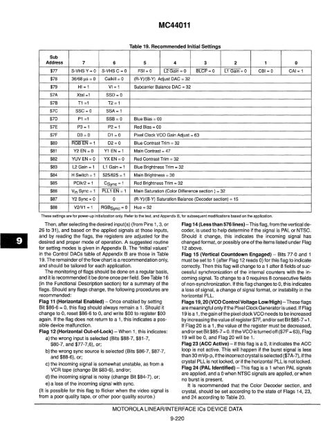
Table 19. Recommended Initial Settings<br />
Sub<br />
Address 7 6 5 4 3 2 1 0<br />
$77 S·VHS Y= a S·VHSC=O FSI = a L2 Gain = a BLCP = a L1 Gain = a CBI = a CAl = 1<br />
$78 36/681's = a Calkill = a (R-Y)/(B-Y) Adjust DAC = 32<br />
$79 HI = 1 VI= 1 Subcarrier Balance DAC = 32<br />
$7A Xtal =1 SSD=O<br />
$7B T1 =1 T2= 1<br />
$7C SSC=O SSA= 1<br />
$7D P1 =1 SSB = a Blue Bias = 00<br />
$7E P3 = 1 P2 = 1 Red Bias = 00<br />
$7F D3 =0 D1 = 0 Pixel Clock VCO Gain Adjust = 63<br />
$80 RGB EN = 1 D2= a Blue Contrast Trim = 32<br />
$81 Y2 EN =0 Y1 EN = 1 Main Contrast = 47<br />
$82 YUV EN = a YX EN =0 Red Contrast Trim = 32<br />
$83 L2 Gain = 1 L1 Gain = 1 Blue Brightness Trim = 32<br />
$84 H Switch = 1 525/625 = 1 Main Brightness = 30<br />
$85 PCIk/2 = 1 CSync = 1 Red Brightness Trim = 32<br />
$86 Vin Sync = 1 PLL1 EN = 1 Main Saturation (Color Difference section) = 32<br />
$87 Y2 Sync = a 0 (R-Y)/(B-Y) Saturation Balance (Decoder section) = 15<br />
$88 V2N1 = 1 RGBSync = 0 Hue = 32<br />
These settings are for power-up initialization only. Refer to the text, and Appendix B, for subsequent modifications based on the application.<br />
Then, after selecting the desired input(s) (from Pins 1, 3, or<br />
26 to 31), and based on the applied signals at those inputs,<br />
and by reading the flags, the registers are adjusted for the<br />
desired and proper mode of operation. A suggested routine<br />
for setting modes is given in Appendix B. The "initial values"<br />
in the Control DACs table of Appendix B are those in Table<br />
19. The remainder of the flow chart is a recommendation only,<br />
and should be tailored for each application.<br />
The monitoring of flags should be done on a regular basis,<br />
and it is recommended it be done once per field. See Table 16<br />
(in the Functional Description section) for a summary of the<br />
flags. Should any flags change, the following procedures are<br />
recommended:<br />
Flag 11 (Horizontal Enabled) - Once enabled by setting<br />
Bit $86-6 = 0, this flag should always remain a 1. Should it<br />
change to 0, reset $86-6 to 0, and write $00 to register $00<br />
again. If the flag does not return to a 1, this indicates a possible<br />
device malfunction.<br />
Flag 12 (Horizontal Out-ot-lock) - When 1, this indicates:<br />
a) the wrong input is selected (Bits $88-7, $81-7,<br />
$80-7, and $77-7,6), or;<br />
b)the wrong sync source is selected (Bits $86-7, $87-7,<br />
and $88-6), or;<br />
c) the incoming signal is somewhat unstable, as from a<br />
VCR tape (change Bit $83-6), and/or;<br />
d)the incoming signal is noisy (change Bit $84-7), or;<br />
e) a loss of the incoming signal with sync.<br />
(It is possible for this flag to flicker when the video signal is<br />
from a poor quality tape, or other poor quality source.)<br />
MOTOROLA LlNEARIINTERFACE ICs DEVICE DATA<br />
9-220<br />
Flag 14 (less than 576Iines)-This flag, from the vertical decoder,<br />
is used to help determine if the signal is PAL or NTSC.<br />
Should it change, this indicates the incoming signal has<br />
changed format, or possibly one of the items listed under Flag<br />
12 above.<br />
Flag 15 (Vertical Countdown Engaged) - Bits 77-0 and 1<br />
must be set to 1 (after Flag 12 reads 0) for this flag to indicate<br />
correctly. Then this flag will change to a 1 after 8 fields of successful<br />
synchronization of the internal counters with the incoming<br />
signal. To change to a 0 requires 8 consecutive fields<br />
of non-synchronization. If this flag changes to 0, this indicates<br />
a loss of signal, a change of signal format, or instability in the<br />
horizontal PLL.<br />
Flags 19, 20 (VCO Control <strong>Voltage</strong> low/High) - These flags<br />
are meaningful only if the Pixel Clock Generator is used. If Flag<br />
19 is a 1 , the gain of the pixel clock VCO needs to be increased<br />
by increasing the value of register$7F, and/or set Bit $85-7 =1.<br />
If Flag 20 is a 1, the value of the register must be decreased,<br />
and/or set Bit $85-7 = o. If the VCO is turned off ($7F = 63), Flag<br />
19 will be 0, and Flag 20 will be 1.<br />
Flag 23 (ACC Active) - If this flag is a 0, it indicates the ACC<br />
loop is not active. This will happen if the burst signal is less<br />
than 30 mVp-p, if the incorrect crystal is selected ($7 A-7), ilthe<br />
crystal PLL is not locked, or if the horizontal PLL is not locked.<br />
Flag 24 (PAlldentitied) - This flag is a 1 when PAL signals<br />
are applied, and a 0 when NTSC signals are applied, or when<br />
no burst is present.<br />
It is recommended that the Color Decoder section, and<br />
crystal, should be set according to the state of Flags 14, 23,<br />
and 24 according to Table 20.


