Workmanship Manual - L-3 Communications
Workmanship Manual - L-3 Communications
Workmanship Manual - L-3 Communications

Create successful ePaper yourself
Turn your PDF publications into a flip-book with our unique Google optimized e-Paper software.
Electrodynamics, Inc.<br />
1200 Hicks Road Rolling Meadows, IL 60008<br />
Tel: 847-259-0740 | Fax: 847-255-3827<br />
WORKMANSHIP<br />
MANUAL<br />
� W. Edwards Deming: “Quality is everyone's responsibility” �<br />
Page 1 of 59<br />
Doc. No. 6310034<br />
Revision: D<br />
The information contained in this document does not contain “technology” as defined by the General Technology Note in Export Administration<br />
Regulations (EAR) Supplement number 2 to Part 744 and is, therefore, considered as publicly released as defined in Part 734.7(4).<br />
This document is L-3 Electrodynamics, Inc. intellectual property. For usage outside of L-3 <strong>Communications</strong>, any unauthorized publication,<br />
reproduction, or distribution (including the saving of a copy to an electronic storage medium accessible to more than a single individual) in part or in its<br />
entirety is strictly prohibited, unless prior written consent is received from an authorized representative of L-3 Electrodynamics, Inc.
ELECTRODYNAMICS, INC Doc. No. 6310034<br />
Rolling Meadows, IL 60008 Revision: D<br />
I. RECORD OF CHANGES<br />
Rev. Pages Changed Description Of Change Date<br />
NA NA Was Preliminary Issue. 03-14-05<br />
-- NA Released For Production. 11-01-05<br />
A I, 1 - 18<br />
B 7<br />
C All<br />
D<br />
Pages 4, 14,<br />
15, 22, 34, 48-<br />
51, 53<br />
Incorporated Section 2, Renumbered<br />
Section 1 IAW CO 21468.<br />
Added Acceptable Criteria Picture For<br />
Dual Finish IAW CO 22608.<br />
Major Changes Throughout, Especially<br />
III, VI & Sections 2 – 5 IAW CO 24063.<br />
Sect.III, Revised 5 & Added 6. Added<br />
Photos for Anodized ETI Bracket &<br />
Updated 1.2.3. Added Section 6 for E<br />
and F Flanges ETIs & Renumbered<br />
Subsequent Sections. Added Photos for<br />
Armature & ML1510 Case to Electroless<br />
Nickel Plating 1.6.3. Corrected Typo<br />
from IPC-A-610 to IPC/WHMA-A-620 in<br />
2.2.4. Added Unacceptable Photo Sect.<br />
7 D.2.2.4 IAW CO 24341.<br />
Use or disclosure of data on this sheet is subject to the restriction on the title page of this document.<br />
Page 2 of 59<br />
03-01-07<br />
09-04-08<br />
07-21-10<br />
12-07-10<br />
Any revision to this document requires the approval of L-3 EDI’s Director of Quality Assurance.<br />
This document is available on L-3 EDI’s internet website. Any revsion to this document requires the<br />
<strong>Workmanship</strong> <strong>Manual</strong> on our website to be updated.
ELECTRODYNAMICS, INC Doc. No. 6310034<br />
Rolling Meadows, IL 60008 Revision: D<br />
II. TABLE OF CONTENTS<br />
I. RECORD OF CHANGES .................................................................................................. 2<br />
II. TABLE OF CONTENTS ................................................................................................... 3<br />
III. ENGINEERING DRAWINGS ............................................................................................ 4<br />
IV. ORDER OF PRECEDENCE ............................................................................................. 4<br />
V. DEFINITIONS ................................................................................................................... 4<br />
VI. GENERAL STANDARD VISUAL INSPECTION AND TEST 5<br />
SECTION 1 - PLATING, COATINGS, AND FINISHES ........................................................... 11<br />
SECTION 2 – ELECTRICAL AND ELECTRONIC ITEMS (PARTS AND ASSEMBLIES) ..... 27<br />
SECTION 3 – PLASTIC ITEMS ............................................................................................... 41<br />
SECTION 4 – VIEWING WINDOW OF EVENT COUNTERS AND HOUR METERS ............. 43<br />
SECTION 5 – 999A SERIES ETI HOUR METER AND EVENT DOUBLE UNITS .................. 46<br />
SECTION 6 – E AND F FLANGE ELAPSE TIME METER CASES (Ref: PN 400A000,<br />
410A000, 430A000, 440A000, et. al.) ............................................................. 48<br />
SECTION 7 - INDICATOR FLAGS .......................................................................................... 52<br />
SECTION 8 – PACKAGING CONTAINERS ........................................................................... 54<br />
Use or disclosure of data on this sheet is subject to the restriction on the title page of this document.<br />
Page 3 of 59
ELECTRODYNAMICS, INC Doc. No. 6310034<br />
Rolling Meadows, IL 60008 Revision: D<br />
Unless otherwise specified:<br />
III. ENGINEERING DRAWINGS<br />
1. Engineering drawings shall be interpreted in accordance with the revision of ASTM Y14.5 or<br />
ASME Y14.100 (Engineering Drawing Practices), as applicable, current at the time of its<br />
initial release; however, if a specific revision is cited then the specified revision shall govern.<br />
2. Dimensional limits apply after plating, finishing, or coating.<br />
3. For the purposes of determining conformance, all specified limits shall be absolute limits, as<br />
defined in ASTM E29 (Standard Practice for Using Significant Digits in Test Data to<br />
Determine Conformance to Specifications), unless authorized by L-3 EDI Quality Assurance.<br />
4. When surface finish limits are specified on the engineering drawing, surface finish shall be in<br />
accordance ASME B46.1 (Surface Texture (Surface Roughness, Waviness, and Lay)). See<br />
Section VI for further details.<br />
5. Any engineering drawing or workmanship interpretation questions within L-3 EDI shall be<br />
brought to the attention of the appropriate L-3 EDI personnel (i.e., supervisor, manufacturing<br />
engineering, quality assurance engineering, design engineering) for resolution by L-3<br />
Quality Assurance.<br />
6. Pursuant to L-3 EDI Form 1002 Supplier Quality Assurance Requirements Clause 1A, 1B, or<br />
1C, the requirements of this document is/shall be flowed down to our supplier partners. Any<br />
engineering drawing or workmanship interpretation questions by L-3 EDI’s supplier partners<br />
shall be brought to the attention of the appropriate L-3 EDI buyer. Form 1002 can be found<br />
on L-3 EDI’s website, or is obtainable through L-3 EDI’s Buyer.<br />
IV. ORDER OF PRECEDENCE<br />
In event of conflict, the following Order of Precedence shall govern:<br />
1. Engineering Drawing<br />
2. Purchase Order<br />
3. Referenced Specification<br />
4. L-3 EDI <strong>Workmanship</strong> <strong>Manual</strong><br />
V. DEFINITIONS<br />
The use of the words “may”, “shall”, “should” and “will” in this manual express mandatory and nonmandatory<br />
provisions as follows:<br />
1. May – Used to express a non-mandatory provision.<br />
2. Shall – Used to express a provision that is binding.<br />
3. Should – Used to express a non-mandatory provision.<br />
4. Will – Used to express a declaration of purpose on the part of the contracting agency.<br />
Use or disclosure of data on this sheet is subject to the restriction on the title page of this document.<br />
Page 4 of 59
ELECTRODYNAMICS, INC Doc. No. 6310034<br />
Rolling Meadows, IL 60008 Revision: D<br />
VI. GENERAL STANDARD VISUAL INSPECTION AND TEST<br />
Unless otherwise specified, the following standard visual inspection and test conditions shall apply:<br />
1. Facilities and Environmental Controls: Inspections shall occur in sufficiently clean and<br />
controlled environmental ambient conditions (e.g., in a foreign-object-debris-free<br />
environment at ambient temperature, humidity, and air pressure) to enable repeatable and<br />
reproducible results to be obtained commensurate with the required accuracy and criticality<br />
of the characteristic being verified. For items moved or transported from one environmental<br />
condition to another, consideration shall be given to allowing items to fully stabilize and<br />
acclimate, especially for critical inspection characteristics or those requiring a higher degree<br />
of accuracy, prior to verification.<br />
2. Normal Lighting Condition: Inspection shall be made under adequate lighting conditions<br />
(e.g., 93 foot-candles (1000 lm/m 2 ) in white fluorescent light without shadows) that does not<br />
produce/cast shadows over the item being inspected. Supplemental lighting may be<br />
necessary to assist in visual inspection.<br />
3. Duration: Typical normal visual inspection duration for cosmetic / workmanship acceptance<br />
should be 2 to 5 seconds per characteristic. Referee inspection may take longer.<br />
4. Magnification:<br />
Reference and related documents:<br />
a. WI-10-01-11 (Inspection Procedures),<br />
b. ANSI/IPC J-STD-001 (Requirements for Soldered Electrical and Electronic<br />
Assemblies).<br />
There are two inspection classifications and associated typical magnifications:<br />
a. Normal Inspection, and<br />
b. Referee Inspection.<br />
Magnification Power<br />
Normal Inspection Referee Inspection<br />
0 – 4X<br />
4 – 10X<br />
(0 – 16 Diopter)<br />
(16 – 40 Diopter)<br />
NOTE<br />
When not otherwise specified in the Inspection Procedure or other governing<br />
requirements document (e.g., IPC/EIA J-STD-001, <strong>Workmanship</strong> <strong>Manual</strong> Section<br />
(X), etc), the magnification powers to be used shall be as specified above. The<br />
above typical magnification powers should be adequate for most current L-3 EDI<br />
items.<br />
Use or disclosure of data on this sheet is subject to the restriction on the title page of this document.<br />
Page 5 of 59
ELECTRODYNAMICS, INC Doc. No. 6310034<br />
Rolling Meadows, IL 60008 Revision: D<br />
a. Normal Inspection – Normal inspection includes Receiving Inspection, Manufacturing<br />
Inspection (in-process and final), and post-production inspections (e.g., customer<br />
returns). Unless otherwise specified, the magnification power used shall be 0 – 4X. For<br />
most non-critical characteristic inspections, if the presence of a defect cannot be<br />
determined at the specified magnification level and duration (see VI, Normal Lighting),<br />
then the item shall be deemed acceptable.<br />
Most non-critical cosmetic / workmanship inspections should be verified without the use<br />
of a magnification aid. The item should be in direct line of sight 18 to 24 inches<br />
(approximately arms length) away. Items should be rotated to the left and right, or up<br />
and down, as required.<br />
b. Referee Inspection – The referee inspection magnification power of 4 – 10X shall be<br />
used only after a non-critical characteristic defect has been determined but is not<br />
completely identifiable as part of Normal Inspection, or if a defect of a critical<br />
characteristic is suspected.<br />
5. Visual Acuity: L-3 EDI: Inspection personnel eye sight requirements shall be per WI-10-<br />
01-07 (Inspection and Test Personnel Eye Examination Requirements). L-3 EDI’s Supply-<br />
Base: Inspection personnel shall possess adequate eye sight (corrected or uncorrected) to<br />
perform the visual inspections to the required degree of accuracy and repeatability.<br />
6. Surface Finish: When surface finish limits are specified on the engineering drawing,<br />
surface finish shall be interpreted as specified in Section III. It is preferred to directly<br />
measure surface finish to obtain a variable measurement value using a calibrated surface<br />
finish measurement device, such as a calibrated profilometer. Alternatively, the usage of a<br />
comparative calibrated surface finish comparator gage may be used. Comparison may by<br />
eye or tactile means.<br />
7. Adhesion of Plating, Paint, Coatings, Markings, Varnish Overcoats, and the Like:<br />
(Reference: IPC-TM-650, Test Method 2.4.1): The adhesion of plating, paint, coatings,<br />
markings, varnish overcoats, and the like shall be such that there shall be no visual<br />
evidence of removal on the tape’s adhesive surface when the following test is performed.<br />
Apply a strip of 3M Brand 600 tape or tape as specified in Commercial Item Description AA-<br />
113, Type 1, Class B (except tape may be clear) across the clean finished surface to be<br />
tested. The tape strip should be ½ inch wide by 2.0 inches long or of a size commensurate<br />
with the surface area to be tested, and shall be within the manufacturer’s specified shelf-life<br />
and storage conditions. Lightly burnish the tape to ensure removal of entrapped air and<br />
complete uniform contact. The time between the application and removal of the tape shall<br />
be less than one minute. The tape shall then be removed by pulling the tape at a right angle<br />
(90°) to the item’s surface in a single continuous, non-abrupt motion. The tape shall be<br />
examined for evidence of removal of the material being tested.<br />
Use or disclosure of data on this sheet is subject to the restriction on the title page of this document.<br />
Page 6 of 59
ELECTRODYNAMICS, INC Doc. No. 6310034<br />
Rolling Meadows, IL 60008 Revision: D<br />
8. Color and Gloss Matching: Color and gloss matching evaluation shall typically be made<br />
via visual comparison to the specified paint chip or L-3 EDI authorized physical sample. If<br />
required, especially for referee inspections, a spectrophotometer, color meter, gloss meter<br />
or other acceptable variable measurement device may be used.<br />
Paint chips and physical samples typically provide a reliable means of visual matching, but<br />
an intrinsic property of them is that their shades change over time. Moreover, the effect of<br />
ageing is usually not consistent across the range of colors, as some colors will change more<br />
than others.<br />
Adequate controls shall be established for paint chips and samples, especially to minimize<br />
any potential color change. Color change can be minimized by observing the following<br />
procedures.<br />
a. Store the color chips or samples in a cool, dark place;<br />
b. Avoid exposure of the color chips or samples to direct or scattered UV light or<br />
chemicals;<br />
c. Minimize exposure of the color chips or samples to light from any source;<br />
d. Keep the color chips and samples covered when not in use; and<br />
e. Do not touch the face of the color chips or samples with bare hands.<br />
9. Foreign Object Debris/Damage (FOD): Reference and related documents include:<br />
a. L-3 EDI QOP-09-02, Foreign Object Damage<br />
b. Form 1002 Supplier Quality Assurance Requirements, Clause 25, Foreign Object<br />
Debris/Damage (FOD) Prevention<br />
c. NAS412, Foreign Object Damage/Foreign Object Debris (FOD) Prevention<br />
Necessary controls (e.g., commensurate with the probability (i.e., risk) of FOD being<br />
introduced, the item’s criticality, etc.) shall be<br />
established to prevent items containing FOD to<br />
be shipped. Special consideration shall be<br />
given to (a) control potential sources of FOD,<br />
and (b) visually inspect potential FOD<br />
entrapment/collection areas.<br />
Use or disclosure of data on this sheet is subject to the restriction on the title page of this document.<br />
Page 7 of 59
ELECTRODYNAMICS, INC Doc. No. 6310034<br />
Rolling Meadows, IL 60008 Revision: D<br />
Potential sources of FOD include, but shall not be limited to:<br />
a. Weld and solder splatter, solder balls and slivers, flux residue;<br />
b. Metal cuttings, chips, and shavings;<br />
c. Burrs and flash;<br />
d. Hairs, fibers, and other forms of particulate matter;<br />
e. Finger oils and hand lotions;<br />
f. Cut leads of axial-leaded electronic component;<br />
g. Stripped wire insulation nibs and wire clippings;<br />
h. Threaded insert broken-off tang;<br />
i. Unsecured or unattached hardware such as screws, washers, nuts, bolts;<br />
j. Consumable items or administrative supplies such as popsicle stick and toothpick<br />
applicators, staples, paper clips;<br />
k. Food and beverages;<br />
l. Mold release compound, oils, lubricants and other forms of residue;<br />
m. Facility construction debris;<br />
n. Statically-charged / magnetized items. (Note: Some plastics are capable of<br />
becoming statically charged, and notwithstanding magnets, some metallic items are<br />
capable of becoming magnetically charged. These items when charged pose a<br />
potential deleterious effect of attracting oppositely charged items, including<br />
particulate matter.)<br />
o. Select packing materials, such as staples and packaging peanuts.<br />
After fabrication, parts and assemblies should be cleaned of any foreign material which<br />
might detract from their intended operation, function, or appearance.<br />
Areas in which FOD could collect (e.g., blind holes, pockets, wells, traps, etc.) should be<br />
visually inspected for cleanliness and FOD prior to being enclosed or packaged.<br />
L-3 EDI’s QOP-09-02 (Foreign Object Damage) is compliant with the above prescribed FOD<br />
measures. Supplier’s are encouraged to consult QOP-09-02, which is obtainable through L-<br />
3 EDI’s Buyer or NAS412 (Foreign Object Damage/Foreign Object Debris (FOD) Prevention)<br />
for benchmarking purposes to facilitate the development of their own FOD Prevention<br />
Program or taking their existing program to the next level.<br />
10. Counterfeit Parts:<br />
Reference and related documents include:<br />
a. L-3 EDI WI-02-01-02, Counterfeit Parts Risk Mitigation Plan,<br />
b. L-3 EDI Form 1002 Supplier Quality Assurance Requirement (SQAR), Clause 1<br />
regarding Suspect/Counterfeit/Substandard Parts/Items<br />
c. SAE AS5553, Counterfeit Electronic Parts; Avoidance, Detection, Mitigation, and<br />
Disposition,<br />
Use or disclosure of data on this sheet is subject to the restriction on the title page of this document.<br />
Page 8 of 59
ELECTRODYNAMICS, INC Doc. No. 6310034<br />
Rolling Meadows, IL 60008 Revision: D<br />
d. Federal Aviation Administration (FAA) Advisory Circular AC 21-29 (Detecting and<br />
Reporting Suspected Unapproved Parts).<br />
All items shall meet the original manufacturers, government/industry or regulatory authority,<br />
L-3 EDI, or other applicable second or third party full specifications, inclusive of being<br />
qualified, approved, or authorized (e.g., listed on the Qualified Product List (QPL), Qualified<br />
Manufacturer List (QML), or Buyer’s drawing/specification; NADCAP or customer special<br />
processor approved; FAA PMA/TSO approved, etc.) to manufacture or process such<br />
item(s), when required.<br />
Examples of counterfeit parts include, but shall not be limited to:<br />
a. Items which do not contain the proper internal construction<br />
(die, manufacturer, wire bonding, etc.) consistent with the<br />
ordered part.<br />
b. Items which have been used, refurbished or reclaimed, but<br />
represented as new product.<br />
c. Items which have different package style or surface<br />
plating/finish than the ordered parts.<br />
d. Items which have not successfully completed the original manufacturer’s full<br />
production and test flow, but are represented as completed product.<br />
e. Items sold as up-screened parts, which have not successfully completed upscreening.<br />
f. Items sold with modified labeling or markings intended to misrepresent the part’s<br />
form, fit, function, or grade.<br />
g. Items which are required to be manufactured or processed by a qualified, approved,<br />
or authorized manufacturer or processor (e.g., listed on the Qualified Product List<br />
(QPL), Qualified Manufacturer List (QML), or Buyer drawing/specification; NADCAP<br />
or customer special processor approved, FAA PMA/TSO approved, etc.), but who is<br />
not at the time of manufacturing or processing.<br />
Parts which are not generally considered counterfeit are those whose characteristics or<br />
specifications have been modified, but are not knowingly misrepresented, such as<br />
refinished, up-screened, or up-rated parts.<br />
In recent years, the increased levels of effort and sophistication of counterfeiters, in<br />
particular electronic part counterfeiters, have plagued the aerospace and defense<br />
electronics industry and their contractors, such as L-3 EDI. L-3 EDI and our customers take<br />
Use or disclosure of data on this sheet is subject to the restriction on the title page of this document.<br />
Page 9 of 59
ELECTRODYNAMICS, INC Doc. No. 6310034<br />
Rolling Meadows, IL 60008 Revision: D<br />
this threat very seriously. To counter this elevated risk to L-3 EDI and our customers, WI-<br />
02-01-02 (Counterfeit Parts Risk Mitigation Plan) was established, which primarily focuses<br />
on prevention. WI-02-01-02 has been promulgated in support of L-3 <strong>Communications</strong><br />
Corporate Material and Quality Operating Procedure, MQOP-001 (Counterfeit Parts Risk<br />
Mitigation), SAE AS5553 (Counterfeit Electronic Parts; Avoidance, Detection, Mitigation, and<br />
Disposition), Federal Aviation Administration (FAA) Advisory Circular AC 21-29 (Detecting<br />
and Reporting Suspected Unapproved Parts).<br />
WI-02-01-02 and Form 1002 can be found on L-3 EDI’s website, or is obtainable through L-3<br />
EDI’s Buyer to facilitate benchmarking and development of our supply-base’s Counterfeit<br />
Part Prevention and Detection Plans/Procedures or taking their existing program to the next<br />
level.<br />
As with any other requirement, L-3 EDI expects our supply-base to be in full compliance with<br />
supplier flow-down, Form 1002 Supplier Quality Assurance Requirement (SQAR), Clause 1<br />
section regarding Suspect/Counterfeit/Substandard Parts/Items.<br />
See Section 2 (Electrical And Electronic Items (Parts And Assemblies)) herein for further<br />
detailed information.<br />
Use or disclosure of data on this sheet is subject to the restriction on the title page of this document.<br />
Page 10 of 59
ELECTRODYNAMICS, INC Doc. No. 6310034<br />
Rolling Meadows, IL 60008 Revision: D<br />
SECTION 1 - PLATING, COATINGS, AND FINISHES<br />
1 PLATINGS, COATINGS, AND FINISHES<br />
1.1 ELECTROPLATING TERMINOLOGY<br />
These definitions correspond to interpretations as applied to electroplating and do not necessarily<br />
correspond to the definitions used in other plating, coating, and finish methodologies.<br />
a. Anodizing - An electrolytic oxidation process in which the surface of a metal, when anodic,<br />
is converted to a coating having desirable protective, decorative, or functional properties<br />
(reference: ASTM B 374 and 6310058)<br />
b. Barrel Processing - Mechanical, chemical, cleaning or electrolytic treatment of articles in<br />
bulk or in a rotating, oscillating, or otherwise moving container (reference: ASTM B 374).<br />
c. Base (Basis) Metal - Material upon which coatings are deposited (reference: ASTM B 374).<br />
d. Black Oxide - A finish on metal produced by immersing a metal in hot oxidizing salts or salt<br />
solution (reference: ASTM B 374 and 6310058)<br />
e. Blister - A dome-shaped imperfection or defect, resulting from loss of adhesion between a<br />
metallic deposit and the substrate (reference: ASTM B 374).<br />
f. Bright Dip – A solution used to produce a bright surface on a metal (reference: ASTM B<br />
374).<br />
g. Color Uniformity - Surface color varying in uniformity resulting in spots, blotches and<br />
striations of different color.<br />
h. Contamination - An inclusion of foreign material detectable on surface of the item.<br />
i. Conversion Coating - A coating produced by chemical or electrochemical treatment of a<br />
metallic surface that gives a superficial layer containing a compound of the metal (reference:<br />
ASTM B 374).<br />
j. Crack(s) - A fracture passing completely through the thickness or section of an item.<br />
k. Crazing - A network of fine hairline cracks in a coating (reference: ASTM B 374).<br />
l. Deformed - A departure from normal shape greater than the dimensional tolerance. Items<br />
often deform out of round, out of square, twisted, warped, bent or flattened.<br />
m. Dent - A depression with no removal of material or change in surface texture.<br />
n. Dual Finish - An item that has two different finishes as specified on the drawing.<br />
o. Electroplating – The electro deposition of an adherent metallic coating upon an electrode<br />
for the purpose of securing a surface a surface with properties or dimensions different from<br />
those of the base metal (reference: ASTM B 374).<br />
p. Flash – Related to molded items - Excess material adhering to item.<br />
Use or disclosure of data on this sheet is subject to the restriction on the title page of this document.<br />
Page 11 of 59
ELECTRODYNAMICS, INC Doc. No. 6310034<br />
Rolling Meadows, IL 60008 Revision: D<br />
q. Flash – Related to electro parting – A very thin electro-deposit used for a final coat: for<br />
intermediate coatings of the same nature, use strike (reference: ASTM B 374).<br />
r. Gouges - The result of scooping out of material by another object.<br />
s. Masking - Various materials applied to specific areas of items to prevent coatings from<br />
being deposited (reference: ASTM B 374).<br />
t. Nicks - Sharp surface indentation caused by impact of a foreign object. Parent material is<br />
normally displaced, seldom separated. Non-fill/Void - An incomplete item due to insufficient<br />
material.<br />
u. Orange Peel - A finish resembling the dimpled appearance of an orange peel (reference:<br />
ASTM B 374).<br />
v. Pickling - The removal of oxides or other compounds from a metal surface by means of a<br />
pickle (an acid solution) (reference: ASTM B 374).<br />
w. Pit - A small depression or cavity produced in a metal surface during electrodeposition or by<br />
corrosion (reference: ASTM B 374).<br />
x. Pin Hole - A small sharply defined hole in surface of item.<br />
y. Rack, Plating - A frame for suspending and carrying current to articles during plating and<br />
related operations (reference: ASTM B 374 and 6310058).<br />
z. Sealed (Anodic) Coating – in anodized aluminum, an anodic oxide coating on aluminum<br />
that has been treated in an aqueous or steam medium resulting in reduced porosity of the<br />
coating (reference: ASTM B 374).<br />
aa. Scuff - A mark caused by abrasion, which changes surface smoothness or texture.<br />
ab. Smut – A black powdery finish that is easily removed with a mild abrasive.<br />
ac. Strike - A thin film of metal to be followed by other coatings (reference: ASTM B 374).<br />
ad. Strip - To remove a coating from the basis metal or undercoat (reference: ASTM B 374).<br />
ae. Surface Discoloration - An apparent surface inconsistency in material evidenced by the<br />
appearance of light to dark streaks.<br />
af. Underplating - Application of a metallic coating layer between the basis metal or substrate<br />
and the topmost metallic coating or coatings. The thickness of such an undercoating is<br />
usually greater than 0.8 µm (30 µin). This is in contrast to strikes or flashes, whose<br />
thicknesses are generally much smaller (reference: ASTM B 545).<br />
ag. Void – A defective area in which a part of the basis material or under layer is visible after<br />
final coating (reference: ASTM B 374).<br />
ah. Whiskers – Metallic filamentary growths, often microscopic, sometimes formed during<br />
electro-deposition and sometimes spontaneously during storage or service, after finishing.<br />
Use or disclosure of data on this sheet is subject to the restriction on the title page of this document.<br />
Page 12 of 59
ELECTRODYNAMICS, INC Doc. No. 6310034<br />
Rolling Meadows, IL 60008 Revision: D<br />
1.2 ANODIZING<br />
Reference: MIL-A-8625F Amendment 1 (a.k.a. A1) - Anodic Coatings for Aluminum and Aluminum<br />
Alloys, Paragraph(s): 3.6 Class 2, 3.13, 3.13.1, 3.3.4 and 6.20.<br />
1.2.1 Acceptable <strong>Workmanship</strong><br />
a. MIL-A-8625: 3.6 Class 2. When class 2 is specified in the contract or purchase order<br />
(see 6.2 per MIL-A-8625), the anodic coating shall be uniformly dyed or pigmented by<br />
exposure to a solution of a suitable type dye or stain. The color on wrought alloys shall<br />
be uniform. Cast alloys may exhibit dye bleed-out or lack of color (or color uniformity)<br />
associated-with-the inherent porosity of the casting. The dyes and pigments used shall<br />
not be damaging to the anodic coatings.<br />
b. MIL-A-8625: 3.13 <strong>Workmanship</strong>. Except for touch up areas In accordance with 3.3.4<br />
and as noted below, the applied anodic coating shall be continuous, smooth, adherent,<br />
uniform in appearance, free from powdery areas, loose films, breaks, scratches and<br />
other defects which will reduce the serviceability of anodized parts or assembles.<br />
Differences in anodic coating appearance resulting from inherent base metal<br />
differences in a component such as the presence of welds, components containing cast<br />
and machined surfaces, and differences in grain size within a forging shall not be cause<br />
to reject the anodic coating unless otherwise specified in the contract or purchase order<br />
(see 6.2 per MIL-A-8625). Slight discoloration from dripping or rundown of the sealing<br />
solution from designed crevices in a component shall be allowed.<br />
c. MIL-A-8625: 3.13.1 Contact marks. The size and number of contact marks shall be at<br />
a minimum consistent with good practice (see 6.14 per MIL-A-8625). If a specific<br />
location for contact marks is desired; the-location shall be specified on the contract or<br />
purchase order (see 6.2 per MIL-A-8625).<br />
d. MIL-A-8625: 3.3.4 Touch UP (mechanical damage and contact marks). Unless<br />
otherwise specified (see 6.2 per MIL-A-8625), mechanically damaged areas from which<br />
the anodic coating has been removed without damage to the item may be touched up<br />
using chemical conversion materials approved on QPL-81706 for Class 1A coatings<br />
and the applicable method of application. Touch up shall apply only to inadvertent<br />
mechanical damage such as scratch marks. For Type I, IB and II coatings, touch up<br />
shall only be allowed in areas which will not be subjected to abrasion (see 6.1.1 per<br />
MIL-A-8625). The mechanically damaged area(s) shall not exceed 5 percent of the<br />
total anodized area of the item or touch up shall not be permitted. When specified in<br />
the contract or purchase order (see 6.2 per MIL-A-8625), contact marks shall be<br />
touched up using the above method required for mechanical damage.<br />
Use or disclosure of data on this sheet is subject to the restriction on the title page of this document.<br />
Page 13 of 59
ELECTRODYNAMICS, INC Doc. No. 6310034<br />
Rolling Meadows, IL 60008 Revision: D<br />
1.2.2 Packaging<br />
a. Coated surfaces shall be protected from damage during shipment and storage.<br />
b. When applicable, egg crate shipping containers are recommended during all storage<br />
and handling of the components. Each item should be individually packaged to prevent<br />
contact of adjacent items (e.g., in their own egg crate cell).<br />
1.2.3 Illustrations<br />
The following illustrations depict “Acceptable” and “Unacceptable” workmanship results.<br />
A<br />
B<br />
C<br />
Acceptable <strong>Workmanship</strong> Unacceptable <strong>Workmanship</strong><br />
Anodizing Uniform<br />
No Foreign Material On Threads<br />
No Anodizing Missing On Threads<br />
Anodizing Not Uniform<br />
Foreign Material On Threads<br />
Anodizing Missing On Threads<br />
Use or disclosure of data on this sheet is subject to the restriction on the title page of this document.<br />
Page 14 of 59
ELECTRODYNAMICS, INC Doc. No. 6310034<br />
Rolling Meadows, IL 60008 Revision: D<br />
D<br />
E<br />
F<br />
Acceptable <strong>Workmanship</strong> Unacceptable <strong>Workmanship</strong><br />
Anodizing Not<br />
Scratched/Nicked/Peeling/Flaking or<br />
Pitted<br />
No/Slight Dark Spots<br />
Scratched/Nicked Anodizing<br />
Peeling/Flaking Pitted<br />
Dark Spots<br />
Note: Part Shown Is Clear Anodized per MIL-A-8625, Type I, Class 1 (Ref. PN 098A60 & 098A61).<br />
Use or disclosure of data on this sheet is subject to the restriction on the title page of this document.<br />
Page 15 of 59
ELECTRODYNAMICS, INC Doc. No. 6310034<br />
Rolling Meadows, IL 60008 Revision: D<br />
1.3 BLACK OXIDE<br />
Reference: MIL-DTL-13924D Notice 1 – Coating, Oxide, Black, for Ferrous Metals, Paragraph(s):<br />
3.7, 4.4.1.<br />
1.3.1 Acceptable <strong>Workmanship</strong><br />
a. MIL-DTL-13924: 3.7 Coverage and color. Class 1, 2, 3, and 4 coatings (see 1.2 per<br />
MIL-DTL-13924) shall cover the basis metal completely and shall pass the smut test.<br />
The color shall be a uniform black. A slight amount of smut, which is inherent in the<br />
process, shall not be cause for rejection. There shall be no indication of any reddishbrown<br />
or green smut when tested as in 4.4.1. Smut "spottiness" shall be classified as<br />
unsatisfactory and shall require reprocessing.<br />
b. MIL-DTL-13924: 4.4.1 Smut test. The test shall be made prior to application of<br />
corrosion preventive compound or after vapor degreasing. Each black oxide coated<br />
piece shall be inspected visually under strong light to assure a satisfactory appearance.<br />
Each sample shall also be wiped with a clean white cloth for indications of smut (see<br />
3.7 MIL-DTL-13924). A slight amount of smut which is inherent in the process is<br />
acceptable for all classes of coatings and shall not be cause for rejection.<br />
1.3.2 Packaging<br />
a. Coated surfaces shall be protected from damage during shipment and storage.<br />
b. When applicable, egg crate shipping containers are recommended during all storage<br />
and handling of the components. Each item should be individually packaged to prevent<br />
contact of adjacent items (e.g., in their own egg crate cell).<br />
1.3.3 Illustrations<br />
The following illustrations depict “Acceptable” and “Unacceptable” workmanship results.<br />
A<br />
Acceptable <strong>Workmanship</strong> Unacceptable <strong>Workmanship</strong><br />
Black Oxide Is Uniform<br />
Use or disclosure of data on this sheet is subject to the restriction on the title page of this document.<br />
Page 16 of 59
ELECTRODYNAMICS, INC Doc. No. 6310034<br />
Rolling Meadows, IL 60008 Revision: D<br />
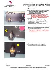
1.4 CHROMATE (A.K.A. IRRIDITE, ALODINE OR CHEMICAL CONVERSION COATING)<br />
Reference: MIL-DTL-5541F - Chemical Conversion Coatings on Aluminum and Aluminum Alloys,<br />
Paragraph(s): 3.5 and 6.8.<br />
1.4.1 Engineering Drawing Call Out: In the event the engineering drawing does not call out a<br />
specific chromate color, the color shall be yellow. Clear chromate shall only be used when<br />
explicitly specified on the engineering drawing primarily due to the inherent difficulties of<br />
visually discerning the presence of clear chromate.<br />
1.4.2 Acceptable <strong>Workmanship</strong><br />
a. MIL-DTL-5541: 3.5 Appearance. The chemical conversion coating shall be continuous<br />
in appearance and visibly discernible in daylight. It shall be free from areas of powdery<br />
or loose coating, voids, scratches, flaws, and other defects or damages which reduce<br />
the serviceability of items or are detrimental to the protective value and paint bonding<br />
characteristics. The size and number of contact marks shall be minimal, consistent with<br />
good practice. If specified in the contract or order, contact marks shall be touched up<br />
with MIL-DTL-81706 material approved on QPL- 81706 for the applicable type; class,<br />
form, and method to prevent localized corrosion (see 6.4 and 6.8 MIL-DTL-5541).<br />
b. MIL-DTL-5541: 6.8 Visual appearances. The simplest way to evaluate a conversion<br />
coating is to observe color, continuity in appearance; smoothness and adhesion to the<br />
base metal (see 3.5 MIL-DTL-5541). Visual examination is performed to ensure that<br />
proper cleaning and coating procedures were used such that a coating with sufficient<br />
protection exists over the entire item. Materials qualified under MIL-DTL-81706<br />
produce coatings that range in color from clear/colorless to iridescent yellow, brown,<br />
gray, or blue. It may be possible to develop acceptable color levels for a particular<br />
coating system by use of color chips. The following circumstances may exist that relate<br />
to color uniformity:<br />
a. When several alloys are processed with the same conversion chemical, color may<br />
vary from alloy to alloy.<br />
b. Due to the high level of impurities and oxidation on the surfaces of aluminum welds<br />
and castings, color may not be as uniform as that obtained by treating wrought<br />
alloys.<br />
c. Dark spots may result from dripping or rundown of the conversion chemicals when<br />
the items are lifted out of the treatment tank. A small amount of spotting does not<br />
result in coating degradation but must be minimized by quickly rinsing the items<br />
after treatment, and use of proper racking techniques (reference 6310058).<br />
1.4.3 Packaging<br />
a. Coated surfaces shall be protected from damage during shipment and storage.<br />
Use or disclosure of data on this sheet is subject to the restriction on the title page of this document.<br />
Page 17 of 59
ELECTRODYNAMICS, INC Doc. No. 6310034<br />
Rolling Meadows, IL 60008 Revision: D<br />
b. When applicable, egg crate shipping containers are recommended during all storage<br />
and handling of the components. Each item should be individually packaged to prevent<br />
contact of adjacent items (e.g., in their own egg crate cell).<br />
1.4.4 Illustrations<br />
The following illustrations depict “Acceptable” and “Unacceptable” workmanship results.<br />
A<br />
B<br />
Acceptable <strong>Workmanship</strong> Unacceptable <strong>Workmanship</strong><br />
Chromate Is Uniform<br />
Minor Dark Spots<br />
Chromate Is Not Uniform<br />
Excessive Amount of Scratches (No More<br />
Than 5 Isolated Spots)<br />
Use or disclosure of data on this sheet is subject to the restriction on the title page of this document.<br />
Page 18 of 59
ELECTRODYNAMICS, INC Doc. No. 6310034<br />
Rolling Meadows, IL 60008 Revision: D<br />
1.5 DUAL FINISH<br />
1.5.1 Definitions<br />
a. Dual Finish – An item that has two different types of finishes, coatings, or platings.<br />
1.5.2 Acceptable <strong>Workmanship</strong><br />
a. There shall be no contamination on the finish.<br />
b. The separating line for the finishes shall be as specified on the engineering drawing.<br />
c. Each finish shall be as specified in this manual.<br />
1.5.3 Packaging<br />
a. Coated surfaces shall be protected from damage during shipment and storage.<br />
b. When applicable, egg crate shipping containers are recommended during all storage<br />
and handling of the components. . Each item should be individually packaged to<br />
prevent contact of adjacent items (e.g., in their own egg crate cell).<br />
1.5.4 Illustrations<br />
The following illustrations depict “Acceptable” and “Unacceptable” workmanship results. Shown<br />
below are items that are dual finished with black anodized and clear chromate.<br />
A<br />
B<br />
Acceptable <strong>Workmanship</strong> Unacceptable <strong>Workmanship</strong><br />
No Foreign Material/Discoloration<br />
Anodizing Completely Removed<br />
Foreign Material/Severe Discoloration<br />
Anodizing Not Completely Removed<br />
Use or disclosure of data on this sheet is subject to the restriction on the title page of this document.<br />
Page 19 of 59
ELECTRODYNAMICS, INC Doc. No. 6310034<br />
Rolling Meadows, IL 60008 Revision: D<br />
C<br />
Acceptable <strong>Workmanship</strong> Unacceptable <strong>Workmanship</strong><br />
Minor Discoloration Immediately Around<br />
Center Hole<br />
1.6 ELECTROLESS NICKEL<br />
Reference: MIL-DTL-26074F Notice 1 – Coatings, Electroless Nickel, Paragraph(s): 3.6.2. (Note:<br />
Per Notice 1, MIL-DTL-26074F has been superseded by either MIL-DTL-32119 and SAE AMS-C-<br />
26074 depending upon the application. For L-3 EDI’s applications, SAE AMS-C-26074 shall be the<br />
superseding specification.)<br />
1.6.1 Acceptable <strong>Workmanship</strong><br />
a. The nickel coating shall be smooth, adherent, and free from visible blisters, pits, nodules,<br />
porosity, cracks and other defects.<br />
1.6.2 Packaging<br />
a. Coated surfaces shall be protected from damage during shipment and storage.<br />
b. When applicable, egg crate shipping containers are recommended during all storage and<br />
handling of the components. . Each item should be individually packaged to prevent<br />
contact of adjacent items (e.g., in their own egg crate cell).<br />
1.6.3 Illustrations<br />
The following illustrations depict “Acceptable” and “Unacceptable” workmanship results.<br />
A<br />
Acceptable <strong>Workmanship</strong> Unacceptable <strong>Workmanship</strong><br />
Nickel is Uniform<br />
Use or disclosure of data on this sheet is subject to the restriction on the title page of this document.<br />
Page 20 of 59
ELECTRODYNAMICS, INC Doc. No. 6310034<br />
Rolling Meadows, IL 60008 Revision: D<br />
E<br />
F<br />
Acceptable <strong>Workmanship</strong> Unacceptable <strong>Workmanship</strong><br />
Slight Surface Abrasion Marks<br />
(ML1510 Case PN 400185 Example Shown)<br />
AMATURE PN 038C120<br />
No Peeling, Pitting, Discoloration or<br />
Visible Oxidation (i.e., Corrosion)<br />
Moderate Plating Discoloration/Oxidation<br />
(Likely Substrate Bleed-Thru/Plating Too<br />
Thin)<br />
Use or disclosure of data on this sheet is subject to the restriction on the title page of this document.<br />
Page 21 of 59
ELECTRODYNAMICS, INC Doc. No. 6310034<br />
Rolling Meadows, IL 60008 Revision: D<br />
G<br />
Acceptable <strong>Workmanship</strong> Unacceptable <strong>Workmanship</strong><br />
Slight Discoloration / Oxidation (i.e.,<br />
Corrosion)<br />
Severe Discoloration / Oxidation<br />
(Likely Substrate Bleed-Thru/Plating Too<br />
Thin)<br />
Use or disclosure of data on this sheet is subject to the restriction on the title page of this document.<br />
Page 22 of 59
ELECTRODYNAMICS, INC Doc. No. 6310034<br />
Rolling Meadows, IL 60008 Revision: D<br />
1.7 ELECTRODEPOSITED TIN<br />
Reference: ASTM B 545 – Standard Specification for Electrodeposited Coatings of Tin,<br />
Paragraph(s): 6.3 - 6.5.<br />
1.7.1 Engineering Drawing Call Out: In the event the engineering drawing does not call out a<br />
specific tin composition, the tin composition shall contain a minimum of 3% lead.<br />
1.7.2 Acceptable <strong>Workmanship</strong><br />
a. ASTM B 545: 6.3 Appearance — Tin coatings shall have the characteristic appearance,<br />
including surface texture (4.3 per ASTM B 545), for the process used. The appearance<br />
shall be uniform throughout, insofar as the basis metal will permit. They shall be<br />
adherent and visually free of blisters, pits, peeled areas, cracks, nodules, and unplated<br />
areas. They shall not be stained or discolored. Flow-brightened coatings shall be free<br />
of dewetted areas and beads. All surfaces shall be substantially free of grease or oil<br />
used in the flow-brightening process.<br />
b. ASTM B 545: 6.4 All tin-coated articles shall be clean and undamaged. When<br />
necessary, preliminary samples showing the finish shall be supplied to and approved by<br />
the purchaser. Where a contact mark is inevitable, its location shall be subject to<br />
agreement between the supplier and the purchaser.<br />
c. ASTM B 545: 6.5 Thickness of Coatings—Tin coatings on articles shall conform to the<br />
thickness requirements specified in 4.2 of ASTM B 545 as to the minimum thickness on<br />
significant surfaces.<br />
d. Coatings shall be free of visible mechanical damage and similar gross defects when<br />
viewed at up to 4X magnification.<br />
1.7.3 Packaging<br />
a. Coated surfaces shall be protected from damage during shipment and storage.<br />
b. When applicable, egg crate shipping containers are recommended during all storage<br />
and handling of the components. Each item should be individually packaged to<br />
prevent contact of adjacent items (e.g., in their own egg crate cell).<br />
Use or disclosure of data on this sheet is subject to the restriction on the title page of this document.<br />
Page 23 of 59
ELECTRODYNAMICS, INC Doc. No. 6310034<br />
Rolling Meadows, IL 60008 Revision: D<br />
c.<br />
1.7.4 Illustrations<br />
The following illustrations depict “Acceptable” and “Unacceptable” workmanship results.<br />
A<br />
B<br />
Acceptable <strong>Workmanship</strong> Unacceptable <strong>Workmanship</strong><br />
Tin Is Uniform<br />
Slight Surface Marring<br />
Use or disclosure of data on this sheet is subject to the restriction on the title page of this document.<br />
Page 24 of 59
ELECTRODYNAMICS, INC Doc. No. 6310034<br />
Rolling Meadows, IL 60008 Revision: D<br />
1.8 ELECTRODEPOSITED ZINC<br />
Reference: ASTM B633 (& ASTM B86 for Zinc Die Castings) – Standard Specification for<br />
Electrodeposited Coatings of Zinc on Iron and Steel, Paragraph(s): 7.2, 7.3, and 7.5.<br />
1.8.1 Acceptable <strong>Workmanship</strong><br />
a. ASTM B633: 7.2 Adhesion —The adhesion of the coating shall be such that when<br />
examined in accordance with 10.2 of ASTM B633, the coating shall not show<br />
separation from the basis metal at the interface.<br />
b. 7.3 Luster — Unless otherwise specified by the purchaser, a bright, semi-bright, or dull<br />
finish shall be acceptable.<br />
c. 7.4 Corrosion Resistance — Zinc coatings with Types II, III, V, and VI treatments shall<br />
show neither corrosion products of zinc nor basis metal corrosion products at the end of<br />
the test periods describe in Table 2 of ASTM B633 when tested by continuous exposure<br />
to salt spray in accordance with 10.3 of ASTM B633. The appearance of corrosion<br />
products when examined with 20/20 eyesight at normal reading distance shall be cause<br />
for rejection, except that white corrosion products 6 mm or less from the edges of<br />
specimens shall not constitute failure. For corrosion resistance requirements, see<br />
Table 2 of ASTM B633.<br />
d. <strong>Workmanship</strong> — The surface of the electroplated article shall be uniform in<br />
appearance, free of visible coating defects, such as blisters, pits, roughness, nodules,<br />
burning, cracks, or unplated areas, and other defects that will affect the function of the<br />
coating. The coating shall not be stained or discolored. However, superficial staining<br />
that result from rinsing or slight discoloration resulting from any drying or baking<br />
operation to relieve hydrogen embrittlement shall not be cause for rejection. On articles<br />
in which a visible contact mark is unavoidable, its position shall be that chosen by the<br />
purchaser. The electroplated article shall be clean and free of damage.<br />
1.8.2 Packaging<br />
a. Coated surfaces shall be protected from damage during shipment and storage.<br />
b. When applicable, egg crate shipping containers are recommended during all storage<br />
and handling of the components. . Each item should be individually packaged to prevent<br />
contact of adjacent items (e.g., in their own egg crate cell).<br />
1.9 PAINTING<br />
Reference: MIL-PRF-22750F, Performance Specification, Coating, Epoxy, High-Solids (VOC –<br />
Compliant), Paragraph(s): 3.7.2.<br />
Use or disclosure of data on this sheet is subject to the restriction on the title page of this document.<br />
Page 25 of 59
ELECTRODYNAMICS, INC Doc. No. 6310034<br />
Rolling Meadows, IL 60008 Revision: D<br />
1.9.1 Acceptable <strong>Workmanship</strong><br />
a. MIL-PRF-22750F: 3.7.2 Surface appearance. The coating shall dry to a smooth,<br />
uniform surface, free from runs, sags, bubbling; streaks, hazing, seeding, dusting,<br />
floating, mottling, or other film defect when applied to test panels in accordance with 4.5<br />
through 4.5.2 of MIL-PRF-22750.<br />
1.9.2 Packaging<br />
a. Coated surfaces shall be protected from damage during shipment and storage.<br />
b. When applicable, egg crate shipping containers are recommended during all storage<br />
and handling of the components. Each item should be individually packaged to prevent<br />
contact of adjacent items (e.g., in their own egg crate cell).<br />
1.9.3 Illustrations<br />
The following illustrations depict “Acceptable” and “Unacceptable” workmanship results.<br />
A<br />
Acceptable <strong>Workmanship</strong> Unacceptable <strong>Workmanship</strong><br />
Paint Is Uniform<br />
Use or disclosure of data on this sheet is subject to the restriction on the title page of this document.<br />
Page 26 of 59
ELECTRODYNAMICS, INC Doc. No. 6310034<br />
Rolling Meadows, IL 60008 Revision: D<br />
SECTION 2 – ELECTRICAL AND ELECTRONIC ITEMS (PARTS AND ASSEMBLIES)<br />
2. Electrical And Electronic Parts and Assemblies<br />
Section 2 covers electrical and electronic parts and assemblies (e.g., Active and Passive<br />
Electronic Components, Cut-To-Length or Stripped Wire or Cable, Cable Assemblies, Wiring<br />
Harnesses, Interconnects, Printed Circuit/Wiring Boards (PCBs/PWBs), Tabbing Boards,<br />
Interconnect Assemblies, Printed Card/Printed Wiring Assemblies (PCAs/PWAs) and<br />
Tabbing Board Assemblies including their parent end-items, such as: Data Recorders,<br />
Electronic Safe Arm Devices, Hour Meters, Event Counters, Fault Indicators, Readers, Led<br />
Indicators, etc.). PCA’s/PWA’s are often also called Circuit Card Assemblies (CCA’s).<br />
2.1 Active/Passive Electronic Component (A/PEC) Authenticity / Counterfeit Prevention<br />
And Detection<br />
2.1.1 Scope: This subsection applies to A/PECs that are later sold to our customers either as-is<br />
or incorporated into an end-item/finished good, regardless of whether such parts are<br />
procured as discrete items, or integrated into electronic assemblies or equipment by L-3 EDI<br />
or our supply-base.<br />
While the primary focus of this subsection and WI-02-01-02 (Counterfeit Part Risk Mitigation<br />
Plan) is to mitigate the risk of counterfeit A/PECs from entering our customers’ supply chain,<br />
this shall not preclude the usage and tailoring of these documents to manage the risk of<br />
counterfeit parts of other commodities.<br />
2.1.2 Definitions: See WI-02-01-02, Counterfeit Part Risk Mitigation Plan, for definitions.<br />
2.1.3 Reference and Related Documents:<br />
a. L-3 EDI Form 1002, Supplier Quality Assurance Requirements, Clause 1.*<br />
b. L-3 EDI WI-02-01-02, Counterfeit Parts Risk Mitigation Plan.*<br />
c. IDEA-STD-1010, Acceptability of Electronic Components Distributed in the Open<br />
Market.<br />
d. SAE AS5553, Counterfeit Electronic Parts; Avoidance, Detection, Mitigation, and<br />
Disposition (DoD Adopted).<br />
* Note: External to L-3 EDI, these documents are available on L-3 EDI’s website at http://www.l-<br />
3com.com/edi/supplier_info.htm or http://www.l-3com.com/edi/customer_info.htm.<br />
2.1.4 General<br />
See VI, Counterfeit Parts for further information.<br />
Based on a determination of consumers risk, a representative sample<br />
(up to and including 100% inspection) should be visually examined from<br />
each lot (date code) of APECs procured from an Independent<br />
Distributor, as a mininmum, at a recommended magnification of up to<br />
40X dependent upon the part’s size and characteristic being verified.<br />
Use or disclosure of data on this sheet is subject to the restriction on the title page of this document.<br />
Page 27 of 59
ELECTRODYNAMICS, INC Doc. No. 6310034<br />
Rolling Meadows, IL 60008 Revision: D<br />
L-3 EDI requires all Turn Key Contract Manufacturers buying APECS for Card/Printed<br />
Wiring Assemblies (CCAs/PWAs), Tabbing Board Assemblies, and other types of Electronic<br />
Assemblies to have an established Counterfeit Parts Risk Mitigation Plan documenting the<br />
risk mitigation strategy and methodologies to be employed that is acceptable to L-3 EDI.<br />
Turn Key Contract Manufacturers are encouraged to model their control plan based upon<br />
SAE AS5553 available from the Society of Automotive Engineers (SAE) at www.sae.org.<br />
IDEA-STD-1010, Acceptability of Electronic Components Distributed in the Open Market,<br />
may be used as a best-practice guideline for conducting visual inspection and verification of<br />
APECs authenticity.<br />
2.1.5 Criteria<br />
Examples of visual accept/reject critieria and tell-tale counterfeit indications include, but<br />
shall not be limited to:<br />
a. Poor quality part marking. Marking is faded. Type style, font size or color change is<br />
evident or data on a single line is located at different heights.<br />
b. Item shows evidence of wear or prior use.<br />
c. Chips on the package which may indicate excessive or careless handling.<br />
d. Scratches on the surface of the package.<br />
e. Inconsistent lead/termination plating coverage.<br />
f. Leads/terminations bent.<br />
g. Leads/terminations show evidence of previous attachment (solder present, metal<br />
upset or marred).<br />
h. Leads/terminations show arcing, discoloration, pitting, or corrosion.<br />
i. Leads/terminations are loose, missing or show metal/plating upset.<br />
j. Lead/Termination finish designator in the part number not consistent with the<br />
terminal finish on the part.<br />
k. Inconsistent texture/color or unleveled coating on the top and/or bottom sides of the<br />
part.<br />
l. Rough surface texture in the normally smooth Pin 1 indicators area.<br />
m. Cracks in the package that may signify thermal stress.<br />
n. Cracks in the seals around leads/terminations.<br />
o. Mold pin marking areas not smooth, clean, or from part-to-part not consistent.<br />
p. Presence of numerous date codes on one individual/unit container. i.e., reel, tube,<br />
tray, etc. or within the lot in general.<br />
q. Item is unusually boxed or packed.<br />
r. Markings inconsistent with standard OEM marking content and format.<br />
s. Originality and applicability of Certificates of Conformance or other certifications/data<br />
should be examined against the supplied item, including, but not limited to:<br />
i. Lot and/or date codes on the packaging match the lot and/or date codes on<br />
the parts.<br />
ii. Manufacturer’s logo or label is absent, or does not match that which is shown<br />
on their website, on previous shipments, or on the parts.<br />
Use or disclosure of data on this sheet is subject to the restriction on the title page of this document.<br />
Page 28 of 59
ELECTRODYNAMICS, INC Doc. No. 6310034<br />
Rolling Meadows, IL 60008 Revision: D<br />
iii. Poor use of English, misspelled words, alterations, or changes to the<br />
documentation.<br />
iv. The use of correction fluid or correction tape is evident.<br />
v. Type style, size or pitch change is evident.<br />
vi. The document is not signed, initialed when required, is excessively faded or<br />
unclear (indicating multiple, sequential copying) or data is missing.<br />
vii. The name of the document approver or his title cannot be determined, or<br />
typed approval name and approval signature do not match.<br />
viii. Certification or test results are identical between items when normal<br />
variations should be expected.<br />
ix. Document traceability is not clear. The documentation should be traceable to<br />
the items procured.<br />
x. Documentation is not delivered as required on the purchase order or is in an<br />
unusual format.<br />
xi. Data on a single line is located at different heights.<br />
xii. Documents copied.<br />
xiii. Corrections are not properly lined-out, initialed and dated.<br />
xiv. Text on page ends abruptly and number of pages conflicts with transmittal.<br />
xv. Lines on forms are bent, broken, or interrupted indicating data has been<br />
deleted or exchanged (cut and paste).<br />
NOTE<br />
A free website named ic photos providing photographs of A/PECs can be used for<br />
authentication comparison purposes.<br />
For L-3 EDI personnel, report any suspect-counterfeit/counterfeit part to management.<br />
For L-3 EDI supply-base, report any suspect-counterfeit/counterfeit part to L-3 EDI’s Buyer.<br />
2.1.6 Illustrations<br />
A<br />
The following illustrations depict “Unacceptable” results.<br />
Photos Courtesy of L-3 Cincinnati Electronics<br />
Unacceptable <strong>Workmanship</strong><br />
Remarking<br />
Use or disclosure of data on this sheet is subject to the restriction on the title page of this document.<br />
Page 29 of 59
ELECTRODYNAMICS, INC Doc. No. 6310034<br />
Rolling Meadows, IL 60008 Revision: D<br />
B<br />
C<br />
D<br />
E<br />
Unacceptable <strong>Workmanship</strong><br />
Part Suspect of Previously Being Used; Residual Solder & Bent Leads<br />
Missing/Bent Leads<br />
Corrosion/Oxidation on Leads<br />
Exposed Copper on Leads<br />
Use or disclosure of data on this sheet is subject to the restriction on the title page of this document.<br />
Page 30 of 59
ELECTRODYNAMICS, INC Doc. No. 6310034<br />
Rolling Meadows, IL 60008 Revision: D<br />
F<br />
G<br />
H<br />
Unacceptable <strong>Workmanship</strong><br />
Suspect Counterfeit on Right<br />
Different Manufacturer Marking On Top and Bottom of Same Component<br />
Top Appears Recoated After Chemical Cleaning<br />
(Pay Close Attention to Consistency of Marking Font, Color & Alignment)<br />
Use or disclosure of data on this sheet is subject to the restriction on the title page of this document.<br />
Page 31 of 59
ELECTRODYNAMICS, INC Doc. No. 6310034<br />
Rolling Meadows, IL 60008 Revision: D<br />
I<br />
J<br />
Unacceptable <strong>Workmanship</strong><br />
Inconsistent Mold Pins<br />
Dirty Mold Pin Areas<br />
Suspect Black Topping; Noticeable Color/Gloss Difference Between Top & Side<br />
Use or disclosure of data on this sheet is subject to the restriction on the title page of this document.<br />
Page 32 of 59
ELECTRODYNAMICS, INC Doc. No. 6310034<br />
Rolling Meadows, IL 60008 Revision: D<br />
K<br />
L<br />
Unacceptable <strong>Workmanship</strong><br />
Considerable Difference in Lead Thickness & Shape; Suggests Original Plating May<br />
Have Been Removed and Re-Plated<br />
Deformed Part Edge<br />
Likely Because of<br />
Sanding<br />
Roughness/Sanding<br />
Marks<br />
Component Body Surface Roughness/Sanding Evident<br />
Manufacturer’s Indent<br />
Mold Area Almost<br />
Sanded Completely<br />
Away<br />
Use or disclosure of data on this sheet is subject to the restriction on the title page of this document.<br />
Page 33 of 59
ELECTRODYNAMICS, INC Doc. No. 6310034<br />
Rolling Meadows, IL 60008 Revision: D<br />
2.2 Cut-To-Length or Stripped Wire or Cable, Cable Assemblies, Wiring Harnesses, and<br />
Other Interconnect Devices/Assemblies<br />
2.2.1 Scope: This subsection applies to Cut-To-Length or Stripped Wire or Cable, Cable<br />
Assemblies, Wiring Harnesses, and Other Interconnect Devices/Assemblies, excluding<br />
those in 2.3 and 2.4 below.<br />
2.2.2 Defect Definitions: Unless otherwise specified, defect definitions shall be as specified in<br />
ANSI/ IPC J-STD-001 (Requirements for Soldered Electrical and Electronic Assemblies<br />
(DoD Adopted)) and/or IPC / WHMA-A-620 (Requirements and Acceptance for Cable and<br />
Wire Harness Assemblies).<br />
2.2.3 Reference and Related Documents:<br />
a. ANSI / IPC J-STD-001, Requirements for Soldered Electrical and Electronic<br />
Assemblies (DoD Adopted).<br />
b. IPC / WHMA-A-620, Requirements and Acceptance for Cable and Wire Harness<br />
Assemblies.<br />
2.2.4 Applicability<br />
The following applicability shall govern:<br />
a. If an L-3 EDI engineering drawing, specification or other governing document<br />
specifies ANSI / IPC J-STD-001 and does NOT specify IPC / WHMA-A-620, both<br />
ANSI / IPC J-STD-001 and ANSI / IPC-A-620shall apply via virtue of this<br />
workmanship manual.<br />
b. If an L-3 EDI engineering drawing, specification or other governing document does<br />
NOT specify either ANSI / IPC J-STD-001 or IPC / WHMA-A-620, both ANSI / IPC J-<br />
STD-001 and IPC / WHMA-A-620 shall apply via virtue of this workmanship manual.<br />
c. The Testing Requirements in Section 19 (Testing) of IPC/WHMA-A-620 shall apply<br />
as follows:<br />
i. L-3 EDI “Make” Items: Since L-3 EDI does not typically provide to our<br />
customers Cut-To-Length or Stripped Wire or Cable, Cable Assemblies,<br />
Wiring Harnesses, and other Interconnect Devices/Assemblies as a<br />
dedicated end-item, Section 19 shall be used a as a guideline to develop our<br />
overall test program for a specific end-item.<br />
ii. L-3 EDI “Buy” Items: Unless otherwise specified in writing by L-3 EDI’s<br />
Buyer, L-3 EDI’s suppliers shall comply with the test requirements specified<br />
therein ONLY for Cable Assemblies, Wiring Harnesses, and applicable<br />
similar Interconnect Devices/Assemblies.<br />
Use or disclosure of data on this sheet is subject to the restriction on the title page of this document.<br />
Page 34 of 59
ELECTRODYNAMICS, INC Doc. No. 6310034<br />
Rolling Meadows, IL 60008 Revision: D<br />
2.2.5 Order of Precedence:<br />
In the event of conflict, the following order of precedence shall apply<br />
a. Contract or purchase order.<br />
b. L-3 EDI engineering drawing or specification.<br />
c. ANSI / IPC J-STD-001.<br />
d. IPC / WHMA-A-620.<br />
2.2.6 <strong>Workmanship</strong> Requirements:<br />
Unless otherwise specified, the following workmanship requirements shall apply, as a<br />
minimum.<br />
<strong>Workmanship</strong> Standard<br />
ANSI / IPC J-STD-001<br />
IPC / WHMA-A-620 ¥<br />
† L-3 EDI Purchase Orders (POs) for Systems Products Groups’ (SPG) purchases can be<br />
readily distinguished from Components Products Groups’ (CPG) POs by the presence of<br />
Project Numbers and often Contract Numbers in the body or line item of the SPG PO.<br />
¥ See 2.2.4.c.<br />
2.3 Printed Circuit Boards<br />
Systems Product Group<br />
(SPG) Items<br />
(e.g., Data Recorders,<br />
ESAFs) †<br />
Class 3<br />
(High Performance<br />
Electronic Products)<br />
Class 3 ¥<br />
(High Performance<br />
Electronic Products)<br />
2.3.1 Scope: This subsection applies to Printed Circuit/Wiring Boards (PCBs/PWBs), and<br />
Tabbing Boards, including those classified as rigid, flex, or rigid-flex, and tabbing boards.<br />
2.3.2 Defect Definitions: Unless otherwise specified, defect definitions shall be as specified in<br />
ANSI / IPC-A-600 (Acceptability of Printed Boards).<br />
2.3.3 Reference and Related Documents:<br />
a) ANSI / IPC-A-600, Acceptability of Printed Boards<br />
b) IPC-2221, Generic Standard on Printed Board Design* †<br />
c) IPC-2222, Rigid Organic Printed Board Structure Design* †<br />
d) IPC-2223, Flexible Printed Board Structure Design* †<br />
e) IPC-6011, General Performance Specification for Printed Boards* ¥<br />
Components Product Group<br />
(CPG) Items<br />
(e.g., Hour Meters, Event<br />
Counters, Fault Indicators,<br />
Readers, LED Indicators) †<br />
Class 1<br />
(General Electronic Products)<br />
Class 1 ¥<br />
(General Electronic Products)<br />
Use or disclosure of data on this sheet is subject to the restriction on the title page of this document.<br />
Page 35 of 59
ELECTRODYNAMICS, INC Doc. No. 6310034<br />
Rolling Meadows, IL 60008 Revision: D<br />
f) IPC-6012, Qualification and Performance Specification for Rigid Printed Boards* ¥<br />
g) IPC-6013, Qualification and Performance Specification for Flexible Printed Boards* ¥<br />
* Typical L-3 EDI engineering “baseline” design guidelines. Not intended to be all inclusive.<br />
† Included as part of what is commonly known as the IPC-2220 series of design specifications.<br />
¥ Included as part of what is commonly known as the IPC-6010 series of qualification and<br />
performance specifications.<br />
2.3.4 Applicability<br />
The following applicability shall govern:<br />
a. If an L-3 EDI engineering drawing, specification or other governing document<br />
specifies an IPC printed board specification (e.g., an IPC-6010 series specification)<br />
and does NOT specify IPC-A-600, both the cited IPC specification and ANSI / IPC-A-<br />
600 shall apply via virtue of this workmanship manual.<br />
b. If an L-3 EDI engineering drawing, specification or other governing document does<br />
NOT specify an IPC printed board specification (e.g., an IPC-6010 series<br />
specification), ANSI / IPC-A-600 should be used as a guidance specification.<br />
2.3.5 Order of Precedence:<br />
In the event of conflict, the following order of precedence shall apply:<br />
a. Contract or purchase order.<br />
b. L-3 EDI engineering drawing or specification.<br />
c. ANSI / IPC-A-600.<br />
2.3.6 <strong>Workmanship</strong> Requirements:<br />
Unless otherwise specified, the following workmanship requirements shall apply, as a<br />
minimum.<br />
<strong>Workmanship</strong> Standard<br />
ANSI / IPC -A-600<br />
Systems Product Group<br />
(SPG) Items<br />
(e.g., Data Recorders,<br />
ESAFs) †<br />
Class 3<br />
(High Performance<br />
Electronic Products)<br />
Components Product Group<br />
(CPG) Items<br />
(e.g., Hour Meters, Event<br />
Counters, Fault Indicators,<br />
Readers, LED Indicators) †<br />
Class 1<br />
(General Electronic Products)<br />
† L-3 EDI Purchase Orders (POs) for Systems Products Groups’ (SPG) purchases can be<br />
readily distinguished from Components Products Groups’ (CPG) POs by the presence of<br />
Project Numbers and often Contract Numbers in the body or line item of the SPG PO.<br />
Use or disclosure of data on this sheet is subject to the restriction on the title page of this document.<br />
Page 36 of 59
ELECTRODYNAMICS, INC Doc. No. 6310034<br />
Rolling Meadows, IL 60008 Revision: D<br />
2.4 Circuit Card Assemblies<br />
2.4.1 Scope: This subsection applies to Circuit Card Assemblies (CCA’s) which may also be<br />
called Printed Circuit /Printed Wiring Assemblies (PCAs/PWAs), and Tabbing Board<br />
Assemblies.<br />
2.4.2 Defect Definitions: Unless otherwise specified, defect definitions shall be as specified in<br />
ANSI/ IPC J-STD-001 (Requirements for Soldered Electrical and Electronic Assemblies<br />
(DoD Adopted)) and/or IPC-A-610 (Acceptability of Electronic Assemblies (DoD Adopted)),<br />
as applicable.<br />
2.4.3 Reference and Related Documents:<br />
a) ANSI / IPC J-STD-001, Requirements for Soldered Electrical and Electronic<br />
Assemblies (DoD Adopted).<br />
b) IPC-A-610, Acceptability of Electronic Assemblies (DoD Adopted).<br />
2.4.4 Applicability:<br />
The following applicability shall govern:<br />
a. If an L-3 EDI engineering drawing or specification specifies ANSI / IPC J-STD-001<br />
and does NOT specify ANSI / IPC-A-610, both ANSI / IPC J-STD-001 and ANSI /<br />
IPC-A-610 shall apply via virtue of this workmanship manual.<br />
b. If an L-3 EDI engineering drawing or specification does NOT specify either ANSI /<br />
IPC J-STD-001 or ANSI / IPC-A-610, both ANSI / IPC J-STD-001 and ANSI / IPC-A-<br />
610 shall apply via virtue of this workmanship manual.<br />
c. If a requirements document specifies a legacy or cancelled military or industry<br />
standard the following guidance should apply.<br />
i. For L-3 EDI, this should be confirmed with our customer in advance.<br />
ii. For L-3 EDI’s supply-base, this should be confirmed with L-3 EDI in advance<br />
and written authorization should be provided before proceeding.<br />
Use or disclosure of data on this sheet is subject to the restriction on the title page of this document.<br />
Page 37 of 59
ELECTRODYNAMICS, INC Doc. No. 6310034<br />
Rolling Meadows, IL 60008 Revision: D<br />
Legacy Standard<br />
(Any Revision)<br />
WS-6536<br />
DOD-STD-2000<br />
MIL-STD-2000<br />
MIL-STD-454 †<br />
IPC-S-815<br />
Superseding Requirements<br />
(See 2.4.4c)<br />
ANSI / IPC J-STD-001 ANSI / IPC-A-610<br />
Class 3 (High Performance<br />
Electronic Products)<br />
Class 3 (High Performance<br />
Electronic Products)<br />
† MIL-STD-454 has been superseded by MIL-HDBK-454. MIL-HDBK-454, Guideline 5<br />
(Soldering) specifies soldering to be in accordance with ANSI / IPC J-STD-001 without citing a<br />
specific “Class”. The same requirements above for MIL-STD-454 shall apply to any MIL-HDBK-<br />
454 citations.<br />
2.4.5 Order of Precedence:<br />
In the event of conflict, the following order of precedence shall apply<br />
a. Contract or purchase order.<br />
b. L-3 EDI engineering drawing or specification.<br />
c. ANSI / IPC J-STD-001.<br />
d. ANSI / IPC-A-610.<br />
2.4.6 <strong>Workmanship</strong> Requirements:<br />
Unless otherwise specified, the following workmanship requirements shall apply, as a<br />
minimum.<br />
<strong>Workmanship</strong> Standard<br />
ANSI / IPC J-STD-001<br />
ANSI / IPC-A-610<br />
Systems Product Group<br />
(SPG) Items<br />
(e.g., Data Recorders,<br />
ESAFs) †<br />
Class 3<br />
(High Performance<br />
Electronic Products)<br />
Class 3<br />
(High Performance<br />
Electronic Products)<br />
Components Product Group<br />
(CPG) Items<br />
(e.g., Hour Meters, Event<br />
Counters, Fault Indicators,<br />
Readers, LED Indicators) †<br />
Class 1<br />
(General Electronic Products)<br />
Class 1<br />
(General Electronic Products)<br />
Use or disclosure of data on this sheet is subject to the restriction on the title page of this document.<br />
Page 38 of 59
ELECTRODYNAMICS, INC Doc. No. 6310034<br />
Rolling Meadows, IL 60008 Revision: D<br />
† L-3 EDI Purchase Orders (POs) for Systems Products Groups’ (SPG) purchases can be readily<br />
distinguished from Components Products Groups’ (CPG) POs by the presence of Project Numbers<br />
and often Contract Numbers in the body or line item of the SPG PO.<br />
2.5 Rework, Repair and Modifications of Electronic Components, Printed Circuit Boards,<br />
and Circuit Card Assemblies<br />
2.5.1 Scope: This subsection applies to Electronic Components, Printed Circuit/Wiring Boards<br />
(PCBs/PWBs), and Circuit Card Assemblies (CCA’s), including Tabbing Boards and Tabbing<br />
Boards Assemblies. CCA’s are often also called Printed Circuit/Wiring Assemblies<br />
(PCAs/PWAs).<br />
2.5.2 Defect Definitions: Unless otherwise specified, defect definitions shall be as specified in<br />
2.3 and 2.4 above.<br />
2.5.3 Reference and Related Documents:<br />
a. IPC-7711, Rework of Electronic Assemblies.<br />
b. IPC-7721, Repair and Modification of Printed Boards and Electronic Assemblies.<br />
c. L-3 EDI Form 1002, Supplier Quality Assurance Requirements, Clause 4,<br />
Nonconforming Material (NCM) and Material Review Authority (MRA).<br />
d. QOP-13-01, Control of Nonconforming Product.<br />
2.5.4 Applicability:<br />
The following applicability shall govern:<br />
a. Commercial Off-The-Shelf (COTS) Items: Subsection 2.5 shall not apply to COTS<br />
items.<br />
b. Rework: Unless otherwise specified, any applicable required rework shall be<br />
accomplished in accordance with, or at the very least modeled after, IPC-7711.<br />
c. Repair: Repairs shall NOT be allowed without prior customer written authority or<br />
approval.<br />
i. From an L-3 EDI Perspective: “Customer” shall mean the customer with<br />
whom L-3 EDI has a contract or purchase order. Unless otherwise specified,<br />
as a standard practice, L-3 EDI shall make every reasonable attempt to adopt<br />
or model to the maximum extent practical any applicable repair activities in<br />
accordance with IPC-7721.<br />
ii. From an L-3 EDI Supply-Base Perspective: “Customer” shall mean L-3 EDI.<br />
d. Modifications: Modifications shall NOT be allowed without prior customer written<br />
authority or approval, or L-3 EDI Configuration Management authorization (e.g., a<br />
released engineering “modification” drawing), as applicable.<br />
Use or disclosure of data on this sheet is subject to the restriction on the title page of this document.<br />
Page 39 of 59
ELECTRODYNAMICS, INC Doc. No. 6310034<br />
Rolling Meadows, IL 60008 Revision: D<br />
i. From an L-3 EDI Perspective: “Customer” shall mean the customer with<br />
whom L-3 EDI has a contract or purchase order. Unless otherwise specified,<br />
as a standard practice, L-3 EDI shall make every reasonable attempt to adopt<br />
or model to the maximum extent practical any applicable modification<br />
activities in accordance with IPC-7721.<br />
ii. From an L-3 EDI Supply-Base Perspective: “Customer” shall mean L-3 EDI.<br />
2.5.5 Order of Precedence:<br />
In the event of conflict, the following order of precedence shall apply:<br />
a. Contract or purchase order.<br />
b. L-3 EDI engineering drawing or specification.<br />
c. IPC-7711 or IPC-7721.<br />
2.5.6 <strong>Workmanship</strong> Requirements:<br />
Unless otherwise specified, the following workmanship requirements shall apply, as a<br />
minimum.<br />
a. Rework: By definition, satisfactorily completed rework will meet the original<br />
specification and workmanship requirements specified in 2.3 and 2.4 above.<br />
b. Repair: By definition, the workmanship requirements specified in 2.3 and 2.4 above<br />
may not necessarily be applicable.<br />
c. Modification: By definition, the workmanship requirements specified in 2.3 and 2.4<br />
above may not necessarily be applicable.<br />
d. Process Controls: Adequate process controls shall exist for any rework,<br />
modification, or repair activities, including post-rework or post-repair inspection and<br />
test.<br />
e. Inspection and Test: All reworks, modifications, and repairs shall be inspected<br />
and/or tested after completion of the rework, modification, or repair to established<br />
and documented criteria. Unless otherwise specified, inspection or test shall be to<br />
the original criteria to the maximum extent practical.<br />
Use or disclosure of data on this sheet is subject to the restriction on the title page of this document.<br />
Page 40 of 59
ELECTRODYNAMICS, INC Doc. No. 6310034<br />
Rolling Meadows, IL 60008 Revision: D<br />
SECTION 3 – PLASTIC ITEMS<br />
3 Plastic Items<br />
3.1 Scope: This section covers both molded and machined plastic items.<br />
3.2 Defect Definitions:<br />
a. Blow-Hole - A cavity or hole in the molded item typically formed due to the air or gas<br />
venting to the surface during curing process. In comparison to a pit, a blow-hole is<br />
characterized by either a continuous bottom or continuous (e.g., 360°) side wall NOT<br />
being evident.<br />
b. Blush - Discoloration or change in gloss.<br />
c. Broken - General damage. Example bent and broken tabs or ribs.<br />
d. Bubbles - Void pockets, bulge or protrusion.<br />
e. Burns - Brown marks and streaks.<br />
f. Contamination - Large areas of discoloration from foreign matter or foreign material<br />
embedded in the surface.<br />
g. Cracking - Stress induced splitting or fissures causing separation of material.<br />
h. Crazing - Multiple tiny cracks due to stress exerted on the item.<br />
i. Delamination - Separation of layers of plastic.<br />
j. Discoloration - Any change from original color. Unintended and inconsistent color.<br />
k. Drag Marks - Cluster of scratches from plastic dragging against mold detail.<br />
l. Flash - Excess plastic at parting line or mating surface of the mold. Normally very thin<br />
and flat protrusion of plastic along an edge of a item.<br />
m. Gouge - Surface imperfection due to abrasion that removes small amount of material.<br />
n. Haze - Cloudiness on a transparent item.<br />
o. Nicks - Like gouges but of short length.<br />
p. Orange Peel - Rippled or mottled appearance view able as concentric lines.<br />
q. Pit – A crater-like imperfection on the surface of the item. In comparison to a blowhole.<br />
a pit is characterized by a continuous bottom and continuous (e.g., 360°) side<br />
wall being evident.<br />
r. Scratch - Surface imperfection due to abrasion that removes small amounts of<br />
material.<br />
s. Short Shot - Missing plastic due to incomplete filling of the mold cavity.<br />
t. Sink - Surface depression caused by non uniform material solidification and shrinkage.<br />
u. Specks - Small discolored points of matter embedded in the surface.<br />
v. Splay - Off color streaking.<br />
3.3 Gate and Surface Conditions:<br />
a. The items gate location and size (e.g., length x width x height) shall be as specified on<br />
the engineering drawing.<br />
b. If a gate location and size (e.g., length x width x height) is not specified on the<br />
engineering drawing, it is the responsibility of the supplier to obtain in writing<br />
acceptable gate locations and size from L-3 EDI’s buyer prior to producing the item.<br />
Use or disclosure of data on this sheet is subject to the restriction on the title page of this document.<br />
Page 41 of 59
ELECTRODYNAMICS, INC Doc. No. 6310034<br />
Rolling Meadows, IL 60008 Revision: D<br />
c. Unless otherwise specified on the engineering drawing, ALL three of the following flash<br />
criteria shall be satisfied:<br />
Criteria Engineering<br />
Drawings Specifying<br />
That “No Flash” Is<br />
Acceptable<br />
1. Flash shall be within the<br />
specified limits of size for<br />
the item’s feature (e.g.,<br />
item’s width)<br />
2. Flash itself shall be within<br />
its specified limits of size<br />
(i.e., L X W X H) and<br />
location.<br />
3. Flash shall be firmly<br />
attached along its entire<br />
length.<br />
Other Engineering<br />
Drawings<br />
Requirement, if any, as specified on the<br />
engineering drawing.<br />
ELECTRODYNAMICS, INC Doc. No. 6310034<br />
Rolling Meadows, IL 60008 Revision: D<br />
SECTION 4 – VIEWING WINDOW OF EVENT COUNTERS AND HOUR METERS<br />
4 Viewing Window Of Event Counters And Hour Meters<br />
4.1 This workmanship section covers all windows used to readily enable viewing of the Event<br />
Counters and Hour Meters readouts.<br />
4.2 In general, Hour Meters workmanship criteria shall be in accordance with MIL-M-7793 (Meter,<br />
Time Totalizing), and Event Counters in accordance with MIL-I-8974 (Indicators, Event<br />
Counting).<br />
4.3 The purpose of this workmanship standard is to provide specific criteria regarding what is<br />
acceptable related to streaks, smears, or markings.<br />
a. Streaks: See photographs below for detail illustrations of acceptable streaks. The<br />
viewing window shall be of such condition to readily enable clearly viewing the<br />
number wheel digits without visual distortion.<br />
b. Foreign Objects: See photos below for detail illustrations of unacceptable foreign<br />
object debris (FOD). Viewing window shall be free from debris such as fibers, hairs,<br />
flux, solder, and/or any other type of debris that could possibly entangle in the<br />
internal gearing mechanisms (reference Section VI, FOD).<br />
4.4 Illustrations<br />
The following illustrations depict “Acceptable” and “Unacceptable” workmanship results.<br />
A<br />
Acceptable <strong>Workmanship</strong> Unacceptable <strong>Workmanship</strong><br />
Clear Streaks In Viewing Window Display<br />
NOT Distorting Number Wheels<br />
Foreign Material - Hair/Fiber In Viewing<br />
Window Display<br />
Use or disclosure of data on this sheet is subject to the restriction on the title page of this document.<br />
Page 43 of 59
ELECTRODYNAMICS, INC Doc. No. 6310034<br />
Rolling Meadows, IL 60008 Revision: D<br />
B<br />
C<br />
D<br />
Acceptable <strong>Workmanship</strong> Unacceptable <strong>Workmanship</strong><br />
Partial Clear Streak in Viewing Window<br />
Display NOT Distorting Number Wheels<br />
Streak In Viewing Window NOT Distorting<br />
Number Wheels<br />
Foreign Material - Hair/Fiber In Viewing<br />
Window Display<br />
Foreign Material - Flux In Viewing<br />
Window Display<br />
Foreign Material - Particulate Matter In<br />
Viewing Window Display<br />
Use or disclosure of data on this sheet is subject to the restriction on the title page of this document.<br />
Page 44 of 59
ELECTRODYNAMICS, INC Doc. No. 6310034<br />
Rolling Meadows, IL 60008 Revision: D<br />
E<br />
Acceptable <strong>Workmanship</strong> Unacceptable <strong>Workmanship</strong><br />
Foreign Material - Solder Curl In Viewing<br />
Window Display<br />
Use or disclosure of data on this sheet is subject to the restriction on the title page of this document.<br />
Page 45 of 59
ELECTRODYNAMICS, INC Doc. No. 6310034<br />
Rolling Meadows, IL 60008 Revision: D<br />
SECTION 5 – 999A SERIES ETI HOUR METER AND EVENT DOUBLE UNITS<br />
5 999A SERIES ETI HOUR METER AND EVENT DOUBLE UNITS<br />
5.1 Potting Terminology:<br />
a. Blow-Hole - A cavity or hole in the potting typically formed due to the air or gas<br />
venting to the surface during curing process. A blow-hole is characterized by a<br />
continuous bottom or 360°of side wall NOT being evident.<br />
b. Pit - A crater-like imperfection on the surface of the item. In comparison to a blowhole,<br />
a pit is characterized by a continuous bottom and 360°of side wall being<br />
evident.<br />
c. Sink - Surface depression caused by non uniform potting solidification and<br />
shrinkage.<br />
5.2 Potting workmanship requirements shall be as specified in Section 6. All other discrete<br />
individual workmanship requirements apply; see applicable sections.<br />
5.3 Illustrations<br />
The following illustrations depict “Acceptable” and “Unacceptable” workmanship results.<br />
A<br />
B<br />
Acceptable <strong>Workmanship</strong> Unacceptable <strong>Workmanship</strong><br />
Corner Separation<br />
Severe Separation Around Face<br />
Use or disclosure of data on this sheet is subject to the restriction on the title page of this document.<br />
Page 46 of 59
ELECTRODYNAMICS, INC Doc. No. 6310034<br />
Rolling Meadows, IL 60008 Revision: D<br />
C<br />
D<br />
E<br />
Acceptable <strong>Workmanship</strong> Unacceptable <strong>Workmanship</strong><br />
Pits; Bottom & Sides Can Be Seen And<br />
Are Continuous<br />
Pit; Bottom & Sides Can Be Seen And<br />
Are Continuous<br />
Blow Hole With No Visible Bottom<br />
Blow Hole With No Visible Bottom<br />
Sink; Depth > .08<br />
Use or disclosure of data on this sheet is subject to the restriction on the title page of this document.<br />
Page 47 of 59
ELECTRODYNAMICS, INC Doc. No. 6310034<br />
Rolling Meadows, IL 60008 Revision: D<br />
SECTION 6 – E AND F FLANGE ELAPSE TIME METER CASES (Ref: PN 400A000, 410A000,<br />
430A000, 440A000, et. al.)<br />
A<br />
B<br />
Acceptable <strong>Workmanship</strong> Unacceptable <strong>Workmanship</strong><br />
Superficial Marring/Scratches on Face<br />
(No Metal Displacement)<br />
Slight Dents Edge of Face<br />
(Slight Metal Displacement)<br />
Dents/Depressions on Face (Metal<br />
Displaced)<br />
Dents/Depressions on Face (Metal<br />
Displaced) & Pinhole > 1/32”<br />
Use or disclosure of data on this sheet is subject to the restriction on the title page of this document.<br />
Page 48 of 59
ELECTRODYNAMICS, INC Doc. No. 6310034<br />
Rolling Meadows, IL 60008 Revision: D<br />
C<br />
D<br />
Acceptable <strong>Workmanship</strong> Unacceptable <strong>Workmanship</strong><br />
Pin Hole in Face 1/32”<br />
Pin Hole in Face > 1/32”<br />
(Painted to Illustrate Pin Hole)<br />
Use or disclosure of data on this sheet is subject to the restriction on the title page of this document.<br />
Page 49 of 59
ELECTRODYNAMICS, INC Doc. No. 6310034<br />
Rolling Meadows, IL 60008 Revision: D<br />
E<br />
Acceptable <strong>Workmanship</strong> Unacceptable <strong>Workmanship</strong><br />
Color Variance/Discoloration (Pre-Plating)<br />
Use or disclosure of data on this sheet is subject to the restriction on the title page of this document.<br />
Page 50 of 59
ELECTRODYNAMICS, INC Doc. No. 6310034<br />
Rolling Meadows, IL 60008 Revision: D<br />
F<br />
Acceptable <strong>Workmanship</strong> Unacceptable <strong>Workmanship</strong><br />
O-Ring<br />
Groove Area<br />
No Nicks/Dings Evident Especially In<br />
O-Ring Groove<br />
Small Isolated Ding Outside of O-Ring<br />
Groove - NOT Exceeding Surface<br />
Finish/Dimensional Requirements<br />
From Small Isolated Dings Inside of O-<br />
Ring Groove (Top) Progressing To<br />
Severe Scratches/Nicks (Bottom) –<br />
Use or disclosure of data on this sheet is subject to the restriction on the title page of this document.<br />
Page 51 of 59
ELECTRODYNAMICS, INC Doc. No. 6310034<br />
Rolling Meadows, IL 60008 Revision: D<br />
7 INDICATOR FLAGS<br />
SECTION 7 - INDICATOR FLAGS<br />
7.1 Scope: <strong>Workmanship</strong> standard covers all flag indicating components installed in end-items<br />
such as, but not limited to, CI70, CI75, MI51, MI57, and MI61 units.<br />
7.2 Illustrations<br />
The following illustrations depict “Acceptable” and “Unacceptable” workmanship results.<br />
Criteria based on visual examples shown with a maximum 10X magnification per VI,<br />
Magnification.<br />
A<br />
B<br />
C<br />
Acceptable <strong>Workmanship</strong> Unacceptable <strong>Workmanship</strong><br />
Minor Single Speck - Colored<br />
Minor Single Speck – Not Colored<br />
Minor Color Variation Across Item<br />
Use or disclosure of data on this sheet is subject to the restriction on the title page of this document.<br />
Page 52 of 59
ELECTRODYNAMICS, INC Doc. No. 6310034<br />
Rolling Meadows, IL 60008 Revision: D<br />
D<br />
Acceptable <strong>Workmanship</strong> Unacceptable <strong>Workmanship</strong><br />
Rough Edge (Within Limits of Size)<br />
Rough Edge<br />
Use or disclosure of data on this sheet is subject to the restriction on the title page of this document.<br />
Page 53 of 59
ELECTRODYNAMICS, INC Doc. No. 6310034<br />
Rolling Meadows, IL 60008 Revision: D<br />
8. PACKAGING CONTAINERS<br />
SECTION 8 – PACKAGING CONTAINERS<br />
8.1 Scope: 49CFR 173.28 Reusable Plywood Shipping Crates.<br />
8.2 Acceptable <strong>Workmanship</strong> (Reference: 49CFR 173.28).<br />
Prior to container reuse, containers shall be verified to satisfy the following conditions:<br />
a. NO panel separation. Panels shall be firmly secured. See Note 1.<br />
b. NO cleat separation. Cleats shall be firmly secured. See Note 1.<br />
c. NO water damage or rot reducing the container’s structural integrity. See Note 1.<br />
d. NO wood rupture or plywood layer separation reducing the container’s structural<br />
integrity. See Note 1.<br />
e. NO excessive splits, breaks or cracks, or wood checking especially around<br />
fasteners, or other wood damage reducing the container’s structural integrity. See<br />
Note 1.<br />
f. NO excessive fastener holes (e.g., nail holes from previous nailing of the lid) or other<br />
damage that would compromise the secure fastening of the lid. See Note 1.<br />
g. NO unsecured fasteners. Fastener heads shall not be raised above the surrounding<br />
surface (e.g., nail head popping). See Note 1.<br />
h. NO fasteners that appear NOT to be original (i.e., not consistent with the other<br />
fasteners indicating possible rework). See Note 1.<br />
i. NO incompatible residue. The interior and exterior shall free from residue, including<br />
mold or fungi. Staining is acceptable as long as it does NOT reduce the container’s<br />
structural integrity. (Note: wood discoloration to a gray color is natural.) See Note 1.<br />
j. NO sharp objects protruding into the interior of the container. See Note 2.<br />
k. NO particulate material in the interior of the container. See Note 3.<br />
Notes:<br />
1. NOT reconditionable / reworkable.<br />
2. May be reconditioned / reworked ONLY if NOT part of the original container.<br />
3. May be reconditioned / reworked.<br />
Use or disclosure of data on this sheet is subject to the restriction on the title page of this document.<br />
Page 54 of 59
ELECTRODYNAMICS, INC Doc. No. 6310034<br />
Rolling Meadows, IL 60008 Revision: D<br />
8.3 Definitions<br />
a. Checking - Cracks that occur on the ends and surfaces of wood during drying are<br />
known as checks. Since the ends and surfaces dry first, they tend to shrink first but<br />
are restrained by the swollen core. This result in stresses building up near the<br />
surfaces which, if they become too great, will cause the wood to check.<br />
b. Cleats – See Figure 1.<br />
c. Panel – See Figure 1.<br />
Figure 1. Crate Anatomy.<br />
Use or disclosure of data on this sheet is subject to the restriction on the title page of this document.<br />
Page 55 of 59
ELECTRODYNAMICS, INC Doc. No. 6310034<br />
Rolling Meadows, IL 60008 Revision: D<br />
A<br />
B<br />
8.3.1 Illustrations<br />
The following illustrations depict “Unacceptable” workmanship.<br />
Unacceptable <strong>Workmanship</strong><br />
Use or disclosure of data on this sheet is subject to the restriction on the title page of this document.<br />
Page 56 of 59
ELECTRODYNAMICS, INC Doc. No. 6310034<br />
Rolling Meadows, IL 60008 Revision: D<br />
C<br />
D<br />
Unacceptable <strong>Workmanship</strong><br />
Use or disclosure of data on this sheet is subject to the restriction on the title page of this document.<br />
Page 57 of 59
ELECTRODYNAMICS, INC Doc. No. 6310034<br />
Rolling Meadows, IL 60008 Revision: D<br />
E<br />
F<br />
Unacceptable <strong>Workmanship</strong><br />
Use or disclosure of data on this sheet is subject to the restriction on the title page of this document.<br />
Page 58 of 59
ELECTRODYNAMICS, INC Doc. No. 6310034<br />
Rolling Meadows, IL 60008 Revision: D<br />
G<br />
Unacceptable <strong>Workmanship</strong><br />
Use or disclosure of data on this sheet is subject to the restriction on the title page of this document.<br />
Page 59 of 59