Model 9040-T(A) - L-3 Communications
Model 9040-T(A) - L-3 Communications
Model 9040-T(A) - L-3 Communications

Create successful ePaper yourself
Turn your PDF publications into a flip-book with our unique Google optimized e-Paper software.
• Baseband to Baseband<br />
• IF to Baseband<br />
• Baseband to IF<br />
• IF to IF<br />
FEATURES<br />
• Variable Input Tuning Range<br />
10 kHz to 400 MHz<br />
• 200 MHz Bandwidth Available for<br />
1000 MHz Input CF<br />
• Input IF Fixed Frequencies of<br />
.455/.85/1.7/6.8/8.83/10.7/13.6/21.4/<br />
27.2/70/140/160/300/400 and<br />
1000 MHz<br />
• Variable Output Tuning Range of<br />
10 kHz to 400 MHz<br />
• Output Fixed Frequencies of<br />
3/6/10/15/20/21.4/25/30/40/50/70140/<br />
160/300/400 MHz<br />
• Thirteen Standard Band<br />
widths of 1/2/4/6/8/10/12/20/30/40/<br />
50/60/80 MHz and a Bypass Mode<br />
• Nine Selectable Output equalizers<br />
Centered at 3/6/10/15/20/25/ 30/40<br />
and 50 MHz<br />
• Coherent Frequency Conversion<br />
• Synthesized Tuning 1 kHz<br />
Increments<br />
• Imageless Mixers and Saw Filters<br />
Utilized<br />
www.L-3Com.com/COMINT<br />
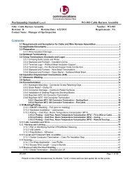
<strong>Model</strong> <strong>9040</strong>-T(A)<br />
Versatile Frequency Converter<br />
PRODUCT DESCRIPTION<br />
The <strong>Model</strong> <strong>9040</strong>-T(A) is a synthesized frequency converter that is tunable<br />
on both the input and output in 1 kHz steps. The excellent performance<br />
characteristics of the imageless mixers make the wide tuning range<br />
possible while controlling spurious signals and maintaining tight amplitude<br />
requirements. Distortion due to group delay variations is minimized by the<br />
use of multi-section group delay equalizers. Any specifi ed input can be<br />
converted to any specifi ed output and the unit functions as an upconverter<br />
or downconverter per the selected parameters. Each unit has IF to IF, IF to<br />
Baseband, Baseband to IF and Baseband to Baseband capabilities.<br />
The unit has the capability to convert any input frequency in the range of<br />
10 KHz to 400 MHz including fi xed IF frequencies of .455/.85/1.7/6.8/8.83/<br />
10.7/13.6/21.4/27.2/70/140/160/300/400 and 1000 MHz, to any output<br />
frequency in the range of 10 kHz to 400 MHz including fi xed IF output<br />
frequencies of 3/6/10/15/20/21.4/25/30/40/50/70/140/160/300 and<br />
400 MHz. Imageless mixers are used for conversions of frequencies up<br />
to the 120 MHz band edge. The image rejecting mixers are employed to<br />
suppress undesired mixer products and to improve the signal to noise ratio<br />
by suppression of the image band. Group delay equalizers are provided<br />
for Output Center Frequencies of 3/6/10/15/20/25/30/40 and 50 MHz in the<br />
standard <strong>9040</strong>-T(A).<br />
In addition to the up/down conversion capability, it can also function as a<br />
selectable fi lter with up to thirteen bandwidths plus a bypass mode. The<br />
standard <strong>9040</strong>-T(A) contains 1/2/4/6/8/10/12/20/30/40/50/60/80 fi lters and<br />
a Bypass mode. The Bypass mode is furnished to allow extra fl exibility<br />
in situations where image rejection of 35 dB is acceptable. The signal<br />
bandwidths are determined by the selected IF fi lter. Bandwidths of ±100%<br />
of any center frequency in the tunable range can also be selected but are<br />
limited by the bandedges of each band range. When an input IF is selected,<br />
optimum performance will occur when a bandwidth that is less than the IF<br />
center frequency is selected. A built-in indicator alerts the operator when the<br />
center frequency selected is less than 1/2 the SAW fi lter’s 40 dB bandwidth.<br />
The maximum bandwidth for the 1 GHz input CF is 200 MHz. The maximum<br />
bandwidth for any other mode of operation is 80 MHz.
Quadruple Conversion is used, and<br />
the tunable synthesizers and the local<br />
oscillator are phase locked to the reference<br />
oscillator, which may be either the internal<br />
reference or an external reference<br />
provided by the user. The synthesizer<br />
allows selection in 1 kHz increments,<br />
providing excellent resolution for centering<br />
the output band. The converted signal is<br />
upright and non-inverted. The integrity of<br />
the converted data is protected by means<br />
of the SAW fi lters that exhibit excellent<br />
group delay characteristics.<br />
Several modes for frequency and<br />
bandwidth selection are available<br />
including key pad entry, Up/Down arrow<br />
key selection and a tuning knob for rapid<br />
tuning, as well as full IEEE-488 control<br />
capability. Both Input Frequency and<br />
Output Frequency as well as Bandwidth<br />
are displayed on front panel read outs.<br />
A meter is provided to display input signal<br />
level. Automatic and manual gain control<br />
is furnished with the gain mode indicator<br />
on the front panel. IEEE-488 control<br />
is by means of logical and easy to use<br />
Mnemonics, which directly and simply<br />
specify the desired function. Internal<br />
software routines perform and implement<br />
all calculations to set up the synthesizers<br />
and illegal or inconsistent combinations are<br />
rejected.<br />
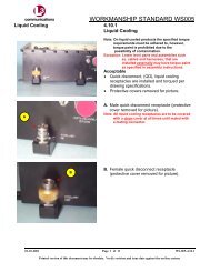
The <strong>9040</strong>-T(A) is housed in a standard<br />
19” wide EIA housing. EMI/RFI integrity<br />
is assured by the design which includes<br />
gaskets, solid coaxial cables and a<br />
machined housing for critical<br />
sub-assemblies. The power line is isolated<br />
by multi-section EMI/RFI fi lters to further<br />
assure satisfactory performance in any<br />
environment.<br />
SPECIFICATIONS<br />
<strong>Model</strong> <strong>9040</strong>-T (A)<br />
Versatile Frequency Converter<br />
Number of Channels One<br />
Input Tuning Range (Variable) 10 kHz to 400 MHz<br />
(10 kHz to 120 MHz) Imageless Mixers<br />
Input Fixed Frequency .455/.85/1.7/6.8/8.83/10.7/13.6/21.4/27.2/70/140/160/300/<br />
400/1000 MHz<br />
Output Tuning Range (Variable) 10 kHz to 400 MHz<br />
(10 kHz to 120 MHz) Non-Imageless Mixers<br />
Output Fixed Frequency 3/6/10/15/20/21.4/25/30/40/50/70/140/160/300/400 MHz<br />
Tuning Resolution 1 kHz<br />
*NOTE: All common IF frequencies such as 455 kHz, 21.4 MHz, 10.7 MHz,<br />
70 MHz and 160 MHz can be selected on the input or the output as can any<br />
of the FDM group, super group or master group frequencies. Entire TDM<br />
bands or other signals with bandwidths up to 100 MHz can be processed.<br />
Incremental Tuning Step Size Programmable for any 1 kHz resolution increment.<br />
Selectable Bandwidths Up to thirteen bandwidths selectable bandwidths are available per<br />
unit -1/2/4/6/8/10/12/20/30/40/50/60/80 MHz and Bypass are provided<br />
in the standard <strong>9040</strong>-T(A).<br />
Input/Output Bandwidth +100/-97% of center frequency.<br />
(Imageless Mode) Not to exceed 100 MHz or the band edges of 10 kHz to 120 MHz<br />
Selectable Group Delay<br />
Equalizers Nine group Delay OUTPUT Equalizers of 3/6/10/15/20/25/30/40/50<br />
MHz center frequencies are provided in the standard <strong>9040</strong>-T(A).<br />
These group delay equalizers are in the output baseband section.<br />
Group Delay Variations Over ±75% of Output Center Frequency<br />
Output CF Group Delay<br />
3 MHz ± 35 nanoseconds<br />
6 MHz ± 16 nanoseconds<br />
10 MHz ± 10 nanoseconds<br />
15 MHz ± 8 nanoseconds<br />
20 MHz ± 5 nanoseconds<br />
25 MHz ± 4 nanoseconds<br />
30 MHz ± 3.1 nanoseconds<br />
40 MHz ± 4.2 nanoseconds<br />
50 MHz ± 5 nanoseconds<br />
*NOTE: The Group Delay specifi cations above are valid when unit is in the Output<br />
TDE Mode and with NO SAW Filters or Imageless upconverters selected.<br />
Anti-aliasing In the time-delay equalizer mode, anti-aliasing is available from both<br />
the band pass fi lters and from a multi-section eliptical function low<br />
pass fi lter that is an integral part of the time delay equalizer. When<br />
the time delay equalizers are not in use, the anti-aliasing is derived<br />
from the bandpass fi lters.<br />
Amplitude Variation Less than ±1.5 dB over 75% Bandwidth for 3/6/10/15/20 MHz C.F.<br />
Less than ±2 dB over 75% Bandwidth for 25/30/40 MHz C.F.<br />
Less than ±2.2 dB over 75% Bandwidth for 50 MHz C.F.<br />
Input Level (IF Frequencies) -56 dBm to +4 dBm<br />
Output Level -30 dBm to +4 dBm<br />
MGC Range 60 dB Minimum<br />
AGC Range 60 dB Minimum<br />
AGC Output Stability Less than ±1.0 dB output level change over the specifi ed input<br />
signal range
SPECIFICATIONS<br />
<strong>Model</strong> <strong>9040</strong>-T (A)<br />
Versatile Frequency Converter<br />
Image Rejection/Undesired<br />
Mixer Product Rejection Employs imageless mixers and SAW fi lters yielding rejection performance that is confi guration dependent. Typical measured<br />
rejection is 35 dB from the imageless mixers and at least 40 dB from the SAW Filters giving a total 75 dB rejection outside the<br />
40 dB IF shape factors listed below.<br />
Typical Filter Performance<br />
BW 3 dB BW 3 dB BW 1 dB BW 40 dB GD VAR<br />
Min (MHz) Typ (MHz) Min (MHz) Max (MHz) ± nsec<br />
*Measured at 30 dB Bandwidth<br />
Frequency Stability Internal ± 25 ppm<br />
1 1.04 0.77 2.2 50<br />
2 2.071 1.65 3.9 23<br />
4 4.217 3.7 6.0 23<br />
6 6.3 5.6 8.4 25<br />
8 8.18 7.3 10.6 36<br />
10 10.35 9.3 13.0 30<br />
12 12.2 11.1 15.0 18<br />
20 20.4 18.8 25.0 10<br />
30 32.2 29.7 40.0 8<br />
40 40.1 37.0 50.0 6<br />
50 56.5 47.5 73.0 5<br />
60 64.7 60.0 81.0 5<br />
80 81.7 64.0 113.0* 6<br />
Phase Noise Less than 2 degrees RMS for 0.5 to 20 kHz Offset<br />
Impedance - All Signal Ports 50 ohms<br />
VSWR Input 1.5:1<br />
Output 2.0:1<br />
Total Harmonic Distortion Less than 2% with tone 6 dB below nominal output level<br />
Two-tone Intermodulation<br />
Products Greater than -40 dBc with each tone 6 dB below nominal output level<br />
Spurious Output 50 dB down<br />
LO Rejection 50 dB down typical when input CF is ≥ 40 dB BW ÷ 2 (Input Alert Light OFF)<br />
External Reference Frequency Input Frequency 10 MHz<br />
Input Level 0.5 Vms to 5.0 Vms<br />
Input Impedenance 50 Ohms<br />
VSWR 2.0:1<br />
Connectors Signal Port connectors (all) BNC<br />
External Reference Connector BNC<br />
Control Connector IEEE-488 Standard (metal shell)<br />
Controls: Local/Remote (1) Input Frequency (Tunable and Fixed Random Access)<br />
(2) Output Frequency (Tunable and Fixed Random Access)<br />
(3) Incremental Frequency Selection via UP/Down Arrow Keys<br />
(4) Bandwidth and Bypass<br />
(5) Imageless Mode<br />
(6) AGC/MGC<br />
(7) Input/Output Attenuation<br />
(8) Local/Remote Operation<br />
(9) Local Lockout*<br />
(10) Explicit Time Delay Equalizer Selection (Remote Only)<br />
(11) AC Power<br />
*Local lockout can be disabled from a rear panel switch that will ignore a local lockout from a remote user. If the local lockout function is disabled from the rear<br />
panel, pressing the local selection switch will ALWAYS cause the unit to return to local operation.
SPECIFICATIONS<br />
<strong>Model</strong> <strong>9040</strong>-T (A)<br />
Versatile Frequency Converter<br />
Indicators (Red LED) (1) Input Center Frequency Display<br />
(2) Output Center Frequency Display<br />
(3) “Alert” Indicator to indicate excessive Bandwidth selection<br />
(4) Selected Bandwidth Display<br />
(5) AGC/MGC<br />
(6) LOCAL/REMOTE/LOCKOUT<br />
(7) Incremental Tuning Steps<br />
(8) EXTERNAL REFERENCE IN USE<br />
(9) LO UNLOCK<br />
(10) Input Attenuation level in MGC Mode<br />
(11) Input overload<br />
(12) AGC level is displayed on a 20-segment front panel bargraph when in AGC mode. The level driving this meter is<br />
converted and made available to the IEEE-488 bus. In the MGC mode, this meter indicates the relative level of<br />
input attenuation.<br />
(13) Output Attenuation is displayed on two 7-segment displays. The information is also available over the IEEE-488<br />
bus.<br />
(14) Imageless<br />
(15) Tuning Knob Disable<br />
(16) Power On<br />
Dimensions 7.0” x 19” x 22” (HWD)<br />
Weight 55 lbs. (approximate)<br />
NOTES:<br />
1. Subsequent to loss of power, converter returns to Local control mode and restores all settings that were in effect at the time of power failure.<br />
2. Under Remote control mode of operation, all local control functions are disabled except AC power switch and local selection switch<br />
Environmental Storage Temperature 0° to +50° C<br />
Relative Humidity 0 to 95% non-condensing<br />
Environmental Operating Temperature 0° to +50° C<br />
Relative Humidity 0 to 95% non-condensing<br />
Power 90-264 VAC, Autoranging<br />
47-440 Hz<br />
150 Watts<br />
For Additional Information Contact:<br />
L-3 Communication Systems-East<br />
One Federal Street, Camden, NJ 08103<br />
Telephone: 856-338-INFO<br />
Fax: 856-338-2550<br />
E-mail: logen.thiran@L-3Com.com<br />
or Visit our Website at:<br />
http://www.L-3Com.com/COMINT<br />
Cleared by DoD/DFOISR for Public Release under DFOISR case number 04-S-0865 on March 18, 2004<br />
All Data and Specifi cations Subject to Change<br />
COM<strong>9040</strong>TA-01/04