Zielgruppe - CEAG
Zielgruppe - CEAG
Zielgruppe - CEAG

You also want an ePaper? Increase the reach of your titles
YUMPU automatically turns print PDFs into web optimized ePapers that Google loves.
Betriebsanleitung<br />
Betriebsanleitung<br />
DLS/3PH-BUS-Modul<br />
<strong>Zielgruppe</strong>: Elektrofachkräfte<br />
Operating instructions<br />
DLS/3PH-BUS-Module<br />
Target group: Skilled electricians<br />
300 80 001 642 (A)
2<br />
Sicherheitshinweise<br />
Sicherheitshinweise<br />
� Das elektronische Überwachungsgerät<br />
DLS/3PH-<br />
BUS-Modul ist bestimmungsgemäß<br />
in unbeschädigtem<br />
und einwandfreiem<br />
Zustand zu betreiben!<br />
� Bei Durchführung von Arbeiten<br />
am Gerät ist sicherzustellen,<br />
dass das Gerät<br />
spannungsfrei geschaltet<br />
ist! Beachten Sie dabei die<br />
unterschiedlichen Versorgungen<br />
des Geräts bei<br />
Normal- und Notbetrieb.<br />
� Beachten Sie bei allen Arbeiten<br />
an dem Gerät die<br />
nationalen Sicherheits- und<br />
Unfallverhütungsvorschriften<br />
und die nachfolgenden<br />
Sicherheitshinweise in der<br />
Betriebsanleitung, die mit<br />
einem versehen sind!<br />
Normenkonformität<br />
Normenkonformität<br />
Konform mit: EMV-Richtlinie 89/<br />
336/EWG, Niederspannungsrichtlinie<br />
73/236/EWG,<br />
EN 50081-1, EN 61000-6-2,<br />
EN 50178, Schaltschwellen<br />
gem. EN 60598-2-22,<br />
EN 50171 und VDE 0108.<br />
Gemäß DIN EN ISO 9001 entwickelt,<br />
gefertigt und geprüft.<br />
Technische Daten<br />
Versorgungsspannung<br />
Gerät: 24 V DC<br />
(min. 19 V,<br />
max. 30 V)<br />
Stromaufnahme (alle 8 Kanäle<br />
angeschlossen):20 mA ± 5 mA<br />
Schutzart: IP 20<br />
Schutzklasse: I<br />
Umgebungstemperatur:<br />
-10 °C .. +40 °C<br />
Eingangskanäle: 8 (potential getrennt<br />
U N = 230 V)<br />
DLS (Kan. 1-8): > 195 V -> ON<br />
< 138 V -> OFF<br />
3PH (Kan. 6-8): > 195 V -> ON<br />
< 138 V -> OFF<br />
Datenbus: RS 485<br />
Adressbereich: 1 - 25<br />
Gewicht: 0,2 kg<br />
Abmessungen<br />
L x B x H/mm: 105 x 85 x 60<br />
Montage: DIN-Schiene<br />
Anschlussklemmen:<br />
2,5 mm² starr<br />
und flexibel<br />
Beschreibung/<br />
Verwendungsbereich<br />
Das elektronische Überwachungsmodul<br />
dient als<br />
Lichtschalterabfrage, wodurch<br />
Leuchten der Allgemeinbeleuchtung<br />
und Leuchten der<br />
Sicherheitsbeleuchtung im<br />
Netzbetrieb gemeinsam geschaltet<br />
werden können, sowie<br />
als 3-Phasenüberwachung in<br />
Verbindung mit <strong>CEAG</strong><br />
Sicherheitsbeleuchtungsanlagen<br />
Typ ZB-S.<br />
Installation<br />
Installation<br />
Halten Sie die für das Errichten<br />
und Betreiben von elektrischen<br />
Betriebsmitteln geltenden Sicherheitsvorschriften,<br />
das Gerätesicherheitsgesetz<br />
sowie die allgemein<br />
anerkannten Regeln der<br />
Technik ein!<br />
Montage<br />
Der Einbauort ist gemäß der<br />
einschlägigen Errichtungsnormen<br />
zu wählen (z.B. Unterverteilungen).<br />
Hierbei ist auf unzulässige<br />
Temperaturen am Einbauort<br />
während des Betriebs<br />
zu achten.<br />
Funktionsweise<br />
Das DLS /3PH Bus-Modul hat<br />
8 getrennte Eingangskanäle<br />
zum Abfragen von 230 V AC<br />
Netzspannungen. Zugehörige<br />
gelben LED in der Frontplatte<br />
zeigen den Schaltzustand an.<br />
Mit dem Schiebeschalter in der<br />
Frontplatte kann das Modul<br />
von DLS (Dauer Licht Schalterabfrage)<br />
in 3PH (Dreiphasenüberwachung)<br />
umgeschaltet<br />
werden. In Stellung DLS sind<br />
alle 8 Eingangskanäle als DLS<br />
aktiv. In Stellung 3PH sind die<br />
Kanäle 1 - 5 als DLS und nur
L N L N L N L N L N L N L<br />
1 2 3 4 5<br />
DLS / 3PH - BUS - M odul<br />
400 71 346 955<br />
1 2 3 4 5 6 7 8<br />
EIN / ON<br />
St”rung / Failure<br />
6 7 8<br />
L1 L2 L3<br />
* * *<br />
* = 3PH<br />
DLS<br />
3 PH<br />
+ 24V - IN R S485 Out<br />
N L N PE PE<br />
2 3<br />
1<br />
0<br />
PE<br />
address<br />
1<br />
0<br />
2 3 4<br />
5<br />
9 6<br />
8 7<br />
X X X + + + - - - SE A B SE A B X B1 B2<br />
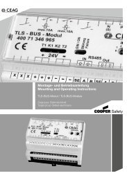
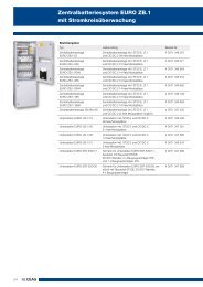
Servicetaster zur Überprüfung der Kommunikation Modul -<br />
Sicherheitsbeleuchtungsanlage über den RS 485-BUS<br />
Bild 1<br />
Anschlussbild DLS/3PH Modul<br />
1<br />
0<br />
address<br />
2 3<br />
1<br />
0<br />
2 3 4<br />
5<br />
9<br />
8 7<br />
6<br />
B B1 B2<br />
X<br />
Bild 2<br />
Adress- Adressschalter<br />
1 schalter 2<br />
Adressschalter 1 Adressschalter 2 Moduladresse<br />
0 0 nicht zulässig<br />
0 1 1<br />
0 2 2<br />
... ... ...<br />
1 0 10<br />
1 1 11<br />
... ... ...<br />
... ... ...<br />
2 5 25<br />
2 6 nicht zulässig<br />
... ... ...<br />
3 9 nicht zulässig<br />
die Eingangskanäle 6 (L1); 7<br />
(L2); 8 (L3) als 3-Phasenüberwachung<br />
aktiv. Die RS<br />
485 Schnittstelle sowie die<br />
Spannungsversorgung 24 V<br />
DC wird von der <strong>CEAG</strong>-<br />
Sicherheitsbeleuchtungsanlage<br />
versorgt. Der 230 V-Schaltbefehl<br />
an den Eingängen 1-8<br />
wird an die <strong>CEAG</strong>-Notlichtanlage<br />
über den BUS weitergeleitet.<br />
Die an der Notlichtanlage<br />
angeschlossenen Sicherheitsleuchten<br />
werden entsprechend<br />
ihrer Programmierung ein- oder<br />
ausgeschaltet.<br />
Die grüne LED in der Frontplatte<br />
signalisiert störungsfreien<br />
Betrieb, die rote LED zeigt eine<br />
Störung an.<br />
Werden mehrere Module (max.<br />
25 Stück) an einer Notlichtanlage<br />
betrieben, so ist der RS<br />
485 Bus wie auch die 24 V<br />
Versorgung hintereinander zu<br />
schalten. Der Schirm der Busleitung<br />
ist mit geeigneter<br />
Klemmvorrichtung an der<br />
Klemme SE anzuschließen.<br />
Am Anfang und am Ende der<br />
BUS-Leitung ist jeweils ein<br />
Abschlusswiederstand (120 Ω)<br />
zu installieren. Hierfür sind im<br />
jeweils letzten Modul die Klemmen<br />
B1/B2 mit einer Brücke zu<br />
versehen, die den eingebauten<br />
Abschlusswiderstand aktiviert.<br />
Ist die Sicherheitsanlage Anfang<br />
der Busleitung, so ist an<br />
den hierfür vorgesehenen<br />
Klemmen der entsprechende<br />
Abschlusswiderstand zu installieren.<br />
Adressierung<br />
Vor Betrieb an einer <strong>CEAG</strong>-<br />
Sicherheitsbeleuchtungsanlage<br />
muss die Moduladressierung<br />
vorgenommen werden. Hierzu<br />
ist mit einem geeigneten<br />
Schraubendreher die gewünschte<br />
Adresse (1 - 25) an<br />
den zwei Codierschaltern in<br />
der Frontplatte des Moduls<br />
einzustellen (Pfeil auf Zahl,<br />
Bild 2).<br />
.<br />
3
Bild 3: Schaltung eines DLS/3PH BUS-Moduls<br />
Abschluss- *<br />
widerstand<br />
120 Ω<br />
TLS<br />
DLS<br />
RS485-BUS<br />
ZB-S<br />
TLS<br />
max. 1200 m bei J-Y(ST)Y 4 x 2 x 0,8 mm<br />
DLS<br />
nächstes<br />
Modul<br />
* Abschlusswiderstand<br />
120 Ω<br />
Bild 4.<br />
Busstruktur RS485-BUS<br />
� Double Terminated Bus Topologie/Linienstruktur<br />
� max. 25 Module (DLS/TLS)<br />
� Querschnitt für 24 V-Versorgung ist gemäß Anzahl der Module sowie Leitungslänge zu<br />
berechnen. U für Modul = 19 V<br />
min<br />
� Empfohlene Leitung: JY(ST)Y 4 x 2 x 0,8 mm, Twisted Pair (verdrillte Zweidraht-Leitung) ,<br />
geschirmt<br />
� Keine Stichleitungen zulässig!<br />
* * * Im DLS/3Ph-Bus-Modul ist der 120 Ohm-Abschlußwiderstand integriert<br />
und kann durch eine Brücke an den Klemmen B1/B2 aktiviert werden.<br />
4<br />
Bitte lesen Sie dazu auch Seite 3.
Safety Instructions<br />
�The electronic monitoring<br />
module shall only be used<br />
for its intended purpose<br />
and in undamaged and<br />
perfect condition!<br />
� When working on the<br />
electronic device make sure<br />
that it is disconnected from<br />
the voltage! Pay attention to<br />
the different power supplies<br />
in mains or battery operation.<br />
�Observe the national safety<br />
rules and regulations for<br />
prevention of accidents as<br />
well as the safety instructions<br />
included in these<br />
operating instruction<br />
marked with<br />
Conformity with<br />
standards<br />
Conforming to: EMC-directive<br />
89/336/EWG, Low Voltage<br />
Directive 73/236/EWG,<br />
EN 50081-1, EN 61000-6-2,<br />
EN 50178, Switching point<br />
accd. EN 60598-2-22,<br />
EN 50171 and VDE 0108.<br />
Developed, manufactured and<br />
tested acc. to ISO 9001.<br />
Technical data<br />
Voltage supply<br />
module: 24 V DC<br />
(min. 19 V,<br />
max. 30 V)<br />
current consumption (all 8 channels<br />
connected): 20 mA ± 5 mA<br />
Degree of<br />
protection: IP 20<br />
Insulation class: I<br />
Perm. ambient<br />
temperature: -10 °C .. +40 °C<br />
Input channels: 8 (floating<br />
U N = 230 V)<br />
DLS (Chan. 1-8):> 195 V -> ON<br />
< 138 V -> OFF<br />
3PH (Chan. 6-8):> 195 V -> ON<br />
< 138 V -> OFF<br />
Data bus: RS 485<br />
Address range: 1 - 25<br />
Weight: 0.2 kg<br />
Dimensions<br />
L x W x H/mm: 105 x 85 x 60<br />
Assembly: DIN-Rail<br />
Terminals: 2.5 mm² rigid<br />
and flexible<br />
Description/Scope of<br />
application<br />
The electronic monitoring<br />
module is used for light<br />
switch monitoring, in this<br />
way the general lighting and<br />
luminaires for the safety lighting<br />
can be switched together during<br />
mains operation. The module<br />
is also used for 3-phase<br />
monitoring in conjunction with<br />
<strong>CEAG</strong> safety lighting systems<br />
of type ZB-S.<br />
Installation<br />
For the mounting and<br />
operation of electrical<br />
apparatus, the respective<br />
national safety regulations<br />
as well as the general rules of<br />
engineering will have to be<br />
observed.<br />
Assembly<br />
The installation location is to be<br />
chosen in accordance with the<br />
applicable construction standards<br />
(e.g. subdistribution<br />
boards). During this process<br />
attention is to be paid to temperatures<br />
outside the permitted<br />
range at the installation location<br />
during operation.<br />
Principle of operation<br />
The DLS /3PH bus module has<br />
8 separate input channels for<br />
monitoring 230 V AC mains<br />
voltages. Associated yellow<br />
LEDs on the front panel indicate<br />
the switch state. Using the<br />
slider switch on the front panel,<br />
the module can be switched<br />
from DLS (maintained light<br />
switch monitoring) to 3PH<br />
(three phase monitoring). In the<br />
DLS position all 8 input<br />
5
1 2 3 4 5<br />
DLS / 3PH - BUS - M odul<br />
400 71 346 955<br />
6<br />
L N L N L N L N L N L N L<br />
1 2 3 4 5 6 7 8<br />
EIN / ON<br />
St”rung / Failure<br />
6 7 8<br />
L1 L2 L3<br />
* * *<br />
* = 3PH<br />
DLS<br />
3 PH<br />
+ 24V - IN R S485 Out<br />
N L N PE PE<br />
2 3<br />
1<br />
0<br />
PE<br />
address<br />
1<br />
0<br />
2 3 4<br />
5<br />
9 6<br />
8 7<br />
X X X + + + - - - SE A B SE A B X B1 B2<br />
Service key for testing of the communication between module -<br />
safety lighting via RS 485-BUS<br />
fig 1<br />
Connections DLS/3PH Modul<br />
1<br />
0<br />
address<br />
2 3<br />
1<br />
0<br />
2 3 4<br />
5<br />
9<br />
8 7<br />
6<br />
B B1 B2<br />
X<br />
fig. 2<br />
Address- Addressswitch<br />
1 switch 2<br />
Address swtch 1 Address switch 2 Module addresse<br />
0 0 not permissible<br />
0 1 1<br />
0 2 2<br />
... ... ...<br />
1 0 10<br />
1 1 11<br />
... ... ...<br />
... ... ...<br />
2 5 25<br />
2 6 not permissible<br />
... ... ...<br />
3 9 not permissible<br />
channels are active for DLS<br />
(maintained light switch monitoring).<br />
In the 3PH position,<br />
channels 1 - 5 are active for<br />
DLS (maintained light switch<br />
monitoring) and only the input<br />
channels 6 (L1); 7 (L2); 8 (L3)<br />
are active for 3 phase monitoring.<br />
The RS 485 interface as<br />
well as the 24 V DC power<br />
supply are supplied from the<br />
<strong>CEAG</strong>-safety lighting system.<br />
The 230 V switching command<br />
at the inputs 1-8 is forwarded<br />
to the <strong>CEAG</strong> emergency lighting<br />
system over the BUS. The<br />
safety luminaires connected to<br />
the emergency lighting system<br />
are switched on and off as per<br />
the programming.<br />
The green LED on the front<br />
panel indicated malfunctionfree<br />
operation; the red LED indicates<br />
a malfunction. If several<br />
modules (max. 25) are operated<br />
in an emergency lighting<br />
system, the RS 485 bus and<br />
the 24 V supply are to be connected<br />
in series. The screen<br />
on the bus cable is to be connected<br />
to the SE terminal using<br />
a suitable clamping arrangement.<br />
A terminating resistor (120 Ω)<br />
must be fitted at the start and<br />
end of the BUS cable. For this<br />
purpose, a jumper is to be fitted<br />
to terminals B1/B2 on the<br />
last module; this activates the<br />
built-in terminating resistor. If<br />
the safety system is at the start<br />
of the bus cable, then the appropriate<br />
terminating resistor is<br />
to be fitted to terminals provided<br />
for this purpose.<br />
Addressing<br />
Prior to operation in a <strong>CEAG</strong><br />
safety lighting system, the<br />
module address must be set.<br />
For this purpose the required<br />
address (1 - 25) is to be set on<br />
the code switches on the module<br />
front panel using a suitable<br />
screwdriver (arrow to number,<br />
Figure 2).
General lighting<br />
Safety lighting<br />
fig. 3: Wiring of the DLS/3PH BUS-Module<br />
Terminating *<br />
resistor<br />
120 Ω<br />
TLS<br />
DLS<br />
RS485-BUS<br />
ZB-S<br />
TLS<br />
max. 1200 m with J-Y(ST)Y 4 x 2 x 0.8 mm<br />
DLS<br />
next Module<br />
*Terminating<br />
resistor<br />
120 Ω<br />
fig.4<br />
Bus-structure RS485-BUS<br />
� Double terminated bus topology/Line structure<br />
� max. 25 modules (DLS/TLS)<br />
� Cross section for 24 V supply must be calculated according the number of modules as well<br />
as line length. U for module = 19 V<br />
min<br />
� recommend cable: JY(ST)Y 4 x 2 x 0.8 mm, twisted pair, shielded<br />
� No dead-end lines allowed.<br />
*In DLS/3Ph-Bus-module the 120 ohms terminating resistor is integrated<br />
and can be activate through a wire fitted to terminals B1/B2.<br />
Please read back page 6.<br />
7
<strong>CEAG</strong> Notlichtsysteme GmbH<br />
Senator-Schwartz-Ring 26<br />
D-59494 Soest / Germany<br />
Telefon + 49 29 21/69-870<br />
Telefax + 49 29 21/69-617<br />
Internet http://www.ceag.de<br />
E-mail info-n@ceag.de<br />
300 80 001 642(A)/ X / 10.03/ WE