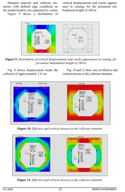
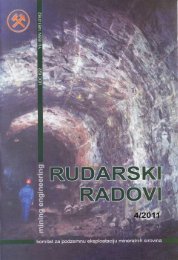
Dumped material and collector elements, with defined edge conditions on the model borders, are separated by colour Figure 9 shows a distribution of vertical displacements and cracks appearance in coating, for the presumed embankment height of 100 m. Figure 9. Distribution of vertical displacements and cracks appearance in coating, for presumed embankment height of 100 m Fig. 9 shows displacement inside the collector of approximately 1.0 cm. Fig. 10 and 11 show size of effective and vertical stresses in the collector elements. Figure 10. Effective and vertical stresses in the collector elements Figure 11. Effective and vertical stresses in the collector elements No 1,2010. 35 MINING ENGINEERING
Model of embankment material and basic soil were analyzed by the Mohr – Coulomb fracture condition, and model of collector material as the concrete material with the following characteristics: MB40, E = 24·10 5 kN/m 2 and the Poisson coefficient ν = 0.15 Size of collector relative subsidence is 18 [cm], while maximum collector depression is 35 cm. CONCLUSION Since the collector is the capital facility for a mine, particular attention should be paid to its development and environment of collector location (due to the stress-deformation condition). It is necessary to set up the stable benchmarks near inlet and outlet of the collector before taking any rehabilitation measures, and those benchmarks would be connected to the State trigonometric network and had the absolute elevations. With this absolute elevation, zero measurement of roof and floor should be made with precision levelling as the condition of these two points could be observed. All measurements and observations made on the collector under the open pit "Bogutovo selo“ in Ugljevik can be applied to the Kriveljska river tunnel. REERENCES [1] Study on the Results of Collector Auscultation Under the Open Pit “Bogutovo selo” in Ugljevik (in Serbian) [2] M. Ljubojev, M. Avdić, D. Ignjatović, L. Dj. Ignjatović, The Effect of Flotation Tailing Dump Field 2 on the Stability of the Kriveljska River Tunnel, Mining Engineering, 2/2009, pgs. 21 – 28, <strong>Bor</strong> 2009 (in Serbian) [3] M. Ljubojev, R. Popović, Basics of Geomechanics, RTB <strong>Bor</strong>, Copper <strong>Institut</strong>e <strong>Bor</strong>, 2006 (in Serbian) [4] M. Ljubojev, D. Ignjatović, L. Dj. Ignjatović, S. Krstić, Z. Stojanović, Evaluation of the Rock Stability of the Kriveljska River Tunnel Formed by Comparison of Classification the Rock Strength, Journal COPPER, No. 1, 2009, Vol. 34, pgs. 9-14 (in Serbian) [5] M. Ljubojev, Z. Stojanović, D. Mitić, D. Ignjatović, The Proposal of Method for Construction the New Tunnel of the Kriveljska River, Innovation and Development, No. 1, 2009, pgs. 51-60 (in Serbian) [6] M. Ljubojev, M. Avdić, M. Bugarin, R. Popović, D. Ignjatović, Tunnel Analysis in the Fault Zones and the Effects of Stress distribution on the Support, 2009, Journal of Mining and Metallurgy, Vol. 45, No. 1, pgs. 49-57. No 1,2010. 36 MINING ENGINEERING
- Page 2 and 3: INSTITUT ZA RUDARSTVO I METALURGIJU
- Page 4 and 5: KOMITET ZA PODZEMNU EKSPLOATACIJU Y
- Page 6 and 7: Analizirajući ovaj način uzorkova
- Page 8 and 9: SADRŽINA UPROŠĆENOG RUDARSKOG PR
- Page 10 and 11: COMMITTEE OF UNDERGROUND EXPLOITATI
- Page 12 and 13: area is constantly increased. Figur
- Page 14 and 15: CONTENT OF THE SIMPLIFIED MINING PR
- Page 16 and 17: KOMITET ZA PODZEMNU EKSPLOATACIJU Y
- Page 18 and 19: U morfološkom smislu, teren predst
- Page 20 and 21: Rezultati terenski istraživanja i
- Page 22 and 23: COMMITTEE OF UNDERGROUND EXPLOITATI
- Page 24 and 25: In morphological terms, the terrain
- Page 26 and 27: GEO-MECHANICAL FEATURES OF THE TERR
- Page 28 and 29: KOMITET ZA PODZEMNU EKSPLOATACIJU Y
- Page 30 and 31: Sl. 3. Smičući naponi u konstrukc
- Page 32 and 33: Na modelu bojom su razgraničeni od
- Page 34 and 35: COMMITTEE OF UNDERGROUND EXPLOITATI
- Page 36 and 37: Figure 3. Shear stresses in collect
- Page 40 and 41: KOMITET ZA PODZEMNU EKSPLOATACIJU Y
- Page 42 and 43: PODRUČJE ISTRAŽIVANJA Aleksinačk
- Page 44 and 45: Da bi se izbor otkopne mehanizacije
- Page 46 and 47: lansnih rezervi uglja, a druga za g
- Page 48 and 49: veličina i takođe zahteva neophod
- Page 50 and 51: COMMITTEE OF UNDERGROUND EXPLOITATI
- Page 52 and 53: exploitation, two variants of this
- Page 54 and 55: esses, require the use of modern sy
- Page 56 and 57: • method without underground room
- Page 58 and 59: directly used to drive power plants
- Page 60 and 61: KOMITET ZA PODZEMNU EKSPLOATACIJU Y
- Page 62 and 63: gde je: Δ - nasipna masa uzorka; m
- Page 64 and 65: D (%) 100 90 80 70 60 50 40 30 20 1
- Page 66 and 67: COMMITTEE OF UNDERGROUND EXPLOITATI
- Page 68 and 69: Where is: Δ - volumetric density o
- Page 70 and 71: D (%) 100 90 80 70 60 50 40 30 20 1
- Page 72 and 73: KOMITET ZA PODZEMNU EKSPLOATACIJU Y
- Page 74 and 75: PRORAČUN STABILNOSTI SOFTVEROM GEO
- Page 76 and 77: Sl. 6. Izgled klizne ravni i koefic
- Page 78 and 79: COMMITTEE OF UNDERGROUND EXPLOITATI
- Page 80 and 81: CALCULATION OF STABILITY BY THE SOF
- Page 82 and 83: Figure 6. View of sliding plane and
- Page 84 and 85: KOMITET ZA PODZEMNU EKSPLOATACIJU Y
- Page 86 and 87: kon sulfatizacije, postignut je sle
- Page 88 and 89:
COMMITTEE OF UNDERGROUND EXPLOITATI
- Page 90 and 91:
Table 2. Degrees of metal leaching
- Page 92 and 93:
KOMITET ZA PODZEMNU EKSPLOATACIJU Y
- Page 94 and 95:
70%. Dreniranje izdani vrši se po
- Page 96 and 97:
do kote K+656 m gde su postavljene
- Page 98 and 99:
COMMITTEE OF UNDERGROUND EXPLOITATI
- Page 100 and 101:
is very abundant feeding aquifers.
- Page 102 and 103:
Start-minute maximum intensity of d
- Page 104 and 105:
Figure 3. Operation diagram of pump
- Page 106 and 107:
KOMITET ZA PODZEMNU EKSPLOATACIJU Y
- Page 108 and 109:
Zlato u koncentratu kg - 27,988 12,
- Page 110 and 111:
Na samlevenim uzorcima topioničke
- Page 112 and 113:
COMMITTEE OF UNDERGROUND EXPLOITATI
- Page 114 and 115:
Dry concentrate t 5,226 10.563 5.82
- Page 116 and 117:
Sadržaj klase -75μm , % 100 80 60
- Page 118 and 119:
KOMITET ZA PODZEMNU EKSPLOATACIJU Y
- Page 120 and 121:
Tab. 1. Koordinate temena eksploata
- Page 122 and 123:
Eksploatacija ležišta rude bakra
- Page 124 and 125:
COMMITTEE OF UNDERGROUND EXPLOITATI
- Page 126 and 127:
Figure 3. Mutual position of open p
- Page 128 and 129:
underground water in the first wate
- Page 130 and 131:
KOMITET ZA PODZEMNU EKSPLOATACIJU Y
- Page 132 and 133:
gde su: v r - brzina protoka: u r -
- Page 134 and 135:
COMMITTEE OF UNDERGROUND EXPLOITATI
- Page 136 and 137:
z and r - cylindrical coordinates
- Page 138 and 139:
KOMITET ZA PODZEMNU EKSPLOATACIJU Y
- Page 140 and 141:
da zaštiti podzemne vode od kontam
- Page 142 and 143:
• Otpadne vode od samog postrojen
- Page 144 and 145:
COMMITTEE OF UNDERGROUND EXPLOITATI
- Page 146 and 147:
Practically, the “in-situ” expl
- Page 148 and 149:
• Waste water created during the
- Page 150 and 151:
KOMITET ZA PODZEMNU EKSPLOATACIJU Y
- Page 152 and 153:
geotektonska zona prema severoistok
- Page 154 and 155:
Osmatrani režim izdašnosti i temp
- Page 156 and 157:
Sl. 4. Kružni dijagram hemijskog s
- Page 158 and 159:
15. Nikl (Ni) 0,012±0,00500 UP-919
- Page 160 and 161:
alneoterapijskih i sportsko-rekreat
- Page 162 and 163:
COMMITTEE OF UNDERGROUND EXPLOITATI
- Page 164 and 165:
phase are presented by andesite bas
- Page 166 and 167:
Figure 1. Hydro-geology maps of the
- Page 168 and 169:
Spring 2 Figure 3. Circle diagram o
- Page 170 and 171:
12. Lead (Pb)
- Page 172 and 173:
ecreational activities. The beginni
- Page 174 and 175:
UTICAJ GRANULOMETRIJSKOG SASTAVA ML
- Page 176 and 177:
SADR@AJ CONTENS D. Sokolović, D. E