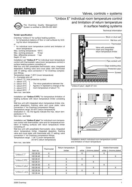
Valves, controls + systems “Unibox E” individual room ... - Oventrop
Valves, controls + systems “Unibox E” individual room ... - Oventrop
Valves, controls + systems “Unibox E” individual room ... - Oventrop

Create successful ePaper yourself
Turn your PDF publications into a flip-book with our unique Google optimized e-Paper software.
Tender specification:<br />
<strong>Oventrop</strong> <strong>“Unibox</strong> <strong>E”</strong> for surface heating <strong>systems</strong><br />
– for temperature balance of floor or wall surfaces by limiting<br />
the return temperature<br />
or<br />
– for <strong>individual</strong> <strong>room</strong> temperature control and limitation of<br />
return temperature<br />
Max. working temperature: 100°C<br />
Max. working pressure: 10 bar<br />
Max. differential pressure: 1 bar<br />
Depth: 57 mm<br />
Installation set <strong>“Unibox</strong> E T” for <strong>individual</strong> <strong>room</strong> temperature<br />
control with thermostatic valve (<strong>room</strong> temperature control) in<br />
surface heating <strong>systems</strong> consisting of:<br />
Wall box unit with presettable thermostatic valve, integrated<br />
deaeration, flushing valve and cover plate; with thermostat<br />
with ‘0’ setting; valve connection 3 ⁄4” for <strong>Oventrop</strong> compression<br />
fittings.<br />
Temperature range: 7-28°C (<strong>room</strong> temperature)<br />
0 = Complete shut off<br />
* = about 7°C, frost protection symbol<br />
1 = about 12°C<br />
}<br />
2 = about 16°C<br />
3 = about 20°C<br />
4 = about 24°C<br />
5 = about 28°C<br />
Item nos.: see table<br />
Installation set <strong>“Unibox</strong> E RTL” for temperature limitation of<br />
heating surfaces with return temperature limiter consisting<br />
of:<br />
Wall box unit with integrated return temperature limiter, integrated<br />
deaeration, flushing valve and cover plate; valve<br />
connection 3 ⁄4” for <strong>Oventrop</strong> compression fittings.<br />
Temperature range: 20-40°C (return temperature)<br />
Graduation 0 – 40; the figures indicate the max. return temperatures<br />
in °C.<br />
Item nos.: see table<br />
Installation set <strong>“Unibox</strong> E plus” for <strong>individual</strong> <strong>room</strong> temperature<br />
control with thermostatic valve and for temperature limitation<br />
of heating surfaces with return temperature limiter<br />
consisting of:<br />
Wall box unit with presettable thermostatic valve, integrated<br />
return temperature limiter, integrated dearation, flushing<br />
valve and cover plate; with thermostat with ‘0’ setting; valve<br />
connection 3 ⁄4” for <strong>Oventrop</strong> compression fittings.<br />
Temperature range: 7-28 °C (<strong>room</strong> temperature)<br />
20-40°C (return temperature)<br />
Item nos.: see table<br />
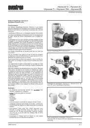
<strong>“Unibox</strong> E T”<br />
<strong>“Unibox</strong> E RTL”<br />
<strong>“Unibox</strong> E plus”<br />
<strong>“Unibox</strong> E vario”<br />
The <strong>Oventrop</strong> Quality Management<br />
System is certified to DIN-EN-ISO 9001<br />
The minor graduations between the<br />
figures 2-4 represent a change of the<br />
<strong>room</strong> temperature of about 1°C.<br />
<strong>Valves</strong>, <strong>controls</strong> + <strong>systems</strong><br />
<strong>“Unibox</strong> <strong>E”</strong> <strong>individual</strong> <strong>room</strong> temperature control<br />
and limitation of return temperature<br />
in surface heating <strong>systems</strong><br />
<strong>“Unibox</strong> E plus”, depth 57 mm<br />
Surface heating<br />
Technical information<br />
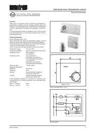
Block or stud wall<br />
Wal box unit<br />
Thermostat<br />
Valve with presettable<br />
insert and integrated<br />
return temperature limiter<br />
Plaster<br />
Pipe conduit unit<br />
Edge isolating strip<br />
Protection pipe<br />
Installation sketch <strong>individual</strong> <strong>room</strong> temperature control<br />
and limitation of return temperature<br />
Screed<br />
2006 <strong>Oventrop</strong> 1<br />
Supply<br />
Item no.<br />
Thermostat<br />
Return temperature<br />
limiter white<br />
Cover<br />
chrome plated<br />
Visible thermostat<br />
white chrome plated<br />
102 26 32 X X X<br />
102 26 42 X X X<br />
102 26 31 X X<br />
102 26 41 X X<br />
102 26 33 X X X X<br />
102 26 43 X X X X<br />
102 26 34 X X<br />
102 26 44 X X<br />
Return
Installation set <strong>“Unibox</strong> E vario” as basic model for temperature<br />
limitation of heating surfaces with return temperature<br />
limiter consisting of:<br />
Wall box unit with presettable thermostatic valve, integrated<br />
return temperature limiter, integrated deaeration, flushing<br />
valve and closed cover plate; valve connection 3 ⁄4” for <strong>Oventrop</strong><br />
compression fittings.<br />
Temperature range: 20-40°C (return temperature)<br />
Item nos.: see table<br />
For <strong>room</strong> temperature control, the following items have to be<br />
ordered separately:<br />
– Thermostat with remote control “Uni LH”<br />
(see catalogue “Products”, page 13.23)<br />
or<br />
– Room thermostat and actuator<br />
(see catalogue “Products”, pages 1.12, 1.13)<br />
Pipe conduit unit, depth 100 cm, completely insulated,<br />
includes fixing material:<br />
Item no. 102 26 50<br />
Compression fittings (see catalogue “Products”, page 1.45)<br />
Application:<br />
The different models of the <strong>“Unibox</strong>” are suitable for the<br />
operation of surface heating in a <strong>room</strong> with a heating surface<br />
up to 20 m 2 . They are designed for the connection of one<br />
heating circuit. Two circuits are required for larger heating<br />
surfaces. In this case, the pipes must be of the same length<br />
and have to be connected with the help of a T-piece or the<br />
“h” fitting, item no. 102 87 50 and the connection fitting, item<br />
no. 101 63 04 (see installation sketch on page 4) before entering<br />
the <strong>“Unibox</strong>”. The pressure loss can be reduced with the<br />
help of a larger sized return pipe. When installing heating<br />
pipes with an inner diameter of 12 mm, a pipe length of 100 m<br />
per heating circuit should not be exceeded. When laying the<br />
pipe, it is to be observed that the supply and the return pipe<br />
are alternately laid side by side. See e.g. spiral laying in the<br />
installation sketches. The examples of calculation mentioned<br />
below show some examples of laying.<br />
The <strong>“Unibox</strong> E RTL” allows the temperature limitation of<br />
heating surfaces. The <strong>room</strong> temperature is controlled via the<br />
radiators. Installation is carried out in combination with a<br />
radiator heating with a max. flow temperature of 70°C.<br />
The <strong>“Unibox</strong> E T” allows the control of the <strong>room</strong> temperature<br />
via the surface heating. It is used in combination with a low<br />
temperature heating installation with a max. flow temperature<br />
of 55°C.<br />
The <strong>“Unibox</strong> E plus” allows the <strong>individual</strong> <strong>room</strong> temperature<br />
control with a thermostatic valve and the temperature limitation<br />
of the heating surfaces with a return temperature limiter.<br />
As for the <strong>“Unibox</strong> E RTL”, installation is carried out in combination<br />
with a radiator heating with a max. flow temperature<br />
of 70°C.<br />
The <strong>“Unibox</strong> E vario” is used like a <strong>“Unibox</strong> E plus” when<br />
mounting a thermostat with remote control or a <strong>room</strong> thermostat<br />
and an actuator, and without these additions like a<br />
<strong>“Unibox</strong> E RTL”.<br />
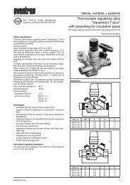
<strong>“Unibox</strong> E RTL”, depth 57 mm<br />
Block or stud wall<br />
Wall box unit<br />
Valve with integrated<br />
return temperature limiter<br />
2 2006 <strong>Oventrop</strong><br />
57<br />
8-23<br />
135<br />
60<br />
Supply<br />
Return<br />
Surface heating<br />
Installation sketch limitation of return temperature<br />
1000<br />
48<br />
155<br />
145<br />
135<br />
136 114<br />
8<br />
Dimensions <strong>“Unibox</strong> E RTL” and pipe conduit unit<br />
Plaster<br />
Pipe conduit unit<br />
Edge isolating strip<br />
Protection pipe<br />
155<br />
Screed
Function:<br />
The <strong>“Unibox</strong> E RTL” serves to limit the return temperature of<br />
surface heating. The <strong>“Unibox</strong> E RTL” should be installed in<br />
such a position that the heating medium passes through the<br />
heating circuit first and then through the valve. On its way<br />
from the entry into the heating surface to the return temperature<br />
limiter, the heating medium cools down.<br />
The flow is automatically controlled by a sensor element<br />
being in touch with the heating fluid. The return temperature<br />
is set at the handwheel. The guidelines regarding heating up<br />
and initial operation are to be observed.<br />
The temperature of the surface heating can be corrected by<br />
turning the handwheel.<br />
Normally, the <strong>“Unibox</strong> E RTL” is operated in a <strong>room</strong> with an<br />
additional radiator. The surface heating covers the basic heat<br />
demand whereas the radiator takes on the control of the<br />
<strong>room</strong> temperature.<br />
The <strong>“Unibox</strong> E T” may only be operated with a max. flow<br />
temperature of the surface heating of 55°C (low temperature<br />
heating). It offers a full <strong>individual</strong> <strong>room</strong> temperature control<br />
via the surface heating. It is recommended to install the <strong>“Unibox</strong><br />
E T” in such a position that the heating medium passes<br />
through the heating circuit first and then through the valve.<br />
This way, the automatic thermostat <strong>controls</strong> the desired<br />
<strong>room</strong> temperature exactly. The hydronic balancing is carried<br />
out at the presettable valve insert.<br />
The <strong>“Unibox</strong> E T” can be operated without an additional<br />
radiator provided that the heat output capacity of the surface<br />
heating is sufficient.<br />
The <strong>“Unibox</strong> E plus” serves to control the temperature of<br />
<strong>individual</strong> <strong>room</strong>s via the surface heating and to limit the temperature<br />
of the heating surface with the help of the return<br />
temperature limiter at the same time.<br />
The <strong>“Unibox</strong> E plus” is installed in the same position as the<br />
<strong>“Unibox</strong> E RTL”. The heating medium has to pass through<br />
the heating circuit of the surface heating first and then<br />
through the valve. On its way from the entry into the heating<br />
surface to the return temperature limiter, the heating medium<br />
cools down.<br />
The flow is automatically controlled by a sensor element<br />
being in touch with the heating fluid.<br />
The return temperature is set at the handwheel. The notes<br />
below regarding heating up and initial operation are to be observed.<br />
The surface temperature can be corrected by turning the<br />
handwheel.<br />
The automatic thermostat <strong>controls</strong> the desired <strong>room</strong> temperature.<br />
The hydronic balancing is carried out at the presettable<br />
valve insert. The <strong>“Unibox</strong> E plus” can be operated without an<br />
additional radiator, provided the heat output capacity of the<br />
surface heating is sufficient.<br />
The <strong>“Unibox</strong> E vario” offers the same function as the <strong>“Unibox</strong><br />
E plus” when mounting a thermostat with remote control<br />
or a <strong>room</strong> thermostat and an actuator. The return temperature<br />
is limited with the help of the integrated return temperature<br />
limiter.<br />
For use as a <strong>“Unibox</strong> E vario”, return temperature control has<br />
to be added. This can be done by choosing one of the<br />
following options (to be ordered separately):<br />
1. With <strong>room</strong> thermostat and electrothermal actuator<br />
The electrothermal actuator is mounted on the vertical connection<br />
inside the <strong>“Unibox</strong> E vario”.<br />
To lead the connecting cable towards the <strong>room</strong> thermostat,<br />
drill a hole (Ø about 8 mm) at the marked point (sticker) on<br />
the outer wall of the wall unit.<br />
Electrical connections, especially in humid locations, must<br />
be carried out in accordance with the local Electricity Regulations<br />
and Standards.<br />
Temperature range: 5-30°C (<strong>room</strong> temperature)<br />
20-40°C (return temperature)<br />
2. With thermostat with remote control “Uni LH”<br />
The control is mounted on the vertical valve connection<br />
inside the <strong>“Unibox</strong> E vario”.<br />
The capillary towards the <strong>room</strong> temperature sensor can be<br />
led downwards out of the <strong>“Unibox</strong> E vario”. Laying through<br />
an empty pipe is advantageous.<br />
Temperature range: 7-28°C (<strong>room</strong> temperature)<br />
20-40°C (return temperature)<br />
Without these additions, control corresponds to the <strong>“Unibox</strong><br />
E RTL”. Hydronic balance can additionally be carried out with<br />
the help of the presettable valve insert.<br />
Temperature range: 20-40°C (return temperature)<br />
<strong>“Unibox</strong> E T”, depth 57 mm<br />
Distributor/collector<br />
Supply<br />
Surface heating<br />
Installation sketch <strong>individual</strong> <strong>room</strong> temperature control<br />
2006 <strong>Oventrop</strong> 3<br />
Return<br />
57<br />
8-23<br />
190<br />
1000<br />
48<br />
60<br />
155<br />
145<br />
Block or stud wall<br />
Wall box unit<br />
Valve with<br />
presettable insert<br />
Thermostat<br />
Plaster<br />
Pipe conduit unit<br />
Edge isolating strop<br />
Protection pipe<br />
Screed<br />
Dimensions <strong>“Unibox</strong> E T”, <strong>“Unibox</strong> E plus”, <strong>“Unibox</strong> E vario”<br />
and pipe conduit unit<br />
1<br />
2<br />
3<br />
4<br />
0<br />
135<br />
136 114<br />
8<br />
5<br />
210
Installation and assembly:<br />
If the surface heating is installed as an underfloor heating,<br />
the lower edge of the <strong>“Unibox</strong> <strong>E”</strong> should be at least 20 cm<br />
above the finished floor, the front edge should be on a level<br />
with the finished wall. The thickness of plaster and tiles has<br />
to be observed. A comfortable operation is given if it is installed<br />
at the height of light switches.<br />
The thermostat should not be influenced by other heat<br />
sources.<br />
- Do not install near other heat sources, e.g. additional radiators.<br />
- Avoid direct sunlight to the thermostat.<br />
- Do not install at a location exposed to draught.<br />
The wall box unit is to be installed with the hole pointing<br />
downwards. Alignment and fixing are made by use of the enclosed<br />
elbows. They can be fixed at the side of the wall box<br />
unit in different positions.<br />
The wall box unit is sealed in the wall. The valve is protected<br />
by a cover made of corrugated cardboard.<br />
For a simple installation of the vertical pipework, place the<br />
pipe conduit unit, item no. 102 26 50, into the wall below the<br />
wall box unit, shorten if required. Later, the front of the pipe<br />
conduit unit will be under plaster.<br />
If required, lay an empty pipe for the cable between <strong>room</strong><br />
thermostat and actuator or respectively the capillary of the<br />
thermostat with remote control.<br />
If the <strong>“Unibox</strong> E vario” is equipped with an electric <strong>room</strong> thermostat<br />
and an actuator in bath<strong>room</strong>s, electrical connections<br />
must be carried out in accordance with the local Electricity<br />
Regulations and Standards.<br />
When designing the floor as a surface heating, the construction<br />
e.g. regarding thermal and sound insulation, has to comply<br />
with the valid rules, standards and regulations.<br />
When installing the pipework, the correct sequence has to be<br />
observed to ensure a perfect function of the <strong>“Unibox</strong> <strong>E”</strong>:<br />
- Provide derivation from the supply pipe of the two pipe<br />
heating system.<br />
- Laying of the heating circuit. When installing a <strong>“Unibox</strong> <strong>E”</strong><br />
with limitation of return temperature, the pipes have to be<br />
laid spiral patterned (see installation sketch). A constant<br />
temperature distribution is achieved.<br />
- Connection of the pipework to the <strong>“Unibox</strong> <strong>E”</strong>, marked direction<br />
of flow has to be observed. Valve always behind<br />
the heating circuit. Remove the protection cover of the<br />
<strong>“Unibox</strong>” as well as the front cover of the pipe conduit<br />
unit.<br />
- Installation of the connecting pipe to the return pipe of the<br />
two pipe heating system.<br />
The surface heating can be installed with any standard pipe<br />
material.<br />
The <strong>Oventrop</strong> programme includes suitable compression fittings.<br />
The corresponding installation instructions are to be<br />
observed. Insert the copper pipe a maximum of 5 mm<br />
deeper than the fitting. An open ring spanner 30 mm, e.g.<br />
<strong>Oventrop</strong> item no. 140 10 91, is recommended to tighten the<br />
fittings.<br />
The installation is filled and bled, e.g. at the valve. Then carry<br />
out leakage test and remount protection cap of the valve and<br />
front cover of the pipe conduit unit.<br />
<strong>“Unibox</strong> E vario” with <strong>room</strong> thermostat and actuator<br />
Surface heating<br />
4 2006 <strong>Oventrop</strong><br />
Supply<br />
Return<br />
Installation sketch <strong>“Unibox</strong> E vario” wit <strong>room</strong> thermostat<br />
and actuator<br />
<strong>“Unibox</strong> E vario” with thermostat with remote control “Uni LH”<br />
Supply<br />
Return<br />
Surface heating<br />
Block or stud wall<br />
Room thermostat<br />
Empty pipe with cable<br />
Actuator<br />
Valve with presettable<br />
insert and integrated<br />
return temperature limiter<br />
Plaster<br />
Pipe conduit unit<br />
Edge isolating strip<br />
Protection pipe<br />
Screed<br />
Block or stud wall<br />
Thermostat with<br />
remote control<br />
Empty pipe with capillary<br />
Valve with presettable<br />
insert and integrated<br />
return temperature limiter<br />
Plaster<br />
Pipe conduit unit<br />
Edge isolating strip<br />
Protection pipe<br />
Screed<br />
Installation sketch <strong>“Unibox</strong> E vario” with thermostat with<br />
remote control “Uni LH”
Important note for heating up:<br />
After all plastering is finished, a heating screed complying<br />
with standards has to be laid. The concrete and anhydrite<br />
screed have to be heated up according to EN 1264-4 or<br />
ZVSHK documentations FBH-D1 to D4.<br />
Start heating up:<br />
– at the earliest 21 days after having laid the concrete floor<br />
– at the earliest 7 days after having laid the anhydrite concrete<br />
floor<br />
Heat up slowly!<br />
3 days with a flow temperature of about 25°C and then<br />
4 days with a flow temperature of about 55°C<br />
Flow temperature is only controlled by the boiler control.<br />
Open valve of the <strong>“Unibox</strong> <strong>E”</strong>: Turn the handwheel of the return<br />
temperature limiter to the maximum position and/or<br />
open presettable valve insert by turning the protection cap<br />
about 1 turn.<br />
Instructions of the concrete manufacturers are to be observed.<br />
After having completed all building work, the protection cover<br />
is removed.<br />
For the <strong>“Unibox</strong> E T” and the <strong>“Unibox</strong> E plus”, mount the remote<br />
control on the right hand valve insert, lead the capillary<br />
downwards and fit the enclosed valve insulation inside the<br />
box. The capillary may not be kinked or damaged.<br />
For the <strong>“Unibox</strong> E vario”, mount the thermostat “Uni LH” with<br />
remote control or an actuator on the right hand valve insert.<br />
Mount and adjust the white or chrome plated cover (front<br />
cover).<br />
Important note for putting the system into operation:<br />
The recommended temperature range of the return temperature<br />
limiter is between 25°C and 40°C.<br />
The maximum permissible concrete temperature near the<br />
heating pipes may not be exceeded:<br />
– 55°C for concrete and anhydrite concrete<br />
– 45°C for mastic asphalt concrete<br />
– or according to the instructions of the concrete manufacturer<br />
2006 <strong>Oventrop</strong> 5
Examples of calculation:<br />
<strong>“Unibox</strong> E RTL” or <strong>“Unibox</strong> E plus”<br />
Application: Bath<strong>room</strong><br />
Pipe material: Composition pipe “Copipe” 16 x 2 mm<br />
Room temperature: 24°C<br />
Room temperature of the <strong>room</strong> below: 20°C<br />
Max. heating surface temperature: 33°C<br />
R λ = 0.02 m 2 K/W (tiles)<br />
Set return temperature: 35°C<br />
Laying Pipe Heating Spec. Pressure Flow<br />
distance length surface heat loss rate<br />
output pipework<br />
[mm] [m] [m 2 ] [W/m 2 ] [mbar] [l/s]<br />
175 100 17,5 93 155 0.0197<br />
150 180 12 76 175 0.0261<br />
150 100 15 76 137 0.0325<br />
225 180 18 63 110 0.0322<br />
225 189 20 60 115 0.0314<br />
300 167 20 51 181 0.0300<br />
<strong>“Unibox</strong> E T”<br />
Application: Living area<br />
Pipe material: Composition pipe “Copipe” 16 x 2 mm<br />
Room temperature: 20°C<br />
Room temperature of the <strong>room</strong> below: 20°C<br />
Max. heating surface temperature: 29°C<br />
R λ = 0.1 m 2 K/W (parquet)<br />
Flow temperature: 50°C<br />
Laying Pipe Heating Spec. Pressure Flow<br />
distance length surface heat loss rate<br />
output pipework<br />
[mm] [m] [m<br />
For the design of the installation it has to be observed that<br />
the pressure loss of the pipe and the valve may not exceed a<br />
sum of 300 mbar.<br />
The models<br />
– <strong>“Unibox</strong> E plus”<br />
– <strong>“Unibox</strong> E T”<br />
– <strong>“Unibox</strong> E RTL” (if temperature limitation of a heating surface<br />
and the thermostatically controlled radiator are located<br />
in the same <strong>room</strong>)<br />
comply with the Decree for Energy Saving valid since February<br />
2002 (EnEV § 12).<br />
Advantages:<br />
– simple installation<br />
– best possible control characteristics<br />
– stylish unit (flat model)<br />
– comfortable height for use of control<br />
– smart optical integration into the wall<br />
– cover plate in modern colours white RAL 9010 and<br />
chrome plated<br />
– rotating plastic cover plate which can be fitted without<br />
screws<br />
– the strong pipe conduit unit also serves as insulation<br />
– suitable for the connection to any standard pipes for surface<br />
heating <strong>systems</strong><br />
– no auxiliary energy (current) required<br />
– economical installation of a surface heating<br />
– higher living comfort<br />
– optimum control even of combined installations (surface<br />
heating/radiator connection)<br />
– integrated deaeration<br />
2 ] [W/m2 ] [mbar] [l/s]<br />
175 100 17,5 100 183 0.0247<br />
150 180 12 185 113 0.0328<br />
150 100 15 180 118 0.0300<br />
225 180 18 170 114 0.0331<br />
225 189 20 167 108 0.0303<br />
300 167 20 161 104 0.0342<br />
Performance data <strong>“Unibox</strong> E T” and <strong>“Unibox</strong> E plus”<br />
Presetting 1 2 3 4 5 6<br />
kv value at<br />
1K P-deviation<br />
0.043 0.11 0.19 0.24 0.26 0.28<br />
kv value at<br />
1,5K P-deviation<br />
0.043 0.11 0.23 0.33 0.39 0.42<br />
kv value at<br />
2K P-deviation<br />
0.043 0.12 0.25 0.37 0.47 0.52<br />
kvs<br />
0.75<br />
Subject to technical modification without notice.<br />
Product range 13<br />
ti 152-1/20/MW Gedruckt auf chlorfrei<br />
Edition 2006 gebleichtem Papier.<br />
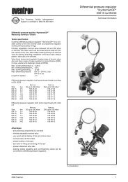
Pressure loss chart for <strong>“Unibox</strong> E RTL”<br />
P-deviation<br />
Pressure loss chart <strong>“Unibox</strong> E T” at 2 K P-deviation and<br />
<strong>“Unibox</strong> E plus”, RTL completely opened<br />
Presetting<br />
at 1 K P-deviation<br />
Presetting<br />
6 2006 <strong>Oventrop</strong><br />
Pressure loss ∆p [mbar]<br />
Pressure loss ∆p [mbar]<br />
Pressure loss ∆p [mbar]<br />
OVENTROP UK LTD.<br />
Unit I – The Loddon Centre<br />
Wade Road<br />
Basingstoke, Hampshire RG24 8FL<br />
Great Britain<br />
Telephone (01256) 330441<br />
Telefax (Sales) (01256) 330525<br />
Telefax (General) (01256) 470970<br />
E-Mail sales@oventrop.co.uk<br />
Flow rate V<br />
·<br />
[l/s]<br />
Flow rate V<br />
·<br />
[l/s]<br />
Flow rate V<br />
·<br />
[l/s]<br />
Pressure loss ∆p [Pascal]<br />
Pressure loss ∆p [Pascal]<br />
Pressure loss ∆p [Pascal]<br />
F. W. OVENTROP GmbH & Co. KG<br />
Paul-<strong>Oventrop</strong>-Straße 1<br />
D-59939 Olsberg<br />
Germany<br />
Telephone (02962) 82-0<br />
Telefax (02962) 82-450<br />
E-Mail mail@oventrop.de<br />
Internet www.oventrop.de