

Exeter V40 Total Hip Replacement Arthroplasty procedure - eDoctor
Exeter V40 Total Hip Replacement Arthroplasty procedure - eDoctor
Exeter V40 Total Hip Replacement Arthroplasty procedure - eDoctor

Create successful ePaper yourself
Turn your PDF publications into a flip-book with our unique Google optimized e-Paper software.
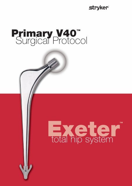
Primary <strong>V40</strong> <br />
Surgical Protocol<br />
<strong>Exeter</strong><br />
total hip system
<strong>V40</strong> <br />
Cement<br />
It is important to note that<br />
different types of bone cement<br />
set at various timescales and<br />
the temperature of the<br />
operating theatre also effects<br />
the setting time.<br />
Acetabular Cementing<br />
Typically using Simplex®<br />
bone cement with a theatre<br />
temperature of 21°C, cement<br />
injection and pressuration<br />
should take place 6–8 minutes<br />
after commencement of<br />
mixing.<br />
Femoral Cementing<br />
Typically using Simplex®<br />
bone cement and with a<br />
theatre temperature of 21°C,<br />
the cement should be<br />
inserted into the cavity at<br />
2 1 ⁄2–3 minutes after<br />
commencement of mixing.<br />
The stem is typically inserted<br />
approximately 6 minutes<br />
after the start of mixing.<br />
1<br />
Head diameter<br />
mm<br />
22<br />
26<br />
28<br />
30<br />
32<br />
36<br />
SURGICAL PROTOCOL HIGHLIGHTS<br />
44mm<br />
1. Pre-operative Planning:<br />
Pre-operative templating is important to select the correct<br />
implant sizes, their positions and the minimum cement<br />
mantle thickness required. Any surgical approach can be<br />
used, and where appropriate, it is important that the patient<br />
is firmly and accurately supported in the lateral decubitus<br />
position.<br />
6. Femoral Preparation<br />
The femur is prepared by using the tapered reamers,<br />
Capener long-handled gouge and the appropriate rasp<br />
selected during the pre-op templating. It is important to<br />
open the femur laterally in order to achieve neutral<br />
alignment of the stem. The rasp creates a cavity which will<br />
hold the stem with a complete cement mantle of at least<br />
2mm around it. Usually a smaller rasp is used initially<br />
finishing with the rasp corresponding to the template<br />
considered appropriate for the femur. It is a serious<br />
mistake to over-rasp the canal and remove too much<br />
cancellous bone.<br />
2. Neck Resection<br />
Full exposure of both the acetabulum and the<br />
proximal femur is necessary to prepare,<br />
cement and implant the components. As the<br />
<strong>Exeter</strong> stem has no collar, the level and<br />
orientation of neck resection are not critical.<br />
7. Trial Reduction<br />
The appropriate head trial is positioned onto the<br />
rasp. A trial reduction will verify the correct stem<br />
size, offset and position. A metal spigot protector<br />
may be applied onto the rasp and the stem<br />
introducer attached. A diathermy mark or short K<br />
wire can then be used to indicate the correct length<br />
according to the leg length device.
3. Acetabular Preparation<br />
The acetabulum is reamed to reveal bleeding<br />
subchondral bone (trabecular bone wherever<br />
possible). After removing any osteophytes,<br />
fixation pits are made with multiple drill holes.<br />
The sucker-aspirator may be used in the dome<br />
of the ilium.<br />
Trial cups are inserted to select the cup which<br />
will give a minimum of 2mm of cement mantle.<br />
After lavage, the bone should be dried to<br />
provide a sound key for the cement.<br />
8. Plug Introduction<br />
The correct intramedullary plug<br />
size is selected by using the<br />
<strong>Exeter</strong> plug trials. The<br />
corresponding sized plug is<br />
implanted to provide a firm seal<br />
for pressurising the cement. The<br />
femur is then cleaned with lavage<br />
and dried to provide a clean dry<br />
surface prior to cement injection.<br />
4. Acetabular Cementing<br />
Cement is introduced into the acetabulum<br />
and pushed firmly into the fixation pits.<br />
The acetabular pressuriser is placed over<br />
the cement and inflated to create a seal. It<br />
is pushed onto the cement to counter the<br />
bleeding pressure and to force cement into<br />
the bone. Please see cement panel for typical<br />
setting times. Typically Simplex® bone<br />
cement will be pressurised for 6 to 7<br />
minutes before the cup is introduced.<br />
9. Femoral Cementing<br />
After retrograde filling with cement, the spout of the<br />
gun is cut off at the seal, and the seal is then forced<br />
onto the end of the femur to form a closed cavity<br />
appropriate for pressurisation.The remaining<br />
cement is injected and the pressure maintained until<br />
immediately prior to stem insertion.<br />
Typically, with Simplex® bone cement and a theatre<br />
temperature of 21 degrees centigrade the stem will<br />
be introduced 5 to 6 minutes after commencement<br />
of mixing.<br />
5. Cup Insertion<br />
The acetabular cup is placed on the introducer. The shaft is held<br />
so that the long alignment rod is vertical and the short one<br />
horizontal and perpendicular to the patient’s long axis. Rotating<br />
the handle of the introducer will place the skirt in the desired<br />
position.<br />
The cup is implanted about 3 minutes before the cement<br />
polymerises, and is held in place with the cup pusher until the<br />
cement is completely set.<br />
10. Stem Introduction<br />
With the centraliser in place, the stem is inserted in one<br />
continuous smooth movement down the centre of the femur.<br />
During insertion, pressure is maintained by the thumb placed<br />
medially over the area of the calcar. The stem can be inserted<br />
through the stem seal to its final position, or the seal can be<br />
positioned after the stem is inserted, and held in place until the<br />
cement polymerises.
<strong>V40</strong> <br />
3<br />
S U R G I C A L P R O T O C O L<br />
Head diameter<br />
mm<br />
22<br />
26<br />
28<br />
30<br />
32<br />
36<br />
EXETER “<br />
total hip system<br />
“<br />
<strong>V40</strong><br />
44mm No.2<br />
0580-1-442<br />
20% oversize to allow<br />
for X-Ray magnification<br />
Graduated marker<br />
indicating minimum<br />
cement mantle 2mm<br />
Alignment points:<br />
Proximal Stem seal<br />
Neck resection level<br />
The stem centraliser will compress to a minimum of 10mm.<br />
If the femoral canal is less than this the centraliser wings<br />
should be removed.<br />
1. Pre-operative Planning:<br />
Pre-operative templating is important and<br />
will usually allow the surgeon to select an<br />
implant of the appropriate size and offset<br />
for the hip to be reconstructed, and to plan<br />
the positions in which the components<br />
should be placed (Fig. 1).<br />
Allowance must be made for the need to<br />
obtain a complete mantle of cement for<br />
the femoral component that is to be used.<br />
Alongside the stem profiles on the<br />
templates are marks that demonstrate the<br />
extent of cement mantles of varying<br />
widths. The first mark indicates the<br />
minimum mantle allowed. It may be<br />
necessary to template the opposite hip.<br />
44mm<br />
Figure 1<br />
2. Surgical Exposure<br />
Figure 2<br />
The <strong>Exeter</strong> <strong>Hip</strong> can be implanted<br />
through the direct lateral or lateral<br />
approaches or through the Southern or<br />
posterior approach. The Southern or<br />
posterior approach is featured in this<br />
technique manual. Whichever approach is<br />
used, a full exposure of both the<br />
acetabulum and the proximal femur is<br />
essential for effective preparation of the<br />
bony cavities, cementing, and implant<br />
insertion.<br />
Appropriate soft tissue releases shall be<br />
performed to allow adequate exposure of<br />
the whole socket rim and mobilisation of<br />
the proximal femur.<br />
The patient must be firmly and accurately<br />
supported in the lateral decubitus position<br />
(Fig. 2) to help ensure that the acetabular<br />
component is orientated correctly. It is<br />
also important not to flex the contralateral<br />
hip too much as this could reduce the<br />
lumbar lordosis, with subsequent risk of<br />
retroversion of the cup.
Either the femur or the acetabulum may<br />
be prepared first.<br />
3. Femoral Neck Resection<br />
The level and orientation of neck resection<br />
is not critical as the <strong>Exeter</strong> <strong>Hip</strong> Stem has<br />
no collar or other features which will affect<br />
the osteotomy line. The level of section<br />
usually runs from mid-way between the<br />
upper margin of the lesser trochanter and<br />
the inferior aspect of the head, to the<br />
upper surface of the base of the neck<br />
(Fig. 3).<br />
4. Femoral Preparation<br />
The leg is positioned and held with a<br />
femoral elevator. A gluteus medius<br />
retractor may be to fully expose the<br />
proximal femur (Fig. 4).<br />
Figure 3<br />
Figure 4
<strong>V40</strong> <br />
5<br />
The opening in the cut surface of the<br />
femoral neck is developed from within the<br />
calcar toward the proximal aspect of the<br />
greater trochanter as far as necessary to<br />
allow the <strong>Exeter</strong> stem to be passed<br />
directly down the femur in the long axis of<br />
the medullary canal.<br />
The cavity is opened using the straight<br />
Capener type gouge or a box chisel, to<br />
undercut the base of the neck, and develop<br />
the slot into the trochanteric region<br />
(Fig. 5), if necessary using a rongeur to<br />
resect the bone of the neck after<br />
undercutting. The taper pin reamer is used<br />
to develop the slot to ensure that the<br />
femoral stem can be inserted down the<br />
mid-line of the femur.<br />
Figure 6<br />
The taper pin reamer should be positioned<br />
within the canal so that it aligns with the<br />
popliteal space (Fig. 6), or with the patella<br />
if the lateral approach is being used.<br />
Trabecular bone is removed from within<br />
the calcar until a strong layer is<br />
encountered, usually this will leave<br />
2 - 3mm of strong trabecular bone.<br />
This layer of trabecular bone provides a<br />
firm foundation for the micro-interlock of<br />
cement within the bone.<br />
Figure 5
A<br />
B<br />
C<br />
D<br />
Figure 7 - use of rasps<br />
A smaller rasp is used initially finishing<br />
with the rasp corresponding to the<br />
template considered appropriate for the<br />
femur. It is a serious mistake to over-rasp<br />
the canal and remove too much cancellous<br />
bone.<br />
If excess force is required to introduce a<br />
rasp to this level then the canal should be<br />
further developed with the taper pin<br />
reamer or gouge, without compromising<br />
the layer of strong trabecular bone.
<strong>V40</strong> <br />
7<br />
5. Acetabular Preparation<br />
The true acetabular lip is identified,<br />
osteophytes are removed with any<br />
redundant capsular folds, and the<br />
transverse acetabular ligament is left<br />
intact. The true floor of the socket is<br />
identified.<br />
Figure 8<br />
Grater reamers are used to remove all<br />
remnants of articular cartilage and to<br />
shape the cavity with exposure of a<br />
cancellous surface where feasible, except<br />
on the medial wall. The curtain osteophyte<br />
is then removed. The cortical layer above<br />
the teardrop is never removed. The reamer<br />
shaft should be orientated at 40° of<br />
abduction and 10°-15° of anteversion<br />
(Fig. 8).<br />
Care must be taken not to enlarge the<br />
antero-posterior diameter of the<br />
acetabulum, unduly thinning the anterior<br />
and posterior walls.<br />
A gouge may optionally be used to create<br />
fixation pits in the three main bones of the<br />
pelvis (Fig. 9A). Multiple drill holes are<br />
then made in the ilium, pubis and ischium<br />
for fixation (Fig. 9B).<br />
Supplementary 6mm drill holes should<br />
also be used where appropriate, especially<br />
just within the rim of the acetabulum.<br />
Trial cups are inserted into the prepared<br />
acetabulum to confirm or change the<br />
selection of cup made on the basis of preoperative<br />
templating. The selected trial<br />
cup must be completely surrounded by<br />
bone (Fig. 10A).<br />
The pressuriser is tested against the<br />
acetabular rim to make certain that a<br />
perfect seal is obtained (Fig. 10B).<br />
Cancellous autograft chips taken during<br />
the preparation of the upper femur or<br />
during the preparation of the acetabular<br />
pits should be packed under the transverse<br />
ligament to ensure that the space<br />
underneath is totally occluded. Any other<br />
rim deficiencies should be made good<br />
with impacted cancellous chips, and it is<br />
usual to place a layer of cancellous bone<br />
chips on the cortical floor of the<br />
acetabulum just above the teardrop. These<br />
are held in place with the outer side of a<br />
long spoon whilst the acetabulum is<br />
cleaned.
6. Acetabular Cementing<br />
and Pressurisation<br />
The acetabulum is thoroughly cleaned<br />
using lavage. It is irrigated with<br />
Hartmann’s solution, and packed with<br />
swabs soaked in 10 vols. hydrogen<br />
peroxide whilst the Simplex® bone cement<br />
is being mixed. These swabs are held<br />
firmly in place using the cup pusher until<br />
the cement is ready to use.<br />
A sucker-aspirator may be used to assist<br />
cement intrusion and prevent blood<br />
accumulating at the interface. The cement<br />
mass is placed into the socket, and cement<br />
is thumbed into the pits. The level of<br />
cement in the acetabulum should be<br />
approximately 5mm below the acetabular<br />
rim to ensure a good seal by the<br />
pressuriser (Fig. 10C).<br />
A B<br />
A<br />
C<br />
Figure 10<br />
Figure 9<br />
B
<strong>V40</strong> <br />
9<br />
Figure 11<br />
Figure 12<br />
The cement is pressurised using the<br />
acetabular pressuriser. A piece of gauze<br />
and a latex sheet are placed over the<br />
pressuriser balloon. The balloon is<br />
inflated, then applied to the socket rim<br />
and then pushed with considerable force.<br />
Typically using Simplex® cement, and<br />
with a theatre temperature of 21°C, the<br />
cement should be mixed for at least<br />
1minute, left to stand for at least 1 minute<br />
and inserted into the cavity at<br />
approximately 3 - 4 minutes.<br />
Pressurisation should continue until the<br />
viscosity of the cement has risen<br />
sufficiently to overcome the bleeding<br />
pressure of the bone.<br />
A quantity of cement should be held in the<br />
surgeon’s hands to help ascertain when<br />
cement reaches the stage when the cup<br />
should be implanted. Normally this stage<br />
will be reached at 6-8 minutes after<br />
commencement of mixing.<br />
The pressuriser is removed by deflating the<br />
balloon, then breaking the seal by lifting<br />
the gauze swab and peeling back the latex<br />
sheet.
7. Acetabular Implantation<br />
The acetabular cup is then implanted. It is<br />
positioned onto the introducer (Fig. 12),<br />
and pushed into the acetabulum.<br />
Considerable force should be necessary to<br />
overcome the viscosity of the cement, but<br />
the cup should not be allowed to bottom<br />
out. The initial force applied is medial and<br />
then superiorly.<br />
The cup is correctly positioned when the<br />
face of the cup is at an angle of<br />
40° of abduction and 10°-15° of<br />
anteversion (Fig. 13). The guide rods on<br />
the introducer will place the cup in this<br />
orientation if they are correctly used and<br />
provided the patient has been accurately<br />
placed and stabilised in the lateral<br />
decubitus position (as detailed previously<br />
in Fig. 2). If the direct lateral or lateral<br />
approach has been used the cup may be<br />
placed in a more neutral position. During<br />
insertion the cup should be rotated so that<br />
the apex of the skirt should lie posterolaterally<br />
either at 10 o’clock or 2 o'clock<br />
according to the side.<br />
The long alignment rod should be vertical,<br />
and the short pin horizontal and at 90º to<br />
the patient's long axis. There should be an<br />
adequate thickness of cement between the<br />
cranial surface of the cup and the<br />
acetabular bone of no less than 3 - 4mm.<br />
This layer will of course be appreciably<br />
thicker in the region of the fixation pits.<br />
Once the cup has been properly<br />
positioned, it is held in place with light<br />
pressure using the universal cup pusher,<br />
with the appropriately sized trial femoral<br />
head, so that there is no tendency for the<br />
cup to be moved within the cement mantle<br />
whilst the cement is polymerising<br />
(Fig. 14). Avoid using a damaged trial head<br />
which may lock in the cup and cause it to<br />
move.<br />
After cement polymerisation the fixation<br />
is checked by rocking the cup and<br />
watching for evidence of ‘pumping’ of<br />
blood at the cement-bone junction.<br />
Evidence of this indicates inadequate<br />
fixation, and immediate revision should<br />
be considered.<br />
Figure 14<br />
Significant osteophytes should be removed<br />
to prevent premature impingement of the<br />
femoral component or femur on the<br />
acetabular rim at the extremes of<br />
movement. If during trial reduction the<br />
neck of the prosthesis impinges on the<br />
skirt then that part of the skirt should be<br />
resected.<br />
90°<br />
Figure 13
<strong>V40</strong> <br />
11<br />
8. Trial reduction<br />
The proximal femur is re-exposed and the<br />
appropriate head trial is positioned onto<br />
the rasp. A trial femoral head is placed<br />
over the spigot and the hip is reduced.<br />
Head trials are colour coded; blue is for a<br />
minus (-) neck length, black for neutral<br />
and green for a plus (+) neck length.<br />
Correct restoration of leg length may be<br />
assessed by comparing the relative<br />
positions of the femoral condyles.<br />
If the leg has been shortened this can be<br />
compensated for by implanting the stem<br />
to a higher level. Leg lengthening can be<br />
compensated by impacting the rasp<br />
further into the femur and repeating the<br />
trial reduction. A smaller rasp may be<br />
required.<br />
15<br />
Figure 15<br />
When the correct leg length has been<br />
achieved, the trial femoral head is removed<br />
and a metal spigot protector is positioned<br />
over the neck trial. The stem introducer is<br />
mounted onto the metal spigot protector<br />
ensuring that it is aligned with the rasp.<br />
The femur can be marked with diathermy<br />
and methylene blue dye at the level<br />
indicated by the leg length gauge<br />
(Fig. 15). Alternatively a K wire may be<br />
used. The spigot protector and neck trials<br />
are then removed. The rasp handle is<br />
reattached and the rasp removed.
16A<br />
16B<br />
Figure 16A & B, 17<br />
9. Further Femoral Preparation<br />
The correct intramedullary plug size is<br />
selected by using <strong>Exeter</strong> plug trials. The<br />
appropriate size of intramedullary plug is<br />
mounted on the introducer (Fig. 16A),<br />
and driven in 17-18cm distal to the tip of<br />
the greater trochanter (Fig. 16B).<br />
A tight fit for the plug is essential.<br />
The proximal femoral seal and backing<br />
plate are positioned onto the cement gun<br />
nozzle. These are placed over the proximal<br />
end of the femur to ensure a good fit<br />
(Fig. 17). If a good fit cannot be achieved,<br />
the other size of seal should be tried, or the<br />
femoral slot altered to ensure a tight seal. If<br />
a tight fit cannot be obtained after any of<br />
these measures, the use of the gun should<br />
be abandoned and the ‘suck-down’<br />
technique should be used with doughy<br />
cement and vigorous finger packing.<br />
17<br />
The canal is thoroughly cleaned using<br />
lavage. A catheter is placed in the distal<br />
end of the canal and connected to suction.<br />
Ribbon gauze soaked in 10 vols. hydrogen<br />
peroxide is packed into the femur to<br />
maintain haemostasis in the canal and to<br />
provide a clean dry surface into which the<br />
cement can key. The ribbon gauze and<br />
suction catheter are removed immediately<br />
before cement injection starts.
<strong>V40</strong> <br />
13<br />
10. Femoral Cementing<br />
18A<br />
18B<br />
Using Simplex® bone cement, the cement<br />
should be mixed in a mixing bowl for 1<br />
minute and then poured into the cement<br />
barrel, which should be left to stand for 30<br />
seconds. Three mixes may be necessary for<br />
large femora. The nozzle is fixed to the<br />
barrel, the femoral seal and backing plate<br />
positioned, and the cement gun is primed.<br />
Cement is introduced in a retrograde (ie.<br />
from distal to proximal) fashion<br />
(Fig. 18A). Typically, using Simplex® bone<br />
cement and with a theatre temperature of<br />
21°C, this is usually 2 1 ⁄2 to 3 minutes after<br />
commencement of mixing. As the cement<br />
reaches the upper part of the canal, the<br />
nozzle of the gun is cut off distal to the<br />
femoral seal.<br />
The femoral seal is then impacted forcibly<br />
onto the upper end of the femur, and the<br />
remaining cement is slowly pumped into<br />
the femur (Fig. 18B). This action will<br />
maintain a steady pressure to overcome<br />
the bleeding pressure inside the femur.<br />
Figure 18A & B<br />
When pressurisation is correctly<br />
performed, a steady extrusion of fat<br />
through the walls of the upper femur may<br />
be seen.<br />
Cement injection and pressurisation is<br />
continued until the viscosity of the cement<br />
starts rising. Typically, using Simplex bone<br />
cement and with a theatre temperature of<br />
21°C, this is seldom less than 6 minutes<br />
from commencement of mixing, judged<br />
by a small sample held in the hand. The<br />
femoral stem is then inserted.<br />
The aim should be to delay stem insertion<br />
as long as possible remembering that<br />
during stem insertion interface pressures<br />
in the canal are directly related to the<br />
viscosity of the cement.
19A<br />
19B<br />
19C<br />
Figure 19A, B & C<br />
11. Stem Implantation<br />
The hollow centraliser must be used with<br />
the <strong>Exeter</strong> stem. Each <strong>Exeter</strong> <strong>V40</strong><br />
stem is supplied with a winged and a<br />
wingless centraliser. If an intramedullary<br />
plug of less than 10mm is used it may be<br />
preferable to use a wingless centraliser.<br />
The use of the hollow centraliser prevents<br />
‘end-bearing’ of the stem, and ensures that<br />
the proximal, expanded taper of the stem<br />
will engage properly in the cement mantle.<br />
The selected stem is mounted on the<br />
introducer. It is important to note that the<br />
handle of the introducer is exactly in the<br />
mid-line of the stem and so the introducer<br />
and the stem can be lined up with the<br />
medullary canal of the femur. The stem<br />
introducer can be used with one hand, and<br />
has a smooth trigger action which releases<br />
the introducer pin from the dimple in the<br />
lateral shoulder of the stem implant.<br />
The stem is introduced through the<br />
proximal femoral opening closer to the<br />
posterior femoral cortex than the anterior,<br />
and aiming at the middle of the popliteal<br />
fossa if the Southern or posterior<br />
approach is used, or the patella if the direct<br />
lateral or lateral approach is used<br />
(Fig. 19A).<br />
The stem can be driven into the canal<br />
through the stem seal and its backing plate<br />
which should be held firmly in position on<br />
the cut surface of the femoral neck.<br />
Otherwise the stem is driven into place<br />
with the surgeon’s thumb occluding the<br />
medial exit from the upper end of the<br />
femur between the stem and the calcar, to<br />
further pressurise the cement into the<br />
cancellous bone (Fig. 19B). During stem<br />
insertion, there should be further<br />
extrusion of fat through the walls of the<br />
femur.
<strong>V40</strong> <br />
15<br />
20A<br />
20B<br />
20C<br />
20D<br />
Figure 20A, B, C & D<br />
The insertion should be brisk until the<br />
stem reaches a position approximately<br />
1cm. above its final position. Insertion<br />
thereafter should be slower, gradually<br />
bringing the stem to its final<br />
predetermined position as judged by the<br />
leg length gauge (Fig. 19C). The femur can<br />
be marked with diathermy and methylene<br />
blue dye at the level indicated by the<br />
gauge.<br />
When the final position has been reached<br />
and the introducer removed, the stem seal<br />
and backing plate are positioned and firm<br />
pressure maintained on the top of the<br />
cement until it polymerises (Fig. 20A, B &<br />
C). Ensure that the stem does not back out<br />
during cement polymerisation. The<br />
surgeon may wish to use the stem seal<br />
pusher to apply firm pressure onto the<br />
stem seal until the cement polymerises<br />
(Fig. 20D).<br />
The surgeon should remove all cement<br />
from the cut surface of the cortical calcar.
12. Reduction<br />
The spigot protector is then removed and<br />
the spigot thoroughly cleaned.<br />
A further trial reduction may be carried<br />
out using the appropriate trial heads on<br />
the <strong>V40</strong> spigot. Checks are then made<br />
again for correct leg length and stability.<br />
Reduced and increased neck lengths are<br />
available. The appropriate size of femoral<br />
head is removed from its packaging and<br />
placed over the stem spigot. It is secured in<br />
place by firm blows with the palm of the<br />
hand. Alternatively, the head may be<br />
pushed on by hand & rotated 10º. Neither<br />
excess force, impaction nor hard<br />
instruments should be used as this may<br />
damage the fine polished surface<br />
(Fig. 21).<br />
Figure 21A, B and C<br />
21A 21B 21C
<strong>V40</strong> <br />
17<br />
P O S T - O P E R A T I V E M A N A G E M E N T<br />
DAY OF OPERATION<br />
Encourage breathing exercises. Check that<br />
foot, ankle and quadriceps exercises are<br />
carried out hourly by the patient.<br />
FIRST POST-OPERATIVE<br />
DAY<br />
Supervise breathing and foot, ankle and<br />
quadriceps exercises. Begin resisted<br />
exercises for the un-operated leg and<br />
assisted active exercises for the operated<br />
leg, including external rotation and active<br />
hip abduction with the weight of the leg<br />
being taken by the physiotherapist. The<br />
patient is encouraged to do the<br />
movements with assistance from the<br />
physiotherapist. Avoid internal rotation,<br />
sitting erect or the use of too many<br />
pillows. Younger patients may stand on<br />
the first post-operative day.<br />
SECOND POST-<br />
OPERATIVE DAY<br />
Continue with breathing exercises, foot,<br />
ankle, quads and gluteal exercises. Remove<br />
the drains. The physiotherapist should<br />
help the patient to get out of bed, after<br />
ensuring that the bed is at the correct<br />
height. The patient should wear shoes.<br />
Knee flexion is encouraged with the<br />
patient sitting sideways on the edge of the<br />
bed. In getting into a standing position the<br />
patient should take as much weight as<br />
possible on the non-operated leg with<br />
support from the physiotherapist who<br />
should stand on the same side as the<br />
affected hip with a stick in the patient's<br />
opposite hand or another helper on that<br />
side if necessary.<br />
In the standing position the patient<br />
should be shown how to stand and walk.<br />
The patient should be encouraged to take<br />
normal steps, although the first walk<br />
should be kept within the patient's<br />
tolerance. Touch weight bearing is<br />
advisable except in the elderly.<br />
The patient must be taught to turn around<br />
without straining the hip in a rotatory<br />
position, and be taught how to sit and<br />
stand correctly from a chair.<br />
The physiotherapist should teach the<br />
patient how to get back into, and out of<br />
bed, and assist them to do so, preventing<br />
internal rotation and adduction of the hip<br />
during these manoeuvres.<br />
THIRD POST-OPERATIVE<br />
DAY<br />
All static exercises and breathing exercises<br />
are supervised. The patient may be taught<br />
to turn prone and is encouraged to lie<br />
prone for two periods of twenty minutes<br />
daily.<br />
FOURTH POST-<br />
OPERATIVE DAY<br />
Continue supervision of static exercises<br />
and breathing exercises. The physiotherapist<br />
should continue to supervise<br />
correct walking and the patient can<br />
increase the number and duration of the<br />
walks. The patient is instructed in getting<br />
into a sitting position on the toilet. The<br />
physiotherapist should start to teach the<br />
patient to lift the leg on to the bottom step<br />
of the stairs flexing the hip and knee whilst<br />
avoiding internal rotation.<br />
FIFTH POST-OPERATIVE<br />
DAY<br />
Continue supervision of static exercises.<br />
The patient should be able to walk to the<br />
toilet alone. The physiotherapist should<br />
start the patient walking up and down<br />
steps and generally increase walking. A<br />
post-operative X-ray is taken. The patient<br />
should be independent upon discharge<br />
and allowed home with suitable walking<br />
aids supplied by the occupational<br />
therapist. The patient should avoid<br />
excessive flexing of and internally rotating<br />
the hip.
The first post-operative follow-up visit is<br />
usually two to three months after surgery.<br />
X-rays at this stage are only taken if bone<br />
grafting was performed. If the patient's<br />
condition is satisfactory at three months,<br />
the next appointment should be one year<br />
from the time of operation. X-rays should<br />
be taken. If these are satisfactory, further<br />
follow-up visits are not needed, unless the<br />
patient develops symptoms suggesting any<br />
problem with the arthroplasty. However,<br />
arrangements should be made for the<br />
arthroplasty to be viewed by X-ray two<br />
years from the time of the operation.<br />
Provided these films are satisfactory, no<br />
further films need be taken for seven to<br />
eight years, unless the patient develops<br />
symptoms suggesting problems with the<br />
arthroplasty. From eight years on, films<br />
should again be taken at two yearly<br />
intervals.
Excellent Long Term Results<br />
• From the original 433 <strong>Exeter</strong> <strong>Hip</strong>s, with<br />
revision for aseptic stem loosening as the<br />
end-point, survivorship into the 33rd<br />
year of follow-up is 91.46% 1 .<br />
1 Presentation, European <strong>Hip</strong> Society, June 2004.<br />
This document is intended solely for the use of healthcare professionals.<br />
The information presented in this brochure is intended to demonstrate the breadth of Stryker product<br />
offerings. Always refer to the package insert, product label and/or user instructions before using any Stryker<br />
product. Products may not be available in all markets. Product availability is subject to the regulatory or<br />
medical practices that govern individual markets. Please contact your Stryker representative if you have<br />
questions about the availability of Stryker products in your area.<br />
Products referenced with designation are trademarks of Stryker.<br />
Products referenced with ® designation are registered trademarks of Stryker.<br />
Literature Number: EXEOT01E02<br />
MTX/GS 10/06<br />
Copyright © 2006 Stryker<br />
Stryker SA<br />
Cité-Centre<br />
Grand-Rue 90<br />
1820 Montreux<br />
Switzerland<br />
t : +41 21 966 12 01<br />
f : +41 21 966 12 00<br />
www.europe.stryker.com