Full Catalog - Schaefer, Inc.
Full Catalog - Schaefer, Inc.
Full Catalog - Schaefer, Inc.

Create successful ePaper yourself
Turn your PDF publications into a flip-book with our unique Google optimized e-Paper software.
Power Conversion Systems<br />
<strong>Schaefer</strong> – the Power to make it happen .<br />
Power Supplies Converters Inverters Rectifi ers Chargers Systems
workforce<br />
experience<br />
customer orientation<br />
fl exibility<br />
reliability<br />
quality<br />
contact<br />
Company profi le<br />
Schäfer Elektronik, founded in 1969, has grown to a dedicated<br />
workforce of 140 people in Germany, Ireland, and the USA.<br />
Thanks to decades of experience in design and manufacturing of<br />
power supplies, <strong>Schaefer</strong> offers a large variety of products, options, and<br />
enhancement features. In the fi eld of high power requirements, <strong>Schaefer</strong><br />
has achieved and continues to command a leading position.<br />
Requirements are analyzed by a group of experts in dialog with the<br />
customer resulting in an individual concept.<br />
With the production located next to the development department an<br />
optimal interaction can be accomplished during all stages of a project.<br />
Hence the customer gets tailor-made solutions for large or small quantity<br />
requirements.<br />
<strong>Schaefer</strong> power supplies are often used for applications which demand<br />
a high level of reliability under severe environmental conditions, e. g.<br />
■ Railroad industry<br />
■ Automotive industry<br />
■ Telecommunication<br />
■ Power generation plants<br />
■ Chemical plants and oil refi nery<br />
■ Factory automation<br />
■ Military industry<br />
Development guidelines, arduous selection of industrial components<br />
regarding their load criteria and temperature performance as well<br />
as many test procedures during all steps of production ensure the<br />
highest product quality. In addition, <strong>Schaefer</strong> pursues a full supplier<br />
management according to ISO 9001 which guarantees permanent<br />
improvement of the products especially within the turbulent market of<br />
electronic components.<br />
Through headquarters in Germany, the USA offi ce, and an inter national<br />
network of representatives prompt technical support is provided<br />
worldwide.
Converters Selector Guide<br />
1<br />
Series Power Power DC input DC input AC input Page<br />
[V]<br />
1-phase 1-phase 3-phase<br />
with<br />
PFC<br />
0 – 80 W<br />
80 – 200 W<br />
200 – 550 W<br />
550 – 1500 W<br />
1.5 – 4 kW<br />
4 – 10 kW<br />
10 – 30 kW<br />
10 V<br />
18 V<br />
80 V<br />
320 V<br />
380 V<br />
640 V<br />
800 V<br />
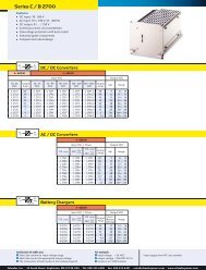
Switch Mode DC/DC Converters, AC/DC Power Supplies and Battery Chargers<br />
C / B 200 40 – 50 W 10 – 380 4<br />
NEW CH / CP / BP 200 150 W 18 – 320 6<br />
C / B 300 100 – 150 W 10 – 380 8<br />
C / B 1200 120 – 200 W 10 – 380 10<br />
C / B 500 180 – 250 W 10 – 380 12<br />
S 600 200 – 350 W 10 – 380 14<br />
C / CP / B / BP 1300 250 – 400 W 10 – 380 16<br />
C / B 2500 300 – 400 W 18 – 380 18<br />
C / B 600 300 – 500 W 10 – 380 20<br />
C / B 1500 400 – 600 W 10 – 380 22<br />
NEW C / B 2700 450 – 600 W 18 – 380 24<br />
C / B 2600 650 – 800 W 18 – 380 26<br />
C / B 3500 700 – 850 W 18 – 640 28<br />
C / B 1600 750 – 1200 W 10 – 380 30<br />
C / CP / B / BP 3700 1000 – 1250 W 18 – 640 32<br />
NEW C / B 4500 900 – 1600 W 10 – 800 34<br />
C / B 3600 1.4 – 1.7 kW 18 – 800 36<br />
C / CP / B B / BP 4700 4700 1.2 – 2.5 kW 10 – 800 38<br />
C / B 3800 2 – 2.5 kW 18 – 800 40<br />
C / B 4800 2.4 – 5 kW 10 – 800 42<br />
C 5600 / 5700 2.4 – 7.5 kW 10 – 80 44<br />
NEW C / B 5100 2.4 – 5 kW 320 – 800 46<br />
C / B 5200 4 – 5 kW 80 – 800 48<br />
C / B 5600 4.5 – 6 kW 80 – 800 50<br />
C / B 5300 5.6 – 7.5 kW 80 – 800 52<br />
NEW CW / BW 5300 5.6 – 8 kW 80 – 800 54<br />
C / B 5700 6.5 – 8 kW 80 – 800 56<br />
C / B 5400 7.5 – 10 kW 80 – 800 58<br />
C / B 5800 8.5 – 12 kW 80 – 800 60<br />
NEW CW / BW 5500 7.5 – 15 kW 80 – 800 62<br />
C / B 6400 22 kW 320 – 800 64<br />
NEW CW / BW 6600 30 kW 320 – 800 66<br />
Switch Mode DC/DC Converters and AC/DC Power Supplies with Additional Outputs<br />
M 200 30 – 40 W 10 – 380 69<br />
M 300 60 – 80 W 10 – 380 70<br />
M 1200 110 – 160 W 10 – 380 71<br />
SM 600 180 – 300 W 10 – 380 72<br />
M 1300 220 – 320 W 10 – 380 73<br />
M 600 270 – 450 W 10 – 380 74<br />
M 2600 600 – 700 W 18 – 380 75<br />
Order example<br />
Assistance in table use:<br />
1 Select the column for input voltage range.<br />
2 Select the row for the appropriate output voltage.<br />
3 The intersection of both results in the module required.<br />
18 – 36<br />
VDC<br />
CH 220<br />
CH 221<br />
CH 222<br />
CH 223<br />
...<br />
CH 227<br />
CH 228<br />
36 – 75<br />
VDC<br />
1<br />
CH 230<br />
CH 231<br />
CH 232<br />
2 3<br />
CH 233<br />
3<br />
...<br />
CH 237<br />
CH 238<br />
For example:<br />
1 input voltage = 48 VDC<br />
2 output voltage = 12 VDC @ 12 A<br />
3 results in a CH 232 module.<br />
Input VDC Output VDC<br />
45 – 90<br />
VDC<br />
CH 240<br />
CH 241<br />
CH 242<br />
CH 243<br />
...<br />
CH 247<br />
CH 248<br />
80 –160<br />
VDC<br />
CH 250<br />
CH 251<br />
CH 252<br />
CH 253<br />
...<br />
CH 257<br />
CH 258<br />
160 – 320<br />
VDC<br />
CH 270<br />
CH 271<br />
CH 272<br />
CH 273<br />
...<br />
CH 277<br />
CH 278<br />
Output<br />
Amps<br />
20<br />
15<br />
12<br />
10<br />
...<br />
1.2<br />
0.6<br />
Adj. Range<br />
5<br />
9<br />
2 12<br />
15<br />
...<br />
110<br />
220<br />
4.5 – 5.5<br />
8 – 10<br />
11 – 13<br />
14 – 16<br />
...<br />
100 – 130<br />
200 – 250<br />
Conversion table<br />
Height: 1 U = 44.45 mm<br />
1 U = 1.75“<br />
Width: 1 TE = 5.08 mm<br />
1 TE = 0.2“<br />
1” = 25.4 mm<br />
Weight: 1 kg = 2.2 lbs<br />
<strong>Schaefer</strong>, <strong>Inc</strong>. · 45 South Street, Hopkinton, MA 01748, USA · Tel: 508-435-6400 · Fax: 508-435-6401 · sales@schaeferpower.com · www.schaeferpower.com
DC output 1 DC output 1 (nominal voltage) DC output 2 - 4 Package Cooling<br />
[V]<br />
5 V<br />
9 V<br />
12 V<br />
15 V<br />
24 V<br />
28 V<br />
48 V<br />
60 V<br />
110 V<br />
200 V<br />
220 V<br />
400 V<br />
800 V<br />
Eurocassette<br />
/<br />
19” Rack<br />
mount<br />
Height [U]<br />
5 – 250 3<br />
5 – 250 3<br />
5 – 250 3<br />
5 – 250 6<br />
5 – 250 3<br />
5 – 250 3<br />
5 – 250 6<br />
5 – 250 3<br />
5 – 250 3<br />
5 – 400 6<br />
8 – 250 3<br />
5 – 250 3<br />
5 – 400 6<br />
5 – 400 6<br />
5 – 400 6<br />
8 – 400 6<br />
5 – 400 6<br />
5 – 400 6<br />
11 – 400 6<br />
11 – 400 6<br />
19”<br />
Plug-in<br />
module<br />
Height [U]<br />
5 – 400 6<br />
23 – 200 3 / 5<br />
5 – 400 4<br />
5 – 400 6 / 9<br />
12 – 400 4<br />
12 – 400 5<br />
8 – 400 6 / 9<br />
23 – 400 4<br />
12 – 400 6 / 9<br />
23 – 400 5<br />
45 – 800 8<br />
45 – 800 9<br />
5 – 68 +/- output 2/3 3<br />
5 – 68 +/- output 2/3, 4 3<br />
5 – 68 +/- output 2/3, 4 6<br />
5 – 68 +/- output 2/3, 4 3<br />
5 – 68 +/- output 2/3, 4 6<br />
5 – 68 +/- output 2/3, 4 3<br />
5 – 68 output 2, 3, 4 3<br />
Conversion diagram °C °F<br />
˚F - 40˚C - 20˚C 55˚C 75˚C 85˚C<br />
200<br />
180<br />
160<br />
140<br />
120<br />
100<br />
80<br />
60<br />
40<br />
20<br />
0<br />
– 20<br />
– 40<br />
– 60<br />
– 40 – 30 – 20 – 10 0 10 20 30 40 50 60 70 80 90 ˚C<br />
185˚F<br />
167˚F<br />
131˚F<br />
– 4˚F<br />
– 40˚F<br />
<strong>Schaefer</strong>, <strong>Inc</strong>. <strong>Inc</strong>. · · 200 45 Butterfi South Street, eld Drive, Hopkinton, Ashland, MA MA 01748, 01721, USA USA · · Tel: Tel: 508-435-6400 508-881-7330 · · Fax: 508-435-6401 508-231-0861 · · sales@schaeferpower.com · · www.schaeferpower.com<br />
Wall<br />
mount<br />
NEW<br />
Chassis<br />
mount<br />
NEW<br />
DIN<br />
rail<br />
mount<br />
Natural<br />
convection<br />
Fan cooled<br />
Water cooled
Table of Contents<br />
Switch Mode<br />
Selector Guide 1<br />
DC/DC Converters, AC/DC Power Supplies and Battery Chargers<br />
DC/DC Converters, AC/DC Power Supplies and Battery Chargers 4<br />
from 50 W to 30 kW<br />
with isolation<br />
DC/DC Converters and AC/DC Power Supplies with Additional Outputs 68<br />
from 40 to 700 W<br />
with isolation<br />
DC/DC Step-up Converters 76<br />
from 50 W to 10 kW<br />
without isolation<br />
DC/AC Inverters, AC/AC Frequency Converters and Static Switches 78<br />
from 200 VA to 36 kVA<br />
with isolation<br />
Options and Accessories 90<br />
Customized Systems 94<br />
Page<br />
Technical Notes 96<br />
Basic Topologies 96<br />
Thyristor-Controlled<br />
Operational Characteristics 98<br />
Mounting and Installation 102<br />
Mating Connectors 103<br />
Thyristor-Controlled Power Supplies and Battery Chargers 104<br />
from 100 W to 500 kW<br />
with isolation<br />
The manufacturer reserves the right to deviate from technical details given.<br />
<strong>Schaefer</strong>, <strong>Inc</strong>. · 200 Butterfi eld Drive, Ashland, MA 01721, USA · Tel: 508-881-7330 · Fax: 508-231-0861 · sales@schaeferpower.com · www.schaeferpower.com<br />
<strong>Schaefer</strong>, <strong>Inc</strong>. · 45 South Street, Hopkinton, MA 01748, USA · Tel: 508-435-6400 · Fax: 508-435-6401 · sales@schaeferpower.com · www.schaeferpower.com
Converters Series C / B 200<br />
4<br />
DC<br />
in<br />
10 –16<br />
VDC<br />
AC<br />
in<br />
AC<br />
in<br />
Features<br />
■ DC input: 10 - 380 V<br />
■ AC input: 115 / 230 V, 47 - 400 Hz<br />
■ DC output: 5 / … / 250 V<br />
■ Continuous short circuit protection<br />
■ Overvoltage protection with auto restart<br />
■ Industrial grade components<br />
■ Compact and robust design<br />
DC<br />
out<br />
DC<br />
out<br />
DC<br />
out<br />
Battery<br />
DC / DC Converters<br />
40 W 50 W<br />
Output<br />
Amps<br />
18 – 36<br />
VDC<br />
36 – 75<br />
VDC<br />
AC / DC Power Supplies<br />
Battery Chargers<br />
Assistance in table use:<br />
1 Select the column for input voltage range.<br />
2 Select the row for the appropriate output voltage.<br />
3 The intersection of both results in the module required.<br />
Input VDC Output VDC<br />
45 – 90<br />
VDC<br />
80 –160<br />
VDC<br />
160 – 320<br />
VDC<br />
320 – 380 1)<br />
VDC<br />
Output<br />
Amps<br />
Adj. Range<br />
C 200 6 C 220 C 230 C 240 C 250 C 270 C 280 Z 8 5 4.5 – 5.5<br />
C 201 4 C 221 C 231 C 241 C C 251 C 271 C 281 Z 5 9 8 – 10<br />
C 202 3 C 222 C 232 C 242 C 252 C 272 C 282 Z 4 12 11 – 13<br />
C 203 2.5 C 223 C 233 C 243 C 253 253 C 273 C 283 Z 3.2 15 14 – 16<br />
C 204 1.6 C 224 C 234 C 244 C 254 C 274 C 284 Z 2 24 23 – 26<br />
C 205 1.3 C 225 C 235 C 245 C C 255 255 C 275 C 285 Z 1.7 28 26 – 30<br />
C 209 0.8 C 229 C 239 C 249 C 259 C 279 C 289 Z 1 48 45 – 55<br />
C 206 0.65 C 226 C 236 C 246 C 256 256 C 276 C 286 Z 0.8 0.8 60 58 – 68<br />
C 207 0.3 C 227 C 237 C 247 C 257 C 277 C 287 Z 0.4 110 100 – 130<br />
C 208 0.18 C 228 C 238 C 248 C C 258 C 278 C 288 Z 0.2 0.2 220 200 – 250<br />
50 W<br />
Input VAC, 1-Phase Output VDC<br />
115 ± 20 %<br />
+ 15 %<br />
230<br />
– 20 %<br />
115 ± 20 % /<br />
+ 15 %<br />
230 – 20 %<br />
Output<br />
Amps<br />
Adj. Range<br />
C 260 C 280 C 290 8 5 4.5 – 5.5<br />
C 261 C 281 C 291 5 9 8 – 10<br />
C 262 C 282 C 292 4 12 11 – 13<br />
C 263 C 283 C 293 3.2 15 14 – 16<br />
C 264 C 284 C 294 2 24 23 – 26<br />
C 265 C 285 C 295 1.7 28 26 – 30<br />
C 269 C 289 C 299 1 48 45 – 55<br />
C 266 C 286 C 296 0.8 60 58 – 68<br />
C 267 C 287 C 297 0.4 110 100 – 130<br />
C 268 C 288 C 298 0.2 220 200 – 250<br />
50 W<br />
Input VAC, 1-Phase Output VDC<br />
115 ± 20 %<br />
+ 15 %<br />
230<br />
– 20 %<br />
115 ± 20 % /<br />
+ 15 %<br />
230 – 20 %<br />
Nom.<br />
Output<br />
Battery<br />
Amps<br />
Voltage<br />
Range<br />
B 261 B 281 B 291 3.2 12 12 – 16<br />
B 262 B 282 B 292 1.6 24 24 – 32<br />
B 264 B 284 B 294 0.8 48 48 – 64<br />
B 266 B 286 B 296 0.7 60 60 – 80<br />
B 267 B 287 B 297 0.36 110 110 – 145<br />
B 268 B 288 B 298 0.18 220 220 – 290<br />
For example:<br />
1 input voltage = 48 VDC<br />
2 output voltage = 24 VDC @ 2 A<br />
3 results in a C 234 module.<br />
1) input supply from PFC also suitable<br />
<strong>Schaefer</strong>, <strong>Inc</strong>. <strong>Inc</strong>. · · 200 45 Butterfi South Street, eld Drive, Hopkinton, Ashland, MA MA 01748, 01721, USA USA · · Tel: Tel: 508-435-6400 508-881-7330 · · Fax: 508-435-6401 508-231-0861 · · sales@schaeferpower.com · · www.schaeferpower.com
3U<br />
Converters | Series C / B 200<br />
10TE<br />
Specifi cations<br />
165 mm<br />
Eurocassette / approx. 0.7 kg<br />
(pluggable module for 19“ sub-rack)<br />
140 mm<br />
180 mm<br />
Input<br />
Voltage range . . . . . . . . . . . . . . see table, unit switches off<br />
at under- and overvoltage<br />
Protection. . . . . . . . . . . . . . . . . . by internal fuse<br />
No-load input power. . . . . . . . . 3 W typical<br />
Switch-on time . . . . . . . . . . . . . 500 ms typical<br />
Inrush current . . . . . . . . . . . . . . AC input: limited by thermistor<br />
Hold-up time . . . . . . . . . . . . . . . AC input: 10 ms typical<br />
Immunity<br />
- ESD. . . . . . . . . . . . . . . . . . . . . . acc. to DIN / EN 61000-4-2 level 3<br />
- Fast transients . . . . . . . . . . . . . acc. to DIN / EN 61000-4-4 level 3<br />
- Surges . . . . . . . . . . . . . . . . . . . acc. to DIN / EN 61000-4-5 level 3<br />
Output<br />
Line regulation (±10 %) . . . . . . 0.1 %<br />
Load regulation (10 - 90 %) . . . 0.2 %<br />
Load transient (10 - 90 -10 %) . . 6 % typical<br />
Response time to ±1 % . . . . . . . 2 - 3 ms<br />
Turn-on rise time . . . . . . . . . . . . Soft-start, 100 ms typical<br />
Ripple. . . . . . . . . . . . . . . . . . . . . ≤ 1 % + 30 mV p-p<br />
Overload protection . . . . . . . . . current limited to 105 - 110 % of I nom<br />
Overvoltage protection . . . . . . . OVP switches off module<br />
with automatic return to operation<br />
Remote sense. . . . . . . . . . . . . . . standard for C series, up to<br />
10 % of U nom for output < 60 VDC,<br />
up to 6 V for output > 60 VDC<br />
General<br />
Effi ciency . . . . . . . . . . . . . . . . . . 70 - 90 %<br />
Operating temperature. . . . . . . –20 to +75 °C<br />
Load derating . . . . . . . . . . . . . . 2.5 % / °C from +55 °C<br />
Storage temperature . . . . . . . . . –40 to +85 °C<br />
Humidity . . . . . . . . . . . . . . . . . . up to 95 % RH, non-condensing<br />
Cooling . . . . . . . . . . . . . . . . . . . natural convection<br />
Temperature coeffi cient . . . . . . 0.02 % / °C typical<br />
Safety / Construction. . . . . . . . . acc. to DIN / EN 60950-1: 2003<br />
Protection category . . . . . . . . . . IP 20, others or NEMA upon request<br />
EMI. . . . . . . . . . . . . . . . . . . . . . . acc. to EN 55022, class A,<br />
optionally class B<br />
MTBF . . . . . . . . . . . . . . . . . . . . . approx. 140,000 h @ 40°C<br />
acc. to MIL - HDBK - 217 E (notice 1)<br />
Connector for<br />
eurocassette - std. design . . . . . H 15 (details see page 103)<br />
Marking . . . . . . . . . . . . . . . . . . . CE<br />
220 mm<br />
109 mm<br />
63 mm<br />
NEW<br />
NEW<br />
Wall mount / approx. 2.2 kg Chassis mount / approx. 1.05 kg DIN rail mount / approx. 1.0 kg<br />
Input<br />
174 mm<br />
135 mm<br />
Options (details see page 90 – 92)<br />
109 mm<br />
■ Inrush current limiting for DC input<br />
■ Reverse polarity protection for DC input<br />
■ Autoranging for 115 / 230 VAC input<br />
Output<br />
■ Parallel operation<br />
■ Redundant operation<br />
■ Inhibit (remote on / off)<br />
Signals<br />
via open collector or relay contacts<br />
■ Power ok (input)<br />
■ DC ok (output)<br />
61 mm<br />
Programming<br />
■ Output voltage or current via<br />
- potentiometer<br />
- analog signal<br />
- interface card RS232 or IEEE488 (external)<br />
168 mm<br />
Battery charger<br />
■ Temperature compensated charging voltage<br />
■ Automatic / manual selection of charging characteristic (external)<br />
Monitoring<br />
■ Input / output voltage or current via<br />
- analog signal<br />
- interface card RS232 or IEEE488 (external)<br />
Mechanics / environment:<br />
■ 19” sub-rack for eurocassette, refer to page 93<br />
■ Wall mount<br />
■ Chassis mount<br />
■ DIN rail mount<br />
■ <strong>Inc</strong>reased mechanical strength<br />
■ Tropical protection<br />
■ Extended temperature range to –40 °C<br />
More detailed drawings see www.schaeferpower.com<br />
<strong>Schaefer</strong>, <strong>Inc</strong>. <strong>Inc</strong>. · · 200 45 Butterfi South Street, eld Drive, Hopkinton, Ashland, MA MA 01748, 01721, USA USA · · Tel: Tel: 508-435-6400 508-881-7330 · · Fax: 508-435-6401 508-231-0861 · · sales@schaeferpower.com · · www.schaeferpower.com<br />
5
Converters NEW Series CH / CP / BP 200<br />
6<br />
DC<br />
in<br />
18 – 36<br />
VDC<br />
AC<br />
in<br />
AC<br />
in<br />
Features<br />
■ DC input: 18 - 320 V<br />
■ AC input: 100 - 240 V, wide range<br />
with PFC, 47 - 65 Hz<br />
■ DC output: 5 / … / 250 V<br />
■ Continuous short circuit protection<br />
■ Overvoltage protection<br />
■ Thermal shutdown with auto restart<br />
■ EMI acc. to EN 55022, class B<br />
■ Industrial grade components<br />
■ High power density<br />
■ Effi ciency up to 91%<br />
DC<br />
out<br />
36 – 75<br />
VDC<br />
DC<br />
out<br />
DC<br />
out<br />
Battery<br />
DC / DC Converters<br />
150 W<br />
Input VDC Output VDC<br />
45 – 90<br />
VDC<br />
80 –160<br />
VDC<br />
160 – 320<br />
VDC<br />
Output<br />
Amps<br />
AC / DC Power Supplies with PFC<br />
Battery Chargers with PFC<br />
Assistance in table use:<br />
1 Select the column for input voltage range.<br />
2 Select the row for the appropriate output voltage.<br />
3 The intersection of both results in the module required.<br />
Adj. Range<br />
CH 220 CH 230 CH 240 CH 250 CH 270 20 5 4.5 – 5.5<br />
CH 221 CH 231 CH 241 CH 251 CH CH 271 271 15 9 8 – 10<br />
CH 222 CH 232 CH 242 CH 252 CH 272 12 12 11 – 13<br />
CH 223 CH 233 CH 243 CH 253 CH 273 10 15 14 – 16<br />
CH 224 CH 234 CH 244 CH 254 CH 274 6 24 23 – 26<br />
CH 225 CH 235 CH 245 CH 255 CH 275 5 28 26 – 30<br />
CH 229 CH 239 CH 249 CH 259 CH 279 3 48 45 – 55<br />
CH 226 CH 236 CH 246 CH 256 CH 276 2.3 60 58 – 68<br />
CH 227 CH 237 CH 247 CH 257 CH 277 1.2 110 100 – 130<br />
CH 228 CH 238 CH 248 CH 258 CH 278 0.6 220 200 – 250<br />
150 W<br />
Input VAC, 1-Phase Output VDC<br />
100 –240 V<br />
±10 %<br />
Output<br />
Amps<br />
Adj. Range<br />
CP 290 20 5 4.5 – 5.5<br />
CP 291 15 9 8 – 10<br />
CP 292 12 12 11 – 13<br />
CP 293 10 15 14 – 16<br />
CP 294 6 24 23 – 26<br />
CP 295 5 28 26 – 30<br />
CP 299 3 48 45 – 55<br />
CP 296 2.3 60 58 – 68<br />
CP 297 1.2 110 100 – 130<br />
CP 298 0.6 220 200 – 250<br />
150 W<br />
Input VAC, 1-Phase Output VDC<br />
100 –240 V<br />
±10 %<br />
Output<br />
Amps<br />
Nom.<br />
Battery<br />
Voltage<br />
Range<br />
BP 291 10 12 12 – 16<br />
BP 292 292 5 24 24 – 32<br />
BP 294 2.6 48 48 – 64<br />
BP 296 296 2 60 60 – 80<br />
BP 297 1.1 110 110 – 145<br />
BP 298 298 0.55 220 220 – 290<br />
For example:<br />
1 input voltage = 230 VAC<br />
2 output voltage = 15 VDC @ 10 A<br />
3 results in a CP 293 module.<br />
<strong>Schaefer</strong>, <strong>Inc</strong>. <strong>Inc</strong>. · · 200 45 Butterfi South Street, eld Drive, Hopkinton, Ashland, MA MA 01748, 01721, USA USA · · Tel: Tel: 508-435-6400 508-881-7330 · · Fax: 508-435-6401 508-231-0861 · · sales@schaeferpower.com · · www.schaeferpower.com
Converters | Series CH / CP / BP 200<br />
3U<br />
10TE<br />
165 mm<br />
Eurocassette / approx. 0.7 kg<br />
(pluggable module for 19“ sub-rack)<br />
109 mm<br />
Specifi cations Options (details see page 90 – 92)<br />
72 mm<br />
Input<br />
Voltage range . . . . . . . . . . . . . . see table, unit switches off<br />
at under- and overvoltage<br />
Protection. . . . . . . . . . . . . . . . . . by internal fuse<br />
No-load input power. . . . . . . . . 6 W typical<br />
Switch-on time . . . . . . . . . . . . . 250 ms typical<br />
Inrush current . . . . . . . . . . . . . . limited by thermistor<br />
Hold-up time . . . . . . . . . . . . . . . AC input: 10 ms typical<br />
Power factor correction . . . . . . . for CP and BP series<br />
acc. to EN 61000-3-2, class D<br />
Immunity<br />
- ESD. . . . . . . . . . . . . . . . . . . . . . acc. to DIN / EN 61000-4-2 level 3<br />
- Fast transients . . . . . . . . . . . . . acc. to DIN / EN 61000-4-4 level 3<br />
- Surges . . . . . . . . . . . . . . . . . . . acc. to DIN / EN 61000-4-5 level 3<br />
Output<br />
Line regulation (±10 %) . . . . . . 0.1 %<br />
Load regulation (10 - 90 %) . . . 0.2 %<br />
Load transient (10 - 90 -10 %) . . 6 % typical<br />
Response time to ±1 % . . . . . . . 1 ms typical<br />
Turn-on rise time . . . . . . . . . . . . Soft-start, 100 ms typical<br />
Ripple. . . . . . . . . . . . . . . . . . . . . ≤ 1 % +30 mV p-p<br />
Overload protection . . . . . . . . . current limited to 105 % of I nom<br />
Overvoltage protection . . . . . . . OVP switches off module<br />
with automatic return to operation<br />
Remote sense. . . . . . . . . . . . . . . standard for CH and CP series,<br />
up to 10 % of U nom for output < 40 VDC,<br />
up to 4 V for output > 40 VDC<br />
Parallel operation . . . . . . . . . . . with active current sharing<br />
Charger control . . . . . . . . . . . . . acc. to IU characteristic<br />
General<br />
Effi ciency . . . . . . . . . . . . . . . . . . 80 - 91 %<br />
Operating temperature. . . . . . . -20 to +75°C<br />
Load derating . . . . . . . . . . . . . . 2.5% / °C from +55°C<br />
Storage temperature . . . . . . . . . -40 to +85°C<br />
Humidity . . . . . . . . . . . . . . . . . . up to 95 % RH, non-condensing<br />
Cooling . . . . . . . . . . . . . . . . . . . natural convection<br />
Temperature coeffi cient . . . . . . 0.02 % / °C typical<br />
Safety / Construction. . . . . . . . . acc. to DIN / EN 60950-1: 2003<br />
Protection category . . . . . . . . . . IP 20, others or NEMA upon request<br />
EMI. . . . . . . . . . . . . . . . . . . . . . . acc. to EN 55022, class B<br />
MTBF . . . . . . . . . . . . . . . . . . . . . approx. 140,000 h @ 40°C<br />
acc. to MIL-HDBK-217 E (notice 1)<br />
Connector for<br />
eurocassette - std. design . . . . . H15 (details see page 103)<br />
Marking . . . . . . . . . . . . . . . . . . . CE<br />
174 mm<br />
135 mm<br />
109 mm<br />
72 mm<br />
168 mm<br />
Chassis mount / approx. 1.05 kg DIN rail mount / approx. 1.0 kg<br />
Input<br />
■ Reverse polarity protection for DC input<br />
Output<br />
■ Redundant operation<br />
Signals<br />
■ DC ok (output) via open collector or relay contacts<br />
Charger Programming<br />
■ Temperature compensated charging voltage<br />
Mechanics / environment:<br />
■ 19” sub-rack for eurocassette, refer to page 93<br />
■ Chassis mount<br />
■ DIN rail mount<br />
■ <strong>Inc</strong>reased mechanical strength<br />
■ Tropical protection<br />
■ Extended temperature range to –40 °C<br />
More detailed drawings see www.schaeferpower.com<br />
<strong>Schaefer</strong>, <strong>Inc</strong>. <strong>Inc</strong>. · · 200 45 Butterfi South Street, eld Drive, Hopkinton, Ashland, MA MA 01748, 01721, USA USA · · Tel: Tel: 508-435-6400 508-881-7330 · · Fax: 508-435-6401 508-231-0861 · · sales@schaeferpower.com · · www.schaeferpower.com<br />
7
Converters Series C / B 300<br />
8<br />
DC<br />
in<br />
10 –16<br />
VDC<br />
AC<br />
in<br />
AC<br />
in<br />
Features<br />
■ DC input: 10 - 380 V<br />
■ AC input: 115 / 230 V, 47 - 400 Hz<br />
■ DC output: 5 / … / 250 V<br />
■ Continuous short circuit protection<br />
■ Overvoltage protection with auto restart<br />
■ Industrial grade components<br />
■ Compact and robust design<br />
DC<br />
out<br />
DC<br />
out<br />
DC<br />
out<br />
Battery<br />
DC / DC Converters<br />
100 W 150 W<br />
Output<br />
Amps<br />
18 – 36<br />
VDC<br />
36 – 75<br />
VDC<br />
AC / DC Power Supplies<br />
Battery Chargers<br />
Assistance in table use:<br />
1 Select the column for input voltage range.<br />
2 Select the row for the appropriate output voltage.<br />
3 The intersection of both results in the module required.<br />
Input VDC Output VDC<br />
45 – 90<br />
VDC<br />
80 –160<br />
VDC<br />
160 – 320<br />
VDC<br />
320 – 380 1)<br />
VDC<br />
Output<br />
Amps<br />
Adj. Range<br />
C 300 15 C 320 C 330 C 340 C 350 C 370 C 380 Z 20 5 4.5 – 5.5<br />
C 301 10 C 321 C 331 C 341 C C 351 C 371 C 381 Z 15 9 8 – 10<br />
C 302 8 C 322 C 332 C 342 C 352 C 372 C 382 Z 12 12 11 – 13<br />
C 303 6.5 C 323 C 333 C 343 C 353 353 C 373 C 383 Z 10 15 14 – 16<br />
C 304 4 C 324 C 334 C 344 C 354 C 374 C 384 Z 6 24 23 – 26<br />
C 305 3.5 C 325 C 335 C 345 C C 355 355 C 375 C 385 Z 5 28 26 – 30<br />
C 309 2 C 329 C 339 C 349 C 359 C 379 C 389 Z 3 48 45 – 55<br />
C 306 1.6 C 326 C 336 C 346 C 356 356 C 376 C 386 Z 2.3 2.3 60 58 – 68<br />
C 307 0.8 C 327 C 337 C 347 C 357 C 377 C 387 Z 1.2 110 100 – 130<br />
C 308 0.4 C 328 C 338 C 348 C C 358 C 378 C 388 Z 0.6 0.6 220 200 – 250<br />
150 W<br />
Input VAC, 1-Phase Output VDC<br />
115 ± 20 %<br />
+ 15 %<br />
230 – 20 %<br />
115 ± 20 % /<br />
+ 15 %<br />
230 – 20 %<br />
Output<br />
Amps<br />
Adj. Range<br />
C 360 C 380 C 390 20 5 4.5 – 5.5<br />
C 361 C 381 C 391 15 9 8 – 10<br />
C 362 C 382 C 392 12 12 11 – 13<br />
C 363 C 383 C 393 10 15 14 – 16<br />
C 364 C 384 C 394 6 24 23 – 26<br />
C 365 C 385 C 395 5 28 26 – 30<br />
C 369 C 389 C 399 3 48 45 – 55<br />
C 366 C 386 C 396 2.3 60 58 – 68<br />
C 367 C 387 C 397 1.2 110 100 – 130<br />
C 368 C 388 C 398 0.6 220 200 – 250<br />
150 W<br />
Input VAC, 1-Phase Output VDC<br />
115 ± 20 %<br />
+ 15 %<br />
230<br />
– 20 %<br />
115 ± 20 % /<br />
+ 15 %<br />
230 – 20 %<br />
Nom.<br />
Output<br />
Battery<br />
Amps<br />
Voltage<br />
Range<br />
B 361 B 381 B 391 10 12 12 – 16<br />
B 362 B 382 B 392 5 24 24 – 32<br />
B 364 B 384 B 394 2.5 48 48 – 64<br />
B 366 B 386 B 396 2 60 60 – 80<br />
B 367 B 387 B 397 1.1 110 110 – 145<br />
B 368 B 388 B 398 0.5 220 220 – 290<br />
For example:<br />
1 input voltage = 12 VDC<br />
2 output voltage = 60 VDC @ 1.6 A<br />
3 results in a C 306 module.<br />
1) input supply from PFC also suitable<br />
<strong>Schaefer</strong>, <strong>Inc</strong>. <strong>Inc</strong>. · · 200 45 Butterfi South Street, eld Drive, Hopkinton, Ashland, MA MA 01748, 01721, USA USA · · Tel: Tel: 508-435-6400 508-881-7330 · · Fax: 508-435-6401 508-231-0861 · · sales@schaeferpower.com · · www.schaeferpower.com
3U<br />
Converters | Series C / B 300<br />
14TE<br />
Specifi cations<br />
165 mm<br />
Eurocassette / approx. 1.0 kg<br />
(pluggable module for 19“ sub-rack)<br />
140 mm<br />
180 mm<br />
Input<br />
Voltage range . . . . . . . . . . . . . . see table, unit switches off<br />
at under- and overvoltage<br />
No-load input power. . . . . . . . . 5 - 6 W<br />
Switch-on time . . . . . . . . . . . . . 1 - 2 s<br />
Inrush current . . . . . . . . . . . . . . AC input: limited by thermistor<br />
Hold-up time . . . . . . . . . . . . . . . AC input: 10 ms typical<br />
Immunity<br />
- ESD. . . . . . . . . . . . . . . . . . . . . . acc. to DIN / EN 61000-4-2 level 3<br />
- Fast transients . . . . . . . . . . . . . acc. to DIN / EN 61000-4-4 level 3<br />
- Surges . . . . . . . . . . . . . . . . . . . acc. to DIN / EN 61000-4-5 level 3<br />
Output<br />
Line regulation (±10 %) . . . . . . 0.1 %<br />
Load regulation (10 - 90 %) . . . 0.2 %<br />
Load transient (10 - 90 -10 %) . . 6 % typical<br />
Response time to ±1 % . . . . . . . 2 - 3 ms<br />
Turn-on rise time . . . . . . . . . . . . Soft-start, 100 ms typical<br />
Ripple. . . . . . . . . . . . . . . . . . . . . ≤ 1 % + 30 mV p-p<br />
Overload protection . . . . . . . . . current limited to 105 - 110 % of I nom<br />
Overvoltage protection . . . . . . . OVP switches off module<br />
with automatic return to operation<br />
Remote sense. . . . . . . . . . . . . . . standard for C series, up to<br />
10 % of U nom for output < 60 VDC,<br />
up to 6 V for output > 60 VDC<br />
General<br />
Effi ciency . . . . . . . . . . . . . . . . . . 70 - 90 %<br />
Operating temperature. . . . . . . –20 to +75 °C<br />
Load derating . . . . . . . . . . . . . . 2.5 % / °C from +55 °C<br />
Storage temperature . . . . . . . . . –40 to +85 °C<br />
Humidity . . . . . . . . . . . . . . . . . . up to 95 % RH, non-condensing<br />
Cooling . . . . . . . . . . . . . . . . . . . natural convection<br />
Temperature coeffi cient . . . . . . 0.02 % / °C typical<br />
Safety / Construction. . . . . . . . . acc. to DIN / EN 60950-1: 2003<br />
Protection category . . . . . . . . . . IP 20, others or NEMA upon request<br />
EMI. . . . . . . . . . . . . . . . . . . . . . . acc. to EN 55022, class A,<br />
optionally class B<br />
MTBF . . . . . . . . . . . . . . . . . . . . . approx. 140,000 h @ 40°C<br />
acc. to MIL - HDBK - 217 E (notice 1)<br />
Connector for<br />
eurocassette - std. design . . . . . H 15 (details see page 103)<br />
Marking . . . . . . . . . . . . . . . . . . . CE<br />
220 mm<br />
109 mm<br />
83 mm<br />
NEW<br />
NEW<br />
Wall mount / approx. 2.5 kg Chassis mount / approx. 1.4 kg DIN rail mount / approx. 1.35 kg<br />
Input<br />
174 mm<br />
135 mm<br />
Options (details see page 90 – 92)<br />
109 mm<br />
■ Inrush current limiting for DC input<br />
■ Reverse polarity protection for DC input<br />
■ Autoranging for 115 / 230 VAC input<br />
Output<br />
■ Parallel operation<br />
■ Redundant operation<br />
■ Inhibit (remote on / off)<br />
Signals<br />
via open collector or relay contacts<br />
■ Power ok (input)<br />
■ DC ok (output)<br />
83 mm<br />
Programming<br />
■ Output voltage or current via<br />
- external potentiometer<br />
- analog signal<br />
- interface card RS232 or IEEE488 (external)<br />
168 mm<br />
Battery charger<br />
■ Temperature compensated charging voltage<br />
■ Automatic / manual selection of charging characteristic (external)<br />
Monitoring<br />
■ Input / output voltage or current via<br />
- analog signal<br />
- interface card RS232 or IEEE488 (external)<br />
Mechanics / environment:<br />
■ 19” sub-rack for eurocassette, refer to page 93<br />
■ Wall mount<br />
■ Chassis mount<br />
■ DIN rail mount<br />
■ <strong>Inc</strong>reased mechanical strength<br />
■ Tropical protection<br />
■ Extended temperature range to –40 °C<br />
More detailed drawings see www.schaeferpower.com<br />
<strong>Schaefer</strong>, <strong>Inc</strong>. <strong>Inc</strong>. · · 200 45 Butterfi South Street, eld Drive, Hopkinton, Ashland, MA MA 01748, 01721, USA USA · · Tel: Tel: 508-435-6400 508-881-7330 · · Fax: 508-435-6401 508-231-0861 · · sales@schaeferpower.com · · www.schaeferpower.com<br />
9
Converters Series C / B 1200<br />
10<br />
DC<br />
in<br />
10 –16<br />
VDC<br />
AC<br />
in<br />
AC<br />
in<br />
Features<br />
■ DC input: 10 - 380 V<br />
■ AC input: 115 / 230 V, 47 - 400 Hz<br />
■ DC output: 5 / … / 250 V<br />
■ Continuous short circuit protection<br />
■ Overvoltage protection with auto restart<br />
■ Industrial grade components<br />
■ Compact and robust design<br />
DC<br />
out<br />
DC<br />
out<br />
DC<br />
out<br />
Battery<br />
DC / DC Converters<br />
120 W 150 W 200 W<br />
Output<br />
Amps<br />
18 – 36<br />
VDC<br />
Output<br />
Amps<br />
36 – 75<br />
VDC<br />
AC / DC Power Supplies<br />
Battery Chargers<br />
Assistance in table use:<br />
1 Select the column for input voltage range.<br />
2 Select the row for the appropriate output voltage.<br />
3 The intersection of both results in the module required.<br />
Input VDC Output VDC<br />
45 – 90<br />
VDC<br />
80 –160<br />
VDC<br />
160 – 320<br />
VDC<br />
320 – 380 1)<br />
VDC<br />
Output<br />
Amps<br />
For example:<br />
1 input voltage = 12 VDC<br />
2 output voltage = 110 VDC @ 1 A<br />
3 results in a C 1207 module.<br />
Adj. Range<br />
C 1200 20 C 1220 25 C 1230 C 1240 C 1250 C 1270 C 1280 Z 30 5 4.5 – 5.5<br />
C 1201 12 C 1221 15 C 1231 C 1241 C 1251 C 1271 C 1281 Z 18 18 9 8 – 10<br />
C 1202 10 C 1222 12.5 C 1232 C 1242 C 1252 C 1272 C 1282 Z 15 12 11 – 13<br />
C 1203 8 C 1223 10 C 1233 C 1243 C 1253 C 1273 C 1283 Z 12 15 14 – 16<br />
C 1204 5 C 1224 6 C 1234 C 1244 C 1254 C 1274 C 1284 Z 7.5 24 23 – 26<br />
C 1205 4 C 1225 5 C 1235 C 1245 C 1255 C 1275 C 1285 Z 6.5 28 26 – 30<br />
C 1209 2.4 C 1229 3 C 1239 C 1249 C 1259 C 1279 C 1289 Z 3.6 48 45 – 55<br />
C 1206 2 C 1226 2.5 C 1236 C 1246 C 1256 C 1276 C 1286 Z 3 60 58 – 68<br />
C 1207 1 C 1227 1.2 C 1237 C 1247 C 1257 C 1277 C 1287 Z 1.5 110 100 – 130<br />
C 1208 0.5 C 1228 0.6 C 1238 C 1248 C 1258 C 1278 C 1288 Z 0.8 0.8 220 200 – 250<br />
200 W<br />
Input VAC, 1-Phase Output VDC<br />
115 ± 20 %<br />
+ 15 %<br />
230 – 20 %<br />
115 ± 20 % /<br />
+ 15 %<br />
230 – 20 %<br />
Output<br />
Amps<br />
Adj. Range<br />
C 1260 C 1280 C 1290 30 5 4.5 – 5.5<br />
C 1261 C 1281 C 1291 18 9 8 – 10<br />
C 1262 C 1282 C 1292 15 12 11 – 13<br />
C 1263 C 1283 C 1293 12 15 14 – 16<br />
C 1264 C 1284 C 1294 7.5 24 23 – 26<br />
C 1265 C 1285 C 1295 1295 6.5 28 26 – 30<br />
C 1269 C 1289 C 1299 3.6 48 45 – 55<br />
C 1266 C 1286 C 1296 3 60 58 – 68<br />
C 1267 C 1287 C 1297 1.5 110 100 – 130<br />
C 1268 C 1288 C C 1298 0.8 220 200 – 250<br />
200 W<br />
Input VAC, 1-Phase Output VDC<br />
115 ± 20 %<br />
+ 15 %<br />
230 – 20 %<br />
115 ± 20 % /<br />
+ 15 %<br />
230 – 20 %<br />
Nom.<br />
Output<br />
Battery<br />
Amps<br />
Voltage<br />
Range<br />
B 1261 B 1281 B 1291 12 12 12 – 16<br />
B 1262 B 1282 B 1292 6 24 24 – 32<br />
B 1264 B 1284 B 1294 3 48 48 – 64<br />
B 1266 B 1286 B 1296 2.6 60 60 – 80<br />
B 1267 B 1287 B 1297 1.4 110 110 – 145<br />
B 1268 B 1288 B 1298 0.7 220 220 – 290<br />
1) input supply from PFC also suitable<br />
<strong>Schaefer</strong>, <strong>Inc</strong>. <strong>Inc</strong>. · · 200 45 Butterfi South Street, eld Drive, Hopkinton, Ashland, MA MA 01748, 01721, USA USA · · Tel: Tel: 508-435-6400 508-881-7330 · · Fax: 508-435-6401 508-231-0861 · · sales@schaeferpower.com · · www.schaeferpower.com
Converters | Series C / B 1200<br />
Specifi cations<br />
6U<br />
10TE<br />
164 mm<br />
Eurocassette / approx. 1.7 kg<br />
(pluggable module for 19“ sub-rack)<br />
Input<br />
Voltage range . . . . . . . . . . . . . . see table, unit switches off<br />
at under- and overvoltage<br />
No-load input power. . . . . . . . . 5 - 6 W<br />
Switch-on time . . . . . . . . . . . . . 500 ms typical<br />
Inrush current . . . . . . . . . . . . . . AC input: limited by thermistor<br />
Hold-up time . . . . . . . . . . . . . . . AC input: 10 ms typical<br />
Immunity<br />
- ESD. . . . . . . . . . . . . . . . . . . . . . acc. to DIN / EN 61000-4-2 level 3<br />
- Fast transients . . . . . . . . . . . . . acc. to DIN / EN 61000-4-4 level 3<br />
- Surges . . . . . . . . . . . . . . . . . . . acc. to DIN / EN 61000-4-5 level 3<br />
Output<br />
Line regulation (±10 %) . . . . . . 0.1 %<br />
Load regulation (10 - 90 %) . . . 0.2 %<br />
Load transient (10 - 90 -10 %) . . 6 % typical<br />
Response time to ±1 % . . . . . . . 2 - 3 ms<br />
Turn-on rise time . . . . . . . . . . . . Soft-start, 100 ms typical<br />
Ripple. . . . . . . . . . . . . . . . . . . . . ≤ 1 % + 30 mV p-p<br />
Overload protection . . . . . . . . . current limited to 105 - 110 % of I nom<br />
Overvoltage protection . . . . . . . OVP switches off module<br />
with automatic return to operation<br />
Remote sense. . . . . . . . . . . . . . . standard for C series, up to<br />
10 % of U nom for output < 60 VDC,<br />
up to 6 V for output > 60 VDC<br />
General<br />
Effi ciency . . . . . . . . . . . . . . . . . . 70 - 90 %<br />
Operating temperature. . . . . . . –20 to +75 °C<br />
Load derating . . . . . . . . . . . . . . 2.5 % / °C from +55 °C<br />
Storage temperature . . . . . . . . . –40 to +85 °C<br />
Humidity . . . . . . . . . . . . . . . . . . up to 95 % RH, non-condensing<br />
Cooling . . . . . . . . . . . . . . . . . . . natural convection<br />
Temperature coeffi cient . . . . . . 0.02 % / °C typical<br />
Safety / Construction. . . . . . . . . acc. to DIN / EN 60950-1: 2003<br />
Protection category . . . . . . . . . . IP 20, others or NEMA upon request<br />
EMI. . . . . . . . . . . . . . . . . . . . . . . acc. to EN 55022, class A,<br />
optionally class B<br />
MTBF . . . . . . . . . . . . . . . . . . . . . approx. 120,000 h @ 40°C<br />
acc. to MIL - HDBK - 217 E (notice 1)<br />
Connector for<br />
eurocassette - std. design . . . . . H 15 (details see page 103)<br />
Marking . . . . . . . . . . . . . . . . . . . CE<br />
140 mm<br />
260 mm<br />
Input<br />
360 mm<br />
NEW<br />
Wall mount / approx. 4.7 kg Chassis mount / approx. 2.1 kg<br />
■ Inrush current limiting for DC input<br />
■ Reverse polarity protection for DC input<br />
■ Autoranging for 115 / 230 VAC input<br />
Output<br />
■ Parallel operation<br />
■ Redundant operation<br />
■ Inhibit (remote on / off)<br />
Signals<br />
via open collector or relay contacts<br />
■ Power ok (input)<br />
■ DC ok (output)<br />
■ Sys-reset<br />
240 mm<br />
Options (details see page 90 – 92)<br />
Programming<br />
■ Output voltage or current via<br />
- potentiometer<br />
- analog signal<br />
- interface card RS232 or IEEE488 (external)<br />
Battery charger<br />
■ Temperature compensated charging voltage<br />
■ Automatic / manual selection of charging characteristic (external)<br />
Monitoring<br />
■ Input / output voltage or current via<br />
- analog signal<br />
- interface card RS232 or IEEE488 (external)<br />
Mechanics / environment:<br />
■ 19” sub-rack for eurocassette, refer to page 93<br />
■ Wall mount<br />
■ Chassis mount<br />
■ <strong>Inc</strong>reased mechanical strength<br />
■ Tropical protection<br />
■ Extended temperature range to –40 °C<br />
More detailed drawings see www.schaeferpower.com<br />
<strong>Schaefer</strong>, <strong>Inc</strong>. <strong>Inc</strong>. · · 200 45 Butterfi South Street, eld Drive, Hopkinton, Ashland, MA MA 01748, 01721, USA USA · · Tel: Tel: 508-435-6400 508-881-7330 · · Fax: 508-435-6401 508-231-0861 · · sales@schaeferpower.com · · www.schaeferpower.com<br />
65 mm<br />
172.5 mm<br />
295 mm<br />
11
Converters Series C / B 500<br />
12<br />
DC<br />
in<br />
10 –16<br />
VDC<br />
AC<br />
in<br />
AC<br />
in<br />
Features<br />
■ DC input: 10 - 380 V<br />
■ AC input: 1 or 3-phase, 47 - 400 Hz<br />
■ DC output: 5 / … / 250 V<br />
■ Continuous short circuit protection<br />
■ Overvoltage protection with auto restart<br />
■ Industrial grade components<br />
■ Compact and robust design<br />
DC<br />
out<br />
DC<br />
out<br />
DC<br />
out<br />
Battery<br />
DC / DC Converters<br />
180 W 200 W 250 W<br />
Output<br />
Amps<br />
18 – 36<br />
VDC<br />
Output<br />
Amps<br />
36 – 75<br />
VDC<br />
AC / DC Power Supplies<br />
Battery Chargers<br />
Assistance in table use:<br />
1 Select the column for input voltage range.<br />
2 Select the row for the appropriate output voltage.<br />
3 The intersection of both results in the module required.<br />
Input VDC Output VDC<br />
45 – 90<br />
VDC<br />
80 –160<br />
VDC<br />
160 – 320<br />
VDC<br />
320 – 380 1)<br />
VDC<br />
Output<br />
Amps<br />
For example:<br />
1 input voltage = 115 VAC<br />
2 output voltage = 28 VDC @ 8.5 A<br />
3 results in a C 565 module.<br />
Adj. Range<br />
C 500 25 C 520 30 C 530 C 540 C 550 C 570 C 580 Z 35 5 4.5 – 5.5<br />
C 501 17 C 521 20 20 C 531 C 541 C 551 C 571 C 581 Z 25 25 9 8 – 10<br />
C 502 14 C 522 16 C 532 C 542 C 552 C 572 C 582 Z 20 12 11 – 13<br />
C 503 11 C 523 13 C 533 C 543 C C 553 C 573 C 583 Z 16 15 14 – 16<br />
C 504 7 C 524 8 C 534 C 544 C 554 C 574 C 584 Z 10 24 23 – 26<br />
C 505 6 C 525 7 C 535 C 545 C 555 C 575 C 585 Z 8.5 28 26 – 30<br />
C 509 3.5 C 529 4 C 539 C 549 C 559 C 579 C 589 Z 4.5 48 45 – 55<br />
C 506 3 C 526 3.5 C 536 C 546 C C 556 C 576 C 586 Z 3.7 60 58 – 68<br />
C 507 1.5 C 527 1.8 C 537 C 547 C 557 C 577 C 587 Z 2 110 100 – 130<br />
C 508 0.8 C 528 0.9 C 538 C 548 C 558 C 578 C 588 Z 1 220 200 – 250<br />
250 W<br />
Input VAC,<br />
Input VAC, 1-Phase<br />
3-Phase<br />
Output<br />
115 ± 20 % /<br />
+ 15 %<br />
+ 15 % Amps<br />
115 ± 20 % 230 – 20 % + 15 % 3x200 – 20 %<br />
230 – 20 %<br />
Output VDC<br />
Adj. Range<br />
C 560 C 580 C 590 C 560 V 35 5 4.5 – 5.5<br />
C 561 C 581 C 591 C 561 V 25 9 8 – 10<br />
C 562 C 582 C 592 C 562 V 20 12 11 – 13<br />
C 563 C 583 C 593 C 563 V 16 15 14 – 16<br />
C 564 C 584 C 594 C 564 V 10 24 23 – 26<br />
C 565 C 585 C 595 C 565 V 8.5 28 26 – 30<br />
C 569 C 589 C 599 C 569 V 4.5 48 45 – 55<br />
C 566 C 586 C 596 C 566 V 3.7 60 58 – 68<br />
C 567 C 587 C 597 C 567 V 2 110 100 – 130<br />
C 568 C 588 C 598 C 568 V 1 220 220 200 – 250<br />
250 W<br />
Input VAC,<br />
Input VAC, 1-Phase<br />
Output VDC<br />
3-Phase<br />
Output<br />
115 ± 20 % /<br />
+ 15 %<br />
Amps Nom.<br />
+ 15 %<br />
115 ± 20 % 230 – 20 % + 15 % 3x200 – 20 % Battery Range<br />
230 – 20 %<br />
Voltage<br />
B 561 B 581 B 591 B 561 V 16 12 12 – 16<br />
B 562 B 582 B 592 B 562 V 8 24 24 – 32<br />
B 564 B 584 B 594 B 564 V 4 48 48 – 64<br />
B 566 B 586 B 596 B 566 V 3.2 60 60 – 80<br />
B 567 B 587 B 597 B 567 V 2 110 110 – 145<br />
B 568 B 588 B 598 B 568 V 1 220 220 – 290<br />
1) input supply from PFC also suitable<br />
<strong>Schaefer</strong>, <strong>Inc</strong>. <strong>Inc</strong>. · · 200 45 Butterfi South Street, eld Drive, Hopkinton, Ashland, MA MA 01748, 01721, USA USA · · Tel: Tel: 508-435-6400 508-881-7330 · · Fax: 508-435-6401 508-231-0861 · · sales@schaeferpower.com · · www.schaeferpower.com
3U<br />
Converters | Series C / B 500<br />
21TE<br />
24TE*<br />
Specifi cations<br />
166.5 mm<br />
Eurocassette / approx. 1.7 kg<br />
(pluggable module for 19“ sub-rack)<br />
*) applicable to 5 V output models<br />
180 mm<br />
Input<br />
Voltage range . . . . . . . . . . . . . . see table, unit switches off<br />
at under- and overvoltage<br />
No-load input power. . . . . . . . . 5 - 6 W<br />
Switch-on time . . . . . . . . . . . . . 1 - 2 s<br />
Inrush current . . . . . . . . . . . . . . AC input: limited by thermistor<br />
Hold-up time . . . . . . . . . . . . . . . AC input: 10 ms typical<br />
140 mm<br />
Immunity<br />
- ESD. . . . . . . . . . . . . . . . . . . . . . acc. to DIN / EN 61000-4-2 level 3<br />
- Fast transients . . . . . . . . . . . . . acc. to DIN / EN 61000-4-4 level 3<br />
- Surges . . . . . . . . . . . . . . . . . . . acc. to DIN / EN 61000-4-5 level 3<br />
Output<br />
Line regulation (±10 %) . . . . . . 0.1 %<br />
Load regulation (10 - 90 %) . . . 0.2 %<br />
Load transient (10 - 90 -10 %) . . 6 % typical<br />
Response time to ±1 % . . . . . . . 2 - 3 ms<br />
Turn-on rise time . . . . . . . . . . . . Soft-start, 100 ms typical<br />
Ripple. . . . . . . . . . . . . . . . . . . . . ≤ 1 % + 30 mV p-p<br />
Overload protection . . . . . . . . . current limited to 105 - 110 % of I nom<br />
Overvoltage protection . . . . . . . OVP switches off module<br />
with automatic return to operation<br />
Remote sense. . . . . . . . . . . . . . . standard for C series, up to<br />
10 % of U nom for output < 60 VDC,<br />
up to 6 V for output > 60 VDC<br />
General<br />
Effi ciency . . . . . . . . . . . . . . . . . . 70 - 90 %<br />
Operating temperature. . . . . . . –20 to +75 °C<br />
Load derating . . . . . . . . . . . . . . 2.5 % / °C from +55 °C<br />
Storage temperature . . . . . . . . . –40 to +85 °C<br />
Humidity . . . . . . . . . . . . . . . . . . up to 95 % RH, non-condensing<br />
Cooling . . . . . . . . . . . . . . . . . . . natural convection<br />
Temperature coeffi cient . . . . . . 0.02 % / °C typical<br />
Safety / Construction. . . . . . . . . acc. to DIN / EN 60950-1: 2003<br />
Protection category . . . . . . . . . . IP 20, others or NEMA upon request<br />
EMI. . . . . . . . . . . . . . . . . . . . . . . acc. to EN 55022, class A,<br />
optionally class B<br />
MTBF . . . . . . . . . . . . . . . . . . . . . approx. 120,000 h @ 40°C<br />
acc. to MIL - HDBK - 217 E (notice 1)<br />
Connector for<br />
eurocassette - std. design . . . . . H 15 (details see page 103)<br />
Marking . . . . . . . . . . . . . . . . . . . CE<br />
220 mm<br />
106 mm<br />
117.5 mm<br />
Input<br />
170 mm<br />
■ Inrush current limiting for DC input<br />
■ Reverse polarity protection for DC input<br />
■ Autoranging for 115 / 230 VAC input<br />
Output<br />
■ Parallel operation<br />
■ Redundant operation<br />
■ Inhibit (remote on / off)<br />
135 mm<br />
Signals<br />
via open collector or relay contacts<br />
■ Power ok (input)<br />
■ DC ok (output)<br />
106 mm<br />
117.5 mm<br />
Programming<br />
■ Output voltage or current via<br />
- external potentiometer<br />
- analog signal<br />
- interface card RS232 or IEEE488 (external)<br />
164.5 mm<br />
NEW<br />
NEW<br />
Wall mount / approx. 3.2 kg Chassis mount / approx. 2.1 kg DIN rail mount / approx. 2.05 kg<br />
Options (details see page 90 – 92)<br />
Battery charger<br />
■ Temperature compensated charging voltage<br />
■ Automatic / manual selection of charging characteristic (external)<br />
Monitoring<br />
■ Input / output voltage or current via<br />
- analog signal<br />
- interface card RS232 or IEEE488 (external)<br />
Mechanics / environment:<br />
■ 19” sub-rack for eurocassette, refer to page 93<br />
■ Wall mount<br />
■ Chassis mount<br />
■ DIN rail mount<br />
■ <strong>Inc</strong>reased mechanical strength<br />
■ Tropical protection<br />
■ Extended temperature range to –40 °C<br />
More detailed drawings see www.schaeferpower.com<br />
<strong>Schaefer</strong>, <strong>Inc</strong>. <strong>Inc</strong>. · · 200 45 Butterfi South Street, eld Drive, Hopkinton, Ashland, MA MA 01748, 01721, USA USA · · Tel: Tel: 508-435-6400 508-881-7330 · · Fax: 508-435-6401 508-231-0861 · · sales@schaeferpower.com · · www.schaeferpower.com<br />
13
Converters Series S 600<br />
14<br />
DC<br />
in<br />
10 –16<br />
VDC<br />
AC<br />
in<br />
Features<br />
■ DC input: 10 - 380 V<br />
■ AC input: 1 or 3-phase, 47 - 400 Hz<br />
■ DC output: 5 / … / 250 V<br />
■ Continuous short circuit protection<br />
■ Overvoltage protection with auto restart<br />
■ Industrial grade components<br />
■ Compact and robust design<br />
DC<br />
out<br />
DC<br />
out<br />
DC / DC Converters<br />
200 W 300 W 350 W<br />
Output<br />
Amps<br />
18 – 36<br />
VDC<br />
Output<br />
Amps<br />
36 – 75<br />
VDC<br />
AC / DC Power Supplies<br />
Assistance in table use:<br />
1 Select the column for input voltage range.<br />
2 Select the row for the appropriate output voltage.<br />
3 The intersection of both results in the module required.<br />
Input VDC Output VDC<br />
45 – 90<br />
VDC<br />
80 –160<br />
VDC<br />
160 – 320<br />
VDC<br />
320 – 380 1)<br />
VDC<br />
Output<br />
Amps<br />
For example:<br />
1 input voltage = 24 VDC<br />
2 output voltage = 5 VDC @ 50 A<br />
3 results in a S 620 module.<br />
Adj. Range<br />
S 600 30 S 620 50 S 630 S 640 S 650 S 670 S 680 Z 50 5 4.5 – 5.5<br />
S 601 20 S 621 30 30 S 631 S 641 S 651 S 671 S 681 Z 32 32 9 8 – 10<br />
S 602 15 S 622 24 S 632 S 642 S 652 S 672 S 682 Z 26 12 11 – 13<br />
S 603 12 S 623 20 S 633 S 643 S 653 S 673 S 683 Z 22 15 14 – 16<br />
S 604 8 S 624 12 S 634 S 644 S 654 S 674 S 684 Z 14 24 23 – 26<br />
S 605 7 S 625 10 S 635 S 645 S 655 S 675 S 685 Z 12 28 26 – 30<br />
S 609 4.4 S 629 6 S 639 S 649 S 659 S 679 S 689 Z 6.5 48 45 – 55<br />
S 606 3.6 S 626 5 S 636 S 646 S 656 S 676 S 686 Z 5.2 60 58 – 68<br />
S 607 1.8 S 627 2.5 S 637 S 647 S 657 S 677 S 687 Z 3 110 100 – 130<br />
S 608 0.9 S 628 1.25 1.25 S 638 S 648 S 658 S 678 S 688 Z 1.5 220 200 – 250<br />
350 W<br />
Input VAC,<br />
Input VAC, 1-Phase<br />
3-Phase<br />
Output<br />
115 ± 20 % /<br />
+ 15 %<br />
+ 15 % Amps<br />
115 ± 20 % 230 – 20 % + 15 % 3x200 – 20 %<br />
230 – 20 %<br />
Output VDC<br />
Adj. Range<br />
S 660 S 680 S 690 S 660 V 50 5 4.5 – 5.5<br />
S 661 S 681 S 691 S 661 V 32 9 8 – 10<br />
S 662 S 682 S 692 S 662 V 26 12 11 – 13<br />
S 663 S 683 S 693 S 663 V 22 15 14 – 16<br />
S 664 S 684 S 694 S 664 V 14 24 23 – 26<br />
S 665 S 685 S 695 S 665 V 12 28 26 – 30<br />
S 669 S 689 S 699 S 669 V 6.5 48 45 – 55<br />
S 666 S 686 S 696 S 666 V 5.2 60 58 – 68<br />
S 667 S 687 S 697 S 667 V 3 110 100 – 130<br />
S 668 S 688 S 698 S 668 V 1.5 220 200 – 250<br />
1) input supply from PFC also suitable<br />
<strong>Schaefer</strong>, <strong>Inc</strong>. <strong>Inc</strong>. · · 200 45 Butterfi South Street, eld Drive, Hopkinton, Ashland, MA MA 01748, 01721, USA · · Tel: Tel: 508-435-6400 508-881-7330 · · Fax: 508-435-6401 508-231-0861 · · sales@schaeferpower.com · · www.schaeferpower.com
3U<br />
Converters | Series S 600<br />
42TE<br />
Eurocassette / approx. 2.6 kg<br />
(pluggable module for 19“ sub-rack)<br />
Specifi cations<br />
166.5 mm<br />
167 mm<br />
Input<br />
Voltage range . . . . . . . . . . . . . . see table, unit switches off<br />
at under- and overvoltage<br />
No-load input power. . . . . . . . . 5 - 6 W<br />
Switch-on time . . . . . . . . . . . . . 500 ms typical<br />
Inrush current . . . . . . . . . . . . . . AC input: limited by thermistor<br />
Hold-up time . . . . . . . . . . . . . . . AC input: 10 ms typical<br />
220 mm<br />
Immunity<br />
- ESD. . . . . . . . . . . . . . . . . . . . . . acc. to DIN / EN 61000-4-2 level 3<br />
- Fast transients . . . . . . . . . . . . . acc. to DIN / EN 61000-4-4 level 3<br />
- Surges . . . . . . . . . . . . . . . . . . . acc. to DIN / EN 61000-4-5 level 3<br />
Output<br />
Line regulation (±10 %) . . . . . . 0.1 %<br />
Load regulation (10 - 90 %) . . . 0.2 %<br />
Load transient (10 - 90 -10 %) . . 6 % typical<br />
Response time to ±1 % . . . . . . . 2 - 3 ms<br />
Turn-on rise time . . . . . . . . . . . . Soft-start, 100 ms typical<br />
Ripple. . . . . . . . . . . . . . . . . . . . . ≤ 1 % + 30 mV p-p<br />
Overload protection . . . . . . . . . current limited to 105 - 110 % of I nom<br />
Overvoltage protection . . . . . . . OVP switches off module<br />
with automatic return to operation<br />
Remote sense. . . . . . . . . . . . . . . standard for C series, up to<br />
10 % of U nom for output < 60 VDC,<br />
up to 6 V for output > 60 VDC<br />
General<br />
Effi ciency . . . . . . . . . . . . . . . . . . 70 - 90 %<br />
Operating temperature. . . . . . . –20 to +75 °C<br />
Load derating . . . . . . . . . . . . . . 2.5 % / °C from +55 °C<br />
Storage temperature . . . . . . . . . –40 to +85 °C<br />
Humidity . . . . . . . . . . . . . . . . . . up to 95 % RH, non-condensing<br />
Cooling . . . . . . . . . . . . . . . . . . . natural convection<br />
Temperature coeffi cient . . . . . . 0.02 % / °C typical<br />
Safety / Construction. . . . . . . . . acc. to DIN / EN 60950-1: 2003<br />
Protection category . . . . . . . . . . IP 20, others or NEMA upon request<br />
EMI. . . . . . . . . . . . . . . . . . . . . . . acc. to EN 55022, class A,<br />
optionally class B<br />
MTBF . . . . . . . . . . . . . . . . . . . . . approx. 120,000 h @ 40°C<br />
acc. to MIL - HDBK - 217 E (notice 1)<br />
Connector for<br />
eurocassette - std. design . . . . . H 15 (details see page 103)<br />
Marking . . . . . . . . . . . . . . . . . . . CE<br />
220 mm<br />
130 mm<br />
NEW<br />
NEW<br />
Wall mount / approx. 3.6 kg Chassis mount / approx. 3.1 kg DIN rail mount / approx. 3.0 kg<br />
Options (details see page 90 – 92)<br />
Input<br />
■ Inrush current limiting for DC input<br />
■ Reverse polarity protection for DC input<br />
■ Autoranging for 115 / 230 VAC input<br />
Output<br />
180.6 mm<br />
■ Parallel operation<br />
■ Redundant operation<br />
■ Inhibit (remote on / off)<br />
Signals<br />
via open collector or relay contacts<br />
■ Power ok (input)<br />
■ DC ok (output)<br />
■ Sys-reset<br />
171 mm<br />
Programming<br />
■ Output voltage or current via<br />
- external potentiometer<br />
- analog signal<br />
- interface card RS232 or IEEE488 (external)<br />
Battery charger<br />
■ Temperature compensated charging voltage<br />
■ Automatic / manual selection of charging characteristic (external)<br />
Monitoring<br />
■ Input / output voltage or current via<br />
- analog signal<br />
- interface card RS232 or IEEE488 (external)<br />
Mechanics / environment:<br />
■ 19” sub-rack for eurocassette, refer to page 93<br />
■ Wall mount<br />
■ Chassis mount<br />
■ DIN rail mount<br />
■ <strong>Inc</strong>reased mechanical strength<br />
■ Tropical protection<br />
170 mm<br />
130 mm<br />
■ Extended temperature range to –40 °C<br />
More detailed drawings see www.schaeferpower.com<br />
<strong>Schaefer</strong>, <strong>Inc</strong>. <strong>Inc</strong>. · · 200 45 Butterfi South Street, eld Drive, Hopkinton, Ashland, MA MA 01748, 01721, USA USA · · Tel: Tel: 508-435-6400 508-881-7330 · · Fax: 508-435-6401 508-231-0861 · · sales@schaeferpower.com · · www.schaeferpower.com<br />
180.6 mm<br />
175 mm<br />
15
Converters Series C / CP / B / BP 1300<br />
16<br />
DC<br />
in<br />
10 –16<br />
VDC<br />
AC<br />
in<br />
AC<br />
in<br />
Features<br />
■ DC input: 10 - 380 V<br />
■ AC input: 115 / 230 V, 47 - 400 Hz<br />
or with PFC, 47 - 65 Hz<br />
■ DC output: 5 / … / 250 V<br />
■ Continuous short circuit protection<br />
■ Overvoltage protection with auto restart<br />
■ Industrial grade components<br />
■ Compact and robust design<br />
DC<br />
out<br />
DC<br />
out<br />
DC<br />
out<br />
Battery<br />
DC / DC Converters<br />
250 W 300 W 400 W<br />
Output<br />
Amps<br />
18 – 36<br />
VDC<br />
Output<br />
Amps<br />
36 – 75<br />
VDC<br />
AC / DC Power Supplies<br />
Battery Chargers<br />
Assistance in table use:<br />
1 Select the column for input voltage range.<br />
2 Select the row for the appropriate output voltage.<br />
3 The intersection of both results in the module required.<br />
Input VDC Output VDC<br />
45 – 90<br />
VDC<br />
80 –160<br />
VDC<br />
160 – 320<br />
VDC<br />
320 – 380 1)<br />
VDC<br />
Output<br />
Amps<br />
For example:<br />
1 input voltage = 110 VDC<br />
2 output voltage = 24 VDC @15 A<br />
3 results in a C 1354 module.<br />
Adj. Range<br />
C 1300 35 C 1320 45 C 1330 C 1340 C 1350 C 1370 C 1380 Z 50 5 4.5 – 5.5<br />
C 1301 24 C 1321 30 C 1331 C 1341 C 1351 C 1371 C 1381 Z 35 35 9 8 – 10<br />
C 1302 20 C 1322 25 C 1332 C 1342 C 1352 C 1372 C 1382 Z 30 12 11 – 13<br />
C 1303 16 C 1323 21 C 1333 C 1343 C 1353 C 1373 C 1383 Z 25 15 14 – 16<br />
C 1304 10 C 1324 13 C 1334 C 1344 C 1354 C 1374 C 1384 Z 15 24 23 – 26<br />
C 1305 8.5 C 1325 11 C 1335 C 1345 C 1355 C 1375 C 1385 Z 13 28 26 – 30<br />
C 1309 5 C 1329 6 C 1339 C 1349 C 1359 C 1379 C 1389 Z 7.3 48 45 – 55<br />
C 1306 4 C 1326 5 C 1336 C 1346 C 1356 C 1376 C 1386 Z 6 60 58 – 68<br />
C 1307 2 C 1327 2.5 C 1337 C 1347 C 1357 C 1377 C 1387 Z 3 110 100 – 130<br />
C 1308 1 C 1328 1.25 C 1338 C 1348 C 1358 C 1378 C 1388 Z 1.5 220 200 – 250<br />
400 W<br />
Input VAC, 1-Phase Output VDC<br />
100 –240<br />
± 10 %<br />
with PFC<br />
115 ± 20 %<br />
+ 15 %<br />
230 – 20 %<br />
115 ± 20 % /<br />
+ 15 %<br />
230 – 20 %<br />
Output<br />
Amps<br />
Adj. Range<br />
CP 1390 C 1360 C 1380 C 1390 50 5 4.5 – 5.5<br />
CP 1391 C 1361 C 1381 C 1391 35 9 8 – 10<br />
CP 1392 C 1362 C 1382 C 1392 30 12 11 – 13<br />
CP 1393 C 1363 C 1383 C 1393 25 15 14 – 16<br />
CP 1394 C 1364 C 1384 C 1394 15 24 23 – 26<br />
CP 1395 C 1365 C 1385 C 1395 13 28 26 – 30<br />
CP 1399 C 1369 C 1389 C 1399 7.3 48 45 – 55<br />
CP 1396 C 1366 C 1386 C 1396 6 60 58 – 68<br />
CP 1397 C 1367 C 1387 C 1397 3 110 100 – 130<br />
CP 1398 C 1368 C 1388 C 1398 1.5 220 200 – 250<br />
100 –240<br />
± 10 %<br />
with PFC<br />
400 W<br />
Input VAC, 1-Phase Output VDC<br />
+ 15 %<br />
115 ± 20 % 230 – 20 %<br />
115 ± 20 % /<br />
+ 15 %<br />
230 – 20 %<br />
Output<br />
Amps<br />
Nom.<br />
Battery<br />
Voltage<br />
Range<br />
BP 1391 B 1361 B 1381 B 1391 25 12 12 – 16<br />
BP 1392 B 1362 B 1382 B 1392 12 24 24 – 32<br />
BP 1394 B 1364 B 1384 B 1394 6 48 48 – 64<br />
BP 1396 B 1366 B 1386 B 1396 4.5 60 60 – 80<br />
BP 1397 B 1367 B 1387 B 1397 2.7 110 110 – 145<br />
BP 1398 B 1368 B 1388 B 1398 1.4 220 220 – 290<br />
1) input supply from PFC also suitable<br />
<strong>Schaefer</strong>, <strong>Inc</strong>. <strong>Inc</strong>. · · 200 45 Butterfi South Street, eld Drive, Hopkinton, Ashland, MA MA 01748, 01721, USA USA · · Tel: Tel: 508-435-6400 508-881-7330 · · Fax: 508-435-6401 508-231-0861 · · sales@schaeferpower.com · · www.schaeferpower.com
Converters | Series C / CP / B / BP 1300<br />
6U<br />
14TE<br />
164 mm<br />
Eurocassette / approx. 2.0 kg<br />
(pluggable module for 19“ sub-rack)<br />
Specifi cations Options (details see page 90 – 92)<br />
Input<br />
Voltage range . . . . . . . . . . . . . . see table, unit switches off<br />
at under- and overvoltage<br />
No-load input power. . . . . . . . . 5 - 6 W<br />
Switch-on time . . . . . . . . . . . . . 500 ms<br />
Inrush current . . . . . . . . . . . . . . AC input: limited by thermistor<br />
Hold-up time . . . . . . . . . . . . . . . AC input: 10 ms typical<br />
Power factor correction . . . . . . . for CP and BP series acc. to EN 61000-3-2,<br />
class D<br />
Immunity<br />
- ESD. . . . . . . . . . . . . . . . . . . . . . acc. to DIN / EN 61000-4-2 level 3<br />
- Fast transients . . . . . . . . . . . . . acc. to DIN / EN 61000-4-4 level 3<br />
- Surges . . . . . . . . . . . . . . . . . . . acc. to DIN / EN 61000-4-5 level 3<br />
Output<br />
Line regulation (±10 %) . . . . . . 0.1 %<br />
Load regulation (10 - 90 %) . . . 0.2 %<br />
Load transient (10 - 90 -10 %) . . 6 % typical<br />
Response time to ±1 % . . . . . . . 2 - 3 ms<br />
Turn-on rise time . . . . . . . . . . . . Soft-start, 100 ms typical<br />
Ripple. . . . . . . . . . . . . . . . . . . . . ≤ 1 % + 30 mV p-p<br />
Overload protection . . . . . . . . . current limited to 105 - 110 % of I nom<br />
Overvoltage protection . . . . . . . OVP switches off module<br />
with automatic return to operation<br />
Remote sense. . . . . . . . . . . . . . . for C and CP series,<br />
up to 10 % of U nom for output < 60 VDC,<br />
up to 6 V for output > 60 VDC<br />
General<br />
Effi ciency . . . . . . . . . . . . . . . . . . 70 - 92 %<br />
Operating temperature. . . . . . . –20 to +75 °C<br />
Load derating . . . . . . . . . . . . . . 2.5 % / °C from +55 °C<br />
Storage temperature . . . . . . . . . –40 to +85 °C<br />
Humidity . . . . . . . . . . . . . . . . . . up to 95 % RH, non-condensing<br />
Cooling . . . . . . . . . . . . . . . . . . . natural convection<br />
Temperature coeffi cient . . . . . . 0.02 % / °C typical<br />
Safety / Construction. . . . . . . . . acc. to DIN / EN 60950-1: 2003<br />
Protection category . . . . . . . . . . IP 20, others or NEMA upon request<br />
EMI. . . . . . . . . . . . . . . . . . . . . . . acc. to EN 55022, class A,<br />
optionally class B<br />
MTBF . . . . . . . . . . . . . . . . . . . . . approx. 120,000 h @ 40°C<br />
acc. to MIL - HDBK - 217 E (notice 1)<br />
Connector for<br />
eurocassette - std. design . . . . . H 15 (details see page 103)<br />
Marking . . . . . . . . . . . . . . . . . . . CE<br />
140 mm<br />
260 mm<br />
360 mm<br />
NEW<br />
Wall mount / approx. 5.0 kg Chassis mount / approx. 2.4 kg<br />
Input<br />
■ Inrush current limiting for DC input<br />
■ Reverse polarity protection for DC input<br />
■ Autoranging for 115 / 230 VAC input<br />
Output<br />
■ Parallel operation<br />
■ Redundant operation<br />
■ Inhibit (remote on / off)<br />
Signals<br />
via open collector or relay contacts<br />
■ Power ok (input)<br />
■ DC ok (output)<br />
■ Sys-reset<br />
240 mm<br />
83 mm<br />
Programming<br />
■ Output voltage or current via<br />
- potentiometer<br />
- analog signal<br />
- interface card RS232 or IEEE488 (external)<br />
Battery charger<br />
■ Temperature compensated charging voltage<br />
■ Automatic / manual selection of charging characteristic (external)<br />
Monitoring<br />
■ Input / output voltage or current via<br />
- analog signal<br />
- interface card RS232 or IEEE488 (external)<br />
Mechanics / environment:<br />
■ 19” sub-rack for eurocassette, refer to page 93<br />
■ Wall mount<br />
■ Chassis mount<br />
■ <strong>Inc</strong>reased mechanical strength<br />
■ Tropical protection<br />
172.5 mm<br />
■ Extended temperature range to –40 °C<br />
More detailed drawings see www.schaeferpower.com<br />
<strong>Schaefer</strong>, <strong>Inc</strong>. <strong>Inc</strong>. · · 200 45 Butterfi South Street, eld Drive, Hopkinton, Ashland, MA MA 01748, 01721, USA USA · · Tel: Tel: 508-435-6400 508-881-7330 · · Fax: 508-435-6401 508-231-0861 · · sales@schaeferpower.com · · www.schaeferpower.com<br />
295 mm<br />
17
Converters Series C / B 2500<br />
18<br />
DC<br />
in<br />
18 –36<br />
VDC<br />
AC<br />
in<br />
AC<br />
in<br />
Features<br />
■ DC input: 18 - 380 V<br />
■ AC input: 1 or 3-phase, 47 - 400 Hz<br />
■ DC output: 5 / … / 250 V<br />
■ Continuous short circuit protection<br />
■ Overvoltage protection with auto restart<br />
■ Industrial grade components<br />
■ Compact and robust design<br />
DC<br />
out<br />
DC<br />
out<br />
DC<br />
out<br />
Battery<br />
DC / DC Converters<br />
300 W 400 W<br />
Output<br />
Amps<br />
36 – 75<br />
VDC<br />
45 – 90<br />
VDC<br />
AC / DC Power Supplies<br />
Battery Chargers<br />
Assistance in table use:<br />
1 Select the column for input voltage range.<br />
2 Select the row for the appropriate output voltage.<br />
3 The intersection of both results in the module required.<br />
Input VDC Output VDC<br />
80 –160<br />
VDC<br />
160 – 320<br />
VDC<br />
320 – 380 1)<br />
VDC<br />
Output<br />
Amps<br />
Adj. Range<br />
C 2520 45 C 2530 C 2540 C 2550 C 2570 C 2580 Z 55 5 4.5 – 5.5<br />
C 2521 27 C 2531 C 2541 C 2551 C 2571 C 2581 Z 32 32 9 8 – 10<br />
C 2522 23 C 2532 C 2542 C 2552 C 2572 C 2582 Z 27 12 11 – 13<br />
C 2523 20 C 2533 C 2543 C 2553 C 2573 C 2583 Z 23 15 14 – 16<br />
C 2524 13 C 2534 C 2544 C 2554 C 2574 C 2584 Z 15 24 23 – 26<br />
C 2525 11 C 2535 C 2545 C 2555 C 2575 C 2585 Z 13 28 26 – 30<br />
C 2529 6 C 2539 C 2549 C 2559 C 2579 C 2589 Z 7.2 48 45 – 55<br />
C 2526 5 C 2536 C 2546 C 2556 C 2576 C 2586 Z 6 60 58 – 68<br />
C 2527 2.5 C 2537 C 2547 C 2557 C 2577 C 2587 Z 3 110 100 – 130<br />
C 2528 1.3 C 2538 C 2548 C 2558 C 2578 C 2588 Z 1.6 220 200 – 250<br />
400 W<br />
Input VAC,<br />
Input VAC, 1-Phase<br />
3-Phase<br />
Output<br />
115 ± 20 % /<br />
+ 15 %<br />
+ 15 % Amps<br />
115 ± 20 % 230 – 20 % + 15 % 3x200 – 20 %<br />
230 – 20 %<br />
Output VDC<br />
Adj. Range<br />
C 2560 C 2580 C 2590 C 2560 V 55 5 4.5 – 5.5<br />
C 2561 C 2581 C 2591 C 2561 V 32 9 8 – 10<br />
C 2562 C 2582 C 2592 C 2562 V 27 12 11 – 13<br />
C 2563 C 2583 C 2593 C 2563 V 23 15 14 – 16<br />
C 2564 C 2584 C 2594 C 2564 V 15 24 23 – 26<br />
C 2565 C 2585 C 2595 C 2565 V 13 28 26 – 30<br />
C 2569 C 2589 C 2599 C 2569 V 7.2 48 45 – 55<br />
C 2566 C 2586 C 2596 C 2566 V 6 60 58 – 68<br />
C 2567 C 2587 C 2597 C 2567 V 3 110 100 – 130<br />
C 2568 C 2588 C 2598 C 2568 V 1.6 220 200 – 250<br />
400 W<br />
Input VAC,<br />
Input VAC, 1-Phase<br />
Output VDC<br />
3-Phase<br />
Output<br />
115 ± 20 % /<br />
+ 15 %<br />
Amps Nom.<br />
+ 15 %<br />
115 ± 20 % 230 – 20 % + 15 % 3x200 – 20 % Battery Range<br />
230 – 20 %<br />
Voltage<br />
B 2561 B 2581 B 2591 B 2561 V 23 12 12 – 16<br />
B 2562 B 2582 B 2592 B 2562 V 13 24 24 – 32<br />
B 2564 B 2584 B 2594 B 2564 V 6.2 48 48 – 64<br />
B 2566 B 2586 B 2596 B 2566 V 5.1 60 60 – 80<br />
B 2567 B 2587 B 2597 B 2567 V 2.8 110 110 – 145<br />
B 2568 B 2588 B 2598 B 2568 V 1.4 220 220 – 290<br />
For example:<br />
1 input voltage = 110 VDC<br />
2 output voltage = 220 VDC @ 1.6 A<br />
3 results in a C 2558 module.<br />
1) input supply from PFC also suitable<br />
<strong>Schaefer</strong>, <strong>Inc</strong>. <strong>Inc</strong>. · · 200 45 Butterfi South Street, eld Drive, Hopkinton, Ashland, MA MA 01748, 01721, USA USA · · Tel: Tel: 508-435-6400 508-881-7330 · · Fax: 508-435-6401 508-231-0861 · · sales@schaeferpower.com · · www.schaeferpower.com
Converters | Series C / B 2500<br />
3U<br />
21TE<br />
24TE*<br />
Specifi cations<br />
226 mm<br />
Eurocassette / approx. 2.5 kg<br />
(pluggable module for 19“ sub-rack)<br />
*) applicable to 5 V output models<br />
Input<br />
Voltage range . . . . . . . . . . . . . . see table, unit switches off<br />
at under- and overvoltage<br />
No-load input power. . . . . . . . . 5 - 6 W<br />
Switch-on time . . . . . . . . . . . . . 500 ms typical<br />
Inrush current . . . . . . . . . . . . . . AC input: limited by thermistor<br />
Hold-up time . . . . . . . . . . . . . . . AC input: 10 ms typical<br />
Immunity<br />
- ESD. . . . . . . . . . . . . . . . . . . . . . acc. to DIN / EN 61000-4-2 level 3<br />
- Fast transients . . . . . . . . . . . . . acc. to DIN / EN 61000-4-4 level 3<br />
- Surges . . . . . . . . . . . . . . . . . . . acc. to DIN / EN 61000-4-5 level 3<br />
Output<br />
Line regulation (±10 %) . . . . . . 0.1 %<br />
Load regulation (10 - 90 %) . . . 0.2 %<br />
Load transient (10 - 90 -10 %) . . 6 % typical<br />
Response time to ±1 % . . . . . . . 2 - 3 ms<br />
Turn-on rise time . . . . . . . . . . . . Soft-start, 100 ms typical<br />
Ripple. . . . . . . . . . . . . . . . . . . . . ≤ 1 % + 30 mV p-p<br />
Overload protection . . . . . . . . . current limited to 105 - 110 % of I nom<br />
Overvoltage protection . . . . . . . OVP switches off module<br />
with automatic return to operation<br />
Remote sense. . . . . . . . . . . . . . . standard for C series, up to<br />
10 % of U nom for output < 60 VDC,<br />
up to 6 V for output > 60 VDC<br />
260 mm<br />
General<br />
Effi ciency . . . . . . . . . . . . . . . . . . 70 - 92 %<br />
Operating temperature. . . . . . . –20 to +75 °C<br />
Load derating . . . . . . . . . . . . . . 2.5 % / °C from +55 °C<br />
Storage temperature . . . . . . . . . –40 to +85 °C<br />
Humidity . . . . . . . . . . . . . . . . . . up to 95 % RH, non-condensing<br />
Cooling . . . . . . . . . . . . . . . . . . . natural convection<br />
Temperature coeffi cient . . . . . . 0.02 % / °C typical<br />
Safety / Construction. . . . . . . . . acc. to DIN / EN 60950-1: 2003<br />
Protection category . . . . . . . . . . IP 20, others or NEMA upon request<br />
EMI. . . . . . . . . . . . . . . . . . . . . . . acc. to EN 55022, class A,<br />
optionally class B<br />
MTBF . . . . . . . . . . . . . . . . . . . . . approx. 120,000 h @ 40°C<br />
acc. to MIL - HDBK - 217 E (notice 1)<br />
Connector for<br />
eurocassette - std. design . . . . . H 15 (details see page 103)<br />
Marking . . . . . . . . . . . . . . . . . . . CE<br />
140 mm<br />
Input<br />
300 mm<br />
106 mm<br />
117.5 mm<br />
■ Inrush current limiting for DC input<br />
■ Reverse polarity protection for DC input<br />
■ Autoranging for 115 / 230 VAC input<br />
Output<br />
■ Parallel operation<br />
■ Redundant operation<br />
■ Inhibit (remote on / off)<br />
Signals<br />
via open collector or relay contacts<br />
■ Power ok (input)<br />
■ DC ok (output)<br />
Programming<br />
■ Output voltage or current via<br />
- external potentiometer<br />
- analog signal<br />
- interface card RS232 or IEEE488 (external)<br />
232.5 mm<br />
NEW<br />
Wall mount / approx. 5.0 kg Chassis mount / approx. 3.0 kg<br />
Options (details see page 90 – 92)<br />
Battery charger<br />
■ Temperature compensated charging voltage<br />
■ Automatic / manual selection of charging characteristic (external)<br />
Monitoring<br />
■ Input / output voltage or current via<br />
- analog signal<br />
- interface card RS232 or IEEE488 (external)<br />
Mechanics / environment:<br />
■ 19” sub-rack for eurocassette, refer to page 93<br />
■ Wall mount<br />
■ Chassis mount<br />
■ <strong>Inc</strong>reased mechanical strength<br />
■ Tropical protection<br />
■ Extended temperature range to –40 °C<br />
More detailed drawings see www.schaeferpower.com<br />
<strong>Schaefer</strong>, <strong>Inc</strong>. <strong>Inc</strong>. · · 200 45 Butterfi South Street, eld Drive, Hopkinton, Ashland, MA MA 01748, 01721, USA USA · · Tel: Tel: 508-435-6400 508-881-7330 · · Fax: 508-435-6401 508-231-0861 · · sales@schaeferpower.com · · www.schaeferpower.com<br />
135 mm<br />
19
Converters Series C / B 600<br />
DC<br />
in<br />
20<br />
10 –16<br />
VDC<br />
AC<br />
in<br />
AC<br />
in<br />
Features<br />
■ DC input: 10 - 380 V<br />
■ AC input: 1 or 3-phase, 47 - 400 Hz<br />
■ DC output: 5 / … / 250 V<br />
■ Continuous short circuit protection<br />
■ Overvoltage protection with auto restart<br />
■ Industrial grade components<br />
■ Compact and robust design<br />
DC<br />
out<br />
DC<br />
out<br />
DC<br />
out<br />
Battery<br />
DC / DC Converters<br />
300 W 450 W 500 W<br />
Output<br />
Amps<br />
18 – 36<br />
VDC<br />
Output<br />
Amps<br />
36 – 75<br />
VDC<br />
AC / DC Power Supplies<br />
Battery Chargers<br />
Assistance in table use:<br />
1 Select the column for input voltage range.<br />
2 Select the row for the appropriate output voltage.<br />
3 The intersection of both results in the module required.<br />
Input VDC Output VDC<br />
45 – 90<br />
VDC<br />
80 –160<br />
VDC<br />
160 – 320<br />
VDC<br />
320 – 380 1)<br />
VDC<br />
Output<br />
Amps<br />
For example:<br />
1 input voltage = 24 VDC<br />
2 output voltage = 48 VDC @ 8 A<br />
3 results in a C 629 module.<br />
Adj. Range<br />
C 600 50 C 620 70 C 630 C 640 C 650 C 670 C 680 Z 80 5 4.5 – 5.5<br />
C 601 30 C 621 45 C 631 C 641 C 651 C 671 C 681 Z 50 50 9 8 – 10<br />
C 602 25 C 622 35 C 632 C 642 C 652 C 672 C 682 Z 40 12 11 – 13<br />
C 603 20 C 623 28 C 633 C 643 C 653 C 673 C 683 Z 32 15 14 – 16<br />
C 604 12 C 624 18 C 634 C 644 C 654 C 674 C 684 Z 20 24 23 – 26<br />
C 605 10 C 625 15 C 635 C 645 C 655 C 675 C 685 Z 17 28 26 – 30<br />
C 609 6 C 629 8 C 639 C 649 C 659 C 679 C 689 Z 9 48 45 – 55<br />
C 606 5 C 626 7 C 636 C 646 C 656 C 676 C 686 Z 7.5 60 58 – 68<br />
C 607 2.5 C 627 3.5 C 637 C 647 C 657 C 677 C 687 Z 4 110 100 – 130<br />
C 608 1.2 C 628 1.8 C 638 C 648 C 658 C 678 C 688 Z 2 220 200 – 250<br />
500 W<br />
Input VAC,<br />
Input VAC, 1-Phase<br />
3-Phase<br />
Output<br />
115 ± 20 % /<br />
+ 15 %<br />
+ 15 % Amps<br />
115 ± 20 % 230 – 20 % + 15 % 3x200 – 20 %<br />
230 – 20 %<br />
Output VDC<br />
Adj. Range<br />
C 660 C 680 C 690 C 660 V 80 5 4.5 – 5.5<br />
C 661 C 681 C 691 C 661 V 50 9 8 – 10<br />
C 662 C 682 C 692 C 662 V 40 12 11 – 13<br />
C 663 663 C 683 C 693 C 663 V 32 15 14 – 16<br />
C 664 C 684 C 694 C 664 V 20 24 23 – 26<br />
C 665 C 685 C 695 C 665 V 17 28 26 – 30<br />
C 669 C 689 C 699 C 669 V 9 48 45 – 55<br />
C 666 666 C 686 C 696 C 666 V 7.5 60 58 – 68<br />
C 667 C 687 C 697 C 667 V 4 110 100 – 130<br />
C 668 668 C 688 C 698 C C 668 V 2 220 200 – 250<br />
500 W<br />
Input VAC,<br />
Input VAC, 1-Phase<br />
Output VDC<br />
3-Phase<br />
Output<br />
115 ± 20 % /<br />
+ 15 %<br />
Amps Nom.<br />
+ 15 %<br />
115 ± 20 % 230 – 20 % + 15 % 3x200 – 20 % Battery Range<br />
230 – 20 %<br />
Voltage<br />
B 661 B 681 B 691 B 661 V 32 12 12 – 16<br />
B 662 B 682 B 692 B 662 V 16 24 24 – 32<br />
B 664 B 684 B 694 B 664 V 8 48 48 – 64<br />
B 666 B 686 B 696 B 666 V 6.4 60 60 – 80<br />
B 667 B 687 B 697 B 667 V 3.5 110 110 – 145<br />
B 668 B 688 B 698 B 668 V 1.8 220 220 – 290<br />
1) input supply from PFC also suitable<br />
<strong>Schaefer</strong>, <strong>Inc</strong>. <strong>Inc</strong>. · · 200 45 Butterfi South Street, eld Drive, Hopkinton, Ashland, MA MA 01748, 01721, USA USA · · Tel: Tel: 508-435-6400 508-881-7330 · · Fax: 508-435-6401 508-231-0861 · · sales@schaeferpower.com · · www.schaeferpower.com
3U<br />
Converters | Series C / B 600<br />
42TE<br />
Eurocassette / approx. 3.5 kg<br />
(pluggable module for 19“ sub-rack)<br />
Specifi cations<br />
166.5 mm<br />
167 mm<br />
Input<br />
Voltage range . . . . . . . . . . . . . . see table, unit switches off<br />
at under- and overvoltage<br />
No-load input power. . . . . . . . . 5 - 6 W<br />
Switch-on time . . . . . . . . . . . . . 500 ms typical<br />
Inrush current . . . . . . . . . . . . . . AC input: limited by thermistor<br />
Hold-up time . . . . . . . . . . . . . . . AC input: 10 ms typical<br />
220 mm<br />
Immunity<br />
- ESD. . . . . . . . . . . . . . . . . . . . . . acc. to DIN / EN 61000-4-2 level 3<br />
- Fast transients . . . . . . . . . . . . . acc. to DIN / EN 61000-4-4 level 3<br />
- Surges . . . . . . . . . . . . . . . . . . . acc. to DIN / EN 61000-4-5 level 3<br />
Output<br />
Line regulation (±10 %) . . . . . . 0.1 %<br />
Load regulation (10 - 90 %) . . . 0.2 %<br />
Load transient (10 - 90 -10 %) . . 6 % typical<br />
Response time to ±1 % . . . . . . . 2 - 3 ms<br />
Turn-on rise time . . . . . . . . . . . . Soft-start, 100 ms typical<br />
Ripple. . . . . . . . . . . . . . . . . . . . . ≤ 1 % + 30 mV p-p<br />
Overload protection . . . . . . . . . current limited to 105 - 110 % of I nom<br />
Overvoltage protection . . . . . . . OVP switches off module<br />
with automatic return to operation<br />
Remote sense. . . . . . . . . . . . . . . standard for C series, up to<br />
10 % of U nom for output < 60 VDC,<br />
up to 6 V for output > 60 VDC<br />
General<br />
Effi ciency . . . . . . . . . . . . . . . . . . 70 - 92 %<br />
Operating temperature. . . . . . . –20 to +75 °C<br />
Load derating . . . . . . . . . . . . . . 2.5 % / °C from +55 °C<br />
Storage temperature . . . . . . . . . –40 to +85 °C<br />
Humidity . . . . . . . . . . . . . . . . . . up to 95 % RH, non-condensing<br />
Cooling . . . . . . . . . . . . . . . . . . . natural convection<br />
Temperature coeffi cient . . . . . . 0.02 % / °C typical<br />
Safety / Construction. . . . . . . . . acc. to DIN / EN 60950-1: 2003<br />
Protection category . . . . . . . . . . IP 20, others or NEMA upon request<br />
EMI. . . . . . . . . . . . . . . . . . . . . . . acc. to EN 55022, class A,<br />
optionally class B<br />
MTBF . . . . . . . . . . . . . . . . . . . . . approx. 120,000 h @ 40°C<br />
acc. to MIL - HDBK - 217 E (notice 1)<br />
Connector for<br />
eurocassette - std. design . . . . . H 15 (details see page 103)<br />
Marking . . . . . . . . . . . . . . . . . . . CE<br />
220 mm<br />
130 mm<br />
Input<br />
180.6 mm<br />
171 mm<br />
■ Inrush current limiting for DC input<br />
■ Reverse polarity protection for DC input<br />
■ Autoranging for 115 / 230 VAC input<br />
Output<br />
■ Parallel operation<br />
■ Redundant operation<br />
■ Inhibit (remote on / off)<br />
Signals<br />
via open collector or relay contacts<br />
■ Power ok (input)<br />
■ DC ok (output)<br />
■ Sys-reset<br />
Programming<br />
■ Output voltage or current via<br />
- external potentiometer<br />
- analog signal<br />
- interface card RS232 or IEEE488 (external)<br />
170 mm<br />
130 mm<br />
180.6 mm<br />
NEW<br />
NEW<br />
Wall mount / approx. 4.5 kg Chassis mount / approx. 4.0 kg DIN rail mount / approx. 3.9 kg<br />
Options (details see page 90 – 92)<br />
Battery charger<br />
■ Temperature compensated charging voltage<br />
■ Automatic / manual selection of charging characteristic (external)<br />
Monitoring<br />
■ Input / output voltage or current via<br />
- analog signal<br />
- interface card RS232 or IEEE488 (external)<br />
Mechanics / environment:<br />
■ 19” sub-rack for eurocassette, refer to page 93<br />
■ Wall mount<br />
■ Chassis mount<br />
■ DIN rail mount<br />
■ <strong>Inc</strong>reased mechanical strength<br />
■ Tropical protection<br />
■ Extended temperature range to –40 °C<br />
More detailed drawings see www.schaeferpower.com<br />
<strong>Schaefer</strong>, <strong>Inc</strong>. <strong>Inc</strong>. · · 200 45 Butterfi South Street, eld Drive, Hopkinton, Ashland, MA MA 01748, 01721, USA USA · · Tel: Tel: 508-435-6400 508-881-7330 · · Fax: 508-435-6401 508-231-0861 · · sales@schaeferpower.com · · www.schaeferpower.com<br />
175 mm<br />
21
Converters Series C / B 1500<br />
DC<br />
in<br />
22<br />
10 –16<br />
VDC<br />
AC<br />
in<br />
AC<br />
in<br />
Features<br />
■ DC input: 10 - 380 V<br />
■ AC input: 1 or 3-phase, 47 - 400 Hz<br />
■ DC output: 5 / … / 400 V<br />
■ Continuous short circuit protection<br />
■ Overvoltage protection with auto restart<br />
■ Industrial grade components<br />
■ Compact and robust design<br />
DC<br />
out<br />
DC<br />
out<br />
DC<br />
out<br />
Battery<br />
DC / DC Converters<br />
400 W 500 W 600 W<br />
Output<br />
Amps<br />
18 – 36<br />
VDC<br />
Output<br />
Amps<br />
36 – 75<br />
VDC<br />
AC / DC Power Supplies<br />
Battery Chargers<br />
Assistance in table use:<br />
1 Select the column for input voltage range.<br />
2 Select the row for the appropriate output voltage.<br />
3 The intersection of both results in the module required.<br />
Input VDC Output VDC<br />
45 – 90<br />
VDC<br />
80 –160<br />
VDC<br />
160 – 320<br />
VDC<br />
320 – 380 1)<br />
VDC<br />
Output<br />
Amps<br />
For example:<br />
1 input voltage = 48 VDC<br />
2 output voltage = 220 VDC @ 2.4 A<br />
3 results in a C 1538 module.<br />
Adj. Range<br />
C 1500 40 C 1520 60 C 1530 C 1540 C 1550 C 1570 C 1580 Z 80 5 4.5 – 5.5<br />
C 1501 25 C 1521 38 C 1531 C 1541 C 1551 C 1571 C 1581 Z 50 50 9 8 – 10<br />
C 1502 24 C 1522 33 C 1532 C 1542 C 1552 C 1572 C 1582 Z 42 12 11 – 13<br />
C 1503 20 C 1523 25 C 1533 C 1543 C 1553 C 1573 C 1583 Z 34 15 14 – 16<br />
C 1504 15 C 1524 18 C 1534 C 1544 C 1554 C 1574 C 1584 Z 23 24 23 – 26<br />
C 1505 13 C 1525 15 C 1535 C 1545 C 1555 C 1575 C 1585 Z 20 28 26 – 30<br />
C 1509 7 C 1529 8 C 1539 C 1549 C 1559 C 1579 C 1589 Z 11 48 45 – 55<br />
C 1506 5.5 C 1526 6.5 C 1536 C 1546 C 1556 C 1576 C 1586 Z 9 60 58 – 68<br />
C 1507 3 C 1527 3.3 C 1537 C 1547 C 1557 C 1577 C 1587 Z 4.5 110 100 – 130<br />
C 1507 J 2 C 1527 J 2.5 C 1537 J C 1547 J C 1557 J C 1577 J C 1587 ZJ 3 200 190 – 200<br />
C 1508 1.4 C 1528 1.6 C 1538 C 1548 C 1558 C 1578 C 1588 Z 2.4 220 200 – 250<br />
C 1508 J 1 C 1528 J 1.3 C 1538 J C 1548 J C 1558 J C 1578 J C 1588 ZJ 1.5 400 380 – 400<br />
600 W<br />
Input VAC,<br />
Input VAC, 1-Phase<br />
3-Phase<br />
Output<br />
115 ± 20 % /<br />
+ 15 %<br />
+ 15 % Amps<br />
115 ± 20 % 230 – 20 % + 15 % 3x200 – 20 %<br />
230 – 20 %<br />
Output VDC<br />
Adj. Range<br />
C 1560 C 1580 C 1590 C 1560 V 80 5 4.5 – 5.5<br />
C 1561 C 1581 C 1591 C 1561 V 50 9 8 – 10<br />
C 1562 C 1582 C 1592 C 1562 V 42 12 11 – 13<br />
C 1563 C 1583 C 1593 C 1563 V 34 15 14 – 16<br />
C 1564 C 1584 C 1594 C 1564 V 23 24 23 – 26<br />
C 1565 C 1585 C 1595 C 1565 V 20 28 26 – 30<br />
C 1569 C 1589 C 1599 C 1569 V 11 48 45 – 55<br />
C 1566 C 1586 C 1596 C 1566 V 9 60 58 – 68<br />
C 1567 C 1587 C 1597 C 1567 V 4.5 110 100 – 130<br />
C 1567 J C 1587 J C 1597 J C 1567 VJ 3 200 190 – 200<br />
C 1568 C 1588 C 1598 C 1568 V 2.4 220 200 – 250<br />
C 1568 J C 1588 J C 1598 J C 1568 VJ 1.5 400 380 – 400 400<br />
600 W<br />
Input VAC,<br />
Input VAC, 1-Phase<br />
Output VDC<br />
3-Phase<br />
Output<br />
115 ± 20 % /<br />
+ 15 %<br />
Amps Nom.<br />
+ 15 %<br />
115 ± 20 % 230 – 20 % + 15 % 3x200 – 20 % Battery Range<br />
230 – 20 %<br />
Voltage<br />
B 1561 B 1581 B 1591 B 1561 V 34 12 12 – 16<br />
B 1562 B 1582 B 1592 B 1562 V 18 24 24 – 32<br />
B 1564 B 1584 B 1594 B 1564 V 9 48 48 – 64<br />
B 1566 B 1586 B 1596 B 1566 V 7.5 60 60 – 80<br />
B 1567 B 1587 B 1597 B 1567 V 4 110 110 – 145<br />
B 1568 B 1588 B 1598 B 1568 V 2 220 220 – 290<br />
1) input supply from PFC also suitable<br />
<strong>Schaefer</strong>, <strong>Inc</strong>. <strong>Inc</strong>. · · 200 45 Butterfi South Street, eld Drive, Hopkinton, Ashland, MA MA 01748, 01721, USA USA · · Tel: Tel: 508-435-6400 508-881-7330 · · Fax: 508-435-6401 508-231-0861 · · sales@schaeferpower.com · · www.schaeferpower.com
Converters | Series C / B 1500<br />
6U<br />
Specifi cations<br />
21TE<br />
24TE*<br />
166.5 mm<br />
Eurocassette / approx. 3.3 kg<br />
(pluggable module for 19“ sub-rack)<br />
*) applicable to 5 V output models<br />
Input<br />
Voltage range . . . . . . . . . . . . . . see table, unit switches off<br />
at under- and overvoltage<br />
No-load input power. . . . . . . . . 5 - 6 W<br />
Switch-on time . . . . . . . . . . . . . 500 ms<br />
Inrush current . . . . . . . . . . . . . . AC input: limited by thermistor<br />
Hold-up time . . . . . . . . . . . . . . . AC input: 10 ms typical<br />
Immunity<br />
- ESD. . . . . . . . . . . . . . . . . . . . . . acc. to DIN / EN 61000-4-2 level 3<br />
- Fast transients . . . . . . . . . . . . . acc. to DIN / EN 61000-4-4 level 3<br />
- Surges . . . . . . . . . . . . . . . . . . . acc. to DIN / EN 61000-4-5 level 3<br />
260 mm<br />
Output<br />
Line regulation (±10 %) . . . . . . 0.1 %<br />
Load regulation (10 - 90 %) . . . 0.2 %<br />
Load transient (10 - 90 -10 %) . . 6 % typical<br />
Response time to ±1 % . . . . . . . 2 - 3 ms<br />
Turn-on rise time . . . . . . . . . . . . Soft-start, 100 ms typical<br />
Ripple. . . . . . . . . . . . . . . . . . . . . ≤ 1 % + 30 mV p-p<br />
Overload protection . . . . . . . . . current limited to 105 - 110 % of I nom<br />
Overvoltage protection . . . . . . . OVP switches off module<br />
with automatic return to operation<br />
Remote sense. . . . . . . . . . . . . . . standard for C series,<br />
up to 10 % of U nom for output < 60 VDC,<br />
up to 6 V for output > 60 VDC<br />
General<br />
Effi ciency . . . . . . . . . . . . . . . . . . 70 - 92 %<br />
Operating temperature. . . . . . . –20 to +75 °C<br />
Load derating . . . . . . . . . . . . . . 2.5 % / °C from +55 °C<br />
Storage temperature . . . . . . . . . –40 to +85 °C<br />
Humidity . . . . . . . . . . . . . . . . . . up to 95 % RH, non-condensing<br />
Cooling . . . . . . . . . . . . . . . . . . . natural convection<br />
Temperature coeffi cient . . . . . . 0.02 % / °C typical<br />
Safety / Construction. . . . . . . . . acc. to DIN / EN 60950-1: 2003<br />
Protection category . . . . . . . . . . IP 20, others or NEMA upon request<br />
EMI. . . . . . . . . . . . . . . . . . . . . . . acc. to EN 55022, class A,<br />
optionally class B<br />
MTBF . . . . . . . . . . . . . . . . . . . . . approx. 120,000 h @ 40°C<br />
acc. to MIL - HDBK - 217 E (notice 1)<br />
Connector for<br />
eurocassette - std. design . . . . . H 15 (details see page 103)<br />
Marking . . . . . . . . . . . . . . . . . . . CE<br />
140 mm<br />
Input<br />
360 mm<br />
NEW<br />
Wall mount / approx. 6.3 kg Chassis mount / approx. 3.8 kg<br />
■ Inrush current limiting for DC input<br />
■ Reverse polarity protection for DC input<br />
■ Autoranging for 115 / 230 VAC input<br />
Output<br />
■ Parallel operation<br />
■ Redundant operation<br />
■ Inhibit (remote on / off)<br />
Signals<br />
via open collector or relay contacts<br />
■ Power ok (input)<br />
■ DC ok (output)<br />
■ Sys-reset<br />
240 mm<br />
117.5 mm<br />
Options (details see page 90 – 92)<br />
Programming<br />
■ Output voltage or current via<br />
- potentiometer<br />
- analog signal<br />
- interface card RS232 or IEEE488 (external)<br />
Battery charger<br />
■ Temperature compensated charging voltage<br />
■ Automatic / manual selection of charging characteristic<br />
Monitoring<br />
■ Input / output voltage or current via<br />
- analog signal<br />
- interface card RS232 or IEEE488 (external)<br />
Mechanics / environment:<br />
■ 19” sub-rack for eurocassette, refer to page 93<br />
■ Wall mount<br />
■ Chassis mount<br />
■ <strong>Inc</strong>reased mechanical strength<br />
■ Tropical protection<br />
■ Extended temperature range to –40 °C<br />
More detailed drawings see www.schaeferpower.com<br />
<strong>Schaefer</strong>, <strong>Inc</strong>. <strong>Inc</strong>. · · 200 45 Butterfi South Street, eld Drive, Hopkinton, Ashland, MA MA 01748, 01721, USA USA · · Tel: Tel: 508-435-6400 508-881-7330 · · Fax: 508-435-6401 508-231-0861 · · sales@schaeferpower.com · · www.schaeferpower.com<br />
171 mm<br />
295 mm<br />
23
Converters NEW Series C / B 2700<br />
24<br />
DC<br />
in<br />
18 –36<br />
VDC<br />
AC<br />
in<br />
AC<br />
in<br />
Features<br />
■ DC input: 18 - 380 V<br />
■ AC input: 1 or 3-phase, 47 - 400 Hz<br />
■ DC output: 8 / … / 250 V<br />
■ Continuous short circuit protection<br />
■ Overvoltage protection with auto restart<br />
■ Industrial grade components<br />
■ Compact and robust design<br />
DC<br />
out<br />
DC<br />
out<br />
DC<br />
out<br />
Battery<br />
DC / DC Converters<br />
450 W 600 W<br />
Output<br />
Amps<br />
36 – 75<br />
VDC<br />
45 – 90<br />
VDC<br />
AC / DC Power Supplies<br />
Battery Chargers<br />
Assistance in table use:<br />
1 Select the column for input voltage range.<br />
2 Select the row for the appropriate output voltage.<br />
3 The intersection of both results in the module required.<br />
Input VDC Output VDC<br />
80 –160<br />
VDC<br />
160 – 320<br />
VDC<br />
320 – 380 1)<br />
VDC<br />
Output<br />
Amps<br />
Adj. Range<br />
C 2721 38 C 2731 C 2741 C 2751 C 2771 C 2781 Z 48 9 8 – 10<br />
C 2722 34 C 2732 C 2742 C 2752 C 2772 C 2782 Z 40 12 11 – 13<br />
C 2723 28 C 2733 C 2743 C 2753 C 2773 C 2783 Z 34 15 14 – 16<br />
C 2724 18 C 2734 C 2744 C 2754 C 2774 C 2784 Z 23 24 23 – 26<br />
C 2725 16 C 2735 C 2745 C 2755 C 2775 C 2785 Z 20 28 26 – 30<br />
C 2729 9 C 2739 C 2749 C 2759 C 2779 C 2789 Z 12 48 45 – 55<br />
C 2726 7 C 2736 C 2746 C 2756 C 2776 C 2786 Z 10 60 58 – 68<br />
C 2727 4 C 2737 C 2747 C 2757 C 2777 C 2787 Z 5 110 100 – 130<br />
C 2728 2 C 2738 C 2748 C 2758 C 2778 C 2788 Z 2.6 220 200 – 250<br />
600 W<br />
Input VAC,<br />
Input VAC, 1-Phase<br />
3-Phase<br />
Output<br />
115 ± 20 % /<br />
+ 15 %<br />
+ 15 % Amps<br />
115 ± 20 % 230 – 20 % + 15 % 3x200 – 20 %<br />
230 – 20 %<br />
Output VDC<br />
Adj. Range<br />
C 2761 C 2781 C 2791 C 2761 V 48 9 8 – 10<br />
C 2762 C 2782 C 2792 C 2762 V 40 12 11 – 13<br />
C 2763 C 2783 C 2793 C 2763 V 34 15 14 – 16<br />
C 2764 C 2784 C 2794 C 2764 V 23 24 23 – 26<br />
C 2765 C 2785 C 2795 C 2765 V 20 28 26 – 30<br />
C 2769 C 2789 C 2799 C 2769 V 12 48 45 – 55<br />
C 2766 C 2786 C 2796 C 2766 V 10 60 58 – 68<br />
C 2767 C 2787 C 2797 C 2767 V 5 110 100 – 130<br />
C 2768 C 2788 C 2798 C 2768 V 2.6 220 200 – 250<br />
600 W<br />
Input VAC,<br />
Input VAC, 1-Phase<br />
Output VDC<br />
3-Phase<br />
Output<br />
115 ± 20 % /<br />
+ 15 %<br />
Amps Nom.<br />
+ 15 %<br />
115 ± 20 % 230 – 20 % + 15 % 3x200 – 20 % Battery Range<br />
230 – 20 %<br />
Voltage<br />
B 2761 B 2781 B 2791 B 2761 V 34 12 12 – 16<br />
B 2762 B 2782 B 2792 B 2762 V 20 24 24 – 32<br />
B 2764 B 2784 B 2794 B 2764 V 10 48 48 – 64<br />
B 2766 B 2786 B 2796 B 2766 V 8 60 60 – 80<br />
B 2767 B 2787 B 2797 B 2767 V 4.4 110 110 – 145<br />
B 2768 B 2788 B 2798 B 2768 V 2.2 220 220 – 290<br />
For example:<br />
1 input voltage = 24 VDC<br />
2 output voltage = 220 VDC @ 2 A<br />
3 results in a C 2728 module.<br />
1) input supply from PFC also suitable<br />
<strong>Schaefer</strong>, <strong>Inc</strong>. <strong>Inc</strong>. · · 200 45 Butterfi South Street, eld Drive, Hopkinton, Ashland, MA MA 01748, 01721, USA USA · · Tel: Tel: 508-435-6400 508-881-7330 · · Fax: 508-435-6401 508-231-0861 · · sales@schaeferpower.com · · www.schaeferpower.com
Converters | Series C / B 2700<br />
Specifi cations<br />
3U<br />
Eurocassette / approx. 3.0 kg<br />
(pluggable module for 19“ sub-rack)<br />
Input<br />
Voltage range . . . . . . . . . . . . . . see table, unit switches off<br />
at under- and overvoltage<br />
No-load input power. . . . . . . . . 5 - 6 W<br />
Switch-on time . . . . . . . . . . . . . 500 ms typical<br />
Inrush current . . . . . . . . . . . . . . AC input: limited by thermistor<br />
Hold-up time . . . . . . . . . . . . . . . AC input: 10 ms typical<br />
Immunity<br />
- ESD. . . . . . . . . . . . . . . . . . . . . . acc. to DIN / EN 61000-4-2 level 3<br />
- Fast transients . . . . . . . . . . . . . acc. to DIN / EN 61000-4-4 level 3<br />
- Surges . . . . . . . . . . . . . . . . . . . acc. to DIN / EN 61000-4-5 level 3<br />
Output<br />
Line regulation (±10 %) . . . . . . 0.1 %<br />
Load regulation (10 - 90 %) . . . 0.2 %<br />
Load transient (10 - 90 -10 %) . . 6 % typical<br />
Response time to ±1 % . . . . . . . 2 - 3 ms<br />
Turn-on rise time . . . . . . . . . . . . Soft-start, 100 ms typical<br />
Ripple. . . . . . . . . . . . . . . . . . . . . ≤ 1 % + 30 mV p-p<br />
Overload protection . . . . . . . . . current limited to 105 - 110 % of I nom<br />
Overvoltage protection . . . . . . . OVP switches off module<br />
with automatic return to operation<br />
Remote sense. . . . . . . . . . . . . . . standard for C series, up to<br />
10 % of U nom for output < 60 VDC,<br />
up to 6 V for output > 60 VDC<br />
General<br />
Effi ciency . . . . . . . . . . . . . . . . . . 70 - 92 %<br />
Operating temperature. . . . . . . –20 to +75 °C<br />
Load derating . . . . . . . . . . . . . . 2.5 % / °C from +55 °C<br />
Storage temperature . . . . . . . . . –40 to +85 °C<br />
Humidity . . . . . . . . . . . . . . . . . . up to 95 % RH, non-condensing<br />
Cooling . . . . . . . . . . . . . . . . . . . natural convection<br />
Temperature coeffi cient . . . . . . 0.02 % / °C typical<br />
Safety / Construction. . . . . . . . . acc. to DIN / EN 60950-1: 2003<br />
Protection category . . . . . . . . . . IP 20, others or NEMA upon request<br />
EMI. . . . . . . . . . . . . . . . . . . . . . . acc. to EN 55022, class A,<br />
optionally class B<br />
MTBF . . . . . . . . . . . . . . . . . . . . . approx. 120,000 h @ 40°C<br />
acc. to MIL - HDBK - 217 E (notice 1)<br />
Connector for<br />
eurocassette - std. design . . . . . H 15 (details see page 103)<br />
Marking . . . . . . . . . . . . . . . . . . . CE<br />
28TE<br />
226 mm<br />
Wall mount / approx. 5.5 kg<br />
Input<br />
■ Inrush current limiting for DC input<br />
■ Reverse polarity protection for DC input<br />
■ Autoranging for 115 / 230 VAC input<br />
Output<br />
263 mm<br />
■ Parallel operation<br />
140 mm<br />
Options (details see page 90 – 92)<br />
■ Redundant operation<br />
■ Inhibit (remote on / off)<br />
Signals<br />
via open collector or relay contacts<br />
■ Power ok (input)<br />
■ DC ok (output)<br />
Programming<br />
■ Output voltage or current via<br />
- external potentiometer<br />
- analog signal<br />
- interface card RS232 or IEEE488 (external)<br />
Battery charger<br />
■ Temperature compensated charging voltage<br />
■ Automatic / manual selection of charging characteristic (external)<br />
Monitoring<br />
■ Input / output voltage or current via<br />
- analog signal<br />
- interface card RS232 or IEEE488 (external)<br />
Mechanics / environment:<br />
■ 19” sub-rack for eurocassette, refer to page 93<br />
■ Wall mount<br />
■ <strong>Inc</strong>reased mechanical strength<br />
■ Tropical protection<br />
300 mm<br />
■ Extended temperature range to –40 °C<br />
More detailed drawings see www.schaeferpower.com<br />
<strong>Schaefer</strong>, <strong>Inc</strong>. <strong>Inc</strong>. · · 200 45 Butterfi South Street, eld Drive, Hopkinton, Ashland, MA MA 01748, 01721, USA USA · · Tel: Tel: 508-435-6400 508-881-7330 · · Fax: 508-435-6401 508-231-0861 · · sales@schaeferpower.com · · www.schaeferpower.com<br />
25
Converters Series C / B 2600<br />
DC<br />
in<br />
26<br />
18 –36<br />
VDC<br />
AC<br />
in<br />
AC<br />
in<br />
Features<br />
■ DC input: 18 - 380 V<br />
■ AC input: 1 or 3-phase, 47 - 400 Hz<br />
■ DC output: 5 / … / 250 V<br />
■ Continuous short circuit protection<br />
■ Overvoltage protection with auto restart<br />
■ Industrial grade components<br />
■ Compact and robust design<br />
DC<br />
out<br />
DC<br />
out<br />
DC<br />
out<br />
Battery<br />
DC / DC Converters<br />
650 W 800 W<br />
Output<br />
Amps<br />
36 – 75<br />
VDC<br />
45 – 90<br />
VDC<br />
AC / DC Power Supplies<br />
Battery Chargers<br />
Assistance in table use:<br />
1 Select the column for input voltage range.<br />
2 Select the row for the appropriate output voltage.<br />
3 The intersection of both results in the module required.<br />
Input VDC Output VDC<br />
80 –160<br />
VDC<br />
160 – 320<br />
VDC<br />
320 – 380 1)<br />
VDC<br />
Output<br />
Amps<br />
Adj. Range<br />
C 2620 85<br />
C 2621<br />
C 2622<br />
C 2623<br />
C 2624<br />
C 2625<br />
C 2629<br />
C 2626<br />
C 2627<br />
C 2628<br />
2) C 2630 C 2640 C 2650 C 2670 C 2680 Z 100<br />
65 C 2631 C 2641 C 2651 C 2671 C 2681 Z<br />
50 C 2632 C 2642 C 2652 C 2672 C 2682 Z<br />
42 C 2633 C 2643 C 2653 C 2673 C 2683 Z<br />
25 C 2634 C 2644 C 2654 C 2674 C 2684 Z<br />
22 C 2635 C 2645 C 2655 C 2675 C 2685 Z<br />
12 C 2639 C 2649 C 2659 C 2679 C 2689 Z<br />
10 C 2636 C 2646 C 2656 C 2676 C 2686 Z<br />
5 C 2637 C 2647 C 2657 C 2677 C 2687 Z<br />
2.5 C 2638 C 2648 C 2658 C 2678 C 2688 Z<br />
2) 5 4.5 – 5.5<br />
C 2621 65 C 2631 C 2641 C 2651 C 2671 C 2681 Z 75 9 8 – 10<br />
60 12 11 – 13<br />
C 2623 42 C 2633 C 2643 C 2653 C 2673 C 2683 Z 50 15 14 – 16<br />
30 24 23 – 26<br />
C 2625 22 C 2635 C 2645 C 2655 C 2675 C 2685 Z 27 28 26 – 30<br />
15 48 45 – 55<br />
C 2626 10 C 2636 C 2646 C 2656 C 2676 C 2686 Z 12 60 58 – 68<br />
6.5 110 100 – 130<br />
C 2628 2.5 C 2638 C 2648 C 2658 C 2678 C 2688 Z 3.2 220 200 – 250<br />
800 W<br />
Input VAC,<br />
Input VAC, 1-Phase<br />
3-Phase<br />
Output<br />
115 ± 20 % /<br />
+ 15 %<br />
+ 15 % Amps<br />
115 ± 20 % 230 – 20 % + 15 % 3x200 – 20 %<br />
230 – 20 %<br />
Output VDC<br />
Adj. Range<br />
C 2660 C 2680 C 2690 C 2660 V 100<br />
C 2661 C 2681 C 2691 C 2661 V<br />
C 2662 C 2682 C 2692 C 2662 V<br />
C 2663 C 2683 C 2693 C 2663 V<br />
C 2664 C 2684 C 2694 C 2664 V<br />
C 2665 C 2685 C 2695 C 2665 V<br />
C 2669 C 2689 C 2699 C 2669 V<br />
C 2666 C 2686 C 2696 C 2666 V<br />
C 2667 C 2687 C 2697 C 2667 V<br />
C 2668 C 2688 C 2698 C 2668 V<br />
2) 5 4.5 – 5.5<br />
C 2661 C 2681 C 2691 C 2661 V 75 9 8 – 10<br />
60 12 11 – 13<br />
C 2663 C 2683 C 2693 C 2663 V 50 15 14 – 16<br />
30 24 23 – 26<br />
C 2665 C 2685 C 2695 C 2665 V 27 28 26 – 30<br />
15 48 45 – 55<br />
C 2666 C 2686 C 2696 C 2666 V 12 60 58 – 68<br />
6.5 110 100 – 130<br />
C 2668 C 2688 C 2698 C 2668 V 3.2 220 200 – 250<br />
800 W<br />
Input VAC,<br />
Input VAC, 1-Phase<br />
Output VDC<br />
3-Phase<br />
Output<br />
115 ± 20 % /<br />
+ 15 %<br />
Amps Nom.<br />
+ 15 %<br />
115 ± 20 % 230 – 20 % + 15 % 3x200 – 20 % Battery Range<br />
230 – 20 %<br />
Voltage<br />
B 2661 B 2681 B 2691 B 2661 V 50 12 12 – 16<br />
B 2662 B 2682 B 2692 B 2662 V 25 24 24 – 32<br />
B 2664 B 2684 B 2694 B 2664 V 13 48 48 – 64<br />
B 2666 B 2686 B 2696 B 2666 V 10 60 60 – 80<br />
B 2667 B 2687 B 2697 B 2667 V 6 110 110 – 145<br />
B 2668 B 2688 B 2698 B 2668 V 3 220 220 – 290<br />
For example:<br />
1 input voltage = 115 VAC<br />
2 output voltage = 220 VDC @ 3.2 A<br />
3 results in a C 2668 module.<br />
1) input supply from PFC also suitable<br />
2) external fan recommended<br />
<strong>Schaefer</strong>, <strong>Inc</strong>. <strong>Inc</strong>. · · 200 45 Butterfi South Street, eld Drive, Hopkinton, Ashland, MA MA 01748, 01721, USA USA · · Tel: Tel: 508-435-6400 508-881-7330 · · Fax: 508-435-6401 508-231-0861 · · sales@schaeferpower.com · · www.schaeferpower.com
Converters | Series C / B 2600<br />
3U<br />
42TE<br />
Specifi cations<br />
Eurocassette / approx. 4.0 kg<br />
(pluggable module for 19“ sub-rack)<br />
226 mm<br />
Input<br />
Voltage range . . . . . . . . . . . . . . see table, unit switches off<br />
at under- and overvoltage<br />
No-load input power. . . . . . . . . 5 - 6 W<br />
Switch-on time . . . . . . . . . . . . . 500 ms typical<br />
Inrush current . . . . . . . . . . . . . . AC input: limited by thermistor<br />
Hold-up time . . . . . . . . . . . . . . . AC input: 10 ms typical<br />
229 mm<br />
Immunity<br />
- ESD. . . . . . . . . . . . . . . . . . . . . . acc. to DIN / EN 61000-4-2 level 3<br />
- Fast transients . . . . . . . . . . . . . acc. to DIN / EN 61000-4-4 level 3<br />
- Surges . . . . . . . . . . . . . . . . . . . acc. to DIN / EN 61000-4-5 level 3<br />
Output<br />
Line regulation (±10 %) . . . . . . 0.1 %<br />
Load regulation (10 - 90 %) . . . 0.2 %<br />
Load transient (10 - 90 -10 %) . . 6 % typical<br />
Response time to ±1 % . . . . . . . 2 - 3 ms<br />
Turn-on rise time . . . . . . . . . . . . Soft-start, 100 ms typical<br />
Ripple. . . . . . . . . . . . . . . . . . . . . ≤ 1 % + 30 mV p-p<br />
Overload protection . . . . . . . . . current limited to 105 - 110 % of I nom<br />
Overvoltage protection . . . . . . . OVP switches off module<br />
with automatic return to operation<br />
Remote sense. . . . . . . . . . . . . . . standard for C series, up to<br />
10 % of U nom for output < 60 VDC,<br />
up to 6 V for output > 60 VDC<br />
General<br />
Effi ciency . . . . . . . . . . . . . . . . . . 70 - 92 %<br />
Operating temperature. . . . . . . –20 to +75 °C<br />
Load derating . . . . . . . . . . . . . . 2.5 % / °C from +55 °C<br />
Storage temperature . . . . . . . . . –40 to +85 °C<br />
Humidity . . . . . . . . . . . . . . . . . . up to 95 % RH, non-condensing<br />
Cooling . . . . . . . . . . . . . . . . . . . natural convection<br />
Temperature coeffi cient . . . . . . 0.02 % / °C typical<br />
Safety / Construction. . . . . . . . . acc. to DIN / EN 60950-1: 2003<br />
Protection category . . . . . . . . . . IP 20, others or NEMA upon request<br />
EMI. . . . . . . . . . . . . . . . . . . . . . . acc. to EN 55022, class A,<br />
optionally class B<br />
MTBF . . . . . . . . . . . . . . . . . . . . . approx. 120,000 h @ 40°C<br />
acc. to MIL - HDBK - 217 E (notice 1)<br />
Connector for<br />
eurocassette - std. design . . . . . H 15 (details see page 103)<br />
Marking . . . . . . . . . . . . . . . . . . . CE<br />
220 mm<br />
Input<br />
220 mm<br />
130 mm<br />
180.6 mm<br />
■ Inrush current limiting for DC input<br />
■ Reverse polarity protection for DC input<br />
■ Autoranging for 115 / 230 VAC input<br />
Output<br />
■ Parallel operation<br />
■ Redundant operation<br />
■ Inhibit (remote on / off)<br />
Signals<br />
via open collector or relay contacts<br />
■ Power ok (input)<br />
■ DC ok (output)<br />
■ Sys-reset<br />
Programming<br />
■ Output voltage or current via<br />
- potentiometer<br />
- analog signal<br />
- interface card RS232 or IEEE488 (external)<br />
232.5 mm<br />
NEW<br />
Wall mount / approx. 6.0 kg Chassis mount / approx. 4.6 kg<br />
Options (details see page 90 – 92)<br />
Battery charger<br />
■ Temperature compensated charging voltage<br />
■ Automatic / manual selection of charging characteristic (external)<br />
Monitoring<br />
■ Input / output voltage or current via<br />
- analog signal<br />
- interface card RS232 or IEEE488 (external)<br />
Mechanics / environment:<br />
■ 19” sub-rack for eurocassette, refer to page 93<br />
■ Wall mount<br />
■ Chassis mount<br />
■ <strong>Inc</strong>reased mechanical strength<br />
■ Tropical protection<br />
■ Extended temperature range to –40 °C<br />
More detailed drawings see www.schaeferpower.com<br />
<strong>Schaefer</strong>, <strong>Inc</strong>. <strong>Inc</strong>. · · 200 45 Butterfi South Street, eld Drive, Hopkinton, Ashland, MA MA 01748, 01721, USA USA · · Tel: Tel: 508-435-6400 508-881-7330 · · Fax: 508-435-6401 508-231-0861 · · sales@schaeferpower.com · · www.schaeferpower.com<br />
170 mm<br />
27
Converters Series C / B 3500<br />
DC<br />
in<br />
18 –36<br />
VDC<br />
AC<br />
in<br />
AC<br />
in<br />
Features<br />
■ DC input: 18 - 640 V<br />
■ AC input: 1 or 3-phase, 47 - 400 Hz<br />
■ DC output: 5 / … / 400 V<br />
■ Continuous short circuit protection<br />
■ Overvoltage protection with auto restart<br />
■ Thermal shutdown with auto restart<br />
■ Industrial grade components<br />
■ Compact and robust design<br />
DC<br />
out<br />
DC<br />
out<br />
DC<br />
out<br />
Battery<br />
DC / DC Converters<br />
700 W 850 W<br />
Output<br />
Amps<br />
36 – 75<br />
VDC<br />
45 – 90<br />
VDC<br />
AC / DC Power Supplies<br />
Battery Chargers<br />
850 W<br />
Input VAC, 1-Phase Input VAC, 3-Phase<br />
Output VDC<br />
115 ± 20 %<br />
+ 15 %<br />
230 – 20 %<br />
115 ± 20 % /<br />
+ 15 % + 15 % + 10 %<br />
+ 15 % 3x200 – 20 % 3x400 – 20 % 3x480 – 15 %<br />
230 – 20 %<br />
Output<br />
Amps<br />
Adj. Range<br />
C 3560 C 3580 C 3590 C 3560 V C 3580 V C 3590 V 100<br />
C 3561 C 3581 C 3591 C 3561 V C 3581 V C 3591 V<br />
C 3562 C 3582 C 3592 C 3562 V C 3582 V C 3592 V<br />
C 3563 C 3583 C 3593 C 3563 V C 3583 V C 3593 V<br />
C 3564 C 3584 C 3594 C 3564 V C 3584 V C 3594 V<br />
C 3565 C 3585 C 3595 C 3565 V C 3585 V C 3595 V<br />
C 3569 C 3589 C 3599 C 3569 V C 3589 V C 3599 V<br />
C 3566 C 3586 C 3596 C 3566 V C 3586 V C 3596 V<br />
C 3567 C 3587 C 3597 C 3567 V C 3587 V C 3597 V<br />
C 3567 J C 3587 J C 3597 J C 3567 VJ C 3587 VJ C 3597 VJ<br />
C 3568 C 3588 C 3598 C 3568 V C 3588 V C 3598 V<br />
C 3568 J C 3588 J C 3598 J C 3568 VJ C 3588 VJ C 3598 VJ<br />
2) 5 4.5 – 5.5<br />
C 3561 C 3581 C 3591 C 3561 V C 3581 V C 3591 V 65 9 8 – 10<br />
56 12 11 – 13<br />
C 3563 C 3583 C 3593 C 3563 V C 3583 V C 3593 V 45 15 14 – 16<br />
30 24 23 – 26<br />
C 3565 C 3585 C 3595 C 3565 V C 3585 V C 3595 V 27 28 26 – 30<br />
14 48 45 – 55<br />
C 3566 C 3586 C 3596 C 3566 V C 3586 V C 3596 V 12 60 58 – 68<br />
6.5 110 100 – 130<br />
C 3567 J C 3587 J C 3597 J C 3567 VJ C 3587 VJ C 3597 VJ 4 200 190 – 200<br />
3.5 220 200 – 250<br />
C 3568 J C 3588 J C 3598 J C 3568 VJ C 3588 VJ C 3598 VJ 2 400 380 – 400<br />
Assistance in table use:<br />
1 Select the column for input voltage range.<br />
2 Select the row for the appropriate output voltage.<br />
3 The intersection of both results in the module required.<br />
Input VDC Output VDC<br />
80 –160<br />
VDC<br />
160 – 320<br />
VDC<br />
320 – 380 1)<br />
VDC<br />
320 – 640 3)<br />
VDC<br />
Output<br />
Amps<br />
Adj. Range<br />
C 3520 80<br />
C 3521<br />
C 3522<br />
C 3523<br />
C 3524<br />
C 3525<br />
C 3529<br />
C 3526<br />
C 3527<br />
C 3527 J<br />
C 3528<br />
C 3528 J<br />
2) C 3530 C 3540 C 3550 C 3570 C 3580 Z C 3570 G 100<br />
55 C 3531 C 3541 C 3551 C 3571 C 3581 Z C 3571 G<br />
50 C 3532 C 3542 C 3552 C 3572 C 3582 Z C 3572 G<br />
40 C 3533 C 3543 C 3553 C 3573 C 3583 Z C 3573 G<br />
27 C 3534 C 3544 C 3554 C 3574 C 3584 Z C 3574 G<br />
23 C 3535 C 3545 C 3555 C 3575 C 3585 Z C 3575 G<br />
12 C 3539 C 3549 C 3559 C 3579 C 3589 Z C 3579 G<br />
10 C 3536 C 3546 C 3556 C 3576 C 3586 Z C 3576 G<br />
5.3 C 3537 C 3547 C 3557 C 3577 C 3587 Z C 3577 G<br />
3.5 C 3537 J C 3547 J C 3557 J C 3577 J C 3587 ZJ C 3577 GJ<br />
2.8 C 3538 C 3548 C 3558 C 3578 C 3588 Z C 3578 G<br />
1.7 C 3538 J C 3548 J C 3558 J C 3578 J C 3588 ZJ C 3578 GJ<br />
2) 5 4.5 – 5.5<br />
C 3521 55 C 3531 C 3541 C 3551 C 3571 C 3581 Z C 3571 G 65 9 8 – 10<br />
56 12 11 – 13<br />
C 3523 40 C 3533 C 3543 C 3553 C 3573 C 3583 Z C 3573 G 45 15 14 – 16<br />
30 24 23 – 26<br />
C 3525 23 C 3535 C 3545 C 3555 C 3575 C 3585 Z C 3575 G 27 28 26 – 30<br />
14 48 45 – 55<br />
C 3526 10 C 3536 C 3546 C 3556 C 3576 C 3586 Z C 3576 G 12 60 58 – 68<br />
6.5 110 100 – 130<br />
C 3527 J 3.5 C 3537 J C 3547 J C 3557 J C 3577 J C 3587 ZJ C 3577 GJ 4 200 190 – 200<br />
3.5 220 200 – 250<br />
C 3528 J 1.7 C 3538 J C 3548 J C 3558 J C 3578 J C 3588 ZJ C 3578 GJ 2 400 380 – 400<br />
28<br />
850 W<br />
Input VAC, 1-Phase Input VAC, 3-Phase<br />
Output VDC<br />
115 ± 20 %<br />
+ 15 %<br />
230 – 20 %<br />
115 ± 20 % /<br />
+ 15 % + 15 % + 10 %<br />
+ 15 % 3x200 – 20 % 3x400 – 20 % 3x480 – 15 %<br />
230 – 20 %<br />
Output<br />
Nom.<br />
Amps<br />
Battery<br />
Voltage<br />
Range<br />
B 3561 B 3581 B 3591 B 3561 V B 3581 V B 3591 V 50 12 12 – 16<br />
B 3562 B 3582 B 3592 B 3562 V B 3582 V B 3592 V 28 24 24 – 32<br />
B 3564 B 3584 B 3594 B 3564 V B 3584 V B 3594 V 15 48 48 – 64<br />
B 3566 B 3586 B 3596 B 3566 V B 3586 V B 3596 V 12 60 60 – 80<br />
B 3567 B 3587 B 3597 B 3567 V B 3587 V B 3597 V 7 110 110 – 145<br />
B 3568 B 3588 B 3598 B 3568 V B 3588 V B 3598 V 3.5 220 220 – 290<br />
For example:<br />
1 input voltage = 480 VDC<br />
2 output voltage = 28 VDC @ 27 A<br />
3 results in a C 3575 G module.<br />
1) input supply from PFC also suitable<br />
2) external fan recommended<br />
3) suited for wall-mount, alternatives upon request<br />
<strong>Schaefer</strong>, <strong>Inc</strong>. <strong>Inc</strong>. · · 200 45 Butterfi South Street, eld Drive, Hopkinton, Ashland, MA MA 01748, 01721, USA USA · · Tel: Tel: 508-435-6400 508-881-7330 · · Fax: 508-435-6401 508-231-0861 · · sales@schaeferpower.com · · www.schaeferpower.com
Converters | Series C / B 3500<br />
6U<br />
Specifi cations<br />
21TE<br />
24TE*<br />
226 mm<br />
Eurocassette / approx. 5.0 kg<br />
(pluggable module for 19“ sub-rack)<br />
*) applicable to 5 V output models<br />
Input<br />
Voltage range . . . . . . . . . . . . . . see table, unit switches off<br />
at under- and overvoltage<br />
No-load input power. . . . . . . . . 5 - 6 W<br />
Switch-on time . . . . . . . . . . . . . 1 - 2 s<br />
Inrush current . . . . . . . . . . . . . . AC input: limited by thermistor<br />
Hold-up time . . . . . . . . . . . . . . . AC input: 10 ms typical<br />
Immunity<br />
- ESD. . . . . . . . . . . . . . . . . . . . . . acc. to DIN / EN 61000-4-2 level 3<br />
- Fast transients . . . . . . . . . . . . . acc. to DIN / EN 61000-4-4 level 3<br />
- Surges . . . . . . . . . . . . . . . . . . . acc. to DIN / EN 61000-4-5 level 3<br />
260 mm<br />
Output<br />
Line regulation (±10 %) . . . . . . 0.1 %<br />
Load regulation (10 - 90 %) . . . 0.2 %<br />
Load transient (10 - 90 -10 %) . . 6 % typical<br />
Response time to ±1 % . . . . . . . 2 - 3 ms<br />
Turn-on rise time . . . . . . . . . . . . Soft-start, 100 ms typical<br />
Ripple. . . . . . . . . . . . . . . . . . . . . ≤ 1 % + 30 mV p-p<br />
Overload protection . . . . . . . . . current limited to 105 - 110 % of I nom<br />
Overvoltage protection . . . . . . . OVP switches off module<br />
with automatic return to operation<br />
Remote sense. . . . . . . . . . . . . . . standard for C series,<br />
up to 10 % of U nom for output < 60 VDC,<br />
up to 6 V for output > 60 VDC<br />
General<br />
Effi ciency . . . . . . . . . . . . . . . . . . 70 - 95 %<br />
Operating temperature. . . . . . . –20 to +75 °C<br />
Load derating . . . . . . . . . . . . . . 2.5 % / °C from +55 °C<br />
Storage temperature . . . . . . . . . –40 to +85 °C<br />
Humidity . . . . . . . . . . . . . . . . . . up to 95 % RH, non-condensing<br />
Cooling . . . . . . . . . . . . . . . . . . . natural convection<br />
Temperature coeffi cient . . . . . . 0.02 % / °C typical<br />
Safety / Construction. . . . . . . . . acc. to DIN / EN 60950-1: 2003<br />
Protection category . . . . . . . . . . IP 20, others or NEMA upon request<br />
EMI. . . . . . . . . . . . . . . . . . . . . . . acc. to EN 55022, class A,<br />
optionally class B<br />
MTBF . . . . . . . . . . . . . . . . . . . . . approx. 100,000 h @ 40°C<br />
acc. to MIL - HDBK - 217 E (notice 1)<br />
Connector for<br />
eurocassette - std. design . . . . . H15 and high current connector<br />
for I > 50 A (details see page 103)<br />
Marking . . . . . . . . . . . . . . . . . . . CE<br />
140 mm<br />
Input<br />
360 mm<br />
NEW<br />
Wall mount / approx. 8.0 kg Chassis mount / approx. 5.5 kg<br />
■ Inrush current limiting for DC input<br />
■ Reverse polarity protection for DC input<br />
■ Autoranging for 115 / 230 VAC input<br />
Output<br />
■ Parallel operation<br />
■ Redundant operation<br />
■ Inhibit (remote on / off)<br />
Signals<br />
via open collector or relay contacts<br />
■ Power ok (input)<br />
■ DC ok (output)<br />
■ Sys-reset<br />
240 mm<br />
117.5 mm<br />
Options (details see page 90 – 92)<br />
Programming<br />
■ Output voltage or current via<br />
- potentiometer<br />
- analog signal<br />
- interface card RS232 or IEEE488 (external)<br />
Battery charger<br />
■ Temperature compensated charging voltage<br />
■ Automatic / manual selection of charging characteristic<br />
Monitoring<br />
■ Input / output voltage or current via<br />
- analog signal<br />
- interface card RS232 or IEEE488 (external)<br />
Mechanics / environment:<br />
■ 19” sub-rack for eurocassette, refer to page 93<br />
■ Wall mount<br />
■ Chassis mount<br />
■ <strong>Inc</strong>reased mechanical strength<br />
■ Tropical protection<br />
■ Extended temperature range to –40 °C<br />
More detailed drawings see www.schaeferpower.com<br />
<strong>Schaefer</strong>, <strong>Inc</strong>. <strong>Inc</strong>. · · 200 45 Butterfi South Street, eld Drive, Hopkinton, Ashland, MA MA 01748, 01721, USA USA · · Tel: Tel: 508-435-6400 508-881-7330 · · Fax: 508-435-6401 508-231-0861 · · sales@schaeferpower.com · · www.schaeferpower.com<br />
232.5 mm<br />
295 mm<br />
29
Converters Series C / B 1600<br />
DC<br />
in<br />
30<br />
10 –16<br />
VDC<br />
AC<br />
in<br />
AC<br />
in<br />
Features<br />
■ DC input: 10 - 380 V<br />
■ AC input: 115 / 230 V, 47 - 400 Hz<br />
■ DC output: 5 / … / 400 V<br />
■ Continuous short circuit protection<br />
■ Overvoltage protection with auto restart<br />
■ Industrial grade components<br />
■ Compact and robust design<br />
DC<br />
out<br />
DC<br />
out<br />
DC<br />
out<br />
Battery<br />
DC / DC Converters<br />
750 W 1000 W 1200 W<br />
Output<br />
Amps<br />
18 – 36<br />
VDC<br />
Output<br />
Amps<br />
36 – 75<br />
VDC<br />
AC / DC Power Supplies<br />
Battery Chargers<br />
Assistance in table use:<br />
1 Select the column for input voltage range.<br />
2 Select the row for the appropriate output voltage.<br />
3 The intersection of both results in the module required.<br />
Input VDC Output VDC<br />
45 – 90<br />
VDC<br />
80 –160<br />
VDC<br />
160 – 320<br />
VDC<br />
320 – 380 1)<br />
VDC<br />
Output<br />
Amps<br />
For example:<br />
1 input voltage = 12 VDC<br />
2 output voltage = 110 VDC @ 6 A<br />
3 results in a C 1607 module.<br />
Adj. Range<br />
C 1600 80 C 1620 120 C 1630 C 1640 C 1650 C 1670 C 1680 Z<br />
2) 3) 160 5 4.5 – 5.5<br />
C 1601 50 C 1621 76 C 1631 C 1641 C 1651 C 1671 C 1681 Z 95 9 8 – 10<br />
C 1602 48 C 1622 66 C 1632 C 1642 C 1652 C 1672 C 1682 Z 82 12 11 – 13<br />
C 1603 40 C 1623 50 C 1633 C 1643 C 1653 C 1673 C 1683 Z 67 67 15 14 – 16<br />
C 1604 28 C 1624 36 C 1634 C 1644 C 1654 C 1674 C 1684 Z 46 24 23 – 26<br />
C 1605 26 C 1625 30 C 1635 C 1645 C 1655 C 1675 C 1685 Z 40 28 28 26 – 30<br />
C 1609 14 C 1629 16 C 1639 C 1649 C 1659 C 1679 C 1689 Z 20 48 45 – 55<br />
C 1606 11 C 1626 13 C 1636 C 1646 C 1656 C 1676 C 1686 Z 17 60 60 58 – 68<br />
C 1607 6 C 1627 6.6 C 1637 C 1647 C 1657 C 1677 C 1687 Z 9 110 100 – 130<br />
C 1607 J 3.5 C 1627 J 5 C 1637 J C 1647 J C 1657 J C 1677 J C 1687 ZJ 6 200 200 190 – 200<br />
C 1608 3 C 1628 3.2 C 1638 C 1648 C 1658 C 1678 C 1688 Z 5 220 200 – 250<br />
C 1608 J 1.8 C 1628 J 2.5 C 1638 J C 1648 J C 1658 J C 1678 J C 1688 ZJ 3 400 400 380 – 400<br />
1200 W<br />
Input VAC, 1-Phase Output VDC<br />
115 ± 20 %<br />
+ 15 %<br />
230 – 20 %<br />
115 ± 20 % /<br />
+ 15 %<br />
230 – 20 %<br />
Output<br />
Amps<br />
Adj. Range<br />
C 1660 C 1680 C 1690<br />
2) 3) 160 5 4.5 – 5.5<br />
C 1661 C 1681 C 1691 95 9 8 – 10<br />
C 1662 C 1682 C 1692 82 12 11 – 13<br />
C 1663 C 1683 C 1693 67 67 15 14 – 16<br />
C 1664 C 1684 C 1694 46 24 23 – 26<br />
C 1665 C 1685 C 1695 40 28 26 – 30<br />
C 1669 C 1689 C 1699 20 48 45 – 55<br />
C 1666 C 1686 C 1696 17 60 58 – 68<br />
C 1667 C 1687 C 1697 9 110 100 – 130<br />
C 1667 J C 1687 J C 1697 J 6 200 190 – 200<br />
C 1668 C 1688 C 1698 5 220 200 – 250<br />
C 1668 J C 1688 J C 1698 J 3 400 380 – 400<br />
+ 15 %<br />
115 ± 20 % 230 – 20 %<br />
1200 W<br />
Input VAC, 1-Phase Output VDC<br />
115 ± 20 % /<br />
+ 15 %<br />
230 – 20 %<br />
Output<br />
Amps<br />
Nom.<br />
Battery<br />
Voltage<br />
Range<br />
B 1661 B 1681 B 1691 67 12 12 – 16<br />
B 1662 B 1682 B 1692 38 24 24 – 32<br />
B 1664 B 1684 B 1694 18 48 48 – 64<br />
B 1666 B 1686 B 1696 14 60 60 – 80<br />
B 1667 B 1687 B 1697 8 110 110 – 145<br />
B 1668 B 1688 B 1698 4 220 220 – 290<br />
1) input supply from PFC also suitable<br />
2) external fan recommended<br />
3) suited for wall-mount, alternatives upon request<br />
<strong>Schaefer</strong>, <strong>Inc</strong>. <strong>Inc</strong>. · · 200 45 Butterfi South Street, eld Drive, Hopkinton, Ashland, MA MA 01748, 01721, USA USA · · Tel: Tel: 508-435-6400 508-881-7330 · · Fax: 508-435-6401 508-231-0861 · · sales@schaeferpower.com · · www.schaeferpower.com
Converters | Series C / B 1600<br />
Specifi cations<br />
6U<br />
42TE<br />
166.5 mm<br />
Eurocassette / approx. 6.0 kg<br />
(pluggable module for 19“ sub-rack)<br />
Input<br />
Voltage range . . . . . . . . . . . . . . see table, unit switches off<br />
at under- and overvoltage<br />
No-load input power. . . . . . . . . 10 - 12 W<br />
Switch-on time . . . . . . . . . . . . . 500 ms<br />
Inrush current . . . . . . . . . . . . . . AC input: limited by thermistor<br />
Hold-up time . . . . . . . . . . . . . . . AC input: 10 ms typical<br />
Immunity<br />
- ESD. . . . . . . . . . . . . . . . . . . . . . acc. to DIN / EN 61000-4-2 level 3<br />
- Fast transients . . . . . . . . . . . . . acc. to DIN / EN 61000-4-4 level 3<br />
- Surges . . . . . . . . . . . . . . . . . . . acc. to DIN / EN 61000-4-5 level 3<br />
Output<br />
Line regulation (±10 %) . . . . . . 0.1 %<br />
Load regulation (10 - 90 %) . . . 0.2 %<br />
Load transient (10 - 90 -10 %) . . 6 % typical<br />
Response time to ±1 % . . . . . . . 2 - 3 ms<br />
Turn-on rise time . . . . . . . . . . . . Soft-start, 100 ms typical<br />
Ripple. . . . . . . . . . . . . . . . . . . . . ≤ 1 % + 30 mV p-p<br />
Overload protection . . . . . . . . . current limited to 105 - 110 % of I nom<br />
Overvoltage protection . . . . . . . OVP switches off module<br />
with automatic return to operation<br />
Remote sense. . . . . . . . . . . . . . . standard for C series,<br />
up to 10 % of U nom for output < 60 VDC,<br />
up to 6 V for output > 60 VDC<br />
General<br />
Effi ciency . . . . . . . . . . . . . . . . . . 70 - 90 %<br />
Operating temperature. . . . . . . –20 to +75 °C<br />
Load derating . . . . . . . . . . . . . . 2.5 % / °C from +55 °C<br />
Storage temperature . . . . . . . . . –40 to +85 °C<br />
Humidity . . . . . . . . . . . . . . . . . . up to 95 % RH, non-condensing<br />
Cooling . . . . . . . . . . . . . . . . . . . natural convection<br />
Temperature coeffi cient . . . . . . 0.02 % / °C typical<br />
Safety / Construction. . . . . . . . . acc. to DIN / EN 60950-1: 2003<br />
Protection category . . . . . . . . . . IP 20, others or NEMA upon request<br />
EMI. . . . . . . . . . . . . . . . . . . . . . . acc. to EN 55022, class A,<br />
optionally class B<br />
MTBF . . . . . . . . . . . . . . . . . . . . . approx. 100,000 h @ 40°C<br />
acc. to MIL - HDBK - 217 E (notice 1)<br />
Connector for<br />
eurocassette - std. design . . . . . H15 (details see page 103)<br />
Marking . . . . . . . . . . . . . . . . . . . CE<br />
168 mm<br />
Input<br />
220 mm<br />
Wall mount / approx. 8.5 kg<br />
360 mm<br />
Options (details see page 90 – 92)<br />
■ Inrush current limiting for DC input<br />
■ Reverse polarity protection for DC input<br />
■ Autoranging for 115 / 230 VAC input<br />
Output<br />
■ Parallel operation<br />
■ Redundant operation<br />
■ Inhibit (remote on / off)<br />
Signals<br />
via open collector or relay contacts<br />
■ Power ok (input)<br />
■ DC ok (output)<br />
■ Sys-reset<br />
Programming<br />
■ Output voltage or current via<br />
- potentiometer<br />
- analog signal<br />
- interface card RS232 or IEEE488 (external)<br />
Battery charger<br />
■ Temperature compensated charging voltage<br />
■ Automatic / manual selection of charging characteristic<br />
Monitoring<br />
■ Input / output voltage or current via<br />
- analog signal<br />
- interface card RS232 or IEEE488 (external)<br />
Mechanics / environment:<br />
■ 19” sub-rack for eurocassette, refer to page 93<br />
■ Wall mount<br />
■ <strong>Inc</strong>reased mechanical strength<br />
■ Tropical protection<br />
■ Extended temperature range to –40 °C<br />
More detailed drawings see www.schaeferpower.com<br />
<strong>Schaefer</strong>, <strong>Inc</strong>. <strong>Inc</strong>. · · 200 45 Butterfi South Street, eld Drive, Hopkinton, Ashland, MA MA 01748, 01721, USA USA · · Tel: Tel: 508-435-6400 508-881-7330 · · Fax: 508-435-6401 508-231-0861 · · sales@schaeferpower.com · · www.schaeferpower.com<br />
31
Converters Series C / CP / B / BP 3700<br />
DC<br />
in<br />
18 –36<br />
VDC<br />
AC<br />
in<br />
AC<br />
in<br />
Features<br />
■ DC input: 18 - 640 V<br />
■ AC input: 1 or 3-phase, 47 - 400 Hz<br />
or with PFC, 47 - 65 Hz<br />
■ DC output: 5 / … / 400 V<br />
■ Continuous short circuit protection<br />
■ Overvoltage protection with auto restart<br />
■ Thermal shutdown with auto restart<br />
■ Industrial grade components<br />
■ Compact and robust design<br />
DC<br />
out<br />
DC<br />
out<br />
DC<br />
out<br />
Battery<br />
DC / DC Converters<br />
1000 W 1250 W<br />
Output<br />
Amps<br />
36 – 75<br />
VDC<br />
45 – 90<br />
VDC<br />
AC / DC Power Supplies<br />
Battery Chargers<br />
Assistance in table use:<br />
1 Select the column for input voltage range.<br />
2 Select the row for the appropriate output voltage.<br />
3 The intersection of both results in the module required.<br />
Input VDC Output VDC<br />
80 –160<br />
VDC<br />
160 – 320<br />
VDC<br />
320 – 380 1)<br />
VDC<br />
320 – 640 3)<br />
VDC<br />
Output<br />
Amps<br />
Adj. Range<br />
C 3720 120<br />
C 3721<br />
C 3722<br />
C 3723<br />
C 3724<br />
C 3725<br />
C 3729<br />
C 3726<br />
C 3727<br />
C 3727 J<br />
C 3728<br />
C 3728 J<br />
2) C 3730 C 3740 C 3750 C 3770 C 3780 Z C 3770 G 150<br />
80 C 3731 C 3741 C 3751 C 3771 C 3781 Z C 3771 G<br />
70 C 3732 C 3742 C 3752 C 3772 C 3782 Z C 3772 G<br />
56 C 3733 C 3743 C 3753 C 3773 C 3783 Z C 3773 G<br />
40 C 3734 C 3744 C 3754 C 3774 C 3784 Z C 3774 G<br />
35 C 3735 C 3745 C 3755 C 3775 C 3785 Z C 3775 G<br />
19 C 3739 C 3749 C 3759 C 3779 C 3789 Z C 3779 G<br />
15 C 3736 C 3746 C 3756 C 3776 C 3786 Z C 3776 G<br />
8 C 3737 C 3747 C 3757 C 3777 C 3787 Z C 3777 G<br />
5 C 3737 J C 3747 J C 3757 J C 3777 J C 3787 ZJ C 3777 GJ<br />
4 C 3738 C 3748 C 3758 C 3778 C 3788 Z C 3778 G<br />
2.5 C 3738 J C 3748 J C 3758 J C 3778 J C 3788 ZJ C 3778 GJ<br />
2) 5 4.5 – 5.5<br />
C 3721 80 C 3731 C 3741 C 3751 C 3771 C 3781 Z C 3771 G 100 9 8 – 10<br />
85 12 11 – 13<br />
C 3723 56 C 3733 C 3743 C 3753 C 3773 C 3783 Z C 3773 G 70 15 14 – 16<br />
50 24 23 – 26<br />
C 3725 35 C 3735 C 3745 C 3755 C 3775 C 3785 Z C 3775 G 42 28 26 – 30<br />
23 48 45 – 55<br />
C 3726 15 C 3736 C 3746 C 3756 C 3776 C 3786 Z C 3776 G 18 60 58 – 68<br />
10 110 100 – 130<br />
C 3727 J 5 C 3737 J C 3747 J C 3757 J C 3777 J C 3787 ZJ C 3777 GJ 6 200 190 – 200<br />
5 220 200 – 250<br />
C 3728 J 2.5 C 3738 J C 3748 J C 3758 J C 3778 J C 3788 ZJ C 3778 GJ 3 400 380 – 400<br />
1000 W 1250 W<br />
Input VAC, 1-Phase Input VAC, 3-Phase<br />
Output VDC<br />
100 –240<br />
± 10 %<br />
with PFC<br />
Output<br />
115 ± 20 %<br />
Amps<br />
+ 15 %<br />
230 – 20 %<br />
115 ± 20 % /<br />
+ 15 % + 15 % + 10 %<br />
+ 15 % 3x200 – 20 % 3x400 – 20 % 3x480 – 15 %<br />
230 – 20 %<br />
Output<br />
Amps<br />
Adj. Range<br />
CP 3790 150<br />
CP 3791<br />
CP 3792<br />
CP 3793<br />
CP 3794<br />
CP 3795<br />
CP 3799<br />
CP 3796<br />
CP 3797<br />
CP 3797 J<br />
CP 3798<br />
CP 3798 J<br />
2) C 3760 C 3780 C 3790 C 3760 V C 3780 V C 3790 V 150<br />
100 C 3761 C 3781 C 3791 C 3761 V C 3781 V C 3791 V<br />
80 C 3762 C 3782 C 3792 C 3762 V C 3782 V C 3792 V<br />
65 C 3763 C 3783 C 3793 C 3763 V C 3783 V C 3793 V<br />
40 C 3764 C 3784 C 3794 C 3764 V C 3784 V C 3794 V<br />
35 C 3765 C 3785 C 3795 C 3765 V C 3785 V C 3795 V<br />
20 C 3769 C 3789 C 3799 C 3769 V C 3789 V C 3799 V<br />
15 C 3766 C 3786 C 3796 C 3766 V C 3786 V C 3796 V<br />
9 C 3767 C 3787 C 3797 C 3767 V C 3787 V C 3797 V<br />
5 C 3767 J C 3787 J C 3797 J C 3767 VJ C 3787 VJ C 3797 VJ<br />
4 C 3768 C 3788 C 3798 C 3768 V C 3788 V C 3798 V<br />
2.5 C 3768 J C 3788 J C 3798 J C 3768 VJ C 3788 VJ C 3798 VJ<br />
2) 5 4.5 – 5.5<br />
CP 3791 100 C 3761 C 3781 C 3791 C 3761 V C 3781 V C 3791 V 100 9 8 – 10<br />
85 12 11 – 13<br />
CP 3793 65 C 3763 C 3783 C 3793 C 3763 V C 3783 V C 3793 V 70 15 14 – 16<br />
50 24 23 – 26<br />
CP 3795 35 C 3765 C 3785 C 3795 C 3765 V C 3785 V C 3795 V 42 28 26 – 30<br />
23 48 45 – 55<br />
CP 3796 15 C 3766 C 3786 C 3796 C 3766 V C 3786 V C 3796 V 18 60 58 – 68<br />
10 110 100 – 130<br />
CP 3797 J 5 C 3767 J C 3787 J C 3797 J C 3767 VJ C 3787 VJ C 3797 VJ 6 200 190 – 200<br />
5 220 200 – 250<br />
CP 3798 J 2.5 C 3768 J C 3788 J C 3798 J C 3768 VJ C 3788 VJ C 3798 VJ 3 400 380 – 400<br />
1000 W 1250 W<br />
Input VAC, 1-Phase Input VAC, 3-Phase<br />
Output VDC<br />
100 –240<br />
± 10 %<br />
with PFC<br />
Output<br />
115 ± 20 %<br />
Amps<br />
+ 15 %<br />
230 – 20 %<br />
115 ± 20 % /<br />
+ 15 % + 15 % + 10 %<br />
+ 15 % 3x200 – 20 % 3x400 – 20 % 3x480 – 15 %<br />
230 – 20 %<br />
Output<br />
Nom.<br />
Amps<br />
Battery<br />
Voltage<br />
Range<br />
BP 3791 65 B 3761 B 3781 B 3791 B 3761 V B 3781 V B 3791 V 75 12 12 – 16<br />
BP 3792 32 B 3762 B 3782 B 3792 B 3762 V B 3782 V B 3792 V 40 24 24 – 32<br />
BP 3794 16 B 3764 B 3784 B 3794 B 3764 V B 3784 V B 3794 V 22 48 48 – 64<br />
BP 3796 12 B 3766 B 3786 B 3796 B 3766 V B 3786 V B 3796 V 18 60 60 – 80<br />
BP 3797 8 B 3767 B 3787 B 3797 B 3767 V B 3787 V B 3797 V 10 110 110 – 145<br />
BP 3798 4 B 3768 B 3788 B 3798 B 3768 V B 3788 V B 3798 V 5 220 220 – 290<br />
32<br />
For example:<br />
1 input voltage = 3 x 400 VAC<br />
2 output voltage = 24 VDC @ 50 A<br />
3 results in a C 3784 V module.<br />
1) input supply from PFC also suitable<br />
2) external fan recommended<br />
3) suited for wall-mount, alternatives upon request<br />
<strong>Schaefer</strong>, <strong>Inc</strong>. <strong>Inc</strong>. · · 200 45 Butterfi South Street, eld Drive, Hopkinton, Ashland, MA MA 01748, 01721, USA USA · · Tel: Tel: 508-435-6400 508-881-7330 · · Fax: 508-435-6401 508-231-0861 · · sales@schaeferpower.com · · www.schaeferpower.com
Converters | Series C / B 3700<br />
6U<br />
Specifi cations<br />
28TE<br />
226 mm<br />
Eurocassette / approx. 6.5 kg<br />
(pluggable module for 19“ sub-rack)<br />
Input<br />
Voltage range . . . . . . . . . . . . . . see table, unit switches off<br />
at under- and overvoltage<br />
No-load input power. . . . . . . . . 5 - 6 W<br />
Switch-on time . . . . . . . . . . . . . 1 - 2 s<br />
Inrush current . . . . . . . . . . . . . . AC input: limited by thermistor<br />
Hold-up time . . . . . . . . . . . . . . . AC input: 10 ms typical<br />
Power factor correction . . . . . . . for CP and BP series,<br />
acc. to EN 61000-3-2 class D<br />
Immunity<br />
- ESD. . . . . . . . . . . . . . . . . . . . . . acc. to DIN / EN 61000-4-2 level 3<br />
- Fast transients . . . . . . . . . . . . . acc. to DIN / EN 61000-4-4 level 3<br />
- Surges . . . . . . . . . . . . . . . . . . . acc. to DIN / EN 61000-4-5 level 3<br />
260 mm<br />
Output<br />
Line regulation (±10 %) . . . . . . 0.1 %<br />
Load regulation (10 - 90 %) . . . 0.2 %<br />
Load transient (10 - 90 -10 %) . . 6 % typical<br />
Response time to ±1 % . . . . . . . 2 - 3 ms<br />
Turn-on rise time . . . . . . . . . . . . Soft-start, 100 ms typical<br />
Ripple. . . . . . . . . . . . . . . . . . . . . ≤ 1 % + 30 mV p-p<br />
Overload protection . . . . . . . . . current limited to 105 - 110 % of I nom<br />
Overvoltage protection . . . . . . . OVP switches off module<br />
with automatic return to operation<br />
Remote sense. . . . . . . . . . . . . . . standard for C series,<br />
up to 10 % of U nom for output < 60 VDC,<br />
up to 6 V for output > 60 VDC<br />
General<br />
Effi ciency . . . . . . . . . . . . . . . . . . 70 - 95 %<br />
Operating temperature. . . . . . . –20 to +75 °C<br />
Load derating . . . . . . . . . . . . . . 2.5 % / °C from +55 °C<br />
Storage temperature . . . . . . . . . –40 to +85 °C<br />
Humidity . . . . . . . . . . . . . . . . . . up to 95 % RH, non-condensing<br />
Cooling . . . . . . . . . . . . . . . . . . . natural convection<br />
Temperature coeffi cient . . . . . . 0.02 % / °C typical<br />
Safety / Construction. . . . . . . . . acc. to DIN / EN 60950-1: 2003<br />
Protection category . . . . . . . . . . IP 20, others or NEMA upon request<br />
EMI. . . . . . . . . . . . . . . . . . . . . . . acc. to EN 55022, class A,<br />
optionally class B<br />
MTBF . . . . . . . . . . . . . . . . . . . . . approx. 100,000 h @ 40°C<br />
acc. to MIL - HDBK - 217 E (notice 1)<br />
Connector for<br />
eurocassette - std. design . . . . . H15 and high current connector<br />
for I > 50 A (details see page 103)<br />
Marking . . . . . . . . . . . . . . . . . . . CE<br />
140 mm<br />
Input<br />
360 mm<br />
NEW<br />
Wall mount / approx. 9.5 kg Chassis mount / approx. 7.5 kg<br />
■ Inrush current limiting for DC input<br />
■ Reverse polarity protection for DC input<br />
■ Autoranging for 115 / 230 VAC input<br />
Output<br />
■ Parallel operation<br />
■ Redundant operation<br />
■ Inhibit (remote on / off)<br />
Signals<br />
via open collector or relay contacts<br />
■ Power ok (input)<br />
■ DC ok (output)<br />
■ Sys-reset<br />
240 mm<br />
148 mm<br />
Options (details see page 90 – 92)<br />
Programming<br />
■ Output voltage or current via<br />
- potentiometer<br />
- analog signal<br />
- interface card RS232 or IEEE488 (external)<br />
Battery charger<br />
■ Temperature compensated charging voltage<br />
■ Automatic / manual selection of charging characteristic<br />
Monitoring<br />
■ Input / output voltage or current via<br />
- analog signal<br />
- interface card RS232 or IEEE488 (external)<br />
Mechanics / environment:<br />
■ 19” sub-rack for eurocassette, refer to page 93<br />
■ Wall mount<br />
■ <strong>Inc</strong>reased mechanical strength<br />
■ Tropical protection<br />
■ Extended temperature range to –40 °C<br />
More detailed drawings see www.schaeferpower.com<br />
<strong>Schaefer</strong>, <strong>Inc</strong>. <strong>Inc</strong>. · · 200 45 Butterfi South Street, eld Drive, Hopkinton, Ashland, MA MA 01748, 01721, USA USA · · Tel: Tel: 508-435-6400 508-881-7330 · · Fax: 508-435-6401 508-231-0861 · · sales@schaeferpower.com · · www.schaeferpower.com<br />
232.5 mm<br />
295 mm<br />
33
Converters NEW Series C / B 4500<br />
DC<br />
in<br />
10 –16<br />
VDC<br />
AC<br />
in<br />
AC<br />
in<br />
Features<br />
■ DC input: 10 - 800 V<br />
■ AC input: 1 or 3-phase, 47 - 400 Hz<br />
■ DC output: 8 / … / 400 V<br />
■ Continuous short circuit protection<br />
■ Overvoltage protection with auto restart<br />
■ Thermal shutdown with auto restart<br />
■ Industrial grade components<br />
■ Compact and robust design<br />
DC<br />
out<br />
DC<br />
out<br />
DC<br />
out<br />
Battery<br />
DC / DC Converters<br />
900 W 1200 W 1600 W<br />
Output<br />
Amps<br />
20 – 32<br />
VDC<br />
Output<br />
Amps<br />
40 – 64<br />
VDC<br />
AC / DC Power Supplies<br />
Battery Chargers<br />
50 – 80<br />
VDC<br />
Assistance in table use:<br />
1 Select the column for input voltage range.<br />
2 Select the row for the appropriate output voltage.<br />
3 The intersection of both results in the module required.<br />
Input VDC Output VDC<br />
80 –160<br />
VDC<br />
160 – 320<br />
VDC<br />
320 – 380 1)<br />
VDC<br />
320 – 640 3)<br />
VDC<br />
For example:<br />
1 input voltage = 60 VDC<br />
2 output voltage = 15 VDC @ 80 A<br />
3 results in a C 4543 module.<br />
450 – 800 3)<br />
VDC<br />
Output<br />
Amps<br />
Adj. Range<br />
C 4501 60 C 4521 90 C 4531 C 4541 C 4551 C 4571 C 4581 Z C 4571 G C 4571 K 110 9 8 – 10<br />
C 4502 50 C 4522 80 C 4532 C 4542 C 4552 C 4572 C 4582 Z C 4572 G C 4572 K 96 12 11 – 13<br />
C 4503 42 C 4523 65 C 4533 C 4543 C 4553 C 4573 C 4583 Z C 4573 G C 4573 K 80 15 14 – 16<br />
C 4504 32 C 4524 45 C 4534 C 4544 C 4554 C 4574 C 4584 Z C 4574 G C 4574 K 56 24 23 – 26<br />
C 4505 28 C 4525 40 C 4535 C 4545 C 4555 C 4575 C 4585 Z C 4575 G C 4575 K 50 28 26 – 30<br />
C 4509 16 C 4529 4529 22 C 4539 C 4549 C 4559 C 4579 C 4589 Z C 4579 G C 4579 K 30 48 45 – 55<br />
C 4506 14 C 4526 18 C 4536 C 4546 C 4556 C 4576 C 4586 Z C 4576 G C 4576 K 24 60 58 – 68<br />
C 4507 7.2 C 4527 10 C 4537 C 4547 C 4557 C 4577 C 4587 Z C 4577 G C 4577 K 13 110 100 – 130<br />
C 4507 J 4.4 C 4527 J 6 C 4537 J C 4547 J C 4557 J C 4577 J C 4587 ZJ C 4577 GJ C 4577 KJ 8 200 190 – 200<br />
C 4508 3.6 C 4528 4528 5 C 4538 C 4548 C 4558 C 4578 C 4588 Z C 4578 G C 4578 K 6.5 220 200 – 250<br />
C 4508 J 2.2 C 4528 J 3 C 4538 J C 4548 J C 4558 J C 4578 J C 4588 ZJ C 4578 GJ C 4578 KJ 4 400 380 – 400<br />
34<br />
1600 W<br />
Input VAC, 1-Phase Input VAC, 3-Phase<br />
Output VDC<br />
115 ± 20 %<br />
+ 15 %<br />
230 – 20 %<br />
115 ± 20 % /<br />
+ 15 % + 15 % + 10 %<br />
+ 15 % 3x200 – 20 % 3x400 – 20 % 3x480 – 15 %<br />
230 – 20 %<br />
Output<br />
Amps<br />
Adj. Range<br />
C 4561 C 4581 C 4591 C 4561 V C 4581 V C 4591 V 110 9 8 – 10<br />
C 4562 C 4582 C 4592 C 4562 V C 4582 V C 4592 V 96 12 11 – 13<br />
C 4563 C 4583 C 4593 C 4563 V C 4583 V C 4593 V 80 15 14 – 16<br />
C 4564 C 4584 C 4594 C 4564 V C 4584 V C 4594 V 56 24 23 – 26<br />
C 4565 C 4585 C 4595 C 4565 V C 4585 V C 4595 V 50 28 26 – 30<br />
C 4569 C 4589 C 4599 C 4569 V C 4589 V C 4599 V 30 48 45 – 55<br />
C 4566 C 4586 C 4596 C 4566 V C 4586 V C 4596 V 24 60 58 – 68<br />
C 4567 C 4587 C 4597 C 4567 V C 4587 V C 4597 V 13 110 100 – 130<br />
C 4567 J C 4587 J C 4597 J C 4567 VJ C 4587 VJ C 4597 VJ 8 200 190 – 200<br />
C 4568 C 4588 C 4598 C 4568 V C 4588 V C 4598 V 6.5 220 200 – 250<br />
C 4568 J C 4588 J C 4598 J C 4568 VJ C 4588 VJ C 4598 VJ 4 400 380 – 400<br />
1600 W<br />
Input VAC, 1-Phase Input VAC, 3-Phase<br />
Output VDC<br />
115 ± 20 %<br />
+ 15 %<br />
230 – 20 %<br />
115 ± 20 % /<br />
+ 15 % + 15 % + 10 %<br />
+ 15 % 3x200 – 20 % 3x400 – 20 % 3x480 – 15 %<br />
230 – 20 %<br />
Output<br />
Nom.<br />
Amps<br />
Battery<br />
Voltage<br />
Range<br />
B 4561 B 4581 B 4591 B 4561 V B 4581 V B 4591 V 80 12 12 – 16<br />
B 4562 B 4582 B 4592 B 4562 V B 4582 V B 4592 V 46 24 24 – 32<br />
B 4564 B 4584 B 4594 B 4564 V B 4584 V B 4594 V 25 48 48 – 64<br />
B 4566 B 4586 B 4596 B 4566 V B 4586 V B 4596 V 20 60 60 – 80<br />
B 4567 B 4587 B 4597 B 4567 V B 4587 V B 4597 V 12 110 110 – 145<br />
B 4568 B 4588 B 4598 B 4568 V B 4588 V B 4598 V 6 220 220 – 290<br />
1) input supply from PFC also suitable<br />
3) suited for wall-mount, alternatives upon request<br />
<strong>Schaefer</strong>, <strong>Inc</strong>. <strong>Inc</strong>. · · 200 45 Butterfi South Street, eld Drive, Hopkinton, Ashland, MA MA 01748, 01721, USA USA · · Tel: Tel: 508-435-6400 508-881-7330 · · Fax: 508-435-6401 508-231-0861 · · sales@schaeferpower.com · · www.schaeferpower.com
Converters | Series C / B 4500<br />
6U<br />
Specifi cations<br />
21TE<br />
306 mm<br />
Eurocassette / approx. 6.5 kg<br />
(pluggable module for 19“ sub-rack)<br />
Input<br />
Voltage range . . . . . . . . . . . . . . see table, unit switches off<br />
at under- and overvoltage<br />
No-load input power. . . . . . . . . 5 - 6 W<br />
Switch-on time . . . . . . . . . . . . . 1 - 2 s<br />
Inrush current . . . . . . . . . . . . . . AC input: limited by thermistor<br />
Hold-up time . . . . . . . . . . . . . . . AC input: 10 ms typical<br />
Immunity<br />
- ESD. . . . . . . . . . . . . . . . . . . . . . acc. to DIN / EN 61000-4-2 level 3<br />
- Fast transients . . . . . . . . . . . . . acc. to DIN / EN 61000-4-4 level 3<br />
- Surges . . . . . . . . . . . . . . . . . . . acc. to DIN / EN 61000-4-5 level 3<br />
340 mm<br />
Wall mount / approx. 10.0 kg<br />
Output<br />
Line regulation (±10 %) . . . . . . 0.1 %<br />
Load regulation (10 - 90 %) . . . 0.2 %<br />
Load transient (10 - 90 -10 %) . . 6 % typical<br />
Response time to ±1 % . . . . . . . 2 - 3 ms<br />
Turn-on rise time . . . . . . . . . . . . Soft-start, 100 ms typical<br />
Ripple. . . . . . . . . . . . . . . . . . . . . ≤ 1 % + 30 mV p-p<br />
Overload protection . . . . . . . . . current limited to 105 - 110 % of I nom<br />
Overvoltage protection . . . . . . . OVP switches off module<br />
with automatic return to operation<br />
Remote sense. . . . . . . . . . . . . . . standard for C series,<br />
up to 10 % of U nom for output < 60 VDC,<br />
up to 6 V for output > 60 VDC<br />
General<br />
Effi ciency . . . . . . . . . . . . . . . . . . 70 - 95 %<br />
Operating temperature. . . . . . . –20 to +75 °C<br />
Load derating . . . . . . . . . . . . . . 2.5 % / °C from +55 °C<br />
Storage temperature . . . . . . . . . –40 to +85 °C<br />
Humidity . . . . . . . . . . . . . . . . . . up to 95 % RH, non-condensing<br />
Cooling . . . . . . . . . . . . . . . . . . . natural convection<br />
(external fan recommended)<br />
Temperature coeffi cient . . . . . . 0.02 % / °C typical<br />
Safety / Construction. . . . . . . . . acc. to DIN / EN 60950-1: 2003<br />
Protection category . . . . . . . . . . IP 20, others or NEMA upon request<br />
EMI. . . . . . . . . . . . . . . . . . . . . . . acc. to EN 55022, class A,<br />
optionally class B<br />
MTBF . . . . . . . . . . . . . . . . . . . . . approx. 100,000 h @ 40°C<br />
acc. to MIL - HDBK - 217 E (notice 1)<br />
Connector for<br />
eurocassette - std. design . . . . . H15 and high current connector<br />
for I > 50 A (details see page 103)<br />
Marking . . . . . . . . . . . . . . . . . . . CE<br />
140 mm<br />
Input<br />
■ Inrush current limiting for DC input<br />
■ Reverse polarity protection for DC input<br />
■ Autoranging for 115 / 230 VAC input<br />
Output<br />
360 mm<br />
Options (details see page 90 – 92)<br />
■ Parallel operation<br />
■ Redundant operation<br />
■ Inhibit (remote on / off)<br />
Signals<br />
via open collector or relay contacts<br />
■ Power ok (input)<br />
■ DC ok (output)<br />
■ Sys-reset<br />
240 mm<br />
117.5 mm<br />
NEW<br />
Chassis mount / approx. 7.5 kg<br />
Programming<br />
■ Output voltage or current via<br />
- potentiometer<br />
- analog signal<br />
- interface card RS232 or IEEE488 (external)<br />
Battery charger<br />
■ Temperature compensated charging voltage<br />
■ Automatic / manual selection of charging characteristic<br />
Monitoring<br />
■ Input / output voltage or current via<br />
- analog signal<br />
- interface card RS232 or IEEE488 (external)<br />
Mechanics / environment:<br />
■ 19” sub-rack for eurocassette, refer to page 93<br />
■ Wall mount<br />
■ Chassis mount<br />
■ <strong>Inc</strong>reased mechanical strength<br />
■ Tropical protection<br />
■ Extended temperature range to –40 °C<br />
More detailed drawings see www.schaeferpower.com<br />
<strong>Schaefer</strong>, <strong>Inc</strong>. <strong>Inc</strong>. · · 200 45 Butterfi South Street, eld Drive, Hopkinton, Ashland, MA MA 01748, 01721, USA USA · · Tel: Tel: 508-435-6400 508-881-7330 · · Fax: 508-435-6401 508-231-0861 · · sales@schaeferpower.com · · www.schaeferpower.com<br />
312.5 mm<br />
295 mm<br />
35
Converters Series C / B 3600<br />
DC<br />
in<br />
36<br />
18 –32<br />
VDC<br />
AC<br />
in<br />
AC<br />
in<br />
Features<br />
■ DC input: 18 - 800 V<br />
■ AC input: 1 or 3-phase, 47 - 400 Hz<br />
■ DC output: 5 / … / 400 V<br />
■ Continuous short circuit protection<br />
■ Overvoltage protection with auto restart<br />
■ Thermal shutdown with auto restart<br />
■ Industrial grade components<br />
■ Compact and robust design<br />
DC<br />
out<br />
DC<br />
out<br />
DC<br />
out<br />
Battery<br />
DC / DC Converters<br />
1400 W 1700 W<br />
Output<br />
Amps<br />
36 – 75<br />
VDC<br />
45 – 90<br />
VDC<br />
80 –160<br />
VDC<br />
AC / DC Power Supplies<br />
Battery Chargers<br />
Assistance in table use:<br />
1 Select the column for input voltage range.<br />
2 Select the row for the appropriate output voltage.<br />
3 The intersection of both results in the module required.<br />
Input VDC Output VDC<br />
160 – 320<br />
VDC<br />
320 – 380 1)<br />
VDC<br />
320 – 640 3)<br />
VDC<br />
450 – 800 3)<br />
VDC<br />
Output<br />
Amps<br />
For example:<br />
1 input voltage = 3 x 480 VAC<br />
2 output voltage = 110 VDC @ 14 A<br />
3 results in a C 3697 V module.<br />
Adj. Range<br />
C 3620 180<br />
C 3621<br />
C 3622<br />
C 3623<br />
C 3624<br />
C 3625<br />
C 3629<br />
C 3626<br />
C 3627<br />
C 3627 J<br />
C 3628<br />
C 3628 J<br />
2)3) C 3630 C 3640 C 3650 C 3670 C 3680 Z C 3670 G C 3670 K 200<br />
120 C 3631 C 3641 C 3651 C 3671 C 3681 Z C 3671 G C 3671 K<br />
100 C 3632 C 3642 C 3652 C 3672 C 3682 Z C 3672 G C 3672 K<br />
80 C 3633 C 3643 C 3653 C 3673 C 3683 Z C 3673 G C 3673 K<br />
55 C 3634 C 3644 C 3654 C 3674 C 3684 Z C 3674 G C 3674 K<br />
48 C 3635 C 3645 C 3655 C 3675 C 3685 Z C 3675 G C 3675 K<br />
26 C 3639 C 3649 C 3659 C 3679 C 3689 Z C 3679 G C 3679 K<br />
21 C 3636 C 3646 C 3656 C 3676 C 3686 Z C 3676 G C 3676 K<br />
11 C 3637 C 3647 C 3657 C 3677 C 3687 Z C 3677 G C 3677 K<br />
7 C 3637 J C 3647 J C 3657 J C 3677 J C 3687 ZJ C 3677 GJ C 3677 KJ<br />
5.5 C 3638 C 3648 C 3658 C 3678 C 3688 Z C 3678 G C 3678 K<br />
3.5 C 3638 J C 3648 J C 3658 J C 3678 J C 3688 ZJ C 3678 GJ C 3678 KJ<br />
2)3) 5 4.5 – 5.5<br />
C 3621 120 C 3631 C 3641 C 3651 C 3671 C 3681 Z C 3671 G C 3671 K 130 9 8 – 10<br />
115 12 11 – 13<br />
C 3623 80 C 3633 C 3643 C 3653 C 3673 C 3683 Z C 3673 G C 3673 K 90 15 14 – 16<br />
65 24 23 – 26<br />
C 3625 48 C 3635 C 3645 C 3655 C 3675 C 3685 Z C 3675 G C 3675 K 55 28 26 – 30<br />
30 48 45 – 55<br />
C 3626 21 C 3636 C 3646 C 3656 C 3676 C 3686 Z C 3676 G C 3676 K 25 60 58 – 68<br />
14 110 100 – 130<br />
C 3627 J 7 C 3637 J C 3647 J C 3657 J C 3677 J C 3687 ZJ C 3677 GJ C 3677 KJ 8.5 200 190 – 200<br />
7 220 200 – 250<br />
C 3628 J 3.5 C 3638 J C 3648 J C 3658 J C 3678 J C 3688 ZJ C 3678 GJ C 3678 KJ 4.3 400 380 – 400<br />
1700 W<br />
Input VAC, 1-Phase Input VAC, 3-Phase<br />
Output VDC<br />
115 ± 20 %<br />
+ 15 %<br />
230 – 20 %<br />
115 ± 20 % /<br />
+ 15 % + 15 % + 10 %<br />
+ 15 % 3x200 – 20 % 3x400 – 20 % 3x480 – 15 %<br />
230 – 20 %<br />
Output<br />
Amps<br />
Adj. Range<br />
C 3660 C 3680 C 3690 C 3660 V C 3680 V C 3690 V 200<br />
C 3661 C 3681 C 3691 C 3661 V C 3681 V C 3691 V<br />
C 3662 C 3682 C 3692 C 3662 V C 3682 V C 3692 V<br />
C 3663 C 3683 C 3693 C 3663 V C 3683 V C 3693 V<br />
C 3664 C 3684 C 3694 C 3664 V C 3684 V C 3694 V<br />
C 3665 C 3685 C 3695 C 3665 V C 3685 V C 3695 V<br />
C 3669 C 3689 C 3699 C 3669 V C 3689 V C 3699 V<br />
C 3666 C 3686 C 3696 C 3666 V C 3686 V C 3696 V<br />
C 3667 C 3687 C 3697 C 3667 V C 3687 V C 3697 V<br />
C 3667 J C 3687 J C 3697 J C 3667 VJ C 3687 VJ C 3697 VJ<br />
C 3668 C 3688 C 3698 C 3668 V C 3688 V C 3698 V<br />
C 3668 J C 3688 J C 3698 J C 3668 VJ C 3688 VJ C 3698 VJ<br />
2)3) 5 4.5 – 5.5<br />
C 3661 C 3681 C 3691 C 3661 V C 3681 V C 3691 V 130 9 8 – 10<br />
115 12 11 – 13<br />
C 3663 C 3683 C 3693 C 3663 V C 3683 V C 3693 V 90 15 14 – 16<br />
65 24 23 – 26<br />
C 3665 C 3685 C 3695 C 3665 V C 3685 V C 3695 V 55 28 26 – 30<br />
30 48 45 – 55<br />
C 3666 C 3686 C 3696 C 3666 V C 3686 V C 3696 V 25 60 58 – 68<br />
14 110 100 – 130<br />
C 3667 J C 3687 J C 3697 J C 3667 VJ C 3687 VJ C 3697 VJ 8.5 200 190 – 200<br />
7 220 200 – 250<br />
C 3668 J C 3688 J C 3698 J C 3668 VJ C 3688 VJ C 3698 VJ 4.3 400 380 – 400<br />
1700 W<br />
Input VAC, 1-Phase Input VAC, 3-Phase<br />
Output VDC<br />
115 ± 20 %<br />
+ 15 %<br />
230 – 20 %<br />
115 ± 20 % /<br />
+ 15 % + 15 % + 10 %<br />
+ 15 % 3x200 – 20 % 3x400 – 20 % 3x480 – 15 %<br />
230 – 20 %<br />
Output<br />
Nom.<br />
Amps<br />
Battery<br />
Voltage<br />
Range<br />
B 3661 B 3681 B 3691 B 3661 V B 3681 V B 3691 V 100 12 12 – 16<br />
B 3662 B 3682 B 3692 B 3662 V B 3682 V B 3692 V 55 24 24 – 32<br />
B 3664 B 3684 B 3694 B 3664 V B 3684 V B 3694 V 30 48 48 – 64<br />
B 3666 B 3686 B 3696 B 3666 V B 3686 V B 3696 V 24 60 60 – 80<br />
B 3667 B 3687 B 3697 B 3667 V B 3687 V B 3697 V 14 110 110 – 145<br />
B 3668 B 3688 B 3698 B 3668 V B 3688 V B 3698 V 7 220 220 – 290<br />
1) input supply from PFC also suitable<br />
2) external fan recommended<br />
3) suited for wall-mount, alternatives upon request<br />
<strong>Schaefer</strong>, <strong>Inc</strong>. <strong>Inc</strong>. · · 200 45 Butterfi South Street, eld Drive, Hopkinton, Ashland, MA MA 01748, 01721, USA USA · · Tel: Tel: 508-435-6400 508-881-7330 · · Fax: 508-435-6401 508-231-0861 · · sales@schaeferpower.com · · www.schaeferpower.com
Converters | Series C / B 3600<br />
Specifi cations<br />
6U<br />
42TE<br />
226 mm<br />
Eurocassette / approx. 10.0 kg<br />
(pluggable module for 19“ sub-rack)<br />
Input<br />
Voltage range . . . . . . . . . . . . . . see table, unit switches off<br />
at under- and overvoltage<br />
No-load input power. . . . . . . . . 5 - 6 W<br />
Switch-on time . . . . . . . . . . . . . 1 - 2 s<br />
Inrush current . . . . . . . . . . . . . . AC input: limited by thermistor<br />
Hold-up time . . . . . . . . . . . . . . . AC input: 10 ms typical<br />
Immunity<br />
- ESD. . . . . . . . . . . . . . . . . . . . . . acc. to DIN / EN 61000-4-2 level 3<br />
- Fast transients . . . . . . . . . . . . . acc. to DIN / EN 61000-4-4 level 3<br />
- Surges . . . . . . . . . . . . . . . . . . . acc. to DIN / EN 61000-4-5 level 3<br />
Output<br />
Line regulation (±10 %) . . . . . . 0.1 %<br />
Load regulation (10 - 90 %) . . . 0.2 %<br />
Load transient (10 - 90 -10 %) . . 6 % typical<br />
Response time to ±1 % . . . . . . . 2 - 3 ms<br />
Turn-on rise time . . . . . . . . . . . . Soft-start, 100 ms typical<br />
Ripple. . . . . . . . . . . . . . . . . . . . . ≤ 1 % + 30 mV p-p<br />
Overload protection . . . . . . . . . current limited to 105 - 110 % of I nom<br />
Overvoltage protection . . . . . . . OVP switches off module<br />
with automatic return to operation<br />
Remote sense. . . . . . . . . . . . . . . standard for C series,<br />
up to 10 % of U nom for output < 60 VDC,<br />
up to 6 V for output > 60 VDC<br />
General<br />
Effi ciency . . . . . . . . . . . . . . . . . . 70 - 95 %<br />
Operating temperature. . . . . . . –20 to +75 °C<br />
Load derating . . . . . . . . . . . . . . 2.5 % / °C from +55 °C<br />
Storage temperature . . . . . . . . . –40 to +85 °C<br />
Humidity . . . . . . . . . . . . . . . . . . up to 95 % RH, non-condensing<br />
Cooling . . . . . . . . . . . . . . . . . . . natural convection<br />
Temperature coeffi cient . . . . . . 0.02 % / °C typical<br />
Safety / Construction. . . . . . . . . acc. to DIN / EN 60950-1: 2003<br />
Protection category . . . . . . . . . . IP 20, others or NEMA upon request<br />
EMI. . . . . . . . . . . . . . . . . . . . . . . acc. to EN 55022, class A,<br />
optionally class B<br />
MTBF . . . . . . . . . . . . . . . . . . . . . approx. 100,000 h @ 40°C<br />
acc. to MIL - HDBK - 217 E (notice 1)<br />
Connector for<br />
eurocassette - std. design . . . . . H15 and high current connector<br />
for I > 50 A (details see page 103)<br />
Marking . . . . . . . . . . . . . . . . . . . CE<br />
Input<br />
229 mm<br />
220 mm<br />
Wall mount / approx. 12.5 kg<br />
360 mm<br />
Options (details see page 90 – 92)<br />
■ Inrush current limiting for DC input<br />
■ Reverse polarity protection for DC input<br />
■ Autoranging for 115 / 230 VAC input<br />
Output<br />
■ Parallel operation<br />
■ Redundant operation<br />
■ Inhibit (remote on / off)<br />
Signals<br />
via open collector or relay contacts<br />
■ Power ok (input)<br />
■ DC ok (output)<br />
■ Sys-reset<br />
Programming<br />
■ Output voltage or current via<br />
- potentiometer<br />
- analog signal<br />
- interface card RS232 or IEEE488 (external)<br />
Battery charger<br />
■ Temperature compensated charging voltage<br />
■ Automatic / manual selection of charging characteristic<br />
Monitoring<br />
■ Input / output voltage or current via<br />
- analog signal<br />
- interface card RS232 or IEEE488 (external)<br />
Mechanics / environment:<br />
■ 19” sub-rack for eurocassette, refer to page 93<br />
■ Wall mount<br />
■ <strong>Inc</strong>reased mechanical strength<br />
■ Tropical protection<br />
■ Extended temperature range to –40 °C<br />
More detailed drawings see www.schaeferpower.com<br />
<strong>Schaefer</strong>, <strong>Inc</strong>. <strong>Inc</strong>. · · 200 45 Butterfi South Street, eld Drive, Hopkinton, Ashland, MA MA 01748, 01721, USA USA · · Tel: Tel: 508-435-6400 508-881-7330 · · Fax: 508-435-6401 508-231-0861 · · sales@schaeferpower.com · · www.schaeferpower.com<br />
37
Converters Series C / CP / B / BP 4700<br />
DC<br />
in<br />
10 –16<br />
VDC<br />
AC<br />
in<br />
AC<br />
in<br />
Features<br />
■ DC input: 10 - 800 V<br />
■ AC input: 1 or 3-phase, 47 - 400 Hz<br />
or with PFC, 47 - 65 Hz<br />
■ DC output: 5 / … / 400 V<br />
■ Continuous short circuit protection<br />
■ Overvoltage protection with auto restart<br />
■ Thermal shutdown with auto restart<br />
■ Industrial grade components<br />
■ Compact and robust design<br />
DC<br />
out<br />
DC<br />
out<br />
DC<br />
out<br />
Battery<br />
DC / DC Converters<br />
1200 W 1700 W 2500 W 2500 W<br />
Output<br />
Amps<br />
20 – 32<br />
VDC<br />
Output<br />
Amps<br />
40 – 64<br />
VDC<br />
AC / DC Power Supplies<br />
Battery Chargers<br />
50 – 80<br />
VDC<br />
Assistance in table use:<br />
1 Select the column for input voltage range.<br />
2 Select the row for the appropriate output voltage.<br />
3 The intersection of both results in the module required.<br />
Input VDC Output VDC<br />
Output<br />
Amps<br />
80 –160<br />
VDC<br />
160 – 320<br />
VDC<br />
320 – 380 1)<br />
VDC<br />
For example:<br />
1 input voltage = 3 x 400 VAC<br />
2 output voltage = 220 VDC @ 10 A<br />
3 results in a C 4788 V module.<br />
320 – 640 3)<br />
VDC<br />
450 – 800 3)<br />
VDC<br />
Output<br />
Amps<br />
Adj. Range<br />
C 4700 100 C 4720 160<br />
C 4701 80 C 4721<br />
C 4702 68 C 4722<br />
C 4703 58 C 4723<br />
C 4704 46 C 4724<br />
C 4705 40 C 4725<br />
C 4709 22 C 4729<br />
C 4706 18 C 4726<br />
C 4707 10 C 4727<br />
C 4707 J 6 C 4727 J<br />
C 4708 5 C 4728<br />
C 4708 J 3 C 4728 J<br />
3) C 4730 C 4740 180<br />
110 C 4731 C 4741<br />
95 C 4732 C 4742<br />
80 C 4733 C 4743<br />
60 C 4734 C 4744<br />
50 C 4735 C 4745<br />
30 C 4739 C 4749<br />
25 C 4736 C 4746<br />
13 C 4737 C 4747<br />
7 C 4737 J C 4747 J<br />
7 C 4738 C 4748<br />
3.5 C 4738 J C 4748 J<br />
3) C 4750 C 4770 C 4780 Z C 4770 G C 4770 K 180<br />
140 C 4751 C 4771 C 4781 Z C 4771 G C 4771 K<br />
120 C 4752 C 4772 C 4782 Z C 4772 G C 4772 K<br />
100 C 4753 C 4773 C 4783 Z C 4773 G C 4773 K<br />
75 C 4754 C 4774 C 4784 Z C 4774 G C 4774 K<br />
65 C 4755 C 4775 C 4785 Z C 4775 G C 4775 K<br />
38 C 4759 C 4779 C 4789 Z C 4779 G C 4779 K<br />
31 C 4756 C 4776 C 4786 Z C 4776 G C 4776 K<br />
18 C 4757 C 4777 C 4787 Z C 4777 G C 4777 K<br />
10 C 4757 J C 4777 J C 4787 ZJ C 4777 GJ C 4777 KJ<br />
10 C 4758 C 4778 C 4788 Z C 4778 G C 4778 K<br />
5 C 4758 J C 4778 J C 4788 ZJ C 4778 GJ C 4778 KJ<br />
3) 5 4.5 – 5.5<br />
C 4701 80 C 4721 110 C 4731 C 4741 140 C 4751 C 4771 C 4781 Z C 4771 G C 4771 K 150 9 8 – 10<br />
130 12 11 – 13<br />
C 4703 58 C 4723 80 C 4733 C 4743 100 C 4753 C 4773 C 4783 Z C 4773 G C 4773 K 110 110 15 14 – 16<br />
80 24 23 – 26<br />
C 4705 40 C 4725 50 C 4735 C 4745 65 C 4755 C 4775 C 4785 Z C 4775 G C 4775 K 70 28 26 – 30<br />
40 48 45 – 55<br />
C 4706 18 C 4726 25 C 4736 C 4746 31 C 4756 C 4776 C 4786 Z C 4776 G C 4776 K 33 60 58 – 68<br />
20 110 100 – 130<br />
C 4707 J 6 C 4727 J 7 C 4737 J C 4747 J 10 C 4757 J C 4777 J C 4787 ZJ C 4777 GJ C 4777 KJ 10 10 200 190 – 200<br />
10 220 200 – 250<br />
C 4708 J 3 C 4728 J 3.5 C 4738 J C 4748 J 5 C 4758 J C 4778 J C 4788 ZJ C 4778 GJ C 4778 KJ 5 400 380 – 400<br />
38<br />
1700 W 2500 W<br />
Input VAC, 1-Phase Input VAC, 3-Phase<br />
Output VDC<br />
100 –240<br />
± 10 %<br />
with PFC<br />
Output<br />
115 ± 20 %<br />
Amps<br />
+ 15 %<br />
230 – 20 %<br />
115 ± 20 % /<br />
+ 15 % + 15 % + 10 %<br />
+ 15 % 3x200 – 20 % 3x400 – 20 % 3x480 – 15 %<br />
230 – 20 %<br />
Output<br />
Amps<br />
Adj. Range<br />
CP 4790 180<br />
CP 4791<br />
CP 4792<br />
CP 4793<br />
CP 4794<br />
CP 4795<br />
CP 4799<br />
CP 4796<br />
CP 4797<br />
CP 4797 J<br />
CP 4798<br />
CP 4798 J<br />
3) C 4760 C 4780 C 4790 C 4760 V C 4780 V C 4790 V 180<br />
150 C 4761 C 4781 C 4791 C 4761 V C 4781 V C 4791 V<br />
120 C 4762 C 4782 C 4792 C 4762 V C 4782 V C 4792 V<br />
100 C 4763 C 4783 C 4793 C 4763 V C 4783 V C 4793 V<br />
70 C 4764 C 4784 C 4794 C 4764 V C 4784 V C 4794 V<br />
60 C 4765 C 4785 C 4795 C 4765 V C 4785 V C 4795 V<br />
35 C 4769 C 4789 C 4799 C 4769 V C 4789 V C 4799 V<br />
25 C 4766 C 4786 C 4796 C 4766 V C 4786 V C 4796 V<br />
14 C 4767 C 4787 C 4797 C 4767 V C 4787 V C 4797 V<br />
7 C 4767 J C 4787 J C 4797 J C 4767 VJ C 4787 VJ C 4797 VJ<br />
7 C 4768 C 4788 C 4798 C 4768 V C 4788 V C 4798 V<br />
3.5 C 4768 J C 4788 J C 4798 J C 4768 VJ C 4788 VJ C 4798 VJ<br />
3) 5 4.5 – 5.5<br />
CP 4791 150 C 4761 C 4781 C 4791 C 4761 V C 4781 V C 4791 V 150 9 8 – 10<br />
130 12 11 – 13<br />
CP 4793 100 C 4763 C 4783 C 4793 C 4763 V C 4783 V C 4793 V 110 15 14 – 16<br />
80 24 23 – 26<br />
CP 4795 60 C 4765 C 4785 C 4795 C 4765 V C 4785 V C 4795 V 70 28 26 – 30<br />
40 48 45 – 55<br />
CP 4796 25 C 4766 C 4786 C 4796 C 4766 V C 4786 V C 4796 V 33 60 58 – 68<br />
20 110 100 – 130<br />
CP 4797 J 7 C 4767 J C 4787 J C 4797 J C 4767 VJ C 4787 VJ C 4797 VJ 10 10 200 190 – 200<br />
10 220 200 – 250<br />
CP 4798 J 3.5 C 4768 J C 4788 J C 4798 J C 4768 VJ C 4788 VJ C 4798 VJ 5 400 380 – 400<br />
1700 W 2500 W<br />
Input VAC, 1-Phase Input VAC, 3-Phase<br />
Output VDC<br />
100 –240<br />
± 10 %<br />
with PFC<br />
Output<br />
115 ± 20 %<br />
Amps<br />
+ 15 %<br />
230 – 20 %<br />
115 ± 20 % /<br />
+ 15 % + 15 % + 10 %<br />
+ 15 % 3x200 – 20 % 3x400 – 20 % 3x480 – 15 %<br />
230 – 20 %<br />
Output<br />
Nom.<br />
Amps<br />
Battery<br />
Voltage<br />
Range<br />
BP 4791 100 B 4761 B 4781 B 4791 B 4761 V B 4781 V B 4791 V 110 12 12 – 16<br />
BP 4792 56 B 4762 B 4782 B 4792 B 4762 V B 4782 V B 4792 V 70 24 24 – 32<br />
BP 4794 28 B 4764 B 4784 B 4794 B 4764 V B 4784 V B 4794 V 35 48 48 – 64<br />
BP 4796 22 B 4766 B 4786 B 4796 B 4766 V B 4786 V B 4796 V 30 60 60 – 80<br />
BP 4797 12 B 4767 B 4787 B 4797 B 4767 V B 4787 V B 4797 V 18 110 110 – 145<br />
BP 4798 6 B 4768 B 4788 B 4798 B 4768 V B 4788 V B 4798 V 9 220 220 – 290<br />
1) input supply from PFC also suitable<br />
3) suited for wall-mount, alternatives upon request<br />
<strong>Schaefer</strong>, <strong>Inc</strong>. <strong>Inc</strong>. · · 200 45 Butterfi South Street, eld Drive, Hopkinton, Ashland, MA MA 01748, 01721, USA USA · · Tel: Tel: 508-435-6400 508-881-7330 · · Fax: 508-435-6401 508-231-0861 · · sales@schaeferpower.com · · www.schaeferpower.com
Converters | Series C / CP / B / BP 4700<br />
6U<br />
28TE<br />
Specifi cations<br />
306 mm<br />
Eurocassette / approx. 9.0 kg<br />
(pluggable module for 19“ sub-rack)<br />
Input<br />
Voltage range . . . . . . . . . . . . . . see table, unit switches off<br />
at under- and overvoltage<br />
No-load input power. . . . . . . . . 5 - 6 W<br />
Switch-on time . . . . . . . . . . . . . 1 - 2 s<br />
Inrush current . . . . . . . . . . . . . . AC input: limited by thermistor<br />
Hold-up time . . . . . . . . . . . . . . . AC input: 10 ms typical<br />
Power factor correction . . . . . . . for CP and BP series,<br />
acc. to EN 61000-3-2 class D<br />
Immunity<br />
- ESD. . . . . . . . . . . . . . . . . . . . . . acc. to DIN / EN 61000-4-2 level 3<br />
- Fast transients . . . . . . . . . . . . . acc. to DIN / EN 61000-4-4 level 3<br />
- Surges . . . . . . . . . . . . . . . . . . . acc. to DIN / EN 61000-4-5 level 3<br />
Output<br />
Line regulation (±10 %) . . . . . . 0.1 %<br />
Load regulation (10 - 90 %) . . . 0.2 %<br />
Load transient (10 - 90 -10 %) . . 6 % typical<br />
Response time to ±1 % . . . . . . . 2 - 3 ms<br />
Turn-on rise time . . . . . . . . . . . . Soft-start, 100 ms typical<br />
Ripple. . . . . . . . . . . . . . . . . . . . . ≤ 1 % + 30 mV p-p<br />
Overload protection . . . . . . . . . current limited to 105 - 110 % of I nom<br />
Overvoltage protection . . . . . . . OVP switches off module<br />
with automatic return to operation<br />
Remote sense. . . . . . . . . . . . . . . standard for C and CP series, up to<br />
10 % of U nom for output < 60 VDC,<br />
up to 6 V for output > 60 VDC<br />
General<br />
Effi ciency . . . . . . . . . . . . . . . . . . 70 - 95 %<br />
Operating temperature. . . . . . . –20 to +75 °C<br />
Load derating . . . . . . . . . . . . . . 2.5 % / °C from +55 °C<br />
Storage temperature . . . . . . . . . –40 to +85 °C<br />
Humidity . . . . . . . . . . . . . . . . . . up to 95 % RH, non-condensing<br />
Cooling . . . . . . . . . . . . . . . . . . . natural convection<br />
(external fan recommended)<br />
Temperature coeffi cient . . . . . . 0.02 % / °C typical<br />
Safety / Construction. . . . . . . . . acc. to DIN / EN 60950-1: 2003<br />
Protection category . . . . . . . . . . IP 20, others or NEMA upon request<br />
EMI. . . . . . . . . . . . . . . . . . . . . . . acc. to EN 55022, class A,<br />
optionally class B<br />
MTBF . . . . . . . . . . . . . . . . . . . . . approx. 100,000 h @ 40°C<br />
acc. to MIL - HDBK - 217 E (notice 1)<br />
Connector for<br />
eurocassette - std. design . . . . . H15 and high current connector<br />
for I > 50 A (details see page 103)<br />
Marking . . . . . . . . . . . . . . . . . . . CE<br />
345 mm<br />
140 mm<br />
Input<br />
■ Inrush current limiting for DC input<br />
■ Reverse polarity protection for DC input<br />
■ Autoranging for 115 / 230 VAC input<br />
Output<br />
360 mm<br />
NEW<br />
Wall mount / approx. 13.0 kg Chassis mount / approx. 10.0 kg<br />
■ Parallel operation<br />
■ Redundant operation<br />
■ Inhibit (remote on / off)<br />
Signals<br />
via open collector or relay contacts<br />
■ Power ok (input)<br />
■ DC ok (output)<br />
■ Sys-reset<br />
Programming<br />
■ Output voltage or current via<br />
- potentiometer<br />
- analog signal<br />
- interface card RS232 or IEEE488 (external)<br />
Battery charger<br />
240 mm<br />
148 mm<br />
Options (details see page 90 – 92)<br />
■ Temperature compensated charging voltage<br />
■ Automatic / manual selection of charging characteristic<br />
Monitoring<br />
■ Input / output voltage or current via<br />
- analog signal<br />
- interface card RS232 or IEEE488 (external)<br />
Mechanics / environment:<br />
312.5 mm<br />
■ 19” sub-rack for eurocassette, refer to page 93<br />
■ Wall mount<br />
■ Chassis mount<br />
■ <strong>Inc</strong>reased mechanical strength<br />
■ Tropical protection<br />
■ Extended temperature range to –40 °C<br />
More detailed drawings see www.schaeferpower.com<br />
<strong>Schaefer</strong>, <strong>Inc</strong>. <strong>Inc</strong>. · · 200 45 Butterfi South Street, eld Drive, Hopkinton, Ashland, MA MA 01748, 01721, USA USA · · Tel: Tel: 508-435-6400 508-881-7330 · · Fax: 508-435-6401 508-231-0861 · · sales@schaeferpower.com · · www.schaeferpower.com<br />
295 mm<br />
39
Converters Series C / B 3800<br />
DC<br />
in<br />
40<br />
18 –32<br />
VDC<br />
AC<br />
in<br />
AC<br />
in<br />
Features<br />
■ DC input: 18 - 800 V<br />
■ AC input: 1 or 3-phase, 47 - 400 Hz<br />
■ DC output: 12 / … / 400 V<br />
■ Continuous short circuit protection<br />
■ Overvoltage protection with auto restart<br />
■ Thermal shutdown with auto restart<br />
■ Industrial grade components<br />
■ Compact and robust design<br />
DC<br />
out<br />
DC<br />
out<br />
DC<br />
out<br />
Battery<br />
DC / DC Converters<br />
2000 W 2500 W<br />
Output<br />
Amps<br />
36 – 75<br />
VDC<br />
45 – 90<br />
VDC<br />
80 –160<br />
VDC<br />
AC / DC Power Supplies<br />
Battery Chargers<br />
Assistance in table use:<br />
1 Select the column for input voltage range.<br />
2 Select the row for the appropriate output voltage.<br />
3 The intersection of both results in the module required.<br />
Input VDC Output VDC<br />
160 – 320<br />
VDC<br />
320 – 380 1)<br />
VDC<br />
320 – 640 3)<br />
VDC<br />
450 – 800 3)<br />
VDC<br />
Output<br />
Amps<br />
For example:<br />
1 input voltage = 650 VDC<br />
2 output voltage = 48 VDC @ 45 A<br />
3 results in a C 3879 K module.<br />
Adj. Range<br />
C 3822 120<br />
C 3823<br />
C 3824<br />
C 3825<br />
C 3829<br />
C 3826<br />
C 3827<br />
C 3827 J<br />
C 3828<br />
C 3828 J<br />
2) C 3832 C 3842 C 3852 C 3872 C 3882 Z C 3872 G C 3872 K 160<br />
100 C 3833 C 3843 C 3853 C 3873 C 3883 Z C 3873 G C 3873 K<br />
75 C 3834 C 3844 C 3854 C 3874 C 3884 Z C 3874 G C 3874 K<br />
65 C 3835 C 3845 C 3855 C 3875 C 3885 Z C 3875 G C 3875 K<br />
38 C 3839 C 3849 C 3859 C 3879 C 3889 Z C 3879 G C 3879 K<br />
30 C 3836 C 3846 C 3856 C 3876 C 3886 Z C 3876 G C 3876 K<br />
15 C 3837 C 3847 C 3857 C 3877 C 3887 Z C 3877 G C 3877 K<br />
10 C 3837 J C 3847 J C 3857 J C 3877 J C 3887 ZJ C 3877 GJ C 3877 KJ<br />
8 C 3838 C 3848 C 3858 C 3878 C 3888 Z C 3878 G C 3878 K<br />
5 C 3838 J C 3848 J C 3858 J C 3878 J C 3888 ZJ C 3878 GJ C 3878 KJ<br />
2)3)<br />
130 2)<br />
12 11 – 13<br />
C 3823 100 C 3833 C 3843 C 3853 C 3873 C 3883 Z C 3873 G C 3873 K 130 15 14 – 16<br />
100 24 23 – 26<br />
85 28 26 – 30<br />
45 48 45 – 55<br />
36 60 58 – 68<br />
20 110 100 – 130<br />
12 200 190 – 200<br />
10 220 200 – 250<br />
6 400 380 – 400<br />
2) 15 14 – 16<br />
C 3825 65 C 3835 C 3845 C 3855 C 3875 C 3885 Z C 3875 G C 3875 K 85 28 26 – 30<br />
C 3826 30 C 3836 C 3846 C 3856 C 3876 C 3886 Z C 3876 G C 3876 K 36 60 58 – 68<br />
C 3827 J 10 C 3837 J C 3847 J C 3857 J C 3877 J C 3887 ZJ C 3877 GJ C 3877 KJ 12 200 190 – 200<br />
C 3828 J 5 C 3838 J C 3848 J C 3858 J C 3878 J C 3888 ZJ C 3878 GJ C 3878 KJ 6 400 380 – 400<br />
2500 W<br />
Input VAC, 1-Phase Input VAC, 3-Phase<br />
Output VDC<br />
115 ± 20 %<br />
+ 15 %<br />
230 – 20 %<br />
115 ± 20 % /<br />
+ 15 % + 15 % + 10 %<br />
+ 15 % 3x200 – 20 % 3x400 – 20 % 3x480 – 15 %<br />
230 – 20 %<br />
Output<br />
Amps<br />
Adj. Range<br />
C 3862 C 3882 C 3892 C 3862 V C 3882 V C 3892 V 160<br />
C 3863 C 3883 C 3893 C 3863 V C 3883 V C 3893 V<br />
C 3864 C 3884 C 3894 C 3864 V C 3884 V C 3894 V<br />
C 3865 C 3885 C 3895 C 3865 V C 3885 V C 3895 V<br />
C 3869 C 3889 C 3899 C 3869 V C 3889 V C 3899 V<br />
C 3866 C 3886 C 3896 C 3866 V C 3886 V C 3896 V<br />
C 3867 C 3887 C 3897 C 3867 V C 3887 V C 3897 V<br />
C 3867 J C 3887 J C 3897 J C 3867 VJ C 3887 VJ C 3897 VJ<br />
C 3868 C 3888 C 3898 C 3868 V C 3888 V C 3898 V<br />
C 3868 J C 3888 J C 3898 J C 3868 VJ C 3888 VJ C 3898 VJ<br />
2)3)<br />
130 2)<br />
12 11 – 13<br />
C 3863 C 3883 C 3893 C 3863 V C 3883 V C 3893 V 130 15 14 – 16<br />
100 24 23 – 26<br />
85 28 26 – 30<br />
45 48 45 – 55<br />
36 60 58 – 68<br />
20 110 100 – 130<br />
12 200 190 – 200<br />
10 220 200 – 250<br />
6 400 380 – 400<br />
2) 15 14 – 16<br />
C 3865 C 3885 C 3895 C 3865 V C 3885 V C 3895 V 85 28 26 – 30<br />
C 3866 C 3886 C 3896 C 3866 V C 3886 V C 3896 V 36 60 58 – 68<br />
C 3867 J C 3887 J C 3897 J C 3867 VJ C 3887 VJ C 3897 VJ 12 200 190 – 200<br />
C 3868 J C 3888 J C 3898 J C 3868 VJ C 3888 VJ C 3898 VJ 6 400 380 – 400<br />
2500 W<br />
Input VAC, 1-Phase Input VAC, 3-Phase<br />
Output VDC<br />
115 ± 20 %<br />
+ 15 %<br />
230 – 20 %<br />
115 ± 20 % /<br />
+ 15 % + 15 % + 10 %<br />
+ 15 % 3x200 – 20 % 3x400 – 20 % 3x480 – 15 %<br />
230 – 20 %<br />
Output<br />
Nom.<br />
Amps<br />
Battery<br />
Voltage<br />
Range<br />
B 3861 B 3881 B 3891 B 3861 V B 3881 V B 3891 V 150<br />
B 3862 B 3882 B 3892 B 3862 V B 3882 V B 3892 V<br />
B 3864 B 3884 B 3894 B 3864 V B 3884 V B 3894 V<br />
B 3866 B 3886 B 3896 B 3866 V B 3886 V B 3896 V<br />
B 3867 B 3887 B 3897 B 3867 V B 3887 V B 3897 V<br />
B 3868 B 3888 B 3898 B 3868 V B 3888 V B 3898 V<br />
2) 12 12 – 16<br />
B 3862 B 3882 B 3892 B 3862 V B 3882 V B 3892 V 80 24 24 – 32<br />
45 48 48 – 64<br />
B 3866 B 3886 B 3896 B 3866 V B 3886 V B 3896 V 35 60 60 – 80<br />
20 110 110 – 145<br />
B 3868 B 3888 B 3898 B 3868 V B 3888 V B 3898 V 10 220 220 – 290<br />
1) input supply from PFC also suitable<br />
2) external fan recommended<br />
3) suited for wall-mount, alternatives upon request<br />
<strong>Schaefer</strong>, <strong>Inc</strong>. <strong>Inc</strong>. · · 200 45 Butterfi South Street, eld Drive, Hopkinton, Ashland, MA MA 01748, 01721, USA USA · · Tel: Tel: 508-435-6400 508-881-7330 · · Fax: 508-435-6401 508-231-0861 · · sales@schaeferpower.com · · www.schaeferpower.com
Converters | Series C / B 3800<br />
Specifi cations<br />
6U<br />
56TE<br />
Eurocassette / approx. 13.0 kg<br />
(pluggable module for 19“ sub-rack)<br />
Input<br />
Voltage range . . . . . . . . . . . . . . see table, unit switches off<br />
at under- and overvoltage<br />
No-load input power. . . . . . . . . 5 - 6 W<br />
Switch-on time . . . . . . . . . . . . . 1 - 2 s<br />
Inrush current . . . . . . . . . . . . . . AC input: limited by thermistor<br />
Hold-up time . . . . . . . . . . . . . . . AC input: 10 ms typical<br />
226 mm<br />
Immunity<br />
- ESD. . . . . . . . . . . . . . . . . . . . . . acc. to DIN / EN 61000-4-2 level 3<br />
- Fast transients . . . . . . . . . . . . . acc. to DIN / EN 61000-4-4 level 3<br />
- Surges . . . . . . . . . . . . . . . . . . . acc. to DIN / EN 61000-4-5 level 3<br />
Output<br />
Line regulation (±10 %) . . . . . . 0.1 %<br />
Load regulation (10 - 90 %) . . . 0.2 %<br />
Load transient (10 - 90 -10 %) . . 6 % typical<br />
Response time to ±1 % . . . . . . . 2 - 3 ms<br />
Turn-on rise time . . . . . . . . . . . . Soft-start, 100 ms typical<br />
Ripple. . . . . . . . . . . . . . . . . . . . . ≤ 1 %<br />
Overload protection . . . . . . . . . current limited to 105 - 110 % of I nom<br />
Overvoltage protection . . . . . . . OVP switches off module<br />
with automatic return to operation<br />
Remote sense. . . . . . . . . . . . . . . standard for C series,<br />
up to 10 % of U nom for output < 60 VDC,<br />
up to 6 V for output > 60 VDC<br />
General<br />
Effi ciency . . . . . . . . . . . . . . . . . . 70 - 95 %<br />
Operating temperature. . . . . . . –20 to +75 °C<br />
Load derating . . . . . . . . . . . . . . 2.5 % / °C from +55 °C<br />
Storage temperature . . . . . . . . . –40 to +85 °C<br />
Humidity . . . . . . . . . . . . . . . . . . up to 95 % RH, non-condensing<br />
Cooling . . . . . . . . . . . . . . . . . . . natural convection<br />
Temperature coeffi cient . . . . . . 0.02 % / °C typical<br />
Safety / Construction. . . . . . . . . acc. to DIN / EN 60950-1: 2003<br />
Protection category . . . . . . . . . . IP 20, others or NEMA upon request<br />
EMI. . . . . . . . . . . . . . . . . . . . . . . acc. to EN 55022, class A,<br />
optionally class B<br />
MTBF . . . . . . . . . . . . . . . . . . . . . approx. 100,000 h @ 40°C<br />
acc. to MIL - HDBK - 217 E (notice 1)<br />
Connector for<br />
eurocassette - std. design . . . . . H15 and high current connector<br />
for I > 50 A (details see page 103)<br />
Marking . . . . . . . . . . . . . . . . . . . CE<br />
Input<br />
232 mm<br />
280/320* mm<br />
360/450* mm<br />
Wall mount / approx. 16.0 kg<br />
*) applicable to models >= 150 A output current<br />
Options (details see page 90 – 92)<br />
■ Inrush current limiting for DC input<br />
■ Reverse polarity protection for DC input<br />
■ Autoranging for 115 / 230 VAC input<br />
Output<br />
■ Parallel operation<br />
■ Redundant operation<br />
■ Inhibit (remote on / off)<br />
Signals<br />
via open collector or relay contacts<br />
■ Power ok (input)<br />
■ DC ok (output)<br />
■ Sys-reset<br />
Programming<br />
■ Output voltage or current via<br />
- potentiometer<br />
- analog signal<br />
- interface card RS232 or IEEE488 (external)<br />
Battery charger<br />
■ Temperature compensated charging voltage<br />
■ Automatic / manual selection of charging characteristic<br />
Monitoring<br />
■ Input / output voltage or current via<br />
- analog signal<br />
- interface card RS232 or IEEE488 (external)<br />
Mechanics / environment:<br />
■ 19” sub-rack for eurocassette, refer to page 93<br />
■ Wall mount<br />
■ <strong>Inc</strong>reased mechanical strength<br />
■ Tropical protection<br />
■ Extended temperature range to –40 °C<br />
More detailed drawings see www.schaeferpower.com<br />
<strong>Schaefer</strong>, <strong>Inc</strong>. <strong>Inc</strong>. · · 200 45 Butterfi South Street, eld Drive, Hopkinton, Ashland, MA MA 01748, 01721, USA USA · · Tel: Tel: 508-435-6400 508-881-7330 · · Fax: 508-435-6401 508-231-0861 · · sales@schaeferpower.com · · www.schaeferpower.com<br />
41
Converters Series C / B 4800<br />
DC<br />
in<br />
10 –16 3)<br />
VDC<br />
AC<br />
in<br />
AC<br />
in<br />
Features<br />
■ DC input: 10 - 800 V<br />
■ AC input: 1 or 3-phase, 47 - 400 Hz<br />
■ DC output: 12 / … / 400 V<br />
■ Continuous short circuit protection<br />
■ Overvoltage protection with auto restart<br />
■ Thermal shutdown with auto restart<br />
■ Industrial grade components<br />
■ Compact and robust design<br />
DC<br />
out<br />
DC<br />
out<br />
DC<br />
out<br />
Battery<br />
DC / DC Converters<br />
2.4 kW 3.5 kW 5 kW 5 kW<br />
Output<br />
Amps<br />
20 – 32 3)<br />
VDC<br />
Output<br />
Amps<br />
40 – 64<br />
VDC<br />
AC / DC Power Supplies<br />
Battery Chargers<br />
50 – 80<br />
VDC<br />
Assistance in table use:<br />
1 Select the column for input voltage range.<br />
2 Select the row for the appropriate output voltage.<br />
3 The intersection of both results in the module required.<br />
Input VDC Output VDC<br />
Output<br />
Amps<br />
80 –160<br />
VDC<br />
160 – 320<br />
VDC<br />
320 – 380 1)<br />
VDC<br />
For example:<br />
1 input voltage = 115 VAC<br />
2 output voltage = 400 VDC @ 8 A<br />
3 results in a C 4868 J module.<br />
320 – 640 3)<br />
VDC<br />
450 – 800 3)<br />
VDC<br />
Output<br />
Amps<br />
Adj. Range<br />
C 4802 136 C 4822 190 C 4832 C 4842 240<br />
C 4803 116 C 4823 160 C 4833 C 4843<br />
C 4804 92 C 4824 120 C 4834 C 4844<br />
C 4805 80 C 4825 100 C 4835 C 4845<br />
C 4809 44 C 4829 60 C 4839 C 4849<br />
C 4806 36 C 4826 50 C 4836 C 4846<br />
C 4807 20 C 4827 26 C 4837 C 4847<br />
C 4807 J 12 C 4827 J 14 C 4837 J C 4847 J<br />
C 4808 10 C 4828 14 C 4838 C 4848<br />
C 4808 J 6 C 4828 J 7 C 4838 J C 4848 J<br />
3)<br />
200 3)<br />
C 4852 C 4872 C 4882 Z C 4872 G C 4872 K 260<br />
C 4853 C 4873 C 4883 Z C 4873 G C 4873 K<br />
150 C 4854 C 4874 C 4884 Z C 4874 G C 4874 K<br />
130 C 4855 C 4875 C 4885 Z C 4875 G C 4875 K<br />
76 C 4859 C 4879 C 4889 Z C 4879 G C 4879 K<br />
62 C 4856 C 4876 C 4886 Z C 4876 G C 4876 K<br />
36 C 4857 C 4877 C 4887 Z C 4877 G C 4877 K<br />
20 C 4857 J C 4877 J C 4887 ZJ C 4877 GJ C 4877 KJ<br />
20 C 4858 C 4878 C 4888 Z C 4878 G C 4878 K<br />
10 C 4858 J C 4878 J C 4888 ZJ C 4878 GJ C 4878 KJ<br />
3)<br />
220 3)<br />
160 3)<br />
12 11 – 13<br />
C 4803 116 C 4823 160 C 4833 C 4843 200 15 14 – 16<br />
24 23 – 26<br />
140 28 26 – 30<br />
80 48 45 – 55<br />
66 60 58 – 68<br />
40 110 100 – 130<br />
20 200 190 – 200<br />
20 220 200 – 250<br />
10 400 380 – 400<br />
3) C 4853 C 4873 C 4883 Z C 4873 G C 4873 K 220 3) 15 14 – 16<br />
C 4805 80 C 4825 100 C 4835 C 4845 130 C 4855 C 4875 C 4885 Z C 4875 G C 4875 K 140 28 26 – 30<br />
C 4806 36 C 4826 50 C 4836 C 4846 62 C 4856 C 4876 C 4886 Z C 4876 G C 4876 K 66 60 58 – 68<br />
C 4807 J 12 C 4827 J 14 C 4837 J C 4847 J 20 C 4857 J C 4877 J C 4887 ZJ C 4877 GJ C 4877 KJ 20 200 190 – 200<br />
C 4808 J 6 C 4828 J 7 C 4838 J C 4848 J 10 C 4858 J C 4878 J C 4888 ZJ C 4878 GJ C 4878 KJ 10 400 380 – 400<br />
42<br />
4 kW 5 kW<br />
Input VAC, 1-Phase Input VAC, 3-Phase<br />
Output VDC<br />
Output<br />
115 ± 20 %<br />
Amps<br />
Output + 15 %<br />
230<br />
Amps – 20 %<br />
+ 15 % + 15 % + 10 %<br />
3x200 – 20 % 3x400 – 20 % 3x480 – 15 % Adj. Range<br />
C 4862 260<br />
C 4863<br />
C 4864<br />
C 4865<br />
C 4869<br />
C 4866<br />
C 4867<br />
C 4867 J<br />
C 4868<br />
C 4868 J<br />
3)<br />
220 3)<br />
C 4882 C 4862 V C 4882 V C 4892 V 260<br />
C 4883 C 4863 V C 4883 V C 4893 V<br />
150 C 4884 C 4864 V C 4884 V C 4894 V<br />
130 C 4885 C 4865 V C 4885 V C 4895 V<br />
72 C 4889 C 4869 V C 4889 V C 4899 V<br />
60 C 4886 C 4866 V C 4886 V C 4896 V<br />
30 C 4887 C 4867 V C 4887 V C 4897 V<br />
16 C 4887 J C 4867 VJ C 4887 VJ C 4897 VJ<br />
16 C 4888 C 4868 V C 4888 V C 4898 V<br />
8 C 4888 J C 4868 VJ C 4888 VJ C 4898 VJ<br />
3)<br />
220 3)<br />
160 3)<br />
12 11 – 13<br />
C 4863 220 15 14 – 16<br />
24 23 – 26<br />
140 28 26 – 30<br />
80 48 45 – 55<br />
66 60 58 – 68<br />
40 110 100 – 130<br />
20 200 190 – 200<br />
20 220 200 – 250<br />
10 400 380 – 400<br />
3) C 4883 C 4863 V C 4883 V C 4893 V 220 3) 15 14 – 16<br />
C 4865 130 C 4885 C 4865 V C 4885 V C 4895 V 140 28 26 – 30<br />
C 4866 60 C 4886 C 4866 V C 4886 V C 4896 V 66 60 58 – 68<br />
C 4867 J 16 C 4887 J C 4867 VJ C 4887 VJ C 4897 VJ 20 200 190 – 200<br />
C 4868 J 8 C 4888 J C 4868 VJ C 4888 VJ C 4898 VJ 10 400 380 – 400<br />
4 kW 5 kW<br />
Input VAC, 1-Phase Input VAC, 3-Phase<br />
Output VDC<br />
115 ± 20 %<br />
Output<br />
Amps<br />
Output + 15 %<br />
230<br />
Amps – 20 %<br />
+ 15 % + 15 % + 10 %<br />
3x200 – 20 % 3x400 – 20 % 3x480 – 15 %<br />
Nom.<br />
Battery<br />
Voltage<br />
Range<br />
B 4861 220<br />
B 4862<br />
B 4864<br />
B 4866<br />
B 4867<br />
B 4868<br />
3) B 4881 B 4861 V B 4881 V B 4891 V 220<br />
122 B 4882 B 4862 V B 4882 V B 4892 V<br />
62 B 4884 B 4864 V B 4884 V B 4894 V<br />
50 B 4886 B 4866 V B 4886 V B 4896 V<br />
28 B 4887 B 4867 V B 4887 V B 4897 V<br />
14 B 4888 B 4868 V B 4888 V B 4898 V<br />
3) 12 12 – 16<br />
B 4862 122 B 4882 B 4862 V B 4882 V B 4892 V 140 24 24 – 32<br />
70 48 48 – 64<br />
B 4866 50 B 4886 B 4866 V B 4886 V B 4896 V 60 60 60 – 80<br />
34 110 110 – 145<br />
B 4868 14 B 4888 B 4868 V B 4888 V B 4898 V 18 220 220 220 – 290<br />
1) input supply from PFC also suitable<br />
3) suited for wall-mount, alternatives upon request<br />
<strong>Schaefer</strong>, <strong>Inc</strong>. <strong>Inc</strong>. · · 200 45 Butterfi South Street, eld Drive, Hopkinton, Ashland, MA MA 01748, 01721, USA USA · · Tel: Tel: 508-435-6400 508-881-7330 · · Fax: 508-435-6401 508-231-0861 · · sales@schaeferpower.com · · www.schaeferpower.com
Converters | Series C / B 4800<br />
Specifi cations<br />
6U<br />
56TE<br />
Eurocassette / approx. 16.0 kg<br />
(pluggable module for 19“ sub-rack)<br />
Input<br />
Voltage range . . . . . . . . . . . . . . see table, unit switches off<br />
at under- and overvoltage<br />
No-load input power. . . . . . . . . 15 W typical<br />
Switch-on time . . . . . . . . . . . . . 1 - 2 s<br />
Inrush current . . . . . . . . . . . . . . 230 VAC and 3-phase input:<br />
limited by thermistor<br />
Hold-up time . . . . . . . . . . . . . . . AC input: 5 ms typical<br />
306 mm<br />
Immunity<br />
- ESD. . . . . . . . . . . . . . . . . . . . . . acc. to DIN / EN 61000-4-2 level 3<br />
- Fast transients . . . . . . . . . . . . . acc. to DIN / EN 61000-4-4 level 3<br />
- Surges . . . . . . . . . . . . . . . . . . . acc. to DIN / EN 61000-4-5 level 3<br />
Output<br />
Line regulation (±10 %) . . . . . . 0.1 %<br />
Load regulation (10 - 90 %) . . . 0.2 %<br />
Load transient (10 - 90 -10 %) . . 6 % typical<br />
Response time to ±1 % . . . . . . . 5 - 10 ms<br />
Turn-on rise time . . . . . . . . . . . . Soft-start, 100 - 300 ms typical<br />
Ripple. . . . . . . . . . . . . . . . . . . . . ≤ 1 %<br />
Overload protection . . . . . . . . . current limited to 105 - 110 % of I nom<br />
Overvoltage protection . . . . . . . OVP switches off module<br />
with automatic return to operation<br />
Remote sense. . . . . . . . . . . . . . . standard for C series,<br />
up to 10 % of U nom for output < 60 VDC,<br />
up to 6 V for output > 60 VDC<br />
General<br />
Effi ciency . . . . . . . . . . . . . . . . . . 70 - 95 %<br />
Operating temperature. . . . . . . –20 to +75 °C<br />
Load derating . . . . . . . . . . . . . . 2.5 % / °C from +55 °C<br />
Storage temperature . . . . . . . . . –40 to +85 °C<br />
Humidity . . . . . . . . . . . . . . . . . . up to 95 % RH, non-condensing<br />
Cooling . . . . . . . . . . . . . . . . . . . natural convection<br />
(external fan recommended)<br />
Temperature coeffi cient . . . . . . 0.02 % / °C typical<br />
Safety / Construction. . . . . . . . . acc. to DIN / EN 60950-1: 2003<br />
Protection category . . . . . . . . . . IP 20, others or NEMA upon request<br />
EMI. . . . . . . . . . . . . . . . . . . . . . . acc. to EN 55022, class A,<br />
optionally class B<br />
MTBF . . . . . . . . . . . . . . . . . . . . . approx. 100,000 h @ 40°C<br />
acc. to MIL - HDBK - 217 E (notice 1)<br />
Connector for<br />
eurocassette - std. design . . . . . H15 and high current connector<br />
for I > 50 A (details see page 103)<br />
Marking . . . . . . . . . . . . . . . . . . . CE<br />
Input<br />
309 mm<br />
280/320* mm<br />
360/450* mm<br />
Wall mount / approx. 19.0 kg<br />
*) applicable to models >= 150 A input or output current<br />
Options (details see page 90 – 92)<br />
■ Inrush current limiting<br />
■ Reverse polarity protection for DC input<br />
Output<br />
■ Parallel operation<br />
■ Redundant operation<br />
■ Inhibit (remote on / off)<br />
Signals<br />
via open collector or relay contacts<br />
■ Power ok (input)<br />
■ DC ok (output)<br />
■ Sys-reset<br />
Programming<br />
■ Output voltage or current via<br />
- potentiometer<br />
- analog signal<br />
- interface RS232 or IEEE488<br />
Battery charger<br />
■ Temperature compensated charging voltage<br />
■ Automatic / manual selection of charging characteristic<br />
Monitoring<br />
■ Input / output voltage or current via<br />
- analog signal<br />
- interface card RS232 or IEEE488<br />
Mechanics / environment:<br />
■ 19” sub-rack for eurocassette, refer to page 93<br />
■ Wall mount<br />
■ <strong>Inc</strong>reased mechanical strength<br />
■ Tropical protection<br />
■ Extended temperature range to –40 °C<br />
More detailed drawings see www.schaeferpower.com<br />
<strong>Schaefer</strong>, <strong>Inc</strong>. <strong>Inc</strong>. · · 200 45 Butterfi South Street, eld Drive, Hopkinton, Ashland, MA MA 01748, 01721, USA USA · · Tel: Tel: 508-435-6400 508-881-7330 · · Fax: 508-435-6401 508-231-0861 · · sales@schaeferpower.com · · www.schaeferpower.com<br />
43
Converters Series C 5600 / 5700 with low input voltage<br />
DC<br />
in<br />
10 –16<br />
VDC<br />
DC<br />
in<br />
44<br />
DC<br />
out<br />
DC<br />
out<br />
DC / DC Converters<br />
2.4 kW 3.4 kW 5 kW<br />
Output<br />
Amps<br />
20 – 32<br />
VDC<br />
Input VDC Output VDC<br />
Output<br />
Amps<br />
40 – 64<br />
VDC<br />
DC / DC Converters<br />
50 – 80<br />
VDC<br />
Assistance in table use:<br />
1 Select the column for input voltage range.<br />
2 Select the row for the appropriate output voltage.<br />
3 The intersection of both results in the module required.<br />
Output<br />
Amps<br />
Adj. Range<br />
C 5600 200 C 5620 320 C 5630 C 5640 360 5 4.5 – 5.5<br />
C 5601 160 C 5621 220 C 5631 C 5641 280 9 8 – 10<br />
C 5602 136 C 5622 190 C 5632 C 5642 240 12 11 – 13<br />
C 5603 116 C 5623 160 C 5633 C 5643 200 15 14 – 16<br />
C 5604 92 C 5624 120 C 5634 C 5644 150 24 23 – 26<br />
C 5605 80 C 5625 100 C 5635 C 5645 130 28 26 – 30<br />
C 5609 44 C 5629 60 C 5639 C 5649 76 48 45 – 55<br />
C 5606 36 C 5626 50 C 5636 C 5646 62 60 58 – 68<br />
C 5607 20 C 5627 26 C 5637 C 5647 36 110 100 – 130<br />
C 5607 J 12 C 5627 J 14 C 5637 J C 5647 J 20 200 190 – 200<br />
C 5608 10 C 5628 14 C 5638 C 5648 20 220 200 – 250<br />
C 5608 J 6 C 5628 J 7 C 5638 J C 5648 J 10 400 380 – 400<br />
10 –16<br />
VDC<br />
Features<br />
■ DC input: 10 - 80 V<br />
■ DC output: 5 / … / 400 V<br />
■ Continuous short circuit protection<br />
■ Overvoltage protection with auto restart<br />
■ Thermal shutdown with auto restart<br />
■ Industrial grade components<br />
■ Compact and robust design<br />
3.6 kW 5.1 kW 7.5 kW<br />
Output<br />
Amps<br />
20 – 32<br />
VDC<br />
Input VDC Output VDC<br />
Output<br />
Amps<br />
40 – 64<br />
VDC<br />
50 – 80<br />
VDC<br />
Output<br />
Amps<br />
Adj. Range<br />
C 5700 300 C 5720 450 C 5730 C 5740 500 5 4.5 – 5.5<br />
C 5701 240 C 5721 330 C 5731 C 5741 400 9 8 – 10<br />
C 5702 204 C 5722 285 C 5732 C 5742 360 12 11 – 13<br />
C 5703 174 C 5723 240 C 5733 C 5743 300 15 14 – 16<br />
C 5704 138 C 5724 180 C 5734 C 5744 225 24 23 – 26<br />
C 5705 120 C 5725 150 C 5735 C 5745 195 28 26 – 30<br />
C 5709 66 C 5729 90 C 5739 C 5749 114 48 45 – 55<br />
C 5706 54 C 5726 75 C 5736 C 5746 93 60 58 – 68<br />
C 5707 30 C 5727 39 C 5737 C 5747 54 110 100 – 130<br />
C 5707 J 18 C 5727 J 21 C 5737 J C 5747 J 30 200 190 – 200<br />
C 5708 15 C 5728 21 C 5738 C 5748 30 220 200 – 250<br />
C 5708 J 9 C 5728 J 10.5 C 5738 J C 5748 J 15 400 380 – 400<br />
Series C 5600 and C 4800<br />
are electrically identical<br />
up to 80 VDC input.<br />
For example:<br />
1 input voltage = 24 VDC<br />
2 output voltage = 12 VDC @ 285 A<br />
3 results in a C 5722 module.<br />
<strong>Schaefer</strong>, <strong>Inc</strong>. <strong>Inc</strong>. · · 200 45 Butterfi South Street, eld Drive, Hopkinton, Ashland, MA MA 01748, 01721, USA USA · · Tel: Tel: 508-435-6400 508-881-7330 · · Fax: 508-435-6401 508-231-0861 · · sales@schaeferpower.com · · www.schaeferpower.com
6U<br />
Converters | Series C 5600 / 5700 with low input voltage<br />
19"<br />
Specifi cations<br />
approx. 360 mm<br />
Series C 5600<br />
19“ Plug-in module / approx. 23.0 kg<br />
310 mm<br />
Input<br />
Voltage range . . . . . . . . . . . . . . see table, unit switches off<br />
at under- and overvoltage<br />
No-load input power. . . . . . . . . 15 - 20 W<br />
Switch-on time . . . . . . . . . . . . . 1 - 2 s<br />
500 mm<br />
Immunity<br />
- ESD. . . . . . . . . . . . . . . . . . . . . . acc. to DIN / EN 61000-4-2 level 3<br />
- Fast transients . . . . . . . . . . . . . acc. to DIN / EN 61000-4-4 level 3<br />
- Surges . . . . . . . . . . . . . . . . . . . acc. to DIN / EN 61000-4-5 level 3<br />
Output<br />
Line regulation (±10 %) . . . . . . 0.1 %<br />
Load regulation (10 - 90 %) . . . 0.2 %<br />
Load transient (10 - 90 -10 %) . . 6 % typical<br />
Response time to ±1 % . . . . . . . 2 - 3 ms<br />
Turn-on rise time . . . . . . . . . . . . Soft-start, 100 ms typical<br />
Ripple. . . . . . . . . . . . . . . . . . . . . ≤ 1 % + 30 mV p-p<br />
Overload protection . . . . . . . . . current limited to 105 - 110 % of I nom<br />
Overvoltage protection . . . . . . . OVP switches off module<br />
with automatic return to operation<br />
Remote sense. . . . . . . . . . . . . . . standard for C series,<br />
up to 10 % of U nom for output < 60 VDC,<br />
up to 6 V for output > 60 VDC<br />
General<br />
Effi ciency . . . . . . . . . . . . . . . . . . 70 - 95 %<br />
Operating temperature. . . . . . . –20 to +75 °C<br />
Load derating . . . . . . . . . . . . . . 2.5 % / °C from +55 °C<br />
Storage temperature . . . . . . . . . –40 to +85 °C<br />
Humidity . . . . . . . . . . . . . . . . . . up to 95 % RH, non-condensing<br />
Cooling . . . . . . . . . . . . . . . . . . . with temperature controlled fans<br />
Temperature coeffi cient . . . . . . 0.02 % / °C typical<br />
Safety / Construction. . . . . . . . . acc. to DIN / EN 60950-1: 2003<br />
Protection category . . . . . . . . . . IP 20, others or NEMA upon request<br />
EMI. . . . . . . . . . . . . . . . . . . . . . . acc. to EN 55022, class A,<br />
optionally class B<br />
MTBF . . . . . . . . . . . . . . . . . . . . . approx. 70,000 h @ 40°C<br />
acc. to MIL - HDBK - 217 E (notice 1)<br />
Connector . . . . . . . . . . . . . . . . . terminals / bolts / bars<br />
Marking . . . . . . . . . . . . . . . . . . . CE<br />
400/600* mm<br />
Series C 5600<br />
Wall mount / approx. 28.5 kg<br />
*) applicable to models >= 150 A output current<br />
6U<br />
19"<br />
Series C 5700<br />
19“ Plug-in module / approx. 32.0 kg<br />
*) applicable to models >= 150 A output current<br />
Options (details see page 90 – 92)<br />
Input<br />
■ Inrush current limiting<br />
■ Reverse polarity protection for DC input<br />
Output<br />
■ Parallel operation<br />
■ Redundant operation<br />
■ Inhibit (remote on / off)<br />
Signals<br />
via open collector or relay contacts<br />
■ Power ok (input)<br />
■ DC ok (output)<br />
■ Sys-reset<br />
approx. 360/460* mm<br />
Programming<br />
■ Output voltage or current via<br />
- potentiometer<br />
- analog signal<br />
- interface RS232 or IEEE488<br />
Battery charger<br />
■ Temperature compensated charging voltage<br />
■ Automatic / manual selection of charging characteristic<br />
Monitoring<br />
■ Input / output voltage or current via<br />
- analog signal<br />
- interface RS232 or IEEE488<br />
Mechanics / environment:<br />
■ Wall mount<br />
■ <strong>Inc</strong>reased mechanical strength<br />
■ Tropical protection<br />
■ Extended temperature range to –40 °C<br />
More detailed drawings see www.schaeferpower.com<br />
approx. 450 mm<br />
500 mm<br />
400/600* mm<br />
Series C 5700<br />
Wall mount / approx. 36.5 kg<br />
*) applicable to models >= 150 A output current<br />
<strong>Schaefer</strong>, <strong>Inc</strong>. <strong>Inc</strong>. · · 200 45 Butterfi South Street, eld Drive, Hopkinton, Ashland, MA MA 01748, 01721, USA USA · · Tel: Tel: 508-435-6400 508-881-7330 · · Fax: 508-435-6401 508-231-0861 · · sales@schaeferpower.com · · www.schaeferpower.com<br />
45
Converters NEW Series C / B 5100<br />
DC<br />
in<br />
320 – 380 1)<br />
VDC<br />
AC<br />
in<br />
AC<br />
in<br />
Features<br />
■ DC input: 320 - 800 V<br />
■ AC input: 3-phase, 47 - 400 Hz<br />
■ DC output: 24 / … / 200 V<br />
■ Continuous short circuit protection<br />
■ Overvoltage protection<br />
■ Thermal shutdown with auto restart<br />
■ Industrial grade components<br />
■ High effi ciency through ZVS topology<br />
■ High power density<br />
■ 2 modules are pluggable into a 3U, 19” sub-rack<br />
■ 3 modules are pluggable into a 5U, 19” sub-rack<br />
■ Compact and robust design<br />
DC<br />
out<br />
Input VDC<br />
320 – 640<br />
VDC<br />
DC<br />
out<br />
DC<br />
out<br />
Battery<br />
DC / DC Converters<br />
5 kW<br />
450 – 800<br />
VDC<br />
Output<br />
Amps<br />
AC / DC Power Supplies<br />
Battery Chargers<br />
Output VDC<br />
Adj. Range<br />
C 5184 Z C 5174 G C 5174 K 100 24 23 – 26<br />
C 5185 Z C 5175 G C 5175 K 100 28 26 – 30<br />
C 5189 Z C 5179 G C 5179 K 91 48 45 – 55<br />
C 5186 Z C 5176 G C 5176 K 74 60 58 – 68<br />
C 5187 Z C 5177 G C 5177 K 39 110 100 – 130<br />
C 5187 ZJ C 5177 GJ C 5177 KJ 25 200 190 – 200<br />
46<br />
5 kW<br />
Input VAC, 3-Phase<br />
Output VDC<br />
+ 15 % + 10 %<br />
3x400 – 20 % 3x480 – 15 %<br />
Output<br />
Amps<br />
Adj. Range<br />
C 5184 V C 5194 V 100 24 23 – 26<br />
C 5185 V C 5195 V 100 28 26 – 30<br />
C 5189 V C 5199 V 91 48 45 – 55<br />
C 5186 V C 5196 V 74 60 58 – 68<br />
C 5187 V C 5197 V 39 110 100 – 130<br />
C 5187 VJ C 5197 VJ 25 200 190 – 200<br />
5 kW<br />
Input VAC, 3-Phase<br />
Output VDC<br />
+ 15 % + 10 %<br />
3x400 – 20 % 3x480 – 15 %<br />
Output<br />
Nom.<br />
Amps<br />
Battery<br />
Voltage<br />
Range<br />
B 5182 V B 5192 V 100 24 24 – 32<br />
B 5184 V B 5194 V 80 48 48 – 64<br />
B 5186 V B 5196 V 62 60 60 – 80<br />
B 5187 V B 5197 V 34 110 110 – 145<br />
Assistance in table use:<br />
1 Select the column for input voltage range.<br />
2 Select the row for the appropriate output voltage.<br />
3 The intersection of both results in the module required.<br />
For example:<br />
1 input voltage = 3 x 400 VAC<br />
2 output voltage = 200 VDC @ 25 A<br />
3 results in a C 5187 VJ module.<br />
1) input supply from PFC also suitable<br />
<strong>Schaefer</strong>, <strong>Inc</strong>. <strong>Inc</strong>. · · 200 45 Butterfi South Street, eld Drive, Hopkinton, Ashland, MA MA 01748, 01721, USA USA · · Tel: Tel: 508-435-6400 508-881-7330 · · Fax: 508-435-6401 508-231-0861 · · sales@schaeferpower.com · · www.schaeferpower.com
(3U)<br />
127 mm<br />
Converters | Series C / B 5100<br />
204 mm<br />
(40TE)<br />
Pluggable module<br />
for 3U sub-rack /<br />
approx. 17 kg<br />
Specifi cations<br />
538 mm<br />
Input<br />
Voltage range . . . . . . . . . . . . . . narrowing of input voltage range<br />
optimizes the effi ciency (pls. specify),<br />
unit switches off at under- and<br />
overvoltage<br />
No-load input power. . . . . . . . . 30 W typical<br />
Switch-on time . . . . . . . . . . . . . 0.5 s typical<br />
Inrush current . . . . . . . . . . . . . . AC input: limited by thermistor<br />
Hold-up time . . . . . . . . . . . . . . . AC input: 5 ms typical<br />
Immunity<br />
- ESD. . . . . . . . . . . . . . . . . . . . . . acc. to DIN / EN 61000-4-2 level 3<br />
- Fast transients . . . . . . . . . . . . . acc. to DIN / EN 61000-4-4 level 3<br />
- Surges . . . . . . . . . . . . . . . . . . . acc. to DIN / EN 61000-4-5 level 3<br />
Output<br />
Line regulation (±10 %) . . . . . . 0.1 %<br />
Load regulation (10-90 %) . . . . 0.2 %<br />
Load transient (10-90-10 %) . . . 6 % typical<br />
Response time to ±1 % . . . . . . . 10 ms typical<br />
Turn-on rise time . . . . . . . . . . . . Soft-start, 300 ms typical<br />
Ripple. . . . . . . . . . . . . . . . . . . . . ≤ 1 %<br />
Overload protection . . . . . . . . . current limited to 105 - 110 % of I nom<br />
Overvoltage protection . . . . . . . OVP switches off module with automatic<br />
return to operation, after 5 seconds,<br />
the unit will remain latched off<br />
Remote sense. . . . . . . . . . . . . . . standard for C series up to 150 V output,<br />
up to 10 % of U nom for output < 60 VDC,<br />
up to 6 V for output > 60 VDC<br />
General<br />
Effi ciency . . . . . . . . . . . . . . . . . . 85 - 95 %<br />
Operating temperature. . . . . . . –20 to +75 °C<br />
Load derating . . . . . . . . . . . . . . 2.5 % / °C from +55 °C<br />
Storage temperature . . . . . . . . . –40 to +85 °C<br />
Humidity . . . . . . . . . . . . . . . . . . up to 95 % RH, non-condensing<br />
Cooling . . . . . . . . . . . . . . . . . . . with fans<br />
Temperature coeffi cient . . . . . . 0.02 % / °C typical<br />
Safety / Construction. . . . . . . . . acc. to DIN / EN 60950-1: 2003<br />
Protection category . . . . . . . . . . IP 20, others or NEMA upon request<br />
EMI. . . . . . . . . . . . . . . . . . . . . . . acc. to EN 55022, class A,<br />
optionally class B<br />
MTBF . . . . . . . . . . . . . . . . . . . . . approx. 70,000 h @ 40°C<br />
acc. to MIL - HDBK - 217 E (notice 1)<br />
Connector . . . . . . . . . . . . . . . . . CombiTac<br />
Marking . . . . . . . . . . . . . . . . . . . CE<br />
(5U)<br />
204 mm<br />
127 mm<br />
(25TE)<br />
Pluggable module<br />
for 5U sub-rack /<br />
approx. 17 kg<br />
538 mm<br />
3U, 19“ sub-rack with 2 modules<br />
Options (details see page 90 – 92)<br />
Input<br />
■ Inrush current limiting<br />
■ Reverse polarity protection for DC input<br />
Output<br />
■ Parallel operation<br />
■ Redundant operation (with external decoupling diode)<br />
■ Inhibit (remote on / off)<br />
Signals<br />
via open collector or relay contacts<br />
■ Power ok (input)<br />
■ DC ok (output)<br />
■ Sys-reset<br />
Programming<br />
■ Output voltage or current via<br />
- potentiometer (external)<br />
- analog signal<br />
- interface RS232 or IEEE488 (external)<br />
Battery charger<br />
■ Temperature compensated charging voltage<br />
■ Automatic / manual selection of charging characteristic (external)<br />
Mechanics / environment:<br />
■ 19” sub-rack (3U or 5U) with terminals / bolts / bars<br />
■ Digital V- and A-meter (external)<br />
■ Cooling via speed-controlled fans (depending on temperature)<br />
■ <strong>Inc</strong>reased mechanical strength<br />
■ Tropical protection<br />
■ Extended temperature range to – 40°C<br />
More detailed drawings see www.schaeferpower.com<br />
5U, 19“ sub-rack with 3 modules<br />
<strong>Schaefer</strong>, <strong>Inc</strong>. <strong>Inc</strong>. · · 200 45 Butterfi South Street, eld Drive, Hopkinton, Ashland, MA MA 01748, 01721, USA USA · · Tel: Tel: 508-435-6400 508-881-7330 · · Fax: 508-435-6401 508-231-0861 · · sales@schaeferpower.com · · www.schaeferpower.com<br />
47
Converters Series C / B 5200<br />
DC<br />
in<br />
48<br />
80 –160<br />
VDC<br />
AC<br />
in<br />
AC<br />
in<br />
Features<br />
■ DC input: 80 - 800 V<br />
■ AC input: 3-phase, 47 - 400 Hz<br />
■ DC output: 5 / … / 400 V<br />
■ Continuous short circuit protection<br />
■ Overvoltage protection<br />
■ Thermal shutdown with auto restart<br />
■ Industrial grade components<br />
■ High effi ciency through ZVS topology<br />
■ Compact and robust design<br />
DC<br />
out<br />
DC<br />
out<br />
DC<br />
out<br />
Battery<br />
DC / DC Converters<br />
4 kW 5 kW<br />
Output<br />
Amps<br />
160 –320<br />
VDC<br />
Input VDC Output VDC<br />
320 – 380 1)<br />
VDC<br />
320 – 640<br />
VDC<br />
AC / DC Power Supplies<br />
Battery Chargers<br />
450 – 800<br />
VDC<br />
Assistance in table use:<br />
1 Select the column for input voltage range.<br />
2 Select the row for the appropriate output voltage.<br />
3 The intersection of both results in the module required.<br />
Output<br />
Amps<br />
Adj. Range<br />
C 5250 350 C 5270 C 5280 Z C 5270 G C 5270 K 350 5 4.5 – 5.5<br />
C 5251 350 C 5271 C 5281 Z C 5271 G C 5271 K 350 9 8 – 10<br />
C 5252 305 C 5272 C 5282 Z C 5272 G C 5272 K 350 12 11 – 13<br />
C 5253 250 C 5273 C 5283 Z C 5273 G C 5273 K 310 15 14 – 16<br />
C 5254 154 C 5274 C 5284 Z C 5274 G C 5274 K 192 24 23 – 26<br />
C 5255 133 C 5275 C 5285 Z C 5275 G C 5275 K 167 28 26 – 30<br />
C 5259 73 C 5279 C 5289 Z C 5279 G C 5279 K 91 48 45 – 55<br />
C 5256 59 C 5276 C 5286 Z C 5276 G C 5276 K 74 60 58 – 68<br />
C 5257 31 C 5277 C 5287 Z C 5277 G C 5277 K 39 110 100 – 130<br />
C 5257 J 20 C 5277 J C 5287 ZJ C 5277 GJ C 5277 KJ 25 200 190 – 200<br />
C 5258 16 C 5278 C 5288 Z C 5278 G C 5278 K 20 220 200 – 250<br />
C 5258 J 10 C 5278 J C 5288 ZJ C 5278 GJ C 5278 KJ 12.5 400 380 – 400<br />
5 kW<br />
Input VAC, 3-Phase<br />
Output VDC<br />
+ 15 % + 15 % + 10 %<br />
3x200 – 20 % 3x400 – 20 % 3x480 – 15 %<br />
Output<br />
Amps<br />
Adj. Range<br />
C 5260 V C 5280 V C 5290 V 350 5 4.5 – 5.5<br />
C 5261 V C 5281 V C 5291 V 350 9 8 – 10<br />
C 5262 V C 5282 V C 5292 V 350 12 11 – 13<br />
C 5263 V C 5283 V C 5293 V 310 15 14 – 16<br />
C 5264 V C 5284 V C 5294 V 192 24 23 – 26<br />
C 5265 V C 5285 V C 5295 V 167 28 26 – 30<br />
C 5269 V C 5289 V C 5299 V 91 48 45 – 55<br />
C 5266 V C 5286 V C 5296 V 74 60 58 – 68<br />
C 5267 V C 5287 V C 5297 V 39 110 100 – 130<br />
C 5267 VJ C 5287 VJ C 5297 VJ 25 200 190 – 200<br />
C 5268 V C 5288 V C 5298 V 20 220 200 – 250<br />
C 5268 VJ C 5288 VJ C 5298 VJ 12.5 400 380 – 400<br />
5 kW<br />
Input VAC, 3-Phase<br />
Output VDC<br />
+ 15 % + 15 % + 10 %<br />
3x200 – 20 % 3x400 – 20 % 3x480 – 15 %<br />
Output<br />
Nom.<br />
Amps<br />
Battery<br />
Voltage<br />
Range<br />
B 5261 V B 5281 V B 5291 V 310 12 12 – 16<br />
B 5262 V B 5282 V B 5292 V 160 24 24 – 32<br />
B 5264 V B 5284 V B 5294 V 80 48 48 – 64<br />
B 5266 V B 5286 V B 5296 V 62 60 60 – 80<br />
B 5267 V B 5287 V B 5297 V 34 110 110 – 145<br />
B 5268 V B 5288 V B 5298 V 17 220 220 – 290<br />
For example:<br />
1 input voltage = 3 x 400 VAC<br />
2 output voltage = 200 VDC @ 25 A<br />
3 results in a C 5287 VJ module.<br />
1) input supply from PFC also suitable<br />
<strong>Schaefer</strong>, <strong>Inc</strong>. <strong>Inc</strong>. · · 200 45 Butterfi South Street, eld Drive, Hopkinton, Ashland, MA MA 01748, 01721, USA USA · · Tel: Tel: 508-435-6400 508-881-7330 · · Fax: 508-435-6401 508-231-0861 · · sales@schaeferpower.com · · www.schaeferpower.com
Converters | Series C / B 5200<br />
Specifi cations<br />
Input<br />
Voltage range . . . . . . . . . . . . . . narrowing of input voltage range<br />
optimizes the effi ciency (pls. specify),<br />
unit switches off at under- and<br />
overvoltage<br />
No-load input power. . . . . . . . . 30 W typical<br />
Switch-on time . . . . . . . . . . . . . 0.5 s typical<br />
Inrush current . . . . . . . . . . . . . . AC input: limited by thermistor<br />
Hold-up time . . . . . . . . . . . . . . . AC input: 5 ms typical<br />
Immunity<br />
- ESD. . . . . . . . . . . . . . . . . . . . . . acc. to DIN / EN 61000-4-2 level 3<br />
- Fast transients . . . . . . . . . . . . . acc. to DIN / EN 61000-4-4 level 3<br />
- Surges . . . . . . . . . . . . . . . . . . . acc. to DIN / EN 61000-4-5 level 3<br />
Output<br />
Line regulation (±10 %) . . . . . . 0.1 %<br />
Load regulation (10-90 %) . . . . 0.2 %<br />
Load transient (10-90-10 %) . . . 6 % typical<br />
Response time to ±1 % . . . . . . . 10 ms typical<br />
Turn-on rise time . . . . . . . . . . . . Soft-start, 300 ms typical<br />
Ripple. . . . . . . . . . . . . . . . . . . . . ≤ 1 % + 30 mV p-p<br />
Overload protection . . . . . . . . . current limited to 105 - 110 % of I nom<br />
Overvoltage protection . . . . . . . OVP switches off module with automatic<br />
return to operation, after 5 seconds,<br />
the unit will remain latched off<br />
Remote sense. . . . . . . . . . . . . . . standard for C series up to 150 V output,<br />
up to 10 % of U nom for output < 60 VDC,<br />
up to 6 V for output > 60 VDC<br />
General<br />
Effi ciency . . . . . . . . . . . . . . . . . . 80 - 95 %<br />
Operating temperature. . . . . . . –20 to +75 °C<br />
Load derating . . . . . . . . . . . . . . 2.5 % / °C from +55 °C<br />
Storage temperature . . . . . . . . . –40 to +85 °C<br />
Humidity . . . . . . . . . . . . . . . . . . up to 95 % RH, non-condensing<br />
Cooling . . . . . . . . . . . . . . . . . . . with fans<br />
Temperature coeffi cient . . . . . . 0.02 % / °C typical<br />
Safety / Construction. . . . . . . . . acc. to DIN / EN 60950-1: 2003<br />
Protection category . . . . . . . . . . IP 20, others or NEMA upon request<br />
EMI. . . . . . . . . . . . . . . . . . . . . . . acc. to EN 55022, class A,<br />
optionally class B<br />
MTBF . . . . . . . . . . . . . . . . . . . . . approx. 70,000 h @ 40°C<br />
acc. to MIL - HDBK - 217 E (notice 1)<br />
Connector . . . . . . . . . . . . . . . . . terminals / bolts / bars<br />
Marking . . . . . . . . . . . . . . . . . . . CE<br />
4U<br />
19"<br />
19“ Plug-in module / 40.0 - 55.0 kg<br />
602 mm<br />
Options (details see page 90 – 92)<br />
Input<br />
■ Inrush current limiting<br />
■ Reverse polarity protection for DC input<br />
Output<br />
■ Parallel operation<br />
■ Redundant operation<br />
■ Inhibit (remote on / off)<br />
■ Reducing of current limiting at high ambient temperature<br />
Signals<br />
via open collector or relay contacts<br />
■ Power ok (input)<br />
■ DC ok (output)<br />
■ Sys-reset<br />
Programming<br />
■ Output voltage or current via<br />
- potentiometer<br />
- analog signal<br />
- interface RS232 or IEEE488<br />
Battery charger<br />
■ Temperature compensated charging voltage<br />
■ Automatic / manual selection of charging characteristic<br />
Monitoring<br />
■ Input / output voltage or current via<br />
- analog signal<br />
- interface RS232 or IEEE488<br />
Mechanics / environment:<br />
■ Digital V- and A-meter<br />
■ Cooling via temperature-controlled fans<br />
■ <strong>Inc</strong>reased mechanical strength<br />
■ Tropical protection<br />
■ Extended temperature range to –40°C<br />
More detailed drawings see www.schaeferpower.com<br />
<strong>Schaefer</strong>, <strong>Inc</strong>. <strong>Inc</strong>. · · 200 45 Butterfi South Street, eld Drive, Hopkinton, Ashland, MA MA 01748, 01721, USA USA · · Tel: Tel: 508-435-6400 508-881-7330 · · Fax: 508-435-6401 508-231-0861 · · sales@schaeferpower.com · · www.schaeferpower.com<br />
49
Converters Series C / B 5600<br />
DC<br />
in<br />
80 –160<br />
VDC<br />
AC<br />
in<br />
AC<br />
in<br />
Features<br />
■ DC input: 80 - 800 V<br />
■ AC input: 1 or 3-phase, 47 - 400 Hz<br />
■ DC output: 5 / … / 400 V<br />
■ Continuous short circuit protection<br />
■ Overvoltage protection<br />
■ Thermal shutdown with auto restart<br />
■ Industrial grade components<br />
■ High effi ciency through ZVS topology<br />
■ Compact and robust design<br />
DC<br />
out<br />
DC<br />
out<br />
DC<br />
out<br />
Battery<br />
160 –320<br />
VDC<br />
DC / DC Converters<br />
6 KW<br />
Input VDC Output VDC<br />
320 – 380 1)<br />
VDC<br />
320 – 640<br />
VDC<br />
AC / DC Power Supplies<br />
Battery Chargers<br />
450 – 800<br />
VDC<br />
Assistance in table use:<br />
1 Select the column for input voltage range.<br />
2 Select the row for the appropriate output voltage.<br />
3 The intersection of both results in the module required.<br />
Output<br />
Amps<br />
Adj. Range<br />
C 5650 C 5670 C 5680 Z C 5670 G C 5670 K 400 5 4.5 – 5.5<br />
C 5651 C 5671 C 5681 Z C 5671 G C 5671 K 400 9 8 – 10<br />
C 5652 C 5672 C 5682 Z C 5672 G C 5672 K 400 12 11 – 13<br />
C 5653 C 5673 C 5683 Z C 5673 G C 5673 K 375 15 14 – 16<br />
C 5654 C 5674 C 5684 Z C 5674 G C 5674 K 230 24 23 – 26<br />
C 5655 C 5675 C 5685 Z C 5675 G C 5675 K 200 28 26 – 30<br />
C 5659 C 5679 C 5689 Z C 5679 G C 5679 K 110 48 45 – 55<br />
C 5656 C 5676 C 5686 Z C 5676 G C 5676 K 88 60 58 – 68<br />
C 5657 C 5677 C 5687 Z C 5677 G C 5677 K 46 110 100 – 130<br />
C 5657 J C 5677 J C 5687 ZJ C 5677 GJ C 5677 KJ KJ 30 30 200 190 190 – 200<br />
C 5658 C 5678 C 5688 Z C 5678 G C 5678 K 24 220 200 – 250<br />
C 5658 J C 5678 J C 5688 ZJ C 5678 GJ C 5678 KJ 15 400 380 – 400<br />
4.5 KW 6 KW<br />
Input VAC, 1-Phase Input VAC, 3-Phase<br />
Output VDC<br />
Output<br />
115 ± 20 %<br />
Amps<br />
Output + 15 %<br />
230<br />
Amps – 20 %<br />
+ 15 %<br />
3x200 – 20 %<br />
+ 15 %<br />
3x400 – 20 %<br />
+ 10 %<br />
3x480 – 15 % Adj. Range<br />
C 5660 400 C 5680 C 5660 V C 5680 V C 5690 V 400 5 4.5 – 5.5<br />
C 5661 380 C 5681 C 5661 V C 5681 V C 5691 V 400 9 8 – 10<br />
C 5662 310 C 5682 C 5662 V C 5682 V C 5692 V 400 12 11 – 13<br />
C 5663 265 C 5683 C 5663 V C 5683 V C 5693 V 375 15 14 – 16<br />
C 5664 170 C 5684 C 5664 V C 5684 V C 5694 V 230 24 23 – 26<br />
C 5665 150 C 5685 C 5665 V C 5685 V C 5695 V 200 28 26 – 30<br />
C 5669 80 C 5689 C 5669 V C 5689 V C 5699 V 110 48 45 – 55<br />
C 5666 65 C 5686 C 5666 V C 5686 V C 5696 V 88 60 58 – 68<br />
C 5667 35 C 5687 C 5667 V C 5687 V C 5697 V 46 110 100 – 130<br />
C 5667 J 22 C 5687 J C 5667 VJ C 5687 VJ C 5697 VJ 30 200 190 – 200<br />
C 5668 18 C 5688 C 5668 V C 5688 V C 5698 V 24 220 200 – 250<br />
C 5668 J 11 C 5688 J C 5668 VJ C 5688 VJ C 5698 VJ 15 400 380 – 400<br />
4.5 KW 6 KW<br />
Input VAC, 1-Phase Input VAC, 3-Phase<br />
Output VDC<br />
115 ± 20 %<br />
Output<br />
Amps<br />
Output + 15 %<br />
230<br />
Amps – 20 %<br />
+ 15 % + 15 % + 10 %<br />
3x200 – 20 % 3x400 – 20 % 3x480 – 15 %<br />
Nom.<br />
Battery<br />
Voltage<br />
Range<br />
B 5661 265 B 5681 B 5661 V B 5681 V B 5691 V 375 12 12 – 16<br />
B 5662 140 B 5682 B 5662 V B 5682 V B 5692 V 190 24 24 – 32<br />
B 5664 70 B 5684 B 5664 V B 5684 V B 5694 V 95 48 48 – 64<br />
B 5666 55 B 5686 B 5666 V B 5686 V B 5696 V 75 60 60 – 80<br />
B 5667 31 B 5687 B 5667 V B 5687 V B 5697 V 41 110 110 – 145<br />
B 5668 16 B 5688 B 5668 V B 5688 V B 5698 V 21 220 220 – 290<br />
50<br />
For example:<br />
1 input voltage = 3 x 400 VAC<br />
2 output voltage = 220 VDC @ 24 A<br />
3 results in a C 5688 V module.<br />
1) input supply from PFC also suitable<br />
<strong>Schaefer</strong>, <strong>Inc</strong>. <strong>Inc</strong>. · · 200 45 Butterfi South Street, eld Drive, Hopkinton, Ashland, MA MA 01748, 01721, USA USA · · Tel: Tel: 508-435-6400 508-881-7330 · · Fax: 508-435-6401 508-231-0861 · · sales@schaeferpower.com · · www.schaeferpower.com
9U<br />
Converters | Series C / B 5600<br />
19"<br />
19“ Plug-in module<br />
50-65 kg 65-75 kg<br />
Specifi cations<br />
approx. 460 mm<br />
6U<br />
19"<br />
19“ Plug-in module<br />
35-50 kg 50-65 kg<br />
approx. 460 mm<br />
Input<br />
Voltage range . . . . . . . . . . . . . . narrowing of input voltage range<br />
optimizes the effi ciency (pls. specify),<br />
unit switches off at under- and<br />
overvoltage<br />
No-load input power. . . . . . . . . 30 W typical<br />
Switch-on time . . . . . . . . . . . . . 0.5 s typical<br />
Inrush current . . . . . . . . . . . . . . 230 VAC and 3-phase input:<br />
limited by thermistor<br />
Hold-up time . . . . . . . . . . . . . . . AC input: 5 ms typical<br />
Immunity<br />
- ESD. . . . . . . . . . . . . . . . . . . . . . acc. to DIN / EN 61000-4-2 level 3<br />
- Fast transients . . . . . . . . . . . . . acc. to DIN / EN 61000-4-4 level 3<br />
- Surges . . . . . . . . . . . . . . . . . . . acc. to DIN / EN 61000-4-5 level 3<br />
Output<br />
Line regulation (±10 %) . . . . . . 0.1 %<br />
Load regulation (10-90 %) . . . . 0.2 %<br />
Load transient (10-90-10 %) . . . 6 % typical<br />
Response time to ±1 % . . . . . . . 10 ms typical<br />
Turn-on rise time . . . . . . . . . . . . Soft-start, 300 ms typical<br />
Ripple. . . . . . . . . . . . . . . . . . . . . ≤ 1 % + 30 mV p-p<br />
Overload protection . . . . . . . . . current limited to 105 - 110 % of I nom<br />
Overvoltage protection . . . . . . . OVP switches off module with automatic<br />
return to operation, after 5 seconds,<br />
the unit will remain latched off<br />
Remote sense. . . . . . . . . . . . . . . standard for C series up to 150 V output,<br />
up to 10 % of U nom for output < 60 VDC,<br />
up to 6 V for output > 60 VDC<br />
General<br />
Effi ciency . . . . . . . . . . . . . . . . . . 80 - 95 %<br />
Operating temperature. . . . . . . –20 to +75 °C<br />
Load derating . . . . . . . . . . . . . . 2.5 % / °C from +55 °C<br />
Storage temperature . . . . . . . . . –40 to +85 °C<br />
Humidity . . . . . . . . . . . . . . . . . . up to 95 % RH, non-condensing<br />
Cooling . . . . . . . . . . . . . . . . . . . with temperature controlled fans<br />
Temperature coeffi cient . . . . . . 0.02 % / °C typical<br />
Safety / Construction. . . . . . . . . acc. to DIN / EN 60950-1: 2003<br />
Protection category . . . . . . . . . . IP 20, others or NEMA upon request<br />
EMI. . . . . . . . . . . . . . . . . . . . . . . acc. to EN 55022, class A,<br />
optionally class B<br />
MTBF . . . . . . . . . . . . . . . . . . . . . approx. 70,000 h @ 40°C<br />
acc. to MIL - HDBK - 217 E (notice 1)<br />
Connector . . . . . . . . . . . . . . . . . terminals / bolts / bars<br />
Marking . . . . . . . . . . . . . . . . . . . CE<br />
310/360* mm<br />
*) applicable to<br />
output current<br />
> 350 A<br />
500 mm<br />
Wall mount<br />
50-65 kg 65-75 kg<br />
800 mm<br />
Options (details see page 90 – 92)<br />
Input<br />
■ Inrush current limiting<br />
■ Reverse polarity protection for DC input<br />
Output<br />
■ Parallel operation<br />
■ Redundant operation<br />
■ Inhibit (remote on / off)<br />
310 mm<br />
Wall mount<br />
35-50 kg<br />
■ Reducing of current limiting at high ambient temperature<br />
Signals<br />
via open collector or relay contacts<br />
■ Power ok (input)<br />
■ DC ok (output)<br />
■ Sys-reset<br />
Programming<br />
■ Output voltage or current via<br />
- potentiometer<br />
- analog signal<br />
- interface RS232 or IEEE488<br />
Battery charger<br />
■ Temperature compensated charging voltage<br />
■ Automatic / manual selection of charging characteristic<br />
Monitoring<br />
■ Input / output voltage or current via<br />
- analog signal<br />
- interface RS232 or IEEE488<br />
Mechanics / environment:<br />
■ Wall mount<br />
■ Analog or digital V- and A-meter<br />
■ <strong>Inc</strong>reased mechanical strength<br />
■ Tropical protection<br />
■ Extended temperature range to –40°C<br />
More detailed drawings see www.schaeferpower.com<br />
<strong>Schaefer</strong>, <strong>Inc</strong>. <strong>Inc</strong>. · · 200 45 Butterfi South Street, eld Drive, Hopkinton, Ashland, MA MA 01748, 01721, USA USA · · Tel: Tel: 508-435-6400 508-881-7330 · · Fax: 508-435-6401 508-231-0861 · · sales@schaeferpower.com · · www.schaeferpower.com<br />
500 mm<br />
600 mm<br />
51
Converters Series C / B 5300<br />
DC<br />
in<br />
52<br />
80 –160<br />
VDC<br />
AC<br />
in<br />
AC<br />
in<br />
Features<br />
■ DC input: 80 - 800 V<br />
■ AC input: 3-phase, 47 - 400 Hz<br />
■ DC output: 12 / … / 400 V<br />
■ Continuous short circuit protection<br />
■ Overvoltage protection<br />
■ Thermal shutdown with auto restart<br />
■ Industrial grade components<br />
■ High effi ciency through ZVS topology<br />
■ Compact and robust design<br />
DC<br />
out<br />
DC<br />
out<br />
DC<br />
out<br />
Battery<br />
DC / DC Converters<br />
5.6 kW 7.5 kW<br />
Output<br />
Amps<br />
160 –320<br />
VDC<br />
Input VDC Output VDC<br />
320 – 380 1)<br />
VDC<br />
320 – 640<br />
VDC<br />
AC / DC Power Supplies<br />
Battery Chargers<br />
450 – 800<br />
VDC<br />
Assistance in table use:<br />
1 Select the column for input voltage range.<br />
2 Select the row for the appropriate output voltage.<br />
3 The intersection of both results in the module required.<br />
Output<br />
Amps<br />
Adj. Range<br />
C 5353 350 C 5373 C 5383 Z C 5373 G C 5373 K 350 15 14 – 16<br />
C 5354 216 C 5374 C 5384 Z C 5374 G C 5374 K 288 24 23 – 26<br />
C 5355 187 C 5375 C 5385 Z C 5375 G C 5375 K 250 28 26 – 30<br />
C 5359 102 C 5379 C 5389 Z C 5379 G C 5379 K 136 48 45 – 55<br />
C 5356 83 C 5376 C 5386 Z C 5376 G C 5376 K 110 60 58 – 68<br />
C 5357 43 C 5377 C 5387 Z C 5377 G C 5377 K 58 110 100 – 130<br />
C 5357 J 28 C 5377 J C 5387 ZJ C 5377 GJ C 5377 KJ 38 200 190 – 200<br />
C 5358 22.5 C 5378 C 5388 Z C 5378 G C 5378 K 30 220 200 – 250<br />
C 5358 J 14 C 5378 J C 5388 ZJ C 5378 GJ C 5378 KJ 19 400 380 – 400<br />
7.5 kW<br />
Input VAC, 3-Phase<br />
Output VDC<br />
+ 15 % + 15 % + 10 %<br />
3x200 – 20 % 3x400 – 20 % 3x480 – 15 %<br />
Output<br />
Amps<br />
Adj. Range<br />
C 5363 V C 5383 V C 5393 V 350 15 14 – 16<br />
C 5364 V C 5384 V C 5394 V 288 24 23 – 26<br />
C 5365 V C 5385 V C 5395 V 250 28 26 – 30<br />
C 5369 V C 5389 V C 5399 V 136 48 45 – 55<br />
C 5366 V C 5386 V C 5396 V 110 60 58 – 68<br />
C 5367 V C 5387 V C 5397 V 58 110 100 – 130<br />
C 5367 VJ C 5387 VJ C 5397 VJ 38 200 190 – 200<br />
C 5368 V C 5388 V C 5398 V 30 220 200 – 250<br />
C 5368 VJ C 5388 VJ C 5398 VJ 19 400 380 – 400<br />
7.5 kW<br />
Input VAC, 3-Phase<br />
Output VDC<br />
+ 15 % + 15 % + 10 %<br />
3x200 – 20 % 3x400 – 20 % 3x480 – 15 %<br />
Output<br />
Nom.<br />
Amps<br />
Battery<br />
Voltage<br />
Range<br />
B 5361 V B 5381 V B 5391 V 350 12 12 – 16<br />
B 5362 V B 5382 V B 5392 V 235 24 24 – 32<br />
B 5364 V B 5384 V B 5394 V 115 48 48 – 64<br />
B 5366 V B 5386 V B 5396 V 93 60 60 – 80<br />
B 5367 V B 5387 V B 5397 V 52 110 110 – 145<br />
B 5368 V B 5388 V B 5398 V 26 220 220 – 290<br />
For example:<br />
1 input voltage = 220 VDC<br />
2 output voltage = 400 VDC @ 19 A<br />
3 results in a C 5378 J module.<br />
1) input supply from PFC also suitable<br />
<strong>Schaefer</strong>, <strong>Inc</strong>. <strong>Inc</strong>. · · 200 45 Butterfi South Street, eld Drive, Hopkinton, Ashland, MA MA 01748, 01721, USA USA · · Tel: Tel: 508-435-6400 508-881-7330 · · Fax: 508-435-6401 508-231-0861 · · sales@schaeferpower.com · · www.schaeferpower.com
Converters | Series C / B 5300<br />
Specifi cations<br />
Input<br />
Voltage range . . . . . . . . . . . . . . narrowing of input voltage range<br />
optimizes the effi ciency (pls. specify),<br />
unit switches off at under- and<br />
overvoltage<br />
No-load input power. . . . . . . . . 30 W typical<br />
Switch-on time . . . . . . . . . . . . . 0.5 s typical<br />
Inrush current . . . . . . . . . . . . . . AC input: limited by thermistor<br />
Hold-up time . . . . . . . . . . . . . . . AC input: 4 ms typical<br />
Immunity<br />
- ESD. . . . . . . . . . . . . . . . . . . . . . acc. to DIN / EN 61000-4-2 level 3<br />
- Fast transients . . . . . . . . . . . . . acc. to DIN / EN 61000-4-4 level 3<br />
- Surges . . . . . . . . . . . . . . . . . . . acc. to DIN / EN 61000-4-5 level 3<br />
Output<br />
Line regulation (±10 %) . . . . . . 0.1 %<br />
Load regulation (10-90 %) . . . . 0.2 %<br />
Load transient (10-90-10 %) . . . 6 % typical<br />
Response time to ±1 % . . . . . . . 10 ms typical<br />
Turn-on rise time . . . . . . . . . . . . Soft-start, 300 ms typical<br />
Ripple. . . . . . . . . . . . . . . . . . . . . ≤ 1 %<br />
Overload protection . . . . . . . . . current limited to 105 - 110 % of I nom<br />
Overvoltage protection . . . . . . . OVP switches off module with automatic<br />
return to operation, after 5 seconds,<br />
the unit will remain latched off<br />
Remote sense. . . . . . . . . . . . . . . standard for C series up to 150 V output,<br />
up to 10 % of U nom for output < 60 VDC,<br />
up to 6 V for output > 60 VDC<br />
General<br />
Effi ciency . . . . . . . . . . . . . . . . . . 80 - 95 %<br />
Operating temperature. . . . . . . –20 to +75 °C<br />
Load derating . . . . . . . . . . . . . . 2.5 % / °C from +55 °C<br />
Storage temperature . . . . . . . . . –40 to +85 °C<br />
Humidity . . . . . . . . . . . . . . . . . . up to 95 % RH, non-condensing<br />
Cooling . . . . . . . . . . . . . . . . . . . with fans<br />
Temperature coeffi cient . . . . . . 0.02 % / °C typical<br />
Safety / Construction. . . . . . . . . acc. to DIN / EN 60950-1: 2003<br />
Protection category . . . . . . . . . . IP 20, others or NEMA upon request<br />
EMI. . . . . . . . . . . . . . . . . . . . . . . acc. to EN 55022, class A,<br />
optionally class B<br />
MTBF . . . . . . . . . . . . . . . . . . . . . approx. 70,000 h @ 40°C<br />
acc. to MIL - HDBK - 217 E (notice 1)<br />
Connector . . . . . . . . . . . . . . . . . terminals / bolts / bars<br />
Marking . . . . . . . . . . . . . . . . . . . CE<br />
4U<br />
19"<br />
19“ Plug-in module / 40.0 - 55.0 kg<br />
602 mm<br />
Options (details see page 90 – 92)<br />
Input<br />
■ Inrush current limiting<br />
■ Reverse polarity protection for DC input<br />
Output<br />
■ Parallel operation<br />
■ Redundant operation<br />
■ Inhibit (remote on / off)<br />
■ Reducing of current limiting at high ambient temperature<br />
Signals<br />
via open collector or relay contacts<br />
■ Power ok (input)<br />
■ DC ok (output)<br />
■ Sys-reset<br />
Programming<br />
■ Output voltage or current via<br />
- potentiometer<br />
- analog signal<br />
- interface RS232 or IEEE488<br />
Battery charger<br />
■ Temperature compensated charging voltage<br />
■ Automatic / manual selection of charging characteristic<br />
Monitoring<br />
■ Input / output voltage or current via<br />
- analog signal<br />
- interface RS232 or IEEE488<br />
Mechanics / environment:<br />
■ Digital V- and A-meter<br />
■ Cooling via temperature-controlled fans<br />
■ <strong>Inc</strong>reased mechanical strength<br />
■ Tropical protection<br />
■ Extended temperature range to –40°C<br />
More detailed drawings see www.schaeferpower.com<br />
<strong>Schaefer</strong>, <strong>Inc</strong>. <strong>Inc</strong>. · · 200 45 Butterfi South Street, eld Drive, Hopkinton, Ashland, MA MA 01748, 01721, USA USA · · Tel: Tel: 508-435-6400 508-881-7330 · · Fax: 508-435-6401 508-231-0861 · · sales@schaeferpower.com · · www.schaeferpower.com<br />
53
Converters NEW Series CW / BW 5300 water cooled<br />
DC<br />
in<br />
80 –160<br />
VDC<br />
AC<br />
in<br />
AC<br />
in<br />
Features<br />
■ DC input: 80 - 800 V<br />
DC<br />
out<br />
DC<br />
out<br />
DC<br />
out<br />
Battery<br />
DC / DC Converters<br />
5.6 kW 8 kW<br />
Output<br />
Amps<br />
160 –320<br />
VDC<br />
Input VDC Output VDC<br />
320 – 380 1)<br />
VDC<br />
AC / DC Power Supplies<br />
Battery Chargers<br />
320 – 640<br />
VDC<br />
Assistance in table use:<br />
1 Select the column for input voltage range.<br />
2 Select the row for the appropriate output voltage.<br />
3 The intersection of both results in the module required.<br />
450 – 800<br />
VDC<br />
Output<br />
Amps<br />
Adj. Range<br />
CW 5353 350 CW 5373 CW 5383 Z CW 5373 G CW 5373 K 350 15 14 – 16<br />
CW 5354 216 CW 5374 CW 5384 Z CW 5374 G CW 5374 K 310 24 23 – 26<br />
CW 5355 187 CW 5375 CW 5385 Z CW 5375 G CW 5375 K 270 28 26 – 30<br />
CW 5359 102 CW 5379 CW 5389 Z CW 5379 G CW 5379 K 146 146 48 45 – 55<br />
CW 5356 83 CW 5376 CW 5386 Z CW 5376 G CW 5376 K 118 60 58 – 68<br />
CW 5357 43 CW 5377 CW 5387 Z CW 5377 G CW 5377 K 62 110 100 – 130<br />
CW 5357 J 28 CW 5377 J CW 5387 ZJ CW 5377 GJ CW 5377 KJ 40 200 190 – 200<br />
CW 5358 22.5 CW 5378 CW 5388 Z CW 5378 G CW 5378 K 32 220 200 – 250<br />
CW 5358 J 14 CW 5378 J CW 5388 ZJ CW 5378 GJ CW 5378 KJ 20 400 380 – 400<br />
54<br />
■ AC input: 3-phase, 47 - 400 Hz<br />
■ DC output: 12 / … / 400 V<br />
■ Continuous short circuit protection<br />
■ Overvoltage protection<br />
■ Thermal shutdown with auto restart<br />
■ Industrial grade components<br />
■ High effi ciency through ZVS topology<br />
■ Compact and robust design<br />
8 kW<br />
Input VAC, 3-Phase<br />
Output VDC<br />
+ 15 %<br />
3x200 – 20 %<br />
+ 15 %<br />
3x400 – 20 %<br />
+ 10 %<br />
3x480 – 15 %<br />
Output<br />
Amps<br />
Adj. Range<br />
CW 5363 V CW 5383 V CW 5393 V 350 15 14 – 16<br />
CW 5364 V CW 5384 V CW 5394 V 310 24 23 – 26<br />
CW 5365 V CW 5385 V CW 5395 V 270 28 26 – 30<br />
CW 5369 V CW 5389 V CW 5399 V 146 48 45 – 55<br />
CW 5366 V CW 5386 V CW 5396 V 118 60 58 – 68<br />
CW 5367 V CW 5387 V CW 5397 V 62 110 100 – 130<br />
CW 5367 VJ CW 5387 VJ CW 5397 VJ 40 200 190 – 200<br />
CW 5368 V CW 5388 V CW 5398 V 32 220 200 – 250<br />
CW 5368 VJ CW 5388 VJ CW 5398 VJ 20 400 380 – 400<br />
8 kW<br />
Input VAC, 3-Phase<br />
+ 15 %<br />
+ 15 %<br />
+ 10 %<br />
3x200 – 20 % 3x400 – 20 % 3x480 – 15 %<br />
Output<br />
Amps<br />
Output VDC<br />
Nom.<br />
Battery<br />
Voltage<br />
Range<br />
BW 5361 V BW 5381 V BW 5391 V 350 12 12 – 16<br />
BW 5362 V BW 5382 V BW 5392 V 250 24 24 – 32<br />
BW 5364 V BW 5384 V BW 5394 V 125 48 48 – 64<br />
BW 5366 V BW 5386 V BW 5396 V 100 60 60 – 80<br />
BW 5367 V BW 5387 V BW 5397 V 56 110 110 – 145<br />
BW 5368 V BW 5388 V BW 5398 V 28 220 220 – 290<br />
front view rear view<br />
For example:<br />
1 input voltage = 3 x 400 VAC<br />
2 output voltage = 220 VDC @ 32 A<br />
3 results in a CW 5388 V module.<br />
1) input supply from PFC also suitable<br />
<strong>Schaefer</strong>, <strong>Inc</strong>. <strong>Inc</strong>. · · 200 45 Butterfi South Street, eld Drive, Hopkinton, Ashland, MA MA 01748, 01721, USA USA · · Tel: Tel: 508-435-6400 508-881-7330 · · Fax: 508-435-6401 508-231-0861 · · sales@schaeferpower.com · · www.schaeferpower.com
Converters | Series CW / BW 5300 – water cooled<br />
Specifi cations<br />
Input<br />
Voltage range . . . . . . . . . . . . . . narrowing of input voltage range<br />
optimizes the effi ciency (pls. specify),<br />
unit switches off at under- and<br />
overvoltage<br />
No-load input power. . . . . . . . . 30 W typical<br />
Switch-on time . . . . . . . . . . . . . < 1 s typical<br />
Inrush current . . . . . . . . . . . . . . AC input: limited by thermistor<br />
Hold-up time . . . . . . . . . . . . . . . AC input: 5 ms typical<br />
Immunity<br />
- ESD. . . . . . . . . . . . . . . . . . . . . . acc. to DIN / EN 61000-4-2 level 3<br />
- Fast transients . . . . . . . . . . . . . acc. to DIN / EN 61000-4-4 level 3<br />
- Surges . . . . . . . . . . . . . . . . . . . acc. to DIN / EN 61000-4-5 level 3<br />
19“ Plug-in module / approx. 47 kg<br />
Output<br />
Line regulation (±10 %) . . . . . . 0.1 %<br />
Load regulation (10-90 %) . . . . 0.2 %<br />
Load transient (10-90-10 %) . . . 6 % typical<br />
Response time to ±1 % . . . . . . . 10 ms typical<br />
Turn-on rise time . . . . . . . . . . . . Soft-start, 300 ms typical<br />
Ripple. . . . . . . . . . . . . . . . . . . . . ≤ 1 %<br />
Overload protection . . . . . . . . . current limited to 105 - 110 % of I nom<br />
Overvoltage protection . . . . . . . OVP switches off module with automatic<br />
return to operation, after 5 seconds,<br />
the unit will remain latched off<br />
Remote sense. . . . . . . . . . . . . . . standard for CW series up to 150 V output,<br />
up to 10 % of U nom for output < 60 VDC,<br />
up to 6 V for output > 60 VDC<br />
General<br />
Effi ciency . . . . . . . . . . . . . . . . . . 80 - 95 %<br />
Operating temperature. . . . . . . –20 to +75 °C<br />
Load derating . . . . . . . . . . . . . . 2.5 % / °C from +55 °C<br />
Storage temperature . . . . . . . . . –40 to +85 °C<br />
Humidity . . . . . . . . . . . . . . . . . . up to 95 % RH, non-condensing<br />
Cooling . . . . . . . . . . . . . . . . . . . with water<br />
Temperature coeffi cient . . . . . . 0.02 % / °C typical<br />
Safety / Construction. . . . . . . . . acc. to DIN / EN 60950-1: 2003<br />
Protection category . . . . . . . . . . IP 20, others or NEMA upon request<br />
EMI. . . . . . . . . . . . . . . . . . . . . . . acc. to EN 55022, class A,<br />
optionally class B<br />
MTBF . . . . . . . . . . . . . . . . . . . . . approx. 70,000 h @ 40°C<br />
acc. to MIL - HDBK - 217 E (notice 1)<br />
Connector . . . . . . . . . . . . . . . . . terminals / bolts / bars<br />
Marking . . . . . . . . . . . . . . . . . . . CE<br />
5U<br />
19"<br />
600 mm<br />
Options (details see page 90 – 92)<br />
Input<br />
■ Inrush current limiting<br />
■ Reverse polarity protection for DC input<br />
Output<br />
■ Parallel operation<br />
■ Redundant operation<br />
■ Inhibit (remote on / off)<br />
■ Reducing of current limiting at high ambient temperature<br />
Signals<br />
via open collector or relay contacts<br />
■ Power ok (input)<br />
■ DC ok (output)<br />
■ Sys-reset<br />
Programming<br />
■ Output voltage or current via<br />
- potentiometer<br />
- analog signal<br />
- interface RS232 or IEEE488<br />
Battery charger<br />
■ Temperature compensated charging voltage<br />
■ Automatic / manual selection of charging characteristic<br />
Monitoring<br />
■ Input / output voltage or current via<br />
- analog signal<br />
- interface RS232 or IEEE488<br />
Mechanics / environment:<br />
■ Digital V- and A-meter (see photo)<br />
■ <strong>Inc</strong>reased mechanical strength<br />
■ Tropical protection<br />
■ Extended temperature range to –40°C<br />
More detailed drawings see www.schaeferpower.com<br />
<strong>Schaefer</strong>, <strong>Inc</strong>. · 45 South Street, Hopkinton, MA 01748, USA · Tel: 508-435-6400 · Fax: 508-435-6401 · sales@schaeferpower.com · www.schaeferpower.com<br />
55
Converters Series C / B 5700<br />
DC<br />
in<br />
80 –160<br />
VDC<br />
AC<br />
in<br />
AC<br />
in<br />
Features<br />
■ DC input: 80 - 800 V<br />
■ AC input: 1 or 3-phase, 47 - 400 Hz<br />
■ DC output: 9 / … / 400 V<br />
■ Continuous short circuit protection<br />
■ Overvoltage protection<br />
■ Thermal shutdown with auto restart<br />
■ Industrial grade components<br />
■ High effi ciency through ZVS topology<br />
■ Compact and robust design<br />
DC<br />
out<br />
DC<br />
out<br />
DC<br />
out<br />
Battery<br />
160 –320<br />
VDC<br />
DC / DC Converters<br />
8 KW<br />
Input VDC Output VDC<br />
320 – 380 1)<br />
VDC<br />
320 – 640<br />
VDC<br />
AC / DC Power Supplies<br />
Battery Chargers<br />
450 – 800<br />
VDC<br />
Assistance in table use:<br />
1 Select the column for input voltage range.<br />
2 Select the row for the appropriate output voltage.<br />
3 The intersection of both results in the module required.<br />
Output<br />
Amps<br />
Adj. Range<br />
C 5753 C 5773 C 5783 Z C 5773 G C 5773 K 400 15 14 – 16<br />
C 5754 C 5774 C 5784 Z C 5774 G C 5774 K 310 24 23 – 26<br />
C 5755 C 5775 C 5785 Z C 5775 G C 5775 K 270 28 26 – 30<br />
C 5759 C 5779 C 5789 Z C 5779 G C 5779 K 145 48 45 – 55<br />
C 5756 C 5776 C 5786 Z C 5776 G C 5776 K 120 60 58 – 68<br />
C 5757 C 5777 C 5787 Z C 5777 G C 5777 K 62 110 100 – 130<br />
C 5757 J C 5777 J C 5787 ZJ C 5777 GJ C 5777 KJ 40 200 190 – 200<br />
C 5758 C 5778 C 5788 Z C 5778 G C 5778 K 32 220 200 – 250<br />
C 5758 J C 5778 J C 5788 ZJ C 5778 GJ C 5778 KJ 20 400 380 – 400<br />
6.5 KW 8 KW<br />
Input VAC, 1-Phase Input VAC, 3-Phase<br />
Output VDC<br />
Output<br />
115 ± 20 %<br />
Amps<br />
Output + 15 %<br />
230<br />
Amps – 20 %<br />
+ 15 %<br />
3x200 – 20 %<br />
+ 15 %<br />
3x400 – 20 %<br />
+ 10 %<br />
3x480 – 15 % Adj. Range<br />
C 5761 400 –– –– –– –– –– 9 8 – 10<br />
C 5762 400 –– –– –– –– –– 12 11 – 13<br />
C 5763 385 C 5783 C 5763 V C 5783 V C 5793 V 400 15 14 – 16<br />
C 5764 250 C 5784 C 5764 V C 5784 V C 5794 V 310 24 23 – 26<br />
C 5765 215 C 5785 C 5765 V C 5785 V C 5795 V 270 28 26 – 30<br />
C 5769 115 C 5789 C 5769 V C 5789 V C 5799 V 145 48 45 – 55<br />
C 5766 95 C 5786 C 5766 V C 5786 V C 5796 V 120 60 58 – 68<br />
C 5767 50 C 5787 C 5767 V C 5787 V C 5797 V 62 110 100 – 130<br />
C 5767 J 32 C 5787 J C 5767 VJ C 5787 VJ C 5797 VJ 40 200 190 – 200<br />
C 5768 26 C 5788 C 5768 V C 5788 V C 5798 V 32 220 200 – 250<br />
C 5768 J 16 C 5788 J C 5768 VJ C 5788 VJ C 5798 VJ 20 400 380 – 400<br />
6.5 KW 8 KW<br />
Input VAC, 1-Phase Input VAC, 3-Phase<br />
Output VDC<br />
115 ± 20 %<br />
Output<br />
Amps<br />
Output + 15 %<br />
230<br />
Amps – 20 %<br />
+ 15 % + 15 % + 10 %<br />
3x200 – 20 % 3x400 – 20 % 3x480 – 15 %<br />
Nom.<br />
Battery<br />
Voltage<br />
Range<br />
B 5761 385 B 5781 B 5761 V B 5781 V B 5791 V 400 12 12 – 16<br />
B 5762 200 B 5782 B 5762 V B 5782 V B 5792 V 250 24 24 – 32<br />
B 5764 100 B 5784 B 5764 V B 5784 V B 5794 V 125 48 48 – 64<br />
B 5766 80 B 5786 B 5766 V B 5786 V B 5796 V 100 60 60 – 80<br />
B 5767 45 B 5787 B 5767 V B 5787 V B 5797 V 55 110 110 – 145<br />
B 5768 22 B 5788 B 5768 V B 5788 V B 5798 V 28 220 220 – 290<br />
56<br />
For example:<br />
1 input voltage = 3 x 400 VAC<br />
2 output voltage = 220 VDC @ 32 A<br />
3 results in a C 5788 V module.<br />
1) input supply from PFC also suitable<br />
<strong>Schaefer</strong>, <strong>Inc</strong>. <strong>Inc</strong>. · · 200 45 Butterfi South Street, eld Drive, Hopkinton, Ashland, MA MA 01748, 01721, USA USA · · Tel: Tel: 508-435-6400 508-881-7330 · · Fax: 508-435-6401 508-231-0861 · · sales@schaeferpower.com · · www.schaeferpower.com
9U<br />
Converters | Series C / B 5700<br />
19"<br />
19“ Plug-in module<br />
50-65 kg 65-75 kg<br />
Specifi cations<br />
approx. 460 mm<br />
Input<br />
Voltage range . . . . . . . . . . . . . . narrowing of input voltage range<br />
optimizes the effi ciency (pls. specify),<br />
unit switches off at under- and<br />
overvoltage<br />
No-load input power. . . . . . . . . 30 W typical<br />
Switch-on time . . . . . . . . . . . . . 0.5 s typical<br />
Inrush current . . . . . . . . . . . . . . 3-phase AC input: limited by thermistor<br />
Hold-up time . . . . . . . . . . . . . . . AC input: 4 ms typical<br />
Immunity<br />
- ESD. . . . . . . . . . . . . . . . . . . . . . acc. to DIN / EN 61000-4-2 level 3<br />
- Fast transients . . . . . . . . . . . . . acc. to DIN / EN 61000-4-4 level 3<br />
- Surges . . . . . . . . . . . . . . . . . . . acc. to DIN / EN 61000-4-5 level 3<br />
Output<br />
Line regulation (±10 %) . . . . . . 0.1 %<br />
Load regulation (10-90 %) . . . . 0.2 %<br />
Load transient (10-90-10 %) . . . 6 % typical<br />
Response time to ±1 % . . . . . . . 10 ms typical<br />
Turn-on rise time . . . . . . . . . . . . Soft-start, 300 ms typical<br />
Ripple. . . . . . . . . . . . . . . . . . . . . ≤ 1 % + 30 mV p-p<br />
Overload protection . . . . . . . . . current limited to 105 - 110 % of I nom<br />
Overvoltage protection . . . . . . . OVP switches off module with automatic<br />
return to operation, after 5 seconds,<br />
the unit will remain latched off<br />
Remote sense. . . . . . . . . . . . . . . standard for C series up to 150 V output,<br />
up to 10 % of U nom for output < 60 VDC,<br />
up to 6 V for output > 60 VDC<br />
General<br />
Effi ciency . . . . . . . . . . . . . . . . . . 80 - 95 %<br />
Operating temperature. . . . . . . –20 to +75 °C<br />
Load derating . . . . . . . . . . . . . . 2.5 % / °C from +55 °C<br />
Storage temperature . . . . . . . . . –40 to +85 °C<br />
Humidity . . . . . . . . . . . . . . . . . . up to 95 % RH, non-condensing<br />
Cooling . . . . . . . . . . . . . . . . . . . with temperature controlled fans<br />
Temperature coeffi cient . . . . . . 0.02 % / °C typical<br />
Safety / Construction. . . . . . . . . acc. to DIN / EN 60950-1: 2003<br />
Protection category . . . . . . . . . . IP 20, others or NEMA upon request<br />
EMI. . . . . . . . . . . . . . . . . . . . . . . acc. to EN 55022, class A,<br />
optionally class B<br />
MTBF . . . . . . . . . . . . . . . . . . . . . approx. 70,000 h @ 40°C<br />
acc. to MIL - HDBK - 217 E (notice 1)<br />
Connector . . . . . . . . . . . . . . . . . terminals / bolts / bars<br />
Marking . . . . . . . . . . . . . . . . . . . CE<br />
6U<br />
19"<br />
19“ Plug-in module<br />
35-50 kg 50-65 kg<br />
approx. 460 mm<br />
310/360* mm<br />
*) applicable to<br />
output current<br />
> 350 A<br />
Options (details see page 90 – 92)<br />
Input<br />
■ Inrush current limiting<br />
■ Reverse polarity protection for DC input<br />
Output<br />
■ Parallel operation<br />
■ Redundant operation<br />
■ Inhibit (remote on / off)<br />
■ Reducing of current limiting at high ambient temperature<br />
Signals<br />
via open collector or relay contacts<br />
■ Power ok (input)<br />
■ DC ok (output)<br />
■ Sys-reset<br />
500 mm<br />
Wall mount<br />
50-65 kg 65-75 kg<br />
Programming<br />
■ Output voltage or current via<br />
- potentiometer<br />
- analog signal<br />
- interface RS232 or IEEE488<br />
Battery charger<br />
■ Temperature compensated charging voltage<br />
■ Automatic / manual selection of charging characteristic<br />
800 mm<br />
Monitoring<br />
■ Input / output voltage or current via<br />
- analog signal<br />
- interface RS232 or IEEE488<br />
Mechanics / environment:<br />
■ Wall mount<br />
■ Analog or digital V- and A-meter<br />
■ <strong>Inc</strong>reased mechanical strength<br />
■ Tropical protection<br />
■ Extended temperature range to –40°C<br />
More detailed drawings see www.schaeferpower.com<br />
310 mm<br />
Wall mount<br />
35-50 kg<br />
<strong>Schaefer</strong>, <strong>Inc</strong>. <strong>Inc</strong>. · · 200 45 Butterfi South Street, eld Drive, Hopkinton, Ashland, MA MA 01748, 01721, USA USA · · Tel: Tel: 508-435-6400 508-881-7330 · · Fax: 508-435-6401 508-231-0861 · · sales@schaeferpower.com · · www.schaeferpower.com<br />
500 mm<br />
600 mm<br />
57
Converters Series C / B 5400<br />
DC<br />
in<br />
58<br />
80 –160<br />
VDC<br />
AC<br />
in<br />
AC<br />
in<br />
Features<br />
■ DC input: 80 - 800 V<br />
■ AC input: 3-phase, 47 - 400 Hz<br />
■ DC output: 24 / … / 400 V<br />
■ Continuous short circuit protection<br />
■ Overvoltage protection<br />
■ Thermal shutdown with auto restart<br />
■ Industrial grade components<br />
■ High effi ciency through ZVS topology<br />
■ Compact and robust design<br />
DC<br />
out<br />
DC<br />
out<br />
DC<br />
out<br />
Battery<br />
DC / DC Converters<br />
7.5 KW 10 KW<br />
Output<br />
Amps<br />
160 –320<br />
VDC<br />
Input VDC Output VDC<br />
320 – 380 1)<br />
VDC<br />
320 – 640<br />
VDC<br />
AC / DC Power Supplies<br />
Battery Chargers<br />
450 – 800<br />
VDC<br />
Assistance in table use:<br />
1 Select the column for input voltage range.<br />
2 Select the row for the appropriate output voltage.<br />
3 The intersection of both results in the module required.<br />
Output<br />
Amps<br />
Adj. Range<br />
C 5454 288 C 5474 C 5484 Z C 5474 G C 5474 K 350 24 23 – 26<br />
C 5455 250 C 5475 C 5485 Z C 5475 G C 5475 K 330 28 26 – 30<br />
C 5459 136 C 5479 C 5489 Z C 5479 G C 5479 K 182 48 45 – 55<br />
C 5456 110 C 5476 C 5486 Z C 5476 G C 5476 K 147 60 58 – 68<br />
C 5457 58 C 5477 C 5487 Z C 5477 G C 5477 K 77 110 100 – 130<br />
C 5457 J 38 C 5477 J C 5487 ZJ C 5477 GJ C 5477 KJ 50 200 190 – 200<br />
C 5458 30 C 5478 C 5488 Z C 5478 G C 5478 K 40 220 200 – 250<br />
C 5458 J 19 C 5478 J C 5488 ZJ C 5478 GJ C 5478 KJ 25 400 380 – 400<br />
10 KW<br />
Input VAC, 3-Phase<br />
Output VDC<br />
+ 15 % + 15 % + 10 %<br />
3x200 – 20 % 3x400 – 20 % 3x480 – 15 %<br />
Output<br />
Amps<br />
Adj. Range<br />
C 5464 V C 5484 V C 5494 V 350 24 23 – 26<br />
C 5465 V C 5485 V C 5495 V 330 28 26 – 30<br />
C 5469 V C 5489 V C 5499 V 182 48 45 – 55<br />
C 5466 V C 5486 V C 5496 V 147 60 58 – 68<br />
C 5467 V C 5487 V C 5497 V 77 110 100 – 130<br />
C 5467 VJ C 5487 VJ C 5497 VJ 50 200 190 – 200<br />
C 5468 V C 5488 V C 5498 V 40 220 200 – 250<br />
C 5468 VJ C 5488 VJ C 5498 VJ 25 400 380 – 400<br />
10 KW<br />
Input VAC, 3-Phase<br />
Output VDC<br />
+ 15 % + 15 % + 10 %<br />
3x200 – 20 % 3x400 – 20 % 3x480 – 15 %<br />
Output<br />
Nom.<br />
Amps<br />
Battery<br />
Voltage<br />
Range<br />
B 5462 V B 5482 V B 5492 V 320 24 24 – 32<br />
B 5464 V B 5484 V B 5494 V 160 48 48 – 64<br />
B 5466 V B 5486 V B 5496 V 130 60 60 – 80<br />
B 5467 V B 5487 V B 5497 V 70 110 110 – 145<br />
B 5468 V B 5488 V B 5498 V 35 220 220 – 290<br />
For example:<br />
1 input voltage = 110 VDC<br />
2 output voltage = 24 VDC @ 288 A<br />
3 results in a C 5454 module.<br />
1) input supply from PFC also suitable<br />
<strong>Schaefer</strong>, <strong>Inc</strong>. <strong>Inc</strong>. · · 200 45 Butterfi South Street, eld Drive, Hopkinton, Ashland, MA MA 01748, 01721, USA USA · · Tel: Tel: 508-435-6400 508-881-7330 · · Fax: 508-435-6401 508-231-0861 · · sales@schaeferpower.com · · www.schaeferpower.com
Converters | Series C / B 5400<br />
Specifi cations<br />
Input<br />
Voltage range . . . . . . . . . . . . . . narrowing of input voltage range<br />
optimizes the effi ciency (pls. specify),<br />
unit switches off at under- and<br />
overvoltage<br />
No-load input power. . . . . . . . . 30 W typical<br />
Switch-on time . . . . . . . . . . . . . 0.5 s typical<br />
Inrush current . . . . . . . . . . . . . . AC input: limited by thermistor<br />
Hold-up time . . . . . . . . . . . . . . . AC input: 2.5 ms typical<br />
Immunity<br />
- ESD. . . . . . . . . . . . . . . . . . . . . . acc. to DIN / EN 61000-4-2 level 3<br />
- Fast transients . . . . . . . . . . . . . acc. to DIN / EN 61000-4-4 level 3<br />
- Surges . . . . . . . . . . . . . . . . . . . acc. to DIN / EN 61000-4-5 level 3<br />
Output<br />
Line regulation (±10 %) . . . . . . 0.1 %<br />
Load regulation (10-90 %) . . . . 0.2 %<br />
Load transient (10-90-10 %) . . . 6 % typical<br />
Response time to ±1 % . . . . . . . 10 ms typical<br />
Turn-on rise time . . . . . . . . . . . . Soft-start, 300 ms typical<br />
Ripple. . . . . . . . . . . . . . . . . . . . . ≤ 1 %<br />
Overload protection . . . . . . . . . current limited to 105 - 110 % of I nom<br />
Overvoltage protection . . . . . . . OVP switches off module with automatic<br />
return to operation, after 5 seconds,<br />
the unit will remain latched off<br />
Remote sense. . . . . . . . . . . . . . . standard for C series up to 150 V output,<br />
up to 10 % of U nom for output < 60 VDC,<br />
up to 6 V for output > 60 VDC<br />
General<br />
Effi ciency . . . . . . . . . . . . . . . . . . 80 - 95 %<br />
Operating temperature. . . . . . . –20 to +75 °C<br />
Load derating . . . . . . . . . . . . . . 2.5 % / °C from +55 °C<br />
Storage temperature . . . . . . . . . –40 to +85 °C<br />
Humidity . . . . . . . . . . . . . . . . . . up to 95 % RH, non-condensing<br />
Cooling . . . . . . . . . . . . . . . . . . . with fans<br />
Temperature coeffi cient . . . . . . 0.02 % / °C typical<br />
Safety / Construction. . . . . . . . . acc. to DIN / EN 60950-1: 2003<br />
Protection category . . . . . . . . . . IP 20, others or NEMA upon request<br />
EMI. . . . . . . . . . . . . . . . . . . . . . . acc. to EN 55022, class A,<br />
optionally class B<br />
MTBF . . . . . . . . . . . . . . . . . . . . . approx. 70,000 h @ 40°C<br />
acc. to MIL - HDBK - 217 E (notice 1)<br />
Connector . . . . . . . . . . . . . . . . . terminals / bolts / bars<br />
Marking . . . . . . . . . . . . . . . . . . . CE<br />
4U<br />
19"<br />
19“ Plug-in module / 40.0 - 55.0 kg<br />
602 mm<br />
Options (details see page 90 – 92)<br />
Input<br />
■ Inrush current limiting<br />
■ Reverse polarity protection for DC input<br />
Output<br />
■ Parallel operation<br />
■ Redundant operation<br />
■ Inhibit (remote on / off)<br />
■ Reducing of current limiting at high ambient temperature<br />
Signals<br />
via open collector or relay contacts<br />
■ Power ok (input)<br />
■ DC ok (output)<br />
■ Sys-reset<br />
Programming<br />
■ Output voltage or current via<br />
- potentiometer<br />
- analog signal<br />
- interface RS232 or IEEE488<br />
Battery charger<br />
■ Temperature compensated charging voltage<br />
■ Automatic / manual selection of charging characteristic<br />
Monitoring<br />
■ Input / output voltage or current via<br />
- analog signal<br />
- interface RS232 or IEEE488<br />
Mechanics / environment:<br />
■ Digital V- and A-meter<br />
■ Cooling via temperature-controlled fans<br />
■ <strong>Inc</strong>reased mechanical strength<br />
■ Tropical protection<br />
■ Extended temperature range to –40°C<br />
More detailed drawings see www.schaeferpower.com<br />
<strong>Schaefer</strong>, <strong>Inc</strong>. <strong>Inc</strong>. · · 200 45 Butterfi South Street, eld Drive, Hopkinton, Ashland, MA MA 01748, 01721, USA USA · · Tel: Tel: 508-435-6400 508-881-7330 · · Fax: 508-435-6401 508-231-0861 · · sales@schaeferpower.com · · www.schaeferpower.com<br />
59
Converters Series C / B 5800<br />
DC<br />
in<br />
80 –160<br />
VDC<br />
AC<br />
in<br />
AC<br />
in<br />
Features<br />
■ DC input: 80 - 800 V<br />
■ AC input: 1 or 3-phase, 47 - 400 Hz<br />
■ DC output: 12 / … / 400 V<br />
■ Continuous short circuit protection<br />
■ Overvoltage protection<br />
■ Thermal shutdown with auto restart<br />
■ Industrial grade components<br />
■ High effi ciency through ZVS topology<br />
■ Compact and robust design<br />
DC<br />
out<br />
DC<br />
out<br />
DC<br />
out<br />
Battery<br />
160 –320<br />
VDC<br />
DC / DC Converters<br />
12 KW<br />
Input VDC Output VDC<br />
320 – 380 1)<br />
VDC<br />
320 – 640<br />
VDC<br />
AC / DC Power Supplies<br />
Battery Chargers<br />
450 – 800<br />
VDC<br />
Assistance in table use:<br />
1 Select the column for input voltage range.<br />
2 Select the row for the appropriate output voltage.<br />
3 The intersection of both results in the module required.<br />
Output<br />
Amps<br />
Adj. Range<br />
C 5854 C 5874 C 5884 Z C 5874 G C 5874 K 400 24 23 – 26<br />
C 5855 C 5875 C 5885 Z C 5875 G C 5875 K 400 28 26 – 30<br />
C 5859 C 5879 C 5889 Z C 5879 G C 5879 K 220 48 45 – 55<br />
C 5856 C 5876 C 5886 Z C 5876 G C 5876 K 180 60 58 – 68<br />
C 5857 C 5877 C 5887 Z C 5877 G C 5877 K 92 110 100 – 130<br />
C 5857 J C 5877 J C 5887 ZJ C 5877 GJ C 5877 KJ 60 200 190 – 200<br />
C 5858 C 5878 C 5888 Z C 5878 G C 5878 K 48 220 200 – 250<br />
C 5858 J C 5878 J C 5888 ZJ C 5878 GJ C 5878 KJ 30 400 380 – 400<br />
8.5 KW 12 KW<br />
Input VAC, 1-Phase Input VAC, 3-Phase<br />
Output VDC<br />
Output<br />
115 ± 20 %<br />
Amps<br />
Output + 15 %<br />
230<br />
Amps – 20 %<br />
+ 15 %<br />
3x200 – 20 %<br />
+ 15 %<br />
3x400 – 20 %<br />
+ 10 %<br />
3x480 – 15 % Adj. Range<br />
C 5863 400 –– –– –– –– –– 15 14 – 16<br />
C 5864 325 C 5884 C 5864 V C 5884 V C 5894 V 400 24 23 – 26<br />
C 5865 280 C 5885 C 5865 V C 5885 V C 5895 V 400 28 26 – 30<br />
C 5869 155 C 5889 C 5869 V C 5889 V C 5899 V 220 48 45 – 55<br />
C 5866 125 C 5886 C 5866 V C 5886 V C 5896 V 180 60 58 – 68<br />
C 5867 65 C 5887 C 5867 V C 5887 V C 5897 V 92 110 100 – 130<br />
C 5867 J 42 C 5887 J C 5867 VJ C 5887 VJ C 5897 VJ 60 200 190 – 200<br />
C 5868 34 C 5888 C 5868 V C 5888 V C 5898 V 48 220 200 – 250<br />
C 5868 J 21 C 5888 J C 5868 VJ C 5888 VJ C 5898 VJ 30 400 380 – 400<br />
8.8 KW 12 KW<br />
Input VAC, 1-Phase Input VAC, 3-Phase<br />
Output VDC<br />
115 ± 20 %<br />
Output<br />
Amps<br />
Output + 15 %<br />
230<br />
Amps – 20 %<br />
+ 15 % + 15 % + 10 %<br />
3x200 – 20 % 3x400 – 20 % 3x480 – 15 %<br />
Nom.<br />
Battery<br />
Voltage<br />
Range<br />
B 5861 400 –– –– –– –– –– 12 12 – 16<br />
B 5862 265 B 5882 B 5862 V B 5882 V B 5892 V 375 24 24 – 32<br />
B 5864 135 B 5884 B 5864 V B 5884 V B 5894 V 190 48 48 – 64<br />
B 5866 110 B 5886 B 5866 V B 5886 V B 5896 V 155 60 60 – 80<br />
B 5867 60 B 5887 B 5867 V B 5887 V B 5897 V 83 110 110 – 145<br />
B 5868 30 B 5888 B 5868 V B 5888 V B 5898 V 42 220 220 – 290<br />
60<br />
For example:<br />
1 input voltage = 3 x 400 VAC<br />
2 output voltage = 220 VDC @ 48 A<br />
3 results in a C 5888 V module.<br />
1) input supply from PFC also suitable<br />
<strong>Schaefer</strong>, <strong>Inc</strong>. <strong>Inc</strong>. · · 200 45 Butterfi South Street, eld Drive, Hopkinton, Ashland, MA MA 01748, 01721, USA USA · · Tel: Tel: 508-435-6400 508-881-7330 · · Fax: 508-435-6401 508-231-0861 · · sales@schaeferpower.com · · www.schaeferpower.com
9U<br />
Converters | Series C / B 5800<br />
19"<br />
19“ Plug-in module<br />
50-65 kg 65-75 kg<br />
Specifi cations<br />
approx. 460 mm<br />
Input<br />
Voltage range . . . . . . . . . . . . . . narrowing of input voltage range<br />
optimizes the effi ciency (pls. specify),<br />
unit switches off at under- and<br />
overvoltage<br />
No-load input power. . . . . . . . . 30 W typical<br />
Switch-on time . . . . . . . . . . . . . 0.5 s typical<br />
Inrush current . . . . . . . . . . . . . . 3-phase AC input: limited by thermistor<br />
Hold-up time . . . . . . . . . . . . . . . AC input: 2.5 ms typical<br />
Immunity<br />
- ESD. . . . . . . . . . . . . . . . . . . . . . acc. to DIN / EN 61000-4-2 level 3<br />
- Fast transients . . . . . . . . . . . . . acc. to DIN / EN 61000-4-4 level 3<br />
- Surges . . . . . . . . . . . . . . . . . . . acc. to DIN / EN 61000-4-5 level 3<br />
Output<br />
Line regulation (±10 %) . . . . . . 0.1 %<br />
Load regulation (10-90 %) . . . . 0.2 %<br />
Load transient (10-90-10 %) . . . 6 % typical<br />
Response time to ±1 % . . . . . . . 10 ms typical<br />
Turn-on rise time . . . . . . . . . . . . Soft-start, 300 ms typical<br />
Ripple. . . . . . . . . . . . . . . . . . . . . ≤ 1 %<br />
Overload protection . . . . . . . . . current limited to 105 - 110 % of I nom<br />
Overvoltage protection . . . . . . . OVP switches off module with automatic<br />
return to operation, after 5 seconds,<br />
the unit will remain latched off<br />
Remote sense. . . . . . . . . . . . . . . standard for C series up to 150 V output,<br />
up to 10 % of U nom for output < 60 VDC,<br />
up to 6 V for output > 60 VDC<br />
General<br />
Effi ciency . . . . . . . . . . . . . . . . . . 80 - 95 %<br />
Operating temperature. . . . . . . –20 to +75 °C<br />
Load derating . . . . . . . . . . . . . . 2.5 % / °C from +55 °C<br />
Storage temperature . . . . . . . . . –40 to +85 °C<br />
Humidity . . . . . . . . . . . . . . . . . . up to 95 % RH, non-condensing<br />
Cooling . . . . . . . . . . . . . . . . . . . with temperature controlled fans<br />
Temperature coeffi cient . . . . . . 0.02 % / °C typical<br />
Safety / Construction. . . . . . . . . acc. to DIN / EN 60950-1: 2003<br />
Protection category . . . . . . . . . . IP 20, others or NEMA upon request<br />
EMI. . . . . . . . . . . . . . . . . . . . . . . acc. to EN 55022, class A,<br />
optionally class B<br />
MTBF . . . . . . . . . . . . . . . . . . . . . approx. 70,000 h @ 40°C<br />
acc. to MIL - HDBK - 217 E (notice 1)<br />
Connector . . . . . . . . . . . . . . . . . terminals / bolts / bars<br />
Marking . . . . . . . . . . . . . . . . . . . CE<br />
6U<br />
19"<br />
19“ Plug-in module<br />
35-50 kg 50-65 kg<br />
approx. 460 mm<br />
310/360* mm<br />
*) applicable to<br />
output current<br />
> 350 A<br />
Options (details see page 90 – 92)<br />
Input<br />
■ Inrush current limiting<br />
■ Reverse polarity protection for DC input<br />
Output<br />
■ Parallel operation<br />
■ Redundant operation<br />
■ Inhibit (remote on / off)<br />
■ Reducing of current limiting at high ambient temperature<br />
Signals<br />
via open collector or relay contacts<br />
■ Power ok (input)<br />
■ DC ok (output)<br />
■ Sys-reset<br />
500 mm<br />
Wall mount<br />
50-65 kg 65-75 kg<br />
Programming<br />
■ Output voltage or current via<br />
- potentiometer<br />
- analog signal<br />
- interface RS232 or IEEE488<br />
Battery charger<br />
■ Temperature compensated charging voltage<br />
■ Automatic / manual selection of charging characteristic<br />
800 mm<br />
Monitoring<br />
■ Input / output voltage or current via<br />
- analog signal<br />
- interface RS232 or IEEE488<br />
Mechanics / environment:<br />
■ Wall mount<br />
■ Analog or digital V- and A-meter<br />
■ <strong>Inc</strong>reased mechanical strength<br />
■ Tropical protection<br />
■ Extended temperature range to –40°C<br />
More detailed drawings see www.schaeferpower.com<br />
310 mm<br />
Wall mount<br />
35-50 kg<br />
<strong>Schaefer</strong>, <strong>Inc</strong>. <strong>Inc</strong>. · · 200 45 Butterfi South Street, eld Drive, Hopkinton, Ashland, MA MA 01748, 01721, USA USA · · Tel: Tel: 508-435-6400 508-881-7330 · · Fax: 508-435-6401 508-231-0861 · · sales@schaeferpower.com · · www.schaeferpower.com<br />
500 mm<br />
600 mm<br />
61
Converters NEW Series CW / BW 5500 water cooled<br />
DC<br />
in<br />
80 –160<br />
VDC<br />
AC<br />
in<br />
AC<br />
in<br />
Features<br />
■ DC input: 80 - 800 V<br />
DC<br />
out<br />
DC<br />
out<br />
DC<br />
out<br />
Battery<br />
DC / DC Converters<br />
7.5 KW 15 KW<br />
Output<br />
Amps<br />
160 –320<br />
VDC<br />
Input VDC Output VDC<br />
320 – 380 1)<br />
VDC<br />
AC / DC Power Supplies<br />
Battery Chargers<br />
320 – 640<br />
VDC<br />
Assistance in table use:<br />
1 Select the column for input voltage range.<br />
2 Select the row for the appropriate output voltage.<br />
3 The intersection of both results in the module required.<br />
450 – 800<br />
VDC<br />
Output<br />
Amps<br />
Adj. Range<br />
CW 5554 288 CW 5574 CW 5584 Z CW 5574 G CW 5574 K 350 24 23 – 26<br />
CW 5555 250 CW 5575 CW 5585 Z CW 5575 G CW 5575 K 350 28 26 – 30<br />
CW 5559 136 CW 5579 CW 5589 Z CW 5579 G CW 5579 K 273 48 45 – 55<br />
CW 5556 110 CW 5576 CW 5586 Z CW 5576 G CW 5576 K 220 60 58 – 68<br />
CW 5557 58 CW 5577 CW 5587 Z CW 5577 G CW 5577 K 116 110 100 – 130<br />
CW 5557 J 38 CW 5577 J CW 5587 ZJ CW 5577 GJ CW 5577 KJ 75 200 190 – 200<br />
CW 5558 30 CW 5578 CW 5588 Z CW 5578 G CW 5578 K 60 220 200 – 250<br />
CW 5558 J 19 CW 5578 J CW 5588 ZJ CW 5578 GJ CW 5578 KJ 38 400 380 – 400<br />
62<br />
■ AC input: 3-phase, 47 - 400 Hz<br />
■ DC output: 24 / … / 400 V<br />
■ Continuous short circuit protection<br />
■ Overvoltage protection<br />
■ Thermal shutdown with auto restart<br />
■ Industrial grade components<br />
■ High effi ciency through ZVS topology<br />
■ High power density<br />
■ Compact and robust design<br />
15 KW<br />
Input VAC, 3-Phase<br />
Output VDC<br />
+ 15 %<br />
3x200 – 20 %<br />
+ 15 %<br />
3x400 – 20 %<br />
+ 10 %<br />
3x480 – 15 %<br />
Output<br />
Amps<br />
Adj. Range<br />
CW 5564 V CW 5584 V CW 5594 V 350 24 23 – 26<br />
CW 5565 V CW 5585 V CW 5595 V 350 28 26 – 30<br />
CW 5569 V CW 5589 V CW 5599 V 273 48 45 – 55<br />
CW 5566 V CW 5586 V CW 5596 V 220 60 58 – 68<br />
CW 5567 V CW 5587 V CW 5597 V 116 110 100 – 130<br />
CW 5567 VJ CW 5587 VJ CW 5597 VJ 75 200 190 – 200<br />
CW 5568 V CW 5588 V CW 5598 V 60 220 200 – 250<br />
CW 5568 VJ CW 5588 VJ CW 5598 VJ 38 400 380 – 400<br />
15 KW<br />
Input VAC, 3-Phase<br />
+ 15 %<br />
+ 15 %<br />
+ 10 %<br />
3x200 – 20 % 3x400 – 20 % 3x480 – 15 %<br />
Output<br />
Amps<br />
Output VDC<br />
Nom.<br />
Battery<br />
Voltage<br />
Range<br />
BW 5562 V BW 5582 V BW 5592 V 328 24 24 – 32<br />
BW 5564 V BW 5584 V BW 5594 V 234 48 48 – 64<br />
BW 5566 V BW 5586 V BW 5596 V 188 60 60 – 80<br />
BW 5567 V BW 5587 V BW 5597 V 104 110 110 – 145<br />
BW 5568 V BW 5588 V BW 5598 V 52 220 220 – 290<br />
front view rear view<br />
For example:<br />
1 input voltage = 3 x 400 VAC<br />
2 output voltage = 220 VDC @ 60 A<br />
3 results in a CW 5588 V module.<br />
1) input supply from PFC also suitable<br />
<strong>Schaefer</strong>, <strong>Inc</strong>. <strong>Inc</strong>. · · 200 45 Butterfi South Street, eld Drive, Hopkinton, Ashland, MA MA 01748, 01721, USA USA · · Tel: Tel: 508-435-6400 508-881-7330 · · Fax: 508-435-6401 508-231-0861 · · sales@schaeferpower.com · · www.schaeferpower.com
Converters | Series CW / BW 5500 – water cooled<br />
Specifi cations<br />
Input<br />
Voltage range . . . . . . . . . . . . . . narrowing of input voltage range<br />
optimizes the effi ciency (pls. specify),<br />
unit switches off at under- and<br />
overvoltage<br />
No-load input power. . . . . . . . . 30 W typical<br />
Switch-on time . . . . . . . . . . . . . < 1 s typical<br />
Hold-up time . . . . . . . . . . . . . . . AC input: 5 ms typical<br />
Immunity<br />
- ESD. . . . . . . . . . . . . . . . . . . . . . acc. to DIN / EN 61000-4-2 level 3<br />
- Fast transients . . . . . . . . . . . . . acc. to DIN / EN 61000-4-4 level 3<br />
- Surges . . . . . . . . . . . . . . . . . . . acc. to DIN / EN 61000-4-5 level 3<br />
Output<br />
Line regulation (±10 %) . . . . . . 0.1 %<br />
Load regulation (10-90 %) . . . . 0.2 %<br />
Load transient (10-90-10 %) . . . 6 % typical<br />
Response time to ±1 % . . . . . . . 10 ms typical<br />
Turn-on rise time . . . . . . . . . . . . Soft-start, 300 ms typical<br />
Ripple. . . . . . . . . . . . . . . . . . . . . ≤ 1 %<br />
Overload protection . . . . . . . . . current limited to 105 - 110 % of I nom<br />
Overvoltage protection . . . . . . . OVP switches off module with automatic<br />
return to operation, after 5 seconds,<br />
the unit will remain latched off<br />
Remote sense. . . . . . . . . . . . . . . standard for CW series up to 150 V output,<br />
up to 10 % of U nom for output < 60 VDC,<br />
up to 6 V for output > 60 VDC<br />
General<br />
Effi ciency . . . . . . . . . . . . . . . . . . 80 - 95 %<br />
Operating temperature. . . . . . . –20 to +75 °C<br />
Load derating . . . . . . . . . . . . . . 2.5 % / °C from +55 °C<br />
Storage temperature . . . . . . . . . –40 to +85 °C<br />
Humidity . . . . . . . . . . . . . . . . . . up to 95 % RH, non-condensing<br />
Cooling . . . . . . . . . . . . . . . . . . . with water<br />
Temperature coeffi cient . . . . . . 0.02 % / °C typical<br />
Safety / Construction. . . . . . . . . acc. to DIN / EN 60950-1: 2003<br />
Protection category . . . . . . . . . . IP 20, others or NEMA upon request<br />
EMI. . . . . . . . . . . . . . . . . . . . . . . acc. to EN 55022, class A,<br />
optionally class B<br />
MTBF . . . . . . . . . . . . . . . . . . . . . approx. 70,000 h @ 40°C<br />
acc. to MIL - HDBK - 217 E (notice 1)<br />
Connector . . . . . . . . . . . . . . . . . terminals / bolts / bars<br />
Marking . . . . . . . . . . . . . . . . . . . CE<br />
5U<br />
19"<br />
19“ Plug-in module / approx. 58 kg<br />
600 mm<br />
Options (details see page 90 – 92)<br />
Input<br />
■ Inrush current limiting<br />
■ Reverse polarity protection for DC input<br />
Output<br />
■ Parallel operation<br />
■ Redundant operation<br />
■ Inhibit (remote on / off)<br />
■ Reducing of current limiting at high ambient temperature<br />
Signals<br />
via open collector or relay contacts<br />
■ Power ok (input)<br />
■ DC ok (output)<br />
■ Sys-reset<br />
Programming<br />
■ Output voltage or current via<br />
- potentiometer<br />
- analog signal<br />
- interface RS232 or IEEE488<br />
Battery charger<br />
■ Temperature compensated charging voltage<br />
■ Automatic / manual selection of charging characteristic<br />
Monitoring<br />
■ Input / output voltage or current via<br />
- analog signal<br />
- interface RS232 or IEEE488<br />
Mechanics / environment:<br />
■ Digital V- and A-meter (see photo)<br />
■ <strong>Inc</strong>reased mechanical strength<br />
■ Tropical protection<br />
■ Extended temperature range to –40°C<br />
More detailed drawings see www.schaeferpower.com<br />
<strong>Schaefer</strong>, <strong>Inc</strong>. <strong>Inc</strong>. · · 200 45 Butterfi South Street, eld Drive, Hopkinton, Ashland, MA MA 01748, 01721, USA USA · · Tel: Tel: 508-435-6400 508-881-7330 · · Fax: 508-435-6401 508-231-0861 · · sales@schaeferpower.com · · www.schaeferpower.com<br />
63
Converters Series C / B 6400<br />
DC<br />
in<br />
320 – 640 1)<br />
VDC<br />
AC<br />
in<br />
AC<br />
in<br />
Features<br />
■ DC input: 320 - 800 V<br />
■ AC input: 3-phase, 47 - 63 Hz<br />
■ DC output: 48 / … / 800 V<br />
■ Continuous short circuit protection<br />
■ Overvoltage protection<br />
■ Thermal shutdown with auto restart<br />
■ Industrial grade components<br />
■ High effi ciency through ZVS topology<br />
■ High power density<br />
■ Compact and robust design<br />
DC<br />
out<br />
22 KW<br />
DC<br />
out<br />
DC<br />
out<br />
Battery<br />
DC / DC Converters<br />
Input VDC Output VDC<br />
450 – 800<br />
VDC<br />
Output<br />
Amps<br />
Adj. Range<br />
C 6479 G C 6479 K 360 48<br />
C 6476 G C 6476 K 320 60<br />
C 6477 G C 6477 K 170 110<br />
C 6477 GJ C 6477 KJ 110 200<br />
C 6478 G C 6478 K 88 220<br />
C 6478 GJ C 6478 KJ 55 400<br />
C 6477 GH C 6477 KH 36 tba<br />
C 6478 GH C 6478 KH 27<br />
2)<br />
tba 2)<br />
45 – 55<br />
C 6476 G C 6476 K 320 60 58 – 68<br />
100 – 130<br />
C 6477 GJ C 6477 KJ 110 200 190 – 200<br />
200 – 250<br />
C 6478 GJ C 6478 KJ 55 400 380 – 400<br />
570 – 600<br />
C 6478 GH C 6478 KH 27 tba 760 – 800<br />
2) 760 – 800<br />
22 KW<br />
AC / DC Power Supplies<br />
Input VAC, 3-Phase<br />
Output VDC<br />
+ 15 % + 10 %<br />
3x400 – 20 % 3x480 – 15 %<br />
Output<br />
Amps<br />
Adj. Range<br />
C 6489 V C 6499 V 360 48<br />
C 6486 V C 6496 V 320 60<br />
C 6487 V C 6497 V 170 110<br />
C 6487 VJ C 6497 VJ 110 200<br />
C 6488 V C 6498 V 88 220<br />
C 6488 VJ C 6498 VJ 55 400<br />
C 6487 VH C 6497 VH 36 tba<br />
C 6488 VH C 6498 VH 27<br />
2)<br />
tba 2)<br />
45 – 55<br />
C 6486 V C 6496 V 320 60 58 – 68<br />
100 – 130<br />
C 6487 VJ C 6497 VJ 110 200 190 – 200<br />
200 – 250<br />
C 6488 VJ C 6498 VJ 55 400 380 – 400<br />
570 – 600<br />
C 6488 VH C 6498 VH 27 tba 760 – 800<br />
2) 760 – 800<br />
22 KW<br />
Battery Chargers<br />
Input VAC, 3-Phase<br />
Output VDC<br />
+ 15 % + 10 %<br />
3x400 – 20 % 3x480 – 15 %<br />
Output<br />
Nom.<br />
Amps<br />
Battery<br />
Voltage<br />
Range<br />
B 6484 V B 6494 V 310 48 48 – 64<br />
B 6486 V B 6496 V 270 60 60 – 80<br />
B 6487 V B 6497 V 150 110 110 – 145<br />
B 6488 V B 6498 V 75 220 220 – 290<br />
64<br />
Assistance in table use:<br />
1 Select the column for input voltage range.<br />
2 Select the row for the appropriate output voltage.<br />
3 The intersection of both results in the module required.<br />
For example:<br />
1 input voltage = 3 x 480 VAC<br />
2 output voltage = 48 VDC @ 360 A<br />
3 results in a C 6499 V module.<br />
1) for input voltage < 400 VDC the output power<br />
needs to be reduced by 20 %<br />
2) tba = to be advised<br />
<strong>Schaefer</strong>, <strong>Inc</strong>. <strong>Inc</strong>. · · 200 45 Butterfi South Street, eld Drive, Hopkinton, Ashland, MA MA 01748, 01721, USA USA · · Tel: Tel: 508-435-6400 508-881-7330 · · Fax: 508-435-6401 508-231-0861 · · sales@schaeferpower.com · · www.schaeferpower.com
Converters | Series C / B 6400<br />
Specifi cations<br />
Input<br />
Voltage range . . . . . . . . . . . . . . narrowing of input voltage range<br />
optimizes the effi ciency (pls. specify),<br />
unit switches off at under- and<br />
overvoltage<br />
No-load input power. . . . . . . . . 30 W typical<br />
Switch-on time . . . . . . . . . . . . . 1 s typical<br />
Immunity<br />
- ESD. . . . . . . . . . . . . . . . . . . . . . acc. to DIN / EN 61000-4-2 level 3<br />
- Fast transients . . . . . . . . . . . . . acc. to DIN / EN 61000-4-4 level 3<br />
- Surges . . . . . . . . . . . . . . . . . . . acc. to DIN / EN 61000-4-5 level 3<br />
8U<br />
19"<br />
600 mm<br />
19“ Plug-in module / approx. 90.0 kg<br />
Output<br />
Line regulation (±10 %) . . . . . . 0.1 %<br />
Load regulation (10-90 %) . . . . 0.2 %<br />
Load transient (10-90-10 %) . . . 6 % typical<br />
Response time to ±1 % . . . . . . . 10 ms typical<br />
Turn-on rise time . . . . . . . . . . . . Soft-start, 300 ms typical<br />
Ripple. . . . . . . . . . . . . . . . . . . . . 0.5 % rms<br />
Overload protection . . . . . . . . . current limited to 105 - 110 % of I nom<br />
Overvoltage protection . . . . . . . OVP switches off module with automatic<br />
return to operation, after 5 seconds,<br />
the unit will remain latched off<br />
Remote sense. . . . . . . . . . . . . . . standard for C series up to 150 V output,<br />
compensation up to 6 V<br />
General<br />
Effi ciency . . . . . . . . . . . . . . . . . . 90 - 95 %<br />
Operating temperature. . . . . . . –20 to +50 °C<br />
Storage temperature . . . . . . . . . –40 to +85 °C<br />
Humidity . . . . . . . . . . . . . . . . . . up to 95 % RH, non-condensing<br />
Cooling . . . . . . . . . . . . . . . . . . . with fans<br />
Temperature coeffi cient . . . . . . 0.02 % / °C typical<br />
Safety / Construction. . . . . . . . . acc. to DIN / EN 60950-1: 2003<br />
Protection category . . . . . . . . . . IP 20, others or NEMA upon request<br />
EMI. . . . . . . . . . . . . . . . . . . . . . . acc. to EN 55022, class A,<br />
optionally class B<br />
MTBF . . . . . . . . . . . . . . . . . . . . . approx. 70,000 h @ 40°C<br />
acc. to MIL - HDBK - 217 E (notice 1)<br />
Connector . . . . . . . . . . . . . . . . . terminals / bolts / bars<br />
Marking . . . . . . . . . . . . . . . . . . . CE<br />
Options (details see page 90 – 92)<br />
Input<br />
■ Inrush current limiting<br />
■ Reverse polarity protection for DC input<br />
Output<br />
■ Parallel operation<br />
■ Redundant operation<br />
■ Inhibit (remote on / off)<br />
■ Reducing of current limiting at high ambient temperature<br />
Signals<br />
via open collector or relay contacts<br />
■ Power ok (input)<br />
■ DC ok (output)<br />
■ Sys-reset<br />
Programming<br />
■ Output voltage or current via<br />
- potentiometer<br />
- analog signal<br />
- interface RS232 or IEEE488<br />
Battery charger<br />
■ Temperature compensated charging voltage<br />
■ Automatic / manual selection of charging characteristic<br />
Monitoring<br />
■ Input / output voltage or current via<br />
- analog signal<br />
- interface RS232 or IEEE488<br />
Mechanics / environment:<br />
■ Digital V- and A-meter (see photo)<br />
■ Cooling via temperature controlled fans<br />
■ Tropical protection<br />
■ Extended temperature range to –40°C<br />
More detailed drawings see www.schaeferpower.com<br />
<strong>Schaefer</strong>, <strong>Inc</strong>. <strong>Inc</strong>. · · 200 45 Butterfi South Street, eld Drive, Hopkinton, Ashland, MA MA 01748, 01721, USA USA · · Tel: Tel: 508-435-6400 508-881-7330 · · Fax: 508-435-6401 508-231-0861 · · sales@schaeferpower.com · · www.schaeferpower.com<br />
65
Converters NEW Series CW / BW 6600 water cooled<br />
DC<br />
in<br />
320 – 640 1)<br />
VDC<br />
AC<br />
in<br />
AC<br />
in<br />
Features<br />
■ DC input: 320 - 800 V<br />
■ AC input: 3-phase, 47 - 63 Hz<br />
■ DC output: 48 / … / 800 V<br />
■ Continuous short circuit protection<br />
■ Overvoltage protection<br />
■ Thermal shutdown with auto restart<br />
■ Industrial grade components<br />
■ High effi ciency through ZVS topology<br />
■ High power density<br />
■ Compact and robust design<br />
DC<br />
out<br />
DC<br />
out<br />
DC<br />
out<br />
Battery<br />
30 KW<br />
DC / DC Converters<br />
Input VDC Output VDC<br />
450 – 800<br />
VDC<br />
Output<br />
Amps<br />
Adj. Range<br />
CW 6679 G CW 6679 K 450 48<br />
CW 6676 G CW 6676 K 442 60<br />
CW 6677 G CW 6677 K 231 110<br />
CW 6677 GJ CW 6677 KJ 150 200<br />
CW 6678 G CW 6678 K 120 220<br />
CW 6678 GJ CW 6678 KJ 75 400<br />
CW 6677 GH CW 6677 KH 50 tba<br />
CW 6678 GH CW 6678 KH 38<br />
2)<br />
tba 2)<br />
45 – 55<br />
CW 6676 G CW 6676 K 442 60 58 – 68<br />
100 – 130<br />
CW 6677 GJ CW 6677 KJ 150 200 190 – 200<br />
200 – 250<br />
CW 6678 GJ CW 6678 KJ 75 400 380 – 400<br />
570 – 600<br />
CW 6678 GH CW 6678 KH 38 tba 760 – 800<br />
2) 760 – 800<br />
30 KW<br />
AC / DC Power Supplies<br />
Input VAC, 3-Phase<br />
Output VDC<br />
+ 15 %<br />
3x400 – 20 %<br />
+ 10 %<br />
3x480 – 15 %<br />
Output<br />
Amps<br />
Adj. Range<br />
CW 6689 V CW 6699 V 450 48<br />
CW 6686 V CW 6696 V 442 60<br />
CW 6687 V CW 6697 V 231 110<br />
CW 6687 VJ CW 6697 VJ 150 200<br />
CW 6688 V CW 6698 V 120 220<br />
CW 6688 VJ CW 6698 VJ 75 400<br />
CW 6687 VH CW 6697 VH 50 tba<br />
CW 6688 VH CW 6698 VH 38<br />
2)<br />
tba 2)<br />
45 – 55<br />
CW 6686 V CW 6696 V 442 60 58 – 68<br />
100 – 130<br />
CW 6687 VJ CW 6697 VJ 150 200 190 – 200<br />
200 – 250<br />
CW 6688 VJ CW 6698 VJ 75 400 380 – 400<br />
570 – 600<br />
CW 6688 VH CW 6698 VH 38 tba 760 – 800<br />
2) 760 – 800<br />
30 KW<br />
Battery Chargers<br />
Input VAC, 3-Phase<br />
Output VDC<br />
+ 15 %<br />
3x400 – 20 %<br />
+ 10 %<br />
3x480 – 15 %<br />
Output<br />
Nom.<br />
Amps<br />
Battery<br />
Voltage<br />
Range<br />
BW 6684 V BW 6694 V 386 48 48 – 64<br />
BW 6686 V BW 6696 V 375 60 60 – 80<br />
BW 6687 V BW 6697 V 208 110 110 – 145<br />
BW 6688 V BW 6698 V 104 220 220 – 290<br />
66<br />
Assistance in table use:<br />
1 Select the column for input voltage range.<br />
2 Select the row for the appropriate output voltage.<br />
3 The intersection of both results in the module required.<br />
front view rear view<br />
For example:<br />
1 input voltage = 3 x 400 VAC<br />
2 output voltage = 220 VDC @ 120 A<br />
3 results in a CW 6688 V module.<br />
1) for input voltage < 400 VDC the output power<br />
needs to be reduced by 20 %<br />
2) tba = to be advised<br />
<strong>Schaefer</strong>, <strong>Inc</strong>. <strong>Inc</strong>. · · 200 45 Butterfi South Street, eld Drive, Hopkinton, Ashland, MA MA 01748, 01721, USA USA · · Tel: Tel: 508-435-6400 508-881-7330 · · Fax: 508-435-6401 508-231-0861 · · sales@schaeferpower.com · · www.schaeferpower.com
Converters | Series CW / BW 6600 – water cooled<br />
Specifi cations<br />
Input<br />
Voltage range . . . . . . . . . . . . . . narrowing of input voltage range<br />
optimizes the effi ciency (pls. specify),<br />
unit switches off at under- and<br />
overvoltage<br />
No-load input power. . . . . . . . . 30 W typical<br />
Switch-on time . . . . . . . . . . . . . < 1 s<br />
Hold-up time . . . . . . . . . . . . . . . AC input: 5 ms typical<br />
Immunity<br />
- ESD. . . . . . . . . . . . . . . . . . . . . . acc. to DIN / EN 61000-4-2 level 3<br />
- Fast transients . . . . . . . . . . . . . acc. to DIN / EN 61000-4-4 level 3<br />
- Surges . . . . . . . . . . . . . . . . . . . acc. to DIN / EN 61000-4-5 level 3<br />
Output<br />
Line regulation (±10 %) . . . . . . 0.1 %<br />
Load regulation (10-90 %) . . . . 0.2 %<br />
Load transient (10-90-10 %) . . . 6 % typical<br />
Response time to ±1 % . . . . . . . 10 ms typical<br />
Turn-on rise time . . . . . . . . . . . . Soft-start, 300 ms typical<br />
Ripple. . . . . . . . . . . . . . . . . . . . . 0.5 % rms<br />
Overload protection . . . . . . . . . current limited to 105 - 110 % of I nom<br />
Overvoltage protection . . . . . . . OVP switches off module with automatic<br />
return to operation, after 5 seconds,<br />
the unit will remain latched off<br />
Remote sense. . . . . . . . . . . . . . . standard for CW series up to 150 V output,<br />
compensation up to 6 V<br />
General<br />
Effi ciency . . . . . . . . . . . . . . . . . . 90 - 95 %<br />
Operating temperature. . . . . . . –20 to +75 °C<br />
Load derating . . . . . . . . . . . . . . 2.5 % / °C from +55 °C<br />
Storage temperature . . . . . . . . . –40 to +85 °C<br />
Humidity . . . . . . . . . . . . . . . . . . up to 95 % RH, non-condensing<br />
Cooling . . . . . . . . . . . . . . . . . . . with water<br />
Temperature coeffi cient . . . . . . 0.02 % / °C typical<br />
Safety / Construction. . . . . . . . . acc. to DIN / EN 60950-1: 2003<br />
Protection category . . . . . . . . . . IP 20, others or NEMA upon request<br />
EMI. . . . . . . . . . . . . . . . . . . . . . . acc. to EN 55022, class A,<br />
optionally class B<br />
MTBF . . . . . . . . . . . . . . . . . . . . . approx. 70,000 h @ 40°C<br />
acc. to MIL - HDBK - 217 E (notice 1)<br />
Connector . . . . . . . . . . . . . . . . . terminals / bolts / bars<br />
Marking . . . . . . . . . . . . . . . . . . . CE<br />
9U<br />
19"<br />
600 mm<br />
19“ Plug-in module / approx. 106 kg<br />
Options (details see page 90 – 92)<br />
Input<br />
■ Inrush current limiting<br />
■ Reverse polarity protection for DC input<br />
Output<br />
■ Parallel operation<br />
■ Redundant operation<br />
■ Inhibit (remote on / off)<br />
■ Reducing of current limiting at high ambient temperature<br />
Signals<br />
via open collector or relay contacts<br />
■ Power ok (input)<br />
■ DC ok (output)<br />
■ Sys-reset<br />
Programming<br />
■ Output voltage or current via<br />
- potentiometer<br />
- analog signal<br />
- interface RS232 or IEEE488<br />
Battery charger<br />
■ Temperature compensated charging voltage<br />
■ Automatic / manual selection of charging characteristic<br />
Monitoring<br />
■ Input / output voltage or current via<br />
- analog signal<br />
- interface RS232 or IEEE488<br />
Mechanics / environment:<br />
■ Digital V- and A-meter (see photo)<br />
■ Tropical protection<br />
■ Extended temperature range to –40°C<br />
More detailed drawings see www.schaeferpower.com<br />
<strong>Schaefer</strong>, <strong>Inc</strong>. <strong>Inc</strong>. · · 200 45 Butterfi South Street, eld Drive, Hopkinton, Ashland, MA MA 01748, 01721, USA USA · · Tel: Tel: 508-435-6400 508-881-7330 · · Fax: 508-435-6401 508-231-0861 · · sales@schaeferpower.com · · www.schaeferpower.com<br />
67
Converters with multi-output Series M<br />
68<br />
Features<br />
■ DC input: 10 - 380 V<br />
■ AC input: 115 / 230 V, 47 - 400 Hz<br />
■ Up to 4 DC outputs: 5 / … / 60 V<br />
■ Power: 30 / ... / 700 W<br />
■ Continuous short circuit protection for main output<br />
■ Overvoltage protection for main output<br />
■ Industrial grade components<br />
■ Compact and robust design<br />
Specifi cations<br />
Input<br />
Voltage range . . . . . . . . . . . . . . see table, unit switches off<br />
at under- and overvoltage<br />
No-load input power. . . . . . . . . 3 - 6 W<br />
Switch-on time . . . . . . . . . . . . . 0.5 - 2 s<br />
Inrush current . . . . . . . . . . . . . . AC input: limited by thermistor<br />
Hold-up time . . . . . . . . . . . . . . . AC input: 10 ms typical<br />
Immunity<br />
- ESD. . . . . . . . . . . . . . . . . . . . . . acc. to DIN / EN 61000-4-2 level 3<br />
- Fast transients . . . . . . . . . . . . . acc. to DIN / EN 61000-4-4 level 3<br />
- Surges . . . . . . . . . . . . . . . . . . . acc. to DIN / EN 61000-4-5 level 3<br />
Main output<br />
Line regulation (±10 %) . . . . . . 0.1 %<br />
Load regulation (10-90 %) . . . . 0.2 %<br />
Load transient (10-90-10 %) . . . 6 % typical<br />
Response time to ±1 % . . . . . . . 2 - 3 ms<br />
Turn-on rise time . . . . . . . . . . . . Soft-start, 100 ms typical<br />
Ripple. . . . . . . . . . . . . . . . . . . . . ≤ 1 % + 30 mVp-p<br />
Overload protection . . . . . . . . . current limited to 105 - 110 % of I nom<br />
Overvoltage protection . . . . . . . OVP switches off module with<br />
automatic return to operation<br />
Remote sense. . . . . . . . . . . . . . . compensation up to 10 % of U nom<br />
Additional outputs<br />
Line regulation (±10 %) . . . . . . 0.1 %<br />
Load regulation (10-90 %) . . . . 2 % typical<br />
Ripple. . . . . . . . . . . . . . . . . . . . . 0.5 % typical<br />
Overload protection . . . . . . . . . current limited<br />
General<br />
Effi ciency . . . . . . . . . . . . . . . . . . 70 - 85 %<br />
Operating temperature. . . . . . . –20 to +75 °C<br />
Load derating . . . . . . . . . . . . . . 2.5 % / °C from +55 °C<br />
Storage temperature . . . . . . . . . –40 to +85 °C<br />
Humidity . . . . . . . . . . . . . . . . . . up to 95 % RH, non-condensing<br />
Cooling . . . . . . . . . . . . . . . . . . . natural convection<br />
Temperature coeffi cient . . . . . . 0.02 % / °C typical<br />
Safety / Construction. . . . . . . . . acc. to DIN / EN 60950-1: 2003<br />
Protection category . . . . . . . . . . IP 20, others or NEMA upon request<br />
EMI. . . . . . . . . . . . . . . . . . . . . . . acc. to EN 55022, class A,<br />
optionally class B<br />
MTBF . . . . . . . . . . . . . . . . . . . . . approx. 100,000 h @ 40°C<br />
acc. to MIL - HDBK - 217 E (notice 1)<br />
Connector for<br />
eurocassette - std. design . . . . . H 15 (details see page 103)<br />
Marking . . . . . . . . . . . . . . . . . . . CE<br />
Options (details see page 90 – 92)<br />
Input<br />
■ Inrush current limiting for DC input<br />
■ Reverse polarity protection for DC input<br />
■ Autoranging for 115 / 230 VAC input<br />
Output<br />
■ Parallel operation<br />
■ Redundant operation<br />
■ Inhibit (remote on / off)<br />
www.schaeferpower.com<br />
Signals<br />
via open collector or relay contacts<br />
■ Power ok (input)<br />
■ DC ok (outputs)<br />
Monitoring<br />
Input / output voltage or current via<br />
- analog signal<br />
- interface card RS232 or IEEE488 (external)<br />
Mechanics / environment:<br />
■ 19” sub-rack for eurocassette, refer to page 93<br />
■ Wall mount<br />
■ Chassis mount<br />
■ DIN rail mount<br />
■ <strong>Inc</strong>reased mechanical strength<br />
■ Tropical protection<br />
■ Extended temperature range to –40 °C<br />
M 200 M 300 M 1200 SM 600<br />
M 1300 M 600 M 2600<br />
<strong>Schaefer</strong>, <strong>Schaefer</strong>, <strong>Inc</strong>. <strong>Inc</strong>. · 45 · South 200 Butterfi Street, Hopkinton, eld Drive, Ashland, MA 01748, MA USA · Tel: · 508-881-7330 Tel: 508-435-6400 · Fax: · 508-231-0861 Fax: 508-435-6401 · sales@schaeferpower.com · sales@schaeferpower.com · www.schaeferpower.com<br />
· www.schaeferpower.com
3U<br />
Converters with multi-output Series M 200<br />
10TE<br />
10 –16<br />
VDC<br />
DC / DC Converters<br />
30 W 40 W<br />
Max.<br />
Output<br />
Amps<br />
3<br />
1.5<br />
1.2<br />
1<br />
0.6<br />
0.5<br />
0.3<br />
0.2<br />
18 – 36<br />
VDC<br />
36 – 75<br />
VDC<br />
AC / DC Power Supplies<br />
Additional DC outputs<br />
Assistance in table use:<br />
1 Select the column for input voltage range.<br />
2 Select the row for the appropriate main output voltage.<br />
3 The intersection of both results in the module required.<br />
4 Additional outputs can be chosen, considering that the<br />
max. output power of 30/40 W will not be exceeded.<br />
Input VDC Output 1 VDC<br />
45 – 90<br />
VDC<br />
80 –160<br />
VDC<br />
160 – 320<br />
VDC<br />
320 – 380 1)<br />
VDC<br />
Max.<br />
Output<br />
Amps<br />
4<br />
2<br />
1.5<br />
1.3<br />
0.8<br />
0.7<br />
0.4<br />
0.3<br />
Adj. Range<br />
M 200<br />
M 220 M 230 M 240 M 250 M 270 M 280 Z<br />
5 5 – 5.5<br />
M 201 1.5 M M221 221 M 231 M M241 241 M M 251 M 271 M 281 Z 2 9 8 – 10<br />
M 202<br />
M 222 M 232 M 242 M 252 M 272 M 282 Z<br />
12 11 – 13<br />
M 203 1 M 223 M 233 M 243 M 253 M 273 M 283 Z 1.3 15 14 – 16<br />
M 204<br />
M 224 M 234 M 244 M 254 M 274 M 284 Z<br />
24 23 – 26<br />
M 205 0.5 M 225 M 235 M 245 M 255 M 275 M 285 Z 0.7 28 26 – 30<br />
M 209<br />
M 229 M 239 M 249 M 259 M 279 M 289 Z<br />
48 45 – 55<br />
M 206 0.2 M 226 M 236 M 246 M 256 M 276 M 286 Z 0.3 60 58 – 68<br />
AC input<br />
165 mm<br />
Eurocassette / approx. 0.7 kg<br />
(pluggable module for 19“ sub-rack)<br />
DC input<br />
+<br />
- DC output 1<br />
isolation<br />
+ output 2<br />
o<br />
- output 3<br />
DC output 1<br />
DC output 1<br />
140 mm<br />
180 mm<br />
40 W<br />
Input VAC, 1-Phase Output 1 VDC<br />
115 ± 20 %<br />
+ 15 %<br />
230 – 20 %<br />
115 ± 20 % /<br />
+ 15 %<br />
230 – 20 %<br />
Max.<br />
Output<br />
Amps<br />
Adj. Range<br />
M 260 M 280 M 290 4 5 5 – 5.5<br />
M 261 M 281 M 291 2 9 8 – 10<br />
M 262 M 282 M 292 1.5 12 11 – 13<br />
M 263 M 283 M 293 1.3 15 14 – 16<br />
M 264 M 284 M 294 0.8 24 23 – 26<br />
M 265 M 285 M 295 0.7 28 26 – 30<br />
M 269 M 289 M 299 0.4 48 45 – 55<br />
M 266 M 286 M 296 0.3 60 58 – 68<br />
5 V<br />
12 V<br />
15 V<br />
220 mm<br />
+ output 2 — output 3<br />
common return<br />
2 A<br />
max.<br />
109 mm<br />
63 mm<br />
NEW<br />
NEW<br />
Wall mount / approx. 2.2 kg Chassis mount / approx. 1.05 kg DIN rail mount / approx. 1.0 kg<br />
5 V<br />
12 V<br />
15 V<br />
0.5 A<br />
max.<br />
174 mm<br />
For example:<br />
1 input voltage = 48 VDC<br />
2 output voltage = 24 VDC @ 0.8 A<br />
3 results in a M 234 module.<br />
4 Additional outputs to be specifi ed.<br />
www.schaeferpower.com<br />
135 mm<br />
109 mm<br />
61 mm<br />
The modules require a minimum load of<br />
10...20 % at the main output in order to<br />
generate suffi cient voltage for the<br />
additional outputs.<br />
168 mm<br />
1) input supply from PFC also suitable<br />
<strong>Schaefer</strong>, <strong>Schaefer</strong>, <strong>Inc</strong>. <strong>Inc</strong>. · 45 · South 200 Butterfi Street, Hopkinton, eld Drive, Ashland, MA 01748, MA USA · Tel: · 508-881-7330 Tel: 508-435-6400 · Fax: · 508-231-0861 Fax: 508-435-6401 · sales@schaeferpower.com · sales@schaeferpower.com · www.schaeferpower.com<br />
· www.schaeferpower.com<br />
69
3U<br />
Converters with multi-output Series M 300<br />
14TE<br />
DC input<br />
10 –16<br />
VDC<br />
AC input<br />
DC output 1<br />
DC output 1<br />
DC / DC Converters<br />
60 W 80 W<br />
Max.<br />
Output<br />
Amps<br />
6<br />
3<br />
2.3<br />
2<br />
1.2<br />
1<br />
0.6<br />
0.5<br />
165 mm<br />
Eurocassette / approx. 1.0 kg<br />
(pluggable module for 19“ sub-rack)<br />
70<br />
18 – 36<br />
VDC<br />
36 – 75<br />
VDC<br />
AC / DC Power Supplies<br />
Additional DC outputs<br />
Assistance in table use:<br />
1 Select the column for input voltage range.<br />
2 Select the row for the appropriate main output voltage.<br />
3 The intersection of both results in the module required.<br />
4 Additional outputs can be chosen, considering that the<br />
max. output power of 60/80 W will not be exceeded.<br />
Input VDC Output 1 VDC<br />
45 – 90<br />
VDC<br />
80 –160<br />
VDC<br />
160 – 320<br />
VDC<br />
320 – 380 1)<br />
VDC<br />
Max.<br />
Output<br />
Amps<br />
8<br />
4<br />
3<br />
2.5<br />
1.5<br />
1.3<br />
0.7<br />
0.6<br />
Adj. Range<br />
M 300<br />
M 320 M 330 M 340 M 350 M 370 M 380 Z<br />
5 5 – 5.5<br />
M 301 3 M 321 M 331 M 341 M 351 M 371 M 381 Z 4 9 8 – 10<br />
M 302<br />
M 322 M 332 M 342 M 352 M 372 M 382 Z<br />
12 11 – 13<br />
M 303 2 M 323 M 333 M 343 M 353 M 373 M 383 Z 2.5 15 14 – 16<br />
M 304<br />
M 324 M 334 M 344 M 354 M 374 M 384 Z<br />
24 23 – 26<br />
M 305 1 M 325 M 335 M 345 M 355 M 375 M 385 Z 1.3 28 26 – 30<br />
M 309<br />
M 329 M 339 M 349 M 359 M 379 M 389 Z<br />
48 45 – 55<br />
M 306 0.5 M 326 M 336 M 346 M 356 M 376 M 386 Z 0.6 60 58 – 68<br />
+<br />
- DC output 1<br />
isolation<br />
+ output 2<br />
o<br />
- output 3<br />
isolation<br />
+<br />
- output 4<br />
140 mm<br />
180 mm<br />
80 W<br />
Input VAC, 1-Phase Output 1 VDC<br />
115 ± 20 %<br />
+ 15 %<br />
230 – 20 %<br />
115 ± 20 % /<br />
+ 15 %<br />
230 – 20 %<br />
Max.<br />
Output<br />
Amps<br />
Adj. Range<br />
M 360 M 380 M 390 8 5 5 – 5.5<br />
M 361 M 381 M 391 4 9 8 – 10<br />
M 362 M 382 M 392 3 12 11 – 13<br />
M 363 M 383 M 393 2.5 15 14 – 16<br />
M 364 M 384 M 394 1.5 24 23 – 26<br />
M 365 M 385 M 395 1.3 28 26 – 30<br />
M 369 M 389 M 399 0.7 48 45 – 55<br />
M 366 366 M 386 M 396 0.6 60 58 – 68<br />
5 V<br />
12 V<br />
15 V<br />
220 mm<br />
+ output 2 — output 3 output 4<br />
common return<br />
2 A<br />
max.<br />
109 mm<br />
83 mm<br />
NEW<br />
NEW<br />
Wall mount / approx. 2.5 kg Chassis mount / approx. 1.4 kg DIN rail mount / approx. 1.35 kg<br />
5 V<br />
12 V<br />
15 V<br />
0.5 A<br />
max.<br />
174 mm<br />
5 V<br />
12 V<br />
15 V<br />
24 V<br />
For example:<br />
1 input voltage = 110 VDC<br />
2 output voltage = 60 VDC @ 0.6 A<br />
3 results in a M 356 module.<br />
4 Additional outputs to be specifi ed.<br />
www.schaeferpower.com<br />
135 mm<br />
1.2 A max.<br />
1.2 A max.<br />
1.2 A max.<br />
0.5 A max.<br />
109 mm<br />
83 mm<br />
168 mm<br />
The modules require a minimum load of<br />
10...20 % at the main output in order to<br />
generate suffi cient voltage for the<br />
additional outputs.<br />
1) input supply from PFC also suitable<br />
<strong>Schaefer</strong>, <strong>Schaefer</strong>, <strong>Inc</strong>. <strong>Inc</strong>. · 45 · South 200 Butterfi Street, Hopkinton, eld Drive, Ashland, MA 01748, MA USA · Tel: · 508-881-7330 Tel: 508-435-6400 · Fax: · 508-231-0861 Fax: 508-435-6401 · sales@schaeferpower.com · sales@schaeferpower.com · www.schaeferpower.com<br />
· www.schaeferpower.com
Converters with multi-output Series M 1200<br />
DC input<br />
10 –16<br />
VDC<br />
DC / DC Converters<br />
110 W 140 W 160 W<br />
Max.<br />
Output<br />
Amps<br />
10<br />
5.5<br />
4.3<br />
3.5<br />
2<br />
1.8<br />
1<br />
0.8<br />
DC output 1<br />
18 – 36<br />
VDC<br />
Max.<br />
Output<br />
Amps<br />
13<br />
7<br />
5.4<br />
4.4<br />
2.7<br />
2.4<br />
1.3<br />
1<br />
36 – 75<br />
VDC<br />
AC / DC Power Supplies<br />
Additional DC outputs<br />
Assistance in table use:<br />
1 Select the column for input voltage range.<br />
2 Select the row for the appropriate main output voltage.<br />
3 The intersection of both results in the module required.<br />
4 Additional outputs can be chosen, considering that the<br />
max. output power of 110 / 140 / 160 W will not be exceeded.<br />
Input VDC Output 1 VDC<br />
45 – 90<br />
VDC<br />
80 –160<br />
VDC<br />
160 – 320<br />
VDC<br />
320 – 380 1)<br />
VDC<br />
Max.<br />
Output<br />
Amps<br />
15<br />
8<br />
6.2<br />
5<br />
3.1<br />
2.7<br />
1.5<br />
1.2<br />
For example:<br />
1 input voltage = 12 VDC<br />
2 output voltage = 48 VDC @ 1 A<br />
3 results in a M 1209 module.<br />
4 Additional outputs to be specifi ed.<br />
Adj. Range<br />
M 1200<br />
M 1220<br />
M 1230 M 1240 M 1250 M 1270 M 1280 Z<br />
5 5 – 5.5<br />
M 1201 5.5 M 1221 7 M 1231 M1241 M 1241 M 1251 M 1271 M 1281 Z 8 9 8 – 10<br />
M 1202<br />
M 1222<br />
M 1232 M 1242 M 1252 M 1272 M 1282 Z<br />
12 11 – 13<br />
M 1203 3.5 M 1223 4.4 M 1233 M 1243 M 1253 M 1273 M 1283 Z 5 15 14 – 16<br />
M 1204<br />
M 1224<br />
M 1234 M 1244 M 1254 M 1274 M 1284 Z<br />
24 23 – 26<br />
M 1205 1.8 M 1225 2.4 M 1235 M 1245 M 1255 M 1275 M 1285 Z 2.7 28 26 – 30<br />
M 1209<br />
M 1229<br />
M 1239 M 1249 M 1259 M 1279 M 1289 Z<br />
48 45 – 55<br />
M 1206 0.8 M 1226 1 M 1236 M 1246 M 1256 M 1276 M 1286 Z 1.2 60 58 – 68<br />
AC input<br />
DC output 1<br />
+<br />
- DC output 1<br />
isolation<br />
+ output 2<br />
o<br />
- output 3<br />
isolation<br />
+<br />
- output 4<br />
6U<br />
10TE<br />
164 mm<br />
Eurocassette / approx. 1.7 kg<br />
(pluggable module for 19“ sub-rack)<br />
160 W<br />
Input VAC, 1-Phase Output 1 VDC<br />
115 ± 20 %<br />
+ 15 %<br />
230 – 20 %<br />
115 ± 20 % /<br />
+ 15 %<br />
230 – 20 %<br />
Max.<br />
Output<br />
Amps<br />
Adj. Range<br />
M 1260 M 1280 M 1290 15 5 5 – 5.5<br />
M 1261 M 1281 M 1291 8 9 8 – 10<br />
M 1262 M 1282 M 1292 6.2 12 11 – 13<br />
M 1263 M 1283 M 1293 5 15 14 – 16<br />
M 1264 M 1284 M 1294 3.1 24 23 – 26<br />
M 1265 M 1285 M 1295 2.7 28 26 – 30<br />
M 1269 M 1289 M 1299 1.5 48 45 – 55<br />
M 1266 M 1286 M 1296 1.2 60 58 – 68<br />
5 V<br />
12 V<br />
15 V<br />
+ output 2 — output 3 output 4<br />
common return<br />
2 A<br />
max.<br />
140 mm<br />
260 mm<br />
360 mm<br />
NEW<br />
Wall mount / approx. 4.7 kg Chassis mount / approx. 2.1 kg<br />
5 V<br />
12 V<br />
15 V<br />
1.2 A<br />
max.<br />
www.schaeferpower.com<br />
240 mm<br />
5 V<br />
12 V<br />
15 V<br />
24 V<br />
65 mm<br />
172.5 mm<br />
2 A max.<br />
2 A max.<br />
2 A max.<br />
1.2 A max.<br />
295 mm<br />
The modules require a minimum load of<br />
10...20 % at the main output in order to<br />
generate suffi cient voltage for the<br />
additional outputs.<br />
1) input supply from PFC also suitable<br />
<strong>Schaefer</strong>, <strong>Schaefer</strong>, <strong>Inc</strong>. <strong>Inc</strong>. · 45 · South 200 Butterfi Street, Hopkinton, eld Drive, Ashland, MA 01748, MA USA · Tel: · 508-881-7330 Tel: 508-435-6400 · Fax: · 508-231-0861 Fax: 508-435-6401 · sales@schaeferpower.com · sales@schaeferpower.com · www.schaeferpower.com<br />
· www.schaeferpower.com<br />
71
3U<br />
Converters with multi-output Series SM 600<br />
Eurocassette / approx. 2.6 kg<br />
(pluggable module for 19“ sub-rack)<br />
DC input<br />
10 –16<br />
VDC<br />
DC / DC Converters<br />
180 W 250 W 300 W<br />
Max.<br />
Output<br />
Amps<br />
25<br />
12<br />
9<br />
7.2<br />
4.8<br />
4.2<br />
2.65<br />
2.2<br />
DC output 1<br />
18 – 36<br />
VDC<br />
Max.<br />
Output<br />
Amps<br />
25<br />
16<br />
13<br />
11<br />
7<br />
6<br />
3.3<br />
2.5<br />
36 – 75<br />
VDC<br />
AC / DC Power Supplies<br />
Additional DC outputs<br />
Assistance in table use:<br />
1 Select the column for input voltage range.<br />
2 Select the row for the appropriate main output voltage.<br />
3 The intersection of both results in the module required.<br />
4 Additional outputs can be chosen, considering that the<br />
max. output power of 180 / 250 / 300 W will not be exceeded.<br />
Input VDC Output 1 VDC<br />
45 – 90<br />
VDC<br />
80 –160<br />
VDC<br />
160 – 320<br />
VDC<br />
320 – 380 1)<br />
VDC<br />
Max.<br />
Output<br />
Amps<br />
30<br />
19<br />
16<br />
13<br />
8.5<br />
7<br />
3.9<br />
3<br />
For example:<br />
1 input voltage = 230 VAC<br />
2 output voltage = 24 VDC @ 8.5 A<br />
3 results in a SM 684 module.<br />
4 Additional outputs to be specifi ed.<br />
Adj. Range<br />
SM 600<br />
SM 620<br />
SM 630 SM 640 SM 650 SM 670 SM 680 Z<br />
5 5 – 5.5<br />
SM 601 12 SM 621 16 SM 631 SM 641 SM SM 651 651 SM 671 SM 681 Z 19 9 8 – 10<br />
SM 602<br />
SM 622<br />
SM 632 SM 642 SM 652 SM 672 SM 682 Z<br />
12 11 – 13<br />
SM 603 7.2 SM 623 11 SM 633 SM 643 SM SM 653 SM 673 SM 683 Z 13 15 14 – 16<br />
SM 604<br />
SM 624<br />
SM 634 SM 644 SM 654 SM 674 SM 684 Z<br />
24 23 – 26<br />
SM 605 4.2 SM 625 6 SM 635 SM 645 SM SM 655 SM 675 SM 685 Z 7 28 26 – 30<br />
SM 609<br />
SM 629<br />
SM 639 SM 649 SM 659 SM 679 SM 689 Z<br />
48 45 – 55<br />
SM 606 2.2 SM 626 2.5 SM 636 SM 646 SM 656 SM 676 SM 686 Z 3 60 58 – 68<br />
AC input<br />
72<br />
42TE<br />
DC output 1<br />
+<br />
- DC output 1<br />
isolation<br />
+ output 2<br />
o<br />
- output 3<br />
isolation<br />
+<br />
- output 4<br />
166.5 mm<br />
167 mm<br />
NEW<br />
NEW<br />
Wall mount / approx. 3.6 kg Chassis mount / approx. 3.1 kg DIN rail mount / approx. 3.0 kg<br />
300 W<br />
Input VAC, 1-Phase Output 1 VDC<br />
115 ± 20 %<br />
+ 15 %<br />
230 – 20 %<br />
115 ± 20 % /<br />
+ 15 %<br />
230 – 20 %<br />
Max.<br />
Output<br />
Amps<br />
Adj. Range<br />
SM 660 SM 680 SM 690 30 5 5 – 5.5<br />
SM 661 SM 681 SM 691 19 9 8 – 10<br />
SM 662 SM 682 SM 692 16 12 11 – 13<br />
SM 663 SM 683 SM 693 13 15 14 – 16<br />
SM 664 SM 684 SM 694 8.5 24 23 – 26<br />
SM 665 SM 685 SM 695 7 28 26 – 30<br />
SM 669 SM 689 SM 699 3.9 48 45 – 55<br />
SM 666 SM 686 SM 696 3 60 58 – 68<br />
5 V<br />
12 V<br />
15 V<br />
220 mm<br />
220 mm<br />
+ output 2 — output 3 output 4<br />
common return<br />
3 A<br />
max.<br />
130 mm<br />
5 V<br />
12 V<br />
15 V<br />
180.6 mm<br />
1.2 A<br />
max.<br />
www.schaeferpower.com<br />
171 mm<br />
5 V<br />
12 V<br />
15 V<br />
24 V<br />
170 mm<br />
130 mm<br />
3 A max.<br />
3 A max.<br />
3 A max.<br />
1.2 A max.<br />
180.6 mm<br />
The modules require a minimum load of<br />
10...20 % at the main output in order to<br />
generate suffi cient voltage for the<br />
additional outputs.<br />
1) input supply from PFC also suitable<br />
<strong>Schaefer</strong>, <strong>Schaefer</strong>, <strong>Inc</strong>. <strong>Inc</strong>. · 45 · South 200 Butterfi Street, Hopkinton, eld Drive, Ashland, MA 01748, MA USA · Tel: · 508-881-7330 Tel: 508-435-6400 · Fax: · 508-231-0861 Fax: 508-435-6401 · sales@schaeferpower.com · sales@schaeferpower.com · www.schaeferpower.com<br />
· www.schaeferpower.com<br />
175 mm
Converters with multi-output Series M 1300<br />
DC input<br />
10 –16<br />
VDC<br />
DC / DC Converters<br />
220 W 280 W 320 W<br />
Max.<br />
Output<br />
Amps<br />
20<br />
11<br />
8.5<br />
7<br />
4.2<br />
3.7<br />
2<br />
1.6<br />
18 – 36<br />
VDC<br />
Max.<br />
Output<br />
Amps<br />
25<br />
16<br />
12.5<br />
10<br />
6.2<br />
5.4<br />
3<br />
2.5<br />
36 – 75<br />
VDC<br />
AC / DC Power Supplies<br />
Additional DC outputs<br />
Assistance in table use:<br />
1 Select the column for input voltage range.<br />
2 Select the row for the appropriate main output voltage.<br />
3 The intersection of both results in the module required.<br />
4 Additional outputs can be chosen, considering that the<br />
max. output power of 220 / 280 / 320 W will not be exceeded.<br />
Input VDC Output 1 VDC<br />
45 – 90<br />
VDC<br />
80 –160<br />
VDC<br />
160 – 320<br />
VDC<br />
320 – 380 1)<br />
VDC<br />
Max.<br />
Output<br />
Amps<br />
30<br />
20<br />
15<br />
13<br />
8<br />
7<br />
3.7<br />
3<br />
For example:<br />
1 input voltage = 110 VDC<br />
2 output voltage = 24 VDC @ 8 A<br />
3 results in a M 1354 module.<br />
4 Additional outputs to be specifi ed.<br />
Adj. Range<br />
M 1300<br />
M 1320<br />
M 1330 M 1340 M 1350 M 1370 M 1380 Z<br />
5 5 – 5.5<br />
M 1301 11 M 1321 16 M 1331 M 1341 M 1351 M 1371 M 1381 Z 20 9 8 – 10<br />
M 1302<br />
M 1322<br />
M 1332 M 1342 M 1352 M 1372 M 1382 Z<br />
12 11 – 13<br />
M 1303 7 M 1323 10 M 1333 M 1343 M 1353 M 1373 M 1383 Z 13 15 14 – 16<br />
M 1304<br />
M 1324<br />
M 1334 M 1344 M 1354 M 1374 M 1384 Z<br />
24 23 – 26<br />
M 1305 3.7 M 1325 5.4 M 1335 M 1345 M 1355 M 1375 M 1385 Z 7 28 26 – 30<br />
M 1309<br />
M 1329<br />
M 1339 M 1349 M 1359 M 1379 M 1389 Z<br />
48 45 – 55<br />
M 1306 1.6 M 1326 2.5 M 1336 M 1346 M 1356 M 1376 M 1386 Z 3 60 58 – 68<br />
AC input<br />
6U<br />
DC output 1<br />
DC output 1<br />
+<br />
- DC output 1<br />
isolation<br />
+ output 2<br />
o<br />
- output 3<br />
isolation<br />
+<br />
- output 4<br />
14TE<br />
164 mm<br />
Eurocassette / approx. 2.0 kg<br />
(pluggable module for 19“ sub-rack)<br />
5 V<br />
12 V<br />
15 V<br />
+ output 2 — output 3<br />
common return<br />
3 A<br />
max.<br />
linear<br />
regulator<br />
Wall mount / approx. 5.0 kg<br />
320 W<br />
Input VAC, 1-Phase Output 1 VDC<br />
115 ± 20 %<br />
+ 15 %<br />
230 – 20 %<br />
115 ± 20 % /<br />
+ 15 %<br />
230 – 20 %<br />
Max.<br />
Output<br />
Amps<br />
Adj. Range<br />
M 1360 M 1380 M 1390 30 5 5 – 5.5<br />
M 1361 M 1381 M 1391 20 9 8 – 10<br />
M 1362 M 1382 M 1392 15 12 11 – 13<br />
M 1363 M 1383 M 1393 13 15 14 – 16<br />
M 1364 M 1384 M 1394 8 24 23 – 26<br />
M 1365 M 1385 M 1395 7 28 26 – 30<br />
M 1369 M 1389 M 1399 3.7 48 45 – 55<br />
M 1366 M 1386 M 1396 3 60 58 – 68<br />
5 V<br />
12 V<br />
15 V<br />
140 mm<br />
260 mm<br />
1.2 A<br />
max.<br />
360 mm<br />
5 V<br />
12 V<br />
15 V<br />
24 V<br />
linear<br />
regulator<br />
NEW<br />
240 mm<br />
output 4<br />
3 A max.<br />
3 A max.<br />
3 A max.<br />
1.2 A max.<br />
www.schaeferpower.com<br />
83 mm<br />
switch mode<br />
regulator<br />
5 V<br />
12 V<br />
15 V<br />
24 V<br />
172.5 mm<br />
Chassis mount / approx. 2.4 kg<br />
8 A max.<br />
5 A max.<br />
4 A max.<br />
2.5 A max.<br />
295 mm<br />
The modules require a minimum load of<br />
10...20 % at the main output in order to<br />
generate suffi cient voltage for the<br />
additional outputs.<br />
1) input supply from PFC also suitable<br />
<strong>Schaefer</strong>, <strong>Schaefer</strong>, <strong>Inc</strong>. <strong>Inc</strong>. · 45 · South 200 Butterfi Street, Hopkinton, eld Drive, Ashland, MA 01748, MA USA · Tel: · 508-881-7330 Tel: 508-435-6400 · Fax: · 508-231-0861 Fax: 508-435-6401 · sales@schaeferpower.com · sales@schaeferpower.com · www.schaeferpower.com<br />
· www.schaeferpower.com<br />
73
3U<br />
Converters with multi-output Series M 600<br />
DC input<br />
10 –16<br />
VDC<br />
DC / DC Converters<br />
270 W 400 W 450 W<br />
Max.<br />
Output<br />
Amps<br />
35<br />
18<br />
15<br />
12<br />
7.2<br />
6<br />
3.2<br />
3<br />
18 – 36<br />
VDC<br />
Max.<br />
Output<br />
Amps<br />
40<br />
25<br />
20<br />
16<br />
10<br />
8.7<br />
4.6<br />
3.8<br />
36 – 75<br />
VDC<br />
AC / DC Power Supplies<br />
Additional DC outputs<br />
Assistance in table use:<br />
1 Select the column for input voltage range.<br />
2 Select the row for the appropriate main output voltage.<br />
3 The intersection of both results in the module required.<br />
4 Additional outputs can be chosen, considering that the<br />
max. output power of 270 / 400 / 450 W will not be exceeded.<br />
Input VDC Output 1 VDC<br />
45 – 90<br />
VDC<br />
80 –160<br />
VDC<br />
160 – 320<br />
VDC<br />
320 – 380 1)<br />
VDC<br />
Max.<br />
Output<br />
Amps<br />
40<br />
30<br />
24<br />
19<br />
12<br />
10<br />
5.4<br />
4.5<br />
For example:<br />
1 input voltage = 12 VDC<br />
2 output voltage = 60 VDC @ 3 A<br />
3 results in a M 606 module.<br />
4 Additional outputs to be specifi ed.<br />
Adj. Range<br />
M 600<br />
M 620<br />
M 630 M 640 M 650 M 670 M 680 Z<br />
5 5 – 5.5<br />
M 601 18 M 621 25 M 631 M 641 M M 651 651 M 671 M 681 Z 30 9 8 – 10<br />
M 602<br />
M 622<br />
M 632 M 642 M 652 M 672 M 682 Z<br />
12 11 – 13<br />
M 603 12 M 623 16 M 633 M 643 M 653 M 673 M 683 Z 19 15 14 – 16<br />
M 604<br />
M 624<br />
M 634 M 644 M 654 M 674 M 684 Z<br />
24 23 – 26<br />
M 605 6 M 625 8.7 M 635 M 645 M 655 M 675 M 685 Z 10 28 26 – 30<br />
M 609<br />
M 629<br />
M 639 M 649 M 659 M 679 M 689 Z<br />
48 45 – 55<br />
M 606 3 M 626 3.8 M 636 M 646 M 656 M 676 M 686 Z 4.5 60 58 – 68<br />
AC input<br />
42TE<br />
Eurocassette / approx. 3.5 kg<br />
(pluggable module for 19“ sub-rack)<br />
74<br />
DC output 1<br />
DC output 1<br />
+<br />
- DC output 1<br />
isolation<br />
+ output 2<br />
o<br />
- output 3<br />
isolation<br />
+<br />
- output 4<br />
166.5 mm<br />
5 V<br />
12 V<br />
15 V<br />
167 mm<br />
+ output 2 — output 3<br />
common return<br />
3 A<br />
max.<br />
linear<br />
regulator<br />
450 W<br />
Input VAC, 1-Phase Output 1 VDC<br />
115 ± 20 %<br />
+ 15 %<br />
230 – 20 %<br />
115 ± 20 % /<br />
+ 15 %<br />
230 – 20 %<br />
Max.<br />
Output<br />
Amps<br />
Adj. Range<br />
M 660 M 680 M 690 40 5 5 – 5.5<br />
M 661 M 681 M 691 30 9 8 – 10<br />
M 662 M 682 M 692 24 12 11 – 13<br />
M 663 M 683 M 693 19 15 14 – 16<br />
M 664 M 684 M 694 12 24 23 – 26<br />
M 665 M 685 M 695 10 28 26 – 30<br />
M 669 M 689 M 699 5.4 48 45 – 55<br />
M 666 M 686 M 696 4.5 60 58 – 68<br />
5 V<br />
12 V<br />
15 V<br />
220 mm<br />
3 A<br />
max.<br />
220 mm<br />
130 mm<br />
5 V<br />
12 V<br />
15 V<br />
24 V<br />
180.6 mm<br />
linear<br />
regulator<br />
output 4<br />
3 A max.<br />
3 A max.<br />
3 A max.<br />
1.2 A max.<br />
www.schaeferpower.com<br />
switch mode<br />
regulator<br />
5 V<br />
12 V<br />
15 V<br />
24 V<br />
171 mm<br />
170 mm<br />
10 A max.<br />
6 A max.<br />
5 A max.<br />
3 A max.<br />
130 mm<br />
180.6 mm<br />
NEW<br />
NEW<br />
Wall mount / approx. 4.5 kg Chassis mount / approx. 4.0 kg DIN rail mount / approx. 3.9 kg<br />
The modules require a minimum load of<br />
10...20 % at the main output in order to<br />
generate suffi cient voltage for the<br />
additional outputs.<br />
1) input supply from PFC also suitable<br />
<strong>Schaefer</strong>, <strong>Schaefer</strong>, <strong>Inc</strong>. <strong>Inc</strong>. · 45 · South 200 Butterfi Street, Hopkinton, eld Drive, Ashland, MA 01748, MA USA · Tel: · 508-881-7330 Tel: 508-435-6400 · Fax: · 508-231-0861 Fax: 508-435-6401 · sales@schaeferpower.com · sales@schaeferpower.com · www.schaeferpower.com<br />
· www.schaeferpower.com<br />
175 mm
Converters with multi-output Series M 2600<br />
DC input<br />
18 –36<br />
VDC<br />
AC input<br />
3U<br />
DC output 1<br />
DC output 1<br />
DC / DC Converters<br />
600 W 700 W<br />
Max.<br />
Output<br />
Amps<br />
60<br />
39<br />
30<br />
25.2<br />
15<br />
13.2<br />
7.2<br />
6<br />
42TE<br />
36 – 75<br />
VDC<br />
45 – 90<br />
VDC<br />
226 mm<br />
Eurocassette / approx. 4.0 kg<br />
(pluggable module for 19“ sub-rack)<br />
AC / DC Power Supplies<br />
Additional DC outputs<br />
Assistance in table use:<br />
1 Select the column for input voltage range.<br />
2 Select the row for the appropriate main output voltage.<br />
3 The intersection of both results in the module required.<br />
4 Additional outputs can be chosen, considering that the<br />
max. output power of 600/700 W will not be exceeded.<br />
Input VDC Output 1 VDC<br />
80 –160<br />
VDC<br />
160 – 320<br />
VDC<br />
320 – 380 1)<br />
VDC<br />
Max.<br />
Output<br />
Amps<br />
60<br />
45<br />
36<br />
30<br />
18<br />
16.2<br />
9<br />
7.2<br />
Adj. Range<br />
M 2620<br />
M 2630 M 2640 M 2650 M 2670 M 2680 Z<br />
5 5 – 5.5<br />
M 2621 39 M M 2631 2631 M 2641 M 2651 M 2671 M 2681 Z 45 9 8 – 10<br />
M 2622<br />
M 2632 M 2642 M 2652 M 2672 M 2682 Z<br />
12 11 – 13<br />
M 2623 25.2 M 2633 M 2643 M 2653 M 2673 M 2683 Z 30 15 14 – 16<br />
M 2624<br />
M 2634 M 2644 M 2654 M 2674 M 2684 Z<br />
24 23 – 26<br />
M 2625 13.2 M 2635 M 2645 M 2655 M 2675 M 2685 Z 16.2 28 26 – 30<br />
M 2629<br />
M 2639 M 2649 M 2659 M 2679 M 2689 Z<br />
48 45 – 55<br />
M 2626 6 M 2636 M 2646 M 2656 M 2676 M 2686 Z 7.2 60 58 – 68<br />
DC output 1<br />
isolation<br />
output 2<br />
isolation<br />
output 3<br />
isolation<br />
output 4<br />
700 W<br />
Input VAC, 1-Phase Output 1 VDC<br />
115 ± 20 %<br />
+ 15 %<br />
230 – 20 %<br />
115 ± 20 % /<br />
+ 15 %<br />
230 – 20 %<br />
Max.<br />
Output<br />
Amps<br />
Adj. Range<br />
M 2660 M 2680 M 2690 60 5 5 – 5.5<br />
M 2661 M 2681 M 2691 45 9 8 – 10<br />
M 2662 M 2682 M 2692 36 12 11 – 13<br />
M 2663 M 2683 M 2693 30 15 14 – 16<br />
M 2664 M 2684 M 2694 18 24 23 – 26<br />
M 2665 M 2685 M 2695 16.2 28 26 – 30<br />
M 2669 M 2689 M 2699 9 48 45 – 55<br />
M 2666 M 2686 M 2696 7.2 60 58 – 68<br />
5 V<br />
12 V<br />
15 V<br />
output 2 output 3 output 4<br />
3 A<br />
max.<br />
229 mm<br />
linear<br />
regulator<br />
5 V<br />
12 V<br />
15 V<br />
3 A<br />
max.<br />
220 mm<br />
5 V<br />
12 V<br />
15 V<br />
24 V<br />
220 mm<br />
linear<br />
regulator<br />
3 A max.<br />
3 A max.<br />
3 A max.<br />
1.2 A max.<br />
130 mm<br />
NEW<br />
For example:<br />
1 input voltage = 115 VAC<br />
2 output voltage = 5 VDC @ 60 A<br />
3 results in a M 2660 module.<br />
4 Additional outputs to be specifi ed.<br />
www.schaeferpower.com<br />
switch mode<br />
regulator<br />
5 V<br />
12 V<br />
15 V<br />
24 V<br />
180.6 mm<br />
15 A max.<br />
15 A max.<br />
12 A max.<br />
8 A max.<br />
232.5 mm<br />
Wall mount / approx. 6.0 kg Chassis mount / approx. 4.6 kg<br />
170 mm<br />
The modules require a minimum<br />
load of 10...20 % at the main output<br />
in order to generate suffi cient<br />
voltage for the additional outputs.<br />
1) input supply from PFC also suitable<br />
<strong>Schaefer</strong>, <strong>Schaefer</strong>, <strong>Inc</strong>. <strong>Inc</strong>. · 45 · South 200 Butterfi Street, Hopkinton, eld Drive, Ashland, MA 01748, MA USA · Tel: · 508-881-7330 Tel: 508-435-6400 · Fax: · 508-231-0861 Fax: 508-435-6401 · sales@schaeferpower.com · sales@schaeferpower.com · www.schaeferpower.com<br />
· www.schaeferpower.com<br />
75
Step-up converters Series E<br />
76<br />
For output voltage stabilization<br />
The output voltage of a battery charger with parallel connected battery varies<br />
substantially with the charging condition of the battery. For many applications<br />
however, the load circuit requires a better stabilized voltage. Frequently used<br />
methods for reducing the voltage variation are “voltage dropping diodes” or<br />
“systems with main and end cells” as presented on page 110. A more economical<br />
solution is given by switch mode step-up converters. These are DC/DC converters<br />
supplied by the battery with the output connected in series to the battery. Due to<br />
the circuit confi guration, the output of a step-up converter is not insulated from the<br />
input supply (battery).<br />
Step-up converter with common negative line<br />
The following circuit diagram shows a step-up converter<br />
which can be grounded on the negative side. The voltage<br />
will be added at the positive side and the negative line is<br />
common for input and output.<br />
Operation diagram<br />
■ During normal operation no voltage needs to be added and the<br />
converter runs with a minimum of power losses. The voltage<br />
at the load is slightly reduced as the current fl ows through the<br />
bypass diode. The bypass diode also allows the replacement<br />
of the step-up converter and should therefore be installed<br />
externally.<br />
■ During battery discharge the converter adds the voltage that is<br />
needed to maintain the required output voltage level.<br />
■ The maximum voltage to be added is normally less than 20 % of<br />
the total voltage. Therefore, the step-up converter needs to be<br />
designed for only 20 % of the total power.<br />
voltage<br />
battery<br />
charger<br />
battery voltage<br />
time<br />
+<br />
-<br />
normal<br />
operation,<br />
no voltage<br />
added<br />
step-up converter (long) cable to load<br />
+<br />
-<br />
load<br />
sense leads<br />
voltage<br />
at load<br />
voltage added by<br />
step-up converter<br />
discharge<br />
of battery<br />
Step-up converter with common positive line<br />
The following circuit diagram shows a step-up converter<br />
which can be grounded on the positive side. The voltage<br />
will be added at the negative side and the positive line is<br />
common for input and output.<br />
battery<br />
charger<br />
battery<br />
charger<br />
=<br />
battery<br />
charger<br />
=<br />
=<br />
+<br />
-<br />
+<br />
-<br />
+<br />
-<br />
=<br />
step-up converter<br />
= +<br />
= -<br />
=<br />
sense leads<br />
step-up converters<br />
current<br />
sharing signal<br />
step-up converters<br />
= =<br />
=<br />
=<br />
sense leads sense leads<br />
=<br />
=<br />
loads<br />
load<br />
Parallel operation of step-up converters<br />
For more power or redundancy, step-up converters<br />
may be connected in parallel with active current<br />
sharing, individually protected by fuses at the input and<br />
decoupling diodes or fuses at the outputs. Such systems<br />
have already been realized for 2,000 Amps.<br />
sense leads<br />
load<br />
Individual load supply<br />
For applications that require individually stabilized<br />
voltages across the loads, the step-converters will be<br />
connected as shown in the following drawing and may be<br />
of different power ratings.<br />
<strong>Schaefer</strong>, <strong>Inc</strong>. <strong>Inc</strong>. · · 200 45 Butterfi South Street, eld Drive, Hopkinton, Ashland, MA MA 01748, 01721, USA USA · · Tel: Tel: 508-435-6400 508-881-7330 · · Fax: 508-435-6401 508-231-0861 · · sales@schaeferpower.com · · www.schaeferpower.com
voltage<br />
Step-up converters | Series E<br />
Create your step-up converter<br />
The step-up converters are very similar to the DC/DC converters of series “C”,<br />
with the speciality that the step-up converters sense the voltage across the<br />
load which is the total of the battery voltage and the voltage added by the<br />
step-up converter. Therefore, each DC/DC converter can be modifi ed to be a<br />
step-up converter:<br />
■ calculate the output power of the step-up converter:<br />
max. voltage to be added x max. load current<br />
■ choose the suitable “C” series (see page 1)<br />
■ re-name the model as “E” …<br />
The step-up converter can not reduce the voltage being applied to its input.<br />
Therefore, the load should be specifi ed for the maximum battery voltage.<br />
DC<br />
in<br />
18 –36<br />
VDC<br />
DC<br />
in<br />
DC<br />
out<br />
DC<br />
out<br />
DC / DC Converters (example of page 32)<br />
1000 W 1250 W<br />
Output<br />
Amps<br />
36 – 75<br />
VDC<br />
45 – 90<br />
VDC<br />
Input VDC<br />
80 –160<br />
VDC<br />
Step-up Converters<br />
160 – 320<br />
VDC<br />
320 – 380 1)<br />
VDC<br />
320 – 640 3)<br />
VDC<br />
Output<br />
Amps<br />
The photo shows a system consisting of three<br />
step-up converters E 3731 with input and output<br />
fuses installed in a sub-rack, designed for<br />
■ Input: 40 – 56 VDC (battery)<br />
■ Output: 0 – 10 VDC (step-up voltage) @ 3 x 100 A,<br />
output voltage regulated to 50 V<br />
Output VDC<br />
Adj. Range<br />
C 3720 120<br />
C 3721<br />
C 3722<br />
C 3723<br />
C 3724<br />
C 3725<br />
C 3729<br />
C 3726<br />
C 3727<br />
C 3727 J<br />
C 3728<br />
C 3728 J<br />
2) C 3730 C 3740 C 3750 C 3770 C 3780 Z C 3770 G 150<br />
80 C 3731 C 3741 C 3751 C 3771 C 3781 Z C 3771 G<br />
70 C 3732 C 3742 C 3752 C 3772 C 3782 Z C 3772 G<br />
56 C 3733 C 3743 C 3753 C 3773 C 3783 Z C 3773 G<br />
40 C 3734 C 3744 C 3754 C 3774 C 3784 Z C 3774 G<br />
35 C 3735 C 3745 C 3755 C 3775 C 3785 Z C 3775 G<br />
19 C 3739 C 3749 C 3759 C 3779 C 3789 Z C 3779 G<br />
15 C 3736 C 3746 C 3756 C 3776 C 3786 Z C 3776 G<br />
8 C 3737 C 3747 C 3757 C 3777 C 3787 Z C 3777 G<br />
5 C 3737 J C 3747 J C 3757 J C 3777 J C 3787 ZJ C 3777 GJ<br />
4 C 3738 C 3748 C 3758 C 3778 C 3788 Z C 3778 G<br />
2.5 C 3738 J C 3748 J C 3758 J C 3778 J C 3788 ZJ C 3778 GJ<br />
2) 5 4.5 – 5.5<br />
C 3721 80 C 3731 C 3741 C 3751 C 3771 C 3781 Z C 3771 G 100 9 8 – 10<br />
85 12 11 – 13<br />
C 3723 56 C 3733 C 3743 C 3753 C 3773 C 3783 Z C 3773 G 70 15 14 – 16<br />
50 24 23 – 26<br />
C 3725 35 C 3735 C 3745 C 3755 C 3775 C 3785 Z C 3775 G 42 28 26 – 30<br />
23 48 45 – 55<br />
C 3726 15 C 3736 C 3746 C 3756 C 3776 C 3786 Z C 3776 G 18 60 58 – 68<br />
10 110 100 – 130<br />
C 3727 J 5 C 3737 J C 3747 J C 3757 J C 3777 J C 3787 ZJ C 3777 GJ 6 200 190 – 200<br />
5 220 200 – 250<br />
C 3728 J 2.5 C 3738 J C 3748 J C 3758 J C 3778 J C 3788 ZJ C 3778 GJ 3 400 380 – 400<br />
18 –36<br />
VDC<br />
1000 W 1250 W<br />
Output<br />
Amps<br />
120 2)<br />
36 – 75<br />
VDC<br />
Input VDC (battery voltage) Output VDC<br />
45 – 90<br />
VDC<br />
80 –160<br />
VDC<br />
160 – 320<br />
VDC<br />
320 – 380 1)<br />
VDC<br />
320 – 640 3)<br />
VDC<br />
Output<br />
Amps<br />
Voltage at<br />
load<br />
regulated to<br />
Step-up<br />
voltage<br />
E 3720<br />
E 3730 E 3740 E 3750 E 3770 E 3780 Z E 3770 G 150<br />
E 3721 80 E 3731 E 3741 E 3751 E 3771 E 3781 Z E 3771 G<br />
E 3722 70 E 3732 E 3742 E 3752 E 3772 E 3782 Z E 3772 G<br />
E 3723 56 E 3733 E 3743 E 3753 E 3773 E 3783 Z E 3773 G<br />
E 3724 40 E 3734 E 3744 E 3754 E 3774 E 3784 Z E 3774 G<br />
E 3725 35 E 3735 E 3745 E 3755 E 3775 E 3785 Z E 3775 G<br />
E 3729 19 E 3739 E 3749 E 3759 E 3779 E 3789 Z E 3779 G<br />
E 3726 15 E 3736 E 3746 E 3756 E 3776 E 3786 Z E 3776 G<br />
E 3727 8 E 3737 E 3747 E 3757 E 3777 E 3787 Z E 3777 G<br />
E 3727 J 5 E 3737 J E 3747 J E 3757 J E 3777 J E 3787 ZJ E 3777 GJ<br />
E 3728 4 E 3738 E 3748 E 3758 E 3778 E 3788 Z E 3778 G<br />
E 3728 J 2.5 E 3738 J E 3748 J E 3758 J E 3778 J E 3788 ZJ E 3778 GJ<br />
2)<br />
0 – 5.5<br />
E 3721 80 E 3731 E 3741 E 3751 E 3771 E 3781 Z E 3771 G 100 0 – 10<br />
85<br />
0 – 13<br />
E 3723 56 E 3733 E 3743 E 3753 E 3773 E 3783 Z E 3773 G 70 0 – 16<br />
50 depen- 0 – 26<br />
E 3725 35 E 3735 E 3745 E 3755 E 3775 E 3785 Z E 3775 G 42 ding on 0 – 30<br />
23 input 0 – 55<br />
E 3726 15 E 3736 E 3746 E 3756 E 3776 E 3786 Z E 3776 G 18 voltage 0 – 68<br />
10<br />
0 – 130<br />
E 3727 J 5 E 3737 J E 3747 J E 3757 J E 3777 J E 3787 ZJ E 3777 GJ 6 0 – 200<br />
5<br />
0 – 250<br />
E 3728 J 2.5 E 3738 J E 3748 J E 3758 J E 3778 J E 3788 ZJ E 3778 GJ 3 0 – 400<br />
battery voltage<br />
normal<br />
operation,<br />
no voltage<br />
added<br />
time<br />
voltage<br />
at load<br />
voltage added by<br />
step-up converter<br />
discharge<br />
of battery<br />
<strong>Schaefer</strong>, <strong>Inc</strong>. <strong>Inc</strong>. · · 200 45 Butterfi South Street, eld Drive, Hopkinton, Ashland, MA MA 01748, 01721, USA USA · · Tel: Tel: 508-435-6400 508-881-7330 · · Fax: 508-435-6401 508-231-0861 · · sales@schaeferpower.com · · www.schaeferpower.com<br />
77
DC/AC Inverters, AC/AC Frequency Converters and Static Switches<br />
DC/AC Inverters with single phase output from 200 VA to 10 kVA Page 80<br />
Series CI<br />
Series IT<br />
is a combination of a switch mode Converter and Inverter (internal circuit see<br />
page 97). The converter provides the isolation between input and output and<br />
transforms the voltage to the level needed by the inverter for supplying the<br />
specifi ed AC output voltage.<br />
is a combination of a switch mode Inverter (internal circuit see page 97) and<br />
a Transformer at the output. The transformer provides the isolation between<br />
input and output and transforms the voltage to the required level.<br />
For lower input voltages the CI version is more compact than the IT version.<br />
DC input<br />
AC output<br />
Converter Inverter<br />
DC input<br />
AC output<br />
Inverter Transformer<br />
DC/AC Inverters with 3-phase output from 600 VA to 30 kVA Page 82<br />
Series IV<br />
is a combination of 3 individual switch mode inverters with output<br />
transformers synchronized for a symmetrical 3-phase output. The transformers<br />
provide the isolation between input and output and transform the voltages to<br />
the required levels.<br />
DC<br />
input<br />
3 x Inverter<br />
3-phase<br />
AC output<br />
3 x Transformer<br />
Frequency Converters with single phase output from 500 VA to 12 kVA Page 84<br />
Series CI<br />
is a combination of a switch mode Converter and Inverter (internal circuit see<br />
page 97). The converter provides the isolation between input and output and<br />
transforms the voltage to the level needed by the inverter for supplying the<br />
specifi ed AC output voltage.<br />
Series IT<br />
is a combination of a switch mode Inverter (internal circuit see page 97) with a<br />
rectifi er at the input and a Transformer at the output. The transformer provides<br />
the isolation between input and output and transforms the voltage to the<br />
required level.<br />
AC input<br />
AC output<br />
Converter Inverter<br />
AC input<br />
AC output<br />
Inverter Transformer<br />
Frequency Converters with 3-phase output from 1.5 to 36 kVA Page 86<br />
Series IV<br />
is a combination of 3 individual switch mode inverters, each with input<br />
rectifi er and output transformer, synchronized for a symmetrical 3-phase<br />
output. The transformers provide the isolation between input and output and<br />
transform the voltages to the required levels.<br />
AC input<br />
1 or 3-ph.<br />
3 x Inverter<br />
with input<br />
rectifi er<br />
3-phase<br />
AC output<br />
3 x Transformer<br />
Static Switches from 800 VA to 10 kVA Page 88<br />
Series SS<br />
provides uninterrupted AC power to a critical load by connecting the load to<br />
AC supply 1 which can be the inverter output or to AC supply 2 which can be<br />
the mains.<br />
78<br />
AC supply 1<br />
1-phase<br />
AC output<br />
AC supply 2 static switch<br />
<strong>Schaefer</strong>, <strong>Inc</strong>. <strong>Inc</strong>. · · 200 45 Butterfi South Street, eld Drive, Hopkinton, Ashland, MA MA 01748, 01721, USA USA · · Tel: Tel: 508-435-6400 508-881-7330 · · Fax: 508-435-6401 508-231-0861 · · sales@schaeferpower.com · · www.schaeferpower.com
DC/AC Inverters and AC/AC Frequency Converters<br />
Series CI, IT and IV<br />
Specifi cations<br />
Input<br />
Voltage range . . . . . . . . . . . . . . see tables, unit switches off at under-<br />
and overvoltage<br />
No-load input power. . . . . . . . . 10 – 30 W<br />
Inrush current . . . . . . . . . . . . . . AC input: limited by thermistor<br />
Hold-up time . . . . . . . . . . . . . . . AC input: 10 ms typical<br />
Immunity<br />
- ESD. . . . . . . . . . . . . . . . . . . . . . acc. to DIN / EN 61000-4-2 level 3<br />
- Fast transients . . . . . . . . . . . . . acc. to DIN / EN 61000-4-4 level 3<br />
- Surges . . . . . . . . . . . . . . . . . . . acc. to DIN / EN 61000-4-5 level 3<br />
Output<br />
Line regulation (±10 %) . . . . . . 0.1 % for series CI,<br />
2 % for series IT and IV<br />
Load regulation (10 – 90 %). . . 1 % typical, 3 % max.<br />
(400 Hz: 3 % typical, 5 % max.)<br />
Turn-on rise time . . . . . . . . . . . . Soft-start, 100 ms typical<br />
Waveform. . . . . . . . . . . . . . . . . . sine wave or any wave shape<br />
programmable by external signal<br />
Frequency . . . . . . . . . . . . . . . . . 40 – 400 Hz: adjustable / programmable<br />
or any fi xed frequency (crystal stabilized)<br />
Distortion. . . . . . . . . . . . . . . . . . 3 % typical, 5 % @ 400 Hz,<br />
7 % @ 40 – 400 Hz<br />
Overload protection<br />
(steady state). . . . . . . . . . . . . . . current limited to approx. 1.05 x I nom<br />
Surge power . . . . . . . . . . . . . . . 2 x P nom for 1 s<br />
Short circuit protection . . . . . . . electronically limited to 3 x I nom, unit<br />
switches off after 1 s<br />
Crest factor. . . . . . . . . . . . . . . . . approx. 3<br />
Power factor. . . . . . . . . . . . . . . . cos 0.7 inductive / capacitive<br />
General<br />
Effi ciency . . . . . . . . . . . . . . . . . . 75 – 94 %<br />
Operating temperature. . . . . . . – 20 to +75°C<br />
Load derating . . . . . . . . . . . . . . 2.5 % / °C from +55°C<br />
Storage temperature . . . . . . . . . – 40 to +85°C<br />
Humidity . . . . . . . . . . . . . . . . . . up to 95 % RH, non-condensing<br />
Safety / Construction. . . . . . . . . acc. to DIN / EN 60950-1: 2003<br />
Protection category . . . . . . . . . . IP 20, others or NEMA upon request<br />
EMI. . . . . . . . . . . . . . . . . . . . . . . acc. to EN 55022, class A,<br />
optionally class B<br />
Marking . . . . . . . . . . . . . . . . . . . CE<br />
Options (details see page 90 – 92)<br />
Input<br />
■ Inrush current limiting for DC input<br />
■ Reverse polarity protection for DC input<br />
■ Autoranging for 115 / 230 VAC input<br />
■ Special circuit for 16.6 Hz AC input<br />
Output<br />
■ Inhibit (remote on / off)<br />
■ Static Switch (details see page 88)<br />
Signals<br />
via relay contacts<br />
■ Power ok (input)<br />
■ AC ok (output)<br />
Programming<br />
Output voltage, current or frequency via<br />
■ Potentiometer<br />
■ Analog signal<br />
■ Interface card RS232 or IEEE488<br />
Monitoring<br />
Input / output voltage, current or frequency via<br />
■ Analog signal<br />
■ Interface card RS232 or IEEE488<br />
Mechanics / environment:<br />
■ 19” sub-rack for eurocassette, refer to page 93<br />
■ Wall mount<br />
■ <strong>Inc</strong>reased mechanical strength<br />
■ Tropical protection<br />
■ Extended temperature range to – 40°C<br />
■ Temperature controlled fans for 19” units<br />
Connector (details see page 103)<br />
Mechanics Series CI Series IT Series IV<br />
Eurocassette H15 and high<br />
currrent connector<br />
for I > 50 A<br />
More detailed drawings see www.schaeferpower.com<br />
H15, high current<br />
connector for I ><br />
50 A and F24H7<br />
Wall mount Terminals Terminals Terminals<br />
19” plug-in module Terminals Terminals Terminals<br />
19” sub-rack Terminals Terminals Terminals<br />
<strong>Schaefer</strong>, <strong>Inc</strong>. <strong>Inc</strong>. · · 200 45 Butterfi South Street, eld Drive, Hopkinton, Ashland, MA MA 01748, 01721, USA USA · · Tel: Tel: 508-435-6400 508-881-7330 · · Fax: 508-435-6401 508-231-0861 · · sales@schaeferpower.com · · www.schaeferpower.com<br />
--<br />
79
DC / AC Inverters with 1-phase output<br />
DC input<br />
Features<br />
■ DC input: 10 – 800 V<br />
■ AC output: 115 or 230 V or any other output voltage<br />
(to be specifi ed)<br />
■ 40 – 400 Hz or fi xed frequency (crystal stabilized)<br />
■ Sine wave<br />
■ Continuous short circuit protection<br />
■ Thermal shutdown with auto restart for inverters > 1 kVA<br />
■ Suitable for complex load<br />
■ Surge power capability<br />
■ Industrial grade components<br />
■ Compact and robust design<br />
DC input<br />
AC output<br />
Inverter Transformer<br />
Converter Inverter<br />
AC output<br />
Frequency Designation<br />
.0<br />
.1<br />
.2<br />
.3<br />
.4<br />
.5<br />
.51<br />
.6<br />
.61<br />
.7<br />
Series IT Switch mode inverter and transformer (for isolation and voltage transformation)<br />
Series CI Switch mode converter (for isolation and voltage transformation) and inverter in one package<br />
any external signal (control, ramp) ––> only for Series CI<br />
40 - 400 Hz adjustable / programmable<br />
45 - 65 Hz adjustable / programmable<br />
any fi xed frequency between 40 - 400 Hz<br />
400 Hz<br />
50 Hz<br />
synchronized with 50 Hz mains<br />
60 Hz<br />
synchronized with 60 Hz mains<br />
50/60 Hz switchable<br />
Assistance in table use:<br />
1 Select the column for input voltage range.<br />
2 Select the row for the appropriate output voltage and power.<br />
3 The intersection of both results in the module required.<br />
4 Add the required frequency designation to the part number.<br />
Input VDC<br />
20 –32<br />
VDC<br />
Output<br />
Size<br />
kVA<br />
40 – 64<br />
VDC<br />
50 –80<br />
VDC<br />
Output<br />
kVA<br />
Size<br />
80 – 160<br />
VDC<br />
Output<br />
kVA<br />
Size<br />
160 – 320<br />
VDC<br />
340 –400 1) 340 – 640<br />
VDC<br />
2) 450 –800<br />
VDC<br />
2) Output<br />
VDC kVA<br />
Size<br />
IT 1626 0.2 A IT 1636 IT 1646 0.4 A IT 1656 0.5 A IT 1676 IT 1686 Z<br />
0.5 A<br />
IT 3636 IT 3646 0.5 B IT 3656 1 B IT 3676 IT 3686 Z IT 3676 G 1 B<br />
IT 3856 1.2 C IT 3876 IT 3886 Z IT 3876 G IT 3876 K 1.6 C<br />
IT 4836 IT 4846 1.2 D IT 4856 2 D IT 4876 IT 4886 Z IT 4876 G IT 4876 K 2.5 D<br />
IT 5636 IT 5646 2 E IT 5656 3 E IT 5676 IT 5686 Z IT 5676 G IT 5676 K 5 F + T1<br />
IT 5736 IT 5746 3 E IT 5756 5 F+T1 F + T1 IT 5776 IT 5786 Z IT 5776 G IT 5776 K 8 F+T2 F + T2<br />
IT 5876 IT 5886 Z IT 5876 G IT 5876 K 10 F + T3<br />
IT 1628 0.2 A IT 1638 IT 1648 0.4 A IT 1658 0.5 A IT 1678 IT 1688 Z 0.5 A<br />
IT 3638 IT 3648 0.5 B IT 3658 1 B IT 3678 IT 3688 Z IT 3678 G<br />
1 B<br />
IT 3858 1.2 C IT 3878 IT 3888 Z IT 3878 G IT 3878 K 1.6 C<br />
IT 4838 IT 4848 1.2 D IT 4858 2 D IT 4878 IT 4888 Z IT 4878 G IT 4878 K 2.5 D<br />
IT 5638 IT 5648 2 E IT 5658 3 E IT 5678 IT 5688 Z IT 5678 G IT 5678 K 5 F+T1 F + T1<br />
IT 5738 IT 5748 3 E IT 5758 5 F + T1 IT 5778 IT 5788 Z IT 5778 G IT 5778 K 8 F + T2<br />
IT 5878 IT 5888 Z IT 5878 G IT 5878 K 10 F + T3<br />
= natural convection = temperature controlled fans<br />
Input VDC<br />
10 –16<br />
VDC<br />
Output<br />
Size<br />
kVA<br />
20 – 32<br />
VDC<br />
Output<br />
kVA<br />
Size<br />
40 – 64<br />
VDC<br />
50 – 80<br />
VDC<br />
80 –160<br />
VDC<br />
160 – 320<br />
VDC<br />
320 –380 1) 320 –640<br />
VDC<br />
2) 450 –800<br />
VDC<br />
2) Output<br />
VDC kVA<br />
Size<br />
CI 1606 0.4 G CI 1626 0.5 G CI 1636 CI 1646 CI 1656 CI 1676 CI 1686 Z<br />
0.6 G<br />
CI 3626 1 H CI 3636 CI 3646 CI 3656 CI 3676 CI 3686 Z CI 3676 G 1.2 H<br />
CI 4806 0.8 I CI 4826 1.4 I CI 4836 CI 4846 CI 4856 CI 4876 CI 4886 Z CI 4876 G CI 4876 K 1.8 I<br />
CI 5626 2 K CI 5636 CI 5646 CI 5656 CI 5676 CI 5686 Z CI 5676 G CI 5676 K 2.4 K<br />
CI 5706 2 K CI 5726 3 K CI 5736 CI 5746 CI 5756 CI 5776 CI 5786 Z CI 5776 G CI 5776 K 3.5 K<br />
CI 1608 0.4 G CI 1628 0.5 G CI 1638 CI 1648 CI 1658 CI 1678 CI 1688 Z 0.6 G<br />
CI 3628 1 H CI 3638 CI 3648 CI 3658 CI 3678 CI 3688 Z CI 3678 G<br />
1.2 H<br />
CI 4808 0.8 I CI 4828 1.4 I CI 4838 CI 4848 CI 4858 CI 4878 CI 4888 Z CI 4878 G CI 4878 K 1.8 I<br />
CI 5628 2 K CI 5638 CI 5648 CI 5658 CI 5678 CI 5688 Z CI 5678 G CI 5678 K 2.4 K<br />
CI 5708 2 K CI 5728 3 K CI 5738 CI 5748 CI 5758 CI 5778 CI 5788 Z CI 5778 G CI 5778 K 3.5 K<br />
= natural convection = temperature controlled fans<br />
80<br />
For example:<br />
1 input voltage = 48 VDC<br />
2 output voltage = 230 VAC @ 1.2 kVA<br />
3 results in a IT 4838 or CI 3638<br />
4 for 50 Hz add .5, e.g. CI 3638.5<br />
Cooling<br />
Cooling<br />
Output<br />
VAC<br />
115<br />
230<br />
Output<br />
VAC<br />
115<br />
230<br />
1) input supply from PFC also suitable<br />
2) suited for wall-mount, alternatives upon request<br />
<strong>Schaefer</strong>, <strong>Schaefer</strong>, <strong>Inc</strong>. <strong>Inc</strong>. · 45 · South 200 Butterfi Street, Hopkinton, eld Drive, Ashland, MA 01748, MA USA · Tel: · 508-881-7330 Tel: 508-435-6400 · Fax: · 508-231-0861 Fax: 508-435-6401 · sales@schaeferpower.com · sales@schaeferpower.com · www.schaeferpower.com<br />
· www.schaeferpower.com
DC / AC Inverters with 1-phase output, Series IT and CI<br />
6U<br />
Eurocassette / approx. 9 kg<br />
(pluggable module for 19“ sub-rack)<br />
6U<br />
42TE<br />
Eurocassette / approx. 16 - 18 kg<br />
(pluggable module for 19“ sub-rack)<br />
6U<br />
19"<br />
168 mm<br />
166.5 mm 220 mm<br />
360 mm<br />
Wall mount / approx. 11 kg<br />
(optional)<br />
Wall mount / approx. 19 - 21 kg<br />
(optional)<br />
19“ Plug-in module / approx. 46 - 50 kg Wall mount / approx. 54 - 58 kg<br />
(optional)<br />
Standing version<br />
460 mm<br />
Eurocassette / approx. 6 kg<br />
(pluggable module for 19“ sub-rack)<br />
6U<br />
6U<br />
56TE<br />
56TE<br />
D<br />
42TE<br />
W<br />
306 mm<br />
166.5 mm<br />
306 mm<br />
H<br />
Eurocassette / approx. 18 kg<br />
(pluggable module for 19“ sub-rack)<br />
Trans -<br />
former<br />
T1<br />
T2<br />
T3<br />
Size A Size B<br />
310 mm<br />
500 mm<br />
600 mm<br />
6U<br />
42TE<br />
226 mm<br />
Eurocassette / approx. 11 - 13 kg<br />
(pluggable module for 19“ sub-rack)<br />
Size C Size D<br />
H W D Weight<br />
in kg<br />
in mm<br />
390<br />
450<br />
450<br />
309 mm<br />
240<br />
280<br />
280<br />
168 mm<br />
Wall mount / approx. 8 kg<br />
(optional)<br />
309 mm<br />
233<br />
253<br />
283<br />
280 mm<br />
Wall mount / approx. 21 kg<br />
(optional)<br />
6U<br />
56TE<br />
Eurocassette / approx. 18 - 24 kg<br />
(pluggable module for 19“ sub-rack)<br />
Size E Size F<br />
220 mm<br />
280 mm<br />
33<br />
50<br />
66<br />
Transformers refer to 50/60 Hz.<br />
Other frequencies or tropical insulation may<br />
change size and weight.<br />
360 mm<br />
360 mm<br />
360 mm<br />
6U<br />
19"<br />
229 mm<br />
220 mm<br />
360 mm<br />
Wall mount / approx. 13 - 15 kg<br />
(optional)<br />
309 mm<br />
306 mm 280 mm<br />
360 mm<br />
360 mm<br />
Wall mount / approx. 21 - 27 kg<br />
(optional)<br />
310 mm<br />
500 mm<br />
19“ Plug-in module / approx. 32 kg Wall mount / approx. 36 kg<br />
(optional)<br />
Size T1 - T3 Size T1 - T3<br />
6U<br />
H<br />
Wall mount version<br />
42TE<br />
Eurocassette / approx. 10 kg<br />
(pluggable module for 19“ sub-rack)<br />
6U<br />
19"<br />
W<br />
19“ Plug-in module / approx. 28-32 kg<br />
*) less depth upon request<br />
D<br />
226 mm<br />
460 mm*<br />
Trans -<br />
former<br />
Size G Size H<br />
Size I Size K<br />
T1<br />
T2<br />
T3<br />
More detailed drawings see www.schaeferpower.com<br />
H W D Weight<br />
in kg<br />
in mm<br />
335<br />
390<br />
390<br />
230<br />
260<br />
260<br />
229 mm<br />
220 mm<br />
Wall mount / approx. 12 kg<br />
(optional)<br />
310 mm<br />
210<br />
240<br />
270<br />
500 mm<br />
33<br />
50<br />
66<br />
Transformers refer to 50/60 Hz.<br />
Other frequencies or tropical insulation may<br />
change size and weight.<br />
Wall mount / approx. 34-38 kg (optional)<br />
**) applicable for CI 5706, 5708<br />
5726 and 5728<br />
<strong>Schaefer</strong>, <strong>Inc</strong>. <strong>Inc</strong>. · · 200 45 Butterfi South Street, eld Drive, Hopkinton, Ashland, MA MA 01748, 01721, USA USA · · Tel: Tel: 508-435-6400 508-881-7330 · · Fax: 508-435-6401 508-231-0861 · · sales@schaeferpower.com · · www.schaeferpower.com<br />
360 mm<br />
400 mm<br />
400 mm<br />
600 mm**<br />
81
DC / AC Inverters with 3-phase output<br />
DC<br />
input<br />
Assistance in table use:<br />
1 Select the column for input voltage range.<br />
2 Select the row for the appropriate output voltage and power.<br />
3 The intersection of both results in the module required.<br />
4 Add the required frequency designation to the part number.<br />
Input VDC<br />
20 –32<br />
VDC<br />
Output<br />
kVA<br />
Size<br />
40 – 64<br />
VDC<br />
50 –80<br />
VDC<br />
Output<br />
kVA<br />
Size<br />
80 – 160<br />
VDC<br />
Output<br />
kVA<br />
Size<br />
160 – 320<br />
VDC<br />
340 –400 1)<br />
VDC<br />
340 – 640<br />
VDC<br />
450 –800<br />
VDC<br />
Output<br />
kVA<br />
Size<br />
IV 5526 0.6 A IV 5536 IV 5546 1.2 A IV 5556 1.5 A IV 5576<br />
IV 5636 IV 5646 1.5 B IV 5656 3 C IV 5676<br />
IV 5776<br />
IV 5836 IV 5846 3.6 E + T1 IV 5856 6 E + T2 IV 5876<br />
IV 5876 F<br />
IV 6236 IV 6246 6 G + T2 IV 6256 9 G + T3<br />
IV 6436 IV 6446 9 G + T3 IV 6456 15 G+T5<br />
2)<br />
IV 5586 Z<br />
IV 5686 Z IV 5676 G<br />
IV 5786 Z IV 5776 G<br />
IV 5886 Z IV 5876 G<br />
IV 5886 ZF IV 5876 GF<br />
IV 6276 IV 6286 Z<br />
IV 6476 IV 6486 Z<br />
IV 6676 IV 6686 Z<br />
2)<br />
IV 5776 K<br />
IV 5876 K<br />
IV 5876 KF<br />
IV 6276 G<br />
IV 6476 G<br />
IV 6676 G<br />
2)<br />
1.8 A<br />
3.6 C<br />
5.4 D+T2<br />
7.5 E+T3<br />
10 F + T4<br />
IV 6276 K 15 G + T5<br />
IV 6476 K 24 G + T6<br />
IV 6676 K 30 G+T7<br />
IV 5528 0.6 A IV 5538 IV 5548 1.2 A IV 5558 1.5 A IV 5578<br />
IV 5638 IV 5648 1.5 B IV 5658 3 C IV 5678<br />
IV 5778<br />
IV 5838 IV 5848 3.6 E + T1 IV 5858 6 E + T2 IV 5878<br />
IV 5878 F<br />
IV 6238 IV 6248 6 G + T2 IV 6258 9 G + T3<br />
IV 6438 IV 6448 9 G + T3 IV 6458 15 G+T5<br />
2)<br />
IV 5588 Z<br />
IV 5688 Z IV 5678 G<br />
IV 5788 Z IV 5778 G<br />
IV 5888 Z IV 5878 G<br />
IV 5888 ZF IV 5878 GF<br />
IV 6278 IV 6288 Z<br />
IV 6478 IV 6488 Z<br />
IV 6678 IV 6688 Z<br />
2)<br />
IV 5778 K<br />
IV 5878 K<br />
IV 5878 KF<br />
IV 6278 G<br />
IV 6478 G<br />
IV 6678 G<br />
2)<br />
1.8 A<br />
3.6 C<br />
5.4 D+T2<br />
7.5 E+T3<br />
10 F + T4<br />
IV 6278 K 15 G + T5<br />
IV 6478 K 24 G + T6<br />
IV 6678 K 30 G+T7<br />
IV 5529 0.6 A IV 5539 IV 5549 1.2 A IV 5559 1.5 A IV 5579<br />
IV 5639 IV 5649 1.5 B IV 5659 3 C IV 5679<br />
IV 5779<br />
IV 5839 IV 5849 3.6 E + T1 IV 5859 6 E + T2 IV 5879<br />
IV 5879 F<br />
IV 6239 IV 6249 6 G + T2 IV 6259 9 G + T3<br />
IV 6439 IV 6449 9 G + T3 IV 6459 15 G+T5<br />
2)<br />
IV 5589 Z<br />
IV 5689 Z IV 5679 G<br />
IV 5789 Z IV 5779 G<br />
IV 5889 Z IV 5879 G<br />
IV 5889 ZF IV 5879 GF<br />
IV 6279 IV 6289 Z<br />
IV 6479 IV 6489 Z<br />
IV 6679 IV 6689 Z<br />
2)<br />
IV 5779 K<br />
IV 5879 K<br />
IV 5879 KF<br />
IV 6279 G<br />
IV 6479 G<br />
IV 6679 G<br />
2)<br />
IV 5636 IV 5646 1.5 B IV 5656 3 C IV 5676 IV 5686 Z IV 5676 G 3.6 C<br />
IV 5836 IV 5846 3.6 E + T1 IV 5856 6 E + T2 IV 5876 IV 5886 Z IV 5876 G IV 5876 K 7.5 E+T3<br />
IV 6236 IV 6246 6 G + T2 IV 6256 9 G + T3 IV 6276 IV 6286 Z IV 6276 G IV 6276 K 15 G + T5<br />
IV 6676 IV 6686 Z IV 6676 G IV 6676 K 30 G+T7<br />
IV 5638 IV 5648 1.5 B IV 5658 3 C IV 5678 IV 5688 Z IV 5678 G 3.6 C<br />
IV 5838 IV 5848 3.6 E + T1 IV 5858 6 E + T2 IV 5878 IV 5888 Z IV 5878 G IV 5878 K 7.5 E+T3<br />
IV 6238 IV 6248 6 G + T2 IV 6258 9 G + T3 IV 6278 IV 6288 Z IV 6278 G IV 6278 K 15 G + T5<br />
IV 6678 IV 6688 Z IV 6678 G IV 6678 K 30 G+T7<br />
1.8 A<br />
IV 5639 IV 5649 1.5 B IV 5659 3 C IV 5679 IV 5689 Z IV 5679 G 3.6 C<br />
5.4 D+T2<br />
IV 5839 IV 5849 3.6 E + T1 IV 5859 6 E + T2 IV 5879 IV 5889 Z IV 5879 G IV 5879 K 7.5 E+T3<br />
10 F + T4<br />
IV 6239 IV 6249 6 G + T2 IV 6259 9 G + T3 IV 6279 IV 6289 Z IV 6279 G IV 6279 K 15 G + T5<br />
IV 6479 K 24 G + T6<br />
IV 6679 IV 6689 Z IV 6679 G IV 6679 K 30 G+T7<br />
= natural convection = temperature controlled fans<br />
.1<br />
.2<br />
.3<br />
.4<br />
.5<br />
.51<br />
.6<br />
.61<br />
.7<br />
Features<br />
■ DC input: 20 – 800 V<br />
■ AC output: 200 / 400 / 480 V, 3-phase<br />
■ 40 – 400 Hz or fi xed frequency (crystal stabilized)<br />
■ Sine wave<br />
■ Continuous short circuit protection<br />
■ Thermal shutdown with auto restart for inverter systems > 2 kVA<br />
■ Industrial grade components<br />
■ Suitable for complex load<br />
■ Surge power capability<br />
■ Unsymmetrical load permissible<br />
■ Modular system with interchangeable inverters<br />
3 x Inverter<br />
3-phase<br />
AC output<br />
3 x Transformer<br />
Frequency Designation<br />
82<br />
40 - 400 Hz adjustable / programmable<br />
45 - 65 Hz adjustable / programmable<br />
any fi xed frequency between 40 - 400 Hz<br />
400 Hz<br />
50 Hz<br />
synchronized with 50 Hz mains<br />
60 Hz<br />
synchronized with 60 Hz mains<br />
50/60 Hz switchable<br />
Series IV Switch mode inverters with output transformers for isolation and voltage transformation<br />
For example:<br />
1 input voltage = 220 VDC<br />
2 output voltage = 3 x 400 VAC ,<br />
50 Hz @ 7.5 kVA<br />
3 results in a IV 5878<br />
4 for 50 Hz add .5, i.e. IV 5878.5<br />
Cooling<br />
1) input supply from PFC also suitable<br />
2) input voltage range to be narrowed<br />
Output<br />
VAC<br />
line-to-line<br />
<strong>Schaefer</strong>, <strong>Schaefer</strong>, <strong>Inc</strong>. <strong>Inc</strong>. · 45 · South 200 Butterfi Street, Hopkinton, eld Drive, Ashland, MA 01748, MA USA · Tel: · 508-881-7330 Tel: 508-435-6400 · Fax: · 508-231-0861 Fax: 508-435-6401 · sales@schaeferpower.com · sales@schaeferpower.com · www.schaeferpower.com<br />
· www.schaeferpower.com<br />
3 x 200<br />
3 x 400<br />
3 x 480
DC / AC Inverters with 3-phase output<br />
6U<br />
19"<br />
350 mm<br />
19“ sub-rack<br />
including pluggable inverters and transformers,<br />
approx. 22 - 27 kg<br />
6U<br />
19"<br />
19“ sub-rack<br />
including pluggable inverters and transformers,<br />
approx. 40 kg<br />
6U<br />
D<br />
19"<br />
W<br />
standing version<br />
H<br />
Size A Size B<br />
6U<br />
310 mm<br />
500 mm<br />
with wall plate (optional)<br />
approx. 26 - 31 kg<br />
19"<br />
360 mm<br />
400 mm<br />
Size G<br />
6U<br />
19"<br />
406 mm<br />
19“ sub-rack<br />
including pluggable inverters and transformers,<br />
approx. 33 kg<br />
Size C Size D<br />
330 mm<br />
510 mm 500 mm<br />
460 mm<br />
19“ sub-rack<br />
including pluggable inverters, approx. 27 kg<br />
(transformers external)<br />
H<br />
Ø<br />
Trans -<br />
former<br />
T1<br />
T2<br />
T3<br />
Trans -<br />
former<br />
T5<br />
T6<br />
T7<br />
with wall plate (optional)<br />
approx. 45 kg<br />
600 mm<br />
310 mm<br />
500 mm<br />
19“ Plug-in module / approx. 32 kg with wall plate (optional)<br />
approx. 36 kg<br />
Size T1 - T3 Size T4<br />
Ø H Weight Power<br />
in mm in kg in kVA<br />
Size T5 - T7<br />
H W D Weight<br />
in mm<br />
in kg<br />
390<br />
450<br />
450<br />
240<br />
280<br />
280<br />
233<br />
253<br />
283<br />
33<br />
50<br />
66<br />
Power<br />
in kVA<br />
5<br />
8<br />
12<br />
6U<br />
19"<br />
approx. 23 kg / 3.4 kVA<br />
360 mm<br />
19“ sub-rack<br />
including pluggable inverters, approx. 24 kg<br />
(transformers external)<br />
Size E Size F<br />
190<br />
205<br />
243<br />
with wall plate (optional)<br />
and transformers (T1/T2/T3),<br />
approx. 58/70/80 kg<br />
75<br />
85<br />
85<br />
8.6<br />
12<br />
15<br />
1.4<br />
2<br />
3<br />
Transformers refer to 50/60 Hz at the output.Other frequencies<br />
or tropical insulation may change size and weight.<br />
Attention: For 3-phase system 3 transformers are required.<br />
Transformers refer to 50/60 Hz at the output.Other frequencies<br />
or tropical insulation may change size and weight.<br />
Attention: For 3-phase system 3 transformers are required. Wall mount version<br />
7U<br />
H<br />
19"<br />
W<br />
D<br />
460 mm<br />
19“ sub-rack<br />
including pluggable inverters, approx. 28 kg<br />
(transformers external)<br />
200 mm<br />
192 mm<br />
176 mm<br />
400 mm<br />
Trans -<br />
former<br />
T5<br />
T6<br />
T7<br />
More detailed drawings see www.schaeferpower.com<br />
330 mm<br />
500 mm<br />
with wall plate (optional)<br />
approx. 38 kg<br />
330 mm<br />
500 mm<br />
600 mm<br />
600 mm<br />
with wall plate (optional)<br />
and transformers, approx. 65 kg<br />
Size T5 - T7<br />
H W D Weight<br />
in mm<br />
in kg<br />
335<br />
390<br />
390<br />
230<br />
260<br />
260<br />
370 mm<br />
210<br />
240<br />
270<br />
500 mm<br />
33<br />
50<br />
66<br />
Power<br />
in kVA<br />
5<br />
8<br />
12<br />
Transformers refer to 50/60 Hz at the output.Other frequencies<br />
or tropical insulation may change size and weight.<br />
Attention: For 3-phase system 3 transformers are required.<br />
800 mm<br />
with wall plate (optional)<br />
and transformers, approx. 104 kg<br />
Attention:<br />
For 3-phase system<br />
3 modules are required.<br />
Transformer refers to 50/60 Hz at the output.<br />
Other frequencies or tropical insulation may<br />
change size and weight.<br />
Attention: For 3-phase system 3 transformers<br />
are required.<br />
<strong>Schaefer</strong>, <strong>Inc</strong>. <strong>Inc</strong>. · · 200 45 Butterfi South Street, eld Drive, Hopkinton, Ashland, MA MA 01748, 01721, USA USA · · Tel: Tel: 508-435-6400 508-881-7330 · · Fax: 508-435-6401 508-231-0861 · · sales@schaeferpower.com · · www.schaeferpower.com<br />
83
Frequency Converters (AC / AC Inverters) with 1-phase output<br />
Features<br />
■ AC input: 1 or 3-phase, 47 – 400 Hz<br />
■ AC output: 115 or 230 V or any other output voltage<br />
(to be specifi ed)<br />
■ 40 – 400 Hz or fi xed frequency (crystal stabilized)<br />
■ Sine wave<br />
■ Continuous short circuit protection<br />
■ Thermal shutdown with auto restart for inverters > 1 kVA<br />
■ Suitable for complex load<br />
■ Surge power capability<br />
■ Industrial grade components<br />
■ Compact and robust design<br />
AC input<br />
AC output<br />
Inverter Transformer<br />
Input VAC<br />
Input VAC<br />
1-Phase<br />
115 ± 20 %<br />
Output<br />
kVA<br />
Size<br />
1-Phase<br />
+ 15 %<br />
230 – 20 %<br />
+ 15 %<br />
3x200 – 20 %<br />
Frequency Designation (output)<br />
Series IT Switch mode inverter and transformer (for isolation and voltage transformation)<br />
Input VAC<br />
3-Phase Output<br />
+ 15 % + 10 %<br />
3x400 – 20 % 3x480 – 15 %<br />
IT 1666 0.5 A IT 1686 IT 1666 V<br />
0.5 A<br />
IT 3666 1 B IT 3686 IT 3666 V IT 3686 V 1 B<br />
IT 3866 1.2 C IT 3886 IT 3866 V IT 3886 V IT 3896 V 1.6 C<br />
IT 4866 2 D IT 4886 IT 4866 V IT 4886 V IT 4896 V 2.5 D<br />
IT 5666 3 E IT 5686 IT 5666 V IT 5686 V IT 5696 V 5 F + T1<br />
IT 5766 5 F + T1 IT 5786 IT 5766 V IT 5786 V IT 5796 V 8 F + T2<br />
IT 5886 V IT 5896 V 12 F + T3<br />
IT 1668 0.5 A IT 1688 IT 1668 V 0.5 A<br />
IT 3668 1 B IT 3688 IT 3668 V IT 3688 V<br />
1 B<br />
IT 3868 1.2 C IT 3888 IT 3868 V IT 3888 V IT IT 3898 V 1.6 C<br />
IT 4868 2 D IT 4888 IT 4868 V IT 4888 V IT 4898 V 2.5 D<br />
IT 5668 3 E IT 5688 IT 5668 V IT 5688 V IT 5698 V 5 F + T1<br />
IT 5768 5 F + T1 IT 5788 IT 5768 V IT 5788 V IT 5798 V 8 F + T2<br />
IT 5888 V IT 5898 V 12 F + T3<br />
AC input<br />
AC output<br />
Converter Inverter<br />
Input VAC<br />
1-Phase<br />
kVA<br />
Size<br />
Series CI Switch mode converter (for isolation and voltage transformation) and inverter in one package<br />
Input VAC<br />
3-Phase<br />
Output<br />
kVA<br />
115 ± 20 %<br />
+ 15 %<br />
230 – 20 %<br />
115 ± 20 % /<br />
+ 15 % + 15 % + 10 %<br />
+ 15 % 3x200 – 20 % 3x400 – 20 % 3x480 – 15 %<br />
230 – 20 %<br />
Size<br />
CI 1666 CI 1686 CI 1696 CI 1666 V<br />
0.6 G<br />
CI 3666 CI 3686 CI 3696 CI 3666 V CI 3686 V CI 3696 V 1.2 H<br />
CI 4866 CI 4886 CI 4896 CI 4866 V CI 4886 V CI 4896 V 1.8 I<br />
CI 5666 CI 5686 CI 5696 CI 5666 V CI 5686 V CI 5696 V 2.4 K<br />
CI 5766 CI 5786<br />
CI 5766 V CI 5786 V CI 5796 V 3.5 K<br />
CI 1668 CI 1688 CI 1698 CI 1668 V 0.6 G<br />
CI 3668 CI 3688 CI 3698 CI 3668 V CI 3688 V CI 3698 V 1.2 H<br />
CI 4868 CI 4888 CI 4898 CI 4868 V CI 4888 V CI 4898 VV<br />
1.8 I<br />
CI 5668 CI 5688 CI 5698 CI 5668 V CI 5688 V CI 5698 V 2.4 K<br />
CI 5768 CI 5788 CI 5768 V CI 5788 V CI 5798 V 3.5 K<br />
84<br />
.0<br />
.1<br />
.2<br />
.3<br />
.4<br />
.5<br />
.51<br />
.6<br />
.61<br />
.7<br />
any external signal (control, ramp) ––> only for Series CI<br />
40 - 400 Hz adjustable / programmable<br />
45 - 65 Hz adjustable / programmable<br />
any fi xed frequency between 40 - 400 Hz<br />
400 Hz<br />
50 Hz<br />
synchronized with 50 Hz mains<br />
60 Hz<br />
synchronized with 60 Hz mains<br />
50/60 Hz switchable<br />
Assistance in table use:<br />
1 Select the column for input voltage range.<br />
2 Select the row for the appropriate output voltage and power.<br />
3 The intersection of both results in the module required.<br />
4 Add the required frequency designation to the part number.<br />
Cooling<br />
Cooling<br />
Output<br />
VAC<br />
115<br />
230<br />
Output<br />
VAC<br />
115<br />
230<br />
For example:<br />
1 input voltage = 115 VAC, 60 Hz<br />
2 output voltage = 230 VAC, 50 Hz @ 1.2 kVA<br />
3 results in a CI 3668<br />
4 for 50 Hz add .5, i.e. CI 3668.5<br />
= natural convection<br />
= temperature controlled fans<br />
= natural convection<br />
= temperature controlled fans<br />
<strong>Schaefer</strong>, <strong>Schaefer</strong>, <strong>Inc</strong>. <strong>Inc</strong>. · 45 · South 200 Butterfi Street, Hopkinton, eld Drive, Ashland, MA 01748, MA USA · Tel: · 508-881-7330 Tel: 508-435-6400 · Fax: · 508-231-0861 Fax: 508-435-6401 · sales@schaeferpower.com · sales@schaeferpower.com · www.schaeferpower.com<br />
· www.schaeferpower.com
Frequency Converters (AC / AC Inverters) with 1-phase output, Series IT and CI<br />
6U<br />
42TE<br />
Eurocassette / approx. 9 kg<br />
(pluggable module for 19“ sub-rack)<br />
6U<br />
Eurocassette / approx. 18 kg<br />
(pluggable module for 19“ sub-rack)<br />
6U<br />
Eurocassette / approx. 6 kg<br />
(pluggable module for 19“ sub-rack)<br />
6U<br />
6U<br />
56TE<br />
56TE<br />
19"<br />
D<br />
42TE<br />
W<br />
168 mm<br />
166.5 mm 220 mm<br />
306 mm<br />
460 mm<br />
166.5 mm<br />
306 mm<br />
H<br />
Eurocassette / approx. 18 kg<br />
(pluggable module for 19“ sub-rack)<br />
Size A Size B<br />
360 mm<br />
Wall mount / approx. 11 kg<br />
(optional)<br />
Wall mount / approx. 21 kg<br />
(optional)<br />
Wall mount / approx. 8 kg<br />
(optional)<br />
Wall mount / approx. 21 kg<br />
(optional)<br />
6U<br />
42TE<br />
226 mm<br />
Eurocassette / approx. 13 kg<br />
(pluggable module for 19“ sub-rack)<br />
Size C Size D<br />
309 mm<br />
168 mm<br />
309 mm<br />
280 mm<br />
19“ Plug-in module / approx. 46 - 50 kg Wall mount / approx. 54 - 58 kg<br />
(optional)<br />
Trans -<br />
former<br />
T1<br />
T2<br />
T3<br />
500 mm<br />
220 mm<br />
280 mm<br />
360 mm<br />
360 mm<br />
6U<br />
56TE<br />
Eurocassette / approx. 21 - 24 kg<br />
(pluggable module for 19“ sub-rack)<br />
Size E Size F<br />
310 mm<br />
600 mm<br />
Size G Size H<br />
360 mm<br />
6U<br />
H<br />
42TE<br />
Eurocassette / approx. 10 kg<br />
(pluggable module for 19“ sub-rack)<br />
Size I Size K<br />
6U<br />
19"<br />
W<br />
D<br />
226 mm<br />
19“ Plug-in module / approx. 28-32 kg<br />
*) less depth upon request<br />
229 mm<br />
220 mm<br />
360 mm<br />
Wall mount / approx. 15 kg<br />
(optional)<br />
309 mm<br />
306 mm 280 mm<br />
460 mm*<br />
360 mm<br />
Wall mount / approx. 24 - 27 kg<br />
(optional)<br />
19“ Plug-in module / approx. 32 kg Wall mount / approx. 36 kg<br />
(optional)<br />
Size T1 - T3 Size T1 - T3<br />
H W D Weight<br />
in kg<br />
in mm<br />
390<br />
450<br />
450<br />
240<br />
280<br />
280<br />
Standing version<br />
Transformers refer to 50/60 Hz.<br />
Other frequencies or tropical insulation may<br />
change size and weight.<br />
Wall mount version<br />
233<br />
253<br />
283<br />
33<br />
50<br />
66<br />
6U<br />
19"<br />
360 mm<br />
Trans -<br />
former<br />
T1<br />
T2<br />
T3<br />
More detailed drawings see www.schaeferpower.com<br />
310 mm<br />
229 mm<br />
220 mm<br />
360 mm<br />
Wall mount / approx. 12 kg<br />
(optional)<br />
310 mm<br />
500 mm<br />
H W D Weight<br />
in kg<br />
in mm<br />
335<br />
390<br />
390<br />
230<br />
260<br />
260<br />
210<br />
240<br />
270<br />
500 mm<br />
33<br />
50<br />
66<br />
Transformers refer to 50/60 Hz.<br />
Other frequencies or tropical insulation may<br />
change size and weight.<br />
400 mm<br />
Wall mount / approx. 34-38 kg<br />
(optional)<br />
<strong>Schaefer</strong>, <strong>Inc</strong>. <strong>Inc</strong>. · · 200 45 Butterfi South Street, eld Drive, Hopkinton, Ashland, MA MA 01748, 01721, USA USA · · Tel: Tel: 508-435-6400 508-881-7330 · · Fax: 508-435-6401 508-231-0861 · · sales@schaeferpower.com · · www.schaeferpower.com<br />
400 mm<br />
85
Frequency Converters (AC / AC Inverters) with 3-phase output<br />
AC input<br />
1 or 3-ph.<br />
3 x Inverter<br />
with input<br />
rectifi er<br />
3-phase<br />
AC output<br />
3 x Transformer<br />
Input VAC<br />
Input VAC<br />
1-Phase<br />
115 ± 20 %<br />
Output<br />
kVA<br />
Size<br />
1-Phase<br />
+ 15 %<br />
230 – 20 %<br />
+ 15 %<br />
3x200 – 20 %<br />
Series IV Switch mode inverters with output transformers for isolation and voltage transformation<br />
Assistance in table use:<br />
1 Select the column for input voltage range.<br />
2 Select the row for the appropriate output voltage and power.<br />
3 The intersection of both results in the module required.<br />
4 Add the required frequency designation to the part number.<br />
Input VAC<br />
3-Phase Output<br />
3x400 + 15 %<br />
– 20 %<br />
3x480 + 10 %<br />
– 15 %<br />
IV 5566 1.5 A IV 5586 IV 5566 V<br />
1.8 A<br />
IV 5666 3 C IV 5686 IV 5666 V IV 5686 V 3.6 C<br />
IV 5766 3.6 D+T1 IV 5786 IV 5766 V IV 5786 V IV 5796 V 5.4 D+T2<br />
IV 5866 6 E + T2 IV 5886 IV 5866 V IV 5886 V IV 5896 V 7.5 E + T3<br />
IV 5886 VF IV 5896 VF 10 F + T4<br />
IV IV 6266 9 G+T3 IV 6286 IV 6266 V IV 6286 V IV 6296 V 15 G + T5<br />
IV 6466 15 G+T5 IV 6486 IV 6466 V IV 6486 V IV 6496 V 24 G+T6<br />
IV 6686 V IV 6696 V 36 G+T7<br />
IV 5568 1.5 A IV 5588 IV 5568 V<br />
1.8 A<br />
IV 5668 3 C IV 5688 IV 5668 V IV 5688 V 3.6 C<br />
IV 5768 3.6 D+T1 IV 5788 IV 5768 V IV 5788 V IV 5798 V 5.4 D+T2<br />
IV 5868 6 E + T2 IV 5888 IV 5868 V IV 5888 V IV 5898 V 7.5 E + T3<br />
IV 5888 VF IV 5898 VF 10 F + T4<br />
IV 6268 9 G+T3 IV 6288 IV 6268 V IV 6288 V IV 6298 V 15 G + T5<br />
IV 6468 15 G+T5 IV 6488 IV 6468 V IV 6488 V IV 6498 V 24 G+T6<br />
IV 6688 V IV 6698 V 36 G+T7<br />
IV 5569 1.5 A IV 5589 IV 5569 V<br />
1.8 A<br />
IV 5669 3 C IV 5689 IV 5669 V IV 5689 V 3.6 C<br />
IV 5769 3.6 D+T1 IV 5789 IV 5769 V IV 5789 V IV 5799 V 5.4 D+T2<br />
IV 5869 6 E + T2 IV 5889 IV 5869 V IV 5889 V IV 5899 V 7.5 E + T3<br />
IV 5889 VF IV 5899 VF 10 F + T4<br />
IV 6269 9 G+T3 IV 6289 IV 6269 V IV 6289 V IV 6299 V 15 G + T5<br />
IV 6469 15 G+T5 IV 6489 IV 6469 V IV 6489 V IV 6499 V 24 G+T6<br />
IV 6689 V IV 6699 V 36 G+T7<br />
= natural convection = temperature controlled fans<br />
Frequency Designation (output)<br />
86<br />
.1<br />
.2<br />
.3<br />
.4<br />
.5<br />
.51<br />
.6<br />
.61<br />
.7<br />
Features<br />
■ AC input: 1 or 3-phase, 47 – 400 Hz<br />
■ AC output: 200 / 400 / 480 V, 3-phase<br />
■ 40 – 400 Hz or fi xed frequency (crystal stabilized)<br />
■ Sine wave<br />
■ Continuous short circuit protection<br />
■ Thermal shutdown with auto restart for inverter systems > 2 kVA<br />
■ Industrial grade components<br />
■ Suitable for complex load<br />
■ Surge power capability<br />
■ Unsymmetrical load permissible<br />
■ Modular system with interchangeable inverters<br />
40 - 400 Hz adjustable / programmable<br />
45 - 65 Hz adjustable / programmable<br />
any fi xed frequency between 40 - 400 Hz<br />
400 Hz<br />
50 Hz<br />
synchronized with 50 Hz mains<br />
60 Hz<br />
synchronized with 60 Hz mains<br />
50/60 Hz switchable<br />
kVA<br />
Size<br />
Cooling<br />
Output<br />
VAC<br />
line-to-line<br />
3 x 200<br />
3 x 400<br />
3 x 480<br />
For example:<br />
1 input voltage = 3 x 200 VAC, 60 Hz<br />
2 output voltage = 3 x 400 VAC, 400 Hz @ 6 kVA<br />
3 results in a IV 5868 V<br />
4 for 400 Hz add .4, i.e. IV 5868 V.4<br />
<strong>Schaefer</strong>, <strong>Schaefer</strong>, <strong>Inc</strong>. <strong>Inc</strong>. · 45 · South 200 Butterfi Street, Hopkinton, eld Drive, Ashland, MA 01748, MA USA · Tel: · 508-881-7330 Tel: 508-435-6400 · Fax: · 508-231-0861 Fax: 508-435-6401 · sales@schaeferpower.com · sales@schaeferpower.com · www.schaeferpower.com<br />
· www.schaeferpower.com
Frequency Converters (AC / AC Inverters) with 3-phase output<br />
6U<br />
H<br />
19"<br />
19“ sub-rack<br />
including pluggable inverters and transformers,<br />
approx. 40 kg<br />
6U<br />
D<br />
19"<br />
W<br />
Ø<br />
standing version<br />
H<br />
6U<br />
19"<br />
19“ sub-rack<br />
including pluggable inverters and transformers,<br />
approx. 27 kg<br />
6U<br />
19"<br />
19“ Plug-in module / approx. 32 kg<br />
310 mm<br />
350 mm 500 mm<br />
360 mm<br />
Size A<br />
Size G<br />
6U<br />
with wall plate (optional)<br />
approx. 31 kg<br />
Size C Size D<br />
330 mm<br />
510 mm 500 mm<br />
460 mm<br />
19“ sub-rack<br />
including pluggable inverters, approx. 27 kg<br />
(transformers external)<br />
Trans -<br />
former<br />
T1<br />
T2<br />
T3<br />
with wall plate (optional)<br />
approx. 45 kg<br />
Transformers refer to 50/60 Hz at the output.Other frequencies<br />
or tropical insulation may change size and weight.<br />
Attention: For 3-phase system 3 transformers are required.<br />
Trans -<br />
former<br />
T5<br />
T6<br />
T7<br />
600 mm<br />
310 mm<br />
19"<br />
500 mm<br />
approx. 23 kg / 3.4 kVA<br />
360 mm<br />
19“ sub-rack<br />
including pluggable inverters, approx. 24 kg<br />
(transformers external)<br />
Size E Size F<br />
370 mm<br />
500 mm<br />
with wall plate (optional)<br />
and transformers (T2/T3),<br />
approx. 70/80 kg<br />
Size T1 - T3<br />
Ø H Weight<br />
in mm in kg<br />
190<br />
205<br />
243<br />
Size T5 - T7<br />
H W D Weight<br />
in mm<br />
in kg<br />
390<br />
450<br />
450<br />
75<br />
85<br />
85<br />
240<br />
280<br />
280<br />
8.6<br />
12<br />
15<br />
233<br />
253<br />
283<br />
Power<br />
in kVA<br />
1.4<br />
2<br />
3<br />
33<br />
50<br />
66<br />
Transformers refer to 50/60 Hz at the output.Other frequencies<br />
or tropical insulation may change size and weight.<br />
Attention: For 3-phase system 3 transformers are required. Wall mount version<br />
800 mm<br />
Power<br />
in kVA<br />
5<br />
8<br />
12<br />
7U<br />
H<br />
19"<br />
W<br />
D<br />
460 mm<br />
19“ sub-rack<br />
including pluggable inverters, approx. 28 kg<br />
(transformers external)<br />
with wall plate (optional)<br />
approx. 36 kg<br />
200 mm<br />
192 mm<br />
176 mm<br />
400 mm<br />
Trans -<br />
former<br />
T5<br />
T6<br />
T7<br />
400 mm<br />
More detailed drawings see www.schaeferpower.com<br />
Size T4<br />
330 mm<br />
500 mm<br />
with wall plate (optional)<br />
and transformers (T1/T2),<br />
approx. 55/65 kg<br />
370 mm<br />
500 mm<br />
Transformers refer to 50/60 Hz at the output.Other frequencies<br />
or tropical insulation may change size and weight.<br />
Attention: For 3-phase system 3 transformers are required.<br />
800 mm<br />
with wall plate (optional)<br />
and transformers, approx. 104 kg<br />
Attention:<br />
For 3-phase system<br />
3 modules are required.<br />
Transformer refers to 50/60 Hz at the output.<br />
Other frequencies or tropical insulation may<br />
change size and weight.<br />
Attention: For 3-phase system 3 transformers<br />
are required.<br />
Size T5 - T7<br />
H W D Weight<br />
in mm<br />
in kg<br />
<strong>Schaefer</strong>, <strong>Inc</strong>. <strong>Inc</strong>. · · 200 45 Butterfi South Street, eld Drive, Hopkinton, Ashland, MA MA 01748, 01721, USA USA · · Tel: Tel: 508-435-6400 508-881-7330 · · Fax: 508-435-6401 508-231-0861 · · sales@schaeferpower.com · · www.schaeferpower.com<br />
335<br />
390<br />
390<br />
230<br />
260<br />
260<br />
210<br />
240<br />
270<br />
33<br />
50<br />
66<br />
600 mm<br />
Power<br />
in kVA<br />
5<br />
8<br />
12<br />
87
Static Switches<br />
Features<br />
■ 115 or 230 VAC input / output<br />
■ Any fi xed frequency between 40 - 400 Hz<br />
■ Power: 0.8 - 10 kVA<br />
■ Fast transfer time<br />
■ Surge current capability<br />
■ Priority selection<br />
■ LED display with potential free contacts<br />
■ Industrial grade components<br />
■ Compact and robust design<br />
AC supply 1<br />
1-phase<br />
AC output<br />
AC supply 2 static switch<br />
Model<br />
Output Power<br />
[kVA]<br />
SS 1506 0.8<br />
SS 3506 1.6<br />
SS 3516 3<br />
SS 3526 5<br />
SS 3536 10<br />
SS 1508 0.8<br />
SS 3508 1.6<br />
SS 3518 3.2<br />
SS 3528 5<br />
SS 3538 10<br />
Series SS<br />
Input / Output<br />
[V]<br />
UPS System with Static Switch<br />
The Static Switch has two inputs for load supply, a priority and a<br />
non-priority input, and synchronizes the frequency of one supply<br />
to the other. Typically, but not exclusively, supplied by Mains and<br />
an Inverter, there are 3 modes of operation:<br />
1. Service mode Mains - mains is selected as the load provider.<br />
2. Service mode Inverter - inverter is selected as the load provider.<br />
3. Automated function with priority selection.<br />
In the automated function the supply of the priority input is<br />
connected to the load. If the static switch detects deviation from<br />
tolerance through monitoring, it will transfer the load to the nonpriority<br />
input. When the supply of the priority input has returned<br />
to be within parameters of voltage and frequency, the static switch<br />
reverses this selection.<br />
For adapting the static switch to different requirements, the<br />
priority for mains or inverter operation can be selected externally<br />
via an opto-coupler. The static switch can also be inhibited via<br />
another opto-coupler for disconnecting the load. LEDs and<br />
potential-free relay contacts indicate the mode of operation and /<br />
or the status of alarms.<br />
An external manual bypass switch shown in the diagram allows for<br />
maintenance of the static switch.<br />
88<br />
115<br />
230<br />
Assistance in table use:<br />
1 Select the row for the appropriate voltage and power.<br />
2 Add the required frequency designation to the model number.<br />
Frequency Designation<br />
.3<br />
.4<br />
.5<br />
.6<br />
any fi xed frequency between 40 - 400 Hz<br />
400 Hz<br />
50 Hz<br />
60 Hz<br />
AC mains<br />
Battery<br />
=<br />
Inverter<br />
For example:<br />
1 output of 230 VAC @ 1.6 kVA results in SS 3508<br />
2 for 50 Hz add .5, i.e. SS 3508.5<br />
Static Switch Bypass Switch<br />
AC output<br />
(Load)<br />
<strong>Schaefer</strong>, <strong>Inc</strong>. <strong>Inc</strong>. · · 200 45 Butterfi South Street, eld Drive, Hopkinton, Ashland, MA MA 01748, 01721, USA USA · · Tel: Tel: 508-435-6400 508-881-7330 · · Fax: 508-435-6401 508-231-0861 · · sales@schaeferpower.com · · www.schaeferpower.com
6U<br />
Static Switches | Series SS<br />
21TE<br />
166.5 mm<br />
Series SS 15xx<br />
Eurocassette / approx. 3.3 kg<br />
(pluggable module for 19“ sub-rack)<br />
Specifi cations<br />
260 mm<br />
140 mm<br />
Series SS 15xx<br />
Wall mount / approx. 6.3 kg<br />
Input / Output<br />
Voltage. . . . . . . . . . . . . . . . . . . . 115 or 230 VAC, single phase<br />
Frequency . . . . . . . . . . . . . . . . . any fi xed frequency between 40 – 400 Hz<br />
Power . . . . . . . . . . . . . . . . . . . . . 0.8 – 10 kVA<br />
Surge current . . . . . . . . . . . . . . . 5 x I nom for 1 s<br />
Overload protection . . . . . . . . . For models with I nom ≤ 15 A:<br />
short circuit protected; unit switches off<br />
at output current above 15 A<br />
For models with I nom > 15 A:<br />
an external fuse with slow characteristic<br />
is required<br />
Transfer time<br />
- mains to inverter (mains<br />
priority) or inverter to mains<br />
(inverter priority) . . . . . . . . . For models with I nom ≤ 15 A:<br />
≤ ½ period, typically ¼ period<br />
(including failure detection time)<br />
For models with I nom > 15 A:<br />
one period, typically ½ period<br />
(including failure detection time)<br />
- return to mains (mains<br />
priority) or return to inverter<br />
(inverter priority) . . . . . . . . . For models with I nom ≤ 15 A:<br />
practically no interruption<br />
For models with I nom > 15 A:<br />
typically ½ period<br />
Transfer trigger . . . . . . . . . . . . . 0.8 x U nom < voltage < 1.15 x U nom<br />
Priority selection . . . . . . . . . . . . logic low = 0 – 5 V; logic high = 12 – 30 V<br />
via opto-coupler<br />
Inhibit (remote on / off) . . . . . . logic low = 0 – 5 V; logic high = 12 – 30 V<br />
via opto-coupler<br />
Immunity<br />
- ESD. . . . . . . . . . . . . . . . . . . . . acc. to DIN / EN 61000-4-2 level 3<br />
- Fast transients . . . . . . . . . . . . acc. to DIN / EN 61000-4-4 level 3<br />
- Surges . . . . . . . . . . . . . . . . . . acc. to DIN / EN 61000-4-5 level 3<br />
General<br />
Operating temperature. . . . . . . – 20 to +75 °C<br />
Load derating . . . . . . . . . . . . . . 2.5 % / °C from +55 °C<br />
Storage temperature . . . . . . . . . – 40 to +85 °C<br />
Humidity . . . . . . . . . . . . . . . . . . up to 95 % RH, non-condensing<br />
Cooling . . . . . . . . . . . . . . . . . . . natural convection<br />
Safety / Construction. . . . . . . . . acc. to DIN / EN 60950-1: 2003<br />
Protection category . . . . . . . . . . IP 20, others or NEMA upon request<br />
Connector . . . . . . . . . . . . . . . . . H15 and F48 (details see page 103)<br />
or terminals<br />
360 mm<br />
6U<br />
21TE<br />
226 mm<br />
Series SS 35xx<br />
Eurocassette / approx. 5 kg<br />
(pluggable module for 19“ sub-rack)<br />
Indication of operation mode<br />
Options (details see page 92 – 93)<br />
Mechanics / environment:<br />
■ 19” sub-rack for eurocassette<br />
■ Wall mount<br />
■ <strong>Inc</strong>reased mechanical strength<br />
■ Tropical protection<br />
■ Extended temperature range to –40°C<br />
260 mm<br />
140 mm<br />
Series SS 35xx<br />
Wall mount / approx. 8 kg<br />
Green LED Red LED<br />
potential<br />
free<br />
contacts *)<br />
Mains operation ■ ■<br />
Inverter operation ■ ■<br />
Inverter synchronous with mains ■ ■<br />
Mains over voltage ■<br />
Mains under voltage ■<br />
■<br />
Inverter over voltage ■<br />
Inverter under voltage ■<br />
■<br />
Common alarm ■ ■<br />
Service mode ■<br />
*) U max = 250 VAC, I max = 3 A<br />
More detailed drawings see www.schaeferpower.com<br />
<strong>Schaefer</strong>, <strong>Inc</strong>. <strong>Inc</strong>. · · 200 45 Butterfi South Street, eld Drive, Hopkinton, Ashland, MA MA 01748, 01721, USA USA · · Tel: Tel: 508-435-6400 508-881-7330 · · Fax: 508-435-6401 508-231-0861 · · sales@schaeferpower.com · · www.schaeferpower.com<br />
360 mm<br />
89
Options for Converters & Inverters<br />
90<br />
Input Output<br />
i inrush current limiting<br />
A thermistor is connected in series with the input lines<br />
which changes its resistance from high to low when<br />
it gets hot. It does not reduce the surge current if the<br />
input power is interrupted for a short period of time<br />
not allowing the thermistor to cool down. Thermistors<br />
are fi tted as standard to all mains input models except<br />
for 1-phase input of models > 2.5 kW. Thermistors<br />
are available up to 45A. For higher input current an<br />
electronic inrush current limitation can be offered.<br />
ie electronic inrush current limiting<br />
An electronic circuit limits the inrush current.<br />
sd series diode<br />
A series diode protects the module against DC input<br />
voltage of wrong polarity. Additional power losses are<br />
to be taken into account.<br />
ad anti parallel diode<br />
To avoid the power losses a diode is provided with<br />
opposite polarity in parallel to the input blowing an<br />
internal or external fuse if the module is connected to<br />
a supply of wrong polarity.<br />
au auto-ranging<br />
For standard dual AC input models the range of<br />
115 / 230 V AC is to be selected by connecting the<br />
input line to different pins on the connector. With<br />
auto-ranging the unit senses the input voltage and<br />
provides automatically the correct connection.<br />
p power fail<br />
A logic signal is given if the input voltage (AC or DC)<br />
drops below the specifi ed limit. In AC input models<br />
the rectifi ed input voltage is sensed so that a power<br />
fail alarm can be avoided if at light load mains power<br />
returns before the input capacitors are substantially<br />
discharged.<br />
r relay<br />
A relay instead of a logic signal is provided for failure<br />
indication.<br />
Confi guration of model designation:<br />
Add the designation of options to the model number, e.g. C 3674-d-r-h1-eu1.<br />
dd decoupling diode<br />
For redundant operation the outputs of two or more<br />
units are paralleled behind decoupling diodes so that<br />
an internal fault of one module does not affect the<br />
operation of the others. These diodes cause power<br />
losses.<br />
cs active current sharing<br />
An additional control circuit provides active current<br />
sharing via an interconnecting wire between<br />
converters that operate in parallel.<br />
csi current sharing interrupt<br />
csi will effect the removal of the cs signal. Should<br />
there be an instance where a unit is not supplying<br />
the load, then the effect of its cs signal is removed,<br />
and the load voltage is unaffected by this condition<br />
(details see page 101).<br />
h1 inhibit, signal referred to input<br />
A terminal connected to the negative input line shuts<br />
off the converter. It can also be used in conjunction<br />
with a thermal trip which shuts off the unit.<br />
h2 inhibit, signal referred to output<br />
Operation of the unit is inhibited if a voltage signal<br />
(5V / 10mA) is applied in reference to the negative<br />
line of the (main) output.<br />
rco reducing current limiting at over temperature<br />
A circuit reduces the current limiting level at higher<br />
temperature (to be specifi ed).<br />
d DC ok, one output<br />
A logic signal is given if the output voltage is below<br />
the specifi ed limit.<br />
m DC ok, all outputs<br />
In multi-output systems a logic signal is provided if<br />
the voltage of any output is below the specifi ed limit.<br />
ac AC ok<br />
A logic signal connected to relay contacts is given<br />
if the output voltage of an inverter is below the<br />
specifi ed limit.<br />
y sys-reset<br />
This logic signal is a combination of power fail and<br />
DC ok as specifi ed for VME systems.<br />
r relay<br />
A relay instead of a logic signal is provided for failure<br />
indication.<br />
Please note: The number of options per module may be restricted due to limitation of space inside the module or due to a<br />
limited number of connector pins. Potentiometer or interface card may be supplied separately for installation outside of module.<br />
<strong>Schaefer</strong>, <strong>Inc</strong>. <strong>Inc</strong>. · · 200 45 Butterfi South Street, eld Drive, Hopkinton, Ashland, MA MA 01748, 01721, USA USA · · Tel: Tel: 508-435-6400 508-881-7330 · · Fax: 508-435-6401 508-231-0861 · · sales@schaeferpower.com · · www.schaeferpower.com
Options for Converters and Inverters<br />
Programming & Monitoring<br />
Programming series 200 – 5800, 6600<br />
by external signal, 0 – 10 V eu1<br />
of output voltage by external signal, 4 – 20 mA eu2<br />
from 0 to 100 % by 270° potentiometer eu3<br />
by 10 turn potentiometer eu4<br />
by external signal, 0 – 10 V ei1<br />
of output current by external signal, 4 – 20 mA ei2<br />
from 0 to 100 % by 270° potentiometer ei3<br />
by 10 turn potentiometer ei4<br />
isolating amplifi er for programming<br />
programming via interface RS 232 or IEEE 488<br />
iso<br />
Monitoring series 200 – 5800, 6600<br />
of output voltage by external signal, 0 – 10 V mu1<br />
from 0 to 100 % by external signal, 4 – 20 mA mu2<br />
of output current by external signal, 0 – 10 V mi1<br />
from 0 to 100 % by external signal, 4 – 20 mA mi2<br />
isolating amplifi er for monitoring<br />
monitoring via interface RS 232 or IEEE 488<br />
iso<br />
Charger programming (all series)<br />
temperature compensated charging voltage<br />
(sensor not included)<br />
tc<br />
temperature sensor<br />
not interchangeable due to fi xed<br />
resistor values<br />
ts1<br />
interchangeable, IC controlled ts2<br />
automatic selection of charging characteristic (fl oat /<br />
equalize charge) with timer<br />
ch1<br />
additionally: Manual selection of charging characteristic ch2<br />
additionally: Boost charge operation (manually activated<br />
with time delayed return to normal operation)<br />
ch3<br />
Programming / Monitoring – series 6400<br />
programming of<br />
output voltage and<br />
by external signal, 0 – 10 V e1<br />
current from 0 to 100 %<br />
including isolation<br />
by external signal, 4 – 20 mA e2<br />
programming of<br />
output voltage<br />
from 0 to 100 %<br />
programming of<br />
output current<br />
from 0 to 100 %<br />
monitoring of output<br />
voltage and current<br />
from 0 to 100 %<br />
including isolation<br />
remote on/off,<br />
programming and<br />
monitoring of output<br />
voltage and current<br />
from 0 to 100 %<br />
including isolation<br />
improved tolerance<br />
by 270° potentiometer eu3<br />
by 10 turn potentiometer eu4<br />
by 270° potentiometer ei3<br />
by 10 turn potentiometer ei4<br />
by external signal, 0 – 10 V m1<br />
by external signal, 4 – 20 mA m2<br />
by external signal, 0 – 10 V em1<br />
by external signal, 4 – 20 mA em2<br />
via interface RS 232<br />
and IEEE 488<br />
between reference<br />
(external signal) and measured<br />
value / between measured value<br />
and displayed signal: voltage<br />
0.2 % and current 0.5 %<br />
<strong>Schaefer</strong>, <strong>Inc</strong>. <strong>Inc</strong>. · · 200 45 Butterfi South Street, eld Drive, Hopkinton, Ashland, MA MA 01748, 01721, USA USA · · Tel: Tel: 508-435-6400 508-881-7330 · · Fax: 508-435-6401 508-231-0861 · · sales@schaeferpower.com · · www.schaeferpower.com<br />
em3<br />
tol<br />
91
92<br />
Options for Converters and Inverters<br />
Environment<br />
Mechanics<br />
Confi guration of model designation:<br />
Add the designation of options to the model number, e.g. C 4758-p-r-t-w.<br />
Please note: The number of options per module may be restricted due to<br />
limitation of space inside the module or due to a limited number of connector pins.<br />
t tropical protection<br />
The unit is given additional protection by a heavy<br />
coat of varnish on the printed circuit board(s) and on<br />
components.<br />
c extended temperature range<br />
The circuit is designed and tested for operation at an<br />
ambient temperature as low as – 40°C.<br />
ms increased mechanical strength<br />
Screws are secured by Loctite and heavy components<br />
are fastened by ties and / or glue. Modules with the<br />
„ms“ option meet the standard EN 61373 regarding<br />
shock and vibration.<br />
w wall mount<br />
Modules, which have the wall mount option, are<br />
typically fi xed to a structure or within a cabinet.<br />
Depending on the size of the module, this may be<br />
done with a fl at or angled plate (see photo). The load<br />
connections are typically a terminal block.<br />
Should the application not require a pluggable<br />
module / rack solution, wall mounting presents an<br />
alternative for the customer to choose from.<br />
cha chassis mount<br />
Module is designed for installation to a structure<br />
or within a cabinet. Screw type mating connectors<br />
are supplied with the module. Due to the limited<br />
number of connector pins this option is not available<br />
for modules with dual AC input or for multi-output<br />
converters with output 4 supplying more than 10 A.<br />
din DIN rail mount<br />
Module is designed for DIN rail mounting to a<br />
structure or within a cabinet. Screw type mating<br />
connectors are supplied with the module. Due to the<br />
limited number of connector pins this option is not<br />
available for modules with dual AC input or for<br />
multi-output converters with output 4 supplying<br />
more than 10 A.<br />
<strong>Schaefer</strong>, <strong>Inc</strong>. <strong>Inc</strong>. · · 200 45 Butterfi South Street, eld Drive, Hopkinton, Ashland, MA MA 01748, 01721, USA USA · · Tel: Tel: 508-435-6400 508-881-7330 · · Fax: 508-435-6401 508-231-0861 · · sales@schaeferpower.com · · www.schaeferpower.com
Accessories<br />
19” Sub-Racks<br />
As standard, all of the modules are designed and manufactured<br />
for insertion into 19” sub-racks. Higher power modules are already<br />
constructed in 19” format.<br />
19” sub-racks can be confi gured as 3U or 6U allowing any mix<br />
of units and can be upgraded in accordance to the customers’<br />
requirements, e.g.<br />
■ mating connectors wired to a terminal block<br />
■ fuses or circuit breakers<br />
■ hot swappable confi guration upon request<br />
■ analog or digital meters<br />
■ switches<br />
■ fans<br />
■ fi lters<br />
■ decoupling diodes<br />
■ provisions for keying the modules to ensure module / slot<br />
designation<br />
Alternatively, the racks can be provided in 23” format.<br />
Constructions of 19“ Sub-Racks<br />
3U = 132.5 mm<br />
wall-mounted<br />
enclosure<br />
designation<br />
19" = 483 mm<br />
84TE = 426.7 mm<br />
Enclosures<br />
weight<br />
(empty)<br />
[kg]<br />
height width depth<br />
dimensions [mm]<br />
R2<br />
R3<br />
R4<br />
9<br />
12<br />
17<br />
300<br />
380<br />
380<br />
210<br />
R4+ 26 600<br />
R4T 22 380 600<br />
R5 31 600<br />
350<br />
R5+ 38 760<br />
6U = 266 mm<br />
19" = 483 mm<br />
84TE = 426.7 mm<br />
6U = 266 mm<br />
19" = 483 mm<br />
84TE = 426.7 mm<br />
fl oor-mounted<br />
enclosure<br />
designation<br />
weight<br />
(empty)<br />
[kg]<br />
height* width depth<br />
dimensions [mm]<br />
R6<br />
R6+<br />
R7<br />
R7+<br />
66<br />
80<br />
127<br />
150<br />
1200<br />
1800<br />
600<br />
800<br />
600<br />
800<br />
400<br />
R8<br />
R8+<br />
147<br />
175 2000<br />
600<br />
800<br />
500<br />
R9 250 1200 600<br />
*) The height of the base frame, elevated roof<br />
and suspension eyes is to be added, if needed.<br />
3U = 132.5 mm<br />
3U = 132.5 mm<br />
6U = 266 mm<br />
19" = 483 mm<br />
2TE = 10 mm<br />
84TE = 426.7 mm<br />
<strong>Schaefer</strong>, <strong>Inc</strong>. <strong>Inc</strong>. · · 200 45 Butterfi South Street, eld Drive, Hopkinton, Ashland, MA MA 01748, 01721, USA USA · · Tel: Tel: 508-435-6400 508-881-7330 · · Fax: 508-435-6401 508-231-0861 · · sales@schaeferpower.com · · www.schaeferpower.com<br />
3U = 132.5 mm<br />
3U = 132.5 mm<br />
93
Customized Systems<br />
94<br />
5 kW switch mode converter (photo shows front panel)<br />
■ for semiconductor manufacturing<br />
industry<br />
■ to be installed within an ion<br />
implantation machine<br />
■ with PFC input and three outputs<br />
■ locally and remotely programmable<br />
■ designed for high level of immunity<br />
■ dynamic response less than 2 ms<br />
500 W power supply in paperback size<br />
■ for mobile telecommunication<br />
networks<br />
■ UMTS / GSM / DCS applications<br />
■ compact and robust design<br />
■ thermal discharge through heat<br />
pipes<br />
24 kW switch mode battery charger<br />
■ with high power density for<br />
installation on board a train<br />
■ designed for high level of shock and<br />
vibration<br />
■ totally sealed for protection against<br />
dust and dirt IP66<br />
■ operational under environmental<br />
temperatures of -40°C to +80°C<br />
<strong>Schaefer</strong>, <strong>Inc</strong>. <strong>Inc</strong>. · · 200 45 Butterfi South Street, eld Drive, Hopkinton, Ashland, MA MA 01748, 01721, USA USA · · Tel: Tel: 508-435-6400 508-881-7330 · · Fax: 508-435-6401 508-231-0861 · · sales@schaeferpower.com · · www.schaeferpower.com
Customized Systems<br />
Multi input / output converter<br />
■ for supply of mobile measurement<br />
systems during summer and winter test<br />
drives<br />
■ intelligent energy management with<br />
battery back up and load simulation<br />
■ various inputs for DC and AC supply<br />
■ various DC outputs and one optional<br />
AC output<br />
■ CAN bus interface<br />
4 kW converter for mains simulation<br />
■ for testing of equipment on the latest<br />
generation fi ghter aircraft<br />
■ output selection, 3-phase AC or<br />
3 individual DC voltages<br />
■ each output is individually<br />
programmable via RS232 interface<br />
Dual redundant, fault tolerant, power supply system<br />
■ for installation in explosive environments<br />
(hazardous area 1)<br />
■ assisting the industry in the search for<br />
mineral resources<br />
■ allowing the failure of a single power<br />
supply, not affecting the controlled<br />
output<br />
■ the overall power supply unit is housed<br />
within a certifi ed Exd enclosure<br />
■ an Exe enclosure being attached to the<br />
Exd enclosure contains all terminations,<br />
operator indications and switches<br />
<strong>Schaefer</strong>, <strong>Inc</strong>. <strong>Inc</strong>. · · 200 45 Butterfi South Street, eld Drive, Hopkinton, Ashland, MA MA 01748, 01721, USA USA · · Tel: Tel: 508-435-6400 508-881-7330 · · Fax: 508-435-6401 508-231-0861 · · sales@schaeferpower.com · · www.schaeferpower.com<br />
95
Technical Notes – Basic Topologies<br />
96<br />
There are various circuit topologies and the selection depends<br />
on the requirements, such as low or high input voltage, low<br />
or high output voltage, single or multi output, power rating.<br />
The following circuits present our common concepts of power<br />
conversion.<br />
Push Pull Converter<br />
The push pull converter is often used for<br />
applications with low input voltage. The switching<br />
transistors are alternately conducting with variable<br />
pulse-width. At the secondary side, after rectifi cation<br />
and fi ltering, the output voltage is sensed and<br />
compared with a reference. The error signal controls<br />
via an opto-coupler the primary circuit.<br />
Half Bridge Converter<br />
The following circuit shows, as an example, a<br />
converter with dual AC input in a half bridge<br />
connection. With the input voltage supplied to the<br />
230 V terminal, the rectifi er circuit is a standard<br />
bridge connection; supplied to the 115 V terminal<br />
the rectifi er circuit functions as a voltage doubler<br />
circuit. At the secondary side a multi-output system<br />
is shown with a switch mode regulator for the single<br />
output and linear regulators for the dual outputs. As<br />
the voltages induced in the secondary transformer<br />
windings track with the voltage of the main<br />
output quite inaccurately, additional regulators are<br />
normally used for the other outputs. A switch mode<br />
regulator is used for higher current as it has lower<br />
power losses than a linear regulator.<br />
+<br />
DC<br />
input<br />
-<br />
RFI<br />
filter<br />
115V AC<br />
230V AC<br />
0V<br />
RFI<br />
filter<br />
I-lim.<br />
prim.control<br />
switchmode<br />
regulator<br />
ripple<br />
filter<br />
AC input I-lim. OVP<br />
- rect.<br />
I-lim.<br />
prim.control<br />
opto-<br />
couplers<br />
opto-<br />
couplers<br />
I-lim.<br />
sec.control<br />
sec.control<br />
ripple<br />
filter<br />
lin.regulators<br />
<strong>Schaefer</strong>, <strong>Inc</strong>. <strong>Inc</strong>. · · 200 45 Butterfi South Street, eld Drive, Hopkinton, Ashland, MA MA 01748, 01721, USA USA · · Tel: Tel: 508-435-6400 508-881-7330 · · Fax: 508-435-6401 508-231-0861 · · sales@schaeferpower.com · · www.schaeferpower.com<br />
OVP<br />
+<br />
output<br />
-<br />
+<br />
sense<br />
-<br />
+<br />
single<br />
output<br />
-<br />
+<br />
+dual<br />
output<br />
0<br />
-dual<br />
output<br />
-<br />
+<br />
main<br />
output<br />
-<br />
+<br />
sense<br />
-
Technical Notes – Basic Topologies<br />
<strong>Full</strong> Bridge Converter with Zero Voltage Switching (ZVS)<br />
For the higher power modules presented from page 46 to 67<br />
the primary circuit is performed as a full bridge connection with<br />
four switching transistors (IGBTs) being controlled by the driver<br />
and protective circuits. The special mode of driving the IGBTs in<br />
conjunction with the resonant choke and the symmetrical capacitor<br />
allows for “zero voltage switching” which improves the effi ciency<br />
and reduces the switching noise. The input can be designed for<br />
both, DC or AC.<br />
At the secondary side of the transformer the voltage is rectifi ed<br />
and fi ltered. Then the output voltage is sensed and compared<br />
with a reference, and the error signal controls via opto-coupler the<br />
switching transistors on the primary side.<br />
+<br />
DC/AC Inverter<br />
IGBTs<br />
Driver<br />
and protective<br />
circuits for IGBTs<br />
The diagram beside shows the circuit of an inverter. The DC<br />
input voltage is transformed by the power transistors T1-T4 with<br />
the parallel connected inverse diodes D1-D4 in a pulse-width<br />
modulated square wave voltage. The choke with the windings LI<br />
and LII integrates this voltage, and at the capacitor C a sinusoidal<br />
output voltage is available. The power transistors are controlled via<br />
opto-coupler in such a way that not both transistors of one branch<br />
are conducting at the same time. The output voltage is sensed and<br />
compared with a reference signal generating the fi ring pulses for<br />
the power transistors. The output current is measured via shunt R1<br />
and limited through the control circuit.<br />
Isolation between input and output and voltage transformation<br />
can either be provided by a converter connected to the input of an<br />
inverter or by a transformer connected to the output of an inverter<br />
(see page 78).<br />
For over voltage protection the OVP circuit senses the output<br />
voltage and turns off the switching transistors if a certain level<br />
is reached. The circuit automatically returns to operation but is<br />
repeatedly switched off and turned on again if the over voltage<br />
condition is still present. If the unit does not return to normal<br />
operation within a short period of time, it will then be switched off.<br />
For current limiting the signal sensed by the LEM transformer starts<br />
to reduce the output voltage if the current exceeds a certain limit.<br />
resonant<br />
choke<br />
DC input DC output<br />
-<br />
RFI filter<br />
symmetrical<br />
capacitor<br />
opto-<br />
coupler<br />
LEM<br />
transformer<br />
Inverter<br />
DC input<br />
D1<br />
D2<br />
ripple filter<br />
control<br />
T1<br />
optocoupler<br />
OVP<br />
+<br />
-<br />
control + PWM<br />
-<br />
+<br />
sense<br />
T3<br />
T2<br />
voltage<br />
sense<br />
T4<br />
current<br />
sense<br />
R2 LI<br />
C<br />
LII<br />
R1<br />
Inverter AC output<br />
<strong>Schaefer</strong>, <strong>Inc</strong>. <strong>Inc</strong>. · · 200 45 Butterfi South Street, eld Drive, Hopkinton, Ashland, MA MA 01748, 01721, USA USA · · Tel: Tel: 508-435-6400 508-881-7330 · · Fax: 508-435-6401 508-231-0861 · · sales@schaeferpower.com · · www.schaeferpower.com<br />
optocoupler<br />
D3<br />
D4<br />
97
Operational Characteristics – AC or DC input<br />
98<br />
Inrush current<br />
When the module is connected to the input power, the primary<br />
capacitors will be charged by a high current pulse. The magnitude<br />
of this pulse depends mainly on the input supply system.<br />
With a thermistor (temperature dependent resistor) in series with<br />
the input, this current pulse can be reduced, as the thermistor has a<br />
relatively high value of resistance as long as it is cold. This resistance<br />
becomes very low as the thermistor heats up. If the input power is<br />
interrupted for a short period of time not allowing the thermistor to<br />
cool down, and the primary capacitors are discharged, the current<br />
limitation function of the thermistor will not be effective. The<br />
thermistor is standard on mains input models up to 45 Amps input<br />
current. For higher input current there are two further alternatives<br />
available: <strong>Schaefer</strong> PFC or an electronic current limitation.<br />
Power Factor Correction (PFC)<br />
Power supplies draw line current in pulses from the input supply.<br />
Should it be required, a PFC will integrate these pulses to be both,<br />
effectively sinusoidal in shape, and in phase with the AC input<br />
supply. The result of this integration, be it active or passive, is the<br />
reduction of the harmonic distortion and allows a more effective<br />
loading of the input source.<br />
Spike suppression<br />
High input voltage spikes generated in the supply system that could<br />
disturb operation of the unit or cause damage will be absorbed by a<br />
varistor across the input lines.<br />
Input under and over voltage turn off<br />
The input voltage range of the unit is defi ned as the voltage limits<br />
at which it will operate. Should the input be reduced to a specifi c<br />
voltage, the unit will turn off by switching off the power circuit. The<br />
same applies to an increase in the input voltage. Once a preset value<br />
is reached then the power circuit will be switched off. It must be<br />
considered that the switching off of the power circuit does not mean<br />
a removal of the input circuit from the power supply.<br />
Thermal shutdown with auto restart<br />
The higher power <strong>Schaefer</strong> modules are fi tted with a thermal<br />
shutdown. In the event of a temperature rise above a preset value,<br />
the unit will turn off. This safety feature will then remain active until<br />
the point of temperature measurement has reduced signifi cantly.<br />
The time duration for this to be reached is dependent upon the<br />
environment and level of cooling.<br />
Temperature derated load<br />
It is the responsibility of the client to reduce the loading of the<br />
<strong>Schaefer</strong> product with respect to the temperature (derated load:<br />
2.5 % / °C from +55 °C operating temperature). The maximum<br />
operating temperature of +75 °C must lead to the unit being<br />
switched off.<br />
Effi ciency<br />
The optimum effi ciency is obtained through a high input voltage<br />
measured against a high output voltage at maximum power rating.<br />
<strong>Schaefer</strong>, <strong>Inc</strong>. <strong>Inc</strong>. · · 200 45 Butterfi South Street, eld Drive, Hopkinton, Ashland, MA MA 01748, 01721, USA USA · · Tel: Tel: 508-435-6400 508-881-7330 · · Fax: 508-435-6401 508-231-0861 · · sales@schaeferpower.com · · www.schaeferpower.com
Operational Characteristics – DC output<br />
Soft start<br />
The application of the input power permits the unit to generate a<br />
secondary output. The switching on of the primary power circuit is<br />
controlled and gradually increased to allow a controlled charging<br />
of the secondary capacitors. The time duration for the secondary<br />
capacitors to be charged is defi ned as the soft start.<br />
No load operation<br />
Single output converters require no minimum load for operation<br />
within tolerance.<br />
Multi output converters require the main output be loaded. Semiregulated<br />
auxiliary outputs may also require a minimum load to be<br />
applied.<br />
Short circuit protection<br />
The main output of a converter will be immune against a<br />
momentary or continuous short circuit.<br />
The secondary current limitation will not permit the sustained<br />
output current to be higher than the calibrated setting, and it will<br />
actively reduce the output voltage in accordance to the overload.<br />
The removal of the overload / short circuit will result in the output<br />
voltage being increased to the calibrated value.<br />
Regulated auxiliary outputs will also reduce the output voltage /<br />
current in accordance to their overloading. The characteristic may<br />
vary according to the circuit employed.<br />
Over voltage protection (OVP)<br />
The main output voltage is measured, either internally or through<br />
sense leads. This measured value is compared against a calibrated<br />
value. When the calibrated value has been reached, this circuit turns<br />
off the primary power circuit. Once the measured value has reduced<br />
below the calibrated value, the primary power circuit is permitted,<br />
once again, to be activated.<br />
The high power units have an additional feature, which will shut<br />
down the primary power circuit after a continued OVP operation.<br />
For removing this shut down, the unit must be reset.<br />
Sense leads<br />
Through the use of sense leads, an output voltage may be regulated<br />
to a point outside of the unit. The sense leads should be connected<br />
to the power connection at the point of load under regard of<br />
polarity. There should be a non-interruptible connection between<br />
sense and load points. Interruption may lead to damage or the<br />
activation of the OVP circuit. The units, which have sense leads, have<br />
the ability to regulate to a higher voltage at the output connection.<br />
This increase is largely dependent upon the unit. The details may be<br />
found in the respective unit specifi cation.<br />
Parallel operation with sense leads allows a common point for the<br />
units to regulate their voltages to. Units whose output voltage has<br />
been calibrated to be near identical will now be able to supply a<br />
common load.<br />
De-coupled outputs will be sensed both, before and after the<br />
decoupling diodes, which in turn will lead to an output voltage<br />
regulation, specifi c to load and unit. Sense leads are typically<br />
employed with a decoupled output voltage of less than 40 VDC.<br />
The current sharing option will effectively override the sense lead<br />
output voltage setting, but the point at which the output voltage is<br />
regulated, will be the point of sense lead connection.<br />
<strong>Schaefer</strong>, <strong>Inc</strong>. <strong>Inc</strong>. · · 200 45 Butterfi South Street, eld Drive, Hopkinton, Ashland, MA MA 01748, 01721, USA USA · · Tel: Tel: 508-435-6400 508-881-7330 · · Fax: 508-435-6401 508-231-0861 · · sales@schaeferpower.com · · www.schaeferpower.com<br />
99
Operational Characteristics – AC output<br />
100<br />
Soft start<br />
The application of the input power permits the unit to generate an<br />
AC output. The output power increases linearly until it reaches its<br />
calibrated value. This delay from initial output generation until the<br />
nominal value is defi ned as the soft start.<br />
No load operation<br />
Inverters require no minimum load for operation within tolerance.<br />
Short circuit protection<br />
The inverter current limitation circuit provides a protection against<br />
an external short circuit. Due to the need for crest factor and pulse<br />
power requirement in many applications, the current limitation<br />
permits twice the nominal output current to be extracted for up to<br />
1 second. The current limitation will then be reduced to typically<br />
105% of the nominal value. Should the overloading persist, and the<br />
output voltage reduce to less than 20% of nominal, then the unit<br />
will perceive an overload condition and turn off. Recycling the input<br />
voltage will remove this latched off condition.<br />
Crest factor<br />
The ability of an inverter to deliver to a load an inrush current is<br />
related to the crest factor. The crest factor is the ratio between the<br />
nominal and the peak current.<br />
Over voltage protection (OVP)<br />
The high power units have this feature. It will shut down the<br />
primary power circuit after a continued OVP operation. For<br />
removing this shut down, the input power must be re-cycled.<br />
The output voltage is measured internally. This measured value<br />
is compared against a reference value. When the reference value<br />
has been reached, this circuit turns off the power circuit. Once the<br />
measured value has reduced below the reference value the power<br />
circuit is once again permitted to be activated.<br />
Sense leads<br />
Sense leads are internally connected in all standard confi gurations.<br />
Harmonic distortion<br />
The generated inverter output is designed to follow a true sine wave<br />
signal. Deviation from this sine wave is measured as distortion.<br />
The level of deviation is defi ned as harmonic distortion.<br />
The total harmonic distortion THD is the relationship between the<br />
harmonic and fundamental wave forms.<br />
Surge power<br />
The AC output may facilitate the output load through its ability to<br />
provide more then the nominal current for up to 1 second.<br />
Power factor<br />
The AC output may facilitate complex or other loads, through its<br />
ability to provide a phase shifted output current at nominal power<br />
rating. This is once again due to the ability to provide more than the<br />
nominal output current for a limited period of time.<br />
<strong>Schaefer</strong>, <strong>Inc</strong>. <strong>Inc</strong>. · · 200 45 Butterfi South Street, eld Drive, Hopkinton, Ashland, MA MA 01748, 01721, USA USA · · Tel: Tel: 508-435-6400 508-881-7330 · · Fax: 508-435-6401 508-231-0861 · · sales@schaeferpower.com · · www.schaeferpower.com
Operational Characteristics – Parallel / Redundant Systems<br />
Parallel operation<br />
Single output modules of the same voltage / power rating can<br />
operate in parallel under specifi c conditions. The output voltage can<br />
be carefully adjusted to be near identical. When there is suffi cient<br />
loading on the combined output, all units will be active and supply<br />
the load. The load demand must be signifi cant enough for the<br />
multiple units to deliver output current.<br />
Redundant operation<br />
The inclusion of the option “dd” (decoupling diode) on the output<br />
of the units will permit parallel operation, where the inability to<br />
provide output from one unit will not have a negative effect on<br />
the load provision. The decoupling diode will also result in a load<br />
regulation value, which, as a percentage of the output voltage, will<br />
be unit / output dependent. In terms of calibration the same criteria<br />
follow as for parallel operation.<br />
Balanced current operation<br />
The inclusion of the option “cs” (current sharing) allows for<br />
parallel operation with a signifi cant degree of current balancing.<br />
The communication between the units allows for a voltage setting<br />
correction, which in turn shall equate to an automatic current<br />
sharing (balancing) on the outputs. The tolerance of such balancing<br />
is module dependent. In terms of calibration the same criteria follow<br />
as for parallel operation.<br />
Redundant balanced operation<br />
The inclusion of both, the “cs” and “dd” option results in an<br />
optimized balanced current provision while being de-coupled from<br />
each other. A connected module, who is not supplying an output<br />
voltage, will infl uence the load voltage. The voltage may be reduced<br />
by up to 7 %. In terms of calibration the same criteria follow as for<br />
parallel operation.<br />
Fault tolerant operation<br />
The inclusion of “csi” (current sharing interrupt), “cs” and “dd”<br />
is the optimum set up for a fault tolerant application. “csi” will<br />
effect the removal of the “cs” signal from the load voltage common<br />
connection. Should there be an instance where a unit is not<br />
supplying the load, then the effect of its current sharing signal is<br />
removed, and the load voltage is unaffected by this condition. In<br />
terms of calibration the same criteria follow as for parallel operation.<br />
DC or<br />
AC<br />
= CS<br />
DC or<br />
AC<br />
= CS<br />
DC or<br />
AC<br />
CSi<br />
= CS<br />
DC or<br />
AC<br />
CSi<br />
= CS<br />
<strong>Schaefer</strong>, <strong>Inc</strong>. <strong>Inc</strong>. · · 200 45 Butterfi South Street, eld Drive, Hopkinton, Ashland, MA MA 01748, 01721, USA USA · · Tel: Tel: 508-435-6400 508-881-7330 · · Fax: 508-435-6401 508-231-0861 · · sales@schaeferpower.com · · www.schaeferpower.com<br />
DC or<br />
AC<br />
=<br />
DC or<br />
AC<br />
DC or<br />
AC<br />
DC or<br />
AC<br />
=<br />
=<br />
=<br />
DC or<br />
AC<br />
= CS<br />
DC or<br />
AC<br />
= CS<br />
CS<br />
CS<br />
CS<br />
101
Technical Notes – Mounting & Installation<br />
102<br />
Mounting<br />
Air fl ow<br />
- The air to the module / system should be cool, unhindered, unsaturated, as<br />
well as free of chemicals, impurities and particles.<br />
- The external air supply should be directed to all modules.<br />
- Air having passed through one unit should not be used to pass through the<br />
next. Where possible, the airfl ow should be directed elsewhere.<br />
Direction of air fl ow<br />
Typically, <strong>Schaefer</strong> Modules and systems are cooled through air supply<br />
entering below and exiting above, with the exception of models of series C/B<br />
5100, 5200, 5300, 5400 and 6400 whose airfl ow is from front to back.<br />
Custom design also offers lateral cooling. Such details are however, project<br />
specifi c.<br />
Cabinet<br />
To enhance a module / system, a cabinet may be employed.<br />
- This may be required to fulfi l the increased IP / NEMA rating, due to a<br />
negative effect of the environment on the solution.<br />
- Specifi cally, in an unclean, saturated, corrosive or otherwise aggressive air<br />
quality it may be required to employ a cabinet in combination with features<br />
such as hermetical closure and air exchange amongst others.<br />
- The enclosure must be capable of sustaining the weight of the modules,<br />
specifi cally if module support rails are used.<br />
- Stationary cabinets should be fastened to the ground.<br />
- The centre of gravity must be as low as possible with portable systems.<br />
Transportation of module<br />
The grips on the front of the modules are to assist in module insertion into a<br />
sub-rack, and not for supporting the weight of the module.<br />
Wall mount / chassis mount<br />
Modules with a mounting plate or angle are designed for integration into the<br />
host equipment. They are not for employment outside of an enclosure.<br />
Installation<br />
Input fuse<br />
An input fuse, internal or external, should be selected with a slow burn<br />
characteristic.<br />
Sense leads<br />
- The length of the load connection from the module / system may result in a<br />
voltage drop between the output and the load connection. To compensate<br />
for a limited value of such a voltage drop, sense leads can be connected to<br />
the load under regard of polarity. The sense leads determine the point at<br />
which the voltage is regulated to. As the sense leads carry very low current,<br />
they are susceptible to noise pick up. Therefore, it is recommended that<br />
they are intertwined and if necessary shielded.<br />
- When the remote sense facility is not used, sense links must be made at the<br />
output terminals. If the sense links are left open, the output voltage may<br />
rise causing the OVP circuit to be activated.<br />
AIR FLOW<br />
- -S +S +<br />
LOAD + -<br />
- -S +S +<br />
LOAD + -<br />
<strong>Schaefer</strong>, <strong>Inc</strong>. <strong>Inc</strong>. · · 200 45 Butterfi South Street, eld Drive, Hopkinton, Ashland, MA MA 01748, 01721, USA USA · · Tel: Tel: 508-435-6400 508-881-7330 · · Fax: 508-435-6401 508-231-0861 · · sales@schaeferpower.com · · www.schaeferpower.com<br />
AIR FLOW<br />
AIR FLOW
Technical Notes – Mating Connectors<br />
H15 Female Connector<br />
Number of contacts: 15<br />
Contacts: Fastons or screw terminals<br />
Operating current at +20 °C: 15 A<br />
Operating temperature: – 55 to +125 °C<br />
Test voltage (contact to contact): 3100 Vrms Test voltage (contact to ground): 3100 Vrms Contact resistance: 8 mΩ<br />
Performance according to: IEC 60603-2 / DIN 41612<br />
High Current Female Connector<br />
Number of contacts: 2<br />
Contacts: Bolts with 8 mm diameter for terminal lugs M8<br />
Operating current at +20°C: 170 A<br />
Operating temperature: –55 to +125 °C<br />
Test voltage (contact to contact): 500 Vrms Test voltage (contact to ground): 2500 Vrms Contact resistance: 0.06 mΩ<br />
Dimensions (H x W x D): 118 x 35 x 85 mm<br />
Performance according to: IEC 60603-2 / DIN 41612<br />
F24H7 Female Connector<br />
Number of contacts: 24 / 7<br />
Contacts: solder pins / fastons<br />
Operating current at +20°C: 6 / 15 A<br />
Operating temperature: – 55 to +125 °C<br />
Test voltage (contact to contact): 1550 / 3100 Vrms<br />
Test voltage (contact to ground): 2500 / 3100 Vrms<br />
Contact resistance: 15 / 8 mΩ<br />
Performance according to: IEC 60603-2 / DIN 41612<br />
F48 Female Connector<br />
Number of contacts: 48<br />
Contacts: solder pins<br />
Operating current at +20 °C: 6 A<br />
Operating temperature: – 55 to +125 °C<br />
Test voltage (contact to contact): 1550 Vrms Test voltage (contact to ground): 2500 Vrms Contact resistance: 15 mΩ<br />
Performance according to: IEC 60603-2 / DIN 41612<br />
<strong>Schaefer</strong>, <strong>Inc</strong>. <strong>Inc</strong>. · · 200 45 Butterfi South Street, eld Drive, Hopkinton, Ashland, MA MA 01748, 01721, USA USA · · Tel: Tel: 508-435-6400 508-881-7330 · · Fax: 508-435-6401 508-231-0861 · · sales@schaeferpower.com · · www.schaeferpower.com<br />
103
Thyristor-controlled power supplies and battery chargers<br />
104<br />
■ Input voltage: 115 / 230 VAC, single phase, 50 / 60 Hz<br />
or 208 / 400 / 480 VAC, three phases, 50 / 60 Hz<br />
■ Output voltage: 12 / 24 / 48 / 60 / 72 / 110 / 220 / 400 VDC<br />
■ Output current: up to 3250 A<br />
■ Output power: 100 W - 500 kW<br />
The thyristor-controlled power supplies and battery chargers<br />
present the conventional method of rectifying and controlling<br />
electric power. The advantages of thyristor-controlled units are<br />
given by a simple technical concept resulting in robustness and<br />
reliability.<br />
Typical applications<br />
■ Power stations<br />
■ Sub-stations<br />
■ Switch gear stations<br />
■ Chemical plants<br />
■ Railway on-board<br />
■ Railway trackside<br />
■ Pipeline systems<br />
■ Hospitals<br />
Depending on the application, nickelcadmium<br />
batteries, fl ooded or valve<br />
regulated lead-acid batteries are used<br />
for energy storage in the power supply<br />
system. Each type of battery requires an<br />
individual charging characteristic which<br />
can be accomplished by the control<br />
cards. In addition, there is a number of<br />
options and accessories for individual<br />
confi guration of the charger system.<br />
<strong>Schaefer</strong>, <strong>Inc</strong>. <strong>Inc</strong>. · · 200 45 Butterfi South Street, eld Drive, Hopkinton, Ashland, MA MA 01748, 01721, USA USA · · Tel: Tel: 508-435-6400 508-881-7330 · · Fax: 508-435-6401 508-231-0861 · · sales@schaeferpower.com · · www.schaeferpower.com
Thyristor-controlled power supplies and battery chargers<br />
Specifi cations<br />
Input<br />
Voltage. . . . . . . . . . . . . . . . . . . . 230 VAC ±10 %, 1-phase or<br />
400 VAC ±10 %, 3-phase<br />
(other voltages upon request)<br />
Frequency . . . . . . . . . . . . . . . . . 50 or 60 Hz ±5 %<br />
Current. . . . . . . . . . . . . . . . . . . . see table<br />
Protection. . . . . . . . . . . . . . . . . . by fuse<br />
Output<br />
Nominal voltage . . . . . . . . . . . . see table (other voltages upon request),<br />
adjustable from 90 – 120 % of U nom<br />
Line regulation (±10 %) . . . . . . ±0.5 %<br />
Load regulation (10 – 90 %). . . ±1 %<br />
Dynamic load (10 - 90 - 10 %) . . ±10 % typical<br />
Ripple. . . . . . . . . . . . . . . . . . . . . ≤ 5 % rms without battery, optional:<br />
< 2 % rms or 2 mV frequency weighted<br />
Nominal current . . . . . . . . . . . . see table, electronic current limitation<br />
adjustable from 60 – 105 % of I nom<br />
Overload protection . . . . . . . . . short circuit protected by fuse,<br />
optional: by electronic fuse<br />
Charging characteristic . . . . . . . IU acc. to DIN 41773 for Pb batteries /<br />
DIN 41774 for NiCd batteries<br />
Charging voltage<br />
- fl oat . . . . . . . . . . . . . . . . . . . . . 2.23 – 2.27 V/cell for Pb batteries /<br />
1.4 V/cell for NiCd batteries<br />
- equalize . . . . . . . . . . . . . . . . . . 2.35 – 2.4 V/cell for Pb batteries /<br />
1.55 V/cell for NiCd batteries<br />
- boost (manual activated) . . . . 2.7 V/cell for Pb batteries /<br />
1.7 V/cell for NiCd batteries<br />
General<br />
Effi ciency<br />
- Series QE . . . . . . . . . . . . . . . . . 78 – 90 %<br />
- Series QD . . . . . . . . . . . . . . . . . 82 – 92 % for models < 48 VDC<br />
85 – 97 % for models ≥ 48 VDC<br />
Operating temperature. . . . . . . –10 to + 40 °C, optional up to + 65 °C<br />
Humidity . . . . . . . . . . . . . . . . . . up to 95 % RH, non-condensing<br />
Altitude . . . . . . . . . . . . . . . . . . . up to 1000 m asl<br />
Cooling . . . . . . . . . . . . . . . . . . . natural convection<br />
Audible noise. . . . . . . . . . . . . . . 50 – 70 dB(A) depending on power<br />
Safety / Construction. . . . . . . . . acc. to DIN / EN 60950-1: 2003<br />
EMI. . . . . . . . . . . . . . . . . . . . . . . acc. to EN 55022, class A<br />
Enclosure<br />
- Protection category . . . . . . . . . IP20 acc. to EN 60529,<br />
optional up to IP55<br />
- Color . . . . . . . . . . . . . . . . . . . . RAL 7035, others upon request<br />
Transformer . . . . . . . . . . . . . . . . acc. to IEC 76 / IEC 14 / EN 60591 /<br />
DIN VDE 0532<br />
Thyristor-controlled power supplies and battery chargers Page<br />
Series QE, thyristor-controlled rectifi ers with 1-phase input 106<br />
Series QD, thyristor-controlled rectifi ers with 3-phase input 107<br />
Options & Accessories 108<br />
Control & Supervision 109<br />
Output voltage stabilization 110<br />
<strong>Schaefer</strong>, <strong>Inc</strong>. <strong>Inc</strong>. · · 200 45 Butterfi South Street, eld Drive, Hopkinton, Ashland, MA MA 01748, 01721, USA USA · · Tel: Tel: 508-435-6400 508-881-7330 · · Fax: 508-435-6401 508-231-0861 · · sales@schaeferpower.com · · www.schaeferpower.com<br />
105
Series QE with single phase input, 100 W – 5 kW<br />
106<br />
L1<br />
Q1<br />
V1<br />
V2<br />
L-<br />
- BATTERY<br />
F1<br />
T1<br />
enclosure<br />
size 1)<br />
R2<br />
R3<br />
R4<br />
R5<br />
R5+<br />
L1<br />
C1<br />
V3<br />
V4<br />
N<br />
R5<br />
F4<br />
F6<br />
A P5<br />
THYRISTOR CONTROL<br />
A1<br />
F31 F32<br />
L+ 1L- 1L+<br />
+ BATTERY DC-LOAD<br />
P6<br />
V<br />
nominal output voltage approx. line<br />
12 V 24 V 48 V 60 V 110 V 220 V<br />
max. output current [A]<br />
current 2)<br />
[A]<br />
approx.<br />
weight 3)<br />
[kg]<br />
4 2.5 1.2 1 – – 0.6 12<br />
6 4 2.5 2 1 – 1 14<br />
9 6 – – – – 1.4 15<br />
12 8 4 3.5 2 1 1.6 18<br />
16 11 – – – – 2 22<br />
22 14 7 6 3.2 1.6 2.7 26<br />
30 20 10 8 5 2.5 4 28<br />
36 25 12.5 10 6 3 5 31<br />
50 32 16 14 8 4 6.5 40<br />
60 40 20 18 10 5 8 46<br />
80 55 30 25 14 7 11 60<br />
110 75 40 35 18 9 15 73<br />
– 100 55 45 25 12.5 20 88<br />
– 130 70 60 32 16 26 98<br />
1) Larger size may be required for optional equipment.<br />
2) Line current is referred to nominal input voltage of 230 VAC.<br />
3) Weight is referred to thyristor-controlled rectifi er on a mounting plate without enclosure.<br />
Enclosures<br />
wall-mounted<br />
enclosure<br />
designation<br />
weight<br />
(empty)<br />
[kg]<br />
height width depth<br />
dimensions [mm]<br />
R2<br />
R3<br />
R4<br />
9<br />
12<br />
17<br />
300<br />
380<br />
380<br />
210<br />
R4+ 26 600<br />
R4T 22 380 600<br />
R5 31 600<br />
350<br />
R5+ 38 760<br />
Model designation (example): QE 24 / 20<br />
single phase input<br />
nominal output voltage [V]<br />
max. output current [A]<br />
fl oor-mounted<br />
enclosure<br />
designation<br />
weight<br />
(empty)<br />
[kg]<br />
height* width depth<br />
dimensions [mm]<br />
R6<br />
R6+<br />
R7<br />
R7+<br />
66<br />
80<br />
127<br />
150<br />
1200<br />
1800<br />
600<br />
800<br />
600<br />
800<br />
400<br />
R8<br />
R8+<br />
147<br />
175 2000<br />
600<br />
800<br />
500<br />
R9 250 1200 600<br />
*) The height of the base frame, elevated roof<br />
and suspension eyes is to be added, if needed.<br />
<strong>Schaefer</strong>, <strong>Inc</strong>. <strong>Inc</strong>. · · 200 45 Butterfi South Street, eld Drive, Hopkinton, Ashland, MA MA 01748, 01721, USA USA · · Tel: Tel: 508-435-6400 508-881-7330 · · Fax: 508-435-6401 508-231-0861 · · sales@schaeferpower.com · · www.schaeferpower.com
Series QD with 3-phase input, 1 – 500 kW<br />
L1<br />
Q1<br />
V1<br />
V2<br />
V3<br />
F1-F3<br />
L-<br />
- BATTERY<br />
T1<br />
enclosure<br />
size 1)<br />
L1 L2 L3<br />
V4<br />
V5<br />
V6<br />
C1<br />
F4<br />
F6<br />
R5 A P5<br />
L+<br />
+ BATTERY<br />
THYRISTOR CONTROL<br />
A1<br />
F31 F32<br />
1L- 1L+<br />
DC-LOAD<br />
P6<br />
V<br />
nominal output voltage approx. line<br />
24 V 48 V 60 V 110 V 220 V<br />
max. output current [A]<br />
current 2)<br />
[A]<br />
approx.<br />
weight 3)<br />
[kg]<br />
R4<br />
25<br />
40<br />
12<br />
20<br />
10<br />
16<br />
5<br />
8<br />
2.5<br />
4<br />
1.1<br />
2<br />
48<br />
62<br />
60 30 25 12 6 3 74<br />
R5 80 40 32 16 8 4 78<br />
100 50 40 20 10 5 85<br />
R5+ 125 60 50 25 12 6 95<br />
R6<br />
160<br />
200<br />
80<br />
100<br />
65<br />
80<br />
32<br />
40<br />
16<br />
20<br />
8<br />
10<br />
130<br />
150<br />
R6+<br />
240<br />
300<br />
120<br />
150<br />
100<br />
120<br />
50<br />
60<br />
25<br />
30<br />
11<br />
14<br />
180<br />
260<br />
R7<br />
350<br />
400<br />
170<br />
200<br />
140<br />
160<br />
70<br />
80<br />
35<br />
40<br />
16<br />
19<br />
310<br />
340<br />
R7+<br />
500<br />
600<br />
250<br />
300<br />
200<br />
240<br />
100<br />
120<br />
50<br />
60<br />
24<br />
28<br />
390<br />
420<br />
R8 700 350 280 140 70 33 450<br />
R8+ 800 400 320 160 80 38 510<br />
R9 1000 500 400 200 100 48 620<br />
1200 600 500 250 120 57 680<br />
1600 800 600 300 150 76 740<br />
2 x R8+<br />
2000<br />
2250<br />
1000<br />
1125<br />
800<br />
900<br />
400<br />
500<br />
200<br />
250<br />
95<br />
120<br />
780<br />
920<br />
2750 1375 1100 600 300 142 1000<br />
3250 1625 1300 700 350 166 1180<br />
– 1800 1450 800 400 190 1300<br />
2 x R9 – 2250 1800 1000 500 238 1450<br />
– – 2750 1500 750 356 1630<br />
3 x R9 – – – 2000 1000 475 1875<br />
4 x R9 – – – – 2000 950 2390<br />
1) Larger size may be required for optional equipment.<br />
2) Line current is referred to nominal input voltage of 3 x 400 VAC.<br />
3) Weight is referred to thyristor-controlled rectifi er on a mounting plate without enclosure.<br />
Model designation (example): QD 60 / 32<br />
three phases input<br />
nominal output voltage [V]<br />
max. output current [A]<br />
<strong>Schaefer</strong>, <strong>Inc</strong>. <strong>Inc</strong>. · · 200 45 Butterfi South Street, eld Drive, Hopkinton, Ashland, MA MA 01748, 01721, USA USA · · Tel: Tel: 508-435-6400 508-881-7330 · · Fax: 508-435-6401 508-231-0861 · · sales@schaeferpower.com · · www.schaeferpower.com<br />
107
Options & Accessories<br />
108<br />
Input<br />
■ MCB, MCCB or isolator<br />
■ soft-start<br />
Output<br />
■ parallel operation<br />
■ redundant operation<br />
■ overload protection by electronic fuse<br />
■ 6 or 12-pulse performance<br />
■ fi ltering up to 0.1 % pp (corresponding to<br />
0.035 % rms) or 2 mV frequency weighted<br />
■ voltage stabilization<br />
Control<br />
IU characteristic acc. to DIN 41773 and 41774<br />
■ manual selection of charging characteristic<br />
(fl oat / equalize / boost)<br />
■ automatic selection of charging characteristic with timer<br />
■ temperature compensated charging voltage<br />
Supervision<br />
analog or micro-processor-controlled<br />
■ input voltage<br />
■ output voltage<br />
■ battery circuit<br />
■ ground insulation failure<br />
■ over temperature<br />
■ fuses<br />
Interface card RS 232 for supervision<br />
Battery<br />
■ MCB, MCCB or isolator<br />
■ deep discharge protection<br />
DC distribution panel<br />
wired acc. to customer’s specifi cation<br />
Mechanics / environment<br />
■ enclosures, IP 20 up to IP 55, for charger and / or batteries<br />
■ analog or digital meters<br />
■ operating temperature up to 65 ˚C (standard –10 to +40 ˚C)<br />
■ tropical protection<br />
■ earthquake-proof<br />
■ vermin-proof<br />
Converters and Inverters<br />
■ switchmode DC/DC converters from 50 W to 30 kW<br />
■ switchmode DC/AC inverters, frequency converters<br />
and static switches from 200 VA to 30 kVA<br />
<strong>Schaefer</strong>, <strong>Inc</strong>. <strong>Inc</strong>. · · 200 45 Butterfi South Street, eld Drive, Hopkinton, Ashland, MA MA 01748, 01721, USA USA · · Tel: Tel: 508-435-6400 508-881-7330 · · Fax: 508-435-6401 508-231-0861 · · sales@schaeferpower.com · · www.schaeferpower.com
Control & Supervision<br />
Control<br />
Thyristor-controlled units provide constant output voltage with<br />
current limiting according to the IU characteristic:<br />
voltage<br />
3<br />
2<br />
1<br />
voltage limiting<br />
(boost charging)<br />
equalize charging<br />
float charging<br />
current current limiting<br />
boost charging current<br />
a Curve 1 shows Constant Voltage / Constant Current<br />
operation, both values are adjustable by trim-potentiometer.<br />
b Curve 2 shows Equalize Charge operation with the constant<br />
voltage level increased by a certain amount, adjustable<br />
by trim-potentiometer. This mode of operation is started<br />
manually by pressing a push button or automatically, when<br />
the battery voltage has dropped below a certain level. It is<br />
terminated manually or by electronic timer.<br />
c Curve 3 shows Boost Charge operation with the current<br />
programmed by a knob and with adjustable voltage limiting.<br />
It is started manually only, as attention must be paid not<br />
to overcharge the battery. It is terminated manually or by<br />
electronic timer. If the voltage limit is reached the charger<br />
operates with constant voltage while the current decreases<br />
with the battery being fi lled up more and more.<br />
Additionally, the charger can be equipped with the option<br />
“temperature compensated charging voltage“. In case of high<br />
battery temperature the charging voltage will be automatically<br />
reduced.<br />
Supervision<br />
The charger and battery may be monitored through the use of<br />
a variety of plug-in design Supervision Cards. They have LEDs to<br />
indicate alarm detection. Additionally, a LED panel is available,<br />
typically mounted on the front door of the enclosure. Potential<br />
free contacts are provided for remote alarm. A timer circuit for<br />
delaying the alarm, or an electronic memory for storing the<br />
alarm until it is reset, by pressing a push button, is optionally<br />
available.<br />
Supervised Alarm Alarm Criteria / Utilization<br />
Input Mains Failure Voltage of one or more phases drops<br />
below an adjustable level.<br />
Output DC High<br />
Voltage<br />
DC Low<br />
Voltage<br />
Charger<br />
Failure<br />
Battery Battery Circuit<br />
Failure<br />
Ground<br />
Insulation<br />
Ground<br />
Insulation<br />
Failure<br />
Temperature Over<br />
Temperature<br />
Fuse DC Fuse<br />
Failure<br />
Load or battery voltage exceeds an<br />
adjustable level. The alarm signal<br />
can be used to INHIBIT (turn off)<br />
the charger or for disconnecting the<br />
load by means of a contactor.<br />
Battery voltage drops below an<br />
adjustable level. In order to avoid<br />
deep discharge of the battery, a<br />
contactor could be activated for<br />
disconnecting the load.<br />
No current fl ows at low battery<br />
voltage.<br />
Deviation of voltage symmetry of<br />
two battery sections with respect to<br />
a centre point. An initial asymmetry<br />
can be compensated by adjustment.<br />
The circuit detects conditions<br />
such as short circuit of cells,<br />
line interruption or poor quality<br />
connections between cells.<br />
Current from the positive or<br />
negative pole to ground exceeds an<br />
adjustable level, typically ±4 mA.<br />
High temperature may be<br />
sensed externally, internally or at<br />
semiconductors.<br />
Voltage drop across the charger<br />
output fuse, capacitor fuse or load<br />
fuse exceeds a certain value.<br />
<strong>Schaefer</strong>, <strong>Inc</strong>. <strong>Inc</strong>. · · 200 45 Butterfi South Street, eld Drive, Hopkinton, Ashland, MA MA 01748, 01721, USA USA · · Tel: Tel: 508-435-6400 508-881-7330 · · Fax: 508-435-6401 508-231-0861 · · sales@schaeferpower.com · · www.schaeferpower.com<br />
109
Output voltage stabilization<br />
110<br />
The output voltage of a battery charger with<br />
parallel connected battery varies substantially with<br />
the charging condition of the battery. For many<br />
applications, however, the load circuit requires a better<br />
stabilized voltage which can be accomplished by:<br />
Voltage dropping diodes<br />
being interconnected between battery and load,<br />
reduce the voltage to a value suitable for the load.<br />
They are short-circuited by one or more contactors<br />
if a partial reduction only or no voltage reduction is<br />
needed. A control circuit senses the battery voltage<br />
and energizes the contactors. Voltage dropping<br />
diodes cause substantial power losses as the excess<br />
voltage is absorbed by the diodes. However, due<br />
to the simplicity this method is frequently used,<br />
especially if the voltage reduction is needed during<br />
the short periods of high-rate charging only.<br />
Systems with main and end cells<br />
An economical but rather expensive solution<br />
occasionally used for high power systems is to<br />
split the battery into main and end cells. As during<br />
operation both sections are differently discharged<br />
individual chargers are needed. During normal<br />
operation, with the battery fully charged, the load<br />
circuits are connected via contactor K1 to the main<br />
cells. During mains failure the battery voltage<br />
decreases, contactor K1 opens and K2 connects<br />
the load to the entire battery. The diode maintains<br />
the current fl ow during switch-over. K1 and K2 are<br />
electronically controlled by a circuit that senses<br />
either the battery or the AC mains voltage.<br />
Switchmode step-up converters<br />
are DC/DC converters supplied from the<br />
battery with the output connected in series to<br />
the battery. They present a very economical<br />
solution as they only add voltage when the<br />
battery is discharged. Further details can be<br />
found on page 76 / 77.<br />
AC input<br />
battery<br />
AC input<br />
battery<br />
battery<br />
charger<br />
V1<br />
- +<br />
DC-load<br />
- DC-load +<br />
battery<br />
charger<br />
+<br />
-<br />
AC input<br />
K1<br />
battery<br />
chargers<br />
K2<br />
K2<br />
K1<br />
control<br />
circuit<br />
for<br />
K1 and K2<br />
step-up converter (long) cable to load<br />
+<br />
-<br />
load<br />
sense leads<br />
<strong>Schaefer</strong>, <strong>Inc</strong>. <strong>Inc</strong>. · · 200 45 Butterfi South Street, eld Drive, Hopkinton, Ashland, MA MA 01748, 01721, USA USA · · Tel: Tel: 508-435-6400 508-881-7330 · · Fax: 508-435-6401 508-231-0861 · · sales@schaeferpower.com · · www.schaeferpower.com
Customized Systems<br />
Testing<br />
Transport<br />
Exploration<br />
Military<br />
<strong>Schaefer</strong>, <strong>Inc</strong>. <strong>Inc</strong>. · · 200 45 Butterfi South Street, eld Drive, Hopkinton, Ashland, MA MA 01748, 01721, USA USA · · Tel: Tel: 508-435-6400 508-881-7330 · · Fax: 508-435-6401 508-231-0861 · · sales@schaeferpower.com · · www.schaeferpower.com<br />
UPS<br />
111
The Portal – www.schaeferpower.com<br />
Specialties<br />
■ Complete product portfolio overview<br />
■ In excess of 6000 <strong>Schaefer</strong> products<br />
■ Provision to download mechanical<br />
and electrical specifi cations<br />
■ Individual and tailored product design,<br />
according to application specifi cs<br />
■ User friendly method of data entry<br />
■ Fast track search ability<br />
■ Order status accessibility<br />
<strong>Schaefer</strong>, <strong>Inc</strong>.<br />
200 Butterfi eld Drive<br />
Ashland, MA 01721<br />
USA<br />
Phone: +1 508-881-7330<br />
Fax: +1 508-231-0861<br />
sales@schaeferpower.com<br />
Schäfer Elektronik GmbH<br />
Oststrasse 17, Gamshurst<br />
77855 Achern<br />
Germany<br />
Phone: +49 (0)7841-2052-0<br />
Fax: +49 (0)7841-2052-52<br />
mail@schaeferpower.de