715 Manual - Fritz Kübler GmbH Zähl- und Sensortechnik
715 Manual - Fritz Kübler GmbH Zähl- und Sensortechnik
715 Manual - Fritz Kübler GmbH Zähl- und Sensortechnik

Create successful ePaper yourself
Turn your PDF publications into a flip-book with our unique Google optimized e-Paper software.
– Subject to changes without prior notice –<br />
Operating instructions 5.94.1<br />
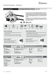
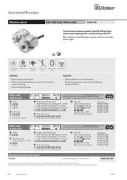
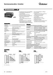
Electronic LED<br />
Preset Counter<br />
Type Series <strong>715</strong><br />
1. Description<br />
– 5 digit preset counter, 1 preset point, add./subtr.<br />
– bright LED display with 7.5 mm high characters<br />
– count and preset range –19999 to 99999, over- or <strong>und</strong>erflow<br />
without count loss up to 1 decade (will be indicated<br />
by flashing of the display with 1 Hz frequency)<br />
– programmable as impulse counter, frequency meter or<br />
timer<br />
– relay or optocoupler output (refer to ordering code)<br />
– prescaling factor 0.001...9.999<br />
– programming of count functions/operating parameters<br />
via the preset keys. During programming the display<br />
guides the user with text prompts.<br />
– programmable are:<br />
operating mode (output signal at zero or at preset<br />
point, with or without automatical reset)<br />
decimal point<br />
polarity of the inputs (NPN or PNP)<br />
input mode and factor<br />
output signal to be permanent or timed<br />
gate time when programmed as a frequency meter<br />
resolution when programmed as a timer (s, min or h)<br />
– supply voltage 230 VAC, 115 VAC or 11…30 VDC<br />
2. Inputs<br />
2.1 INP A, INP B<br />
Count inputs; max. count frequency 30 Hz or 10 kHz separately<br />
selectable for both inputs via programming switches<br />
C and D at the right side of the housing.<br />
INP A INP B<br />
Microswitch 30 Hz 10 kHz 30 Hz 10 kHz<br />
D ON OFF<br />
C ON OFF<br />
2.2 Gate<br />
Static input; no counting while this input is activated.<br />
If operated as a timer (only h, min and 0.1 min resolutions),<br />
the decimal point between the 4th and 5th decade flashes<br />
while gate input is not activated (operating indication).<br />
2.3 Reset<br />
Dynamic input; it is connected in parallel to the red reset<br />
key and sets the counter to zero (adding mode) or to the<br />
preset value (subtracting mode).<br />
2.4 Latch<br />
Static input for display stop. If this input is activated, the current<br />
count value will be retained until the latch input will be<br />
released again. Counting continues in the backgro<strong>und</strong>.<br />
2.5 Key<br />
Static keyboard lock input.<br />
While this input is activated, all front keys are locked.<br />
3. Output<br />
Relay with potentialfree change-over contact or optocoupler<br />
with open collector and emitter.<br />
When this output is activated, an annunciator (decimal<br />
point) will appear on the right of the first decade.<br />
For safety circuits the operation of the relay, resp. the optocoupler<br />
may be inversed in operating modes 1 and 2 (permanent<br />
signal only ) by programming 99.99 for duration of<br />
output signal . Thus the relay coil will be dead, resp. the optocoupler<br />
will be locked when reaching the preset point/<br />
zero.<br />
4. Programming procedure<br />
a. connect to supply voltage<br />
b. set microswitch “A” (right<br />
side of the housing) to “ON” for a<br />
short time. Display will show 1st<br />
menu point.<br />
c. select required functions via preset key 1, resp. enter<br />
data (prescaling factor, duration of timed signal, gate time)<br />
directly via preset keys 1–4.<br />
d. press preset key 5 to store selected function/enter data<br />
and to change over to next menu point.<br />
e. After programming the last menu point (permanent<br />
signal or timed signal) by pressing key 5, the routine will be<br />
left if microswitch “A” is set to “OFF”. If it is still set to “ON”,<br />
the programming routine will be passed through once<br />
again.<br />
5. Menus in detail<br />
5.1 Selection of basic function<br />
After microswitch “A” has been set to “ON” for a short time,<br />
one of the basic functions will be displayed:<br />
Programming Programming Programming<br />
routine routine routine<br />
Impulse Counter Timer Frequency Meter<br />
5.2.1 Programming routine Impulse Counter<br />
Operating mode 1:<br />
Output signal when count value �<br />
preset value<br />
Reset to zero<br />
Operating mode 2:<br />
Output signal when count value �<br />
zero<br />
Reset to preset value<br />
Operating mode 3:<br />
Timed signal when count value =<br />
preset value and automatical reset<br />
to zero.<br />
Reset to zero.<br />
Operating mode 4:<br />
Timed signal when count value =<br />
zero and automatical reset to preset<br />
value.<br />
Reset to preset value.<br />
Decimal point:<br />
only optical function!<br />
dP0 = no decimal point<br />
dP1 = 0000.0<br />
dP2 = 000.00<br />
dP3 = 00.000<br />
Polarity of the inputs:<br />
negative polarity (NPN),<br />
switching to 0 V<br />
positive polarity (PNP),<br />
switching to +24 V<br />
Input modes:<br />
E 1: INP A = count input<br />
INP B = count direction input<br />
E 2: INP A = count input, adding<br />
INP B = count input, subtracting<br />
E 3: Quadrature input<br />
INP A = count input 0°<br />
INP B = count input 90°<br />
E 4: same as E3 but with pulse<br />
doubling.<br />
Each pulse edge of INP A will<br />
be counted.<br />
Scaling factor:<br />
0.001...9.999<br />
to be entered via keys 1-4.<br />
Factor 0.000 won’t be accepted.<br />
Please note: In operating mode 2<br />
and 4 (output signal when count<br />
value = zero) the preset value has<br />
to be integerly divisible by the factor,<br />
otherwise the counter – when<br />
resetted – will be set to the following<br />
integer multiple of the factor.<br />
Duration of the output signal:<br />
00.00 = permanent signal in operating<br />
modes 1 and 2.<br />
0.01...99.98 s = timed signal in operating<br />
modes 1 to 4.<br />
99.99 s = permanent signal in operating<br />
modes 1 and 2, but with inverted<br />
operation of the relay or optocoupler<br />
(relay coil will be dead at<br />
preset value/zero, optocoupler will<br />
be locked).<br />
If microswitch “A” is set to “OFF”, the programming routine<br />
will be left now and the counter is ready to work.<br />
If microswitch “A” is still set to “ON”, the programming routine<br />
has to be passed through once again.<br />
5.2.2 Programming routine Timer<br />
Operating mode 1: Permanent<br />
signal when count value � preset<br />
value or timed signal when count<br />
value = preset value.<br />
Reset to zero<br />
Operating mode 2: Permanent<br />
signal when count value � zero or<br />
timed signal when count value =<br />
zero<br />
Reset to preset value<br />
Operating mode 3: Timed signal<br />
when count value = preset value<br />
and automatical reset to zero.<br />
Reset to zero<br />
Operating mode 4: Timed signal<br />
when count value = zero and automatical<br />
reset to preset value.<br />
Reset to preset value<br />
Unit of time:<br />
Timing in s, 0.1 s, 0.01 s or 0.001 s*<br />
Timing in min, 0.1 min, 0.01 min or<br />
0.001 min*<br />
Timing in h, 0.1 h, 0.01 h or<br />
0.001 h*<br />
*depending on position of decimal<br />
point<br />
Decimal point (resolution)<br />
dP0 = no decimal point<br />
dP1 = 0000.0<br />
dP2 = 000.00<br />
dP3 = 00.000<br />
Polarity of the inputs<br />
negative polarity (NPN), switching<br />
to 0 V<br />
positive polarity (PNP), switching to<br />
+24 V<br />
Duration of the output signal:<br />
00.00 = permanent signal in operating<br />
modes 1 and 2<br />
0.01... 99.98 s = timed signal in<br />
operating modes 1 to 4<br />
<strong>Fritz</strong> <strong>Kübler</strong> <strong>GmbH</strong> · <strong>Zähl</strong>- <strong>und</strong> <strong>Sensortechnik</strong> · P.O.Box 3440 · D-78023 VS-Schwenningen · Germany<br />
Phone: +49-7720-39 03-0 · Telefax: +49-7720-215 64 · E-Mail: sales@kuebler-gmbh.de · www.kuebler-gmbh.de
99.99 = permanent signal in operating modes 1 and 2, but<br />
with inverted operation of the relay or optocoupler (relay coil<br />
will be dead at preset value/zero, optocoupler will be<br />
locked).<br />
If microswitch "A" is set to "OFF", the programming routine<br />
will be left now and the counter is ready for operation.<br />
If microswitch "A" is still set to "ON", the programming routine<br />
has to be passed through once again.<br />
5.2.3 Programming routine Frequency Meter<br />
(output is activated when counter value �preset value)<br />
Gate Time = within this period the<br />
incoming pulses will be counted<br />
and displayed.<br />
Programmable range 0.01 s...<br />
99.99 s<br />
to be entered via keys 1 to 4.<br />
00.00 won't be accepted.<br />
Decimal point:<br />
only optical function.<br />
dP0 = no decimal point<br />
dP1 = 0000.0<br />
dP2 = 000.00<br />
dP3 = 00.000<br />
Polarity of the inputs:<br />
negative polarity (NPN),<br />
switching to 0 V<br />
positive polarity (PNP),<br />
switching to + 24 V<br />
Input modes:<br />
E1:<br />
INP A = count input<br />
INP B = count direction input<br />
E2:<br />
INP A = count input, adding<br />
INP B = count input, subtracting<br />
E3:<br />
Quadrature input<br />
INP A = count input 0°<br />
INP B = count input 90°<br />
E4:<br />
same as E3 but with pulse doubling.<br />
Each pulse edge of INP A will be<br />
counted.<br />
Scaling factor:<br />
0.001…9.999<br />
to be entered via keys 1-4.<br />
Factor 0.000 won't be accepted<br />
Duration of the output signal:<br />
00.00 = permanent signal in operating<br />
modes 1 and 2.<br />
0.01... 99.98 s = timed signal in operating<br />
modes 1 to 4.<br />
99.99 s = permanent signal in operating<br />
modes 1 and 2, but with inverted<br />
operation of the relay or optocoupler<br />
(relay coil will be dead at<br />
preset value/zero, optocoupler will<br />
be locked).<br />
If microswitch "A" is set to "OFF", the programming routine<br />
will be left now and the counter is ready to work.<br />
If microswitch "A" is still set to "ON", the programming routine<br />
has to be passed through once again.<br />
6. Programming of the Preset Value:<br />
After pressing one of the 5 preset keys,<br />
the preset value will be displayed. This<br />
value can be changed via the preset keys<br />
(one key for each digit).<br />
4 seconds after release of the last key<br />
pressed the preset value will disappear<br />
from the display and the count value will<br />
be shown again.<br />
6.1 Characteristics of 5th decade:<br />
Preset value +9XXXX<br />
Preset value –XXXX<br />
Preset value –1XXXX<br />
Preset value +0XXXX<br />
7. Examples for application<br />
connections:<br />
Count pulses from contact closure<br />
(programmed polarity PNP)<br />
Count pulses from a light barrier<br />
Count pulses from a shaft encoder<br />
8. Connections<br />
Plug connection X1<br />
�not when<br />
programmed<br />
as a timer<br />
Terminal<br />
No. 115/230 VAC version 11…30 VDC version<br />
1 + 24 VDC<br />
transmitter voltage<br />
—<br />
2 0 VDC (GND) —<br />
3 Relay output common contact (C)<br />
Optocoupler output emitter<br />
4 Relay output normally open contact (NO)<br />
5 Relay output normally closed contact (NC)<br />
Optocoupler output collector<br />
6 115 VAC / 230 VAC +11…30 VDC<br />
7 115 VAC / 230 VAC 0 VDC (GND)<br />
Please note: If permanent signal = 99.99 s (inverted operation<br />
of relay resp. optocoupler), the connections of terminal<br />
4 and 5 are as follows:<br />
Terminal<br />
No. AC- and DC version<br />
4 Relay output normally closed contact (NC)<br />
5 Relay output normally open contact (NO)<br />
Plug connection X2<br />
Terminal No. Designation Function<br />
1 INP A count input A<br />
2 INP B count input B<br />
3 GATE gate input<br />
4 RESET reset input<br />
5 LATCH display stop input<br />
6 KEY keyboard lock input<br />
9. Technical Data<br />
Supply voltage:<br />
230 VAC, 115 VAC, max. 4 VA<br />
or 11…30 VDC, max. 0.1 A<br />
Display: 5 digit 7 segment red LED display<br />
with 7.5 mm high characters<br />
Polarity of input signals:<br />
programmable, all inputs in common<br />
Input resistance:<br />
approx. 10 kOhm<br />
Count frequency:<br />
via DIL switches separately selectable for<br />
INP A and INP B<br />
30 Hz<br />
10 kHz (7.5 kHz in input mode E4)<br />
automatical reset 1 kHz without count losses<br />
(600 Hz in input mode E4)<br />
Min. pulse length of the control inputs:<br />
5 ms<br />
Input sensitivity:<br />
AC supply voltages<br />
Log “0”: 0… 4 VDC<br />
Log “1”: 12…30 VDC<br />
DC supply voltages Ub<br />
Log “0”: 0…0.2 x Ub<br />
Log “1”: 0.6 x Ub…30 VDC<br />
Pulse shape: variable (Schmitt Trigger characteristic)<br />
Output: relay with potentialfree change-over contact<br />
switching voltage max. 250 VAC / 300 VDC<br />
switching current max. 3 A<br />
switching current for DC min. 30 mA<br />
switching performance max. 50 W for DC<br />
max. 2000 VA for AC<br />
or<br />
optocoupler with open collector and emitter<br />
switching performance: 30 VDC / 15 mA<br />
Ucesat at Ic = 15 mA: max. 2.0 V<br />
Ucesat at Ic = 5 mA: max. 0.4 V<br />
Responding time of output:<br />
relay: approx. 6 ms<br />
optocoupler: approx. 1 ms<br />
Data retention:<br />
min. 10 years or10 6 memory cycles<br />
Transmitter voltage:<br />
24 VDC –40%/+15%, 80 mA unstabilized<br />
for AC-versions<br />
Noise immunity:<br />
EN 55011 class B and prEN 50082-2<br />
Ambient temperature:<br />
0…50°C<br />
Storage temperature:<br />
–25°C…+70°C<br />
Weight: approx. 240 g (AC-version with relay)<br />
Protection: IP 54 (front)<br />
Colour of housing:<br />
black<br />
10. Ordering Code<br />
6.<strong>715</strong>.01X.X00<br />
Supply voltage<br />
0 = 230 VAC<br />
1 = 115 VAC<br />
3 = 11…30 VDC<br />
Output<br />
0 = relay<br />
1 = optocoupler<br />
<strong>Fritz</strong> <strong>Kübler</strong> <strong>GmbH</strong> · <strong>Zähl</strong>- <strong>und</strong> <strong>Sensortechnik</strong> · P.O.Box 3440 · D-78023 VS-Schwenningen · Germany<br />
Phone: +49-7720-39 03-0 · Telefax: +49-7720-215 64 · E-Mail: sales@kuebler-gmbh.de · www.kuebler-gmbh.de<br />
– Subject to changes without prior notice –