MANTIS Redux - Stryker
MANTIS Redux - Stryker
MANTIS Redux - Stryker

Create successful ePaper yourself
Turn your PDF publications into a flip-book with our unique Google optimized e-Paper software.
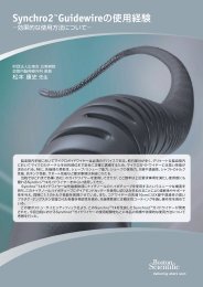
<strong>MANTIS</strong> <strong>Redux</strong><br />
Surgical Technique<br />
LITe<br />
Less Invasive Technologies<br />
• True percutaneous screw and<br />
rod system<br />
• Direct visualization<br />
• Precise rod contouring allows<br />
multiple levels
<strong>MANTIS</strong> <strong>Redux</strong><br />
Surgical Technique<br />
Table of Contents<br />
Acknowledgments . . . . . . . . . . . . . . . . . . . . . . . . . . . . . . . . . . . . . . . . . . . . . . . . . . . . . . . . . .4<br />
Introduction . . . . . . . . . . . . . . . . . . . . . . . . . . . . . . . . . . . . . . . . . . . . . . . . . . . . . . . . . . . . . . .4<br />
Key Design Features . . . . . . . . . . . . . . . . . . . . . . . . . . . . . . . . . . . . . . . . . . . . . . . . . . . . . . . .5<br />
Markings . . . . . . . . . . . . . . . . . . . . . . . . . . . . . . . . . . . . . . . . . . . . . . . . . . . . . . . . . . . . . . . . . .6<br />
Patient Positioning . . . . . . . . . . . . . . . . . . . . . . . . . . . . . . . . . . . . . . . . . . . . . . . . . . . . . . . . .6<br />
K-Wire Insertion . . . . . . . . . . . . . . . . . . . . . . . . . . . . . . . . . . . . . . . . . . . . . . . . . . . . . . . . . . .8<br />
Dilation . . . . . . . . . . . . . . . . . . . . . . . . . . . . . . . . . . . . . . . . . . . . . . . . . . . . . . . . . . . . . . . . . .12<br />
Pedicle Preparation . . . . . . . . . . . . . . . . . . . . . . . . . . . . . . . . . . . . . . . . . . . . . . . . . . . . . . . .14<br />
Screw Insertion . . . . . . . . . . . . . . . . . . . . . . . . . . . . . . . . . . . . . . . . . . . . . . . . . . . . . . . . . . .16<br />
To assemble the Polyaxial Screwdriver: . . . . . . . . . . . . . . . . . . . . . . . . . . . . . . . . . . . . . .19<br />
Screw Adjustment . . . . . . . . . . . . . . . . . . . . . . . . . . . . . . . . . . . . . . . . . . . . . . . . . . . . . . . . .22<br />
Screw Alignment . . . . . . . . . . . . . . . . . . . . . . . . . . . . . . . . . . . . . . . . . . . . . . . . . . . . . . . . . .22<br />
Rod Insertion . . . . . . . . . . . . . . . . . . . . . . . . . . . . . . . . . . . . . . . . . . . . . . . . . . . . . . . . . . . . .24<br />
Blocker Inserter . . . . . . . . . . . . . . . . . . . . . . . . . . . . . . . . . . . . . . . . . . . . . . . . . . . . . . . . . . .26<br />
Compression and Distraction . . . . . . . . . . . . . . . . . . . . . . . . . . . . . . . . . . . . . . . . . . . . . . .26<br />
Construct Tightening . . . . . . . . . . . . . . . . . . . . . . . . . . . . . . . . . . . . . . . . . . . . . . . . . . . . . .28<br />
Closure . . . . . . . . . . . . . . . . . . . . . . . . . . . . . . . . . . . . . . . . . . . . . . . . . . . . . . . . . . . . . . . . . . .30<br />
Catalog . . . . . . . . . . . . . . . . . . . . . . . . . . . . . . . . . . . . . . . . . . . . . . . . . . . . . . . . . . . . . . . . . . .32<br />
Indications . . . . . . . . . . . . . . . . . . . . . . . . . . . . . . . . . . . . . . . . . . . . . . . . . . . . . . . . . . . . . . . .34
<strong>MANTIS</strong> <strong>Redux</strong><br />
Surgical Technique<br />
Introduction<br />
Acknowledgments<br />
<strong>Stryker</strong> Spine wishes to thank the following physicians for<br />
authoring this surgical technique.<br />
Dan Cohen, MD<br />
Nils Hansen-Algenstaedt, MD<br />
Terrence Julien, MD<br />
Reginald Knight, MD<br />
Jeffrey Roh, MD<br />
One primary objective of <strong>Stryker</strong> Spine's Less Invasive Technologies (LITe) is to<br />
replicate the clinical results of the corresponding open procedure.<br />
At the moment there is insufficient data to show that minimally invasive spine<br />
surgery provides any short and long term benefit to patients when compared to<br />
traditional spine surgery.<br />
Important<br />
This Surgical Technique sets forth detailed, recommended procedures for using the<br />
<strong>MANTIS</strong> <strong>Redux</strong> Spinal System. It offers guidandce that you should heed but as with<br />
any such technical guide, each surgeon must consider the particular needs of each<br />
patient and make appropriate adjustments when necessary and as required.<br />
Always refer to the package insert, product label and/or instructions before using any<br />
<strong>Stryker</strong> implant or instrument.<br />
Note: No acid or alkaline solvents should be used in the cleaning of anodized<br />
components.<br />
Note: Upon the completion of each surgical procedure, use adequate suction and<br />
irrigation to ensure the removal of any existing non-implantable materials.<br />
Note: This is intended as a guide only. There are multiple techniques, and as with<br />
any surgical procedure, a surgeon should be thoroughly trained before proceeding.
Key Design Features<br />
Device Comments<br />
Titanium Polyaxial<br />
Reduction Screws<br />
1) 4.5mm x 25-45mm<br />
2) 5.5mm x 30-55mm<br />
3) 6.5mm x 30-60mm<br />
Xia 3 Bone Screw Cannulated Xia 3 design offers a much more rigid<br />
connection to the screwdriver.<br />
Intraoperative Rod<br />
Options<br />
Accepts Titanium and Vitallium rods in 5.5mm and<br />
6.0mm diameters.<br />
Low Profile The tulip is lower profile than the <strong>MANTIS</strong> screwhead<br />
when broken off.<br />
Spondy Reduction The surgeon should be able reduce a spondy with the<br />
implant.<br />
Guaranteed Rod<br />
Seating<br />
Reduction Tab<br />
Removal Instrument<br />
Provides for a larger margin of error when introducing<br />
the rod. The surgeon can use the implant to fully seat<br />
the rod every time.<br />
Self guiding instrument that can be used to break off<br />
and remove tabs percutaneously.
Patient<br />
Positioning<br />
6<br />
<strong>MANTIS</strong> <strong>Redux</strong><br />
Surgical Technique<br />
Figure 1<br />
Figure 2A<br />
Figure 2B<br />
Patient Positioning<br />
<strong>MANTIS</strong> <strong>Redux</strong> can be used under local, epidural,<br />
spinal or general anesthesia. General anesthesia is<br />
commonly used since it is the most comfortable for the<br />
patient and allows immediate postoperative<br />
neurological assessment.<br />
> The patient is prepped and draped in the usual<br />
sterile manner for posterior fusion with pedicle<br />
screw fixation.<br />
Markings<br />
> Using A/P imaging, place the K-Wire transversly<br />
across the mid-line of the cephalad pedicles.
Repeat for additional pedicles.<br />
Figure 3A<br />
Figure 3B<br />
Instrument Bar<br />
Sharp 48230230<br />
Blunt 48230231<br />
K-Wire<br />
Patient<br />
Positioning<br />
7
Patient<br />
Positioning<br />
K-Wire<br />
Insertion<br />
8<br />
<strong>MANTIS</strong> <strong>Redux</strong><br />
Surgical Technique<br />
Figure 4<br />
Figure 5<br />
Figure 6<br />
Carefully determine the appropriate entry point and<br />
trajectory for the <strong>MANTIS</strong> <strong>Redux</strong> Screw.<br />
> For pedicle screws, the entry point is approximately<br />
4cm off mid-line with a more lateral trajectory.<br />
> Incise the skin. A fascial incision may be done to<br />
make tissue dilation easier.<br />
Note: If tissue dilation is difficult, increase the fascial<br />
incision.<br />
K-Wire Insertion<br />
> Insert the Jam Shidi through the skin incision to the<br />
intersection of the facet and transverse process.<br />
> Confirm that the appropriate pedicle starting place<br />
has been determined using both A/P and lateral<br />
images.<br />
Note: The diameter of the <strong>MANTIS</strong> K-Wire is 1.3mm.<br />
Note: The Radius K-Wire is not compatible with the<br />
<strong>MANTIS</strong> Spinal System.<br />
> Use the Jam Shidi needle to gain access to the<br />
pedicle.<br />
> After placing the Jam Shidi at the intersection of the<br />
facet and the transverse process, the needle may be<br />
advanced partially through the pedicle using the<br />
Slap Hammer.
Figure 7<br />
> As the pedicle is navigated with the Jam Shidi, it<br />
should approach the medial wall of the pedicle on<br />
the A/P view and should approach the base of the<br />
pedicle on the lateral view.<br />
Figure 8<br />
> When the needle reaches the medial wall on the A/P<br />
view, verification needs to be performed in the<br />
lateral view to ensure that the needle is past the base<br />
of the pedicle.<br />
Instrument Bar<br />
10 Gauge, 9 inch 48237110<br />
10 Gauge, 5 inch 48237105<br />
11 Gauge, 5 inch 48237115<br />
13 Gauge, 5 inch 48237135<br />
Jam Shidi<br />
48237120<br />
Slap Hammer<br />
Sharp 48230230<br />
Blunt 48230231<br />
K-Wire<br />
Patient<br />
Positioning<br />
K-Wire<br />
Insertion<br />
9
K-Wire<br />
Insertion<br />
10<br />
<strong>MANTIS</strong> <strong>Redux</strong><br />
Surgical Technique<br />
Figure 9<br />
Figure 10<br />
Figure 11<br />
> Remove the inner trocar of the Jam Shidi.<br />
> The removal of the Jam Shidi inner trocar allows the<br />
K-Wire to be inserted into the pedicle.<br />
> Caution should be practiced with regard to the<br />
position of the K-Wire in order to avoid the<br />
advancement of the K-Wire.<br />
Note: The K-Wire is a single use instrument.<br />
Note: The Radius K-Wire is not compatible with<br />
<strong>MANTIS</strong> products.<br />
Use the K-Wire Guide Tube to prevent the K-Wire<br />
from bending or moving during insertion.<br />
> Place the K-Wire Guide Tube over the K-Wire and<br />
dock on the Jam Shidi.<br />
> Use the Slap Hammer to impact the K-Wire.
Figure 12<br />
> Once the K-Wire is inserted, remove the outer shaft<br />
of the Jam Shidi.<br />
> Hold the K-Wire in position when removing the<br />
Jam Shidi.<br />
Instrument Bar<br />
10 Gauge, 9 inch 48237110<br />
10 Gauge, 5 inch 48237105<br />
11 Gauge, 5 inch 48237115<br />
13 Gauge, 5 inch 48237135<br />
Jam Shidi<br />
Sharp 48230230<br />
Blunt 48230231<br />
K-Wire<br />
48230235<br />
K-Wire Guide Tube<br />
48237120<br />
Slap Hammer<br />
K-Wire<br />
Insertion<br />
11
Dilation<br />
12<br />
<strong>MANTIS</strong> <strong>Redux</strong><br />
Surgical Technique<br />
Figure 13<br />
Figure 14<br />
Figure 15<br />
Dilation<br />
> Place the Slim Dilator over the K-Wire, through the<br />
incision.<br />
> Advance the Slim Dilator, over the K-Wire, through<br />
the tissue twisting clockwise while directing it<br />
toward the pedicle.<br />
> The Slim Dilator is advanced through the<br />
lumbodorsal fascia.<br />
> Location of the Slim Dilator is confirmed using<br />
imaging.<br />
> Note the depth marking of the Slim Dilator in<br />
relation to the skin.<br />
Note: Feel, fluoroscopy, anatomical knowledge, review<br />
of preoperative images and partial visualization may all<br />
contribute towards desired instrument placement<br />
accuracy.<br />
Note: The dilators have depth markings laser etched<br />
which correlate to the blade lengths.<br />
> Choose a <strong>Redux</strong> Blade length based on where the<br />
top of the skin meets the Slim Dilator.<br />
Note: If the skin is exactly on the marking on the Slim<br />
Dilator, choose the longer blade size.<br />
> Sequentially slide Dilator 2, Dilator 3 and the<br />
Hollow Dilator over the Slim Dilator to sequentially<br />
penetrate and gently dissect soft tissue down to the<br />
pedicle.<br />
> Twist the dilators clockwise during insertion to<br />
engage the thread features.
Remove the initial dilators after inserting the<br />
Hollow Dilator.<br />
Figure 16<br />
> The Hollow Dilator remains in place as the working<br />
channel for pedicle preparation.<br />
Instrument Bar<br />
48280105<br />
Slim Dilator<br />
Sharp 48230230<br />
Blunt 48230231<br />
K-Wire<br />
Size 1 3-5cm 48289035<br />
Size 2 5-7cm 48289057<br />
Size 3 7-9cm 48289079<br />
Size 4 9-11cm 48289911<br />
Size 5 11-13cm 48289113<br />
<strong>Redux</strong> Blade<br />
48280106<br />
Dilator 2<br />
48280107<br />
Dilator 3<br />
48280102<br />
Hollow Dilator<br />
Dilation<br />
13
Dilation<br />
14<br />
<strong>MANTIS</strong> <strong>Redux</strong><br />
Surgical Technique<br />
Figure 17<br />
Figure 18<br />
Figure 19<br />
Pedicle Preparation<br />
> With the Hollow Dilator still in place, prepare the<br />
pedicle by placing the Cannulated Modular Awl<br />
over the K-Wire and impact into the pedicle with a<br />
twisting motion.<br />
> Hold the K-Wire in position when removing the<br />
awl.<br />
> Use the cannulation of the Slap Hammer to impact<br />
the awl.<br />
Note: The awl has a stop at 12mm.<br />
> If the bone is too hard, the appropriate tap may be<br />
used to prepare the pedicle.<br />
> The Cannulated Modular Taps are calibrated with<br />
the Tap Sleeve and laser etched with 5mm intervals<br />
to help indicate the depth at which the tap has been<br />
inserted. This is designed to help determine proper<br />
screw length.<br />
Note: The length of the taps thread is 25mm.<br />
Note: The Cannulated Modular Taps are calibrated with<br />
the <strong>MANTIS</strong> Tap Sleeve. This measurement technique<br />
will not work with the Xia Precision Tap Sleeve, as it is<br />
shorter.<br />
> As an instrument advances into the pedicle, the<br />
proximal end of the instrument will move relative to<br />
the markings on the K-Wire. If this does not occur,<br />
the surgeon should stop and fluoroscopy should be<br />
used to verify the position of the K-Wire.<br />
Note: 1cm interval markings on the K-Wire provide the<br />
cannulated instruments change in depth in the pedicle.
Figure 20<br />
> Check pedicle depth with either fluoroscopy or read the depth<br />
from the Tap Sleeve as it moves along the proximal edge of the<br />
tap. There are markings at 30mm, 40mm and 50mm.<br />
Note: The Tap Sleeve is made of radiolucent Ultem Poly Ether Imide.<br />
Note: Slide the Tap Sleeve proximal to the tap shaft to engage the<br />
friction fit. This prevents the Tap Sleeve from sliding off the tap.<br />
Figure 21<br />
> Hold the K-Wire in position when removing the tap.<br />
The Hollow Dilator can now be removed. Hold the K-Wire in<br />
position when removing the Hollow Dilator.<br />
Instrument Bar<br />
48280102<br />
Hollow Dilator<br />
48281164<br />
Cannulated Modular Awl<br />
Sharp 48230230<br />
Blunt 48230231<br />
K-Wire<br />
48237120<br />
Slap Hammer<br />
4.5mm 48281161<br />
5.5mm 48281165<br />
6.5mm 48281166<br />
7.5mm 48281167<br />
Cannulated Modular Tap<br />
48281315<br />
Tap Sleeve<br />
Dilation<br />
15
Screw<br />
Insertion<br />
16<br />
<strong>MANTIS</strong> <strong>Redux</strong><br />
Surgical Technique<br />
Figure 22<br />
Figure 23<br />
Figure 24<br />
Screw Insertion<br />
With the pedicle pathways prepared and proper screw<br />
length and diameter selected, the screw is prepared for<br />
insertion.<br />
Assemble each pair of <strong>Redux</strong> Blades into the <strong>Redux</strong><br />
Screw.<br />
> Orient the screw so that the tulip posts are pointing<br />
up.<br />
> Insert the appropriate size blade into each side of<br />
the tulip posts and spread apart.<br />
Note: Blade size is chosen from the measurement taken<br />
from the dilator.<br />
> Orient the Sliding Ring with the flat side down.<br />
> Insert the blades through the bottom of the Sliding<br />
Ring.<br />
> Repeat this process for additional screws.<br />
Note: If a lower profile is desired, the Slim Ring may be<br />
used as an alternative to the Sliding Ring.<br />
Note: The <strong>MANTIS</strong> <strong>Redux</strong> Blades are not compatible<br />
with the <strong>MANTIS</strong> Persuader.
The <strong>MANTIS</strong> <strong>Redux</strong> Screws have 3 cutting<br />
flutes to allow a surgeon to eliminate the<br />
tapping step. The screws may be inserted<br />
immediately after the K-Wire is<br />
introduced. However, in most cases,<br />
tapping is recommended.<br />
Figure 25<br />
The 6 point star Screw head is designed:<br />
> For faster and intuitive engagement with the Screwdriver.<br />
> To prevent screwhead stripping.<br />
> For reengagement for screw adjustments.<br />
Instrument Bar<br />
See Catalog<br />
Long Arm PA Screw<br />
Size 1 3-5cm 48289035<br />
Size 2 5-7cm 48289057<br />
Size 3 7-9cm 48289079<br />
Size 4 9-11cm 48289911<br />
Size 5 11-13cm 48289113<br />
<strong>Redux</strong> Blade<br />
48281201<br />
Slim Ring<br />
Sharp 48230230<br />
Blunt 48230231<br />
K-Wire<br />
Screw<br />
Insertion<br />
17
Screw<br />
Insertion<br />
18<br />
<strong>MANTIS</strong> <strong>Redux</strong><br />
Surgical Technique<br />
T-Handle<br />
T-Handle Ratchet<br />
Round Handle<br />
Round Handle Ratchet<br />
Inner Shaft<br />
Outer Shaft<br />
Sleeve for<br />
Screwdriver<br />
The Polyaxial Screwdriver provides a rigid connection<br />
between the screws and the screwdriver.<br />
A primary design goal of the <strong>MANTIS</strong> <strong>Redux</strong> system is<br />
to improve the connection between the screwdriver and<br />
screws. The screwdriver is improved to decrease toggle<br />
at 2 integral points of connection:<br />
> Screwdriver to Screw Interface<br />
> Screwdriver to Shaft Interface<br />
The locking feature provides tactile, visual and audible<br />
confirmation that the screwdriver is securely locked.<br />
The Polyaxial Screwdriver can be connected to the<br />
following Handles:<br />
48289200 T-Handle Ratchet<br />
48289300 Round Handle Ratchet<br />
48289205 T-Handle Non-Ratchet<br />
48289305 Round Handle Non-Ratchet
Figure 26<br />
To assemble the Polyaxial Screwdriver:<br />
Step 1<br />
Press the “UNLOCK” button on the outer shaft.<br />
Figure 27<br />
Step 2<br />
Insert the Shaft for Polyaxial Screwdriver down the<br />
outer shaft.<br />
Figure 28<br />
Step 3<br />
Slide the sleeve for the screwdriver up the inner shaft. Verify the<br />
sleeve for screwdriver is completely bottomed out.<br />
Instrument Bar<br />
48289310<br />
Polyaxial Screwdriver<br />
48289311<br />
Shaft for Polyaxial Screwdriver<br />
48289205<br />
T-Handle Non-Ratchet<br />
48289200<br />
T-Handle Ratchet<br />
48289305<br />
Round Handle Non-Ratchet<br />
48289300<br />
Round Handle Ratchet<br />
Screw<br />
Insertion<br />
19
Screw<br />
Insertion<br />
20<br />
<strong>MANTIS</strong> <strong>Redux</strong><br />
Surgical Technique<br />
Figure 29<br />
Figure 30<br />
Figure 31<br />
Figure 32<br />
Step 4<br />
Align the tabs and fully insert the quick connect<br />
mechanism into the shaft.<br />
Step 5<br />
Hold the screw by the threads and engage the tabs on<br />
the inner shaft onto the saddle of the screw head.<br />
Step 6<br />
Fully seat the inner shaft into the screwhead. Turn the<br />
outer shaft clockwise using the “LOCK” button until<br />
the threads are fully engaged.<br />
Step 7 (Optional)<br />
If the ratchet sound is not present, confirm locking by<br />
pressing the “LOCK” Button.
Figure 33<br />
Place the screwdriver over the K-Wire and insert into<br />
the pedicle.<br />
Figure 34<br />
After driving the screw into the pedicle, remove the<br />
K-Wire to prevent it from advancing.<br />
Instrument Bar<br />
48289310<br />
Polyaxial Screwdriver<br />
48289311<br />
Shaft for Polyaxial Screwdriver<br />
Sharp 48230230<br />
Blunt 48230231<br />
K-Wire<br />
Screw<br />
Insertion<br />
21
Screw<br />
Insertion<br />
22<br />
<strong>MANTIS</strong> <strong>Redux</strong><br />
Surgical Technique<br />
Figure 35<br />
Figure 36<br />
Figure 37<br />
Be certain that the screw is not inserted too far. If the<br />
polyaxial head of the screw is driven to forcefully<br />
against bone, it will lose its polyaxial capabilities<br />
making it difficult to connect the assemblies during<br />
subsequent steps.<br />
Note: Use imaging and monitoring, as preferred, for<br />
added information during bone screw insertion.<br />
To disengage the screwdriver from the screw, press and<br />
release the “UNLOCK” button. Rotate outer shaft<br />
counter-clockwise while firmly holding the handle.<br />
Repeat the process for additional screws.<br />
Screw Alignment<br />
> Insert the Rod Contouring Shafts into the screw<br />
head. The Rod Contouring Shafts should be firmly<br />
seated into the screw heads.<br />
Note: The laser markings on the Rod Contouring Shafts<br />
correspond to the blades to indicate that the shafts are<br />
properly seated.<br />
Note: It is recommended to use the Rod Contouring<br />
Shafts when manipulating the screw heads.<br />
Note: The polyaxial bone screws may provisionally lock<br />
upon insertion. With the Rod Contouring Shafts in<br />
place, rotate the blades to unlock the heads before<br />
introducing the rod.<br />
Screw Adjustment<br />
The screw heights may be adjusted as needed using the<br />
Poly Adjustment Driver. Use fluoroscopic images to<br />
confirm.<br />
The Poly Adjustment Driver can be inserted through<br />
the cannulas of the Rod Contouring Shafts.
Figure 38<br />
> Align the Rod Contouring Shafts so that they are parallel.<br />
> Attach the Rod Contouring Linkage to the Rod Contouring<br />
Shafts. As needed, attach additional Rod Contouring Linkages,<br />
alternating sides.<br />
Figure 39<br />
> Lock the Rod Contouring Linkages into place by twisting the<br />
wing nut clockwise. The indicator should be flush on top.<br />
Note: By locking the Rod Contouring Shafts in parallel, the top of<br />
the shafts reproduce the relative spacing of the screws above the skin.<br />
Note: If the distance between screws is too great, use the Extended<br />
Rod Contouring Linkage<br />
Instrument Bar<br />
48284030<br />
Rod Contouring Shaft<br />
48289733<br />
Poly Adjustment Driver<br />
48284035<br />
Rod Contouring Linkage<br />
48284036<br />
Extended Rod Contouring Linkage<br />
Screw<br />
Insertion<br />
23
Rod<br />
Insertion<br />
24<br />
<strong>MANTIS</strong> <strong>Redux</strong><br />
Surgical Technique<br />
Figure 40<br />
Figure 41<br />
Figure 42<br />
Rod Insertion<br />
> Attach the appropriate <strong>MANTIS</strong> Rod to the Rod<br />
Inserter. Lock the rod into position by twisting the<br />
knob clockwise.<br />
Note: Match the laser mark on the rod with the slot on<br />
the Rod Inserter during assembly to ensure that the rod<br />
and Rod Inserter are aligned in the same plane.<br />
Warning: Do not tighten the Rod Inserter without a<br />
rod in place. Tightening without a rod in place may<br />
damage the Rod Inserter.<br />
Note: In order to insert a 5.5mm rod, the Rod Gripper<br />
should be used.<br />
Note: The Rod Inserter is laser marked along the shaft<br />
to indicate when the rod is locked in place.<br />
> Insert the rod percutaneously from either the<br />
cephalad or caudal side through the blades. Using<br />
direct visualization, guide the rod through each pair<br />
of blades.<br />
Note: The rod is to be inserted from the open side of<br />
the Sliding Ring.
Figure 43<br />
Note: The rod should overhang the screw by 4mm.<br />
Figure 44<br />
> The Rod Gripper may be used for adjustment of the rod.<br />
> Insert the Rod Gripper down the blades. Squeeze the<br />
handle to engage the rod.<br />
> Manipulate the rod as needed.<br />
Instrument Bar<br />
48284053<br />
Rod Inserter<br />
48281201<br />
Slim Ring<br />
48284055<br />
Rod Gripper<br />
Rod<br />
Insertion<br />
25
Blocker<br />
Inserter<br />
Compression<br />
and Distraction<br />
26<br />
<strong>MANTIS</strong> <strong>Redux</strong><br />
Surgical Technique<br />
Figure 45<br />
Figure 46<br />
Figure 47<br />
Blocker Inserter<br />
> Use the Counter Torque Tube as an insertion tube<br />
to facilitate alignment of the Blocker with the tulip.<br />
Note: The laser markings on the Counter Torque Tube<br />
correspond to the blades to indicate that the instrument<br />
is properly seated.<br />
> Slide the Blocker Inserter and Blocker through the<br />
Counter Torque Tube and into the screw head.<br />
Note: It is recommended to insert the most distal<br />
Blocker first.<br />
> Rotate the Blocker clockwise to seat the blocker.<br />
> Repeat for other bone screws.<br />
Note: The Blocker Inserter is not intended to be used<br />
for final tightening.<br />
> Once the rod is sufficiently captured in the screws,<br />
detach the Rod Inserter from the rod by turning the<br />
knob on the Rod Inserter counter-clockwise.<br />
Note: The Rod Inserter Inner Shaft is laser marked to<br />
indicate a locked and unlocked position.<br />
Note: The Rod Inserter is to be removed along the axis<br />
of the rod.<br />
Compression and Distraction<br />
> To achieve compression and distraction, insert the<br />
Compression & Distraction Shaft and<br />
Compression & Distraction Hinge through the<br />
blades and into the screw heads.<br />
> Note the laser marking on the shafts to ensure that<br />
the shafts are fully seated.<br />
Note: The Compression & Distraction Shaft and Hinge<br />
are to be oriented so that the eyelets are located on the<br />
outside.
Figure 48<br />
> Mate the tops of the Compression & Distraction<br />
Shaft and Hinge using the connecting feature.<br />
Figure 49<br />
> To distract, insert the Distractor into the eyelets of<br />
the Compression & Distraction Shaft and Hinge.<br />
Squeeze the Distractor to apply the appropriate<br />
distraction.<br />
Instrument Bar<br />
48289480<br />
Counter Torque Tube<br />
48289999<br />
LITe Blocker<br />
48287008<br />
Blocker Inserter<br />
48284053<br />
Rod Inserter<br />
48289077<br />
Compression & Distraction Shaft<br />
48289078<br />
Compression & Distraction Hinge<br />
Blocker<br />
Inserter<br />
Compression<br />
and Distraction<br />
27
Compression<br />
and Distraction<br />
Construct<br />
Tightening<br />
Tab<br />
Removal<br />
28<br />
<strong>MANTIS</strong> <strong>Redux</strong><br />
Surgical Technique<br />
Figure 50<br />
Figure 51<br />
> To compress, insert the Compressor into the eyelets<br />
of the Compression & Distraction Shaft and Hinge.<br />
Squeeze the Compressor to apply the appropriate<br />
distraction.<br />
Note: The Compression & Distraction Shaft and Hinge<br />
are cannulated to allow for Blocker introduction.<br />
Construct Tightening<br />
Once the correction procedures have been carried out<br />
and the spine is fixed in satisfactory position, the final<br />
tightening of the Blocker is done by utilizing the<br />
Counter Torque Tube and Torque Wrench.<br />
> Dock the Counter Torque Tube on the screw.<br />
> Note the depth markings on the Counter Torque<br />
Tube to ensure that it is fully engaged with the<br />
screw.<br />
> Insert the Torque Wrench into the Counter Torque<br />
Tube to engage the Blocker.<br />
> Line up the two arrows on the Torque Wrench to<br />
achieve the best possible torque of 12Nm for final<br />
tightening of the implants.<br />
Note: The Counter Torque Tube must be used for final<br />
tightening. The Counter Torque Tube performs two<br />
important functions:<br />
1. It allows the Torque Wrench to align with the axis<br />
of the tightening axis.<br />
2. It allows one to apply the torque needed to lock<br />
the implant assembly without applying the torque<br />
to the rest of the construct.<br />
Note: If the Counter Torque Tube cannot be easily<br />
removed from the implant head, the rod may not be<br />
fully seated.<br />
Note: The Xia Torque Wrench is not compatible with<br />
<strong>MANTIS</strong> <strong>Redux</strong>.
Tab Removal<br />
Figure 52<br />
Once final tightening has taken place, the <strong>MANTIS</strong> <strong>Redux</strong> screw<br />
tabs are broken off. A snap line allows a clean and easy break.<br />
> Remove the Sliding Ring from the blades by pulling up.<br />
Figure 53<br />
Slide the Tab Breaker over the blades and over the<br />
<strong>MANTIS</strong> <strong>Redux</strong> screw tabs.<br />
Instrument Bar<br />
48289077<br />
Compression & Distraction Shaft<br />
48289078<br />
Compression & Distraction Hinge<br />
48284070<br />
Distractor<br />
48284075<br />
Compressor<br />
48289480<br />
Counter Torque Tube<br />
48287028<br />
Torque Wrench<br />
48281201<br />
Slim Ring<br />
48289100<br />
Tab Breaker<br />
Compression<br />
and Distraction<br />
Construct<br />
Tightening<br />
Tab<br />
Removal<br />
29
Tab<br />
Removal<br />
30<br />
<strong>MANTIS</strong> <strong>Redux</strong><br />
Surgical Technique<br />
1 2<br />
Figure 54<br />
Figure 55<br />
> The Tab Breaker is rocked in a back and forth<br />
motion to break the screw tab.<br />
> The Tab Breaker will retain both the blades and<br />
the screw tab.<br />
> The Tab Breaker is removed from the incision.<br />
> Remove the blade and screw tab from the Tab<br />
Breaker.<br />
> Repeat for all other screws.<br />
Note: The tab breaker has a large window to hold the<br />
blade during removal.
Closure<br />
Examine the site for bleeding.<br />
Figure 56<br />
If accessible, close the fascia with one or two interrupted<br />
sutures. The subcutaneous tissue is closed in an inverted<br />
manner. A subcuticular closure is performed. Cover the<br />
skin edge with clear waterproof dressing.<br />
Instrument Bar<br />
48289100<br />
Tab Breaker<br />
Tab<br />
Removal<br />
31
Catalog<br />
32<br />
<strong>MANTIS</strong> <strong>Redux</strong><br />
Surgical Technique<br />
Catalog # Description<br />
Implant Part Numbers<br />
48289425 Long Arm PA Screw 4.5mm x 25mm<br />
48289430 Long Arm PA Screw 4.5mm x 30mm<br />
48289435 Long Arm PA Screw 4.5mm x 35mm<br />
48289440 Long Arm PA Screw 4.5mm x 40mm<br />
48289445 Long Arm PA Screw 4.5mm x 45mm<br />
48289530 Long Arm PA Screw 5.5mm x 30mm<br />
48289535 Long Arm PA Screw 5.5mm x 35mm<br />
48289540 Long Arm PA Screw 5.5mm x 40mm<br />
48289545 Long Arm PA Screw 5.5mm x 45mm<br />
48289550 Long Arm PA Screw 5.5mm x 50mm<br />
48289555 Long Arm PA Screw 5.5mm x 55mm<br />
48289630 Long Arm PA Screw 6.5mm x 30mm<br />
48289635 Long Arm PA Screw 6.5mm x 35mm<br />
48289640 Long Arm PA Screw 6.5mm x 40mm<br />
48289645 Long Arm PA Screw 6.5mm x 45mm<br />
48289650 Long Arm PA Screw 6.5mm x 50mm<br />
48289655 Long Arm PA Screw 6.5mm x 55mm<br />
48289660 Long Arm PA Screw 6.5mm x 60mm<br />
48289999 LITe Blocker
Catalog # Description<br />
Instrument Part Numbers<br />
48289310 Screwdriver<br />
48289311 Shaft for Polyaxial Screwdriver<br />
48289200 T-Handle Ratchet<br />
48289300 Round Handle Ratchet<br />
48289205 T-Handle Non-Ratchet<br />
48289305 Round Handle Non-Ratchet<br />
48289035 Blade Size 1<br />
48289057 Blade Size 2<br />
48289079 Blade Size 3<br />
48289911 Blade Size 4<br />
48289113 Blade Size 5<br />
48289030 Contouring Shaft<br />
48289100 Tab Breaker<br />
48289480 Counter Torque Tube<br />
48289077 Compression Shaft<br />
48289078 Compression Hinge<br />
48289733 Poly Adjustment Driver<br />
48289001 Tray<br />
48287028 <strong>MANTIS</strong> Torque Wrench<br />
48281201 Slim Ring<br />
Catalog<br />
33
Indications<br />
34<br />
<strong>MANTIS</strong> <strong>Redux</strong><br />
Surgical Technique<br />
Indications<br />
<strong>MANTIS</strong> & <strong>MANTIS</strong> <strong>Redux</strong> Spinal Systems<br />
The <strong>MANTIS</strong> & <strong>MANTIS</strong> <strong>Redux</strong> Spinal Systems are intended for percutaneous,<br />
posterior, noncervical pedicle fixation for the following indications: degenerative disc<br />
disease (defined as back pain of discogenic origin with degeneration of the disc<br />
confirmed by history and radiographic studies), spondylolisthesis, trauma (i.e.<br />
fracture or dislocation), spinal stenosis, curvatures (i.e. scoliosis, kyphosis, and/or<br />
lordosis), tumor, pseudoarthrosis and failed previous fusion.<br />
The Titanium & VITALLIUM rods from the <strong>Stryker</strong> Spine RADIUS Spinal System<br />
are intended to be used with the other components of <strong>MANTIS</strong> & <strong>MANTIS</strong> <strong>Redux</strong><br />
Spinal Systems.<br />
Contraindications<br />
Contraindications may be relative or absolute. The choice of a particular device must<br />
be carefully weighed against the patient’s overall evaluation. Circumstances listed<br />
below may reduce the chances of a successful outcome:<br />
> Any abnormality present which affects the normal process of bone remodeling<br />
including, but not limited to, severe osteoporosis involving the spine, bone<br />
absorption, osteopenia, primary or metastatic tumors involving the spine, active<br />
infection at the site or certain metabolic disorders affecting osteogenesis.<br />
> Insufficient quality or quantity of bone which would inhibit rigid device fixation.<br />
> Previous history of infection.<br />
> Excessive local inflammation.<br />
> Open wounds.<br />
> Any neuromuscular deficit which places an unsafe load level on the device during<br />
the healing period.<br />
> Obesity. An overweight or obese patient can produce loads on the spinal system<br />
which can lead to failure of the fixation of the device or to failure of the device<br />
itself. Obesity is defined according to the W.H.O. standards.<br />
> Patients having inadequate tissue coverage of the operative site.<br />
> Pregnancy.<br />
> A condition of senility, mental illness, or substance abuse. These conditions,<br />
among others, may cause the patient to ignore certain necessary limitations and<br />
precautions in the use of the implant, leading to failure or other complications.<br />
> Foreign body sensitivity. Where material sensitivity is suspected, appropriate tests<br />
should be made prior to material selection or implantation.<br />
> Other medical or surgical condition which would preclude the potential benefit of<br />
spinal implant surgery, such as the presence of tumors, congenital abnormalities,<br />
elevation of sedimentation rate unexplained by other diseases, elevation of white<br />
blood cell count (WBC), or marked left shift in the WBC differential count.<br />
These contraindications can be relative or absolute and must be taken into account<br />
by the physician when making his decision. The above list is not exhaustive.<br />
Information for Patients<br />
The surgeon must discuss all physical and psychological limitations inherent to the<br />
use of the device with the patient. This includes the rehabilitation regimen, physical<br />
therapy, and wearing an appropriate orthosis as prescribed by the physician.<br />
Particular discussion must be directed to the issues of premature weight bearing,<br />
activity levels, and the necessity for periodic medical follow-up.<br />
The surgeon must warn the patient of the surgical risks and made aware of possible<br />
adverse effects. The surgeon must warn the patient that the device cannot and does<br />
not replicate the flexibility, strength, reliability or durability of normal healthy bone,<br />
that the implant can break or become damaged as a result of strenuous activity or<br />
trauma, and that the device may need to be replaced in the future. If the patient is
involved in an occupation or activity which applies inordinate stress upon the<br />
implant (e.g., substantial walking, running, lifting, or muscle strain) the surgeon<br />
must advise the patient that resultant forces can cause failure of the device. Patients<br />
who smoke have been shown to have an increased incidence of non-unions.<br />
Surgeons must advise patients of this fact and warn of the potential consequences.<br />
For diseased patients with degenerative disease, the progression of degenerative<br />
disease may be so advanced at the time of implantation that it may substantially<br />
decrease the expected useful life of the appliance. In such cases, orthopaedic devices<br />
may be considered only as a delaying technique or to provide temporary relief.<br />
Removal of Implants<br />
These implants are temporary internal fixation devices designed to stabilize the<br />
operative site during the normal healing process. After healing occurs, these devices<br />
serve no functional purpose and can be removed. Removal may also be<br />
recommended in other cases, such as:<br />
> Corrosion with a painful reaction<br />
> Migration of the implant, with subsequent pain and/or neurological, articular or<br />
soft tissue lesions<br />
> Pain or abnormal sensations due to the presence of the implants<br />
> Infection or inflammatory reactions<br />
> Reduction in bone density due to the different distribution of mechanical and<br />
physiological stresses and strains<br />
> Failure or mobilization of the implant<br />
Standard ancillaries provided by <strong>Stryker</strong> Spine can be used to remove the implants.<br />
Any decision by a physician to remove the internal fixation device must take into<br />
consideration such factors as the risk to the patient of the additional surgical<br />
procedure as well as the difficulty of removal. Removal of an unloosened spinal<br />
screw may require the use of special instruments to disrupt the interface at the<br />
implant surface. This technique may require practice in the laboratory before being<br />
attempted clinically. Implant removal should be followed by adequate postoperative<br />
management to avoid fracture or re-fracture. Removal of the implant after fracture<br />
healing is recommended. Metallic implants can loosen, bend, fracture, corrode,<br />
migrate, cause pain or stress shield bone.<br />
Cautions and Warnings<br />
Warning (U.S.A.)<br />
The safety and effectiveness of pedicle screw spinal systems have been established<br />
only for spinal conditions with significant mechanical instability or deformity<br />
requiring fusion with instrumentation. These conditions are significant mechanical<br />
instability or deformity of the thoracic, lumbar, and sacral spine secondary to<br />
spondylolisthesis (grades 3 and 4) of the L5-S1 vertebrae, degenerative<br />
spondylolisthesis with objective evidence of neurological impairment, fracture,<br />
dislocation, scoliosis, kyphosis, spinal tumor, and failed previous fusion<br />
(pseudoarthrosis). The safety and effectiveness of these devices for any other<br />
conditions are unknown.<br />
Precautions (U.S.A.)<br />
The implantation of pedicle screw spinal systems should be performed only by<br />
experienced spinal surgeons with specific training in the use of this pedicle screw<br />
spinal system because this is a technically demanding procedure presenting a risk of<br />
serious injury to the patient.<br />
Based on the fatigue testing results, the physician/surgeon should consider the levels<br />
of implantation, patient weight, patient activity level, other patient conditions, etc.<br />
which may impact on the performance of the system.<br />
Indications<br />
35
A surgeon must always rely on his or her own professional clinical judgment when deciding whether to use a<br />
particular product when treating a particular patient. <strong>Stryker</strong> does not dispense medical advice and recommends<br />
that surgeons be trained in the use of any particular product before using it in surgery.<br />
The information presented is intended to demonstrate the breadth of <strong>Stryker</strong> product offerings. A surgeon must<br />
always refer to the package insert, product label and/or instructions for use before using any <strong>Stryker</strong> product.<br />
Products may not be available in all markets because product availability is subject to the regulatory and/or<br />
medical practices in individual markets. Please contact your <strong>Stryker</strong> representative if you have questions about<br />
the availability of <strong>Stryker</strong> products in your area.<br />
<strong>Stryker</strong> Corporation or its divisions or other corporate affiliated entities own, use or have applied for the<br />
following trademarks or service marks: <strong>MANTIS</strong> and <strong>Stryker</strong>. All other trademarks are trademarks of their<br />
respective owners or holders.<br />
Literature Number: TLMANST09111<br />
MS/GS Xm 11/09<br />
Copyright © 2009 <strong>Stryker</strong><br />
Printed in USA<br />
325 Corporate Drive<br />
Mahwah, NJ 07430<br />
t: 201 831 5000<br />
www.stryker.com