Mantis Mechanical Dock Leveler - Blue Giant Equipment Corporation
Mantis Mechanical Dock Leveler - Blue Giant Equipment Corporation
Mantis Mechanical Dock Leveler - Blue Giant Equipment Corporation

Create successful ePaper yourself
Turn your PDF publications into a flip-book with our unique Google optimized e-Paper software.
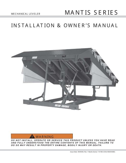
MECHANICAL LEVELER MANTIS SERIES<br />
INSTALLATION & OWNER’S MANUAL<br />
! WARNING<br />
DO NOT INSTALL, OPERATE OR SERVICE THIS PRODUCT UNLESS YOU HAVE READ<br />
AND FULLY UNDERSTOOD THE ENTIRE CONTENTS OF THIS MANUAL. FAILURE TO<br />
DO SO MAY RESULT IN PROPERTY DAMAGE, BODILY INJURY OR DEATH.<br />
Issue Date: 09/09/08, Rev.1 <strong>Mantis</strong> Series 110106-0 (Part #038-609E)
EXCLUSION OF LIABILITY<br />
The manufacturer assumes no liability for damage or injury to persons or property which have occurred as a result of defects or faults in the dock<br />
leveler delivered or due to incorrect use. The manufacturer also assumes no liability for lost profits, operating down times, or similar indirect losses<br />
which the buyer has incurred. Damage to third parties, irrespective of its nature, is not subject to compensation.<br />
The operating instructions are not subject to notification of amendment. The descriptions and illustrations included in our operating instructions and<br />
replacement parts list are not binding. In the interests of continuing product development, we reserve the right to make any changes at any time to the<br />
modules, components and accessories, concurrent with our continuing product improvement program, specifications are subject to change without<br />
notice. Please contact manufacturer for latest information.<br />
1<br />
1. Untrained personnel shall not be allowed to install,<br />
operate and/or service the mechanical dock<br />
leveler.<br />
2. Do not install this leveler, operate and/or service<br />
unless you have been trained and authorized to do<br />
so.<br />
3. Do not install, operate and/or service this leveler<br />
until you have read and understood all of the<br />
safety information and instructions contained<br />
herein and on the leveler.<br />
4. Do not operate this leveler until you have checked<br />
its condition. Report the need for leveler repairs to<br />
your supervisor immediately and do not operate<br />
leveler until repairs are made. Neglect may cause<br />
a minor repair to become a major service problem<br />
and cause the leveler to become unsafe.<br />
5. Do not work under or around a leveler being<br />
installed without first placing adequate barriers to<br />
positively prevent vehicle traffic from entering the<br />
work area.<br />
6. All electrical wiring, hook-up, repair and<br />
troubleshooting must be performed by a qualified<br />
service personnel. All wiring, hook-up and repairs<br />
must be made to meet all applicable codes. Before<br />
doing any electrical work, make certain the power<br />
is disconnected and properly tagged and / or<br />
locked out.<br />
7. Before performing any maintenance, secure<br />
maintenance strut in place.<br />
8. Do not load leveler beyond capacity shown on<br />
serial name plate on leveler.<br />
9. Stay clear of dock leveler and truck when truck is<br />
backing in or leaving dock area.<br />
10.Secure Truck by chocking truck wheels or use of<br />
vehicle restraint, as detailed by OSHA, before<br />
operating dock leveler.<br />
SAFETY PROCEDURES<br />
INTRODUCTION<br />
The following is intended to be a quick reference to some of the important procedures to follow while installing and using the <strong>Mantis</strong><br />
Series Model MTS-M <strong>Dock</strong> <strong>Leveler</strong>. It is not intended to cover, or suggest that it does cover, all procedures required to be followed<br />
to ensure safe installation & operation. Operators and installers should be aware of and abide by all workplace safety regulations that<br />
may apply to the operation and installation of the <strong>Mantis</strong> Series Model MTS-M <strong>Dock</strong> <strong>Leveler</strong>. These laws and regulations include but<br />
are not limited to:<br />
- Occupational Safety and Health Act (USA).<br />
- Occupational Safety and Health Acts for Individual States (USA).<br />
- Canadian Material Handling Regulations.<br />
For further information on these regulations and / or industry standards that may apply to this equipment, please contact:<br />
American National Standards Institute (ANSI)<br />
1430 Broadway<br />
New York, NY 10018<br />
(212) 642-4900<br />
! WARNING<br />
11. Do not use or move the dock leveler if anyone is<br />
under, in front and/or on dock leveler.<br />
12. Keep hands and feet clear of the dock leveler<br />
pinch points at all times. Never use hands to lift<br />
dock ramp and/or lip onto truck or to store dock<br />
leveler.<br />
13. Never try to lift or move any part of the <strong>Dock</strong><br />
<strong>Leveler</strong> without using the Release Chain.<br />
14. Do not drive on leveler unless lip is securely on<br />
truck bed and has a minimum of 4” (100mm)<br />
projection on truck bed.<br />
15. Do not exceed 4 mph when driving over dock<br />
leveler.<br />
16. Do not drive over edges of the leveler and / or dock<br />
bumper blocks (bumpers S/B bumper blocks are<br />
not structural).<br />
17. Do not leave equipment or material unattended on<br />
the leveler.<br />
18. Do not leave the leveler unattended in the<br />
deployed position.<br />
19. Do not use A fork truck or any other material<br />
handling equipment to lower leveler ramp.<br />
20. Never attempt to perform repairs. Always defer<br />
repairs to a qualified service technician.<br />
21. Do wear safety equipment as required.<br />
22. Do not mix drugs or alcohol with your job.<br />
This manual is intended to be readily available.<br />
Keep it near the leveler as a ready reference for<br />
anyone who may operate or service it. If the<br />
leveler being operated is not equipped with a<br />
manual, request to obtain one and have it located<br />
near the leveler.<br />
An authorized dealer or distributor is readily available to<br />
answer questions about leveler peration and maintenance<br />
and will provide additional information should it be<br />
required.<br />
Issue Date: 09/09/08, Rev.1 <strong>Mantis</strong> Series 110106-0 (Part #038-690E)
SAFETY WARNINGS<br />
Safety Signs and Safety Messages<br />
Improper operation can cause accidents. Don’t take chances with incorrect or damaged equipment. Read and<br />
understand the procedures for safe operation and maintenance outlined in this manual. Don’t hesitate to ask for help.<br />
Stay alert! Follow safety rules, regulations, and procedures. Avoid accidents by recognizing dangerous procedures or<br />
situations before they occur.<br />
Safety signs and messages are placed in this manual to provide instructions and identify specific areas where potential<br />
hazards exist and special precautions should be taken. Know and understand the meaning of these instructions, signs,<br />
and messages. Damage to the equipment, death, or serious injury to you or other persons may result if these<br />
messages are not followed. If warning decals are damaged, they must be replaced. Contact your Distributor for<br />
replacements.<br />
! DANGER ! WARNING<br />
This message indicates an imminently hazardous<br />
situation which, if not avoided, will result in death or<br />
serious injury<br />
! CAUTION<br />
This message indicates a potentially hazardous<br />
situation which, if not avoided, may result in minor<br />
or moderate injury.<br />
Operational Warning & Operating Instructions<br />
Permantly mount warning and operational instructions to be follow<br />
for use of loading dock equipment.<br />
Issue Date: 09/09/08, Rev.1 <strong>Mantis</strong> Series 110106-0 (Part #038-690E)<br />
This message indicates a potentially hazardous<br />
situation which, if not avoided, could result in death<br />
or serious injury.<br />
IMPORTANT<br />
This message is used when special precautions should<br />
be taken to ensure a correct action or to avoid damage<br />
to or malfunction of the <strong>Dock</strong> <strong>Leveler</strong> or a component.<br />
2
3<br />
TABLE OF CONTENTS<br />
OWNER’S PURCHASE RECORD<br />
Dealer: Date in Service:<br />
Owner: Number of Units:<br />
Order Number: Year of Construction:<br />
Serial Number(s):<br />
Safety<br />
Operational Use and Warning Signs<br />
Table of Contents<br />
Owner’s Record of Purchase<br />
Check Shipment Notice<br />
Installation Instructions<br />
Operating Instructions<br />
Maintenance<br />
<strong>Dock</strong> <strong>Leveler</strong> Components Diagram<br />
Trouble Shooting<br />
General Assembly Diagram & Parts<br />
- 25,000 lb, 30,000 lb, 35,000 lb 40,000 lb Capacity<br />
Holdown Assembly Diagram & Parts<br />
Reference Chart - <strong>Dock</strong> Size for Multi-Link Plate & Lip Spring Assist<br />
Lip Spring Assist Assembly<br />
Multi-Link Plate Assembly<br />
Brake Caliper Assembly<br />
<strong>Mechanical</strong> Fall Safe & Optional Below <strong>Dock</strong> Control Assembly<br />
Pivot (Lift) Arm Assembly<br />
Safety Decals<br />
Safety Skirts Assembly Diagram & Parts<br />
Notes<br />
Warranty<br />
CHECK SHIPMENT BEFORE INSTALLATION<br />
The leveler has been carefully checked at the manufacturer’s plant before shipment. In order to ensure that no damage<br />
has occurred during transport, the dock leveler should be checked upon receipt for transport damage and to ensure<br />
correct operation. Damage due to transport is to be listed on the signed copy on the freight document. The freight<br />
forwarder must be notified of any damage within 48 hours. Damaged dock levelers must not be put into use.<br />
The manufacturer offers a full line of dock levelers, dock safety equipment, accessories, ergonomic and scissor lift<br />
equipment, and industrial trucks. Concurrent with our continuing product improvement program, specifications are<br />
subject to change without notice. Please contact manufacturer for latest information. Some features illustrated may be<br />
optional in certain market areas.<br />
1-2<br />
2<br />
3<br />
3<br />
3<br />
4-6<br />
7-8<br />
9-10<br />
11<br />
12<br />
13-15<br />
16<br />
17<br />
18<br />
19<br />
20<br />
21<br />
22-23<br />
23<br />
24<br />
25<br />
26<br />
Issue Date: 09/09/08, Rev.1 <strong>Mantis</strong> Series 110106-0 (Part #038-690E)
! WARNING<br />
INSTALLATION INSTRUCTIONS<br />
Use caution when lifting or moving the leveler. Do not attempt to lift without suitable hoisting equipment capable of lifting<br />
as much as 3500 lbs.<br />
FORK LIFT TRUCK HANDLING SLING HANDLING<br />
SHIM 4" x 4"<br />
(102mm x 102mm)<br />
STITCH WELD<br />
1/4" 6”<br />
DOCK LEVELER<br />
BASE FRAME<br />
SHIM LIFT ARM<br />
BASE BRACKET<br />
5" X 5" - 127mm x 127 mm<br />
SHIM BOTH SIDES<br />
5" X 5" - 127mm x 127 mm<br />
Figure 1 : <strong>Dock</strong> <strong>Leveler</strong> Installation Pictorial<br />
SHIM BOTH SIDES<br />
5" X 5" - 127mm x 127 mm<br />
Issue Date: 09/09/08, Rev.1 <strong>Mantis</strong> Series 110106-0 (Part #038-690E) 4
5<br />
! WARNING<br />
Do not install, operate and/or service this leveler until you<br />
have read and understood all of the safety information<br />
and instructions contained herein and on the leveler.<br />
Do not work under or around leveler being installed<br />
without first placing adequate barriers to positively<br />
prevent vehicle traffic from entering the work area.<br />
Keep hands and feet clear of dock leveler pinch points<br />
IMPORTANT<br />
The following information is essential for proper<br />
installation<br />
Pit Curb Angles<br />
A. Must be level side-to-side and front-to-back.<br />
B. Must be square at both rear corners.<br />
C. Side curb angles must be parallel to each other.<br />
D. Finished floor to be flush with top surface of curb angle.<br />
The leveler must be welded to a firmly embedded steel<br />
or other dock steel as described in the installation<br />
instructions.<br />
Do not attempt to use only bolts or anchors, to attach<br />
the dock leveler to the concrete.<br />
1. Prior to installation, clean pit thoroughly and verify that all<br />
dimensions are in accordance with manufacturer’s<br />
specifications.<br />
2. Measure height of rear corners of dock leveler, bottom of frame<br />
to top of deck plate, typically 19” or 23”(485 or 585mm).<br />
Measure depth of pit at both rear corners where rear bottom<br />
corners of frame will be positioned. Locate and place suitable<br />
shims (not supplied) in pit corners to produce a depth to match<br />
frame height. See Figure 2, Page 3.<br />
3. Measure height of front corners of dock leveler, bottom of frame<br />
to top of deck plate, typically 19-1/2” or 23-1/2” (495 or<br />
595mm). Measure depth of pit at both front corners where front<br />
bottom corners of frame will be positioned. Locate and place<br />
suitable shims (not supplied) at both front corners to produce a<br />
depth to match frame height. See Figure 2, Page 3.<br />
! WARNING<br />
Use caution when lifting or moving the leveler. Do not<br />
attempt to lift without suitable hoisting equipment capable<br />
of lifting as much as 3500 lbs.<br />
Do not work beneath a raised object. Follow all hoisting<br />
safety requirements.<br />
4. Using extreme caution, sling dock leveler into place squarely<br />
above pit and lower gently onto pre-located shims. Locate and<br />
square dock leveler to best suit pit and dock face. Space<br />
between sides of deck and sides of pit should be equal. See<br />
Figure 2 Page 5.<br />
! WARNING<br />
Use caution when unbanding the leveler. Keep hands clear<br />
of pinch points and wear appropriate safety attire. -<br />
glasses, gloves and work boots.<br />
Note: There is the potential for the dock leveler to deploy<br />
when the shipping bolt is removed. The holdown<br />
mechanism must be engaged prior to removal of shipping<br />
bolt.<br />
INSTALLATION INSTRUCTIONS<br />
Typically 19” or<br />
23”(485 or 585mm)<br />
C<br />
PIT MUST BE<br />
KEPT SQUARE<br />
D<br />
DOCK BUMPERS<br />
Typically 19-1/2” or<br />
23-1/2” (495 or 595mm).<br />
Figure 2 : Pit Layout - Typical<br />
5. Remove sling brackets, chains, etc. from the deck. Remove<br />
and discard the shipping bolt from the front of the dock<br />
leveler lip plate.<br />
! WARNING<br />
Do not work beneath dock leveler without engaging<br />
maintenance strut.<br />
6. If rear beam does not line up squarely with rear curb angle,<br />
use 3” x 6” (75mm x 150mm) shims of suitable thickness to<br />
fully support top rear and bottom rear of rear beam at weld<br />
areas. Weld rear beam to curb steel with 1/4” x 6” (6mm x<br />
150mm) welds, on 9-5/8” (250mm) centers. See Figure 1,<br />
Page 2.<br />
IMPORTANT<br />
It is important that these shims fill space between<br />
bottom edge of back beam and face of curb angle as<br />
well as top edge, behind each hinge lug. Assure the top<br />
of the back beam is flush with the top surface of rear<br />
curb angle and finish weld back beam to curb angle as<br />
detailed in Figure 1, Page 2.<br />
7. Partially operate the <strong>Dock</strong> <strong>Leveler</strong> by pulling firmly upward on<br />
the hold down release ring (located in the right rear corner of<br />
the deck surface) and quickly releasing it so that the deck<br />
rises approximately 4” – 6”.<br />
Issue Date: 09/09/08, Rev.1 <strong>Mantis</strong> Series 110106-0 (Part #038-690E)
8. Lower the deck back to its stored position by walking up the<br />
slope of the deck. Ensure the deck is fully down to stowed<br />
position with the tip of lip plate located inside the lip<br />
keepers.<br />
9. Check that all four corners of the dock are square and flush<br />
to the floor level. Make note of areas where shims need to<br />
be added or removed.<br />
10. Adjust the height of all front shims as required to level the<br />
front sides of the deck with the pit side curb angles.<br />
11. Tack-weld the front shims together.<br />
12. Tack-weld the welded front shims to the front of the <strong>Dock</strong><br />
<strong>Leveler</strong> frame.<br />
13. Tack-weld the welded front shims to the front pit curb angle.<br />
14. Repeat this process for the rear frame parts and shims. To<br />
do this, the deck must be raised again and a maintenance<br />
strut put in place.<br />
MAINTENANCE<br />
STRUT<br />
! WARNING<br />
Do not work beneath dock leveler without engaging<br />
maintenance strut.<br />
15. Firmly pull up on the hold down release chain and hold it to<br />
raise the deck to full height and extend the lip plate.<br />
16. Quickly place the maintenance strut in its vertical position<br />
before the lip plate folds in to its pendant position.<br />
17. Remove pin from telescopic maintenance strut, extend the<br />
maintenance strut to the desired height, reinsert pin and<br />
walk the deck down to engage the maintenance strut.<br />
18. Tack-weld the rear shims together.<br />
19. Tack-weld the welded rear shims to the rear <strong>Dock</strong> <strong>Leveler</strong><br />
frame Finish weld all shims, Refer to Figure 1 : <strong>Dock</strong><br />
<strong>Leveler</strong> Installation Pictorial.<br />
20. Finish weld all rear shims together.<br />
21. Finish weld all rear shims to rear <strong>Dock</strong> <strong>Leveler</strong> frame.<br />
22. Finish weld all front frame shims together.<br />
23. Finish weld front frame shims securely to the front frame.<br />
24. Finish weld front frame shims securely to the front pit curb<br />
angle.<br />
INSTALLATION INSTRUCTIONS<br />
UPPER REAR<br />
PIT ANGLE<br />
REAR FRAME<br />
ANGLE<br />
25. Finish weld the upper dock leveler rear frame to the upper<br />
rear pit curb angle. Stitch weld centered on and opposite to<br />
rear frame hinge spools.<br />
26. Install specified dock bumpers as required.<br />
REMOVE SHIPPING BOLT<br />
27. Remove the shipping lock bolt and nut from front end of<br />
sliding side safety skirts (if equipped) and allow front ends to<br />
swing down to working position.<br />
28. Mount “Operating Hazards DANGER” placard, provided with<br />
these Instructions to the wall in plain view of dock leveler<br />
operations.<br />
29. Mount No. 2 envelope containing Owner / Operator Manual<br />
and Warranty Validation Form to be returned to the<br />
manufacturer.<br />
30. Perform a final inspection and determine that all work is<br />
completed satisfactorily. Clean pit and work area thoroughly<br />
and apply touch-up paint to weld burn areas, scratches, etc.<br />
31. Test operate the unit through several full cycles of all<br />
functions.<br />
Refer to Owner’s Manual for Operating Procedures.<br />
If adjustments are required, refer to Troubleshooting<br />
Installation Inspection<br />
1. Clean up the entire work area and apply touch-up paint to all<br />
welds, scratches and burns.<br />
2. Ensure all concrete wedge anchors have been securely<br />
tightened.<br />
! WARNING<br />
Read and understand this entire manual prior to<br />
operating.<br />
3. Test operate the unit through several full cycles of operation.<br />
Refer to: Operating Procedures. If problems are noted, See<br />
Section on Troubleshooting.<br />
4. Mount Warning & Operational Instructions - See Page 2.<br />
5. Leave these Instructions with the <strong>Dock</strong> <strong>Leveler</strong> for use by<br />
owner.<br />
Issue Date: 09/09/08, Rev.1 <strong>Mantis</strong> Series 110106-0 (Part #038-690E) 6
FUNCTIONAL DESCRIPTION<br />
7<br />
! WARNING<br />
Do not install this leveler, operate and/or service unless<br />
you have been trained and authorized to do so.<br />
Do not install, operate and/or service this leveler until<br />
you have read and understood all of the safety<br />
information and instructions contained herein and on<br />
the leveler.<br />
Do not operate the dock leveler beyond its rated<br />
capacity.<br />
Do not operate this leveler until you have checked its<br />
condition. Report the need for leveler repairs to your<br />
supervisor immediately and do not operate leveler until<br />
repairs are made. Neglect may cause a minor repair to<br />
become a major service problem and cause the leveler to<br />
become unsafe.<br />
Never try to lift or move any part of the <strong>Dock</strong> <strong>Leveler</strong><br />
without using the Release Chain Ring.<br />
Keep hands and feet clear of dock leveler pinch points at<br />
all times. Never use hands to lift dock ramp and/or lip<br />
onto truck or to store dock leveler.<br />
Do not drive on leveler unless lip is securely on truck<br />
bed and has a minimum of 4” (100mm) projection on<br />
truck bed.<br />
Do not exceed 4 mph when driving over dock leveler.<br />
Do not drive over edges of the leveler and / or dock<br />
bumper blocks (bumpers blocks are not structural).<br />
The <strong>Dock</strong> <strong>Leveler</strong> is intended to be used as a bridge located<br />
between a loading dock floor surface and the truck bed.<br />
The <strong>Dock</strong> <strong>Leveler</strong> upper deck plate complete with a hinged,<br />
vertically hanging lip plate is located flush with the floor surface<br />
and the edge of the dock, in a shallow pit.<br />
The trailer and the truck are parked and blocked in place against<br />
the outer wall of the loading dock, in working alignment with the<br />
<strong>Dock</strong> <strong>Leveler</strong>. A <strong>Dock</strong> <strong>Leveler</strong> in combination with a Vehicle<br />
Restraint are ideal for this application. Consult your local<br />
Dealer/Distributor.<br />
The <strong>Dock</strong> <strong>Leveler</strong> is operated allowing tensioned springs to raise<br />
the front of the Deck. The hinged lip plate raises with the deck<br />
and it’s leading edge swings out horizontally over the rear of the<br />
truck bed, as the deck reaches its fully raised position.<br />
The <strong>Dock</strong> <strong>Leveler</strong> operator walks up the sloped deck and his/ her<br />
body weight causes the deck and the extended lip to lower<br />
together until the underside of the extended lip makes contact<br />
on the bed of the truck.<br />
A bridge is now formed that is supported at the building end by<br />
the dock floor and at the vehicle end by the truck’s bed.<br />
No other means of support is provided when in this position.<br />
During loading / unloading operations, the deck and lip automatically<br />
follow the raising and lowering movement of the truck.<br />
The <strong>Dock</strong> <strong>Leveler</strong> is returned to its original stored position by the<br />
<strong>Dock</strong> <strong>Leveler</strong> operator. In the stored position, both ends of the<br />
<strong>Dock</strong> <strong>Leveler</strong> upper deck plate are supported. The building<br />
end is supported by the dock floor and the vehicle end is<br />
supported by the lip, lip keepers, and the pit floor.<br />
OPERATING INSTRUCTIONS<br />
Operating Procedure<br />
! WARNING<br />
Secure the truck with a vehicle restraint, wheel<br />
chocks or other method before commencing traffic<br />
across the dock leveler.<br />
1. In the stored position, the lift springs are stretched and the<br />
lifting arm is at the base of the cam.<br />
IMPORTANT<br />
Releasing the hold down release ring will stop the<br />
upward travel of the dock.<br />
2. To raise the dock leveler, the Hold Down release ring is<br />
pulled firmly up and held. As the deck rises, the lip plate<br />
will extend.<br />
3. Once the deck is in the raised position, the operator walks<br />
the deck down to the loading / unloading position.<br />
4. The loading/unloading operation is performed and<br />
completed.<br />
Issue Date: 09/09/08, Rev.1 <strong>Mantis</strong> Series 110106-0 (Part #038-690E)
5. To return the deck to the stored position, the Hold Down<br />
release ring is pulled and held just long enough for the lip<br />
plate to clear the trucks loading bed. After the lip plate has<br />
dropped to the pendant position, the operator can then<br />
began to walk down the deck.<br />
6. The operator walks down the deck until it reaches the<br />
stored position, ensuring that the lip is located inside the lip<br />
keepers<br />
! WARNING<br />
The truck should never be allowed to depart<br />
with the lip plate resting on the loadbed.<br />
7. The operator releases the vehicle restraint or removes the<br />
wheel chocks to allow the truck to depart. The operator then<br />
indicates to the truck driver that it is safe to depart. A<br />
manual communication light system or in combination with<br />
a vehicle restraint is ideal for this application; consult your<br />
local Dealer/Distributor.<br />
Below <strong>Dock</strong> Level Control: End Loading<br />
Refer also to <strong>Mechanical</strong> Fall Safe and Below Level Control<br />
Operation.<br />
This section describes operation of a dock leveler in situations<br />
where contact of the dock leveler lip plate with the vehicle load<br />
bed is not possible (e.g. loading/unloading the first skid or<br />
pallet from the vehicle load bed where there is insufficient<br />
surface area to extend the dock leveler lip plate.)<br />
The <strong>Dock</strong> <strong>Leveler</strong> deck is raised by firmly pulling up the Hold<br />
Down release ring in the right rear corner of the deck and<br />
holding until the deck rises to full height. The operator then<br />
releases the Hold Down release ring and walks down the deck.<br />
The deck is lowered by the operators weight as he walks up its<br />
slope. The operator must properly time the walk down such<br />
that the dock leveler lip plate folds in enough to miss the<br />
vehicle load bed, but not enough for it to engage the lip<br />
keepers.<br />
OPERATING INSTRUCTIONS<br />
The lip plate is allowed to remain in the pendant position and is<br />
allowed to slip in between the rear of the transporter vehicle<br />
load bed and the building foundation without engaging the lip<br />
keepers. When unloading a truck and the first skid or pallet has<br />
been removed, the dock leveler must be reset with the lip plate<br />
in the extended position. When the lip makes firm contact with<br />
the vehicle load bed, the unit is ready for traffic.<br />
<strong>Mechanical</strong> Fall Safe and<br />
Below Level Control Operation<br />
The <strong>Mechanical</strong> Fall Safe Option consists of two Support Legs<br />
that are held rigidly in a vertical position by springs to arrest<br />
downward travel of the deck by approximately 2-1/2” (60mm)<br />
below level position.<br />
In situations where the deck needs to be operated below<br />
crosstraffic position by more than 2-1/2”, the Fall Safe Support<br />
Legs need to be retracted by using the Control Activator<br />
located at the left front corner of the deck. The Control<br />
Activator pull ring retracts the Support Legs to allow the dock<br />
leveler to travel a full 12” below level position. The Support<br />
Legs will return to the normal pendant position when the<br />
Control Activator ring is released and the deck is raised high<br />
enough by operation of<br />
the Hold Down release ring.<br />
The loading/unloading operation is performed and completed.<br />
Follow Steps 5 and 6 of Operational Procedures to store dock.<br />
If further loading/unloading required follow Safety and<br />
Operational Procedures to resume normal operation.<br />
Issue Date: 09/09/08, Rev.1 <strong>Mantis</strong> Series 110106-0 (Part #038-690E) 8
Planned Maintenance<br />
In addition to the daily operator inspection, the<br />
manufacturer recommends and local Government<br />
regulations may require that a planned maintenance<br />
(PM) and safety inspection program be performed by a<br />
trained and authorized service technician on a regular<br />
basis to maintain the equipment in safe operating<br />
condition. The PM will provide an opportunity to make a<br />
thorough inspection of the safety and operating<br />
condition of the <strong>Dock</strong> <strong>Leveler</strong>. Necessary adjustments<br />
and repairs can be done during the PM, which will<br />
increase the life of components and reduce<br />
unscheduled downtime and increase safety. The PM<br />
can be scheduled to meet any particular application and<br />
<strong>Dock</strong> <strong>Leveler</strong> usage.<br />
The procedures for a periodic planned maintenance<br />
program that covers inspections, operational checks,<br />
cleaning, lubrication, and minor adjustments are<br />
outlined in this manual. An authorized dealer or<br />
distributor is prepared to assist with a Planned<br />
Maintenance Program by trained service personnel<br />
who possess expertise in <strong>Dock</strong> <strong>Leveler</strong> safety and<br />
efficiency.<br />
9<br />
IMPORTANT<br />
Improper adjustments and/or lubrication may cause<br />
operational equipment problems.<br />
INSPECT<br />
CLEAN<br />
MAINTENANCE<br />
Operator Daily Inspection<br />
The <strong>Dock</strong> <strong>Leveler</strong> should always be examined by the<br />
operator to ensure it is safe to operate, PRIOR TO ANY<br />
USE. The importance of this procedure is emphasized in<br />
this manual with a brief illustrated review and later with<br />
more detailed instructions. The manufacturer<br />
recommends making multiple photocopies of Operator’s<br />
Daily Checklist. The operator should make a daily<br />
inspection prior to use; filling out this form in order to<br />
keep a daily record of operation and maintenance<br />
issues.<br />
Routine Servicing And Maintenance<br />
Regular maintenance and care of the <strong>Dock</strong> <strong>Leveler</strong> is<br />
very important for cost and operation efficiency and<br />
more importantly; operator safety. A faulty <strong>Dock</strong> <strong>Leveler</strong><br />
is a potential source of danger to the operator, and to<br />
other personnel working near it. As with all quality<br />
equipment, keep the <strong>Dock</strong> <strong>Leveler</strong> in good operating<br />
condition by following the recommended schedule of<br />
maintenance.<br />
Failure to properly maintain or operate the dock leveler<br />
within its rated capacity can void the manufacturer<br />
warranty.<br />
Complete the Warranty Validation Form provided with<br />
this manual and return it to factory.<br />
EXTENSION DECK SAFETY LIP HINGE LIP EXTENSION HOLDOWN<br />
SPRINGS ASSEMBLY LEGS ASSEMBLY SYSTEM ASSEMBLY<br />
ALL THE ABOVE EVERY 90 DAYS<br />
ALL THE ABOVE EVERY 90 DAYS<br />
(Lip Clean As Required)<br />
LUBRICATE As Needed Every 90 Days Every 90 Every 90 Every 90 Days Not Required<br />
Pivot Points Days Days (Light Oil)<br />
(Light Oil) (Light Oil) (Grease)<br />
ADJUST As Needed Not Required Not Required Not Required As Needed As Needed<br />
Issue Date: 09/09/08, Rev.1 <strong>Mantis</strong> Series 110106-0 (Part #038-690E)
Customer Tel<br />
SWO#<br />
Location Cust. Contact<br />
Date Inspected By<br />
CLEAN Repairs? O K CHECK / ADJUS T / LUBE Repairs? O K<br />
Pit Area Multilink Plate<br />
Deck Hinge Push Rod<br />
Lip Hinge Push Rod Pivots<br />
Fasteners<br />
C H ECK Repairs? O K Holdown Strap Retainer<br />
Tension Spring (Multilink Plate)<br />
Hold Down Strap<br />
Tension Strap Fall Safe Chain<br />
Cam Roller Fall Safe Spring<br />
Tension Spring (strap)<br />
Lip Chain Lift Spring Tension<br />
Lip Springs<br />
Structural Damage<br />
Full Operating Cycle Lip Hinge<br />
<strong>Dock</strong> Bumpers / Extensions Shock Absorber Pivot<br />
Overhead Door Lip Actuating Pivots<br />
Curb Angle Lifting Arm Pivots<br />
Installation / Structural Welds Lip Release Cam<br />
Safety Skirts<br />
Lifting Arm Bushings<br />
Hold Down<br />
Cotter Pin Wear<br />
C O MMENT S<br />
R E PAIRS R ECO MMENDED<br />
! WARNING<br />
Do not install this leveler, operate and/or service<br />
unless you have been trained and authorized to do so.<br />
PM CHECK LIST - DOCK EQUIPMENT<br />
Issue Date: 09/09/08, Rev.1 <strong>Mantis</strong> Series 110106-0 (Part #038-690E) 10
11<br />
HOLD<br />
DOWN<br />
MECH<br />
BRAKE<br />
DISC<br />
HOLD<br />
DOWN<br />
STRAP<br />
BRAKE<br />
HANDLE<br />
LIP ASSIST SPRING<br />
(FOR LARGER SIZE DOCKS ONLY)<br />
TENSION<br />
STRAP<br />
TENSION<br />
SPRING<br />
LIP<br />
KEEPERS<br />
MECHANICAL DOCK LEVELER COMPONENTS<br />
MAINTENANCE<br />
STRUT<br />
STRAP<br />
RETAINER<br />
LIP SPRING<br />
LIP<br />
STOP<br />
BASE FRAME<br />
LIP<br />
ARM<br />
PIVOT<br />
PIN<br />
LIP PIN<br />
PUSH ROD<br />
DECK<br />
WELDMENT<br />
DECK PIN<br />
MULTI LINKS<br />
PLATE<br />
LIP CHAIN AND<br />
CHAIN TENSION<br />
SPRING<br />
MAIN<br />
LIFT<br />
SPRING<br />
LIFT SPRING<br />
BRACKET<br />
LIFT ARM<br />
Issue Date: 09/09/08, Rev.1 <strong>Mantis</strong> Series 110106-0 (Part #038-690E)
TROUBLE SHOOTING<br />
Problem Problem Cause<br />
Deck does not raise<br />
Deck does not raise fast<br />
quickly or smoothly<br />
Lip plate does reach the<br />
fully extended position<br />
Deck will not ‘Walk’ down<br />
Deck is very hard to ‘Walk’<br />
down<br />
Lip does not release and swing<br />
down when truck departs<br />
Deck does not stay down.<br />
Springs back up after walking<br />
down<br />
Lip strikes rear of truck as the deck raises,<br />
deck stops or slows down, and lip does not<br />
reach the extended position<br />
Lip will not clear rear of vehicle when<br />
attempting to return dock leveler to stored<br />
position with truck parked at dock<br />
<strong>Dock</strong> bumper damage that is abnormal and<br />
excessive<br />
• Hold down mechanism not releasing.<br />
• Release chain, brake handle jammed or tension spring broken.<br />
• Foreign material lodged between side of deck and pit wall.<br />
• Damaged or missing bumpers allowing truck to contact and hold lip.<br />
• Lifting arm cam roller knocked off cam and jammed.<br />
• Foreign material lodged in lip hinge, preventing full rotation.<br />
• Deck drag on side of pit, slowing deck.<br />
- Foreign material lodged between side of deck and pit wall.<br />
- Safety skirt damaged and dragging on pit wall (when used).<br />
- Out of square pit causing deck to drag on side of pit.<br />
• Lack of lubrication on lip hinge spools.<br />
• Chain attached to lip spring broken or lip spring broken.<br />
• Lifting springs require adjustment.<br />
- Assure all other possible causes have been eliminated before changing spring adjustment.<br />
• Chain attached to lip spring broken or jammed.<br />
• Lip Assist Spring jammed or broken.<br />
• Lip linkage bent or broken.<br />
• Foreign material lodged in lip linkage.<br />
Deck drags on side wall of pit • Pit/dock is out of square<br />
Issue Date: 09/09/08, Rev.1 <strong>Mantis</strong> Series 110106-0 (Part #038-690E)<br />
• Foreign material in pit, blocking mechanism.<br />
• Side safety skirts badly damaged and jammed against pit wall (when used).<br />
• Lifting arm cam roller knocked off cam, causing lifting arm to jam against cam.<br />
• Weather seals, skirts or deck dragging on pit wall.<br />
• Foreign material in pit.<br />
• Cam roller grooved badly by cam wear.<br />
• Cam roller bearing seized.<br />
• Lack of lubrication.<br />
• Lift springs adjusted improperly.<br />
- Tension has been mistakenly increased to overcome another problem.<br />
• Lip Assist Spring jammed, damaged by foreign material in pit.<br />
• Gas spring jammed.<br />
• Multilink plate bent, jammed, or damaged by foreign material in pit.<br />
• Hold down strap broken.<br />
• Hold down assembly jammed.<br />
- Foreign material in hold down assembly stopping rotation of ratchet hub.<br />
- Pawl worn or pawl spring broken.<br />
- Tension strap broken or strap tension spring broken.<br />
• Brake handle jammed, foreign material lodged under brake handle.<br />
• Brake does not engage properly.<br />
- Brake disc worn or damaged.<br />
- Brake lining worn.<br />
- Accidentally lubricated brake disc during routine maintenance.<br />
• Brake caliper damage or jammed.<br />
- Caliper holder damaged by foreign material.<br />
- Improperly adjusted Brake lining clearance.<br />
- Jam nut of adjuster pin not secured properly.<br />
• Damaged or missing dock bumpers allow the vehicle to be parked too close to the<br />
dock leveler.<br />
• Height differential between dock and transporter vehicle bed is greater than recommended.<br />
• Lip linkage damaged or gas spring broken.<br />
• Damaged or missing dock bumpers allow truck to be parked too close to the dock leveler.<br />
• Height differential between dock and transporter vehicle bed is greater than recommended.<br />
• Lip linkage damaged or jammed causing lip to be held out too late in cycle.<br />
• Lip Assist Spring jammed.<br />
• Shunting tractors with raise able fifth wheel damage bumpers by causing excess vertical<br />
movement of rear of trailer.<br />
• Air-ride suspension trailers can cause severe bumper damage if the trailer is raised against<br />
the bottom of or lowered on top of the bumper.<br />
12
35<br />
16<br />
13<br />
24<br />
25<br />
45<br />
49<br />
47<br />
50<br />
29<br />
41<br />
30<br />
36<br />
37<br />
38<br />
26<br />
19<br />
39<br />
GENERAL ASSEMBLY - 25, 30, 35 & 40,000 LB. CAPACITY<br />
42<br />
43<br />
34<br />
44<br />
13<br />
9<br />
2<br />
15<br />
17<br />
29<br />
28<br />
30<br />
20<br />
21<br />
1<br />
32<br />
31<br />
40<br />
23<br />
4<br />
3<br />
15<br />
21<br />
5<br />
9<br />
20<br />
16<br />
11<br />
14<br />
33<br />
48<br />
10 6<br />
8<br />
7<br />
Issue Date: 09/09/08, Rev.1 <strong>Mantis</strong> Series 110106-0 (Part #038-690E)<br />
8<br />
20<br />
12<br />
21<br />
17<br />
46<br />
27<br />
22
GENERAL ASSEMBLY - 25, 30, 35 & 40,000 LB. CAPACITY<br />
ITEM QTY PART NUMBER GENERAL DESCRIPTION SPECIFIC DESCRIPTION<br />
1 1 ------------------- Base Frame Weldment MTS-M6’-6’ MTS - M <strong>Dock</strong><br />
2 1 ------------------- Deck Weldment MTS - M <strong>Dock</strong><br />
3 1 200-03269 Lip Weldment (1/2” x 16” x 72”) MTS - M <strong>Dock</strong> (25 & 30K)<br />
3 1 200-03270 Lip Weldment (1/2” x 16” x 78”) MTS - M <strong>Dock</strong> (25 & 30K)<br />
3 1 200-03271 Lip Weldment (1/2” x 16” x 83”) MTS - M <strong>Dock</strong> (25 & 30K)<br />
3 1 200-03272 Lip Weldment (1/2” x 18” x 72”) MTS - M <strong>Dock</strong> (25 & 30K)<br />
3 1 200-03273 Lip Weldment (1/2” x 18” x 78”) MTS - M <strong>Dock</strong> (25 & 30K)<br />
3 1 200-03274 Lip Weldment (1/2” x 18” x 83”) MTS - M <strong>Dock</strong> (25 & 30K)<br />
3 1 200-03275 Lip Weldment (1/2” x 20” x 72”) MTS - M <strong>Dock</strong> (25 & 30K)<br />
3 1 200-03276 Lip Weldment (1/2” x 20” x 78”) MTS - M <strong>Dock</strong> (25 & 30K)<br />
3 1 200-03277 Lip Weldment (1/2” x 20” x 83”) MTS - M <strong>Dock</strong> (25 & 30K)<br />
3 1 200-03278 Lip Weldment (5/8” x 16” x 72”) MTS - M <strong>Dock</strong> (35K)<br />
3 1 200-03279 Lip Weldment (5/8” x 16” x 78”) MTS - M <strong>Dock</strong> (35K)<br />
3 1 200-03280 Lip Weldment (5/8” x 16” x 83”) MTS - M <strong>Dock</strong> (35K)<br />
3 1 200-03281 Lip Weldment (5/8” x 18” x 72”) MTS - M <strong>Dock</strong> (35K)<br />
3 1 200-03282 Lip Weldment (5/8” x 18” x 78”) MTS - M <strong>Dock</strong> (35K)<br />
3 1 200-03283 Lip Weldment (5/8” x 18” x 83”) MTS - M <strong>Dock</strong> (35K)<br />
3 1 200-03284 Lip Weldment (5/8” x 20” x 72”) MTS - M <strong>Dock</strong> (35K)<br />
3 1 200-03285 Lip Weldment (5/8” x 20” x 78”) MTS - M <strong>Dock</strong> (35K)<br />
3 1 200-03286 Lip Weldment (5/8” x 20” x 83”) MTS - M <strong>Dock</strong> (35K)<br />
3 1 200-03441 Lip Weldment (5/8” x 16” x 72”) MTS - M <strong>Dock</strong> (40K)<br />
3 1 200-03442 Lip Weldment (5/8” x 16” x 78”) MTS - M <strong>Dock</strong> (40K)<br />
3 1 200-03443 Lip Weldment (5/8” x 16” x 83”) MTS - M <strong>Dock</strong> (40K)<br />
3 1 200-03441-1 Lip Weldment (5/8” x 18” x 72”) MTS - M <strong>Dock</strong> (40K)<br />
3 1 200-03442-1 Lip Weldment (5/8” x 18” x 78”) MTS - M <strong>Dock</strong> (40K)<br />
3 1 200-03443-1 Lip Weldment (5/8” x 18” x 83”) MTS - M <strong>Dock</strong> (40K)<br />
3 1 200-03441-2 Lip Weldment (5/8” x 20” x 72”) MTS - M <strong>Dock</strong> (40K)<br />
3 1 200-03442-2 Lip Weldment (5/8” x 20” x 78”) MTS - M <strong>Dock</strong> (40K)<br />
3 1 200-03443-2 Lip Weldment (5/8” x 20” x 83”) MTS - M <strong>Dock</strong> (40K)<br />
4 1 200-02354 Deck Pin (6’ W) MTS All Capacity<br />
4 1 200-02493 Deck Pin (6’6” W) MTS All Capacity<br />
4 1 200-02492 Deck Pin (7’ W) MTS All Capacity<br />
5 1 200-02353 Lip Pin (6’ W) MTS (25 & 30K)<br />
5 1 200-02468 Lip Pin (6’6” W) MTS (25 & 30K)<br />
5 1 200-02469 Lip Pin (7’ W) MTS (25 & 30K)<br />
5 1 200-02577 Lip Pin (6’ W) MTS (35K)<br />
5 1 200-02578 Lip Pin (6’6” W) MTS (35K)<br />
5 1 200-02579 Lip Pin (7’ W) MTS (35K)<br />
5 1 109-699 Lip Pin (6’ W) MTS (40K)<br />
5 1 109-687-1 Lip Pin (6’6” W) MTS (40K)<br />
5 1 109-690 Lip Pin (7’ W) MTS (40K)<br />
6 1 200-02385 Pivot Arm Assy MTS-M DOCK (25-35K)<br />
6 1 200-02385-1 Pivot Arm Assy MTS-M DOCK (25-35K)<br />
6 1 200-03471 Pivot Arm Assy MTS-M DOCK (40K)<br />
7 1 200-02389 Pivot Pin MTS All Model<br />
8 4 013-011 Spring Pin MTS All Model<br />
9 2 013-090 Spring Pin MTS All Model<br />
10 1 200-02371 Spacer Tube MTS All Model<br />
11 1 200-03392-1 Multilink Plate Weldment MTS All Model<br />
Issue Date: 09/09/08, Rev.1 <strong>Mantis</strong> Series 110106-0 (Part #038-690E) 14
15<br />
GENERAL ASSEMBLY - 25, 30, 35 & 40,000 LB. CAPACITY<br />
ITEM QTY PART NUMBER GENERAL DESCRIPTION SPECIFIC DESCRIPTION<br />
12 1 200-03412 Push Rod Weldment MTS All Model<br />
13 1 012-237 Flat Washer MTS All Model<br />
14 1 010-044 Hex Head Cap Screw MTS All Model<br />
15 5 012-212 Flat Washer MTS All Model<br />
16 3 010-027 Hex Head Cap Screw MTS All Model<br />
17 3 011-554 Nylon Insert Lock Nut MTS All Model<br />
18 1 010-099 Hex Head Cap Screw MTS All Model<br />
19 1 ----------- Lip Assist Spring Refer to Chart on Page 16 if required<br />
20 2 013-598 Pin MTS All Model<br />
21 2 013-020 Cotter Pin MTS All Model<br />
22 1 200-02360 Main Spring Bracket (8’ L <strong>Dock</strong>) MTS - M (6’ & 6’6” W)<br />
22 1 200-02979 Main Spring Bracket (8’ L <strong>Dock</strong>) MTS - M (7’ W)<br />
22 1 200-02972 Main Spring Bracket (6’ L <strong>Dock</strong>) MTS - M (6’, 6’6” & 7’ W)<br />
22 1 200-03468 Main Spring Bracket (10’ L <strong>Dock</strong>) MTS DOCK<br />
23 1 011-531 Hex Nut MTS All Model<br />
24 1 200-03018 Hold Down Box MTS All Model<br />
25 4 012-201 Lock Washer MTS All Model<br />
26 1 200-023459 Brake Handle MTS - M (8’ L <strong>Dock</strong>)<br />
26 1 200-02546 Brake Handle MTS - M (6’ L <strong>Dock</strong>)<br />
26 1 200-03465 Brake Handle MTS - M (10’ L <strong>Dock</strong>)<br />
27 2 200-02414C Tension Spring (Deck) MTS - M (6’ L <strong>Dock</strong>)<br />
27 2 200-02414C Tension Spring (Deck) MTS - M (8’ L <strong>Dock</strong>)<br />
27 3 200-02414C Tension Spring (Deck) MTS - M (8’ L <strong>Dock</strong>, 7’ W)<br />
27 4 200-02414C Tension Spring (Deck) MTS - M (10’ L <strong>Dock</strong>)<br />
28 1 200-02346 Strap Retaining Bar MTS All Model<br />
29 4 010-001 Hex Head Cap Screw MTS All Model<br />
30 4 011-506 Hex Nut MTS All Model<br />
31 1 010-060 Hex Head Cap Screw MTS All Model<br />
32 1 200-02411 Tension Spring (Lip) MTS All Model<br />
33 1 200-02582 Chain Assy MTS All Model<br />
34 1 788-197 Pull Chain MTS All Model<br />
35 1 200-5001 Safety Strut Assy MTS All Model<br />
36 1 200-02422 Hold Down Strap MTS All Model<br />
37 1 200-02423 Tension Strap MTS All Model<br />
38 1 200-02409 Strap Retaining Pin MTS All Model<br />
39 1 200-02413 Tension Spring MTS - M (8’ & 10’ L <strong>Dock</strong>)<br />
39 1 200-02547 Tension Spring MTS - M (6’ L <strong>Dock</strong>)<br />
40 1 012-255 Spacer Washer MTS All Model<br />
41 2 012-202 Spring Washer MTS All Model<br />
42 1 010-039 Hex Head Cap Screw MTS All Model<br />
43 2 012-211 Flat Washer MTS All Model<br />
44 1 011-552 Nylon Insert Lock Nut MTS All Model<br />
45 5 011-507 Hex Nut MTS All Model<br />
46 1 011-508 Hex Nut MTS All Model<br />
47 2 011-104 Button Head Cap Screw MTS All Model<br />
48 1 200-02412 Tension Spring (for chain assy, item #33) MTS All Model<br />
49 1 011-183 Button Head Cap Screw MTS All Model<br />
50 1 012-208 Flat Washer MTS All Model<br />
Issue Date: 09/09/08, Rev.1 <strong>Mantis</strong> Series 110106-0 (Part #038-690E)
HOLDOWN GENERAL ASSEMBLY<br />
HOLDOWN GENERAL ASSEMBLY<br />
ITEM QTY PART NUMBER GENERAL DESCRIPTION SPECIFIC DESCRIPTION<br />
---------- ---------- 200-02486 Hold Down Mech. Assy.- MTS-M <strong>Dock</strong> MTS-M- All Dim’s<br />
1 1 200-02487 Base Weldment Hold Down Mech. MTS-M MTS-M- All Dim’s<br />
2 1 200-02488 Ratchet Hub (Housing) MTS-M- All Dim’s<br />
3 4 200-02417 Pawl MTS-M <strong>Dock</strong> MTS-M- All Dim’s<br />
4 1 200-02484 Ratchet Gear MTS-M- All Dim’s<br />
5 2 018-632 Ball Bearing MTS-M- All Dim’s<br />
6 2 012-248 Washer 1” x 2” x 1/16” Thk Brass MTS-M- All Dim’s<br />
7 1 200-02427 Spacer Tube MTS-M- All Dim’s<br />
8 1 200-02485 Brake Disc MTS-M- All Dim’s<br />
9 1 200-02428 Shaft MTS-M- All Dim’s<br />
10 2 018-633 Ball Bearing MTS-M- All Dim’s<br />
11 2 013-012 Spring Pin - 1/4” x 2 MTS-M- All Dim’s<br />
12 2 106-389 Washer, Spacer -1-3/4”OD x 1”ID x 1/16”Thk MTS-M- All Dim’s<br />
13 2 012-323 Washer, Flat - 1-3/8”OD x 1”ID x 1/16”Thk. MTS-M- All Dim’s<br />
14** 1 200-02416 Brake Caliper Assembly MTS-M- All Dim’s<br />
15 1 200-02408 Brake Lever Bracket MTS-M- All Dim’s<br />
16 2 010-001 Capscrew, Hex Hd. - 1/4”-20 x 1” MTS-M- All Dim’s<br />
17 1 010-206 Machine Screw RH Slot 1/4-20 x 1-1/2” MTS-M- All Dim’s<br />
18 3 011-506 Nut, Hex Plated - 1/4”-20 MTS-M- All Dim’s<br />
19 2 012-202 Washer, Lock - 1/4” Helical MTS-M- All Dim’s<br />
20 1 012-245 Washer, Spacer - 1”ID x 1-3/4”OD x 1/8”Thk MTS-M- All Dim’s<br />
21 4 200-02429 Pawl Spring MTS-M- All Dim’s<br />
Issue Date: 09/09/08, Rev.1 <strong>Mantis</strong> Series 110106-0 (Part #038-690E) 16
REFERENCE CHART FOR TYPE OF RETRO FIT KIT (MULTI-LINK PLATE AND LIP ASSIST SPRING ASSEMBLY INCLD.)<br />
IMPORTANT<br />
Before ordering any part determine what type of ‘Lip Spring<br />
Assist’ or “Multi-link Plate is required for your dock and lip.<br />
Please refer to the chart provided as a reference.<br />
MODEL LIP LENGTH KIT PART NO.<br />
MTS6-8-25 & 30 16" 200-03400<br />
MTS6-8-25 & 30 18" 200-03400-2<br />
MTS6-8-25 & 30 20" 200-03400-2<br />
MTS6-6-25 & 30 16" 200-03400<br />
MTS6-6-25 & 30 18" 200-03400<br />
MTS6-6-25 & 30 20" 200-03400-2<br />
MTS6-8-35 & 40 16" 200-03400-2<br />
MTS6-8-35 & 40 18" 200-03400-2<br />
MTS6-8-35 & 40 20" 200-03400-1<br />
MTS6-6-35 & 40 16" 200-03400-2<br />
MTS6-6-35 & 40 18" 200-03400-2<br />
MTS6-6-35 & 40 20" 200-03400-1<br />
MTS66-8-25 & 30 16" 200-03400<br />
MTS66-8-25 & 30 18" 200-03400-2<br />
MTS66-8-25 & 30 20" 200-03400-2<br />
MTS66-6-25 & 30 16" 200-03400<br />
MTS66-6-25 & 30 18" 200-03400-2<br />
MTS66-6-25 & 30 20" 200-03400-1<br />
#200-03400 : Requires NO ‘Lip Assist Spring’<br />
#200-03400-1 : Requires a ‘Lip Assist Spring’<br />
(1-11/16” DIA. Spring)<br />
#200-03400-2 : Requires a ‘Lip Assist Spring”<br />
(1-19/32” DIA. Spring)<br />
17<br />
CROSS REFERENCE THIS CHART WITH<br />
THE ‘LIP ASSIST SPRING’ ON PAGE 18<br />
AND THE ‘MULTI-LINK PLATE’ ON PAGE<br />
19 TO CONFIRM REQUIRED ASSEMBLY<br />
OR PARTS FOR YOUR DOCK SIZE<br />
Measuring Your <strong>Dock</strong> <strong>Leveler</strong><br />
MODEL LIP LENGTH KIT PART NO.<br />
MTS66-8-35 & 40 16" 200-03400-2<br />
MTS66-8-35 & 40 18" 200-03400-1<br />
MTS66-8-35 & 40 20" 200-03400-1<br />
MTS66-6-35 & 40 16" 200-03400-2<br />
MTS66-6-35 & 40 18" 200-03400-1<br />
MTS66-6-35 & 40 20" 200-03400-1<br />
MTS7-8-25 & 30 16" 200-03400-2<br />
MTS7-8-25 & 30 18" 200-03400-2<br />
MTS7-8-25 & 30 20" 200-03400-1<br />
MTS7-6-25 & 30 16" 200-03400-2<br />
MTS7-6-25 & 30 18" 200-03400-2<br />
MTS7-6-25 & 30 20" 200-03400-2<br />
MTS7-8-35 & 40 16" 200-03400-2<br />
MTS7-8-35 & 40 18" 200-03400-1<br />
MTS7-8-35 & 40 20" 200-03400-1<br />
MTS7-6-35 & 40 16" 200-03400-1<br />
MTS7-6-35 & 40 18" 200-03400-1<br />
MTS7-6-35 & 40 20" 200-03400-1<br />
MTS6-10-25 & 30 16" 200-03400-2<br />
MTS7-10-25 & 30 16" 200-03400-2<br />
Example: MTS66-6-25 & 30 is a <strong>Mantis</strong> <strong>Mechanical</strong> <strong>Dock</strong> 6’6”(Long)<br />
x 6’(Wide) Size <strong>Dock</strong>, 25,000- 30,000 lbs. Capacity<br />
Issue Date: 09/09/08, Rev.1 <strong>Mantis</strong> Series 110106-0 (Part #038-690E)
200-03460-1<br />
LIP ASSIST SPRING GENERAL ASSEMBLY<br />
43<br />
200-03460<br />
43<br />
5<br />
3<br />
4<br />
LIP ASSIST SPRING GENERAL ASSEMBLY<br />
ITEM # QTY PART NUMBER GENERAL DESCRIPTION<br />
1 200-03461-1 SPRING, THREADED ROD ASSY, NUTS & WASHERS ONLY (for 200-03400-1 kit)<br />
1 200-03461-2 SPRING, THREADED ROD ASSY, NUTS & WASHERS ONLY (for 200-03400-2 kit)<br />
1 1 200-03455-1 THREADED ROD WELDMENT<br />
2 2 012-250 WASHER<br />
3 1 011-511 LOCK NUT<br />
4 1 011-531 ADJUSTING NUT<br />
5 1 200-03454-1 LIP ASSIST ANCHOR<br />
8 1 200-03457-1 ANGLE BRACKET<br />
15 1 013-020 COTTER PIN<br />
43 1 200-03460 COMPRESSION SPRING ONLY (for 200-03400-1 kit)<br />
43 1 200-03460-1 COMPRESSION SPRING ONLY (for 200-03400-2 kit)<br />
44 1 013-621 CLEVIS PIN<br />
45 1 012-237 FLAT SPACER WASHER<br />
Issue Date: 09/09/08, Rev.1 <strong>Mantis</strong> Series 110106-0 (Part #038-690E) 18<br />
15<br />
44<br />
45<br />
2<br />
1<br />
43<br />
2<br />
8
19<br />
MULTI-LINK PLATE GENERAL ASSEMBLY<br />
13<br />
16<br />
11<br />
45<br />
1<br />
28<br />
MULTI-LINK PLATE GENERAL ASSEMBLY<br />
ITEM # QTY PART NUMBER GENERAL DESCRIPTION<br />
1 200-03400 MULTI-LINK PLATE ASSEMBLY<br />
1 1 010-044 HEX HEAD CAP SCREW<br />
2 1 011-508 HEX NUT<br />
7 1 090-298-0084 BAR (STEEL WEAR PLATE)<br />
11 1 200-03392-1 MULTI LINK ASSEMBLY<br />
12 1 200-03412-1 PUSH ROD ASSEMBLY<br />
13 2 013-598 CLEVIS PIN<br />
14 3 012-212 FLAT WASHER<br />
15 2 013-020 COTTER PIN<br />
16 2 010-027 HEX HEAD CAP SCREW<br />
17 1 011-554 NYLON INSERT LOCK NUT<br />
28 1 200-02582 CHAIN ASSEMBLY C/W CLEVIS & PIN<br />
45 6 012-237 FLAT SPACER WASHER<br />
46 1 200-02412 TENSION SPRING<br />
14<br />
46<br />
15<br />
13<br />
12<br />
2<br />
17<br />
15<br />
7<br />
14<br />
Issue Date: 09/09/08, Rev.1 <strong>Mantis</strong> Series 110106-0 (Part #038-690E)
7<br />
8<br />
9<br />
1<br />
BRAKE CALIPER ASSEMBLY<br />
5<br />
10<br />
BRAKE CALIPER ASSEMBLY<br />
ITEM QTY PART NUMBER GENERAL DESCRIPTION SPECIFIC DESCRIPTION<br />
--------------- ------------- 200-02416 Brake Caliper Assembly MTS-M- All Dim’s<br />
1 1 Components to Brake Caliper Housing, Brake A MTS-M- All Dim’s<br />
2<br />
3<br />
1<br />
1<br />
Assembly not available. Must<br />
be purchased complete.<br />
Housing, Brake - Anvil<br />
Lining, Brake<br />
MTS-M- All Dim’s<br />
MTS-M- All Dim’s<br />
4 1 Plate, Backing MTS-M- All Dim’s<br />
5 1 Pin, Actuator MTS-M- All Dim’s<br />
6 1 Lever MTS-M- All Dim’s<br />
7 1 Pin, Groove MTS-M- All Dim’s<br />
8 1 Pin, Adjuster MTS-M- All Dim’s<br />
9 1 Nut, Hex - Jam MTS-M- All Dim’s<br />
10 2 Capscrew, Hex Hd. - 3/8” - 24 x 2-1/2” MTS-M- All Dim’s<br />
11 2 Nut, Hex - 3/8” - 24 MTS-M- All Dim’s<br />
4<br />
Issue Date: 09/09/08, Rev.1 <strong>Mantis</strong> Series 110106-0 (Part #038-690E) 20<br />
3<br />
6<br />
3<br />
2<br />
11
21<br />
MECHANICAL FALL SAFE AND OPTIONAL BELOW DOCK CONTROL ASSEMBLY<br />
MECHANICAL FALL SAFE AND OPTIONAL BELOW DOCK CONTROL ASSEMBLY<br />
ITEM QTY PART NUMBER GENERAL DESCRIPTION SPECIFIC DESCRIPTION<br />
--------------- ------------- 200-02315 <strong>Mechanical</strong> Fall Safe Option MTS-M- All Dim’s<br />
1 1 ------------- Deck Weldment (See General Assembly - Page 14) MTS-M- All Dim’s<br />
2 1 200-02375 Lip Release Arm Weldment MTS-M- All Dim’s<br />
3 1 010-027 Capscrew, Hex Head 1/2”-13 x 2-1/2” MTS-M- All Dim’s<br />
4 1 011-554 Nut, Hex - 1/2”-13 Nylon Insert MTS-M- All Dim’s<br />
5 1 011-662 Washer, Flat - 3/8” ID Bolt Size MTS-M- All Dim’s<br />
6 1 011-663 Nut, Hex - 3/8”-16 Nylon Insert MTS-M- All Dim’s<br />
7 1 010-003 Capscrew, Hex Head 1/4”-20 X 2” MTS-M- All Dim’s<br />
8 1 012-210 Washer, Flat - 1/4” Bolt S MTS-M- All Dim’s<br />
9 1 011-545 Nut, Hex - 1/4-20 Nylon Insert MTS-M- All Dim’s<br />
10 1 200-02426 Fall Safe Release Pull Chain MTS-M- All Dim’s<br />
11 1 200-02412 Tension Spring (Deck Stop Bar) MTS-M- All Dim’s<br />
12 1 200-02629 Fall Safe Weldment MTS-M- All Dim’s<br />
13 2 011-662 Capscrew, Hex Head - 9/16” x 3” MTS-M- All Dim’s<br />
14 2 011-663 Lock Nut - 9/16” MTS-M- All Dim’s<br />
15 1 010-077 Capscrew, Hex Head Gr.2 F/T - 3/8”-16x1-1/4” MTS-M- All Dim’s<br />
16 1 113-607 Lifting Chain Cup MTS-M- All Dim’s<br />
17 2 200-02372 Clevis Bar MTS-M- All Dim’s<br />
18 4 200-02628 Bracket Plate MTS-M- All Dim’s<br />
Issue Date: 09/09/08, Rev.1 <strong>Mantis</strong> Series 110106-0 (Part #038-690E)
PIVOT (LIFT) ARM ASSEMBLY<br />
PIVOT (LIFT) ARM ASSEMBLY<br />
ITEM QTY PART NUMBER GENERAL DESCRIPTION SPECIFIC DESCRIPTION<br />
--------------- ------------- 200-02385 Pivot Arm Assembly - MTS-M MTS-M- All Dim’s<br />
1 1 200-02314 Pivot Arm Weldment MTS-M- All Dim’s<br />
2 1 200-02387 Cam Roller MTS-M- All Dim’s<br />
3 2 018-500 Bearing - 3/4x1-5/8x7/16 MTS-M- All Dim’s<br />
4 1 200-02388 Clevis Pin 3/4”Dia X 4 1/2”Lg MTS-M- All Dim’s<br />
5 1 013-024 Cotter Pin - 5/32” X 1-1/4” MTS-M- All Dim’s<br />
6 2 104-5001 Pin, Pivot Weldment MTS-M- All Dim’s<br />
7 2 018-051 Bushing - 1” Id X 3/4lg Fibrglid MTS-M- All Dim’s<br />
8 1 200-02377 Adjustable Roller MTS-M- All Dim’s<br />
9 2 012-202 Lock Washer - 1/4” Helical MTS-M- All Dim’s<br />
10 2 010-000 Capscrew, Hex Head - 1/4”-20 X 3/4” MTS-M- All Dim’s<br />
Issue Date: 09/09/08, Rev.1 <strong>Mantis</strong> Series 110106-0 (Part #038-690E) 22
23<br />
PIVOT ARM ASSEMBLY - 6’ LONG MTS-M, 35 & 40,000 LB<br />
2<br />
10<br />
9<br />
4<br />
8<br />
7<br />
5<br />
6<br />
3<br />
1<br />
Pivot Arm With Spring Assist<br />
(For Arm 200-02385-2 Only)<br />
PIVOT ARM ASSEMBLY - 6’ LONG MTS-M, 35 & 40,000 LB<br />
ITEM QTY PART NUMBER GENERAL DESCRIPTION SPECIFIC DESCRIPTION<br />
1 ------------- ------------ Base Frame Weldment MTS-M <strong>Dock</strong> (W Arm Assist Spring)<br />
2 1 200-02385-2 Pivot Arm Assy MTS-M <strong>Dock</strong> (W Arm Assist Spring)<br />
3 1 203-0019 Spring MTS-M <strong>Dock</strong> (W Arm Assist Spring)<br />
4 1 200-02371 Spacer Tube MTS-M <strong>Dock</strong> (W Arm Assist Spring)<br />
5 1 200-02389 Pivot Pin MTS-M <strong>Dock</strong> All Model<br />
6 2 013-011 Spring Pin MTS-M <strong>Dock</strong> All Model<br />
7 1 200-02975 Spring Rod Weldment MTS-M <strong>Dock</strong> (W Arm Assist Spring)<br />
8 1 012-213 Flat Washer MTS-M <strong>Dock</strong> (W Arm Assist Spring)<br />
9 1 012-221 Lock Washer MTS-M <strong>Dock</strong> (W Arm Assist Spring)<br />
10 1 011-509 Hex Nut MTS-M <strong>Dock</strong> (W Arm Assist Spring)<br />
SAFETY DECALS<br />
ITEM QTY PART NUMBER GENERAL DESCRIPTION SPECIFIC DESCRIPTION<br />
1 1 038-219 B Decal <strong>Blue</strong> <strong>Giant</strong> MTS-M- All Dim’s<br />
2 1 832-317 A Label Warning MTS-M- All Dim’s<br />
3 ----------- 832-317F A Label Warning MTS-M- All Dim’s<br />
4 2 See Chart Decal <strong>Dock</strong> <strong>Leveler</strong> Usage MTS-M- All Dim’s<br />
5 2 038-220 A Danger Do Not Walk On Lip MTS-M- All Dim’s<br />
6 2 038-096 Decal Warning MTS-M- All Dim’s<br />
7 ----------- 038-096F Decal Warning MTS-M- All Dim’s<br />
8 1 038-048-2 Decal Warning MTS-M- All Dim’s<br />
9 1 038-098 Decal Caution MTS-M- All Dim’s<br />
10 1 See Chart Serial Number Plate MTS-M- All Dim’s<br />
11 4 011-083 Tack (Rivet) MTS-M- All Dim’s<br />
Issue Date: 09/09/08, Rev.1 <strong>Mantis</strong> Series 110106-0 (Part #038-690E)
Issue Date: 09/09/08, Rev.1 <strong>Mantis</strong> Series 110106-0 (Part #038-690E)<br />
SAFETY SKIRTS GENERAL ASSEMBLY<br />
SAFETY SKIRT GENERAL ASSEMBLY<br />
ITEM QTY PART NUMBER GENERAL DESCRIPTION SPECIFIC DESCRIPTION<br />
--------------- ------------- 202-5024 Safety Skirt Package MTS 6’L <strong>Dock</strong><br />
202-5024-1 Safety Skirt Package MTS 8’L & 10’L <strong>Dock</strong><br />
1 2 202-0037 Lower Safety Skirt MTS 6’L <strong>Dock</strong><br />
1 2 202-0037-1 Lower Safety Skirt MTS 8’L & 10’L <strong>Dock</strong><br />
2 2 202-0036 Middle Safety Skirt MTS 6’L <strong>Dock</strong><br />
2 2 202-0036-1 Middle Safety Skirt MTS 8’L & 10’L <strong>Dock</strong><br />
3 2 010-039 Hex Head Cap Screw MTS - All Model<br />
4 2 011-552 Lock Nut MTS - All Model<br />
5 2 012-252 Flat Washer MTS - All Model<br />
6 4 011-135 Button Head Cap Screw MTS - All Model<br />
7 4 011-543 Lock Nut MTS - All Model<br />
8 4 012-211 Flat Washer MTS - All Model<br />
--------------- .05GA 039-059 Paint, Safety Yellow High-Hide MTS - All Model<br />
24
25<br />
NOTES<br />
Issue Date: 09/09/08, Rev.1 <strong>Mantis</strong> Series 110106-0 (Part #038-690E)
WARRANTY<br />
MECHANICAL DOCK LEVELER<br />
The Manufacturer’s Base Warranty covers the following Product Classes, each of which is covered under additional warranties (if<br />
applicable) specific to each class.<br />
<strong>Mechanical</strong> <strong>Dock</strong> <strong>Leveler</strong><br />
BASE WARRANTY<br />
The manufacturer warrants to the original purchaser its loading dock equipment to be free from defective material and workmanship<br />
under normal use for a period of 1 year (365 days). All warranty coverage is to commence from the date of receipt by the first<br />
user or sixty (60) days after date of shipment, whichever comes first. The said equipment must be properly installed, operated and<br />
maintained by trained personnel, and must be operated in compliance with the manufacturer’s recommendations with regards to<br />
rated capacities, duty cycle limitations, grade limitations and/or design specific application(s) agreed upon at the point of sale.<br />
Initial field set up, adjustment, lubrication and other maintenance are not covered under this warranty and are the sole responsibility<br />
of the installer and / or end user. The Warranty Registration Form must be completed in full and returned to the manufacturer within<br />
sixty (60) days of receipt in order for the warranty to be deemed valid.<br />
The manufacturer shall remedy any defects deemed covered under this warranty by replacing or repairing any equipment or parts<br />
while incurring reasonable expenses for all parts, labor and freight unless otherwise stated herein. Freight expenses for shipping<br />
repair/replacement parts will be incurred under conditions of standard shipping terms. Any overnight or special freight requirements<br />
will be billed to the end user or authorized dealer as determined by the manufacturer.<br />
Any Original <strong>Equipment</strong> Manufactured (OEM) part that is replaced during the Base Warranty time period will be either: further covered<br />
for the remainder of the Base Warranty time period, or for a further 90 days: whichever is longer.<br />
ADDITIONAL WARRANTY TIME PERIODS:<br />
Parts or components which fail under normal usage and are proven to be defective will be deemed eligible for repair or replacement,<br />
(providing no special conditions apply, as stated below) providing the failure occurs within the Additional Warranty Time<br />
Period of a given Product Class as stated below. Replacement parts will be supplied F.O.B. factory.<br />
<strong>Mechanical</strong> <strong>Dock</strong> <strong>Leveler</strong><br />
Structural - Covered for an additional four (4) years following expiration of the Base Warranty time period.<br />
Components include: Deck, frame, support beams, lip and hinge. Freight is covered under the Base Warranty time period only.<br />
Main Lift Springs - Covered for an additional four (4) years following expiration of the Base Warranty time period - Parts only.<br />
Labor and freight are covered under the Base Warranty time period only.<br />
Parts and Labor: No further coverage beyond the Base Warranty time period for any components (including Options) not listed<br />
above.<br />
WARRANTY IS VOID IF:<br />
1) Warranty Registration Form is not fully completed and returned to the manufacturer within sixty (60) days of receipt.<br />
2) The original purchaser does not notify the manufacturer of the defect within ninety (90) days after the defect has been<br />
identified.<br />
3) <strong>Equipment</strong> is modified in any manner not approved in writing by the manufacturer.<br />
4) <strong>Equipment</strong> has been operated:<br />
• beyond its rated capacity,<br />
• in excess of its determined duty cycle,<br />
• or operated in excess of its determined maximum grade,<br />
• or combination of the above therein, which can directly be attributed to be the cause of failure.<br />
5) <strong>Equipment</strong> is used in abrasive or corrosive conditions, or conditions of excessive cold or moisture without having been<br />
factory specified to be engineered to withstand such conditions.<br />
THE FOLLOWING ARE NOT COVERED UNDER WARRANTY:<br />
1) Adjustments, including initial field set-up. Adjustments are considered part of normal maintenance procedures.<br />
2) Repairs required as a result of:<br />
• Failure to follow maintenance and/or lubrication procedures specified in the owner’s manual.<br />
• Abuse, willful damage, accident, or neglect.<br />
• Shipping damage. (Claim must be made with the freight carrier.)<br />
THE MANUFACTURER DOES NOT ASSUME RESPONSIBILITY OR LIABILITY FOR INCIDENTAL, CONSEQUENTIAL OR SPE-<br />
CIAL DAMAGES, OR FOR LOSS OF PROFIT OR DAMAGE TO TRADE OR BUSINESS WHICH RESULTS FROM THE EQUIP-<br />
MENT.<br />
THE ABOVE WARRANTIES ARE IN LIEU OF ANY OTHER WARRANTIES, EITHER EXPRESSED OR IMPLIED, INCLUDING<br />
BUT<br />
NOT<br />
LIMITED<br />
TO<br />
ANY<br />
IMPLIED<br />
WARRANTY<br />
OF<br />
MERCHANTABILITY<br />
OR<br />
FITNESS<br />
FOR<br />
A PARTICULAR<br />
PURPOSE.<br />
THERE ARE NO WARRANTIES WHICH EXTEND BEYOND THE DESCRIPTION CONTAINED HEREIN.<br />
Issue Date: 09/09/08, Rev.1 <strong>Mantis</strong> Series 110106-0 (Part #038-690E)<br />
26
© 2008 <strong>Blue</strong> <strong>Giant</strong> <strong>Equipment</strong> <strong>Corporation</strong><br />
85 Heart Lake Road South<br />
Brampton, Ontario, Canada L6W 3K2<br />
Phone: 905-457-3900 • Fax: 905-457-2313<br />
www.<strong>Blue</strong><strong>Giant</strong>.com<br />
B L UE GIANT E Q U I P M ENT C O RPO R A T ION<br />
Issue Date: 09/09/08, Rev.1 <strong>Mantis</strong> Series 110106-0 (Part #038-690E)