You also want an ePaper? Increase the reach of your titles
YUMPU automatically turns print PDFs into web optimized ePapers that Google loves.
\<br />
iZ1<br />
<strong>PETROLEUM</strong> <strong>COKE</strong> <strong>HANDLING</strong> <strong>PROBLEMS</strong><br />
H. W. Nelson<br />
GREAT LAKES CARBON CORPORATION<br />
Carbon Division<br />
New York, N. Y.<br />
INTRODUCTION<br />
Calcined petroleum coke is an industrial carbon which is used<br />
as a raw material in the Aluminum Industry and the Graphite Industry.<br />
From the time it is first formed as a by-product of petroleum refining<br />
until it is finally processed into elemen'tal carbon it is handled many<br />
times. Extreme care must be exercised at each point of handling in<br />
order to preserve the desired physical structure and maintain the re-<br />
quired degree of purity. This paper reviews the steps used in the<br />
carbon industry to achieve these objectives.<br />
Quality Considerations<br />
Calcined petroleum coke is a commodity which must be delivered<br />
to the ultimate consumer in a size range which will permit an adequate<br />
proportion of coarse particles. This is necessary i n order to meet<br />
the formulation requirements in a carbon paste mix. It must also be<br />
free from contamination.<br />
Formation of Petroleum coke<br />
Raw petroleum coke is a by-product from refining of petroleum<br />
residuals. One of the procedures by which this is accomplished is<br />
known as the delayed caking process. This gives a coke with a sponge-<br />
like structure. Other methods such as the fluid coking process are<br />
also used but the product from this operation does not have the struct-<br />
ural properties required for use in the Aluminum Industry or Graphite<br />
Electrode Industry.<br />
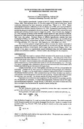
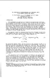
Figure 1 shows a cross section of a coke drum and illustrates<br />
how the coke is formed in the delayed coking operation. The drum is a<br />
large insulated vessel about 20 feet in diameter and 70 feet high. The<br />
coke is formed at the rate of about 2 feet per hour and proceedes to<br />
build up during a.24 hour cycle. The material at the bottom is fully<br />
polymerized and develops a porous structure through which gases and<br />
liquids can pass. The top layer in the cake drum is not fully poly-<br />
merized until it is subjected to heat for a prolonged period of time.
At the very top, some foam occurs. This foam subsides during the<br />
steaming and cooling cycle. It is important in filling the coke<br />
drum to avoid any carry over of foam or pitchy material into the<br />
vapor lines. Foam depressants are used to minimize the amount of<br />
foam (1). Level indicators are used to establish the position of<br />
the liquid or foam in the drum (2). These are operated by trans-<br />
mitting a beam from a radioactive source to an instrument mounted<br />
near the top of the drum. When the liquid reaches a predetermined<br />
level the feed to the drum is switched to an empty drum. At this<br />
time the full drum is steamed to remove light hydrocarbons and<br />
finally cooled by introducing water at the bottom of the drum.<br />
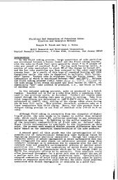
Factors affectinq Sizinq of Coke<br />
The coke is removed from the drum by means of high pressure<br />
water jets which operate on the principle used in hydraulic mining<br />
of coal (3). The procedure used in cutting the coke from the drum<br />
is extremely important. If it is not carried out properly the<br />
physical structure of the coke will be destroyed and the ultimate<br />
consumer would not have enough coarse particles to balance out their<br />
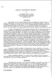
carbon aggregate formulation. The recommended procedure for cutting<br />
the coke is illustrated in Figure 2. This series of diagrams shows<br />
the steps which should be taken in order to get the maximum amount<br />
of lump coke needed for further processing.<br />
The first step is to bore a pilot hole. During this operation<br />
the fine cuttings are held in the upper section of the drum until the<br />
hole is completely through the bottom. At this time, all of the<br />
center cuttings fall out of the drum together with the water used in<br />
cutting.<br />
The drill stem is raised to the top and the bit is changed to<br />
a cutting head which has nozzles directed in a horizontal manner.<br />
The pilot hole is enlarged so that lumps of dislodged coke can fall<br />
freely through the opening. This avoids the danger of a coke build<br />
up around the drill stem which would prevent the rotation of the<br />
cut t ing head.<br />
Once the pilot hole is enlarged the stem is raised to the<br />
level of the coke in the drum. The operator can tell by the sound<br />
of the water hitting the metal walls when the top is reached. At<br />
this time the stem is lowered 3 - 4 feet below the. top. It is held<br />
in this position for several minutes until the coke is undercut.<br />
Then the stem is raised and lowered rapidly within this section until<br />
the coke is all cut from this layer. This action causes the coke to<br />
collapse from the drum walls resulting in large pieces which fal.1<br />
through the pilot hole. This operation is repeated until the drum<br />
is completely empty. In general, the decoking operation requires<br />
about 3 to 4 hours depending on the hardness of the coke. The harder<br />
I<br />
I<br />
I
the coke the more time required.<br />
123<br />
Lump coke in the size range of baseballs to footballs can<br />
be handled easily in conventional conveying systems. At the calcining<br />
plant all coke is run through a roll crusher set at an<br />
opening of 4 inches before it is fed to the kiln. The tumbling<br />
action in the kiln results in further degradation so that the final<br />
product all passes a 1 inch screen with approximately 35 to 40% retained<br />
on a 6 inch screen.<br />
Procedures to avoid Contamination<br />
There are several systems used in handling coke after it is<br />
discharged from the drum. These are as follows:<br />
A. The coker is mounted over a railroad track so that coke<br />
can be discharged directly into open hopper cars or gon-<br />
dola cars.<br />
B. A roll crusher is placed below the drum on small tracks.<br />
. This breaks up the large lumps to a size which will permit<br />
a coke slurry to be transported by pumping through a pipe<br />
line.<br />
C. The coke is directed to a ramp which leads to a pit. The<br />
pit may or may not contain water for further cooling of<br />
the coke.<br />
In each of the'above systems it is necessary to provide €or<br />
the recovery of water used in cutting. The areas around the coking<br />
unit should be paved. Curbs and retaining walls should be provided<br />
to contain any coke spillage.<br />
The drainage around the coker must be<br />
carefully planned to avoid sand. clay and gravel from entering the<br />
system. Drainage from rainstorms should be directed away from the<br />
coking unit.<br />
Transportinq and Convwinq Coke<br />
The freight cars used to transport the coke should be clean.<br />
Any sand. gravel or iron rust will contaminate the coke. The cars<br />
should be carefully inspected before loading.<br />
When coke is unloaded at the calcining plant, it is either<br />
conveyed directly to a storage silo or to an outdoor storage. When<br />
outdoor storage is necessary, it is preferable to provide paved<br />
areas to minimize contamination. The activities in the surrounding<br />
area can also affect the purity of the coke. For example, unloading<br />
of iron ore in the vicinity will contaminate the coke pile under
certain wind conditions.<br />
124<br />
Magnetic separators are used at the calcining plants.<br />
These will remove scrap iron from green coke, but will not remove<br />
iron rust, since the latter is non-magnetic. During calcining any<br />
iron oxide (rust) will be reduced to iron which can be removed from<br />
the calcined petroleum coke with magnets.<br />
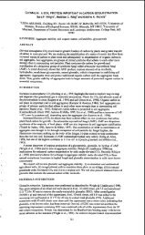
Chemical Composition of Petroleum Coke<br />
Green petroleum coke from the delayed coking process is<br />
essentially a hydrocarbon. The chemical composition as obtained<br />
by an ultimate analysis is given in Table I. Before it can be used<br />
as a carbon aggregate it is necessary to convert the green coke into<br />
elemental carbon by a petrochemical process. This is carried out<br />
by a pyrolytic treatment at temperatures around 2300 F. In this<br />
operation the carbon is not developed until hydrogen is chemically<br />
removed by thermal decomposition. In the trade this process is re-<br />
ferred to as calcination, but it is essentially a dehydrogenation<br />
reaction which converts a hydrocarbon into elemental carbon as in-<br />
dicated in Table I.<br />
A number of changes in basic properties and structure are<br />
brought about by the removal of chemically bound hydrogen from the<br />
hydrocarbons in order to produce elemental carbon. Some of these<br />
are as follows:<br />
A. The real density of green petroleum coke is 1.30. After<br />
calcining the real density is 2.07.<br />
B. Green petroleum coke is an electrical insulator whereas<br />
elemental carbon (calcined petroleum coke) is an electrical<br />
conductor. For example:<br />
Electrical Resistivity of Green Petroleum coke is 9 x<br />
lo6 ohm-inches.<br />
Electrical Resistivity of Calcined Petroleum coke is<br />
.03 5 ohm-inches .<br />
C. There are corresponding changes in the X-ray diffraction<br />
pattern.<br />
While there are profound changes occurring during the chemical<br />
conversion of green petroleum coke to elemental carbon, the mineral<br />
matter as indicated by the ash content remains essentially unchanged.<br />
The composition of the ash is important as this will affect the type<br />
of aluminum metal which can be produced.<br />
0
125<br />
The metallic components which are present in the crude oil<br />
will be carried over into the coke,. Materials such as vanadium<br />
and nickel occur in crude oils in varying amounts depending on the<br />
area of origin. There is actually very little if any iron or<br />
silicon in crude oil. Iron which is found in petroleum coke comes<br />
primarily from corrosion of the pipes and vessels used to process<br />
the crude oil. Additional iron finds its way into the coke in the<br />
form of rust from rail cars and conveying equipment. Silicon can<br />
come from the catalyst used in refining also from sand or gravel<br />
contamination.<br />
Iron and Silicon in Calcined Petroleum Coke<br />
The iron in calcined petroleum coke w ill normally range<br />
between .01 and .06%. The silicon content will range between .01<br />
and .OS. Table I1 shows the car analysis of iron and silicon in<br />
calcined petroleum coke all loaded from the same storage silo.<br />
The samples were taken from a conveyor belt with an automatic<br />
sampler. In this group of cars, we find some individual cars with<br />
iron as low as .019% and silicon as low as .010%. This information<br />
is useful to the carbon plant superintendent of a prebaked plant.<br />
If he is.required to supply anodes which are low in iron or silicon,<br />
he .can select the cars from a given shipment and segregate the low<br />
ash material in a separate area of his storage shed.<br />
Since the iron in calcined coke is magnetic, further re-<br />
moval can be accomplished at the consumers' plant by using magnetic<br />
separators. This will be most effective if applied after the<br />
grinding operation since iron pick up does take place in equipment<br />
such as the ball mill.<br />
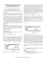
Several aluminum plants are now asking for a special grade<br />
of carbon with very low silicon. This is a difficult requirement<br />
to control at an ordinary calcining plant. However, a substantial<br />
improvement can be accomplished by screening the coke and using the<br />
coarse- fraction for the low silicon application. An example of the<br />
degree of improvement which can be achieved by this method is shown<br />
in Table 111. The silicon bearing material is concentrated in the<br />
fines (minus f"). The plus f" fraction contains only 40% of the<br />
total silicon or .008%.
SUMMARY<br />
In summarizing the information just presented, we find<br />
that a reasonable amount of care should be exercised at each step<br />
of handling petroleum coke. It is recongnized that some of the<br />
physical properties (sizing) of a calcined coke can be destroyed<br />
if the cutting operation is not carried out properly. .Also sources<br />
of contamination should be avoided in order to keep the iron and<br />
silicon content within required limits. Where a carbon aggregate<br />
with low silicon or low iron is required a selection can be made<br />
from a given shipment if the material is delivered in rail cars.<br />
References<br />
1. Tramell, W. D., Glaser, D., Oil and Gas Journal p. 65,<br />
June 5, 1961.<br />
2. Wright, P. G., Oil and Gas Journal p. 93 - 94. Aug. 11, 1958.<br />
3. Maas, R., Lauterbach, R. E., Petroleum Engineer p. 110 - 124,<br />
Feb. 1947.<br />
. .
127<br />
10 PSIG.<br />
VAPOR<br />
IOFTI ' FROTH<br />
I<br />
VAPOR<br />
OUT<br />
Figure 1.
128<br />
><br />
t<br />
5<br />
Y<br />
E<br />
3<br />
K<br />
n<br />
I<br />
I<br />
I
I<br />
TYPICAL ULTIMATE ANALYSIS OF<br />
GREEN <strong>PETROLEUM</strong> <strong>COKE</strong> AND CALCINED <strong>PETROLEUM</strong> <strong>COKE</strong><br />
Green Calcined<br />
Petroleum Coke Petroleum Coke<br />
(Polymerized Residual) (Pure Carbon)<br />
CARBON 91-80 98.40<br />
HYDROGEN 3.82 0.14<br />
OXYGEN 1.30 0.02<br />
NITROGEN 0.95 0.22<br />
SULFUR 1.29 1.20<br />
ASH 0.35 0.35<br />
CARBON-HYDROGEN RATIO 24 910<br />
TABLE II<br />
ANALYSIS OF CALCINED <strong>COKE</strong> SHIPMENTS<br />
CARS LOADED FROM PRODUCT SILO<br />
. ORDER OF LOADING ASH IRON SILICON<br />
CAR NO. % % %<br />
1<br />
2<br />
3<br />
4<br />
5<br />
6<br />
7<br />
8<br />
9<br />
10<br />
Run of Kiln<br />
.24<br />
.21<br />
.40<br />
.42<br />
.34<br />
.24<br />
-23<br />
.33<br />
.41<br />
.26<br />
TABLE 111<br />
EFFECT OF SCREENING<br />
ON SILICON CONTENT OF<br />
CALCINED <strong>PETROLEUM</strong> <strong>COKE</strong><br />
.019 .010<br />
-021 .012<br />
.065 .028<br />
.073 .022<br />
.043 -025<br />
-030 .010<br />
.020 .015<br />
-035 .025<br />
-065 .015<br />
.041 .021<br />
SIZE % SILICON<br />
Plus % Inch Fraction<br />
Minus % Inch Fraction<br />
.021<br />
.008<br />
.022