Rules of Golf 2012-2015 Pocket Edition - The R&A
Rules of Golf 2012-2015 Pocket Edition - The R&A Rules of Golf 2012-2015 Pocket Edition - The R&A
156 Appendix II b. Impact Area Roughness and Material Except for markings specified in the following paragraphs, the surface roughness within the area where impact is intended (the “impact area”) must not exceed that of decorative sandblasting, or of fine milling (see Fig. X). The whole of the impact area must be of the same material (exceptions may be made for clubheads made of wood). c. Impact Area Markings If a club has grooves and/or punch marks in the impact area they must meet the following specifications: (i) Grooves • Grooves must be straight and parallel. • Grooves must have a symmetrical cross-section and have sides which do not converge (see Fig. XI). Fig. XI ������� �������� Fig. X Illustrative impact area ������������ ������������ ������������ ������������ ��� ���������� ���������� ���������� �������������� • *For clubs that have a loft angle greater than or equal to 25 degrees, grooves must have a plain cross-section. • The width, spacing and cross-section of the grooves must be consistent throughout the impact area (some exceptions may be made for woods). • The width (W) of each groove must not exceed 0.035 inches (0.9 mm), using the 30 degree method of measurement on file with the R&A. ���
Appendix II 157 • The distance between edges of adjacent grooves (S) must not be less than three times the width of the grooves, and not less than 0.075 inches (1.905 mm). • The depth of each groove must not exceed 0.020 inches (0.508 mm). • *For clubs other than driving clubs, the cross-sectional area (A) of a groove divided by the groove pitch (W+S) must not exceed 0.0030 square inches per inch (0.0762 mm 2/mm) (see Fig. XII). Fig. XII • Grooves must not have sharp edges or raised lips. • *For clubs that have a loft angle greater than or equal to 25 degrees, groove edges must be substantially in the form of a round having an effective radius which is not less than 0.010 inches (0.254 mm) when measured as shown in Fig. XIII, and not greater than 0.020 inches (0.508 mm). Deviations in effective radius within 0.001 inches (0.0254 mm) are permissible. Fig. XIII A W + S < 0.0030in 2 / in 30° 30° �������� ������ ���������� �������������� (ii) Punch Marks • The maximum dimension of any punch mark must not exceed 0.075 inches (1.905 mm). • The distance between adjacent punch marks (or between punch marks and grooves) must not be less than 0.168 inches (4.27 mm), measured from centre to centre.
- Page 113 and 114: Rule 30 105 d. Penalty to Side A si
- Page 115 and 116: Rule 31 107 If the wrong ball belon
- Page 117 and 118: Rule 32 109 In handicap bogey, par
- Page 119 and 120: Rule 32 111 The Committee may, in s
- Page 121 and 122: (iii) ground under repair, and (iv)
- Page 123 and 124: Rule 33 / 34 115 33-7. Disqualifica
- Page 125 and 126: Rule 34 117 If the dispute or doubt
- Page 127 and 128: Appendix I 119 a. Relief for Embedd
- Page 129 and 130: Appendix I 121 3. Areas of the Cour
- Page 131 and 132: Appendix I 123 1. Water Hazards; Ba
- Page 133 and 134: Appendix I 125 Note: The Committee
- Page 135 and 136: Appendix I 127 water hazard, the pl
- Page 137 and 138: Appendix I 129 Note: “Closely-mow
- Page 139 and 140: Appendix I 131 The ball must be lif
- Page 141 and 142: Appendix I 133 The ball may be clea
- Page 143 and 144: Appendix I 135 4. Grass-covered cab
- Page 145 and 146: Part C Conditions of the Competitio
- Page 147 and 148: Appendix I 139 Note: If a ball of a
- Page 149 and 150: Appendix I 141 The signal for suspe
- Page 151 and 152: Appendix I 143 10. How to Decide Ti
- Page 153 and 154: Appendix I 145 General Numerical Dr
- Page 155 and 156: Appendix II 147 1. Clubs a. General
- Page 157 and 158: Fig. III Back 10º Max 20º Max Fac
- Page 159 and 160: Appendix II 151 Exception for Putte
- Page 161 and 162: Appendix II 153 • features that e
- Page 163: Appendix II 155 For traditionally s
- Page 167 and 168: Appendix III - The Ball Appendix II
- Page 169 and 170: Appendix IV 161 A “plain” glove
- Page 171 and 172: Rules of Amateur Status Amateur Sta
- Page 173 and 174: Amateur Status 165 Preamble The R&A
- Page 175 and 176: Rule 1 Amateurism Amateur Status 16
- Page 177 and 178: Amateur Status 169 (ii) the contrac
- Page 179 and 180: Amateur Status 171 b. Multiple Awar
- Page 181 and 182: Amateur Status 173 e. Invitation Un
- Page 183 and 184: Amateur Status 175 financial gain,
- Page 185 and 186: Amateur Status 177 Rule 8 Procedure
- Page 187 and 188: Amateur Status 179 e. Status While
- Page 189 and 190: Amateur Status 181 Unacceptable For
- Page 191 and 192: Index 183 cleaning [Rule 21] ......
- Page 193 and 194: Index 185 Bogey Competitions breach
- Page 195 and 196: Index 187 College Teams — expense
- Page 197 and 198: Index 189 sharing of distance infor
- Page 199 and 200: Index 191 Gambling — policy on ..
- Page 201 and 202: Index 193 determining score for whe
- Page 203 and 204: Index 195 out of bounds, used to de
- Page 205 and 206: Index 197 winner of hole [Rule 2-1]
- Page 207 and 208: Index 199 Out of Bounds. See also O
- Page 209 and 210: Index 201 local rule [App. I] .....
- Page 211 and 212: Index 203 from teeing ground [Rule
- Page 213 and 214: Index 205 cancelling [Rule 10-1c] .
Appendix II 157<br />
• <strong>The</strong> distance between edges <strong>of</strong> adjacent grooves (S) must not be less<br />
than three times the width <strong>of</strong> the grooves, and not less than 0.075<br />
inches (1.905 mm).<br />
• <strong>The</strong> depth <strong>of</strong> each groove must not exceed 0.020 inches (0.508 mm).<br />
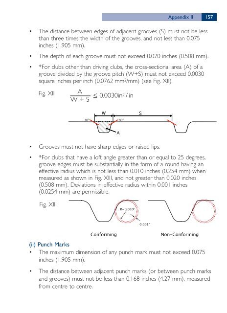
• *For clubs other than driving clubs, the cross-sectional area (A) <strong>of</strong> a<br />
groove divided by the groove pitch (W+S) must not exceed 0.0030<br />
square inches per inch (0.0762 mm 2/mm) (see Fig. XII).<br />
Fig. XII<br />
• Grooves must not have sharp edges or raised lips.<br />
• *For clubs that have a l<strong>of</strong>t angle greater than or equal to 25 degrees,<br />
groove edges must be substantially in the form <strong>of</strong> a round having an<br />
effective radius which is not less than 0.010 inches (0.254 mm) when<br />
measured as shown in Fig. XIII, and not greater than 0.020 inches<br />
(0.508 mm). Deviations in effective radius within 0.001 inches<br />
(0.0254 mm) are permissible.<br />
Fig. XIII<br />
A<br />
W + S<br />
< 0.0030in 2 / in<br />
30° 30°<br />
��������<br />
������<br />
���������� ��������������<br />
(ii) Punch Marks<br />
• <strong>The</strong> maximum dimension <strong>of</strong> any punch mark must not exceed 0.075<br />
inches (1.905 mm).<br />
• <strong>The</strong> distance between adjacent punch marks (or between punch marks<br />
and grooves) must not be less than 0.168 inches (4.27 mm), measured<br />
from centre to centre.


