oxygenated fuel strategies to combat air pollution - Argonne ...
oxygenated fuel strategies to combat air pollution - Argonne ...
oxygenated fuel strategies to combat air pollution - Argonne ...

Create successful ePaper yourself
Turn your PDF publications into a flip-book with our unique Google optimized e-Paper software.
OXYGENATED FUEL STRATEGIES TO COMBAT AIR POLLUTION<br />
A FEDERAL OVERVIEW<br />
David J. Kortum and Meredith G. Miller<br />
Field Operations and Support Division 64065<br />
U. S. Environmental Protection Agency<br />
Washing<strong>to</strong>n, DC 20460<br />
Keywords: oxygenate, <strong>pollution</strong>, MTBE<br />
INTRODUCTION:<br />
The use of oxygenate <strong>fuel</strong> additives in gasoline as a strategy <strong>to</strong><br />
decrease dangerous ambient <strong>air</strong> levels of pollutants, especially<br />
carbon monoxide (CO), has recently expanded dramatically. Two<br />
especially significant programs <strong>to</strong> <strong>combat</strong> <strong>air</strong> <strong>pollution</strong> were<br />
required under the 1990 amendments <strong>to</strong> the Clean Air Act: the<br />
carbon monoxide <strong>oxygenated</strong> <strong>fuel</strong>s program and the reformulated<br />
gasoline program. This paper explores the legislative and<br />
statu<strong>to</strong>ry his<strong>to</strong>ry of oxygenate use in gasoline and oxygenatebased<br />
<strong>pollution</strong> abatement programs, proyram implementation<br />
problems and public reaction, health research on oxygenates and<br />
the resulting changes in ambient <strong>air</strong> quallity for cities which<br />
have instituted programs.<br />
STATUTORY BACKGROUND /<br />
Section 211(m) of the Clean Air Act as amended in 1990 (the Act<br />
or CAA) requires states with areas experiencing dangerous levels<br />
of carbon monoxide <strong>pollution</strong> <strong>to</strong> implement winter <strong>oxygenated</strong><br />
gasoline programs no later than November 1, 1992. This mandate<br />
is applicable <strong>to</strong> 39 areas throughout the country, although just<br />
36 began the program on November 1, 1992.<br />
The <strong>oxygenated</strong> gasoline program requires gasoline in the<br />
specified control areas <strong>to</strong> contain an average of 2.7% oxygen by<br />
weight during that portion of the year in which the areas are<br />
prone <strong>to</strong> high ambient concentrations of CO, typically during tne<br />
core winter months. The lengths of these control periods have<br />
been established by the EPA Administra<strong>to</strong>r. The Act requires that<br />
the winter <strong>oxygenated</strong> gasoline program apply <strong>to</strong> all gasoline sold<br />
or dispensed in the larger of the Consolidated Metropolitan<br />
Statistical Area (CMSA) or the Metropolitan Statistical Area<br />
(MSA) in which the nonattainment area is located. (See Table 1<br />
below for a complete list of the CMSAs and MSAs affected by this<br />
requirement and their control periods.)<br />
Just a few states opted <strong>to</strong> allow averaging programs, including<br />
Pennsylvania and Ohio. Other states, such as Oregon and<br />
Washing<strong>to</strong>n. have adopted limited averaging scenarios, allowing<br />
individual companies <strong>to</strong> average their oxygen contents over the<br />
course of the season, but not allowing companies <strong>to</strong> sell and<br />
trade credits among themselves. The majority of the states<br />
adopted programs which did not allow for averaging, thus<br />
requiring that & gallon of gasoline contain no less than the<br />
minimum 2.7% oxygen by weight.<br />
267
~ ~ ~<br />
Table 1: Program Areas<br />
November 1 - February 29<br />
Hartford-New Britain-<br />
Middle<strong>to</strong>wn, CT CMSA<br />
Seattle-Tacoma, WA CMSA<br />
Philadelphia-Wilming<strong>to</strong>n-Tren<strong>to</strong>n,<br />
PA-NJ-DE-MD CMSA<br />
Greensboro-Wins<strong>to</strong>n-Salem-<br />
High Point, NC MSA<br />
Raleigh-Durham, NC MSA<br />
El Paso, TX MSA<br />
Denver-Boulder, CO CMSA<br />
San Diego, CA MSA<br />
Washing<strong>to</strong>n, DC-MD-VA MSA<br />
Grant's Pass, OR<br />
Baltimore, MD MSA<br />
Medford, OR MSA<br />
Missoula, MT<br />
Klamath County, OR<br />
Provo-Orem, UT MSA<br />
Albuquerque, NM MSA<br />
Colorado Springs, CO MSA<br />
Fort Collins-Loveland, CO MSA<br />
Portland-Vancouver, OR-WA CMSA<br />
New York-Northern New Jersey-Long<br />
Island, NY-NJ-CT CMSA<br />
Minneapolis-St. Paul, MN-WI MSA Chico, CA MSA<br />
Fresno, CA MSA<br />
Reno, NV MSA<br />
Modes<strong>to</strong>, CA MSA<br />
Sacramen<strong>to</strong>, CA MSA<br />
San Francisco-Oakland-San Jose, CA CMSA S<strong>to</strong>ck<strong>to</strong>n, CA MSA<br />
-9<br />
Las Vegas, NV MSA<br />
Los Angeles-Anaheim-Riverside, CA CMSA<br />
September 1 - February 29 Spokane, WA MSA<br />
Phoenix, A2 MSA<br />
Under authority set forth in another part of the Act, the<br />
Administra<strong>to</strong>r promulgated labeling regulations for the sale of<br />
gasoline at retail gasoline stations in <strong>oxygenated</strong> gasoline<br />
control areas. Under the Agency's regulation, the gasoline pumps<br />
at retail stations in each control area must be labeled during<br />
the applicable control period with conspicuous labels.<br />
labels must be clearly readable in order <strong>to</strong> provide the public<br />
with information that <strong>oxygenated</strong> gasoline is being dispensed.<br />
Under section 211(k) of the Act, l'reformulated gasoline" is<br />
required in certain ozone nonattainment areas beginning in 1995.<br />
Among other things reformulated gasoline requires at least 2.0<br />
percent oxygen by weight throughout the year. Reformulated<br />
gasoline could represent as much as half of the gasoline'utilized<br />
in the U.S. depending upon the number of states that decide <strong>to</strong><br />
adopt the program. (Although some areas are required <strong>to</strong> adopt<br />
the program, other less severe ozone nonattainment areas can I<strong>to</strong>pt<br />
in<strong>to</strong>" the program. )<br />
268<br />
The
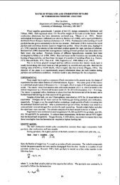
The program-generated demand, on a yearly basis, for oxygenates<br />
can be seen in Figure 1.<br />
II<br />
F lgure 1 : Oxygenate Program Demand<br />
ENVIRONMENTAL BENEFITS OF OXYGENATED FUELS<br />
Carbon monoxide (CO) is a colorless, odorless gas which can cause<br />
central nervous system effects such as a reduction in visual<br />
perception and manual dexterity, decreased exercise performance,<br />
and among individuals with chronic heart disease, a marked<br />
decrease in physical capacity and increase in chest pain. Mo<strong>to</strong>r<br />
vehicles are significant contribu<strong>to</strong>rs <strong>to</strong> carbon monoxide<br />
emissions nationwide, adding approximately 75 percent <strong>to</strong> the CO<br />
inven<strong>to</strong>ry in major metropolitan areas. Millions of U.S. citizens<br />
are exposed <strong>to</strong> dangerous levels of this pollutant especially<br />
during the winter months.<br />
One important strategy which an area may utilize <strong>to</strong> reduce Co<br />
emissions is the implementation of a cleaner-burning <strong>oxygenated</strong><br />
gasoline program. For any given set of conditions, there is an<br />
optimum ratio of <strong>fuel</strong> <strong>to</strong> oxygen or <strong>air</strong> which provides the most<br />
efficient combustion. In cold weather when combustion tends <strong>to</strong><br />
be less efficient, extra oxygen enhances combustion by offsetting<br />
<strong>fuel</strong>-rich operating conditions, especially during vehicle<br />
starting. If oxygen is added <strong>to</strong> the <strong>fuel</strong> in the form of<br />
oxygenates, a second source of oxygen becomes available (in<br />
addition <strong>to</strong> the primary source from the <strong>air</strong>).<br />
A gasoline blend<br />
containing 2 .7 percent oxygen, by weight, will result in a 15% <strong>to</strong><br />
20% reduction in CO emissions, on a mile-for-mile basis, when<br />
compared <strong>to</strong> gasoline not containing oxygenates.<br />
269
Oxygenates also cause decreases in unburned hydrocarbon exhaust<br />
emissions including certain <strong>to</strong>xic <strong>air</strong> pollutants such as benzene<br />
and 1,3-butadiene. Although oxygenates do increase aldehyde<br />
emissions, <strong>to</strong>tal <strong>to</strong>xic emissions decrease through oxygenate use.<br />
WHAT OXYGENATES ARE USED?<br />
Alcohols and ethers have been added <strong>to</strong> gasoline in various forms<br />
for over fifteen years, sometimes <strong>to</strong> enhance octane, sometimes<br />
simply as a <strong>fuel</strong> extender, and, more recently, <strong>to</strong> decrease<br />
emissions. Typically, although other oxygenates could be<br />
utilized (and have been in the past), <strong>fuel</strong> oxygen is added <strong>to</strong><br />
gasoline in the form of ethanol, an alcohol, or methyl tertiary<br />
butyl ether (MTBE).' These oxygenates are used because they are<br />
the most economically viable in <strong>to</strong>day's <strong>fuel</strong> market. Ethanol has<br />
been traditionally added <strong>to</strong> gasoline at 10 percent by volume,<br />
which adds approximately 3.5 percent oxygen <strong>to</strong> the <strong>fuel</strong>.<br />
However, in oxy<strong>fuel</strong> program areas, ethanol is often added at<br />
about 7.7 percent by volume <strong>to</strong> meet the program requirement of<br />
2.7 percent oxygen. TO reach the same oxygen level, MTBE is<br />
added at a level of approximately 15 percent by volume.<br />
PROGRAM RESULTS<br />
The previously stated 15 <strong>to</strong> 20 percent reduction in CO emissions<br />
is evidenced by what occurred last year in the cities which<br />
implemented an <strong>oxygenated</strong> <strong>fuel</strong>s program. A preliminary study of<br />
exceedances of the National Ambient Air Quality Standard for<br />
carbon monoxide in these cities covering the winter months in the<br />
1992-93 season during which an <strong>oxygenated</strong> <strong>fuel</strong>s program was in<br />
place reveals a very telling picture. (See Figure 2.) For 21<br />
areas which had not previously implemented <strong>oxygenated</strong> <strong>fuel</strong>s<br />
programs, CO exceedances dropped by 95 percent when compared <strong>to</strong><br />
the previous winter (1991-92). In California, where a program<br />
was implemented requiring slightly less <strong>to</strong>tal oxygen (2.0 percent<br />
oxygen instead of 2.7 percent - equivalent <strong>to</strong> about 11 percent<br />
MTBE instead of 15 percent), exceedances dropped by 80 percent.<br />
In areas with pre-existing programs, most of which required<br />
oxygen levels around 2.0 percent but, under the new program,<br />
increased <strong>to</strong> 2.7 percent, exceedances dropped by about 50<br />
percent. Although normal year-<strong>to</strong>-year variations in<br />
meteorological conditions or patterns of vehicle use might have<br />
contributed <strong>to</strong> the decline in CO exceedances in some<br />
nonattainment areas, these aggregate national data suggest<br />
strongly that MTBE is having the kind of positive effect overall<br />
that was intended.<br />
' Other oxygenates which can be used include tertiary amyl<br />
methyl ether (TAME) and ethyl tertiary butyl ether (ETBE), both<br />
of which have been used <strong>to</strong> a very small extent during the past<br />
season in some isolated cases.<br />
In the past certain blends of<br />
methanol and other alcohols have been used but these blends are<br />
not viable in <strong>to</strong>day's market.<br />
270 P
Figure 2-<br />
FIRST YEAR PROGRAM RESULTS<br />
X Program compliance was excel lent in first season.<br />
X Comparlson of data from this wlnter <strong>to</strong> data from last wlnter shc<br />
an 80% reductlon In CO exceedances.<br />
HEALTH ISSUES<br />
Citizens in some areas of the country complained of acute health<br />
symp<strong>to</strong>ms such as headache and nausea which they associated with<br />
use of MTBE in gasoline. There are a number of reasons why this<br />
reaction <strong>to</strong> MTBE-blended gasoline was unexpected. MTBE has been<br />
used in the U.S. as an octane enhancer since the late 1970's (at<br />
concentrations of 2-11%). Industry had tested many aspects of<br />
the <strong>fuel</strong> additive prior <strong>to</strong> 1992 and this research indicated no<br />
significant health concerns. Seven cities had, in fact, required<br />
wintertime use of <strong>oxygenated</strong> gasoline prior <strong>to</strong> 1992, most notably<br />
Denver which began its program in 1988, and experienced no<br />
problems similar <strong>to</strong> those in Alaska. Under the Clean Air Act<br />
<strong>oxygenated</strong> gasoline program, however, concentrations of MTBE must<br />
be generally higher than they were in Denver. (Denver required<br />
MTBE concentrations from 10-14.4%, while the Act requires 15%.)<br />
The Environmental Protection Agency (EPA) <strong>to</strong>ok these concerns<br />
seriously and, in a very short time, organized a comprehensive<br />
strategy <strong>to</strong> investigate Alaska's complaints. In order <strong>to</strong> address<br />
the issue of health symp<strong>to</strong>ms associated with acute exposures <strong>to</strong><br />
271
MTBE-blended gasoline, EPA outlined a six-month test program in<br />
January 1993. EPA coordinated almost $2 million worth of<br />
studies, working with the Centers for Disease Control and<br />
Prevention (CDC), the State of Alaska, industry groups<br />
represented by the American Petroleum Institute (API) and the<br />
Oxygenated Fuels Association (OFA), as well as other EPA and<br />
state offices.<br />
The testing effort included animal studies, human clinical<br />
studies, epidemiological studies, exposure studies and au<strong>to</strong>mobile<br />
emissions studies and <strong>air</strong> and <strong>fuel</strong> sampling. In addition, ORD<br />
accelerated its review of existing research on chronic effects of<br />
MTBE. The results from these studies were presented at a<br />
workshop, sponsored by ORD, API and OFA, on July 26-28, 1993.<br />
The workshop enabled EPA and others <strong>to</strong> assess these health<br />
concerns before the start of the <strong>oxygenated</strong> gasoline season in<br />
1993 in Alaska and elsewhere. EPA's assessment of the potential<br />
health risks associated with MTBE-<strong>oxygenated</strong> gasoline has been<br />
completed and indicates that MTBE appears <strong>to</strong> have very little<br />
acute health risk <strong>to</strong> healthy people under relatively temperate<br />
conditions. Hence, in terms of short-term acute health effects,<br />
these results seem <strong>to</strong> provide no basis <strong>to</strong> question continuing the<br />
overall MTBE oxy<strong>fuel</strong>s program. This conclusion does not reflect<br />
that there may be a particularly sensitive subpopulation which<br />
may react <strong>to</strong> MTBE differently. However, results <strong>to</strong> date provide<br />
no firm evidence that such sensitive individuals exist or, if<br />
they do, how they might be identified. Further research on<br />
exposure <strong>to</strong> MTBE and the health effects of MTBE continues.<br />
CONCLUSION:<br />
Available data indicate that <strong>oxygenated</strong> <strong>fuel</strong>s program implemented<br />
for <strong>pollution</strong> abatement have successfully decreased exceedences<br />
of the National Ambient Air Quality Standards for carbon monoxide<br />
<strong>pollution</strong>. Health research appears <strong>to</strong> indicate little health<br />
risk <strong>to</strong> healthy people under relatively temperate conditions.<br />
212
Keywords: Emissions, Oxygenates, Fuels<br />
SYMPOSIUM ON OXYGENATES AS FUEL ADDITIVES<br />
AMERICAN CHEMICAL SOCIETY, FUEL DIVISION<br />
SAN DlEGO NATIONAL MEETING<br />
MARCH 13 -18, 1994<br />
FUTURE FUEL DIVERSIFICATION WITH OXYGENATES<br />
William J. Piel<br />
ARC0 Chemical Company<br />
3801 West Chester Pike<br />
New<strong>to</strong>wn Square, Pa 19073<br />
INTRODUCTION<br />
Fuel oxygenate blending in mo<strong>to</strong>r <strong>fuel</strong>s first became commercialize in 1969 with the blending of butyl<br />
alcohol in gasoline. This first <strong>fuel</strong> alcohol was made by adding oxygen <strong>to</strong> isobutanes. Now most of this<br />
alcohol production is converted <strong>to</strong> isobutylene for methyl tertiary butyl ether (MTBE) production. MTBE<br />
blending was first commercialized in the US. in 1979 when the U.S. EPA granted a section 21 1F<br />
waiver request <strong>to</strong> blend it in<strong>to</strong> unleaded gasoline. MTBE use grew during the 1980s as a high octane<br />
replacement for lead compounds in gasoline. Similarly, 10% ethanol blending was approved in 1978.<br />
With a government tax incentive for alcohols made from renewable sources, ethanol's use also grew as<br />
a non-petroleum gasoline extender in the mid-1980s.<br />
Relative <strong>to</strong> mobile source emissions, the 1990 revision <strong>to</strong> the Clean Air Act (CAA) requires reductions of<br />
carbon monoxide (CO), volatile organic compounds (VOCs). and <strong>to</strong>xics from gasoline <strong>fuel</strong>ed vehicles.<br />
Reductions in nitrogen oxides (NOx) and greenhouse gases (such as carbon dioxide - C02) were not<br />
required. The strategy in the CAA <strong>to</strong> decrease ground level ozone is by reducing VOC mass emissions<br />
by 15% in 1995 and 25% in 2000. The other attributing compound <strong>to</strong> ozone, NOx emissions, are only<br />
capped at the 1990 levels in the CAA. Based on the predictive models developed by the US. EPA and<br />
by the California Air Resource Board (CARB), it appears that the <strong>fuel</strong> reformulation will be able <strong>to</strong><br />
achieve the year 2000 performance requirements targeted in the CAA.<br />
Fuel oxygenates played a key role in both the Oxygenated Fuels and Reformulated Fuels outlined in the<br />
CAA. The next wave of environmental interest is <strong>to</strong> possibly modify mo<strong>to</strong>r <strong>fuel</strong>s andlor mo<strong>to</strong>r vehicles<br />
for reductions in NOx emissions and greenhouse gases such as C02. Fuel oxygenates can also play a<br />
significant role in such <strong>fuel</strong> modifications. To achieve the maximum emissions reduction potential,<br />
minor engine modifications may be required <strong>to</strong> take full advantage of the possible <strong>fuel</strong> property<br />
improvements.<br />
FUEL OXYGENATES<br />
Though MTBE and ethanol are the most commonly used oxygenates, there are many other potential<br />
<strong>fuel</strong> oxygenates that are being developed or investigated such as TAME (tertiary amyl methyl ether) and<br />
ETBE (ethyl tertiary butyl ethers)(Ref 1). The properties of these oxygenates and others are listed in<br />
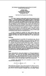
Table 1. The most useful property of the oxygenates is their high octane. Outside of metal<br />
compounds, oxygenates are generally the only high octane alternative <strong>to</strong> aromatics in gasoline. The<br />
potential octane contribution of oxygenates are shown in Figure 1 as a function of the their oxygen<br />
contribution in gasoline.<br />
While mixtures of alcohols are allowed up <strong>to</strong> 3.7 weight percent oxygen in gasoline under various EPA<br />
approved waivers, ethers are currently limited <strong>to</strong> 2.7 weight percent oxygen in gasoline. Under these<br />
limits, ethers can potentially add 3 <strong>to</strong> 4 octane numbers <strong>to</strong> the gasoline pool. If the oxygen limit for<br />
mixed ethers were raised <strong>to</strong> 3.7 percent, ethers could contribute 4 <strong>to</strong> 5 octane numbers ,and up <strong>to</strong> 20+<br />
volume percent <strong>to</strong> gasoline. Their potentially large octane and volume contribution can play a<br />
significant role in replacing most of the aromatics in gasoline, and modifying future gasoline formulations<br />
for reductions in NOx and C02 emissions as will be discussed later.<br />
Besides their octane, a major advantage of ethers over aromatics is their kelatively lower boiling<br />
temperatures. Since lead phasedown in gasoline. the increased use of aromatics in premium gasolines<br />
have lead <strong>to</strong> poor mid-range volatility and a degradation of cold engine driveability and performance(Ref<br />
2). The au<strong>to</strong>makers have been making an effort <strong>to</strong> limit this performance degradation by proposing a<br />
cap on a Driveability Index (DI) that is calculated from distillation temperatures of gasoline. Using their<br />
individual boiling temperatures, then DI differences between ethers and aromatics are illustrated in<br />
Figure 2. Though both provide octanes higher than a 100 (r+M)/2, the DI of most ethers are favorably<br />
lower while the high boiling temperatures of the aromatics contributed <strong>to</strong> higher DI for gasoline,<br />
particularly premium gasolines. The DI benefits of using ethers for octane is best illustrated by<br />
comparing the DI changes between the 1992 and 1993 winter DI averages for the <strong>oxygenated</strong> and non-<br />
<strong>oxygenated</strong> cities in the AAMA (American Au<strong>to</strong>mobile Manufacturers Association) gasoline surveys.<br />
273
Gasoline Grade<br />
DRIVEABILITY INDEX DI<br />
- 1992 lgg3 CHANGE<br />
Regular - Oxygenated 1112 1061 -53<br />
Non-ox ygenated 1071 1092 +21<br />
Premium - Oxygenated 1154 1087 -67<br />
Non-<strong>oxygenated</strong> 1153 1147 -6<br />
Though the non-<strong>oxygenated</strong> cities showed very little change in DI. the <strong>oxygenated</strong> cites (with<br />
predominately MTBE) showed very favorable decreases greater than 50 DI. Therefore, the use of<br />
ethers appears <strong>to</strong> provide an effective means for improving the mid-range volatility of the gasolines<br />
which should also benefit the 1990 CAA Reformulated Gasoline program.<br />
EXHAUST NOx EMISSIONS<br />
The work completed by AUTOIOIL established sulfur in gasoline as a major influence on tailpipe NOx<br />
because of its effect on the activity or efficiency of the catalytic conver<strong>to</strong>rs(Ref 3). However, the other<br />
<strong>fuel</strong> variables that effect NOx emissions were not quite as clear(Ref 4-5). Since NOx is a side reaction<br />
of combining oxygen and nitrogen during the combustion process, NOx in engine exhaust is expected <strong>to</strong><br />
be a function of the peck temperatures during combustion. The dilemma is what <strong>fuel</strong> property changes<br />
have the most influence on the peak combustion temperatures. Earlier research by others had found<br />
the flame temperature and resutting NOx emissions of <strong>fuel</strong>s <strong>to</strong> be most easily correlated with the<br />
hydrogen <strong>to</strong> carbon ratio (WC) of the <strong>fuel</strong> (Ref 6-8) where high WC has a lower flame temperature and<br />
therefore lower NOx thermal equilibriums.<br />
This relationship can also be seem in some more recent work conducted with ARC0 Chemical Europe<br />
in conjunction with BP Oil, and Voko. ECE emission test were conducted with 11 different <strong>fuel</strong>s of<br />
varying composition but relatively similar octanes in two 1991 non-cat cars with VOLVO engines (E-230<br />
2.3 litres, 4 cylinders). The relative change in the NOx emissions compared <strong>to</strong> each <strong>fuel</strong>'s hydrogen <strong>to</strong><br />
<strong>fuel</strong> ratio in this study is shown in Figure 3. Also, three of the <strong>fuel</strong>s contained oxygen, one from ethanol<br />
and two from MTBE. The data in Figure 3 suggest that the NOx emissions are strongly related <strong>to</strong> the<br />
fuek hydrogen <strong>to</strong> carbon ratio independent of oxygen content in the <strong>fuel</strong>. This correlation <strong>to</strong> WC ratio<br />
is consistent with the resuits reported in previously referenced studies.<br />
However, in addition <strong>to</strong> the flame temperature of the <strong>fuel</strong>, the ultimate combustion temperature would<br />
also be expected <strong>to</strong> be a function of the octane of the <strong>fuel</strong>. Octane is a good indica<strong>to</strong>r of the <strong>fuel</strong>'s<br />
resistance <strong>to</strong> au<strong>to</strong>ignite under the more severe operating conditions in the engine. Low octane <strong>fuel</strong> may<br />
au<strong>to</strong>ignite earty prior <strong>to</strong> optimum timing under severe engine conditions and thereby increase peak<br />
pressures and temperatures. Therefore, higher octane <strong>fuel</strong>s would be expected <strong>to</strong> suppress au<strong>to</strong>ignition<br />
and generate lower peak temperatures and lower NOx under severe engine operating conditions. The<br />
possible sensitivity of NOx <strong>to</strong> octane, particularly mo<strong>to</strong>r octane, of the <strong>fuel</strong> has been Observed in some<br />
previous studies(Ref 9-10),<br />
To test this theory that NOx production may be influenced by octane number independent of <strong>fuel</strong><br />
composition, the octane of a reference <strong>fuel</strong> was artificially lowered by adding minute amounts of tertiary<br />
butyl hydro peroxide (TBHP), a very powerful pro-knock compound. FTP emission tests were<br />
conducted on two cars (1991 Dodge Spirit 2.5 IiterfrBl and 1990 Ford Probe 2.2 IiterIPFI) using the<br />
reference <strong>fuel</strong> Ondolene) and the same <strong>fuel</strong> with two levels of peroxide. The average results for the two<br />
cars is as follows:<br />
TBHP Fuel Octane % NOx<br />
m W(R+M)R Chanaes<br />
0 88.7 93.0<br />
420 87.2 91.4<br />
1100 86.5 90.5<br />
Base<br />
+ 15%<br />
+ 14%<br />
These results support the theory that octane number, independent of <strong>fuel</strong> composition, can also effect<br />
NOx emissions in the engine exhaust. Evidence of this octane effect has also been seen in Ethyl<br />
Corporation's work with MMT (methylcyclopentadienyl manganese tricarbonyo, a metal based octane<br />
additive. In the emission work <strong>to</strong> support a MMT waiver request, <strong>fuel</strong>s containing 0.03125 grams of<br />
MMT per gallon increased the <strong>fuel</strong>'s octane by approximately 0.8 octane numbers, but more importantly<br />
decreased NOx emissions(Ref 11).<br />
A review of the emission resuns for AUTOIOIL's older car fleet shows similar <strong>fuel</strong> effects on the NOx<br />
emissions. Figure 4A shows the average NOx emissions relative <strong>to</strong> the <strong>fuel</strong>s' H/C ratio. The<br />
AUTOIOIL's <strong>fuel</strong> matrix essentially falk in<strong>to</strong> two groups: low HIC fuek and high WC fuek. The NOx<br />
emissions from the high WC fuek are approximately 12% lower than that from the low HIC <strong>fuel</strong>s. The<br />
data ako shows no oxygen effects since the emissions for the <strong>oxygenated</strong> <strong>fuel</strong>s appear <strong>to</strong> be evenly<br />
dispersed among the non-<strong>oxygenated</strong> <strong>fuel</strong>s. As Figure 4A shows, there ako is more variance in the<br />
low HIC <strong>fuel</strong> group than the high WC group. Much of this variance seems <strong>to</strong> be explained by the mo<strong>to</strong>r<br />
octane which varies as much as 5 octanes for the low HIC <strong>fuel</strong>s as shown in Figure 48. Though mo<strong>to</strong>r<br />
octane seems <strong>to</strong> explain some of the variance in the high HIC <strong>fuel</strong>s as well, it is not as clear since the<br />
range of mo<strong>to</strong>r octane is only 2.5 numbers for this group.<br />
214<br />
i<br />
i
The review of these studies suggest that much of the <strong>fuel</strong> effects on NOx emissions from gasoline<br />
vehicles can be explained by three main fac<strong>to</strong>rs: the WC ratio and the mo<strong>to</strong>r octane of the <strong>fuel</strong> as it<br />
effects peak combustion temperatures. and the <strong>fuel</strong>'s sulfur content for its effect on the catalyst activity<br />
in the Catalytic conver<strong>to</strong>r. One other <strong>fuel</strong> quality for investigation is the ability of the <strong>fuel</strong> <strong>to</strong> warm-up the<br />
engine quicker (with higher DI). end thereby increase <strong>to</strong>tal NOx over an emissions test cycle. However.<br />
this might offset by the catalytic conver<strong>to</strong>r also warming up quicker.<br />
CARBON DIOXIDES EMISSIONS<br />
Carbon dioxide (CO2) from <strong>fuel</strong> combustion is considered <strong>to</strong> be a major source of greenhouse gases,<br />
and the current administration is dedicated <strong>to</strong> capping the year 2000 greenhouse gases at the same<br />
level as 1990. Though the stationary power sources may have the flexibility <strong>to</strong> switch from high fossil<br />
carbon fuek such as coal or heavy oils <strong>to</strong> low fossil carbon <strong>fuel</strong>s such as natural gas or biomass <strong>fuel</strong>s<br />
es a way <strong>to</strong> reduce C02, transportation <strong>fuel</strong>s are not quite as flexibility. However. the C02 emissions<br />
associated with gasoline energy content is still related <strong>to</strong> the WC ratio of the <strong>fuel</strong> components as shown<br />
in Figure 5. Aromatics represent the highest carbon content <strong>fuel</strong>s and therefore the gasoline<br />
Components with the highest C02 per unit of energy. Ethers. like paraffins, are gasoline Components<br />
with the lowest C02 per unit of energy. Therefore. using ethers in place of aromatics for octane in<br />
gasoline may be an effecti~e way <strong>to</strong> reduce fossil carbon dioxide emissions from gasoline by 4 <strong>to</strong> 5<br />
percent. This C02 relationship <strong>to</strong> <strong>fuel</strong> WC is consistent with the analysis reported by the AUTOlOlL<br />
analysis (Ref 12).<br />
Raising the octane of gasoline presents another opportunity <strong>to</strong> significantly reduce C02 emissions from<br />
transportation fuek by allowing the au<strong>to</strong>makers <strong>to</strong> raise the compression ratios of the engines of their<br />
new car models. Increasing the compression ratio would reduce <strong>fuel</strong> consumption by increasing the<br />
thermal efficiency of the engine's operation. The optimum octane for gasoline was last debated in<br />
industry about two decades ago when unleaded gasoline was about <strong>to</strong> be widely distributed in the<br />
marketplace (Ref 13-21). The conclusion from most of these studies was that the optimum octane for<br />
unleaded gasoline was around 91 <strong>to</strong> 92 (R+M)R octane even though the industry went with 87 (R+M)R<br />
as the standard octane for gasoline. The economic basis used in these studies was generally limited <strong>to</strong><br />
comparing the cost of <strong>fuel</strong> savings versus the cost of raising the octane of gasoline. The environmental<br />
benefit of reducing C02 emissions was not considered in these studies at the time. If it had been<br />
included. it would have further supported the higher octane <strong>fuel</strong> I higher compression engine<br />
combination.<br />
Figure 6 shows typical relationships <strong>to</strong> engine compression ratio which is derived from one of these<br />
studies (Ref 15). In the range of interest. Figure 6 shows that increasing the compression ratio by two<br />
numbers would increase <strong>fuel</strong> efficiency by approximately 10 percent but would also increase engine's<br />
octane requirement by approximately 6 octane numbers. This study suggest that each octane is<br />
potentially worth 1.0 % increase in <strong>fuel</strong> efficiency or <strong>fuel</strong> economy. This ratio between efficiency and<br />
octane seems <strong>to</strong> be approximately the same in most of these studies.<br />
Some of these studies also attempted <strong>to</strong> address the issue on whether there was any increase in other<br />
emissions such as NOx or hydrocarbons(Ref 18-21). Their results suggested that there was little<br />
change in these emissions after re-optimizing other engine operating parameters such as timing and <strong>air</strong><br />
<strong>to</strong> <strong>fuel</strong> mixtures. However. these studies did not evaluate any possible emission reduction benefits<br />
associated with also raising the <strong>fuel</strong>'s octane for the higher compression ratio operation.<br />
What these prior studies did not review in their analysis is any possible loss in driveability performance<br />
associated with higher <strong>fuel</strong> octane, particularly if high boiling aromatics should be the main source of the<br />
octane increases. As mentioned earlier, this is now a major concern of the au<strong>to</strong>makers. Therefore, the<br />
source of increased octane would likely have <strong>to</strong> be from ethers which can potentially add five octane<br />
numbers <strong>to</strong> the gasoline pool with out worsening the driveability index of the gasoline.<br />
Another benefit of using ethers instead of aromatics for octane is their greater increase in combustion<br />
gas volumes. Higher HIC ratio <strong>fuel</strong>s generate more moles or volumes of product gases per volume of<br />
combustion <strong>air</strong> that is consumed or drawn in<strong>to</strong> the engine's cylinders. This higher volume of<br />
combustion gases increases combustion pressures even further for an added boost in engine efficiency<br />
and power. This comparison between ethers end aromatics is illustrated in Figure 7. In general, the<br />
ethers provide about 4 <strong>to</strong> 5 percent more gas volume than the aromatics during combustion.<br />
Therefore. using oxygenates <strong>to</strong> further increase gasoline octane can potentially help reduce fossil based<br />
C02 emissions in two ways: one by reducing the carbon <strong>to</strong> energy ratio of the <strong>fuel</strong>. end second <strong>to</strong> allow<br />
the au<strong>to</strong>makers <strong>to</strong> increase the <strong>fuel</strong> economy of cars by raising the engine compression ratio. Ako,if<br />
oxygenates become a significant proportion of gasoline, it opens up an avenue <strong>to</strong> use more renewable<br />
carbon in gasoline Since the alcohols in oxygenates can be made from renewable resources (Ref 22).<br />
This can further reduce the fossil based C02 emissions from transportation <strong>fuel</strong>s.<br />
275
SUMMARY<br />
A review of the available data suggest there is still potential <strong>to</strong> reduce NOx emissions and the fossil <strong>fuel</strong><br />
based CO2 emissions from mobile sources. Based on the review presented here, both of these<br />
emission reductions can be accomplished by increasing the hydrogen / carbon ratio of gasoline and<br />
ako raising its octane number, particularly the mo<strong>to</strong>r octane. This would have been difficult <strong>to</strong><br />
accomplish if the high carbon content aromatics were the only source of high octanes for gasoline<br />
blending. However, with the development of oxygenates as an octane enhancer. particularly ethers,<br />
both of these changes in gasoline can be done simultaneously and are technically feasible. Based on<br />
the reviews of past studies, both these changes in the <strong>fuel</strong> are probably economically and<br />
environmentally justifiable. Therefore, <strong>fuel</strong> oxygenates are not only capable of adding oxygen <strong>to</strong><br />
gasoline <strong>to</strong> improve combustion, but they are also <strong>to</strong>ok for increasing <strong>fuel</strong> HIC ratios as well as adding<br />
more octane for potentiatly better engine effiuenues in the future.<br />
ABBREVIATIONS<br />
DI - Driveability Index (1.5xT10 + 3.OxT50 + T90) degrees fahrenheit<br />
ETBE - Ethyl tertiary butyl ether<br />
IPTBE - Isopropyl butyl ether<br />
MTBE - Methyl tertiary butyl ether<br />
NOx - Nitrogen oxide compounds<br />
MON - Mo<strong>to</strong>r octane number<br />
RON - Research octane number<br />
(R+M)/Z Average of RON and MON<br />
HIC - Hydrogen <strong>to</strong> carbon a<strong>to</strong>mic ratio<br />
C02 - Carbon dioxide<br />
REFERENCES<br />
1. PieLWJ, "ExDandina refinew technolwv leads <strong>to</strong> new ether Wtential". FUEL<br />
REFORMULATION Vol2 No.6 , Pgs34-40. NovIDec 1992.<br />
2. Benson. JD,et.al.,"AUTOIOIL Air Quality Improvements Research Program An - Update of<br />
Research Results", presented at 1993 DEWITT Petrochemical Review Conference. March 1993<br />
3. Benson. JD.et.al.,"Effects of Gasoline Sulfur Level on Mass Exhaust Emissions",SAE 912323<br />
4. Benson. JD,et.al.,"Effects of Gasoline Composition and Properties on Vehicle Emissions: a<br />
Review of Prior Studies", SA€ 912321<br />
5. Benson. JD,et.al.."The effects of Aromatics, MTBE. Olefins and T90 on Mass Exhaust<br />
Emissions from Current and Older Vehicles", SAE 912322<br />
6. Ninomiya. JJ 8 Golovoy. A,"Effects of Air-Fuel Ratio on Composition of Hydrocarbons Exhaust<br />
from Isooctane ,Diisobutylene, Toluene and Toluene-n-Heptane Mixtures", SAE 690504<br />
7. Carr,RC, et.al.,'The influence of <strong>fuel</strong> composition on emissions of carbon monoxide end oxides<br />
of nitrogen". SA€ 700470<br />
8. Harring<strong>to</strong>n. JA 8 Shishu,RC,"A single cylinder engine study of the effects of <strong>fuel</strong> type, <strong>fuel</strong><br />
s<strong>to</strong>ichiometry, and hydrogen-<strong>to</strong>-carbon ratio on CO. NO and HC exhaust emissions", SAE<br />
730476<br />
9. Pmsent and Future Autanotive Fuels, by 0. Hirao and R.F. Pefley, copywrit 1988 by John<br />
Wiley 8 Sons, Inc, pgs 101-106<br />
10. Boekhaus. KL,et.al. ,""reformulated Gasoline for California: EC-Premium Emission Control<br />
Gasoline". SAE 91 1628<br />
11. Hollrah. DP. 8 Burns, AM,"MMT increases octane while reducing emissions", Oil 8 Gas Journal,<br />
Mar 11, 1991, pgs 86-90<br />
12. Benson, JD. et.al.. "Fuel composition effects on au<strong>to</strong>motive <strong>fuel</strong> economy", SAE 930138<br />
13. Edi<strong>to</strong>rial, "Airquality control takes on a major role", Oil 8 Gas J.. June 15, 1973, pgs 97-113<br />
14. Wagner, TO, 8 Russum, LW."Optimum octane number for unleaded gasoline", SAE 730552<br />
15. Corner. ES. 8 Cunningham,AP. Value of high octane number unleaded gasoline", ACS Los<br />
Angeles meeting, Mar 28 - Apr 2, 1971, D77-87<br />
16. Hakala. NV, et.al. "The impact of product quality requirements on gasoline composition: past<br />
present, future". ACS New York Meeting, Aug 27 - Sept 1. 1972, B131-145<br />
17. Lawrence. DK. et.al.,"Au<strong>to</strong>motive <strong>fuel</strong>s-refinery energy and economics", SAE 800225<br />
18. Oberdorger, PE. "Compression ratio, emissions, octanes and <strong>fuel</strong> economy-an experimental<br />
study'. 1972 API Proceedings, Div. of Refining, Vol 52, pg 936-953<br />
19. Lee, RC, "Effects of composition ratio, mixture strength, spark timing, and coolant temperature<br />
upon exhaust emissions and power", SAE 710832<br />
20. Felt. AE 8 Kreuse. SR, 'Effects of compression ratio changes on exhaust emissions", SAE<br />
710831<br />
21. Baker. RE, et.al.. "Selecting compression ratio for optimum <strong>fuel</strong> economy with emission<br />
constraints", SAE 770191<br />
22. Piel, WJ, "Expanding Liquid Transportation Fuels Through Methanol, Higher Alcohols and<br />
Ethers". Proceedings of First Biomass Conference of the America's, Aug 30-Sept 2, 1993,<br />
Burling<strong>to</strong>n, VT, Vol 11, pgs 1116-1132<br />
276<br />
- 1
i<br />
TABLE 1<br />
TYPICAL PROPERTIES OF FUEL ALCOHOLS IN GASOLINE :<br />
Methanol (1)<br />
6 CO-<br />
Iso- tert- ' Iso-<br />
--<br />
Solvent Ethanol Propanol Butanol Butanol<br />
OCTANES:<br />
Blending (RLM) /2 108t 115 106 100 102<br />
VAPOR PRESSURE:<br />
Neat RVP (1OOF) 4.6 2.3<br />
Blending RVP (2)<br />
BOILING PT. (F)<br />
31+ 18<br />
148 173<br />
1.8 1.7 0.6<br />
14 9 5<br />
180 181 226<br />
tert-<br />
Amy 1<br />
Alcohol<br />
DENSITY (LB/GAL) 6.63 6.61 6.57 6.59 6.71 6.79<br />
ENERGY DENSITY:<br />
MBTU/Gal (LHV) 56.8 76.0 87.4 94.1 95.1 100.1<br />
HEAT OF VAPOR. :<br />
MBTU/Gal @ NBP 3.14 2.39 1.90 1.55 1.67 1.58<br />
OXYGEN CONTENT<br />
(wT.%) 50 34.8 26.7 21.6 21.6 18.2<br />
SOLUBILITY IN WATER:<br />
(WT.8) I I I I 10.0 11.5<br />
TYPICAL PRDPERTIES OF FUEL ETBERS IN GASOLINE :<br />
ETBE<br />
- DIPE<br />
TAME<br />
~<br />
- IPTBE<br />
OCTANES :<br />
Blending (RLM) /2 110 112 105 105 113 100<br />
VAPOR PRESSURE:<br />
Neat RVP (1OOF) 7.8 4.0 4.9 2.5 2.5 1.2<br />
Blending RVP 8<br />
4 5 2.5 2.5 1<br />
BOILING PT. (F) 131 161 155 187 188 214<br />
DENSITY (LB/GAL) 6.19 6.20 6.1 6.41 6.30 6.39<br />
ENERGY DENSITY:<br />
MBTU/Gal (LHV) 93.5 96.9 100 100.6 NA NA<br />
HEAT OF VAPOR. :<br />
MBTU/Gal @ NBP 0.86 0.83 0.9 0.90 NA NA<br />
OXYGEN CONTENT<br />
(WT.%)<br />
18.2 15.7 15.7 15.7 13.8 13.8<br />
SOLUBILITY IN WATER:<br />
lwT.%) 4.3 2.6 2.0 2.0 NA NA<br />
I<br />
NA<br />
- Infinite Solubility<br />
- Not Available<br />
(1) Typical for methanol waivered blends with cosolvents<br />
(2) Blending RVP for 2.7% oxygen or higher in gasoline<br />
97<br />
0.7<br />
6<br />
216
7<br />
:1 4<br />
2ooo-<br />
-<br />
-<br />
-<br />
1500 -<br />
-<br />
A<br />
FIGURE 1<br />
Potential Octane Contribution of Oxygenates in Gasoline<br />
Poor Performance<br />
A<br />
2 4<br />
Wt% Oxygen in Gasoline<br />
A<br />
.I IPTBE<br />
.I EfBE<br />
E - Ethers<br />
100 105 110 115<br />
Blending Octane ( R+M ) I2<br />
278
A<br />
-<br />
i<br />
1<br />
FIGURE 3<br />
NOx Emissions Strongly Related To Fuel HIC Ratio<br />
N<br />
NO<br />
.... 0<br />
Avg of 2 European Non-cat cars<br />
with 11 different <strong>fuel</strong>s<br />
0<br />
Fuel Oxygen Content<br />
2.. . .-2.6. ..<br />
0 ...,.<br />
1.5 1.7 1.9 2.1 2.3<br />
c 1.31 N .___, ,o<br />
'E<br />
E<br />
b OO<br />
I<br />
1.1 j<br />
p N - GNon - Oxygenated G q<br />
1<br />
2.6<br />
HIC A<strong>to</strong>mic Ratio of Fuels<br />
N<br />
Older Car Fleet<br />
1.6 1.7 1 .e 1.9 2 2.1<br />
HI C A<strong>to</strong>mic Ratio<br />
279<br />
0
1<br />
-<br />
-<br />
........_._ '._ L Older Car fleet<br />
'.._<br />
'.._ L<br />
L<br />
FIGURE 5<br />
Individual CO 2 Contribution From HI-OCTANE Components<br />
0.2 , I<br />
5 A<br />
. I<br />
ui<br />
9 0.17 -,<br />
A<br />
A<br />
L - Low HIC Fuels IH - HI H/C Fuels<br />
G ~ Ind. Avg Gasoline<br />
-<br />
I E E<br />
0.16 '<br />
0.9 1.1 1.3 1.5 1.7 1.9 2.1 2.3 2.5<br />
H I C RATIO (ATOMIC )<br />
280<br />
I
1.15<br />
1.10<br />
1.05<br />
1 .oo<br />
0.95<br />
0.90<br />
0.85<br />
I<br />
1.12 _I<br />
FIGURE 6<br />
Engine Octane Requirements 8 Fuel Efficiency<br />
1.10 1 . E<br />
1.06 j<br />
I<br />
versus Compression Retio<br />
7 8 9 10 11<br />
Engine Compression Ratio<br />
FIGURE 7<br />
Mole Ratio of Gas Products <strong>to</strong> Combustion Air<br />
At S<strong>to</strong>ichiometric Air I Fuel<br />
A<br />
A<br />
G - Ind. Avg Gasoline<br />
E - Ethers<br />
A A<br />
V I<br />
4 5 6 7 8 9 10 11<br />
Carbon Number of Octane CornPonents<br />
281<br />
A
ALTERNATIVE FUEL USE<br />
IN COLORADO<br />
Kim B. Livo<br />
Dr. Jerry Gallagher<br />
Martin W. Boyd<br />
Air Pollution Control Division<br />
Colorado Department of Health<br />
4300 Cherry Creek Drive South<br />
Denver, Colorado 80222<br />
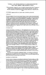
Abstract<br />
The use of alternative <strong>fuel</strong>s hold the promise of promoting energy<br />
diversity and reducing mo<strong>to</strong>r vehicle emissions. With the passage<br />
of the federal Clean Air Act Amendments of 1990, the National<br />
Energy Policy Act of 1992, and state initiatives such as from<br />
California, these <strong>fuel</strong>s will have a far reaching influence on the<br />
<strong>fuel</strong>s mo<strong>to</strong>r vehicle fleets operate on in the next century.<br />
Many of the emission benefits of alternative <strong>fuel</strong>s are dependent<br />
on the quality of the alternative <strong>fuel</strong> implementation, as well as<br />
the <strong>fuel</strong>s themselves. To prevent degradation of mo<strong>to</strong>r vehicle<br />
emissions, the Colorado Department of Health has implemented<br />
alternative <strong>fuel</strong> retrofit system certification procedures. These,<br />
as well as EPA and California certification standards will allow<br />
present vehicles <strong>to</strong> have acceptable emissions, as well as future<br />
vehicles <strong>to</strong> meet required low emission standards.<br />
Introduction<br />
Transportation <strong>fuel</strong>s have been at the heart of two major public<br />
policy issues facing the United States for the last several<br />
decades; <strong>pollution</strong> caused by mo<strong>to</strong>r vehicles, and the growing<br />
dependence on imported oil. Clean <strong>fuel</strong>s, such as alternative<br />
<strong>fuel</strong>s, are of increasing importance as a way <strong>to</strong> lower mo<strong>to</strong>r<br />
vehicle emissions. Diversification of transportation <strong>fuel</strong>s is<br />
equally important, and will lessen or mediate future supply<br />
disruptions or price hikes which were saw in the oil shocks of the<br />
1970s.<br />
In Colorado, alternative <strong>fuel</strong> use has been growing dramatically<br />
since the start of the 1990s. Today there are more than 5000<br />
vehicles capable of operating on alternative <strong>fuel</strong>s. This growth<br />
is posing significant challenges <strong>to</strong> the <strong>fuel</strong>s industry and fleet<br />
users. To support the expanding vehicle fleet, the <strong>fuel</strong>s industry<br />
has been actively expanding the alternative <strong>fuel</strong> infrastructure.<br />
In turn, fleet users are being challenged <strong>to</strong> integrate and<br />
maintain new types of vehicles and <strong>fuel</strong>s.<br />
Background<br />
Alternative <strong>fuel</strong> use in Colorado, and elsewhere, is been shaped<br />
largely by two significant pieces of federal legislation, the<br />
Clean Air Act Amendments of 1990 and the National Energy Policy<br />
Act of 1992. Developments in California are also effecting<br />
282
I<br />
I<br />
t<br />
alternative <strong>fuel</strong>ed mo<strong>to</strong>r vehicle use, as California "low emitting<br />
vehicle", "ultra low emitting vehicle" and "zero emitting vehicle"<br />
standards are driving the entire alternative <strong>fuel</strong>ed vehicle market<br />
The Clean Fleet Fuels Program<br />
The Clean Air Act Amendments of 1990 mandate the use of clean<br />
<strong>fuel</strong>s for fleets, mainly as part of the Clean Fleet Fuels Program.<br />
This program is scheduled <strong>to</strong> begin in 1998 for public and private<br />
fleet of ten or more vehicles which are centrally re<strong>fuel</strong>ed.<br />
The Clean Fleets Fuels Program affects fleets in 21 ozone and one<br />
carbon monoxide non-attainment areas with populations of 250,000<br />
or more based on the 1980 census. The program applies <strong>to</strong><br />
au<strong>to</strong>mobiles and light and heavy duty trucks up <strong>to</strong> 26,000 pounds<br />
gross vehicle weight.<br />
The Clean Fleet Fuels program is as the name suggests, a "clean"<br />
<strong>fuel</strong>s program. It is a program which stresses <strong>air</strong> quality, rather<br />
than type of <strong>fuel</strong>, so is a performance, rather than alternative<br />
<strong>fuel</strong>ed, based program. To participate, a <strong>fuel</strong>/vehicle combination<br />
must meet the same standard as the California low emitting vehicle<br />
standard.<br />
It is expected that alternative <strong>fuel</strong>s will have an advantage in<br />
meeting the specific emission requirements of this program, but<br />
reformulated gasoline8 and clean diesel <strong>fuel</strong>s may also<br />
participate. Any <strong>fuel</strong>, in combination with vehicle technology,<br />
which meets the standard is eligible for this program. This<br />
includes alternative <strong>fuel</strong>s such as natural gas, propane, methanol,<br />
ethanol, and electricity, as well as clean gaaolines and diesel<br />
<strong>fuel</strong>s. Some types of vehicles will be exempted <strong>to</strong> this program.<br />
They include emergency and law enforcement vehicles, and vehicles<br />
which are garaged at home.<br />
National Energy Policy Act of 1992<br />
A second federal program expected <strong>to</strong> <strong>fuel</strong> the market for<br />
alternative <strong>fuel</strong>s and <strong>fuel</strong>ed vehicles this decade and next, is the<br />
National Energy Policy Act of 1992. This act, unlike the Clean<br />
Fleet Fuels Program, is designed strictly <strong>to</strong> increase the use of<br />
alternative <strong>fuel</strong>s and <strong>fuel</strong>ed vehicles. It mandates that certain<br />
fleets purchase alternative <strong>fuel</strong>ed vehicles.<br />
The National Energy Policy starts in 1993 for the Federal fleet,<br />
and 1996 for State fleets and <strong>fuel</strong> provider fleets. Private and<br />
municipal fleets may have <strong>to</strong> participate also, as early as 1999,<br />
if the Secretary of Energy makes a determination that national<br />
alternative <strong>fuel</strong> usage goals require their inclusion <strong>to</strong> be met.<br />
The National Energy Policy act affects all metropolitan areas in<br />
the United States with a population of over 250,000 people at the<br />
time of the 1980 census. It covers eligible fleets of fifty or<br />
more vehicles, with at least 20 or more in any one area. It<br />
affects vehicles with weights up <strong>to</strong> 8500 GVW. In addition, the<br />
covered vehicles must be capable of being centrally re<strong>fuel</strong>ed.<br />
283
Unlike the Clean Fleet Fuels Program, this program is an energy<br />
diversity program, so is not standards driven but rather<br />
alternative <strong>fuel</strong> driven. Alternative <strong>fuel</strong>s which comply include,<br />
natural gas, propane, methanol, ethanol, and electricity.<br />
Exempted vehicles for this program include, emergency and law<br />
enforcement vehicles, and vehicles garaged at home. At the<br />
discretion of the Sectary of Energy, the exemption for law<br />
enforcement vehicles may be waived.<br />
State and Local Incentives<br />
Colorado, because of <strong>air</strong> quality issues, as well as economic<br />
developmental reasons has encouraged the use of alternative <strong>fuel</strong>s.<br />
In terms of <strong>air</strong> <strong>pollution</strong>, alternative <strong>fuel</strong>s do hold the promise<br />
of reducing vehicle emissions which contribute <strong>to</strong> Colorado's<br />
winter-time carbon monoxide and PM-IO problems, and year round<br />
visibility concerns.<br />
But showing promise does not necessarily lead <strong>to</strong> a solution. Mass<br />
emissions testing conducted by the Colorado Department of Health<br />
(CDH), has shown that not all alternative <strong>fuel</strong>ed vehicles are low<br />
emitting. As with traditional vehicles, good design and proper<br />
vehicle maintenance are needed <strong>to</strong> obtain and maintain appropriate<br />
vehicle emission levels. To assure that alternative <strong>fuel</strong>ed<br />
vehicles meet applicable emissions standards, the CDH regulates<br />
vehicle conversions through Air Quality Control Commission<br />
Regulation No. 14. Through this regulation, only CDH certified<br />
retrofit systems are allowed on vehicle conversions.<br />
To encourage the use of alternative <strong>fuel</strong>ed vehicles, the state,<br />
and local municipalities, have adopted a number of incentive<br />
programs. One of the first programs established was a state fleet<br />
program which requires the state fleet manager <strong>to</strong> purchase or<br />
convert a number of vehicles <strong>to</strong> alternative <strong>fuel</strong>s each year.<br />
Beginning in fiscal year 1991, the goal was 10% of all new vehicle<br />
purchases. This has been'increased <strong>to</strong> 40% for the fiscal 1994<br />
year.<br />
The city of Denver has adopted a more pervasive ordinance, No.<br />
330, administered by the City of Denver Health and Hospitals,<br />
requiring 10% of all fleet vehicles <strong>to</strong> be alternatively <strong>fuel</strong>ed for<br />
fleets of 30 of more vehicles. Diesel powered vehicles are<br />
excepted from conversion requirements, but are counted as part of<br />
that 30 or more vehicles.<br />
Governor's Alternative Fuels Task Force<br />
To encourage the use of alternative <strong>fuel</strong>s, Colorado's governor,<br />
Governor Romer, established a Governor's Alternative Fuels Task<br />
Force. It was charged with the task of investigating ways of<br />
furthering the use of alternative <strong>fuel</strong>s. This Task Force,<br />
composed of local state, county, and municipal officials, as well<br />
as citizens, met for over a year in determining the direction<br />
Colorado should take in meeting both clean <strong>air</strong> goals and economic<br />
development.<br />
284<br />
A
I<br />
1<br />
J<br />
k<br />
The principle recommendation of the Task Force was that Colorado<br />
implement a Clean Fleet Fuels Program as required by the Clean Air<br />
Act Amendments of 1990. Such a program should be implemented as<br />
soon as possible before the 1998 deadline.<br />
The task force also<br />
recommended an incentive program be developed <strong>to</strong> promote <strong>fuel</strong>s<br />
such as CNG and propane which could reduce carbon monoxide<br />
emissions from appropriate vehicles. As a gas producing State,<br />
the use of <strong>fuel</strong>s such as CNG and propane were also favored as a<br />
way of meet both clean <strong>air</strong> objectives, as well as economic<br />
development goals.<br />
The recommendations of the Task force were given statu<strong>to</strong>ry<br />
authority through the passage of House Bill 1305.<br />
House Bill 1305 authorized the Colorado Clean Vehicle Fleet<br />
Program, which will conform with the federal Clean Fleet Fuels<br />
Program mandated by Clean Air Act Title I, Part D and Title 11,<br />
Part C , 1990.<br />
The Colorado program will affect fleets with 10 or more vehicles<br />
in the Denver-Boulder CO non-attainment area. Colorado is the<br />
only state participating in the Clean Fleet Fuels Program Strictly<br />
due <strong>to</strong> having a carbon monoxide non attainment area. Other states<br />
which have areas required <strong>to</strong> implement this program, and are in<br />
nonattainment for carbon monoxide, are also nonattainment for<br />
ozone.<br />
By House Bill 1305, the Colorado Air Quality Control Commission<br />
was given the authority <strong>to</strong> promulgate rules and regulations for<br />
the implementation of this program. At the present time, the AQCC<br />
is preparing a regulation which will implement the program.<br />
House Bill'1305 also authorizes the establishment of a mechanic<br />
certification program for vehicle conversions, and authorizes the<br />
establishment, but does not fund, an alternative <strong>fuel</strong>s rebate<br />
program authorized <strong>to</strong> rebate up <strong>to</strong> half the cost of a vehicle<br />
conversion, or the alternative <strong>fuel</strong>ed vehicle premium on new<br />
vehicles. Such vehicles must demonstrate that reductions in<br />
carbon monoxide emissions, as well as for fine particulate matter,<br />
visibility pollutants will be achieved.<br />
Other Activities<br />
As in other states, there is also much activity being conducted<br />
through federally funded pilot programs, such as the Regional<br />
Transportation District operation of five large over the road<br />
methanol <strong>fuel</strong>ed transit buses, as well as large and smaller CNG<br />
powered buses. The U.S. Government Accounting Office is also in<br />
the process of obtaining a fleet of methanol flexible <strong>fuel</strong>ed<br />
au<strong>to</strong>mobiles. Coors brewing is operating an ethanol powered semi-<br />
truck trac<strong>to</strong>r and a fleet of propane powered vans. Many other<br />
private and governmental fleets are also now operating CNG or<br />
propane powered vehicles.<br />
The National Renewable Energy Lab is in the process of developing<br />
ways of lowering ethanol production costs. The Colorado School of<br />
Mines has established a heavy duty emissions labora<strong>to</strong>ry, and<br />
colorado State University has established a light duty emissions<br />
labora<strong>to</strong>ry which are both measuring mo<strong>to</strong>r vehicle emissions from<br />
alternative <strong>fuel</strong>ed vehicles.<br />
285
Conclusion<br />
Presently almost all transportation <strong>fuel</strong>s used are derived from<br />
oil. Increaeingly that oil is imported. In 1990 it is estimated<br />
that close <strong>to</strong> half of all oil consumed in the United States was<br />
imported. With consumption increasing and production decreasing,<br />
it is expected that by the year 2010, approximately 70% of all oil<br />
consumed in the United States will be imported, if the measures in<br />
the National Policy Act are not implemented.<br />
New federal clean <strong>fuel</strong> requirement8 will pose a significant<br />
challenge <strong>to</strong> states in the future. New alternative <strong>fuel</strong><br />
infrastructures will have <strong>to</strong> be created. New mo<strong>to</strong>r vehicle<br />
designs will also be needed <strong>to</strong> utilize those <strong>fuel</strong>s for maximum <strong>air</strong><br />
quality and vehicle performance benefit. The potential is there<br />
<strong>to</strong> take advantage of the different characteristics of the new<br />
clean <strong>fuel</strong>s <strong>to</strong> lower vehicle emissions as well as develop secure<br />
supplies of North American produced <strong>fuel</strong>.<br />
286
I<br />
OXYGENATED GASOLINE-THE CALIFORNIA EXPERIENCE<br />
Dan C. Sirnemth and Jose Gomtx<br />
California Air Resources Board<br />
2020 L Street<br />
P.O. Box 2815<br />
Sacramen<strong>to</strong>, CA 95812<br />
KEYW'ORDS: Oxygenated Gasoline. California wintertime oxygenates regulations, gasoline oxygen content<br />
ABSTRACT<br />
The Air Resources Board (ARB) adopted regulations in December 1991, which require that gasoline contain 1.8<br />
<strong>to</strong> 2.2 weight percent oxygen during specified months. The regulations were adopted in response <strong>to</strong> the Federal<br />
Clan Air Act Amendments of 1990. California's wintertime oxygenates program was implemented November<br />
1, 1992. The use of <strong>oxygenated</strong> gasoline reduced ambient carbon monoxide concentrations by six <strong>to</strong> ten percent<br />
during the first implementation season. The wintertime oxygenates regulations sunset February 29, 1996. At<br />
that time, the wintertime oxygen content requirement becomes part of the Phase 2 reformulated gasoline<br />
regulations.<br />
INTRODUCTION<br />
This paper summariles the California wintertime oxygenates regulations and discusses California's experience in<br />
implementing these regulations.<br />
In response <strong>to</strong> the requirements of the federal Clean Air Act Amendments of 1990 (Act), the ARB adopted<br />
regulations in December 1991, which require that gasoline contain 1.8 <strong>to</strong> 2.2 weight percent oxygen during<br />
specified months. These regulations were implemented on November 1, 1992. Because California's regulations<br />
differ from the federal requirements, the ARB requested a partial waiver under section 21 l(m)(3) of the Act.<br />
The U.S. Environmental Protection Agency (U.S.EPA) is currently reviewing ARB'S request for a waiver.<br />
Based on our review of the program's first implementation season, the Board approved minor modifications <strong>to</strong><br />
the regulations on September 9, 1993, which are intended lo provide additional flexibility <strong>to</strong> those required <strong>to</strong><br />
comply with the regulations. while not compromising the overall effectiveness of the program.<br />
BACKGROUND<br />
The Federal Requirements<br />
The Act requires states with carbon monoxide (CO) nonattainment areas lo implement <strong>oxygenated</strong> gasoline<br />
programs in these areas. In most cases, the states' program must require that gasoline sold in the<br />
nonattainment areas have an oxygen content of at least 2.7 weight percent, during the specified months. The<br />
states are required <strong>to</strong> submit their <strong>oxygenated</strong> gasoline regulations as a revision <strong>to</strong> the State Implementation Plan<br />
(SIP). The U.S.EPA identified eight areas in California in which an <strong>oxygenated</strong> gasoline program is required,<br />
including: the Chic0 Metropolitan Statistical Area (MSA), the Sacramen<strong>to</strong> MSA, the SM Diego MSA, the<br />
Modes<strong>to</strong> MSA, the Fresno MSA, the S<strong>to</strong>ck<strong>to</strong>n MSA, the San Francisco-Oakland-San Jose Consolidated<br />
Metropolilan Statistical Area (CMSA). and the Los Angeles-Anaheim-Riverside CMSA. The EPA also<br />
specified the control period applicable in each of the affected areas'. The control periods are listed in Table 1.<br />
ARB's Actions <strong>to</strong> Comply with the Act<br />
In response <strong>to</strong> the requirements of Section 211(m), the ARB promulgated <strong>oxygenated</strong> gasoline regulations<br />
following a hearing on December 12, 1991. The regulations were submitted as a revision <strong>to</strong> the SIP in Oc<strong>to</strong>ber<br />
1992. The wintertime oxygenates regulations sunset February 29, 1996, after which the year-round oxygen<br />
content requirements in the ARB'S Phase 2 reformulated gasoline regulalions will go in<strong>to</strong> effect. Because over<br />
70 percent of the gasoline used statewide is consumed in the U.S.EPAdesignated areas, the Board made the<br />
wintertime oxygenates regulations applicable statewide. Additionally, the Board concluded that a statewide<br />
program simplifies enforcement and maximizes the CO emission reductions achieved in the nonattainment areas.<br />
In setting the standards, the Board determined that while requiring the 2.7 weight percent oxygen content<br />
mandated by the Act would result in greater CO reductions it would also result in increased emissions of NO,.<br />
An increase in NO, emissions would interfere with efforts <strong>to</strong> attain the ambient <strong>air</strong> quality standards for<br />
particulate matter (PM,J, nitrogen dioxide (NO3 and ozone. Therefore, the Board established a minimum and<br />
maximum oxygen content requirement at 1.8 and 2.2 weight percent. respectively.<br />
The Board has requested that the U.S.EPA partially waive the minimum oxygen content requirement of 2.7<br />
weight percent specified in the Act. Section 211(m)(3)(A) of the Act directs the U.S.EPA <strong>to</strong> waive the<br />
requirement for MY area where the state demonstrates that the use of <strong>oxygenated</strong> gasoline would prevent or<br />
interfere with the area's, attainment of an ambient <strong>air</strong> quality standard for any pollutant other than CO.<br />
IhlPACT OF OXYGENATED GASOLINE ON MOTOR VEHICLE EMISSIONS<br />
Adding oxygen <strong>to</strong> gasoline affects the properties of gasoline in both performance and emissions. Generally, the<br />
oxygenates used <strong>to</strong>day are ethanol and methyl tertiary butyl ether (MTBE). Over the past several years. there<br />
have been a number of test program conducted <strong>to</strong> evaluate the impact of oxygen content on emissions. In the<br />
process of developing the wintertime oxygenates regulations, we evaluated all of the studies available <strong>to</strong> us at<br />
287
the time and concluded that oxygen content in gasoline greater than 2.2 weight percent would increase. NO,<br />
emissions from mo<strong>to</strong>r vehicles23". In general. NO, emissions increase as oxygen content increases.<br />
Since the adoption of the wintertime oxygenates regulations and the Phase 2 reformulated gasoline regulations.<br />
we have heen working <strong>to</strong> develop a predictive d e l <strong>to</strong> estimate emissions from alternative gasoline<br />
formulations that might be used in the vehicle fleet. As pari of our waiver request lo U.S.EPA, we used a draft<br />
version of the predictive model <strong>to</strong> evaluate the emissions characteristics of the most likely gasoline formulation<br />
that would be produced under the federal program'. This gasoline formualtion was developd as part Of an<br />
analysis conducted by Turner Mason and Company for the Western Stales Petroleum Association. It should be<br />
noted that variations in the gasoline kormulations actually produced will influence the actual impact on NO,<br />
emissions. Figure 1 shows the estimated impact on NO, emissions for the different vehicle technology groups.<br />
RATIONAL FOR LIMITING THE OXYGEN CONTENT OF GASOLINE<br />
Emissions Inven<strong>to</strong>ry<br />
Mo<strong>to</strong>r vehicle emissions are a major source of pollutant emissions, iacluding CO. hydrocarbons (HC), and NO..<br />
HC and NO, are precursors <strong>to</strong> owne and PM,,. Figure 2 shows that in 1987 emissions from on-road gasoline<br />
mo<strong>to</strong>r vehicles constituted about 57 percent of the <strong>to</strong>tal CO inven<strong>to</strong>ry, 35 percent of the VOC inven<strong>to</strong>ry. and 38<br />
percent of the NO, inven<strong>to</strong>ry. Gasoline vehicles accounted for about 36 percent of the PM,, precursors.<br />
Air Quality in EPA-designated Areas<br />
Both the owne and PM,, standards are exceeded in all EPA-designated areas during some time in the control<br />
period. Figure 3 shows the average number of days the state ozone standard was exceeded during the period of<br />
1987 through 1990 for five <strong>air</strong> basins (which contain all of the U.S.EPA designated areas). Figure 4 shows the<br />
average percent of PM,, observations exceeding the state slandard. Because violations of the standards for CO,<br />
NO2, owne, and PM,, can occur simultaneously, it is critical that ths efforts lo reduce CO emissions don't<br />
increase emissions of the other pollutants.<br />
As ~oted earlier, use of gasoline with oxygen content greater than 2.2 weight percent would result in larger CO<br />
reductions of CO emissions, hut it would also increase NO. emissions. Thus, it is critical <strong>to</strong> balance the need<br />
for CO reductions and the need <strong>to</strong> avoid NO. increases. California's <strong>oxygenated</strong> gasoline regulations were<br />
designed <strong>to</strong> balance these competing effects.<br />
ARB'S EXPERIENCE IMPLEMENTING THE OXYGENATED GASOLINE PROGRAM<br />
Implementation hues<br />
During the first implementation period of the wintertime <strong>oxygenated</strong> gasoline program, sfaff became aware of<br />
various concerns regarding the application of the wintertime oxygenates regulations. After evaluation of the<br />
program, staff proposed several minor modifications <strong>to</strong> the regulations which were adopted by the Board on<br />
September 9, 1993'. The modifications include changing the control period applicable in the San Luis Obispo<br />
County, allowing the distribution of gasoline containing greater than 2.2 weight percent oxygen during the<br />
transition period, providing a one pound per square inch Reid vapor pressure exemption for ethanol blended<br />
gasoline produced during the calibration of blending equipment, and providing an exemption for small gasoline<br />
retailers that obtain their gasoline from areas outside California, if they meet specified conditions. These<br />
changes are intended <strong>to</strong> provide industry with additional flexibility in complying with the regulations, while<br />
maintaining the effectiveness of the regulations.<br />
Air Quality Improvements During the 1992/93 Winter<br />
Results of an analysis of CO, NOx, and HC ambient <strong>air</strong> quality data collected at nine moni<strong>to</strong>ring stations during<br />
the November 15. 1992 through Januarry 31, 1993 period indicates that concentrations of CO were significantly<br />
lower than past winters'. Although the 1992193 winter had very favorable meteorology. we believe some of the<br />
reduction in CO concentrations are due <strong>to</strong> the use of <strong>oxygenated</strong> gasoline.<br />
A linear regression analysis was done on the available data for the winter periods of 1985/86 through 1991/92<br />
<strong>to</strong> characterize trends for the three periods 6 lo 9 am., 6 <strong>to</strong> 9 p.rn., and daily mean concentrations. The<br />
regression equations were used lo compute the expected concentralions for CO. NO,, and HC for the 1992/93<br />
winter. The actual values for 1992193 winter were divided by the expected values derived from the regression<br />
analysis.<br />
The ratio of the 1992193 actual concentrations <strong>to</strong> the expected concentralions were 72 percent for CO and 78<br />
percent for NOx, respectively. The ratios of the NO, concentrations were assumed lo characterized the<br />
atmospheric dispersion during the winter 1992/93. Thus, the difference between the CO ratios and the NO,<br />
ratios was attributed <strong>to</strong> the use of the <strong>oxygenated</strong> gasoline. The analysis indicates that the use of Oxygenated<br />
gasoline accounted for about a six <strong>to</strong> 10 percent reduction in CO concentrations. Figure 5 shows a summary of<br />
'<br />
the ratios of actual <strong>to</strong> expected the concentrations of CO and NO.<br />
CONCLUSIONS<br />
California has successfully implemented its <strong>oxygenated</strong> gasoline regulations applicable in the winter months<br />
which has resulted in significant reductions of carbon monoxide emissions from mo<strong>to</strong>r vehicles. Although the<br />
regulations require a lower oxygen content than the minimum 2.7 weight percent specified in the Act, the<br />
regulations have been effective in reducing CO emissions. Minor modifications were made in September 1993<br />
<strong>to</strong> address concerns raised during the first implementation season.<br />
288<br />
i
California’s wintertime oxygenates regulations will help bring all CO nonattainment areas in<strong>to</strong> compliance with<br />
the co ambient <strong>air</strong> quality standards by the statu<strong>to</strong>rily require deadlines. Additionally, the Phase 2<br />
reformulated gasoline regulations which will become effective in March of 1996, will result in an additional CO<br />
reduction of about five percent.<br />
REFERENCES<br />
1. US. Environmental Protection Agency, Supplemenrnl Norice of Proposed Guidnnce on Esroblishmenr of<br />
Conrrol periods Under Secrion Zll(nrJ of rhe Cleon Air AR ar Amended, 57, FR 4408, February 5. 1992.<br />
2. Air Resources Board, Cnlifornin Phnse 2 Reformulored Gnroline Specificnrions. Volunre 2 Proposed<br />
Reeulnrion for Cnlifornin Winrerrime Oxypennres Proprom, Oc<strong>to</strong>ber 4, 1991.<br />
3. Air Resources Board, Cnlifornin Winrenime Oxveerrnres Proeram. Technicnl Sumon Documenr. Reouesl for<br />
fl Waiver of rhe Minimum Oxyeen Conrenr Reouiremenrs for Winrenime Gnsoline. Pursuanr Io Federal Clean Air<br />
An Senion 2JllmJ(3JfAl, Oc<strong>to</strong>ber 1992.<br />
4. Air Resources Board, Cnlifornin Winrenime Oxvpennres Proernm. Technicnl SunDon Documenr. Reouesr for<br />
fl wniver of the Minimum Ompen Conrenr Renuiremenrs for Winrertime Gasoline. Pursunnr lo Federnl Clem Air<br />
An Senion 211-, Supplemental SubmitLal <strong>to</strong> U.S. EPA Docket No. A-93-13. June 17, 1993.<br />
5. Air Resources Board, Proposed Amendmenrs io Reeulorions Reeordine the Oxypen Conrenr of Garolirre. and<br />
Reanrdirw Eremprions from Mo<strong>to</strong>r Vehicle Fuels Reouiremenrs for Fuels Used in Test Proernms, July 23, 1993.<br />
6. Dolislager, LMn J., Air Resources Board, Did rhe Winrenime Oxveennred Fuels Proprnm Reduce Cnrbon<br />
Monoxide Concenrrflrion in Cnlifornin?. Presented at the Tenth International Symposium on Alcohol Fuels,<br />
November 7-10, 1993, Colorado Springs, CO.<br />
289
-<br />
EPA-Designated Areas Control Period<br />
Cbim MSA* I Oc<strong>to</strong>ber 1 I Januaw 31<br />
I Sacramen<strong>to</strong> MSA<br />
Oc<strong>to</strong>ber 1 January 31<br />
San Diego MSA<br />
November 1 February 29<br />
Modes<strong>to</strong> MSA<br />
Oc<strong>to</strong>ber 1 January 31<br />
Fresno MSA<br />
Oc<strong>to</strong>ber 1 January 31<br />
S<strong>to</strong>ck<strong>to</strong>n MSA<br />
Oc<strong>to</strong>ber 1 Januaj 31<br />
San Francisco-Oakland-San Jose CMSA** Oc<strong>to</strong>ber 1 January 31<br />
Los Angeles-Anaheim-Riverside CMSA Oc<strong>to</strong>ber 1 February 29<br />
Figure 1<br />
Results of ARB'S Predictive Model for<br />
Gasoline Most Likely lo be Produced<br />
Under 2.7 wt. % Program<br />
_. -<br />
. . . - . . . . .<br />
Tech 1 Tech 2 Tech 3 Tech 4<br />
Vehicle Technology Group<br />
Figure 2<br />
1987 Slatewlde Ernlsrlons Inven<strong>to</strong>ry<br />
Carban Monoxide voc<br />
290
20<br />
0.74 t<br />
Fiaure 3<br />
Avg. Number of Days Exceeding<br />
the Ozone State Standard<br />
(1987 -1990 Data)<br />
JFOND JFOND JFOND JFOND JFONO<br />
San Francis0 South Coast San Dicgo Sae<strong>to</strong> San Josquin<br />
Air Basin<br />
Figure 4<br />
Avg. Percent of PMIO Observations<br />
Exceeding the 24-hr State Standard<br />
(1987- 1990 Data)<br />
SanFranciwo South Coast SanDiego Sac<strong>to</strong> San Joaquin<br />
.<br />
Air Basin<br />
Figure 5<br />
Rallos of Actual <strong>to</strong><br />
Expected Concentrallons<br />
(wi"t.r SM3)<br />
__ .<br />
.______._______<br />
0.7 ' 6-9 AM 6-9 PM Daily Mean<br />
Time Perlod<br />
i& CO ratios NOx ratios<br />
291<br />
I<br />
1<br />
I
Abstract<br />
ENVIRONHENTAL AND ECONOMIC IMPLICATIONS<br />
OF OXYGENATED GASOLINE USE IN COLORADO:<br />
COLORADO'S OXYGENATED GASOLINE PROGRAM<br />
Kim 6. Livo<br />
Dr. Jerry Gallagher<br />
Air Pollution Control Division<br />
Colorado Department of Health<br />
4300 Cherry Creek Drive South<br />
Denver, Colorado 80222<br />
Starting in the winter of 1987-1988, Colorado instituted an<br />
<strong>oxygenated</strong> gasoline program <strong>to</strong> control winter-time carbon monoxide<br />
emissions from mo<strong>to</strong>r vehicles. As a result of this and other <strong>air</strong><br />
quality programs, as well as fleet turn over, the number of days<br />
exceeding the federal carbon monoxide standard has been reduce<br />
from 32 days in 1986 <strong>to</strong> 5 days in 1992.<br />
The Colorado Department of Health estimates that for the winter of<br />
1992-1993, carbon monoxide emissions from mo<strong>to</strong>r vehicles were<br />
reduced by 25% on a fleet wide basis. This reduction is credited<br />
with preventing a possible four additional high <strong>pollution</strong> days<br />
from occurring. The use of these gasolines increased the cost of<br />
gasoline in the Denver area by 3.5 cents per gallon.<br />
Introduction<br />
The Front Range area of Colorado is subject <strong>to</strong> numerous carbon<br />
monoxide (CO) high <strong>pollution</strong> episodes each winter. These are<br />
produced by the interaction of cold temperatures, temperature<br />
inversions, and carbon monoxide emissions from gasoline powered<br />
au<strong>to</strong>mobiles and trucks, as well as from residential wood burning<br />
and other sources. Of the <strong>to</strong>tal CO emissions, mobile sources<br />
contribute approximately 85%.<br />
Elevated carbon monoxide concentrations occur on calm winter days,<br />
when temperature inversions develop which inhibit the dispersion<br />
of carbon monoxide produced from mo<strong>to</strong>r vehicle traffic and<br />
residential wood burning. Exceedances of the federal eight hour<br />
CO standard may result, especially in low laying, high traffic<br />
volume areas, such as down<strong>to</strong>wn Denver.<br />
As one of several <strong>strategies</strong> aimed at reducing mo<strong>to</strong>r vehicle CO<br />
emittions, the Colorado Department of Health (CDH) instituted an<br />
<strong>oxygenated</strong> gasoline program beginning in the winter of 1987-1988.<br />
Implementation of this program resulted from a comprehensive<br />
vehicle mass emissions test program conducted by the CDH in the<br />
1980s.<br />
Vehicle Mass Emissions Testing<br />
Beginning with vehicle mass emissions testing in the late 1970s by<br />
the U.S. EPA, and soon after, by the Colorado Department of<br />
Health, it was noted that gasolines blended with alcohols, such as<br />
292<br />
I'
i<br />
I<br />
I<br />
I'<br />
i<br />
ethanol and methanol, produced lower carbon monoxide emissions<br />
than non-blended gasolines (1,2). Later testing involving methyl<br />
tert-butyl ether (MTBE) blends produced similar results (3).<br />
The test method used in this program is a mass-emissions test<br />
called the Federal Test Procedure (FTP). It is used by the U.S.<br />
EPA <strong>to</strong> certify emissions for new model light duty cars and trucks.<br />
In this test, a vehicle is placed on a dynamometer and is driven<br />
over a simulated driving cycle lasting 1372 seconds. Vehicle<br />
emissions are collected during this period, and the mass of these<br />
emissions are determined.<br />
The driving cycle involves both cold<br />
and hot vehicle starts, accelerations, decelerations, and steady<br />
cruise conditions, designed <strong>to</strong> simulate a typical urban commute.<br />
Analyzing mass emissions results from these tests indicated that<br />
<strong>fuel</strong> oxygen content, rather than the particular oxygenate, was the<br />
most important parameter in producing carbon monoxide changes. In<br />
determining this effect, the CDH examined both linear and<br />
logarithmic relationships <strong>to</strong> correlate the mass emissions database<br />
(4). For the logarithmic models, both positive as well as<br />
negative curves could be fitted <strong>to</strong> the data, depending on the<br />
individual study analyzed. Because of the differences in<br />
curvatures, as well as because the linear model fit equally as<br />
well as the logarithmic models, a linear model has been adopted in<br />
describing the CO effect of using <strong>oxygenated</strong> gasolines.<br />
Table 1<br />
describes the CDH carbon monoxide FTP mass emissions results using<br />
the linear model, averaged for oxygen content, and differentiated<br />
by vehicle emissions control technology class.<br />
The U.S. EPA and other organizations have also conducted mass<br />
emission test programs which have corroborated and expanded upon<br />
the CDH mans emissions testing. In the latest study, the Au<strong>to</strong>/Oil<br />
Air Quality Improvement Research Program, <strong>fuel</strong> composition<br />
parameters, including oxygen content, have been varied <strong>to</strong> study<br />
emissions effects (5). Again, directionally, increasing oxygen<br />
content was found <strong>to</strong> reduce carbon monoxide emissions.<br />
CO Vehicle Emission Reductions<br />
In analyzing the CO vehicle emission reduction of <strong>oxygenated</strong><br />
gasolines, the CDH relies on the U.S. EPA MOBILE vehicle emissions<br />
model. Employing this computer model, vehicle emissions from an<br />
area's mo<strong>to</strong>r vehicle fleet can be averaged and estimated. This<br />
model takes the CO emission reductions seen in the FTP mass<br />
emissions testing, and applies it across the entire mo<strong>to</strong>r vehicle<br />
fleet, and under different driving conditions. Inputs <strong>to</strong> the<br />
model include: vehicle age and distribution, speed, road type,<br />
time of day, and area type.<br />
Utilizing the present MOBILE Sa emissions model, the CDH estimates<br />
that in the winter of 1992-1993, carbon monoxide exhaust emissions<br />
from mo<strong>to</strong>r vehicles, in the Front Range area, were reduced by<br />
26.6% in Oc<strong>to</strong>ber and November, and by 24.9% in January and<br />
February (6). Reductions in ambient CO concentrations are less,<br />
since mobile sources are not the sole eource of CO emissions, and<br />
concentrations are dependent on the rates of production and<br />
d ispers ion.<br />
293
concrlbutirig <strong>to</strong> the effectiveness of the 1992-1993 program was the<br />
increased percentage of ethanol blended gasoline sold along the<br />
Front Range area. Ethanol blends made up 45% of the <strong>to</strong>tal<br />
gasoline sales of this winter, compared <strong>to</strong> 20% the winter before.<br />
When blended at the 108 vol. level, ethanol blends have a higher<br />
oxygen content than 15% MTBE blends (3.5% VS. 2.7% ut.). A higher<br />
oxygen content produces a greater average CO reduction. 15% vol.<br />
MTBE blends constituted the balance of the <strong>oxygenated</strong> gasoline<br />
sold.<br />
During the winter of 1992-1993, the average oxygen content of the<br />
Front Range gasoline pool'was 3.0% percent in November and<br />
December, dropping <strong>to</strong> 2.8% for January and February, when a new<br />
I.R.S. ruling <strong>to</strong>ok effect, permitted the blending of ethanol at a<br />
reduced level (7.8% vs. 10% vol.).<br />
Air Quality<br />
In terms of ambient <strong>air</strong> quality, there were five exceedances of<br />
the 9ppm eight-hour average national ambient <strong>air</strong> quality standard<br />
(NAAQS) for CO in the winter of 1992-1993. An additional four<br />
possible exceedances were prevented because of the use of<br />
<strong>oxygenated</strong> gasolines (6). Figure 1 documents the daily 8-hour<br />
maximum reading for the winter of 1992-1993. The lower clear bar<br />
represents moni<strong>to</strong>red values. The solid dark bars represent<br />
estimated concentrations, if <strong>oxygenated</strong> gasolines were not used.<br />
For the calendar year 1992, there were five days exceeding the<br />
NAAQS &hour average CO standard, a declined from 32 days in the<br />
calendar year of 1986. The continuing reduction in CO exceedances<br />
as shown in Figure 2, is due <strong>to</strong> a continuing decline in CO<br />
emissions due <strong>to</strong> fleet turn over, the use of <strong>oxygenated</strong> gasolines,<br />
vehicle inspection and maintenance programs, and no woodburning on<br />
high <strong>pollution</strong> days, as well as favorable weather conditions.<br />
costs<br />
The Colorado Department of Health analyzed the costs associated<br />
with the 1992-1993 <strong>oxygenated</strong> gasoline program. The costs of base<br />
gasoline, Oxygenates, transportation costs, as well as octane and<br />
butane credit savings were examined <strong>to</strong> determine <strong>oxygenated</strong><br />
gasoline costs. These were then compared <strong>to</strong> the differential<br />
costs observed between <strong>oxygenated</strong> and non-<strong>oxygenated</strong> gasolines<br />
Denver RACK prices received from the Oil Price Information<br />
Service. Retail prices were also observed.<br />
For the winter of 1992-1993, the average cost of gasoline<br />
increased by three and a half cents per gallon because of the<br />
Oxygenated Gasoline Program (6), a similar amount as for previous<br />
season's program. This cost represents increased refiner and<br />
blender costs due <strong>to</strong> oxygenate blending and does not take in<strong>to</strong><br />
account any changes in vehicle <strong>fuel</strong> economy.<br />
While the average cost associated with blending oxygenates<br />
remained the same as the previous winter, the cost of gasoline<br />
blended with ethanol rose slightly. Average program costs<br />
remained similar <strong>to</strong> the 1991-1992 season however, because the<br />
294<br />
I
market share for ethanol blends increased, and ethanol blended<br />
gasoline costs remained below MTBE blended gasoline costs (2.75<br />
centsfgal. VB 3.75 centsfgal.).<br />
supplies<br />
This year over 360 million gallons of <strong>oxygenated</strong> gasoline were<br />
sold along the Front Range during the <strong>oxygenated</strong> gasoline program<br />
period (November 1, 1992 through February 28, 1993). Statewide,<br />
over 500 million gallons of gasoline (much of it <strong>oxygenated</strong>) was<br />
sold during this period.<br />
Fuel Economy<br />
Oxygenated gasolines have a small affect on <strong>fuel</strong> economy at high<br />
altitude. CDH <strong>fuel</strong> economy testing conducted during vehicle ma88<br />
emission FTP testing, has 'shown on average, <strong>fuel</strong> economy<br />
reductions of up <strong>to</strong> 1.5% for some vehicle classes <strong>to</strong> slight<br />
increases of less than 1.0% for other mo<strong>to</strong>r vehicle classes.<br />
Oxygenated gasolines lean the <strong>air</strong> <strong>to</strong> <strong>fuel</strong> ratio of a vehicle,<br />
increasing the engine's efficiency and in some older vehicles<br />
slightly improving <strong>fuel</strong> economy. Oxygenated gasolines have a<br />
slightly lower heating value though, which may decrease <strong>fuel</strong><br />
economy in some vehicles, especially vehicles equipped with the<br />
latest oxygen sensors and feedback <strong>fuel</strong> injection. Altitude and<br />
the partial pressure at Denver (5280 feet) may also lessen <strong>fuel</strong><br />
economy impacts of <strong>oxygenated</strong> gasolines. Table (2) gives CDH high<br />
altitude <strong>fuel</strong> economy test results for three types of emission<br />
control technologies, using 11% and 15% HTBE blends, and 10%<br />
ethanol blends.<br />
Conclusions<br />
Based on mass emissions testing, using the Federal Test Procedure,<br />
<strong>oxygenated</strong> gasoline have been demonstrated <strong>to</strong> decrease carbon<br />
monoxide emissions from gasoline powered mo<strong>to</strong>r vehicles. This<br />
decrease is related <strong>to</strong> oxygen content, and varies according <strong>to</strong><br />
vehicle emission control technology class and vehicle operating<br />
modes. For the FTP, based on a linear oxygen effect, <strong>oxygenated</strong><br />
gasolines decrease exhaust CO emissions by 4.83% <strong>to</strong> 6.45% for each<br />
one percent oxygen content, by weight, the gasoline contains.<br />
Using the U.S. EPA MOBILE Sa mo<strong>to</strong>r vehicle emissions model, the<br />
CDH estimates that carbon monoxide emissions were reduced by 24.9<br />
<strong>to</strong> 26.6% in the winter of 1992-1993. As a result of this and<br />
other <strong>air</strong> quality programs, as well as fleet turn over, the number<br />
of days exceeding the federal carbon monoxide standard has been<br />
reduce from 30 days in 1986 <strong>to</strong> 5 days in 1992. The use of these<br />
gasolines increased the cost of gasoline in the Denver area by 3.5<br />
cents per gallon.<br />
295
REFERENCES<br />
1.<br />
2.<br />
3.<br />
4.<br />
5.<br />
6.<br />
Richardson, David, "Exhaust Emissions and Fuel Economy from<br />
Au<strong>to</strong>mobiles using Alcohol/Gasoline Blends under High<br />
Altitude Conditions", U.S. EPA, Office of Air, Noise, and<br />
Radiation, Oct. 1978.<br />
Hollman, Ted, William Miron, "Effects of Ethanol-Blended<br />
Fuel on Mo<strong>to</strong>r Vehicles at High Altitude", Colorado<br />
Department of Health, Air Pollution Control Division, Mobile<br />
Sources Program, Sept. 1983.<br />
Ragazzi, Ron, "The Effects of Two Different Oxygenated Fuels<br />
on Exhaust Emissions at High Altitude", Colorado Department<br />
of Health, Air Pollution Control Division, Mobile Sources<br />
Program, Jan. 1987.<br />
Nelson, Ken, "The Effects of Fuel Oxygen on CO Emissions at<br />
High Altitudes",Colorado Department of Health, Air Pollution<br />
Control Division, Mobile Sources Program, May 1990.<br />
Au<strong>to</strong>/Oil Air Oualitv Imurovement Research Proaram (SP-920L,<br />
Society of Au<strong>to</strong>motive Engineers, Feb. 1992.<br />
Livo, Kim, Wi'lliam Miron, "1993 Oxygenated Gasoline Program,<br />
Air Pollution Control Division Report <strong>to</strong> the Colorado Air<br />
Quality Control Commission", Colorado Department of Health,<br />
Air Pollution Control Division, Mobile Sources Program,<br />
April 15, 1993.<br />
AVKRhol PEPCENT URBON WNOXIDE RBDUCTION<br />
ar mmcw EMISSION CWTROL rzcHNoLar cuss<br />
AND OWDEN CONCBNTRITION<br />
296
I<br />
f<br />
I'<br />
( PPm 1<br />
Figure 1<br />
Winter-time CO Concentrations<br />
With and Without Oxygenated Gasoline<br />
f8-HR DAILY MAX)<br />
-. - _. - - . . - -<br />
I<br />
18<br />
13.5 ........... ._ . ___ .-<br />
Standard II t I<br />
Number of Violation Days<br />
35<br />
30<br />
25<br />
20<br />
15<br />
10<br />
5<br />
Winter 1992 - 1993<br />
Moni<strong>to</strong>red and Projected CO Conc 1<br />
O w 02 Gasoline Wwlo 02 Gasoline [<br />
Figure 2<br />
Colorado CO Exceedances<br />
.-<br />
....................<br />
0<br />
1985 1986 1987 1988 1989 1990 1991 1992<br />
Calendar Years<br />
297
s<br />
TABLE (21<br />
FUEL ECONOMY EFFECTS<br />
CDH FTP Ileanured<br />
VEHICLE lu.1 Kco- Change<br />
TECHNO-I<br />
111 MTBB 151 MTB6 108 ethanol<br />
Y I<br />
non-c.ta1y.t tO.BZ8 t0.218 +0.118<br />
c.ta1y.t +0.84\ tO.188 t0.338<br />
298
k<br />
WHY ARE ALCOHOL FUELS STILL ALTERNATE FUELS?<br />
Reda M. Bata<br />
Department of Mechanical and Aerospace Engineering<br />
West Virginia University<br />
Morgan<strong>to</strong>wn, WV 26506<br />
Key Words: alternate, <strong>oxygenated</strong>, methanol, CNG<br />
Abstract<br />
The enthusiasm for using alcohols as alternate <strong>fuel</strong>s in internal combustion engines (ICE)<br />
has been accelerating since the middle of 1970 and reached its peak by the middle of 1980.<br />
This was due <strong>to</strong> the serious effect of the exhaust emissions from au<strong>to</strong>motive engines powered<br />
with oil-derived <strong>fuel</strong>s coupled with a market rise in the cost of oil-derived <strong>fuel</strong>s. Since then, the<br />
cost of oil has been decreasing and the need for alternate <strong>fuel</strong>s has begun <strong>to</strong> slow down due <strong>to</strong><br />
this economical reason. Alcohols are excellent <strong>fuel</strong>s since they can be produced from renewable<br />
resources and their impact on health and the environment is limited. They are favorable for<br />
IC engines because of their high octane rating, burning velocities, and wider flammability limits.<br />
Experimental research and in-use applications showed drastic reduction in carbon monoxide<br />
(CO), particulate matter (PM), and moderate reduction in hydrocarbon (HC). Adverse effects<br />
on nitrogen (NO,) and aldehyde (CHO) were also noticed.<br />
Introduction<br />
It is worth all of our efforts and dedications in order <strong>to</strong> become an energy-environment<br />
conscious nation. The attitude of increasing the stringent restrictions on pollutant emissions<br />
from au<strong>to</strong>motive engines, the urgency for <strong>fuel</strong>s derived from renewable sources, and the<br />
awareness of the expected rise in the price of oil-derived <strong>fuel</strong>s in the future, have been the main<br />
motives of the 1990 Clean Air Act Amendments (CAAA) and the Energy Policy Act of 1992<br />
(EPACT), Appendix A. Both acts are mandating the procurement of alternative <strong>fuel</strong> vehicles<br />
(AFV's) as well as imposing stringent exhaust gas emissions standards.<br />
In the United States, the consumption of petroleum products exceeds the production rate<br />
of this strategic material. Meanwhile, the relaxation of the domestic companies <strong>to</strong> discover new<br />
oil fields because of the cheap surplus oil that is available in the international market, and the<br />
opposition from some environmentalists <strong>to</strong> explore new oil fields in the costal areas has been one<br />
of the major fac<strong>to</strong>rs in creating the United States' negative balance of trade with other countries.<br />
Since new, revolutionary, non-traditional power plants are unexpected, and increasing demand<br />
is unavoidable as well, in the next few decades, the traditional IC engines will remain the prime<br />
power mover in our society. It <strong>to</strong>ok almost a century <strong>to</strong> develop the existing ICE, the oil<br />
refineries, and the distribution infrastructure. Huge investments have been dedicated for this<br />
business and they should be protected.<br />
Alcohol <strong>fuel</strong>s such as methanol (CH,OH), ethanol (C,H,OH), iso-butanol (C,&OH),<br />
methyl-tertiary-butyle-ether (MTBE), ethyle-tertiary-butyle-ether (ETBE), have proven <strong>to</strong> be<br />
excellent octane booster and blend with the traditional <strong>fuel</strong>s, gasoline and diesel, and require<br />
minor engine modifications.<br />
As stated in the National Energy Strategy in February, 1992, "The U.S. fleet of more<br />
than 185 million cars, buses, and trucks consume two-thirds of the oil used by the United<br />
States." In 1991, almost 50% of the oil consumed in our country was imported and it is<br />
expected that this percentage will increase up <strong>to</strong> 61% by the year 2010. The transportation<br />
system is consuming 63% of <strong>to</strong>tal U.S. oil consumption. The cost of damage <strong>to</strong> the environment<br />
caused by the exhaust gas emissions ranges from $1 1 billion <strong>to</strong> as high as $187 billion, (1). The<br />
299
aforementioned scary statistics have led the U.S. Department of Energy’s (DOE) Office of<br />
Transportation Technologies (OTT), through its Office of Alternative Fuels, <strong>to</strong> support<br />
innovative-cost-effective methods <strong>to</strong> produce and implement alternative <strong>fuel</strong>s and achieve greater<br />
penetration in<strong>to</strong> the marketplace. Details of the production plan is explained in Appendix B.<br />
Among the alternate <strong>fuel</strong>s are reformulated gasoline (RFG) additives such as ethers (<strong>oxygenated</strong><br />
<strong>fuel</strong> additives), methanol, and ethanol. Higher alcohols, such as iso-butanol, were not mentioned<br />
because of their higher cost of production and lack of political support when compared <strong>to</strong><br />
methanol and ethanol.<br />
The Rationale for Alternate Fuels<br />
Two main reasons justify the use of alternate <strong>fuel</strong>s; the finite unrenewable supply of<br />
crude oil, and protection of the environment from the increasing ozone (pho<strong>to</strong>chemical smog)<br />
as well as the greenhouse effect. Since crude oil is cheap and available, demand for the use of<br />
alternate <strong>fuel</strong>s will be realized in the long-term strategy. Protecting the environment is the short-<br />
term demand as was proven by the debate associated with the Clean Air Act Amendment in<br />
1990. Use of alternate <strong>fuel</strong>s in association with the new engine technology has the potential <strong>to</strong><br />
reduce the harmful pollutants that cause damage <strong>to</strong> the environment.<br />
Why Alcohol Fuels<br />
There is no miraculous, super <strong>fuel</strong> that will satisfy all the requirements of cost<br />
effectiveness, maximum thermal efficiency, and engine performance, and still remain clean<br />
enough <strong>to</strong> protect the environment. Every <strong>fuel</strong> has advantages and disadvantages, and selection<br />
of a particular <strong>fuel</strong> is a function of different parameters including the physical properties of the<br />
<strong>fuel</strong> as shown in Table 1 (3). If we start with the disadvantages of the alcohol <strong>fuel</strong>s, they might<br />
be summarized as follows:<br />
1. The economics of production. Unless the cost of alcohol production from<br />
renewable resources is made cost-effective, there will be no demand for it.<br />
These alcohols could be produced from biomass, coal, and natural gas.<br />
2. Flame visibility of alcohol is difficult <strong>to</strong> be detected, which might be hazardous.<br />
The lack of visibility is due <strong>to</strong> the small number of carbon a<strong>to</strong>ms present in the<br />
alcohol. Since there is very little carbon, there is no soot formation <strong>to</strong> give the<br />
flame color.<br />
3. Cold startability problems. Due <strong>to</strong> their low vapor pressure, high latent heat of<br />
vaporization, and single boiling point, alcohols, especially ethanol, have difficulty<br />
meeting industry standards for starting in cold weather.<br />
The last two of these disadvantages, however, can easily be solved. By the addition of a small<br />
amount of gasoline <strong>to</strong> the alcohol mixture, a more visible flame will be produced and the effect<br />
of cold weather on engine startablity can be brought well within the industry standards.<br />
Although there are a few minor disadvantages <strong>to</strong> the use of alcohol <strong>fuel</strong>s, the advantages<br />
more than outweigh its easily solvable problems. The advantages are as follows:<br />
1. Methanol can be made out of organic material such as biomass and municipal waste.<br />
In the long-term, it could even be made out of coal. The United States has 25%<br />
of the worlds’ supply of coal, which will be abundant for years <strong>to</strong> come.<br />
2. Alcohol combustion produces higher combustion pressures inside the combustion<br />
chamber of the ICE due <strong>to</strong> the higher molal prducts <strong>to</strong> reactants ratio, compared<br />
<strong>to</strong> gasoline, which improves power output and thermal efficiency (2).<br />
3. Alcohols have a higher average octane rating {(RON+MON)/2=104} compared <strong>to</strong><br />
gasoline. Increasing the compression ratio of the engine <strong>to</strong> 12: 1 or higher<br />
increases power and <strong>fuel</strong> efficiency by 20% and 15% respectivily (38~4).<br />
4. Alchols have better combustion characteristics and performance due <strong>to</strong> the increased<br />
volumetric efficiency of alcohol <strong>fuel</strong>s, which is why methanol is a preferred racing<br />
<strong>fuel</strong>. Acceleration time decreases with power increase.<br />
5. In case of fire, alcohols have higher visibility for escape-rescue, low asphyxiation,<br />
produce cool flame and low heat output which causes low bums, low smoke damage,<br />
300<br />
1
E<br />
i<br />
t<br />
L<br />
residue is easily washed away, and are extinguishable with water and more readily<br />
by powders and foams.<br />
6. In case of leaks and spillages, alcohols are miscible in water and could be washed<br />
out with water for quick and easy removal. They are easily metabolized if absorbed<br />
by the ground.<br />
7. Alcohol <strong>fuel</strong>s have a lower evaporative emission. Not as many harmful byproducts<br />
will be released in<strong>to</strong> the atmosphere by using alcohol <strong>fuel</strong>s.<br />
8. Since the carbon content in alcohol <strong>fuel</strong>s is very small, a negligable amount of soot<br />
is formed and released <strong>to</strong> the atmosphere when burned in the ICE.<br />
9. Alcohol <strong>fuel</strong>s are liquids, which make them accessible using the same means of<br />
transportation and handling infrastmcure of the conventional <strong>fuel</strong>s with minor<br />
modifications.<br />
Alternate Fuels and Environment<br />
Deterioration in <strong>air</strong> quality is a vital issue that needs <strong>to</strong> be seriously moni<strong>to</strong>red and<br />
limited. The transportation system is a major <strong>air</strong> <strong>pollution</strong> contribu<strong>to</strong>r due <strong>to</strong> the exhaust<br />
emissions such as carbon monoxide (CO), hydrocarbons (HC), nitrogen oxides (NO,), carbon<br />
dioxide (CO,), and particulate matter (PM). The transportation system is estimated, by the U.<br />
S. Enivironmental Protection Agency (EPA), <strong>to</strong> produce up <strong>to</strong> 44% of the <strong>to</strong>tal hydrocarbons<br />
emissions inven<strong>to</strong>ry in the U.S. The evaporative emissions share 31%. and the balance of 13%<br />
is from exhaust gas emissions. Production rate of exhaust gases differ from one place <strong>to</strong> another<br />
based on different parameters such as the geographic locations, altitude, weather conditions,<br />
traffic congestion, population, maintenance availability, etc. The greenhouse effect, which is<br />
caused by thcbroduction of carbon dioxide, has been suspected <strong>to</strong> cause the global warming and<br />
its adverse effect on the biological system. Ozone production is due <strong>to</strong> the chemical reaction<br />
between nitrogen oxides, hydrocarbons, and sunlight, which is known as pho<strong>to</strong>chemical smog.<br />
LQS Angeles' polluted environment with pho<strong>to</strong>chemical smog is a good example, and is<br />
considered as one of the most non-attainment areas in the nation.<br />
Implimentation of alternate <strong>fuel</strong>s, in many pilot project over the nation, with dedicated<br />
and converted IC engines, has a positive effect on carbon monoxide and particulate matter<br />
reduction. Hydrocarbons emission, which is mainly "evaporative emission" is reduce when<br />
alcohol <strong>fuel</strong>s are used. This trend is obvious in Table 2, which shows in-use emission<br />
measurements of regulated pollutants from jet A and neat methanol <strong>fuel</strong>s, for similar vehicles<br />
and similar engines under transient test conditions. Hydrocarbons data do count the evaporative<br />
emissions which make up approximately 65% of the hydrocarbons emissions. In another study<br />
of carbon monoxide under steady-state conditions, wide open throttle (WOT), no load (NL),<br />
intermidiate load (IL), and full load (FL) are shown in Table 3. Four different <strong>fuel</strong>s-20% ,by<br />
volume iso-butanol -gasoline blend (BZO), 20% ethanol-gasoline blend (E20), ethanol-gasoline<br />
blend (20M), and base line gasoline (GAS)-were used. Carbon monoxide emissions from<br />
alcohol-gasoline blends were lower than that from gasoline, and M20 was the lowest.<br />
Conclusions<br />
Why are alcohol <strong>fuel</strong>s still alternate <strong>fuel</strong>s? Apparently, since production and use cost<br />
of conventional <strong>fuel</strong>s (gasoline and diesel) are very cost-effective, nobody will use alcohol <strong>fuel</strong>s<br />
except the Federal and State Governments because of the CAAA and EPACT through the AFV's<br />
programs. What about special fleets of companies, private sec<strong>to</strong>rs, and individuals ? We are<br />
not yet environment-concious users !<br />
References<br />
1. The National Renewable Energy Labora<strong>to</strong>ry report prepared for the U.S. Department of<br />
Energy, DOE/CH 10093-157, DE 92016412, May 1993.<br />
2. Nichols, R. J., "Applications of Alternatinve Fuels", SAE Paper 821573, 1982.<br />
3. Sriram Popuri and Reda Bata, "A Performance Study of Iso-Butanol-, Methanol-, and<br />
Ethanol-Gasoline Blends Using A Single Cylinder Engine".<br />
4. Nichols, R. J., et al, "Ford's Development of a Methanol <strong>fuel</strong>ed Escort", Proceedings of the<br />
International Alcohol Fuel Technology Symposium, Auckland, 1982, 11, pp. 109-1 16.<br />
5. Bata, R. M., Elrod, A. C., and Rice, R. W., "Emissions from I.C. Engines Fueled with<br />
301
Alcohol-Gasoline Blends: A Literature Review”, Published in the Engine Emissions Technology<br />
for lthe 1990’s. ICE Division of the ASME, Vol. 4, Oc<strong>to</strong>ber 1988, pp. 141-151.<br />
Appendix A<br />
Clean Air Act Amendments of 1990 (CAAA) -- The CAAA requires fleets in 22 urban<br />
regions <strong>to</strong> begin operating clean <strong>fuel</strong> vehicles (CFV’s) by the end of the decade.. Beginning in<br />
1998, 30 percent of new vehicle purchases by many fleets must be CFV’s. This increases <strong>to</strong><br />
50 percent by 1999 and 70 percent by 2W1. Stringent future emission standards are also<br />
established for cars, light-suty and heavy-duty trucks, and.buses.<br />
Energy Policy Act of 1992 (EPACT) -- EPACT establishes requirements for the purchase<br />
of AFV’s in both public and private fleets. These requirements begin in 1993 for frderal fleets,<br />
1996 for state and <strong>fuel</strong> supplier flets,and if necessary, in 1999 for private and municipal fleets.<br />
PACT also provides economic and other incentives for <strong>fuel</strong> suppliers, original equipment<br />
manufactureres, and fleet owners.<br />
Appendix B<br />
Production of alcohol <strong>fuel</strong>s on developing cost-effective biomass-<strong>to</strong>-<strong>fuel</strong> processes. The<br />
following.strategy has been adopted by the DOE.<br />
1. Establishing cost-effective techniques for growing the biomass resource.<br />
2. Developing high-yield, low cost systems for converting biomass <strong>to</strong> <strong>fuel</strong>s.<br />
3. Demonstrating alternative <strong>fuel</strong>s(inc1uding methanol, ethanol, and nahlral gas) in<br />
vehicle fleets across the United States.<br />
4. Acquiring data on the performance of alternative-<strong>fuel</strong>ed vehicles from fleets across the<br />
us.<br />
Selection and production of energy crops that have high-yield biomass feeds<strong>to</strong>cks is a primary<br />
step in the biomass-<strong>to</strong>-<strong>fuel</strong> process. Energy crops that can be grown in short-rotation such as<br />
trees (2-8 years), grasses that can thrive in marginal conditions, and aquatic plants such as algae<br />
with high oil (lipid) content. Researchers and scientists are genetically manipulating trees and<br />
grasses <strong>to</strong> increase yield which would produce more alcohol in less time.<br />
302
Characteristic1 Gasoline I No'1 I<br />
I<br />
Table 1: Properties of Fuels<br />
Diesel fvel<br />
Methanol Ethanol Iso-butanol Gasohol<br />
90% Unleac<br />
Mixture of Mixture of<br />
Chemistry Gasoline 10<br />
Hydrocarbons Hydracarbons<br />
Ethanol<br />
Specific<br />
Gravity<br />
@ 60 F<br />
0.72. 0.75 0.82 0.79 0.79 0.81 0.73 - 0.71<br />
Boiling Point<br />
OF 85-437 360-530 149 173 227 77 - 410<br />
OC 30 -225 190-280 65 78.3 108.1 25-210<br />
Net Heating<br />
Value (Mass)<br />
sL: 18.700<br />
43.5<br />
Net Heating<br />
Value<br />
(Volume)<br />
18.500<br />
43<br />
8.600<br />
20.1<br />
11,600<br />
27<br />
14.W<br />
33<br />
18.000<br />
41.9<br />
BTUlgal 117.000 126,000 57,000 76.000 93.000 112,900<br />
1 Heat<br />
Mlll 32 35.3 15.9 21.3 26 30.9<br />
of<br />
Vaporization<br />
RNllb 170 250 500 390 250 200<br />
W/kg<br />
Vapor<br />
hCSSUE<br />
@100F<br />
400 600 1.110 9M) 578.4 465<br />
psi 9-13 0.05 4.6 2.5 0.33 8-16<br />
kpa<br />
Octane<br />
62 -90 0.34 32 17 2.3 55- I10<br />
Number<br />
Research<br />
Mo<strong>to</strong>r<br />
91 - 100 Not<br />
I 82 -92 I applicable I<br />
112<br />
91 I<br />
111<br />
92 I<br />
113<br />
94 I<br />
Note 1<br />
Cetane<br />
Number Below I5 40- 60 Below I5 Below 15 Below 15<br />
Not<br />
a licable<br />
Staich.<br />
AirlFuel Ratio<br />
14'6 14.6 6.4 9 11.1 14<br />
Vapor<br />
11 Flammability I 0.6 -8 I 0.6-6.5 I 5.5 - 26<br />
Limits<br />
Colorless <strong>to</strong> Colorless <strong>to</strong><br />
Appearance light amber light amber Colorless<br />
color color<br />
1 3.5. I5<br />
Colorless<br />
I Note2<br />
Colorless,<br />
viscous<br />
I Note 3<br />
'(<br />
light ambei<br />
color<br />
Vapor Moderate Moderate Toric wen in Toxic in only Moderace Moderate<br />
Toxicity irriont irritant small doses large doses irntant irritant<br />
Note I: May be the same as gasolme. or add 1.5 or 2 numbers depending on blending practice<br />
Note 2: Values not available<br />
Note 3: Values not published<br />
Sources: SAE 820261. SAE 890434. Bosch Au<strong>to</strong>motive Handbook<br />
303
Vehicle Fuel co NOx<br />
1 Jet A 37.8 32.3<br />
2 MlOO 22.2 86.5<br />
3 MlOO 18 19.5<br />
4 MlOO 25 20.8<br />
Table 3. Carbon Monoxide Emissions<br />
from Different Fuels<br />
0.135<br />
E 20 0.125 0.69<br />
0.124 0.61<br />
304<br />
HC PM<br />
2.41 0.72<br />
5.77 0.22<br />
6.95 0.1<br />
7.5 0.17
I<br />
t<br />
i<br />
\<br />
'><br />
I<br />
Key Words:<br />
ABSTRACT<br />
DECREASED BENZENE EVAPORATIVE EMISSIONS FROM AN<br />
OXYGENATED FUEL<br />
C. H. Bobro, L. J. Karas, C. D. Leaseburge, and D. J. Skahan<br />
ARC0 Chemical Company<br />
Research and Development<br />
3801 West Chester Pike<br />
New<strong>to</strong>wn Square, PA 19073-2387<br />
A chroma<strong>to</strong>graphic head-space analysis was developed <strong>to</strong> determine the vapor phase<br />
concentrations of non-<strong>oxygenated</strong> and <strong>oxygenated</strong> <strong>fuel</strong>s. The effect of ether<br />
oxygenates on benzene evaporative emissions was evaluated. A base <strong>fuel</strong> and three<br />
<strong>oxygenated</strong> <strong>fuel</strong>s were prepared <strong>to</strong> contain 1 volume percent benzene at matched<br />
volatility levels. Head-space composition for each blend was measured, as a function<br />
of temperature, <strong>to</strong> determine the effects of oxygenates on benzene volatility.<br />
Results indicate MTBE (methyl teff-butyl ether), ETBE (ethyl fert-butyl ether), and TAME<br />
(tert-amyl methyl ether) each reduce benzene vapor phase concentrations. Benzene<br />
reductions averaged approximately 14 percent for <strong>fuel</strong>s containing 2.7 weight percent<br />
oxygen. Reductions were temperature dependent, but not generally dependent upon<br />
type of ether oxygenate. Significant environmental benefits result from reducing<br />
benzene volatility and the resulting decrease in evaporative emissions. Benzene is<br />
classified by the EPA as a known human carcinogen. The 1990 Clean Air Act<br />
Amendments require reductions in gasoline benzene levels <strong>to</strong> reduce <strong>to</strong>xic emissions.<br />
INTRODUCTION<br />
The 1990 Clean Air Act Amendments require that gasoline sold in nine of the nation's<br />
most polluted cities be reformulated <strong>to</strong> produce less pollutant emissions. Beginning in<br />
1995, reformulated gasoline will produce 15% less hydrocarbon emissions and<br />
regulated <strong>to</strong>xins. Hydrocarbon emissions are a key component <strong>to</strong> urban smog<br />
problems. Gasoline <strong>to</strong>xins reductions are an effective means of reducing human<br />
exposure risk <strong>to</strong> known and potential carcinogens. Benzene, a known human<br />
carcinogen contributes a significant fraction of the regulated emissions of <strong>to</strong>xins.<br />
This paper examines the potential of ether oxygenates <strong>to</strong> reduce benzene evaporative<br />
emissions. The ether oxygenates under study include: MTBE (methyl-tert-butyl ether),<br />
ETBE (ethyl-tert-butyl ether), and TAME (tert-amyl methyl ether). An experimental<br />
program was developed <strong>to</strong> measure vapor phase hydrocarbon concentrations for both<br />
<strong>oxygenated</strong> and non-<strong>oxygenated</strong> synthetic <strong>fuel</strong>s. Although a synthetic gasoline blend<br />
is used in this work, we believe conclusions based on the experimental data will<br />
successfully carry-over <strong>to</strong> actual reformulated gasoline(RFG).<br />
EXPERIMENTAL<br />
Fuel Composition<br />
Ether Oxygenate, Oxygenated Gasoline, Benzene Emissions<br />
High purity oxygenates were used in all <strong>fuel</strong> compositions <strong>to</strong> minimize any impact that<br />
volatile impurities may have on altering head-space composition. Each ether<br />
oxygenate was freshly distilled immediately prior <strong>to</strong> use. Test hydrocarbons were<br />
purchased from Aldrich Chemical Company and were used without additional<br />
purification. The reported purity of our test oxygenates were z 99.99 % MTBE, 99.9%<br />
ETBE (without anti-oxidant), and 98% TAME.<br />
Each batch of test <strong>fuel</strong>, typically 25 - 50 ml, was carefully blended so that the overall<br />
blending vapor pressure would be approximately 6.0 psi, assuming ideality. Total<br />
aromatic concentration in the blend is fixed at 20% <strong>to</strong>luene and 1% benzene <strong>to</strong><br />
305
simulate the RFG requirement of 1995. The three <strong>oxygenated</strong> <strong>fuel</strong>s outlined in Table<br />
No. 1 were blended <strong>to</strong> contain 2.7 wt.% oxygen from the addition of either MTBE,<br />
ETBE, or TAME.<br />
DMB = Dimethylbutane<br />
Vapor Generation<br />
Table No. 1 Liquid Fuel Compositions<br />
Components Composition Blending Vapor<br />
(VO I. %) Pressure<br />
(PSI 8 1OO'F)<br />
Toluene<br />
Benzene ,2,3-DMB<br />
Toluene<br />
Benzene<br />
2,3-DMB<br />
MTBE<br />
Toluene<br />
Benzene<br />
2,3-DMB<br />
2.2-DMB<br />
ETBE<br />
Toluene<br />
Benzene<br />
2,3-DMB<br />
TAME<br />
20.0<br />
1 .o<br />
79.0<br />
20.0<br />
1 .o<br />
64.0<br />
15.0<br />
20.0<br />
1 .o<br />
37.0<br />
25.0<br />
17.0<br />
A schematic diagram of the Micro Head-Space vapor generating apparatus is shown<br />
in Figure No. 1. Approximately 25 ml of <strong>fuel</strong> <strong>to</strong> be tested is place in a clean and dry<br />
100 mL volumetric flask. The flask and contents are submersed in a temperature<br />
regulated water bath <strong>to</strong> insure accurate and uniform heat transfer. The volumetric flask<br />
is then fitted with a rubber septum through which is inserted a 1/8 inch stainless steel<br />
aera<strong>to</strong>r line. This aera<strong>to</strong>r is than attached <strong>to</strong> a metered ultra high purity helium<br />
delivery system. A metered amount of helium can be introduced in<strong>to</strong> the head-space<br />
cavity, if necessary, <strong>to</strong> charge the sample loop. A thermocouple is inserted in<strong>to</strong> the<br />
liquid through a second 1/8 inch Teflon@ tube. Equilibrium head-space sample is<br />
carried through the sample port via diffusion. This fills the 0.3 mL sample loop<br />
contained in the Valco valve system. The entire system is place in a constant<br />
temperature oven <strong>to</strong> reach equilibrium. After the desired temperature has been<br />
reached in the liquid <strong>fuel</strong> sample, one hour is allowed <strong>to</strong> reach equilibrium before a<br />
head-space sample is taken for gas chroma<strong>to</strong>graphic analysis.<br />
Vapor Analysis<br />
Effluent head-space sample is helium flushed from the sample loop through a pre-<br />
heated (120°F) 1/16 inch stainless steel line <strong>to</strong> the injec<strong>to</strong>r port of a Varian 3700 Gas<br />
Chroma<strong>to</strong>graph. Hydrocarbon and oxygenate analysis is performed on a Hewlett<br />
Packard PONA 50 meter x 0.2 mrn x 0.5 micron fused silica capillary column. Typical<br />
vapor analysis is carried out under isothermal conditions at 140°F. All data is collected<br />
and integrated for analysis on a Fisons Multichrom data acquisition system. The GC<br />
analysis was done a minimum of three times at each temperature. An average of the<br />
area percents was then calculated for each component present in the vapor sample.<br />
A gas sample calibration standard was prepared and analyzed in the following<br />
manner. A precisely weighted liquid sample of all components was transferred <strong>to</strong> an<br />
evacuated one-liter round bot<strong>to</strong>m flask, fitted with a Teflona lined serum cap. We have<br />
experimentally determined that a Teflon@ lined serum cap is required <strong>to</strong> prevent the<br />
306<br />
5.87<br />
5.98<br />
5.88
irreversible absorption of aromatic components in<strong>to</strong> rubber septum. The flask contents<br />
are allowed <strong>to</strong> equilibrate at atmospheric pressure with ambient <strong>air</strong> <strong>to</strong> give a vapor<br />
sample of known concentration. The mass at atmospheric pressure was well below<br />
the Components dew point. An aliquot of this vapor sample is then charged directly <strong>to</strong><br />
the sample loop which had been thermally equilibrated <strong>to</strong> the temperature of the initial<br />
head-space experiment and then analyzed. Area percents determined in each<br />
temperature study were then converted <strong>to</strong> vapor mole percent.<br />
DISCUSSION<br />
Head-space concentrations were predicted at 80, 100, and 120°F using UNIFAC-Flash<br />
Simulations1 on all four test <strong>fuel</strong>s with an ASPEN PLUSTM computer software<br />
package. These results are shown in Graph No. 1.<br />
An examination of the computer generated data reveals that all three oxygenates<br />
suppress the volatility of benzene in the 80 - 120°F temperature range. A linear<br />
suppression is predicted over the 40°F range for each oxygenate. Overall benzene<br />
evaporative emissions are reduced an average of approximately 15% over the<br />
temperature range with MTBE. TAME yields a benzene reduction of approximately<br />
13%. ETBE yields the lowest benzene suppression of approximately 10%. This data<br />
from the model strongly suggests that the amount of benzene suppression is<br />
dependent upon the type of ether oxygenate used with minor temperature effects.<br />
An examination of the experimental benzene head-space concentration<br />
measurements obtained in our Micro head-space apparatus is outlined in Graph No.<br />
2. These experimental results reveal that benzene suppression is independent of<br />
the type of ether oxygenate used and dependent upon the test temperature. This data<br />
supports the contention that reduced benzene evaporative emissions is a generic trait<br />
characteristic of all ether oxygenates. At a constant 2.7 wt.% oxygen content, benzene<br />
evaporative emissions were reduced an average of 14%, independent of the ether<br />
oxygenate structure. In general, there is a linear increase (approximately 8%) in the<br />
amount of benzene found in the head-space during a 40°F temperature increase.<br />
This trend is in line with our simplistic model of colligative polar solution interactions<br />
between ether oxygenates with aromatics which is manifested in lower benzene<br />
evaporative emissions. As the temperature is increased, solution molecules acquire<br />
sufficient kinetic energy which in turn increases volatility by weakening the colligative<br />
interaction.<br />
CONCLUSIONS<br />
Benzene evaporative emission reduction averaged approximately 14% for <strong>fuel</strong>s<br />
containing 2.7 wt.% oxygen in the 80 1 120°F range<br />
Reduced benzene evaporative emissions from an <strong>oxygenated</strong> <strong>fuel</strong> appear <strong>to</strong> be<br />
independent of the ether oxygenate molecular structure<br />
LITERATURE CITED<br />
1. A. Fredenslund, J. Gmehling, and P. Rasmussen, Vapor-Liquid Equilibria<br />
Using UNIFAC, A Group Contribution Method, Elsevier, Amsterdam, 1977.<br />
307<br />
J
FigureNo. 1<br />
Micro Head-Space Testing Apparatus<br />
I OVEN<br />
I<br />
I<br />
I<br />
8<br />
I<br />
I<br />
I<br />
I<br />
I<br />
I<br />
I<br />
I<br />
I<br />
I<br />
I<br />
I<br />
I<br />
I<br />
I<br />
I<br />
I<br />
I<br />
I<br />
I<br />
I<br />
I<br />
I<br />
I<br />
I<br />
I<br />
I<br />
I<br />
I<br />
I____<br />
Beaker I<br />
308<br />
Donut<br />
/-PIC \<br />
I<br />
8<br />
1<br />
I<br />
I<br />
I<br />
I<br />
I<br />
I<br />
I<br />
I<br />
I
i GRAPH No. 1<br />
-8<br />
-9-<br />
IUNlFAC Modeling of Benzene VaDors in Oxygenated Fuels(<br />
Degrees Fahrenheit<br />
80 100 120<br />
' I 1<br />
-4)<br />
/-----<br />
+ ---_. /--<br />
.lo ------_<br />
..........<br />
......<br />
t-'<br />
.....<br />
GRAPH No. 2<br />
......<br />
.......<br />
Measured Benzene [Vapors] in Oxygenated Fuels<br />
-20 ' ' I<br />
309<br />
8 MTBE<br />
ETBE<br />
i TAME<br />
1
VAPOR PRESSURE INTERACTIONS OF ETHANOL<br />
WITH BUTANE AND PENTANE IN GASOLINE<br />
hell Erwin<br />
Southwest Research Institute<br />
P.O. Drawer 28510<br />
San An<strong>to</strong>nio, TX 78228<br />
Keywords: Gasoline RVP. Ethanol Vapor Pressure Blending, Reformulated Gasoline<br />
ABSTRACT<br />
me utility of ethanol as a <strong>fuel</strong> componenr is hampred by the greater than linear contribution it<br />
makes <strong>to</strong> the vapor pressure of resulting <strong>fuel</strong> blends. Canful measuremmts were made <strong>to</strong> see whether RVP<br />
conuot via addilion of pnme resulted in the samc nonline2.r vapor pressure effect BE observed for the umal<br />
component used <strong>to</strong> mnml moreover vapor pressure. bume. Within the resolution of the pressure<br />
me-cments. no difference was delated. The result war the same lor RVP conlrol with a mixture of butane<br />
and penme.<br />
INTRODUCTION<br />
The Clean Air Act Ammendments of 1990 require the production of reformulated gasoline<br />
(WG) for ozone non-attainment areas starting in 1995. Volatility of RFG is a concern because of<br />
two requiremenrs of the law and associated regulations:<br />
-<br />
RFG must contain at least 2.0 weight percent oxygen from alcohol or ether.<br />
Performance standards include reduction in both volatile organic compounds (VOC) and<br />
<strong>to</strong>xic emissions and must not increase nitrogen oxides.<br />
These requirements attempt <strong>to</strong> drive alcohol concentration in opposite directions under some<br />
circumstances. Some oxygenates, including ethanol, increase volatility and in turn cause an increase<br />
in evaporative VOC emissions. The contribution of ethanol <strong>to</strong> volatility of gasoline blends is higher<br />
than would be expected based on the pure component vapor pressure of ethanol. Diluted in a<br />
predominantly hydrocarbon mixture as in gasoline, the ethanol loses the hydrogen bonding enjoyed<br />
by the OH- groups in the neat liquid and exhibits a nonlinear or excess vapor pressure.<br />
In the last year, casual observations in various places refocused attention on the fac<strong>to</strong>rs which<br />
affect vapor pressurc of ethanol in gasoline blends. Specifically the differential of butane versus<br />
pentane RVP conml in gasohol mixtures was of interest. The current work used careful<br />
measurements of RVP interactions of butane with ethanol or pentane with ethanol in unleaded<br />
gasoline <strong>to</strong> demonstrate ethanol's vapor pressure behavior.<br />
PROCEDURES<br />
A commercial gasoline (regular, summergrade purchased in San An<strong>to</strong>nio. Texas) was<br />
depcntanized for use as the base s<strong>to</strong>ck in a test of RVP for several ethanoVgasoline mixtures.<br />
Depentanired gasoline was selected as the starting material <strong>to</strong> provide a full range of hydrocarbon<br />
types with which ethanol might interact <strong>to</strong> lower or raise the RVP of the blend. The experimental<br />
mixtures of base s<strong>to</strong>ck were made with butane alone, with pentane alone, or with butane and pentane<br />
10 target RVP's (at standard IWF) of 7 PSI and 8 PSI. These blends and the base gasoline were<br />
mixed with ethanol at 10 V%. This matrix is described in Table 1.<br />
310<br />
1<br />
I<br />
,
1<br />
t I<br />
i<br />
I<br />
I<br />
'<br />
The work was done in a labora<strong>to</strong>ry cold room (ambient temperature 35'F) with USP ethanol,<br />
reagent pentane, and commercial grade, normal butane. The cold lab was inherently dry, but no<br />
special precautions were taken <strong>to</strong> measure or conml water content of the blends. The 8 RVP blends<br />
were made first and RVP was measured manually by ASTM D323. Later when the 7 RVP blends<br />
were made, both 7 and 8 RVP blends were measured by ASTM DS191 which is an au<strong>to</strong>matic.<br />
instrumental method for RVP measurements using a Petrolab Grabner vapor pressure tester.<br />
RESULTS<br />
The results arc conclusive, showing the differences in RVP highlighted in Figure. 1. The bars<br />
represent RVP with and without ethanol, and for 8 RVP samples. the D323 and DS191 results were<br />
averaged. For every case studied, the ethanol produced an increase at IWF (standard RVP<br />
temperature) around the average 1.13 PSI.<br />
The behavior shown by the flat RVP difference line in the butane and pentane plots Figures 2<br />
and 3, indicates that identity or concentration of the high volatility component(s) does not affect RVP<br />
(within the repeatability of the method, 9.16 PSI). For measurements at 70'F and 130'F. the<br />
differences in vapor pressure are proponionately scaled as shown in Figures 4 and 5. ?he RVP<br />
differences cluster around 1.13 <strong>to</strong> 1.25 PSI at IWF, the temperature at which the target blend<br />
compositions were calculated.<br />
SUMMARY<br />
No trend arising from identity of pressurizing agent (butane, pentane, or their blends) was<br />
observed in the vapor pressure increase arising from the IO V% ethanol addition in the gasoline<br />
samples tested. The results for RVP difference with and without ethanol are as follows:<br />
Base<br />
Gasoline<br />
1.14<br />
Butane Blends Pentane Blends c4 + c,<br />
7 RVP 8 RVP 7 RVP 8 RVP 8 RVP<br />
1.20 1.15 1.25 I 1.10 0.94<br />
311
Lkscnprion<br />
Dcpniaruled Gasoline I<br />
I<br />
Simulated c, ',<br />
BRVP<br />
Gasoline c, C,<br />
8 RVP<br />
Sam les J V%<br />
ethanol<br />
tpcnimiled Gasoline 1<br />
with IO V% Ethanol<br />
Samples f<br />
10 V%<br />
with base<br />
gasoline<br />
Blend 2<br />
Blend 3<br />
Blend 4<br />
Blend 10<br />
Calculafed from Manual ASTM D 323<br />
TABLE 1. RVP Mrasummnw Ethanol + Base Gasoline<br />
Wilh or Without Butane or Pentane<br />
RW Estimates by ASTM DS191<br />
(Mini-Method gives RVPE i0.12 PSI)<br />
Composition Sample Tempraturc<br />
Blend 3 90VI<br />
Blend 4 90%<br />
94.83 V% 1 5.. I<br />
312<br />
.- 1 0 1 Blend 9 1 4.03 I 7.W I 11.38<br />
I<br />
I
I'<br />
Pbl 8<br />
1 2 3 4 5 6<br />
Senn 01 smm<br />
FIGURE 1. RVP DIFFERENCES<br />
Neat vs. Ethanol Blends<br />
313
....... ...... ......<br />
FIGURE 2. RVP VS. PERCENT BUTANE (100)<br />
.........................................................<br />
............................................<br />
.....................................................................................<br />
.....................................................................................................................<br />
........................ .........................<br />
5 0 "&-A 25 .P<br />
FIGURE 3. RVP VS. PERCENT PENTANE (100 )<br />
314
E<br />
- I<br />
55 i do ,empnM.,'F IJO A0<br />
0<br />
FIGURE 4. RVP DIFFERENCE VS. TEMPERATURE<br />
Blends made with Rulane<br />
n la<br />
Io T-.'F 'lo<br />
FIGURE 5. RVP DIFFERENCE VS. TEMPERATURE<br />
Blends made ailh Pentane<br />
315
LOW EMISSION OXYGENATED DIESEL FUEL<br />
L. J. Karas. H. S. Kesling, Jr., F. J. Liotta, Jr., and M. K. Nandi,<br />
ARC0 Chemical Company, Research and Development,<br />
3801 West Chester Pike<br />
New<strong>to</strong>wn Square, PA 19073-2387<br />
Keywords: Oxygenate, Diesel, Fuel, Emission Reduction<br />
ABSTRACT<br />
New diesel engines and <strong>fuel</strong>s are required <strong>to</strong> meet stricter world-wide emission<br />
standards. Challenges include both lower particulate and NOx emissions. MTBE,<br />
ETBE, and TAME utilization in gasoline results in emissions reductions. Similarly,<br />
oxygen containing additive use in diesel <strong>fuel</strong> applications gives substantial particulate<br />
emission reduction, In combination with diesel ignition improvement additives, a<br />
typical "on-road 30% aromatic content <strong>oxygenated</strong> diesel <strong>fuel</strong> can give an emission<br />
profile similar <strong>to</strong> a 10% aromatic California reference diesel <strong>fuel</strong>. Oxygenate selection<br />
criterion and emission reductions in heavy duty engines are detailed for several<br />
commercial P-series glycol ethers and for a new ether oxygenate, di-fbutyl glycerol. A<br />
__<br />
di-1-butyl glycerol product mixture is prepared by etherification of glycerol available as<br />
a by-product from commercial biodiesel manufacture. Various <strong>strategies</strong> for<br />
oxygenate use <strong>to</strong> enhance diesel <strong>fuel</strong> performance are discussed.<br />
INTRODUCTION<br />
The trend <strong>to</strong>ward low emission diesel <strong>fuel</strong>s is growing worldwide. In the United States,<br />
Clean Air Act legislation will mandate reduced particulates in 1994 and lower NOx<br />
emissions in 1998. Emission reductions beyond these targets will require a<br />
combination of new engine technology, additives, and reformulated diesel <strong>fuel</strong>s (1).<br />
The production of economically viable low emission diesel <strong>fuel</strong>s will remain a<br />
substantial challenge in<strong>to</strong> the years <strong>to</strong> come. Oxygenated diesel <strong>fuel</strong> may offer one<br />
possible solution.<br />
Oxygenate utilization <strong>to</strong> produce "cleaner burning" diesel <strong>fuel</strong>s has been known for<br />
over fifty years. Oxygenates are well known <strong>to</strong> reduce particulate emissions. Low<br />
molecular weight alcohols, such as methanol, ethanol, and !-butyl alcohol, have been<br />
reported <strong>to</strong> reduce emissions (2). Higher alcohols (3), carbonates (4), diethers (5).<br />
such as diglyme, and various glycol ethers (6) have also been reported. Particularly<br />
attractive are P-series glycol ethers which contain both an ether and a propylene<br />
glycol end-group.<br />
This paper deals with oxygenate selection criterion and emission reductions in<br />
modern diesel engines. Various application <strong>strategies</strong> <strong>to</strong> reduce emissions and<br />
'<br />
enhance diesel <strong>fuel</strong> performance are discussed.<br />
OXYGENATE SELECTION<br />
Key oxygen selection criterion include: cost, <strong>to</strong>xicity, environmental impact, <strong>fuel</strong><br />
blending properties, and engine performance. Critical <strong>fuel</strong> blending properties, which<br />
were used <strong>to</strong> screen and identify viable oxygenate candidates, included: high oxygen<br />
content, diesel <strong>fuel</strong> solubility, flashpoint, viscosity, water solubility in the resultant <strong>fuel</strong><br />
blend, oxygenate extractability from the <strong>fuel</strong>, and minimal impact on the natural diesel<br />
<strong>fuel</strong> cetane number.<br />
The oxygenate should be soluble in diesel <strong>fuel</strong> from 1.0 <strong>to</strong> 5.0% <strong>to</strong> achieve maximum<br />
emissions reduction and improved engine Performance. Above 5.0%, oxygenate cost<br />
per gallon of <strong>fuel</strong> treated is prohibitive. A number of high oxygen containing materials,<br />
such as ethylene and propylene carbonate, and most E - series glycol ethers, which<br />
316<br />
:" I<br />
I
.. I<br />
I<br />
!<br />
r;<br />
1.<br />
t<br />
are based on ethylene glycol, were eliminated from consideration due <strong>to</strong> poor diesel<br />
<strong>fuel</strong> solubility. As aromatic content in future reformulated diesel <strong>fuel</strong>s is reduced from<br />
35% <strong>to</strong> 10 - 20%, oxygenate solubility in the less polar hydrocarbon <strong>fuel</strong>s will become<br />
acute.<br />
The Oxygenated diesel <strong>fuel</strong> flashpoint needs <strong>to</strong> be over 520c, as specified by ASTM<br />
D975, <strong>to</strong> reduce the transportation flammability risk. Many inexpensive ethers with<br />
high oxygen content, including MTBE, ETBE, TAME, and DIPE, were eliminated from<br />
consideration due <strong>to</strong> the low flashpoints of the resulting 1 .O% <strong>oxygenated</strong> <strong>fuel</strong> blends.<br />
Fuel blends containing 1 .O% or more of inexpensive dimethyl carbonate and diethyl<br />
carbonate, were also eliminated because the resulting blends had flashpoints lower<br />
than the target.<br />
A key issue is how the additive behaves if the <strong>oxygenated</strong> blend becomes exposed <strong>to</strong><br />
water. Both high degree of water solubility in the <strong>fuel</strong> blend and high degree of water<br />
extractability of the <strong>oxygenated</strong> additive from the <strong>fuel</strong> are unacceptable. Dimethyl and<br />
diethyl carbonate both have high water extractability from the <strong>fuel</strong>. Similarly, most <strong>fuel</strong><br />
soluble E - series glycol ethers are easily extracted and are thus eliminated from<br />
consideration. p - series glycol ethers, generally, have acceptable partitioning<br />
characteristics.<br />
Many intermediate molecular weight aliphatic, cycloaliphatic, and aryl alkyl alcohols<br />
meet the <strong>fuel</strong> blending selection criteria. Poly(ether) polyols based on propylene<br />
oxide or butylene oxide are viable oxygenate candidates. Methyl soyate, which is a<br />
form of biodiesel, meets selection criterion and was evaluated. Several commercial<br />
- series glycol ethers and a new glycol ether oxygenate, di-!-butyl glycerol, are<br />
potentially inexpensive, and meet all the other selection criterion. Diglyme, which is<br />
associated with health risks, and <strong>to</strong>o expensive <strong>to</strong> be economically viable, was also<br />
included in the test program so that benchmark comparisons can be made with<br />
previous studies. Various emission reduction <strong>strategies</strong> which utilize <strong>oxygenated</strong><br />
diesel <strong>fuel</strong> are outlined in this paper.<br />
OXYGENATED DIESEL APPLICATIONS<br />
There are many opportunities <strong>to</strong> use an <strong>oxygenated</strong> diesel <strong>fuel</strong> for emission reduction.<br />
A standard 1993 E.P.A. certification D2 diesel <strong>fuel</strong> reformulated with oxygenate has<br />
the potential <strong>to</strong> reduce emissions from both pre-1991 engines, which are required <strong>to</strong><br />
meet a 0.60 gram I brake horsepower - hour particulate target, and post-1991 heavy-<br />
duty diesel engines which must meet a 0.25 gram / brake horsepower - hour Clean Air<br />
Act particulate emissions target. In addition, <strong>oxygenated</strong> diesel <strong>fuel</strong> could has the<br />
potential <strong>to</strong> benefit 1994 and 1998 heavy-duty diesel engine emission performance.<br />
To demonstrate operability in older engines, an E.P.A 13-mode emission test was<br />
conducted in a 1990 Cummins L-10 heavy-duty diesel engine. Results show a 39<br />
cetane number diesel <strong>fuel</strong> containing 43% aromatics and 0.25% sulfur, when blended<br />
with 5.0% GE-C (commercial p - series glycol ether), have the potential <strong>to</strong> reduce<br />
particulates emission with little impact on NOx. Similar results are expected in other<br />
older engines.<br />
Most of the results reported in this paper focus on <strong>oxygenated</strong> diesel <strong>fuel</strong> performance<br />
in modem heavy-duty diesel engines. Emission testing was conducted in the<br />
pro<strong>to</strong>type 1991 Detroit Diesel Series 60 CARB certification engine at Southwest<br />
Research Institute. Hot-start transient emissions, including hydrocarbons, carbon<br />
monoxide, NOx, and particulate matter, were measured using the standard E.P.A.<br />
transient test cycle and are shown in Table 1. The reference <strong>fuel</strong> is a E.P.A.<br />
certification D2 diesel <strong>fuel</strong> with a 43 cetane number, 0.037 Wt.% sulfur, and a 31%<br />
aromatic content. Various oxygenates were blended in<strong>to</strong> this reference <strong>fuel</strong> at<br />
concentrations from 1 .O <strong>to</strong> 5.0%. The cetane number of the <strong>oxygenated</strong> <strong>fuel</strong> blends<br />
were adjusted <strong>to</strong> 43 using ethyl hexyl nitrate.<br />
Oxygenates significantly reduce hydrocarbon, carbon monoxide, and particulate<br />
317
i<br />
emissions, but give a sight increase in NOx emissions. There is little or no increase in<br />
<strong>fuel</strong> consumption when an <strong>oxygenated</strong> diesel <strong>fuel</strong> is utilized. Results clearly<br />
demonstrate that reduced particulate matter emissions is a key benefit achieved<br />
through <strong>oxygenated</strong> diesel <strong>fuel</strong> use. In addition, 5.0% GE-C reduces unregulated<br />
aldehyde and ke<strong>to</strong>ne emissions by around 25%.<br />
Not all oxygen containing additives are effective in reducing particulate emissions. 1-<br />
Phenyl ethanol and I-cyclohexyl ethanol, for example, do not significantly reduce<br />
particulate emissions and methyl soyate is only marginally effective. Diethers, such as<br />
diglyme, and<br />
- series glycol ethers; however, are very effective in reducing<br />
particulates. Based on a large amount of data, most of which could not be presented<br />
in a short paper, it can be concluded that particulate reduction is directly proportional<br />
<strong>to</strong> the ether oxygen content of the blended <strong>fuel</strong>. Results show GE-C at 1 .O wt.%<br />
oxygen gives around a 15% particulate emission reduction.<br />
Additive; Oxygen HC co<br />
Conc. Content Ref. Fuel Ref. I<br />
(VOl.%) (Wt.%) Cand Fuel Cand.<br />
NOx PM<br />
Ref. I Ref. I<br />
Cand. Cand.<br />
IIMBA; 5 1 0.78 10.425 (.029) I 1.852 (.043) 1 4.155 (.032) 1 0.180 (.006)<br />
0.468 (.059) 1.867 (.045) 4.327 (.087) 0.174 (.002)<br />
1ICyciohqxyl I 0.68 10.388 (.029) I 1.933 (.088) 14.091 (.027) 10.180 (.005)<br />
Ethanol' 5 0.466 (.017) 1.994 (.015) 4.181 (.063) 0.177 (.008)<br />
1 0.59 10.392 (.011) 1 2.004 (.029) 1 4.303 (.056) 1 0.182 (.007)<br />
0.319 (.OW 1.843 (.127) 4.331 (.097) 0.174 (.006)<br />
I 0.146 (.007)<br />
IlDiglyrne; 5 I 2.05 0.421 (.036) 1.939 (.082) 0.174 (.007)<br />
10.307 (.021) I 1.634 (.033) 1 %A !::::{<br />
11 GE-C, 1 1<br />
(1 GE-C,2 1<br />
0.37 10.424 (.037) 1 1.990 (.086) 14.242 (.102) 10.171 (.002)<br />
0.395 (.025) 1.920 (.116) 4.239 (.034) 0.163 (.008)<br />
0.74 10.433 (.040) 1 1.946 (.08l) 14.159 (.070) 10.183 (.003)<br />
0.407 (.035) 1.866 (.020) 4.166 (.103) 0.159 (.010)<br />
1.82 10.384 (.019) I 1.872 (.034) 14.159 (.045) 10.183 (.004)<br />
0.291 (.008) 1.568 (.021) 4.235 (.042) 0.154 (.003)<br />
* Emission testing was conducted In the pro<strong>to</strong>type 1991 Detroit Diesel Series 60<br />
CARB Certification engine at Southwest Research Institute. Hot-start transient<br />
emissions (hydrocarbons, carbon monoxide, NOx, and particulate matter) were<br />
measured using the standard €PA transient test cycle and sampling techniques were<br />
based on 1992 Federal Test Procedures (FTP). The reference <strong>fuel</strong> Is a standard EPA<br />
certlflcatlon D2 diesel <strong>fuel</strong> wlth a 43 cetane number, 0.037 WI.% sulfur, and 31%<br />
aromatic content. Oxygenates were blended in<strong>to</strong> this reference diesel at the volume<br />
% Indicated. Emlsslons are reported in Grams I Brake Horsepower - Hour. ( ) is one<br />
standard deviation. MBA is 1-phenyl ethanol. GE-C Is a typical commercial - series<br />
(propylene glycol based) glycol ether.<br />
Emission regulations are directed at reducing both particulate matter and NOx<br />
emissions. Table 1 show ether oxygenates reduce particulates, but this particulate<br />
reduction is typically accompanied by a small increase in NOx emissions. Increasing<br />
the <strong>oxygenated</strong> diesel <strong>fuel</strong> cetane number using chemical cetane improvers, such as<br />
ethylhexyl nitrate or di-t-butyl peroxide, has been shown <strong>to</strong> reduce NOx emissions.<br />
Thus, the oxygenate I chemical cetane improver combination gives a diesel <strong>fuel</strong> with<br />
both lower particulate and NOx emissions. Results outlined in Table 2 suggest this<br />
combination strategy provides an opportunity <strong>to</strong> prepare an <strong>oxygenated</strong> diesel <strong>fuel</strong><br />
which will meet current California emission standards.<br />
318
t<br />
I ’<br />
I<br />
!<br />
Table 2 Oxygenated California Diesel Fuel’<br />
EPA Base 0.433 1.979 0.174<br />
Low Arom. 0.143 1.303 3.99 0.153<br />
Ref. 15 (3.98) (0.159)<br />
GE-C 8 53 . 0.153 1.225 4.04 0.160<br />
Peroxide 31<br />
* Transient pro<strong>to</strong>col and data analysis are identical <strong>to</strong> those described In Table 1. The<br />
glycol ether, GE-C, blend concentration Is 2.0% and enough dl-1-butyl peroxide was<br />
used <strong>to</strong> Increase the diesel <strong>fuel</strong> cetane number of the GE-C & peroxide experiment by<br />
10.0 units. Since a 10% aromatic CARB reference <strong>fuel</strong> could not be purchased, a 15%<br />
containing aromatic <strong>fuel</strong> was used as the CAR0 low aromatlc reference <strong>fuel</strong>. The<br />
Coordinating Research Council’s (CRC) VE-1 Model (7) was used <strong>to</strong> correct emissions<br />
from the 15% aromatic <strong>fuel</strong> <strong>to</strong> CARB certification <strong>fuel</strong> properties on cetane, aromatic<br />
content, and sulfur. The number in ( ) Is the adjusted emissions value. Considerable<br />
CRC data suggests the VE-1 Model is valid for this type of adjustment.<br />
Effective Oc<strong>to</strong>ber 1, 1993 all diesel <strong>fuel</strong> used in California must have an emission foot-<br />
print which is equivalent <strong>to</strong> a low sulfur - 10% aromatic containing CARE reference<br />
<strong>fuel</strong>. Southwest Research Institute’s pro<strong>to</strong>type 1991 Detroit Diesel Series 60 engine,<br />
which is utilized for the oxygenate study, is the CARE certification engine. The<br />
emissions from an <strong>oxygenated</strong> diesel <strong>fuel</strong>, which contains 2.0% glycol ether (GE-C)<br />
and enough di-t-butyl peroxide ignition improver <strong>to</strong> increase the cetane number by<br />
10.0 units, are nearly identical <strong>to</strong> the “pseudo-CARE” low aromatic reference diesel<br />
<strong>fuel</strong> used in this study. These results predicts that a combination of an <strong>oxygenated</strong><br />
diesel <strong>fuel</strong> and chemical cetane improver provides an opportunity <strong>to</strong> produce a<br />
California “alternative” <strong>oxygenated</strong> diesel <strong>fuel</strong> with a 31% aromatic content Which has<br />
an emission performance equivalent <strong>to</strong> a low sulfur - 10% aromatic CARE reference<br />
<strong>fuel</strong>.<br />
Cost is a significant issue in the preparation of a California diesel <strong>fuel</strong>. Clearly, a 30%<br />
aromatic containing <strong>oxygenated</strong> diesel <strong>fuel</strong>, which uses commercially available, e -<br />
series glycol ethers, is more cost effective than using a low sulfur - 10% aromatic <strong>fuel</strong>.<br />
Refinery hydrogenation <strong>to</strong> reduce diesel <strong>fuel</strong> aromatic content <strong>to</strong> 10% is an expensive<br />
option. The strategy used by most refiners is <strong>to</strong> reformulate with a 20% aromatic base<br />
<strong>fuel</strong> using high levels of chemical cetane improver. The California Air Resources<br />
Board (CARE) indicate costs for qualified <strong>fuel</strong>s of this type will increase the diesel <strong>fuel</strong><br />
costs by five <strong>to</strong> eight cents per <strong>fuel</strong> gallon. The <strong>oxygenated</strong> diesel <strong>fuel</strong> cost currently<br />
fits in<strong>to</strong> the upper part of this cost range. Less expensive oxygenates are needed <strong>to</strong><br />
make an <strong>oxygenated</strong> California diesel <strong>fuel</strong> a viable option.<br />
One “non-commercial” oxygenate, which has the potential for reduced cost, is a-1-butyl<br />
glycerol. A a-1-butyl glycerol product mixture is prepared by etherification of glycerol<br />
which is available as a by-product from commercial biodiesel manufacture. The<br />
envisioned strategy is <strong>to</strong> blend 5% of an 80:20 methyl soyate / a-1-butyl glycerol<br />
oxygenate mixture with conventional low sulfur D2 diesel <strong>to</strong> create an inexpensive<br />
<strong>oxygenated</strong> diesel <strong>fuel</strong>. The cost and availability of by-product glycerol is leveraging.<br />
Biodiesel is a commercial reality in Europe and would provide the best opportunity for<br />
implementation.<br />
Coupled with new heavy-duty diesel direct injection engine technology, reformulated<br />
<strong>oxygenated</strong> diesel <strong>fuel</strong>s offers a potential option for achieving the 1998 Clean Air<br />
Act target which mandates a NOx reduction from 5.0 <strong>to</strong> 4.0 grams / brake horsepower<br />
- hour. The engine strategy for 1994 is <strong>to</strong> modify the engine design <strong>to</strong> give the 0.10<br />
gram particulate target. Fortunately, NOx, carbon monoxide, and hydrocarbon<br />
emissions are acceptable. In 1998 engines, an <strong>oxygenated</strong> diesel <strong>fuel</strong>, which reduced<br />
particulates by 15%, would allow the OEM’s <strong>to</strong> tune less rigorously for particulates.<br />
thus providing more flexibility on the NOx tuning.<br />
319
There are numerous other opportunities <strong>to</strong> use oxygenates in specialty <strong>fuel</strong><br />
applications where reduced emissions are of interest. For example, transit authority<br />
buses will use high quality low sulfur D1 or kerosene, particulate traps, and post-<br />
combustion catalysts <strong>to</strong> achieve a 0.07 gram particulate target for 1994. The downside<br />
for these specialty <strong>fuel</strong>s is less power and higher <strong>fuel</strong> consumption. An <strong>oxygenated</strong><br />
D2 diesel <strong>fuel</strong> has the potential <strong>to</strong> provide the same low emissions without increased<br />
<strong>fuel</strong> consumption. Other specialty <strong>fuel</strong> opportunities for an <strong>oxygenated</strong> <strong>fuel</strong> include:<br />
stationary powerplants, underground mining, marine diesel, locomotive diesel, and<br />
<strong>fuel</strong>s for many smaller volume “off-road applications.<br />
CONCLUSIONS<br />
Cleaner burning diesel <strong>fuel</strong>s can be produced through the use of <strong>oxygenated</strong><br />
additives. Carefully selected “commerciall~ available -series glycol ethers, which<br />
have the desired characteristics, are effective in reducing hydrocarbon, catbon<br />
monoxide, and particulate matter emissions. The magnitude of the particulate<br />
emissions reduction is directly proportional <strong>to</strong> the “oxygen” content of the ether<br />
oxygenate containing <strong>fuel</strong>. A combination of a glycol ether oxygenate with a cetane<br />
improver results in further emission reductions, especially NOx. One application<br />
strategy for the combination oxygenate I ignition improver diesel <strong>fuel</strong> formulation is a<br />
30% aromatic containing <strong>oxygenated</strong> <strong>fuel</strong> which has the same emissions performance<br />
profile as the mandated low sulfur - 10% aromatic California diesel <strong>fuel</strong>s.<br />
ACKNOWLEDGEMENTS<br />
The authors wish <strong>to</strong> express their appreciation <strong>to</strong> Mr. Dan M. Montalvo, Teny L. Ullrnan. Ms. Cynthia<br />
Ciaffin. and Mr. Kent Spreen at Southwest Research Institute (SwRI) for their help with the emissions<br />
testing program. The authors also wish <strong>to</strong> thank Mr. Richard Englebach and Mr. Chris Green at ARC0<br />
Chemical Company for conducting the labora<strong>to</strong>ry work on the <strong>oxygenated</strong> products associated with this<br />
paper.<br />
LITERATURE CITED<br />
McCarthy, C. L., et. al, “Diesel Fuel Property Effects On Exhaust Emissions from<br />
Heavy Duty Diesel Engine That Meets 1994 Emission Requirements”, SAE<br />
Paper 922267, Oc<strong>to</strong>ber 1992.<br />
McCarthy, C. L., et. al, Fuel Reformulation, March 1993, p. 34.<br />
Cowley, L. T., et. al, ‘The Effect of Fuel Composition On Emissions From a<br />
Range of Heavy-Duty Diesel Engines”, Coordinating European Council Paper<br />
CECl93/EF03, May 1993.<br />
Ecklund, E. E., “State of-the-Art Report On the Use of Alcohols In Diesel<br />
Engines”, SA€ Paper 8401 18, 1984.<br />
Clerici, M. G., et. al., “Oxygenated Diesel Fuels Part - I”, Presented At IX ISAF<br />
Meeting, Firenze (Italy), April 9 - 12, 1991.<br />
Pecci, G. C., et. al, “Oxygenated Diesel Fuels Part - II”, Presented At IX ISAF<br />
Meeting, Firenze (Italy), April 9 - 12, 1991.<br />
US. Patents 2,331,386; 4,378,973; 4,891,049; 4,904,279; and 5,004,480.<br />
Bennethum, J. E. ; Winsor, R. E.; “Toward Improved Diesel Fuel”, SAE Paper<br />
912325, 1991.<br />
Nikanjam, M., “Development of The First CARB Certified California Alternative<br />
Diesel Fuel”. SAE Paper 930728, March 1993.<br />
Liotta, F. J.; Montalvo, D. M., ‘The Effect of Oxygenated Fuels On Emissions<br />
320
’I<br />
\<br />
A<br />
,<br />
r’<br />
i<br />
(7)<br />
From a Modern Heavy-Duty Diesel Engine”, SAE Paper 932734, Oc<strong>to</strong>ber 1993.<br />
Ullman, T. L., et. al., “Study of Fuel Cetane Number and Aromatic Content<br />
Effects on Regulated Emissions From a Heavy-Duty Diesel Engine”, CRC VE-1<br />
Project Study, Southwest Research Institute, September 1990.<br />
321
OXYGENATED MICROEMULSION DIESEL FUEL<br />
H. S. Kesling, Jr., F. J. Liotta, Jr., and J. M. McFarland.<br />
ARC0 Chemical Company, Research and Development<br />
3801 West Chester Pike<br />
New<strong>to</strong>wn Square, PA 19073-2387<br />
Keywords: Oxygenate, Microemulsion, Diesel, Fuel<br />
ABSTRACT<br />
New low emission <strong>fuel</strong> technology is needed <strong>to</strong> meet stricter world-wide particulate<br />
and NOx emission standards for both “on-road” and “off-road <strong>fuel</strong> applications. The<br />
Energy Policy Act of 1992 and the 1993 Executive Order 12844 establish<br />
clear national goals for the year 2000 and beyond which will reduce petroleum<br />
derived <strong>fuel</strong> use and provide greater utilization of alternate <strong>fuel</strong> vehicles.<br />
Technologies under evaluation include M85, E85, CNGILPG, biodiesel esters, and<br />
electric vehicles. Microemulsion diesel <strong>fuel</strong> technology, which utilizes oxygenates <strong>to</strong><br />
help compatibilize a biomass derived or hydrocarbon petroleum phase and water<br />
phase, offers strong potential as an alternate <strong>fuel</strong> option. Oxygenate selection<br />
criterion, microemulsion <strong>fuel</strong> formulation, and performance issues are discussed. Fuel<br />
formulations based on alcohol, glycol, ether, and glycol ether microemulsifying agents,<br />
which are readily available from world-scale propylene oxide / <strong>oxygenated</strong> coproduct<br />
technology, are described. Evaluation results suggest <strong>oxygenated</strong> microemulsion<br />
<strong>fuel</strong>s are viable alternate <strong>fuel</strong> candidates.<br />
INTRODUCTION<br />
The trend <strong>to</strong>ward low emission diesel <strong>fuel</strong>s is growing worldwide. In the United States,<br />
Clean Air Act legislation will mandate reduced diesel particulates in 1994 and lower<br />
diesel NOX emissions in 1998 (1). A combination of new engine technology, additives,<br />
and new low emission <strong>fuel</strong>s will be required <strong>to</strong> achieve these targets. The National<br />
Energy Policy Act of 1992 and Executive Order 12844 of 1993 establish clear<br />
national goals for the year 2000 and beyond which will both reduce petroleum derived<br />
<strong>fuel</strong> use and ozone forming emissions. ,The Clean Cities program provides the<br />
framework for implementation which includes greater utilization of alternate <strong>fuel</strong><br />
vehicles. In addition <strong>to</strong> “on-road applications, there is considerable recent focus on<br />
“off-road” applications as a major source of particulate and NOx emissions. A<br />
comprehensive E.P.A. report (2) describes our national problem. A NOx emission<br />
inven<strong>to</strong>ry shows the magnitude of this problem in ozone nonattainment areas.<br />
Emissions from construction, agriculture, railroads, mining, marine, industrial<br />
stationary powerplants, <strong>air</strong>port services, and lawn and garden services all contribute <strong>to</strong><br />
the global NOx problem. New alternative <strong>fuel</strong> technologies under evaluation include:<br />
M85, E85, CNG, LPG, and biodiesel esters (3). Microemulsion diesel <strong>fuel</strong> technology<br />
also offers great potential for reducing emissions and dependency on oil (4).<br />
DISCUSSION<br />
Oxygenate Selection<br />
Microemulsions are clear, stable, two-phase nanodispersions which readily form upon<br />
mixing water with an oil phase. Water-in-oil (w/o) microemulsions are comprised of a<br />
continuous non-polar hydrocarbon phase and a discontinuous aqueous phase.<br />
Because of the small droplet size (2 <strong>to</strong> 200 nanometers) of the discontinuous phase,<br />
these microemulsions appear <strong>to</strong> be clear, one-phase systems. Microemulsion diesel<br />
<strong>fuel</strong> technology uses a microemulsifier <strong>to</strong> compatibilize a diesel or biodiesel <strong>fuel</strong> and a<br />
water phase. The microemulsifier typically contains a surfactant and a compatibilizing<br />
agent (an oxygenate). The resulting microemulsion <strong>fuel</strong>, when utilized in conventional<br />
diesel engines, is “clean-burning”, gives no power loss or increase in <strong>fuel</strong><br />
consumption, and is thermal and shear stable in the <strong>fuel</strong> handling system.<br />
322
The purpose of the oxygenate is <strong>to</strong> help solubilize the surfactant in the <strong>fuel</strong>, adjust the<br />
properties (Le. viscosity) of the <strong>fuel</strong>, and possibly contribute <strong>to</strong> improving the ignition<br />
properties of the water-containing microemulsion <strong>fuel</strong>. Oxygenates in the<br />
microemulsifiers are also required <strong>to</strong> achieve inorganic salt <strong>to</strong>lerance, thermal and<br />
shear stability, and good shelf life. Oxygenates used as microemulsifying agents<br />
include C alcohols (5), benzyl alcohols (6), and glycols (7). Key issues are<br />
oxygenate cost, flammability, and impact on stability of the microemulsion <strong>fuel</strong>.<br />
The oxygenates must be inexpensive <strong>to</strong> achieve economics which are competitive<br />
with specialty diesel <strong>fuel</strong>s. Alcohols, such as methanol, ethanol, and !-butyl alcohol,<br />
are inexpensive and readily available. Although they all are effective in<br />
microemulsion <strong>fuel</strong> preparation, these alcohol microemulsifiers are flammable. Less<br />
volatile alcohols, such as 1-phenyl alcohol (MBA), eliminate the flash point issue, but<br />
the resulting microemulsions are more difficult <strong>to</strong> prepare and have narrower stability<br />
windows. Clearly, new candidates, which provide stability and less flammable<br />
microemulsion <strong>fuel</strong>s, are desirable.<br />
World-scale propylene oxide technology as practiced by ARC0 Chemical Company<br />
produces 1-butyl alcohol (TBA) and 1-phenylethanol (MESA) as primary coproducts.<br />
TBA is the precursor <strong>to</strong> isobutylene, MTBE, and ETBE and MBA is a styrene monomer<br />
precursor. Using these coproducts as building-blocks, several new oxygenates were<br />
developed which have application as microemulsifying agents.<br />
Preparation<br />
The microemulsions which have been formulated are water-in-oil microemulsions<br />
made up of four basic components: diesel <strong>fuel</strong>, surfactant, oxygenates, and water. The<br />
diesel <strong>fuel</strong> is a D-2 low sulfur <strong>fuel</strong> (c 0.5 wt% sulfur, 31% aromatics, 43 cetane number)<br />
which is commercially available. The surfactant for these formulations is the anionic<br />
long chain fatty acid Emersol 315. This linoleic/oleic/linolenic acid mixture has been<br />
neutralized (40% unless noted otherwise in Table I) with monoethanol amine (MEA).<br />
Oxygenates may be used alone or as combinations of several <strong>oxygenated</strong><br />
compatibilizing agents. The microemulsifiers are formed by mixing the Emersol 315,<br />
MEA, and oxygenates.<br />
The microemulsion <strong>fuel</strong>s are mixed in the following order: diesel <strong>fuel</strong>, microemulsifier,<br />
water. After mixing the three components, the <strong>fuel</strong> mixture is shaken and allowed <strong>to</strong><br />
settle. Any sign of phase separation, solid formation, or cloudy appearance over<br />
several weeks is a negative result. If a clear, single phase system is observed, the<br />
microemulsion is considered <strong>to</strong> have formed. Some of the microemulsion <strong>fuel</strong>s<br />
prepared are listed in Table I.<br />
Performance<br />
As shown in Table I, the choice of oxygenate in the microemulsifier has a major<br />
influence on the stable formation of a microemulsion diesel <strong>fuel</strong>. Combinations of<br />
oxygenates can also improve the ability of the <strong>fuel</strong> <strong>to</strong> form stable microemulsions.<br />
Optimization of the <strong>fuel</strong>s for surfactant concentration will also improve the formation<br />
potential. Although not specifically shown in these examples, it is expected that the<br />
character of the different <strong>oxygenated</strong> compatibilizing agents will change the surfactant<br />
requirement of the overall microemulsion <strong>fuel</strong>. This will allow optimization of the <strong>fuel</strong>s<br />
for cost, water loading and performance. Among the performance issues of<br />
importance <strong>to</strong> microemulsion <strong>fuel</strong>s are thermal stability, shear stability, flash point,<br />
s<strong>to</strong>rage stability, engine performance, and emissions.<br />
323
TABLE I<br />
Microemulsion Fuel Formulationst<br />
4a I D1 I 34.1 65.9 I +<br />
4b I D2 I 34.1 65.9(100%) I<br />
4c 1 03 1 10.0 90.0 (27%) 1<br />
5 I E 34.1 I 65.9<br />
33.9 1 66.1<br />
66.1<br />
7 I G 33.9 I<br />
101 J I 34.0 1 66.0<br />
11 1 K 1 33.8 1 66.2 1 -<br />
12 -~ i L i 34.2 ~ i 65.8 i - II<br />
13 I M1 I 34.0 I 66.0<br />
14 1 M2 I 33.8 I ' 66.2<br />
I<br />
15 I N I 34.0 I 66.0<br />
16 1 01 1 34.1 1 65.9<br />
i 1<br />
t 71 I 19 I 10 vol% 13-2 I ME I H20 fornulation except: Fuel 2: 75.5 I 14.5 I 10 vol% D-2 /<br />
ME I H20 and Fuel 20: D-2 phase is 95% D-2, 5% of a 80/20 wt% mixture of biodiesel I<br />
Di-f-butyl glycerol (DTBG).<br />
* ME is microemulsifier used in the particular formulation. Each letter designates a different<br />
oxygenate composition. Components of the various microemulsifters will be discussed in<br />
the presentation.<br />
'surfactant weight is <strong>to</strong>tal of fatly acid and MEA. MEA is added at 40 mol% (40%<br />
neutralization) unless noted differently by the number in parentheses<br />
A microemulsion diesel <strong>fuel</strong> is generally expected <strong>to</strong> remain stable for several weeks<br />
in a temperature range between -10°C and 70°C. This range covers most extremes a<br />
<strong>fuel</strong> would face either in s<strong>to</strong>rage and delivery or in the heat of a modem diesel engine<br />
<strong>fuel</strong> delivery system. The <strong>fuel</strong> must also be stable <strong>to</strong> the shear forces present in the<br />
<strong>fuel</strong> delivery system within a diesel engine. Preliminary results show microemulsion<br />
diesel <strong>fuel</strong>s containing oxygenates in the microemulsifier phase are thermally and<br />
shear stable. If the <strong>fuel</strong> can withstand these conditions in the engine and <strong>fuel</strong> system,<br />
the <strong>fuel</strong>s can be used in current engine technology without major modifications. This<br />
makes microemulsion diesel <strong>fuel</strong> an immediate possibility as an alternative <strong>fuel</strong>.<br />
Fuel flammability is a major concern. The flash point of the <strong>fuel</strong> must be above 52°C<br />
(126OF) in order <strong>to</strong> be transported via pipeline in the US. As well, the international<br />
flammability standard is 140°F. Depending on the oxygenates chosen, the flash point<br />
of the microemulsion <strong>fuel</strong> may be widely adjusted. This is best represented by the<br />
data shown in Table II. By using combinations of oxygenates, it is possible <strong>to</strong> optimize<br />
the microemulsion <strong>fuel</strong> for stability while providing a <strong>fuel</strong> that meets flammability<br />
standards. As an example, <strong>fuel</strong>s 4a and 5 contain the same oxygenate, except in <strong>fuel</strong><br />
5 the oxygenate is in combination with another oxygenate. Fuel 5 is a more stable<br />
microemulsion <strong>fuel</strong> formulation compared <strong>to</strong> <strong>fuel</strong> 4a, yet still shows an acceptable flash<br />
point. Another benefit of microemulsion <strong>fuel</strong>s containing a dispersed water phase is<br />
fire resistance. Studies have shown that a microemulsion diesel <strong>fuel</strong> can be self-<br />
extinguishing or will not bum in the presence of an open flame (6). The choice of<br />
oxygenate will have an influence of this property of a microemulsion diesel <strong>fuel</strong>.<br />
324
E<br />
TABLE I1<br />
MICROEMULSION FUEL FLASH POINTS<br />
Long term stability is necessary <strong>to</strong> allow for tank s<strong>to</strong>rage of the <strong>fuel</strong> for extended<br />
periods of time, especially in some stationary applications. Several of the formulations<br />
have shown excellent long term stability, including some which are stable for over one<br />
Year. Some of the stability data is shown in Table 111.<br />
TABLE 111<br />
LONG TERM STORAGE STABILITY<br />
OF MICROEMULSION DIESEL FUELS<br />
As previously mentioned, microemulsion diesel <strong>fuel</strong>s can be used in current engine<br />
technology without major modifications <strong>to</strong> the engine. However, because of the water<br />
and surfactant concentrations in a microemulsion diesel <strong>fuel</strong>, some loss of ignition<br />
properties may be possible (4). The proper choice of oxygenate can reduce or<br />
eliminate this problem. As well, the aqueous phase of a microemulsion diesel <strong>fuel</strong><br />
offers a way for the ignition properties of the <strong>fuel</strong> <strong>to</strong> be augmented with inexpensive<br />
cetane enhancers.<br />
Regardless of these other performance issues, microemulsion <strong>fuel</strong>s must reduce<br />
engine emissions <strong>to</strong> be a viable option as an alternative <strong>fuel</strong>. Microemulsion diesel<br />
<strong>fuel</strong>s are known <strong>to</strong> reduce both NO, and particulates significantly over standard diesel<br />
<strong>fuel</strong>s (5). The NO, reduction is believed <strong>to</strong> occur through the lowering of combustion<br />
temperatures. This is a result of the higher specific heat of the water and oxygenates<br />
in the microemulsion <strong>fuel</strong>. The microexplosion of the water in the discontinuous<br />
phase, more effectively vaporizing the <strong>fuel</strong> in the combustion chamber, is believed <strong>to</strong><br />
lower the particulate emissions. Surfactant and oxygenate choice and concentrations<br />
have an effect on the size of the water micelles in the microemulsion <strong>fuel</strong>. Therefore,<br />
the selection of the proper <strong>oxygenated</strong> compatibilizer can improve the performance of<br />
the engine <strong>to</strong>ward particulate emissions.<br />
With these lower emissions, several new options are available as a result of the use of<br />
microemulsion <strong>fuel</strong>s. First, in stationary applications, the lower NO, emissions from<br />
microemulsion <strong>fuel</strong>ed sources may help offset other more costly and difficult NO,<br />
emission reduction options. This will be especially beneficial when regional<br />
325
attainment targets are enforced in the near future. Second, a decrease in NO, and<br />
particulate emissions from a microemulsion <strong>fuel</strong>ed engine may allow flexibility <strong>to</strong> tune<br />
the engine <strong>to</strong> reduce other emissions as well.<br />
CONCLUSIONS<br />
With new emissions goals mandated by the Clean Air Act and other legislative<br />
mandates, alternatives <strong>to</strong> petroleum based <strong>fuel</strong>s must be sought. Microemulsion<br />
diesel <strong>fuel</strong>s are a cost-effective alternative <strong>fuel</strong> for both “on-road’’ and “off-road’’<br />
applications. These <strong>fuel</strong>s offer significantly reduced NO, and particulate emissions<br />
compared <strong>to</strong> normal diesel <strong>fuel</strong>. Microemulsion <strong>fuel</strong>s which contain low cost<br />
<strong>oxygenated</strong> compatibilizing agents offer a range of possible formulations for these<br />
<strong>fuel</strong>s. These new formulations have widely tunable stabilities, flash points, and engine<br />
performance, depending on the oxygenates chosen. Microemulsion diesel <strong>fuel</strong>s also<br />
work with the existing engine technology and do not require any changes <strong>to</strong> the<br />
engines or the <strong>fuel</strong> infrastructure.<br />
Microemulsifier E offers strong possibilities as a component for microemulsion diesel<br />
<strong>fuel</strong>s. This microemulsifier phase contains a combination of oxygenates that gives a<br />
<strong>fuel</strong> which meets many of the requirements for an acceptable alternative<br />
microemulsion diesel <strong>fuel</strong>.<br />
ACKNOWLEDGEMENTS<br />
The authors wish <strong>to</strong> thank Mr. Richard Englebach for conducting some of the<br />
labora<strong>to</strong>ty work presented in this paper.<br />
LITERATURE CITED<br />
McCarthy, C. L., et. al., “Diesel Fuel Properly Effects On Exhaust Emissions<br />
From Heavy-Duty Diesel Engines That Meet 1994 Emission Requirements”,<br />
SAE Paper 922267, Oc<strong>to</strong>ber 1992.<br />
McCarthy, C. L., et. al., Fuel Reformulation, March 1993, p. 34.<br />
Cowley, L. T., et. al., “The Effect of Fuel Composition On Emissions From a<br />
Range of Heavy-Duty Diesel Engines”, Coordinating European Council Paper,<br />
CEC193lEF03, May 1993.<br />
E.P.A. 46013-91 -02, “Nonroad Engine and Vehicle Emission Study - Report“,<br />
November 1991.<br />
SAE Publication SP-995, “Advanced Alternative Fuels Technology”,<br />
Oc<strong>to</strong>ber 1993.<br />
Griffith, W. L.; Compere, A. L., Oak Ridge National Labora<strong>to</strong>ry Report, ORNMM-<br />
11248, “Correlating Microemulsion Fuel Composition, Structure, and<br />
Combustion Properties”, 1989.<br />
Griffith, W. L.; et. al., “High Alcohol Microemulsion Fuel Performance in a Diesel<br />
Engine”, SAE Paper 902101, 1990.<br />
US. Patents 4,58,354; 4,568,355; 4,568,356; 4,744,796; and 5,104,418.<br />
U.S. Patent 4,770,670.<br />
European Patent Application, EP441002-61, 1993<br />
326 d
I<br />
t<br />
REFINERY FUEL OXYGENATES IN VIEW OF THE<br />
COMPLEX MODEL FOR REFORMULATED GASOLINE<br />
KEYWORDS: MTBE, TAME, ETBE<br />
by<br />
C. D. Crawford and C. P. Haelsig<br />
Fluor Daniel<br />
3333 Michelson Drive<br />
Irvine, California 92730<br />
The final version of the Complex Model for reformulated gasoline (RFG) has now been<br />
issued with some surprising features that will significantly affect refinery <strong>fuel</strong> oxygenates<br />
planning. These include the following:<br />
The only oxygenates included in the model are MTBE, ETBE, TAME, and<br />
Ethanol.<br />
The Complex Model calculates that MTBE and TAME are significantly more<br />
effective for reduction of <strong>air</strong> <strong>to</strong>xics emissions than Ethanol and ETBE.<br />
The Complex Model calculates that MTBE and TAME typically produce<br />
about equal reduction in <strong>air</strong> <strong>to</strong>xics emissions at the same RFG oxygen content.<br />
Although gasoline certification by the Complex Model is optional prior <strong>to</strong> 1998, after 1998<br />
it will be manda<strong>to</strong>ry for both reformulated and conventional gasolines. This paper considers<br />
refinely oxygenates production in view of these features of the Complex Model for RFG,<br />
basing the discussion on 2.0 weight percent oxygen content for RFG.<br />
The Complex Model calculates that MTBE and TAME will be more effective in reducing<br />
calculated <strong>air</strong> <strong>to</strong>xics emissions than ETBE and Ethanol. Although MTBE can be purchased<br />
on the open market, MTBE production from the isobutylene contained in the FCC/Coker<br />
C4’s cut is well-established practice, and can provide as much as 15 <strong>to</strong> 20 percent of the 2.0<br />
weight percent reformulated gasoline oxygen content requirement for ozone non-attainment<br />
areas. Emerging high-olefin FCC catalyst technology can increase this contribution <strong>to</strong><br />
approximately 25 percent or more.<br />
TAME production from the isoamylenes contained in the FCC/Coker C5’s cut is now<br />
commercial technology, with a number of plants onstream. Recently announced low-cost<br />
upstream C5 selective hydrogenation technology can reduce TAME production costs, making<br />
TAME a more economically attractive oxygenate than previously. Applying catalytic<br />
distillation for TAME production provides yield advantages, and can provide as much as I5<br />
<strong>to</strong> 20 percent of the reformulated gasoline oxygen content requirement. Unreacted<br />
amylenes can flow <strong>to</strong> alkylation, or other uses. Developmental skeletal isomerization<br />
technology has been announced for C5 olefins, which could increase TAME yields <strong>to</strong> provide<br />
as much as 30 percent or more of the reformulated gasoline oxygen content requirement.<br />
Overall, use of commercially proven technology for MTBE and TAME captive production<br />
currently can economically provide about 35 <strong>to</strong> 40 percent of refinely oxygenates blending<br />
requirements, based on FCC/Coker olefins sources. Since both MTBE and TAME are low-<br />
pressure processes conducted in mild steel equipment; existing equipment can be<br />
advantageously retrofitted <strong>to</strong> minimize plant investment.<br />
Although the Complex Model shows less <strong>air</strong> <strong>to</strong>xics emissions reduction at a given RFG<br />
oxygen content, ETBE and Ethanol can play a role in certain RFG blends. It is possible<br />
with certain refinery configurations <strong>to</strong> meet mandated reductions in <strong>air</strong> <strong>to</strong>xics reduction using<br />
ETBE or Ethanol <strong>to</strong> furnish the 2.0 weight percent oxygen content requirement. For these<br />
refinery configurations, the primary driving force for oxygenates selection will be economics,<br />
since emissions targets can be met .whichever oxygenate is used, provided the proper<br />
configuration is chosen.<br />
High molecular weight developmental oxygenates such as DIPE, IPTBE, and TAEE offer<br />
potential advantages of high octane and low vapor pressure, plus extended captive<br />
production from propylene in the case of DIPE. However, these oxygenates are not<br />
327
included in the current version of the Complex Model and special permits <strong>to</strong> blend them<br />
in<strong>to</strong> <strong>fuel</strong>s may be required where advantages for their use are anticipated.<br />
Details of this paper, including Complex Model parametric studies and refinery<br />
configurations, will be presented at the national meeting. The attached figures are typical<br />
of those which will be included.<br />
328
Figure i<br />
LOCATION OF NINE MAJOR COVERED OZONE NONAITAINMENT AREAS*<br />
WHERE EPA RFG STANDARDS WILL BE MANDANTORV STARTING 1998'<br />
w York. NY. NJ, CT<br />
hiladelphla PA, NJ, DI<br />
** 1998 RFG requires 15% redudon in <strong>air</strong> IoMm and VOC from 1990 Bilreiine Gasoline.<br />
Figure 2<br />
IMPACT OF OXYGENATES SELECTION ON CALCULATED AIR TOXICS EMISSIONS<br />
Final Complex Model<br />
Light<br />
Naptha<br />
-154 I<br />
0 1 2 3 4<br />
Weigh1 X Oxygen in Fuel<br />
S=339 RVP=8.7 E200=41 E3W=83 A=32 OL=9.2 82x132<br />
.k.all,lYIN)IY.p.<br />
Figure 3<br />
MTBETTAME PRODUCTION FROM FCC C4+ LIGHT NAPHTHA<br />
............<br />
DeCS<br />
Methanol<br />
(Ethanol) lsobutane<br />
(ETBE)<br />
Methanol<br />
FCC C6+<br />
Llght Naphtha
WHICH OXYGENATE IS RIGHT FOR YOU?<br />
Ehin 1. Chang<br />
Rtrocbcmleals, Polymers, and ED- Crnter<br />
SRI International<br />
Menlo Park California 94025<br />
Keywords: oxygenates; reformulated gasoline; oxygenate economia<br />
INTRODUCI'ION<br />
Recent announcements of additional sources of oxygenates have generaled considerable interest.<br />
Increasing demand for methyl ten-butyl ether (MTBE) worldwide, especially in the United States for<br />
oxygenatcd <strong>fuel</strong> and reformulated gasoline (RFG), provides the primary incentive for technologies that<br />
produce additional raw material (namely isobutene) and/or alternative oxygenate compounds. Normal<br />
butene isomerization and diisopropyl ether (DIPE) are two new processes introduced in 1992 <strong>to</strong> meet the<br />
oxygenate demand.<br />
The U.S. Clean Air Act Amendments of 1990 (CAAA) have created a huge demand for capital. Between<br />
1991 and 2oM), the US. refining industry will need <strong>to</strong> make capital expenditures of about 537 billion (1990<br />
dollars) <strong>to</strong> meet refinery regula<strong>to</strong>ry requirements, and <strong>to</strong> manufacture reformulated gasoline and ultra-low<br />
sulfur diesel <strong>fuel</strong>.(') To obtain financing, whether internally or from eaernal sources, projects must provide<br />
sound economics and pose minimal technological risks. These concerns have prevented several large MTBE<br />
projects, involving both established and new technologies, from going fornard.(*)<br />
The introduction of normal butene isomerization and DlPE procesws has generated a great deal of<br />
enthusiasm, but neither process had been licensed by the third quarter of 1993. Technology risk is a major<br />
barrier <strong>to</strong> obtaining financing inasmuch as lenders are unlikely <strong>to</strong> finance the first commercial application of<br />
any technology. Currently, Texas OlefinsPhillips Petroleum and Lyondell have demonstrated normal butene<br />
isomerization on a commercial scale in their plants. However, Mobil has not demonstrated the DIPEprocess<br />
beyond the pilot plant stage.<br />
J -:m this paper, we asscss lhe technological aspects of normal butene isomerization and DlPE processes,<br />
and compare their economics with existing etherification processes.<br />
DRIVlNG FORCES FOR USE OF OXYGENATES IN GASOLINE<br />
Additives and improved refining processes haw long bcen uscd <strong>to</strong> improvc gasolinc quality. Figurc 1<br />
shows how gasoline octane has been improvcd his<strong>to</strong>rically. To achiwe widespread use, a new additive or<br />
process improvement must prove its economic wunh. The addition of lead <strong>to</strong> increase gasoline octane was one<br />
of the most cost-effective methods, and its use was nearly universal until the detrimental environmental<br />
effects of lead became apparent.<br />
The reasons for using oxygenates in gasoline have varied over time. Alcohols were added <strong>to</strong> commercial<br />
gasoline on an experimental basis as early as 1924. In response lo the shortage of crude oil during the oil crises<br />
of 1973 and 1979, alcohols were promoted for use either as a substitute or a partial replacement for gasoline.<br />
Brazil developed the most significant program, which called for ethanol <strong>to</strong> be substituted for a large<br />
percentage ofthe gasoline consumed in that country. In the United States, a federallysubsidized program was<br />
established <strong>to</strong> encourage the use of ethanol in gasoline nationwide. Although both the Brazilian and the U.S.<br />
ethanol programs are still active, the high cost associated with the use of ethanol constitutcs a major<br />
disadvantage. Consequently, some form of monetary subsidy is required for acceptance of ethanol <strong>fuel</strong>.<br />
During the mid-I980s, some U.S. gasoline marketers tried <strong>to</strong> introduce methanol in<strong>to</strong> their gasoline.<br />
Both direct blending and cosolvent blending (methanol with tert butyl alcohol [TBAJ <strong>to</strong> minimizc phase<br />
separation) were tried. These blends were economically attractive because the cost of methanol was<br />
considerably lower than that of gasoline. However, compatibility and mechanical problems, <strong>to</strong>gether with<br />
limited availability of the cosolvent, prevented widespread acceptance of the use of methanol in gasoline.<br />
Ethers, principally MTBE, became widely available in the early 1980s. They have gradually gained<br />
acceptance as gasoline blending agents because they offer high octane and excellent gasoline compatibility,<br />
and because they can be partially made from refinery by-product isobutene at a cost similar <strong>to</strong> the cost of<br />
producing <strong>to</strong>luene, whose octane quality is similar <strong>to</strong> MTBE in gasoline. Refiners originally began <strong>to</strong><br />
330<br />
t<br />
I<br />
I
E<br />
i<br />
I<br />
i<br />
investigate the use of MTBE as an octane enhancer blended in<strong>to</strong> gasoline at levels of? lo 10%. Other ethers,<br />
such as ethyl tert-butyl ether (ETBE) and ten-amyl methyl ether (TAME), are newer products with gasoline<br />
blending properties somewhat similar <strong>to</strong> those of MTBE.<br />
In the 1980s, the improved buming characteristics (more complete combustion) of MTBE-gasoline<br />
blends and their potential for reducing carbon monoxide and smog formation hccame recognized.<br />
Consequently, <strong>oxygenated</strong> <strong>fuel</strong> was adopted in the 1990 CAAA.<br />
The CAAA requires the use of oxygenates in gasoline for environmental reasons. Must othcr countries<br />
will probably use oxygenates only for octane enhancement until the full environmental consequences of<br />
<strong>oxygenated</strong> and reformulated <strong>fuel</strong>s are better unders<strong>to</strong>od.<br />
EXISTING ROUTES FOR PRODUCING OXYGENATES<br />
MTBE, produced by reacting isobutene with methanol, is the most widely used oxygenate. kwbutene,<br />
which is the critical raw material in meeting the demand for MTBE, is available from three commercial<br />
sources. By-product sources include mixed C4 strcams available from (1) catalytic cracking in refinery<br />
gasoline production, (2) steam cracking for ethylene production. and (3) TBA and propylene oxide (PO)<br />
production (dehydration of TEA, a coproduct with propylene oxide via the hydroperoxidation of isobutanc).<br />
TIC rapid depletion of there traditional isobutene sources has led <strong>to</strong> the development of on-purpose<br />
isobutene production from field or mixed butanes. The dehydrogenation route <strong>to</strong> MTBE is a rapidlygrowing<br />
source of isobutene.<br />
Figure 2 shows the world distribution of MTBE productiowby isobutene source. In the Unitcd States.<br />
dchydrogcnation is now the major source for MTBE (40%), with fluidized catalytic cracker (FCC) and<br />
TBGmO isobutene sources contributing about equal amounts (24% and 25%. respcctivcly), and the<br />
remainder from steam cracking (1 1%). Dehydrogenation is also the major source of isobutene for regions rich<br />
in natural gas (e.&, Latin America, the Middle East). In contrast, ethylene cracking is a major source of<br />
isobutene in Europe and the Asia-Pacific region for MTBE productions. In these two regions, naphtha is the<br />
predominant feeds<strong>to</strong>ck in ethylene cracking with relatively high amounts of C4 by-product, and FCC units are<br />
not as prevalent as in the United States.<br />
Other ethers, such as TAME and ETBE, are based on similar technology as MTBE production.<br />
Potentially, TAME could be a large source of oxygenate in the United States. The use of ETBE faces two<br />
obstacles: (1) it competeswith MTBE for isobutene, and (2) its economics depend in large part on government<br />
subsidi-,.<br />
NEW ROUTES TO PRODUCE OXYGENATES<br />
As we approach 1995, when reformulated gasoline regulations take effect in the United States,<br />
<strong>oxygenated</strong> gasoline and RFG will both become required by law, and MTBE supplies will tighten. Refiners<br />
may have no choice but <strong>to</strong> pay a premium above MTBE‘s octane value <strong>to</strong> obtain sufficient MTBE. As a result,<br />
many refiners are rushing <strong>to</strong> install their own oxygenate production capacity.<br />
lsobutene is produced in refineries mainly in FCC units. In the United States, a shortage of refinery<br />
captive isobutene had kept MTBEplants’ utilization rate low (is., 60% 1067% for 1988 through 19W).(3)Ib<br />
increase FCC isobutene production, higher FCC riser temperature or isobutene-selective catalysts can be<br />
used <strong>to</strong> raise the isobutene yield by 50-2002. no drawbacks are the additional investment needed <strong>to</strong><br />
dcbottleneck the FCC unit and reduced gasoline yield.<br />
An alternative route is the isomerization of normal butene <strong>to</strong> isobutene. In addition, other oxygenates,<br />
which do not require isobutene as raw material, such as DIPE, can be considercd.<br />
Normal Butene Isomerization<br />
Since March 1992, six companies-Lyondell, Phillips/Exas Olefins, Mobil, IFP, UOP, and<br />
Snamprogetti-have announced the development of one-step processes <strong>to</strong> isomerize normal butenes <strong>to</strong><br />
isobutene. The 4-carbon monoolefins have 4 isomers: 1-butcne, cis-2-hutene, trans-Zbutene, and isobutene.<br />
Isomerization of one of the butene isomers <strong>to</strong> increase the supply of another has long been practiced<br />
commercially. For example, refineries maximize the octane number of hydrofluoric acid alkylate by installing<br />
a butene isomerization unit (e& the Hydrisom process) upstream of the alkylation unit. The isomerization<br />
process converts I-butene <strong>to</strong> 2-butene, the preferred HF alkylation feeds<strong>to</strong>ck.<br />
331
Normal butene isomerization has been extensively researched, with a variety of catalysts dcvcloped <strong>to</strong><br />
overcome some technological difficulties- low conversion (equilibrium-limited reactions), rapid catalyst<br />
deactivation, and undesirable side reactions such as disproportionation and polymerization. The mandates<br />
for <strong>oxygenated</strong> <strong>fuel</strong>s have renewed interest in this process. As MTBE production exhausts the available<br />
supplies of isobutene from traditional sources, additional isobutene is being produced on-purpose from field<br />
butanes through isomerization <strong>to</strong> isobutane and dehydrogenation <strong>to</strong> isobutene. Dehydrogenation is a very<br />
capital-intensive, and thus expensive mute <strong>to</strong> MTBE. Consequently, much intcrcst has becn gcncratcd hythc<br />
announcement of a new route <strong>to</strong> produce isobutene by butenes isomerization.<br />
Normal Butene Isomerization Thennodynamics<br />
Butenes isomerization is equilibrium limited. The equilibrium composition changes only slowly with<br />
temperature. For normal butene isomerization <strong>to</strong> isobutene, the yield in a single pass is limited <strong>to</strong> between 40<br />
and 50 mol% in the normal reaction temperature range of 350-S5O'C (662-932'F). The branched isomer is<br />
favored by lower temperatures, but a faster reaction rate is favored at higher temperatures.<br />
When the carbon skele<strong>to</strong>n is rearranged, mixtures of butenes result. Skeletal isomerization involves C-C<br />
bond rupture and reformation. Once a carbonium ion is formed in the prescnu: of a strong acid, several side<br />
reactions also take place (e&, polymerization, isomerization, hydrogen transfer). Thercfore, it is unlikely IO<br />
achieve a clean product slate. The typical isobutene selectivity ranges between 85 and 90%.<br />
Table 1 lists processes offered for licensing, and Tible 2 summarizes reported yields. These processes<br />
differ in conversion, selectiviv, cycle length, and catalyst regeneration methods.<br />
Diisopropyl Ether<br />
In March 1992, Mobil Research & Development Corporation announced the development of a new<br />
process lo produce DlPE by direct hydration of propylene <strong>to</strong> isopropyl alcohol (IPA), followed by<br />
etherification using shape-selective zeolite catalysts. DIPEs high octane and low vapor pressure gasoline<br />
blending qualities make it an attractive oxygenate blending candidate for reformulated gasoline mandated by<br />
the CAAA. Tible 3 compares the blending properties of DIPE with MTBE, ETBE, and TAME. Another<br />
claimed advantage of DIPE is that, unlike MTBE, ETBE, and TAME, it is a completely refinely-based<br />
oxygenate, with no outside alcohol supply required.<br />
UOP also unveiled a DIPEprocess in 1993. Its process is probably based on Union Carbide's IPA process.<br />
Catalytic hydration of propylene <strong>to</strong> produce IPA is an established technology. The reaction steps are:<br />
Propylene + Water -+ Isopropyl Alcohol<br />
(1)<br />
2 Isopropyl Alcohol -+ Diisopropyl Ether + Watcr<br />
(2)<br />
2 Propylene + Water + Diisopropyl Ether<br />
(3)<br />
The direct propylene hydration <strong>to</strong> IPA and DIPE is thermodynamically limited with IPA as the main<br />
product and DIPE as a by-product. The use of a strong acidic catalyst can achieve direct propylene hydration<br />
under the moderate temperatures and pressures favorable <strong>to</strong> propylene conversion. Pressure is an important<br />
parameter determining propylene conversion-higher pressures increase the propylene wnvenion per pas.<br />
The water/propylene ratio is used <strong>to</strong> control IPA and DIPE production. A high water/propylenc ratio favors<br />
IPA production, and a low ratio favors DIPE formation. The presence of excess water inhibits oligomer<br />
formation. ne reaction temperature is normally kept as low as possible <strong>to</strong> minimize polymerization.<br />
Although the hydration of propylene lo IPA and DIPE is a known technology, the product recovery<br />
scheme is more complex than other etherification processes. The reac<strong>to</strong>r effluent wntains a mixture of<br />
unreacted feed (propylene and water), products (DIPE and IPA), and by-products (oligomers which are<br />
mainly C6 olefins). Separating these components requires multiple distillation and extraction opcrations<br />
because binary azeotropes form between waterflP4 IPAIDIPE, and DIPE/water, and <strong>to</strong>gcthcr thcy form a<br />
ternary azeotrope. Consequently, many separation schemes have been developed in order <strong>to</strong> reduce process<br />
complexity and operating cost.<br />
OXYGENATE ECONOMICS<br />
Figure 3 summarizes oxygenate product values for MTBE, ETBE, TAME and DIPE, including 10%<br />
depreciation and 25% pretax rate of return on investment. All economics are based on U.S. Gulf Coast<br />
overnight construction in 1993.<br />
332
MTBE Eeonomics<br />
The product values of MTBE, based on isobutene from refinery Gs, steam cracker C45 TBA/pO, normal<br />
butcnc isomerization, and field butanes, are shown in Figure 3. The economics are developed for 2,400Wd<br />
MTBE unit based on by-product isobutene, and 12,500 b/d MTBE plant from on-purpose isohutene--typical<br />
unit sizes for these applications. The value of isobutene is based on its value in alternative process uses. The<br />
major use for isobutene in refineries is alkylation feed. This comparison provides a picture of the current<br />
competitive situation.<br />
From this comparison, we can conclude that MTBE production based on by-product isobutene sources is<br />
the least costly route. MTBE produced from isobutene derived from TBAJPO is the leact cxpcnsivc at an<br />
estimated product value of 70r/gal. MTBE derived from steam cracking and FCC by-product isobutene has<br />
slightly higher product values of 74e/gaI and 78e/gal, respectively. MTBE product values based on either an<br />
integrated normal butene isomerization unit or a dehydrogenation unit are of similar magnitude at Sl.lO/gal<br />
and S1.09/gal, respectively. These last nvo processes are considerably more costly than the traditional<br />
by-product isobutene sources. Integrating MTBE production with normal butene isomerization incurs higher<br />
raw material costs because normal butenes have a high alternative value as alkylation feeds<strong>to</strong>ck.<br />
Dehydrogenation technology uses less costly normal butanes as raw material, hut is a highly capital-intensi~e<br />
process.<br />
TAME Economics<br />
TAME, a high octanc, low vapor pressure oxygenate, is becoming the second fastest growing oxygcnatc<br />
behind MTE3E. Under the forthcoming complex model for RFG, amylenes will probably be rcstrictcd in the<br />
gasoline pool because of their high Reid vapor pressure (RVP) and high atmosphcric reactivity. Fac<strong>to</strong>rs for<br />
TAMEs rapid growth are:<br />
1. It removes light olefins in gasoline, which may be limited in RFG because of the high ozone<br />
formation tendency.<br />
2. It providcs an additional source of oxygenate without competing for isobutene.<br />
3. The alternative for light olefins removed is Cs alkylation, which is less attractive [alkylation<br />
of Css increases acid consumption, and the slight octane improvement (90 versus 87<br />
(R+M)/Z), does not justify the additional processing cost].<br />
Both as an oxygcnate and as an octane enhancer, TAMEs economics are attractive. TAMEs product<br />
valuc is estimated lo be 75ulgal and 81uIgal. based on isoamlyene value use as an alkylation unit fced and a<br />
gasoline blending component, respectively. The product value ofTAME is competitive with that for MTBEif<br />
isoamylene is valued as the alkylation feeds<strong>to</strong>ck-the more likely scenario for the future.<br />
ETBE Economics<br />
Interest in ETBE has increased since the US. Peasury Department approved a 54e/gal tax credit for<br />
ethanol used <strong>to</strong> produce ETBE. A similar tax credit is already allowed for ethanol used directly in gasoline<br />
blending. ETBE is preferred over ethanol as a blending component because it has a low vapor pressure (4<br />
versus 19 psi). The tax credit extension makes production of ETBE more competitive with MTBE.<br />
ETBE competitiveness hinges on the cost of ethanol. Currently, ETBE economics can be evaluated on<br />
the basis of three ethanol costs. Figure 3 illustrates that the product valuer of ETBE are cstimatcd <strong>to</strong> hc<br />
83e/gal for a 54e/gal federal and state subsidy, SI.O3/gal for a Z&/gal state subsidy only, and $1.1 I/gal with no<br />
subsidy. ETBE is competitive with MTBE production from by-product derived isobutene only if cthanol<br />
continues <strong>to</strong> receive both fcderal and state subsidies. The subsidies make refinery operations dcpcndcnt on<br />
government policy because the differential between methanol and grain-derived ethanol is unlikely <strong>to</strong><br />
decreasc substantially in the near future.<br />
DIPE Economics<br />
One of DIPEs main attractions is that it is a <strong>to</strong>tally refineybased oxygenate process. Although<br />
inexpensive water provides the source of oxygen for DIPE, propylene is a relatively high valued raw material.<br />
In addition <strong>to</strong> its value as <strong>fuel</strong> products (e.& LPG or feed <strong>to</strong> an alkylation unit), purified polymcr gradc<br />
propylene is an important commodity in the basic petrochemical industry. We estimate 308,000 b/d of<br />
333
propylene is produced by FCC units in the US. refineries. Of this quantity, 48% is used in mo<strong>to</strong>r <strong>fuel</strong> either as<br />
alkylate or as polymer gasoline, 45% is used aschemical feeds<strong>to</strong>ck, and 8% is uscd in liquefied petrolcum gas<br />
(LPG).<br />
Figure 3 shows that DIPE economics are sensitive <strong>to</strong> propylene feeds<strong>to</strong>ck cost. DIPE product value<br />
varies from 74a/gal, $1.09/gal, and Sl.ll/gal for propylene valued as <strong>fuel</strong>, alkylate feeds<strong>to</strong>ck, and polymer<br />
grade product, respcctivcly. Our valuations indicate that DIPE is not competitive with MTBE in the United<br />
States where propylcne is unlikely <strong>to</strong> be valued as <strong>fuel</strong>.<br />
CONCLUSION<br />
Before November 1,1992, MTBE was used mainly as an octane enhancer for gasoline. His<strong>to</strong>rical MTBE<br />
prices have been consistent with its Octane blending value. This relationship existed because refiners could<br />
always choox between using MTBE or changing their operations <strong>to</strong> increase the Octane of their gasoline<br />
pools. MTBE‘s oxygen value is unclear at this time, even though the United States has already gone through<br />
one winter with manda<strong>to</strong>ty <strong>oxygenated</strong> <strong>fuel</strong>. S<strong>to</strong>ckpiling before the 1992-1993 winter season and low gasoline<br />
prices combined <strong>to</strong> cause the MTBE price <strong>to</strong> collapse. The average 1993 MTBE price-betwecn 70a/gal and<br />
75e/gal-is below its octane value.<br />
Figure 4 shows the values of various gasoline blending components as a function of their Octane number.<br />
The economic risks of MTBE (by-product derived isobutene) and TAME are somewhat reduced because they<br />
can always be blended in<strong>to</strong> the gasoline pool at their Octane value. However, a price premium for oxygen<br />
content is required <strong>to</strong> justify the building of MTBE plants based on either normal butene isomerization or<br />
dehydrogenation technologies, and DIPE. ETBE economics are precarious because the federal subsidy for<br />
ethanol will expire in 2002. The continuation of subsidies depends stronglyon corn slate lobbying and the US.<br />
budget deficit.<br />
LITERATURE CITED<br />
(1) US. Petroleum Refining: Meeting Requi~ments For Cleaner Fuels And Rcfineties, National Petroleum<br />
Council, August 1993.<br />
(2) P.R. Wilkes, “MTBE Plant financing Requires Effective Risk Management,” Fuel Reformulation,<br />
JulylAugust 1992, pp. 19-23.<br />
(3) “NPM Reports on MTBE Utilization and Capacity; 22 US. Plants Report,” Hydmarbon Pmcessing, July<br />
1991, p. 33.<br />
NORMAL BUTENES ISOMERIDTION UCENSORS<br />
Process Namo Ucensw<br />
CDTech<br />
,. . .. .<br />
SISP4 I Snamprogefi I Snampogetti<br />
Tabla 2<br />
NORMAL BUTENES ISOMERAZATION PROCESS CONDITIONS<br />
Skeletal<br />
8580<br />
334
1oo.m j<br />
80,000<br />
w.000<br />
40,000<br />
20,000<br />
Figure 1<br />
IMPROVEMENT IN G4SOUNE OCTANE, lSlQlBB0<br />
1910 1920 1930 1940 1950 1960 1970 1980 1990<br />
n<br />
Flgure 2<br />
WORLDWIDE MTBE PRODUCTION By ISOBUTENE SOURCE<br />
United States Europe Latin America AelePeciflc Middle Eaet<br />
and Canada<br />
335<br />
)
Figure 3<br />
OXYGENATE PRODUCT VALUES: U.S. GULF COAST, 1983<br />
T W O<br />
Stsammcked Cas<br />
WEE[ FCCC.8<br />
c.- Im<br />
[<br />
Meld Butanes<br />
State and Federal Subsidles<br />
State Subsldles<br />
NO subsi-s<br />
C p at Alkylate Value<br />
lAME<br />
C5- at GasoUm, Vdue<br />
c, = at Fuel Value<br />
0 20 40 M) 80 100 120 140<br />
Cenu per Wlm<br />
Figure 4<br />
VALUE OF GASOLINE POOL COMPONENTS AS A FUNCTION OF OCTANE NUMBER, 1903<br />
40 60 80 100 120 140<br />
Blending Slock Octane Number, (R+M)/Z<br />
* Based on regular unleaded pasolhe pfice of f23.10/bmel.<br />
336
A<br />
\<br />
GASOLINE RANGE ETHER SYNTHESIS FROM LIGHT NAPHTHA PRODUCTS OF<br />
FLUID CATALYTIC CRACKING OF FISCHER-TROPSCH WAX.<br />
W. J . Reagan<br />
Amoco Oil Company<br />
Naperville, Illinois 60566<br />
Keywords: Fischer-Tropsch wax, Fluid Catalytic Cracking. Ether Synthesis<br />
The Fluid Catalytic Cracking of Fischer-Tropsch wax (Czof paraffins) produces<br />
two <strong>to</strong> four times the concentration of reactive iso-olefins (isobutylene,<br />
isoarnylenes, isohexenes) than observed from conventional gas oil feeds<strong>to</strong>cks.<br />
Methanol reacts with these olefins <strong>to</strong> form the corresponding tertiary alkyl<br />
methyl ethers: MTBE. TAME and MTHE's. These etherification reactions are<br />
mildly exothermic and equilibrium limited. The reaction temperature and the<br />
olefin molecular structure are important variables for maximum ether yields.<br />
The base naphtha research octane number increases by 2-4 numbers after the<br />
etherification reaction.<br />
on ether yields because of hydrogenation of reactive olefins <strong>to</strong> paraffins.<br />
The catalytic cracking of Fischer-Tropsch wax provides a non-conventional<br />
SOUKCe of olefins for ether synthesis that can supplement existing and<br />
dwindling petroleum supplies.<br />
INTRODUCTION<br />
Fischer-Tropsch (F-T) synthesis technology (1) produces liquid hydrocarbons<br />
from synthesis gas (hydrogen and carbon monoxide) derived from the<br />
gasification of coal OK reforming of natural gas. The F-T liquid product<br />
consists of a broad range of normal paraffins (C,-C,,+) and a small quantity<br />
of oxygenates and olefins. The distillate fraction, C,+&, is an excellent<br />
quality <strong>fuel</strong>. The largest product fraction. C,8+, is primarily wax and is<br />
useless as a transportation <strong>fuel</strong>. These products are further treated by<br />
conventional petroleum processes, such as hydrotreating, reforming and<br />
catalytic cracking <strong>to</strong> produce conventional gasoline and distillate <strong>fuel</strong>s.<br />
(2) Fluid Catalytic cracking and hydrocracking studies have been reported by<br />
Mobil (3) and UOP. (4) Heavy wax (C,,+) fractions have also been treated<br />
with hydroisomerization and hydrocracking processes at Exxon. ( 5)<br />
Hydrodewaxing and catalytic cracking treatments of heavy wax from slurry F-T<br />
processing are also reported by Mobil. (6) In addition, pure component<br />
cracking studies (decanol, decanal) over the intermediate - pore zeolite<br />
HZSM-5 have been reported. (7) The catalytic cracking of F-T liquids was<br />
examined in some detail by Wojciechowski Over large-pore faujasite<br />
(zeolite Y) and over HZSM-5 zeolite catalysts. (8.9) Governmental<br />
regulations, most recently in the Clean Air Act Amendments of<br />
November, 1990. have resulted in the phaseout of lead additives, lowering<br />
of the Reid vapor pl;essure of gasoline and in some geographical areas, the<br />
mandated use of oxygenates. Several types of ethers are now commercially<br />
produced and used as gasoline blending components. (10) Recent studies of<br />
methyl tertiary butyl ether (MTBE) and tertiary amyl methyl ether (TAME)<br />
suggest that these compounds may reduce au<strong>to</strong>mative carbon monoxide<br />
emissions, have high blending gasoline octane ratings, R+M/2, (MTBE-108,<br />
TAME-102) and have low Reid Vapor pressure. These ethers are produced<br />
commercially by the etherification of the appropriate olefin by methanol<br />
(MTBE, isobutylene; TAME, isoamylenes). (11.12) There is less information in<br />
the open literature about the etherification reactions of C, olefins that<br />
are also present in significant quantities in fluid catalytic Cracking<br />
product naphthas. The Etherol process (13) produces a mixed ether product<br />
from C,-C, reactive iso-olefins in naphthas. One report (14) provides some<br />
information about the reaction of C, iso-olefins with methanol <strong>to</strong> produce<br />
the higher ethers, MTHE's, methyl tertiary hexyl ethers. MTBE has attracted<br />
the most attention in recent years. The growth rate far its production<br />
could reach 25% par year by 1995. (15.16) There is e growing need for<br />
alternative sources of olefins for ether syntheses as demand far these<br />
materials escalates beyond the capacity of conventional petroleum PKOC~SS~S.<br />
There are no reported studies of the catalytic cracking processing of F-T<br />
liquids <strong>to</strong> produce C,-C8 olefins as feeds<strong>to</strong>cks for the synthesis of gasoline<br />
range ethers .<br />
EXPERIMENTAL<br />
The presence of hydrogen has a detrimental effect<br />
The feeds<strong>to</strong>ck €OK this work is a sample of reac<strong>to</strong>r wax from a commercial<br />
fixed bed F-T unit operated by Sasol, Limited. The analytical<br />
characterization of this feeds<strong>to</strong>ck is available in other studies.(4) The<br />
small scale (1 gram of feed, 3-5 grams of catalyst) catalytic cracking tests<br />
were performed on a Micro Activity Test unit (MAT) similar in design <strong>to</strong> the<br />
unit described in ASTM procedure. 09907-86. This test unit is equipped for<br />
detailed analyses of gas and liquid products and cake yields. The pilot<br />
plant tests were conducted in a circulating catalyst unit stmilnr Io i)<br />
design described by ARCO. This unit operates wiLh 2 <strong>to</strong> 3 kilograms
catalyst and feed rates of 10-30 grams/minute. The ether synthesis<br />
experiments were Carried out in a conventional high pressure micro-reac<strong>to</strong>r.<br />
Thtee FCC catalysts, containing zeolite Y, zeolite Beta and zeolite HSZM-5<br />
arb the primary catalysts for the FCC studies, The Y zeolite catalyst is an.<br />
Ulcrastable Y faujasite (USY) zeolite catalyst taken from one of Amoco's<br />
commercial FCC units. The HZSM-5 catalyst is a commercial sample produced by<br />
Incercat Gorp. The Beta sample was prepared in our labora<strong>to</strong>ry by spray<br />
drying a commercially available Beta zeolite and a conventional silicaalumina<br />
matrix. Two commercial ion exchange resin catalysts, Rohm and<br />
Haas's Amberlyst 15 and Bayer's K 2634, were used in the ether synthesis<br />
KU115.<br />
RESULTS AND DISCUSSION.<br />
A. Catalytic Cracking Tests<br />
Initial catalytic Cracking runs with the small scale test system provide<br />
some insights in<strong>to</strong> the catalytic cracking behavior of the wax feeds<strong>to</strong>ck.<br />
The initial choice of fluid catalytic cracking (FCC) catalyst and process<br />
conditions focuses on comparisons with conventionai gas oil, the usual<br />
feeds<strong>to</strong>ck <strong>to</strong> commercial FCC units. At these conditions. (970'F reaction<br />
temperature, 3 catalyst <strong>to</strong> oil weight ratio), the wax feeds<strong>to</strong>ck readily<br />
COnVeKtS (85%+ conversion) <strong>to</strong> high yields of C,- gas (high in propylene and<br />
C, olefins) and naphtha (C,-430'F). A Summary of this comparison is<br />
presented in Table I. The conversion level is defined by convention as the<br />
sum of the products: naphtha, gas and coke, This high catalytic cracking<br />
conversion level for the wax feeds<strong>to</strong>ck agrees with the published Mobil data<br />
(3.6) on F-T wax cracking. In addition. his<strong>to</strong>rical pure component<br />
hydrocarbon cracking studies (17) suggest that long chain paraffins crack at<br />
much greater Kate5 than the shorter chain paraffins. The low coke yield of<br />
the wax feeds<strong>to</strong>ck will be an important parameter when commercial heat<br />
balanced Operations are evaluated.<br />
wax product naphtha results from the higher concentrations of low octane<br />
number paraffins compared <strong>to</strong> the gasoline from the more aromatic gas oil<br />
feeds<strong>to</strong>cks. The octane numbers in the Table I are estimated results from<br />
detailed naphtha analyses by gas chroma<strong>to</strong>graphy and correlations with octane<br />
engine tests. The target of these studies is <strong>to</strong> optimize the yields of<br />
branched olefin intermediates (isobutylene and isoamylenes) for ether<br />
synthesis. Three FCC catalysts, containing zeolite Y, zeolite Beta, and<br />
zeolite HZSH-5, were tested for wax C O ~ V ~ K S and ~ O product ~ selectivity as a<br />
series of blends with an inert solid. Table I1 presents the detailed<br />
product distributions for the three catalysts at a similar conversion level<br />
of about 83%. Both the Beta and HZSH-5 catalysts produce much higher yields<br />
of the desirable olefins, However. this OCCUKS at the expense of naphtha<br />
product.<br />
propylene. These screening test results show that FCC catalyst variations<br />
can provide for widely different product distributions.<br />
8. Pilot Plant Catalytic Cracking Tests.<br />
The relatively low octane number of the<br />
In addition, the HZSH-5 catalyst produces very high yields of<br />
Some initial wax catalytic cracking screening tests on the pilot plant unit<br />
are presented in Table 111. The high conversions of the wax feeds<strong>to</strong>ck in<br />
the pilot plant agree with the small scale test results. The Beta zeolite<br />
catalyst converts a greater fraction of the wax feeds<strong>to</strong>ck <strong>to</strong> light olefins,<br />
including propylene, isobutylene and isoamylenes. than the Y zeolite<br />
catalyst. The higher olefin yields are offset by a significantly lower<br />
naphtha yield for the Beta zeolite catalyst compared <strong>to</strong> the standard Y<br />
zeolite catalyst. The test results for the HZSH-5 catalyst mixture are<br />
similar <strong>to</strong> the Beta zeolite. High yields of the targec light olefins are<br />
produced but the naphtha yield is much lower than the Y zeolite catalyst.<br />
This trade-off of light olefin and naphtha yields can be adjusted by the<br />
amount of the HZSM-5 additive. The <strong>to</strong>tal liquid products from several pilot<br />
plant Catalytic cracking runs were combined and distilled (ASTM Kethod<br />
0-2892) <strong>to</strong> produce light naphtha (QOO'F) fractions for the etherification<br />
studies.<br />
C. Ether Synthesis.<br />
Since the reaction of isobutylene and methanol <strong>to</strong> form MTBE is well known,<br />
this study will focus on the production of TAME and KTHE ethers from the<br />
light naphtha products of the pilot plant wax cracking studies. A small.<br />
fixed bed unit was used for these etherification studies. The initial test<br />
runs involve the reaction of 2-Kethyl-2-butene with methanol <strong>to</strong> produce<br />
TAKE. Table IV shows the comparison of TAME yields (conversion of<br />
isoamylene <strong>to</strong> TAME: moles TAME out/moles isoamylene in*100). The test<br />
conditions are: variable temperatures, 200 PSIC unit pressure, 0.66 WHSV<br />
(olefin) and 1.2 mole ratio of methanol/olefin. The catalyst for these runs<br />
is Amberlyst 15, a commercial etherification catalyst The reaction<br />
tempcraLure is R major fac<strong>to</strong>r In Lhfs eLheriClcnLion re.wt.Ion. TIIV al~i~r,,<br />
338
I<br />
I<br />
1<br />
I<br />
c<br />
rise in TAME yield at 150'F and the decline at 200'F suggests that<br />
equilibrium limitations exist at these temperatures and reaction conditions.<br />
The maximum yields of ethers will occur at these equilibrium conditions.<br />
Table V presents the detailed composition of the light naphtha samples from<br />
the Pilot plant wax catalytic cracking KUnS. The iso-olefin contents of the<br />
samples, feeds "8" and "C", are higher from the pilot plant wax catalytic<br />
cracking runs than the light naphtha sample. feed "A". This is due <strong>to</strong> the<br />
Use Of high olefin selective FCC catalysts, Beta and HZSM-5. in the pilot<br />
plant runs, Nos. 940-01,02 and 941-01. The same Y zeolite catalyst was used<br />
in the runs for feed "A" and "C" ,<br />
results from the lower conversion level. The reactive isoamylenes, 2-<br />
Methyl-2-butene and 2-Methyl-1-butene for TAME synthesis and the reactive C,<br />
iso-olefins. 2-Methyl-1-pentene. 2-Methyl-2-pentene. 2.3-Dimethyl-1-butene.<br />
and Cis and trans 3-Methyl-2-pentene for MTHE synthesis are the important<br />
components. This light naphtha. feed "A" sample and methanol are the<br />
feeds<strong>to</strong>ck for a series of etherification runs at the same process conditions<br />
for the 2-Hethyl-2-butene/methanol tests. Due <strong>to</strong> the limited availability<br />
of the naphtha, only two reaction temperatures are available.<br />
the conversion of the various C, and C, iso-olefins <strong>to</strong> their respective<br />
methyl ethers, Table VI. shows that reaction temperature is a major fac<strong>to</strong>r<br />
in the etherification reaction. The decrease in conversion with the<br />
increase in the carbon number of the iso-olefin agrees with other literature<br />
etherification studies. (18.20) The reaction products from these runs have<br />
a significant yellow color, especially at the higher reaction temperature of<br />
150°F. This calor is not present for the pure component 2-Methyl butene-:!<br />
tests. It is likely that polymerization of olefins <strong>to</strong> C,,+ hydrocarbon<br />
"color bodies" is responsible for the colored product. The color of the<br />
ether product could be a significant product quality issue.<br />
presents the results of the etherification runs with the "B" and "C" light<br />
naphthas at 15O'F. In these runs, both Amberlyst 15 and another CO~erCial<br />
etherification catalyst, gayer's K2634 are under study. The Bayer catalyst<br />
contains a noble metal in addition <strong>to</strong> the strong acid functionality. The<br />
noble metal is available far olefin isomerization and diolefin saturation,<br />
in the presence of hydrogen.<br />
previous set of runs, 200 PSIG, 2.9 grams of catalyst, methanol 1.37 g/hr,<br />
naphtha, 5 .5 g/hr are the same except that only one reaction temperature.<br />
150'F. is available. The iso-olefin conversion results are similar for both<br />
catalysts and the three feeds<strong>to</strong>cks. in the absence of hydrogen gas in the<br />
reac<strong>to</strong>r. The calculated research octane values for the products of these<br />
etherification runs are 2-4 numbers higher than the starting light naphtha<br />
Feeds<strong>to</strong>cks, Table VIII. As expected, this octane increase depends, <strong>to</strong> some<br />
extent upon the concentrations of the ethers in the product.<br />
octane numbers for the mixed ether light naphtha fractions are also shown in<br />
Table VIII. There is a f<strong>air</strong> agreement with the calculated (by GC) octane<br />
numbers. When hydrogen gas is present, Run No. 034-1, Table VIII, there is<br />
a major loss of iso-olefin conversion. These reaction conditions result in<br />
the hydrogenation of both reactive iso-olefins and linear olefins. This is<br />
an undesirable result since both the production of ethers and the octane<br />
number of the product decreases significantly. The run with added hydrogen<br />
gas, 034-1, has a lower research octane rating (79.5) than the feeds<strong>to</strong>ck<br />
(84.6) or the run with no added hydrogen, 034-3, (85.8). This octane loss<br />
is due <strong>to</strong> the conversion of high octane value olefins <strong>to</strong> low octane value<br />
paraffins. There is a significant improvement in the color of the<br />
etherification products in the presence of hydrogen gas.<br />
These etherification runs clearly demonstrate that the light naphtha<br />
fractions from the catalytic cracking of Fischer-Tropsch wax are excellent<br />
ether synthesis feeds<strong>to</strong>cks.<br />
ACKNOWLEDGEMENT<br />
This work was supported by the U. S. Department of Energy. Pittsburgh Energy<br />
Technology Center. Pittsburgh. Pennsylvania under Contract No. DE-AC22-<br />
91PC90057. D. Kovach and R. Brown performed the experimental work.<br />
3. Newbury provided the GC naphtha analyses.<br />
REFERENCES<br />
1.<br />
2.<br />
3.<br />
4.<br />
5.<br />
The high iso-olefin content of feed "C"<br />
A summary of<br />
Table VI1<br />
The nominal reaction conditions from the<br />
Blending<br />
Anderson, R. B. The Fischer-Tropsch Synthesis; Academic (New York),<br />
1984.<br />
Stuart, J. S., et el. Oil h Gas Journal, August 31. 1981, 62.<br />
Kuo. J . C. W., et al. 1988 AIChE Annual Meeting (Washing<strong>to</strong>n, DC,<br />
11/17/88. Preprint No. 61D); 1984 AIChE Annual Meeting (Anaheim,<br />
California. Preprint No. 11D); Department of Energy. Final Report,<br />
Oc<strong>to</strong>ber, 1985,<br />
DOE/PC/60019-9A.<br />
Shah, P. P.. et al. "F-T Wax Characterization and Upgrading"; Final<br />
Report. Department of Energy. June 6 , 1988. DOE/PC/80017-T1.<br />
Exxon RLE Company, U.S. L.832.819. May 23,1989.<br />
339
6. Hobil Oil Company, U.S. 4,684,756, August 4 . 1987.<br />
7. Riley, M.; Anthony, R. G. J. Cat.. 103, 87-94, 1987.<br />
8. Abbot, J.: Wojciechowski. B. W. Ind. Eng. Chem. Prod, Res. Dev.1985.24,<br />
501-507.<br />
9. Kobolskis. I.; Wojciechowski. B. W. Can. J. Chem. Eng., 63, April 1985,<br />
269-277.<br />
10. Piel, W. J. Energy Progress, 8. No. 4, 201. 1988; Oil 6 Gas J ..<br />
December 4 , 1989, 60.<br />
11. Reychler, A. Bull. SOC. Chim. Belg.; 21, 71 (1907).<br />
12. Ancillotti, F.. et al.. J. Catalysis; 46, 49-57 (1977).<br />
13. Halsig, C. P.. et el., NPRA, 1986 Annual Meeting, Paper AH-86-94.<br />
14. Krause, A. 0. I.. et al.. 8th lnt. Gong. Cecal., 5 . 553, 1984.<br />
15. Oil 6 Gas J., January 27,1992, 21.<br />
16. Oil 6 Gas J., November 30,1992, 48.<br />
17. Coma, A,; Wojclechowski, B. W. Catal. Rev.-Sci. Eng., 27(1),<br />
29-150. 1985<br />
urn YO.<br />
Conversion, wtX<br />
PlOhlStl. rtX:<br />
+ c.<br />
c,<br />
C. . 430.F<br />
43O.Ft<br />
Coke<br />
Irobtylcnc<br />
I.O~lC”CI<br />
Naphtha, urn<br />
MOW<br />
TMLE I1<br />
Gas oil UI)I<br />
61.6 88.1<br />
2.6 1.8<br />
11.6 31.4<br />
6.9 15.9<br />
36.2 36.8<br />
38.4 11.9<br />
4.3 2.2<br />
1.3 4.5<br />
2.3 5.8<br />
90.4 85.8<br />
79.8 77.6<br />
U T IEST RESILIS--UTALIST oDIpARIso*S AT mLIF<br />
Catalyst 1 Zeolite Y<br />
conversion. Ut% 83.0<br />
Product Yields, Ut%:<br />
c;<br />
c,’<br />
C,’<br />
C.<br />
C‘<br />
2;<br />
C,.430*F<br />
430.F’<br />
Coke<br />
lsobtylenc<br />
lroamylmes<br />
G-430.F<br />
RON<br />
KIW<br />
0.6<br />
7.4<br />
0.8<br />
13.2<br />
3.7<br />
11.7<br />
3.6<br />
41.7<br />
17.0<br />
0.3<br />
57.0<br />
85.2<br />
16.2<br />
340<br />
Zeolite Befa<br />
042<br />
85.3<br />
le01 itc HLsn-5<br />
055<br />
85.8
1ABLE 111<br />
PllOl pu*T m s<br />
Feed IO: 92-0490-01A 93-0024-011<br />
reed A* reed B<br />
Pilot Plant 939-01. + 02 v40-01. 02<br />
am NOS. 4. us7 CDt.l"St 941-01<br />
conversion = 93.6% 8etalHZSU-5 Catalyst<br />
conversions = 90.96%<br />
rotal Paraffins wtX 6.69 8.44<br />
Total Iro-p.raffln9 Ut% 42.71 17.64<br />
Total Armtic9 wtX 1.74 2.62<br />
Total NsPhthems WtX 3.96 5.55<br />
93-0024-01C<br />
Feed C<br />
939-04<br />
4. USY Cstalyst<br />
Cm"er.iM i 83%<br />
Total olcfim YtX<br />
~eactive iro-olefinr wtX<br />
C6's<br />
44.51<br />
1.25<br />
4.26 I<br />
64.47<br />
2.15<br />
5.67 I<br />
68.6<br />
1.76<br />
5.64<br />
2,3-dimthylhtcnc<br />
2-mthyL.l.pnrcne<br />
0.8<br />
2.35<br />
0.n<br />
2.49<br />
0.97<br />
3.02<br />
Z-nrthyl-2-pntene<br />
4.01 5.27 5.46<br />
S-mthyL-trans-2-pntem<br />
2.49 3.13 3.29<br />
I-rethyl-vis-Z-pntem<br />
3.98 5.48 5.35<br />
341<br />
4.32<br />
22.88<br />
0.35<br />
3.16
Iso-olefin C-t 1Z'F<br />
cs<br />
&<br />
2~Wethyl-l-bUtene<br />
2-nrthyl-Z-brtme<br />
C6<br />
85.4<br />
2P.P<br />
2.3 Dimethyl-l-butene 56.5<br />
2-Wethyl-l-pntme 65.9<br />
2-Methyl.Z-pnttne 20.7<br />
3-Wethyl-ci~-Z-penCene 21.7<br />
3-Wethyl-trans-Z-penfene 20.8<br />
150'6<br />
G%<br />
8P.P<br />
65.5<br />
83.4<br />
87.5<br />
48.6<br />
38.6<br />
2P.8<br />
Feed A Fed B Feed C<br />
200.F- Naphtha<br />
P2-04P-OlA 92-0024-01A PI-0024-01C<br />
Reaction Tap, .F<br />
150<br />
150 150 150<br />
150 150<br />
Catalyst<br />
iro-olefin c-ent<br />
2-Methy1-l-butcne<br />
lnberlyrt 15 Irherlyst 15 12634 12634<br />
1 I I I<br />
No H2 H2<br />
89.9 b0.2 87.1 77.2 1<br />
12634<br />
H2<br />
78.1<br />
K2634<br />
I<br />
No H2<br />
87.7 1<br />
2-Methy1-2.butane 65.5 62.2 M.2 42.9 38.2 61.2<br />
C6'r<br />
2.3.0Incthyl-l-butene<br />
2-nechyl-l-pmtme<br />
2-Methy1-2-pentenc<br />
3-Mefhyl -Cis-2-pntene<br />
3-nc~hyl-tranr-Z-pntenc<br />
Feed A<br />
-0-01A ...<br />
15586-024-2 125.F<br />
15586-024-6 15U.F<br />
15586-024-8 150.F<br />
-<br />
Feed B<br />
P3-0026-01A ...<br />
15586-031-2 150.F<br />
05586-033-1 150.F<br />
15586-033-3 150.6<br />
93-0024-OlC<br />
15586-034-1 1WF<br />
RVI no.<br />
Feed A<br />
G O - O l A<br />
15586-024-2<br />
15586-024-6<br />
15586-024-8<br />
Feed B<br />
ps-ooi4-OIA<br />
15586-031-2<br />
05586-033.1<br />
15586-033-3<br />
Feed C<br />
*CBlC"l.ted<br />
83.4 ... ... ... ... ...<br />
87.5 85.5 84.1 72.2 78.6 86.P<br />
48.6 56.1 62.7 44.2 31.5 51.5<br />
38.6 31.0 43.4 23.8 7.3 25.8<br />
2P.B 32.2 43.7 25.P 20.7 33.3<br />
TLBLE VI11<br />
80.P2<br />
wrlyrt 15 80. OP<br />
83.76<br />
wr1yrt 15 83.88<br />
OCtllM Nlnber<br />
...<br />
84.56 95.9<br />
Bayer H2 12634 m.47 88.P<br />
Keyer no H2 12634 85.78 95.9<br />
I*O.<br />
Paraffins paraffins A ~ m t i ~ s Waphthenes Olefins OxyeCnateS Vntno~ns<br />
6.689 42.712 1.736 3.956 44.507 0.071 0.33<br />
7.806 40.230 1.W5 4.474 33.762 11.406 0.34<br />
6.463 40.42P 2.247 4.576 29.671 16.294 0.32<br />
6.337 40.4M 2.263 4.586 2'9.58 16.436 0.33<br />
m.437<br />
7.417<br />
17.617<br />
17.989<br />
2.623<br />
3.647<br />
5.54~<br />
6.424<br />
64.472<br />
41.847<br />
0.17<br />
21.815<br />
1.11<br />
0.821<br />
7.381<br />
8.205<br />
17.~0<br />
17.M<br />
3.6~1<br />
3.62<br />
6.583<br />
6.512<br />
41.716<br />
45.889<br />
22.44s<br />
17.277<br />
0.844<br />
0.83<br />
342
f<br />
I<br />
I<br />
SYNTHESIS OF OXYGENATES FROM HJCo SYNTHESIS GAS<br />
AND USE AS FUEL ADDlTIVES<br />
Richard G. Herman, Kamil Klier, Owen C. Feeley, and Marie A. Johansson<br />
Zettlemoyer Center for Surface Studies and Department of Chemistry,<br />
7 Asa Drive, Lehigh University, Bethlehem, PA 18015.<br />
Keywords: Oxygenates, Synthesis Gas, Ethers, MTBE, Alcohols<br />
ABXRACI<br />
Alternative processes for synthesizing <strong>fuel</strong>-grade oxygenates are centered on conversion of<br />
synthesis gas in<strong>to</strong> C,Cn alcohols and ethers. Over Cs/Cu/ZnO-based catalysts, mixtures of<br />
methanol/ isobutanol are predominantly formed. It has been found that these alcohols can be<br />
directly Coupled over certain strong acid organic-based catalysts <strong>to</strong> form unsymmetric C, ethers,<br />
mainly the kinetically favored methyl isobutyl ether (MIBE) with some of the thermodynamically<br />
favored methyl tertiarybutyl ether (MTBE). the symmetric ethers of dimethylether (DME) and<br />
diisobutylether (DIBE), or selectively dehydrated <strong>to</strong> form isobutene over sulfated zirconia. Based<br />
on these reactions, a 2-stage. dual catalyst configuration can be utilized <strong>to</strong> give MTBE as the<br />
dominant ether product. The octane numbers and cetane ratings of the oxygenates have been<br />
determined and are compared, e.g. adding 10 vol% MIBE and MTBE <strong>to</strong> 82.3 MON gasoline<br />
altered the MON of the gasoline by -1.5 and + 1.4 units, respectively, and MIBE has a high cetane<br />
number of 53, compared <strong>to</strong> 42 for typical U.S. diesel <strong>fuel</strong>.<br />
INTRODUCIION<br />
Beginning in the 1970s. environmental concerns led <strong>to</strong> a phasing out of lead in gasoline, and<br />
recent legislative requirements are inducing the lowering of aromatics and light (high vapor<br />
pressure) hydrocarbons in reformulated gasoline. To maintain the required octane level of gasoline<br />
and <strong>to</strong> provide environmental benefits, oxygenate additions, either as alcohols or ethers, <strong>to</strong> gasoline<br />
have been steadily increasing. At the present time, the preferred oxygenate is methyl tertiarybutyl<br />
ether (MTBE) because it compensates for the loss in octane number caused by a reduction in<br />
aromatics, reduces the vapor pressure of the gasoline <strong>fuel</strong>, and provides some reduction in vehicle<br />
tailpipe hydrocarbon and carbon monoxide emissions [l]. Currently, MTBE is manufactured from<br />
methanol and isobutene via a liquid phase synthesis over acid resin catalysts, as represented by<br />
Equation I, where isobutene is usually obtained as a side product from petroleum refinery FCC<br />
units [2-41. Although older FCC units can produce 8 wt% C, products in their output [SI, the<br />
typical FCC refinery product slate now contains 1.4 wt% C, compounds 161, and improved processes<br />
utilizing catalytic additives such as improved ZSMd tend <strong>to</strong> decrease the yield of C3 and C, olefins<br />
in the light ends further still [7]. Thermal cracking of the isobutane in the light ends can also be<br />
carried out <strong>to</strong> obtain isobutene 16). Although cracking processes are being modified <strong>to</strong> yield more<br />
C, as a by-product, the availability of refinery supplied isobutene is limited.<br />
(CH3)ZC=CHZ + CH30H + (CH3)3C-O-CH3 1)<br />
Alternative feeds<strong>to</strong>cks and processes not directly dependent on isobutene for the synthesis<br />
of oxygenates are highly desirable, and new catalysts and catalytic processes are being investigated<br />
and developed. One of the alternative processes that have been developed for the synthesis of pure<br />
isobutene is the endothermic dehydration of tertiary butanol [8]. Another possible source of<br />
isobutene for ether synthesis is dehydration of isobutanol, represented by Equation 2, that is<br />
produced from synthesis gas. An overall scheme of using coal as the initial resource involves<br />
gasification of the coal <strong>to</strong> synthesis gas, purification (and water gas shifting if necessary) of the<br />
synthesis gas, higher alcohol synthesis, and direct synthesis of ethers from the alcohols. Both the<br />
343
alcohols and ethers can be used as <strong>fuel</strong>s and <strong>fuel</strong> additives as desired. Methanol and isohutanol<br />
are the predominant products formed from H,/CO synthesis gas over alkali-promoted Cu/ZnO-<br />
based catalysts [9-14], as well as over non-copper-containing high temperalure alkali-promoted<br />
alcohol synthesis catalysts [15,16]. Since the Mo alcohols are produced <strong>to</strong>gether, direct coupling<br />
of these MO alcohols <strong>to</strong> produce <strong>fuel</strong>-grade ethers is also of interest. It has heen shown (17,181 that<br />
over acid resin catalysts, the dominant reaction is direct coupling that results in the formation of<br />
methyl isobutyl 'ether (MIBE), Equation 3. However, if a selective catalyst were found for<br />
converting isohutanol <strong>to</strong> isobutene (even as a transient intermediate) with subsequent reaction with<br />
methanal (Reaction 2 followed by Reaction I), a desirable route <strong>to</strong> high octane MTBE from<br />
natural gas or coal-derived synthesis gas would be provided 1191. Such a process would alleviate<br />
isohutene dependence on petroleum feeds<strong>to</strong>cks.<br />
(CH,),CHCH,OH - (CH,),C=CH, + H,O 2)<br />
(CH&CHCH,OH t CH,OH -. (CH3),CHCHz-O-CHj + H20 3)<br />
EXPERlMENTAL<br />
A variety of organic resin catalysts and inorganic oxide and zeolite catalysts have been<br />
probed for alcohol conversion reactions [20,21], and the catalysts investigated in the current study<br />
consisted of Amberlyst-15 (used as received) and sulfated zirconia. The sulfate-modified zirconia<br />
(S0,2-/ZrOz) was prepared as described hy Hino and Arata (221. Zirconyl chloride octahydrate<br />
(ZrOClz8H,0) was added <strong>to</strong> aqueous ammonia <strong>to</strong> precipitate high surface area Zr(OH), that was<br />
washed and then dried at 100°C overnight. The dried Zr(OH),, e.g. weighing =IO g, was placed<br />
on a folded filter paper, and 150 ml of 1 N H,S04 was poured through it. The wet powder was<br />
dried at 110°C overnight and then calcined in <strong>air</strong> at 620°C for 3 hr. The BET surface area of this<br />
catalyst was found <strong>to</strong> be 60 mZ/g and the sulfur content was 0.84% hy weight.<br />
The catalysts were tested for ether synthesis from binary methanal/isabutanal (2-methyl-<br />
I-propanol) reactant mixtures in the vapor phase in a downflow stainless steel bench-scale reac<strong>to</strong>r<br />
system that is au<strong>to</strong>mated so that testing can be carried out under continuous operation at designed<br />
experimental conditions. A schematic of the reaction system was shown previously [lqj. Typically,<br />
N,/He gas was utilized as the carrierjinlet gas, and the alcohol mixture was added at the <strong>to</strong>p of<br />
the reac<strong>to</strong>r via a high pressure Gilson pump or an ISCO pis<strong>to</strong>n pump provided by Air Products and<br />
Chemicals, Inc. The conversion and product composition was moni<strong>to</strong>red by continual sampling,<br />
e.g. 0.5 hr, of the exit stream hy GC analysis using in-line, heated, au<strong>to</strong>mated Valco sampling valves<br />
and by collection of the liquid product for analyses by GC, NMR, and GC/MS.<br />
The dedicated Hewlett-Packard Model 5890 Series 11 gas chroma<strong>to</strong>graph (GC) with a<br />
capillary column (25 m x 0.32 mm ID wall coated open tube (WCOT) with a chemically bound 5.0<br />
Irm thick methyl silicon coating) is interfaced and controlled hy a PC data station using<br />
chroma<strong>to</strong>graphic software (Chrom Perfect) from Justice Innovations, Inc. At the same time, the<br />
GC is interfaced with a Hewlett-Packard Model 3396 Series I1 recorder/integra<strong>to</strong>r, which can also<br />
produce a hardcopy of each chroma<strong>to</strong>gram and listing of the associated integrated peak areas.<br />
AI1 of the catalytic tests reported here were carried out a 1 atm. According <strong>to</strong> our standard<br />
procedure, the catalysts were diluted with 0.5 or 3 mm Pyrex beads <strong>to</strong> a <strong>to</strong>tal volume of 20 ml. The<br />
catalyst bed was centered in the stainless steel reac<strong>to</strong>r between two glasswool plugs. The remainder<br />
of !he reac<strong>to</strong>r volume was filled with 3 mm Pyrex beads that served <strong>to</strong> preheat and mix the entering<br />
gas, as well as minimizing dead volume in the reac<strong>to</strong>r. The charged reac<strong>to</strong>r was brought <strong>to</strong> the<br />
reaction temperature in a flow of approximately80% He and 20% N,. When the temperature was<br />
stabilized, the equimolar alcohol mixture was pumped in<strong>to</strong> the reac<strong>to</strong>r at the preset flow. The<br />
reaction was carried out at each temperature for at least 3-6 hr. Steady state conversions of<br />
methanol and isobutanol were usually obtained within the first 1-2 hr time-on-stream.<br />
344<br />
I
I<br />
I<br />
.I<br />
RESULTS AND DlSCUSSlON<br />
Dir e c t line _ Cor o u o Q o f z O v e r / Z r O z .<br />
Thermodynamic calculations of the direct coupling of methanol and isohutanol indicate that low<br />
temperatures, i.e. 50-90"C. are necessary <strong>to</strong> achieve favorable selectivity <strong>to</strong> desired products,<br />
especially MTBE and MIBE (18.19J. The upper temperature of 90°C was chosen for this study in<br />
order <strong>to</strong> maximize conversion. Low pressure, Le. 1 atm, is utilized in these reactions in light of the<br />
findings of Nunan et ai. [17,18] that indicated lower pressures favored greater isobutene formation,<br />
the precursor of M7BE. The alcohol partial pressure was chosen such that no condensation would<br />
occur within the reaction system, and this was determined empirically under reaction conditions.<br />
A summary of the experimental conditions used with the Amberlyst-15 catalyst is given below:<br />
Catalyst weight 5.00 g (dry) MeOH flow rate 1.72 mol/kg cat/hr<br />
Reaction temperature 90°C i-BuOH flow rate 1.72 mol/kg cat/hr<br />
Total Pressure 1 atm He + N, flow rate 16 mol/kg cat/hr.<br />
The space time yields (STY) of the products are given in Tahle 1. It is seen that the molar<br />
yields of DME, butenes, and MIBE were comparable, while only 0.5% of each reactant was<br />
converted <strong>to</strong> h4TEE. The entry "Butenes" includes iso-. trum-2-, and cis-2-butene with isohutene<br />
predominating (greater than 85% of the hutene content).<br />
The sulfate-modified zirconia catalyst (5 g) was tested under the same conditions employed<br />
with Amberlyst-15, but higher temperatures were also utilized. At 90"C, only MIBE was detected,<br />
but the yield was very low. However, at higher temperature isohutanol was selectively dehydrated<br />
lo butenes in the presence of methanol. Indeed, at 175°C. the SO6'-/ZrO2 showed 95% conversion<br />
with over 80% selectivity <strong>to</strong> butenes, principally isobutene (Table 1). At the latter temperature,<br />
small amounts of C-8 and C-12 products (0.5 mol%) were observed. Non-sulfated zirconia was<br />
found <strong>to</strong> he <strong>to</strong>tally inactive for the dehydration of either methanol or isohutanol over the<br />
temperature interval tested (90-175°C).<br />
Behvdration of lsobutanol Onlv Over the SO,=. Catalvst. The activity and selectivity<br />
of dehydrating isobutanol over SO,"/ZrOz in the absence of methanol was investigated. The SO,'.<br />
/Zr02 catalyst (5 g) calcined <strong>to</strong> 620°C was centered in the reac<strong>to</strong>r as described previously. The<br />
reaction conditions utilized included the temperatures of 125, 135, 150, 175, 200, and 225T and<br />
isohutanol feed rates of 1.69-20.28 mol/kg catalyst/hr while maintaining the He + N, flow = 18.78<br />
mol/kg catalyst/hr. The isobutanol space velocity of 1.69 mol/kg cat/hr was used in an initial<br />
temperature dependence study from 125 <strong>to</strong> 175°C. At 175"C, 85% of the isobutanol was converted<br />
<strong>to</strong> butenes. Comparison <strong>to</strong> the first entry row in Table 1 indicates that absence of the methanol<br />
reactant produced only a small increase in isohutanol conversion.<br />
At the temperature of 200°C, the isohutanol flow rate was raised sequentially <strong>to</strong> 6.76. 13.52.<br />
and 20.28 mol/kg cat/hr. A final test was performed at 225°C using 20.28 mol isohutanol/kg<br />
cat/hr. Testing was carried out for several hours at each point of temperature and space velocity.<br />
The only major products observed with the on-line GC analysis were isohutene, trum-2-butene, and<br />
cis-2-butene. Trace amounts of octenes and C, ethers were seen. AI higher reaction temperatures,<br />
small amounts of methanol and other products believed <strong>to</strong> be cracking products of isobutanol were<br />
seen as was seen for isobutanol only dehydration over H-mordenite. The yields of the major<br />
products under these conditions are presented in Table 1. It can be seen that the predominant<br />
product was isohutene in each case. The highest productivity of isohutene of 11.35 mol/(kg cat.<br />
x hr) was obtained at 225°C and a flow rate of 20.28 mol isobutanol/kg cat/hr). The selectivity<br />
of isohutene among the butenes at this high productivity was 79% (12.2 mol% frum-2-butane and<br />
8.7 mol% cis-2-butene). This production of isobutene corresponds <strong>to</strong> 1.1 kg isobutene/kg cat/hr.<br />
and therefore the dehydration of isobutanol overSO,*~/ZrO, is a fast reaction at this temperature.<br />
345
Dual Reac<strong>to</strong>r Svnthesis of MTBE. The concept of this experiment was <strong>to</strong> selectively<br />
dehydrate isobutanol in the reactant alcohol mixture <strong>to</strong> isobutene over one catalyst and then <strong>to</strong><br />
couple the isobutene with methanol <strong>to</strong> form MTBE over a second catalyst. In this dual bed<br />
experiment at ambient pressure, the first catalyst bed contained 5 g of S0,2-/Zr02, calcined <strong>to</strong><br />
620°C. while the second bed contained 0.5 g of Amberlyst-15. The reactant gas flow of the<br />
methanol/isobutanol = 1/1 mixture was 1.72 mol/kg cat/hr of each alcohol with a carrier gas flow<br />
of 17.2 mol/kg cat/hr of Nz and He. The first bed was maintained at 175°C <strong>to</strong> effect the selective<br />
dehydration of isobutanol <strong>to</strong> isobutene, while the second bed consisting of the resin catalyst was<br />
kept at 90°C for the MTBE synthesis reaction. A short line of copper tubing connected the two<br />
beds and served as a heat exchanger. The space time yields of the products are given in Table 1.<br />
In this experiment, the conversions of isobutanol and methanol corresponded <strong>to</strong> =77 mol%<br />
and -20 mol%, respectively. This productivity of MTBE is more than an order of magnitude<br />
higher than that obtained by the direct coupling of methanol and isobutanol over the Amberlyst-15<br />
resin at 90°C. The butenes consisted of 0.90.0.09, and 0.08 mol/kg cat/hr of isobutene, trum-and<br />
cis-2-butene, respectively. In addition, 0.03 mol ten'-butanol/kg cat/hr was also observed. It was<br />
observed that lowering the second bed temperature <strong>to</strong> ca 40°C (non-steady state conditions)<br />
increased the yield of MTBE <strong>to</strong> ~0.35 mol/kg cat/hr, which principally reflected the enhanced<br />
reaction of methanol with the isobutene that is favored by lower reaction temperatures. Indeed,<br />
the decrease in the yields of "butenes" was due solely <strong>to</strong> a lower amount of isobutene (-0.70 mol/kg<br />
cat/hr) in the product mixture, while the fmm- and civ2-butene yields remained constant.<br />
This experiment under unoptimized conditions shows that it is feasible <strong>to</strong> considerably<br />
increase the yield of MTBE formed from alcohols via a 2-step process, although the yield obtained<br />
under these conditions was limited by the low pressure and high temperature employed, as well as<br />
the small amount of Amberlyst-15 used as the second catalyst bed. In these experiments, water was<br />
not separated from the product stream between the beds.<br />
Fuel Characteristics of Oxveenateg. Determination of the octane numbers of MIBE and<br />
MTBE was performed by AMOCO Oil Company. The standard ASTM methods D-2699 and D-<br />
2700 were used for Research Octane Number and Mo<strong>to</strong>r Octane Numher, respectively. Cetane<br />
determinations were carried out at the Southwest Research Institute. Octane number were<br />
determined for MIBE. MTBE, and a 50/50 by volume mixture of MIBE and MTBE. MTBE was<br />
obtained from Aldrich, while the MlBE was synthesized in-house by the Williamson ether synthesis<br />
as described previously [19]. For the purpose of octane number determination, this product was<br />
distilled under nitrogen <strong>to</strong> yield a >96% purity of MIBE, as determined by gas chroma<strong>to</strong>graphy.<br />
The major impurity was isobutanol. The peroxide level of the ether samples was c20 ppm and was<br />
considered lo be acceptable for all three samples.<br />
The results obtained by AMOCO Oil Co. are summarized in Table 2. It can be seen that<br />
MTBE increased the research octane number by 2.8 units and the mo<strong>to</strong>r octane number hy 1.4<br />
units. which is in good agreement with values ohtained by Spindelhalker and Schmidt 1231. MIBE,<br />
on the other hand, decreased both the research octane number and mo<strong>to</strong>r octane number by 3.2<br />
and 1.5 units. The gasoline/ether mixture containing both MIBE and MTBE (5 vol% of each) had<br />
the same values as the base unleaded regular gasoline. In this case, an appreciable amount of<br />
oxygen was added <strong>to</strong> the ULR gasoline without altering its octane rating.<br />
The blending octane numbers were calculated according <strong>to</strong> the following equation: Blending<br />
Research Number = RON (component A) x (percent component A) t RON (component 6) x<br />
(percent component B). Table 3 lists the blending numbers for MIBE and MTBE. MTBE and<br />
MIBE are structurally not very different, but it is clear from the results presented above that<br />
MTBE is superior <strong>to</strong> MIBE for octane enhancing purposes. Comparisons of the blending octane<br />
and cetane numbers of oxygenates are given in Table 4. In this table, ETBE = ethyltertiary-<br />
346<br />
'<br />
\<br />
\<br />
1
utylether, IPTBE = isopropyltertiarybutylether, DlPE = diisopropylether, and TAME = tertiary-<br />
amylmethylether. Changes (A) in RON and MON were determined at 10 vol% levels Of the<br />
oxygenates in gasoline. It is clear that MlBE has a poor octane number but a high cetane number.<br />
ACKNOWLEDGEMENT<br />
This research was supported in part by the US. Department of Energy (Pittsburgh Energy<br />
Technology Center), principally under Contract No. DE-AC22-90PC90044.<br />
REFERENCES<br />
1<br />
2.<br />
3.<br />
4.<br />
5.<br />
6.<br />
7.<br />
8.<br />
9.<br />
10.<br />
11.<br />
12.<br />
13.<br />
14.<br />
15.<br />
16.<br />
17.<br />
18.<br />
19.<br />
20.<br />
21.<br />
22.<br />
23.<br />
"Cnfical Technologies: The Role of Clremisty and C/iemical Engineering: National Research<br />
Council, National Academy Press, Washing<strong>to</strong>n. D.C., pp 22-23 (1992).<br />
Chase, J. D. and Galvez, B. B., Hydrocurbon Process., 60(3), 89 (1981).<br />
Chase, J. D., in "Catalytic Conversions of Synfhesir Gar and AlcohoLr <strong>to</strong> CheniicaLr," ed. by<br />
R. G. Herman, Plenum Press, New York, 307 (1984).<br />
Hydmcarbon Process., 68(11), 96 (1989); and Satterfield, C. N., "Heterogeneous Calafys~ in<br />
Indufnal Practice." 2nd Ed., McGraw-Hill, Inc., New York, 260 (1991).<br />
Haggin, J., Cliem. Eng. News, 67(23), 31 (1989).<br />
Monfils, J. L., Barendregt. S., Kapur, S. K.. and Woerde, H. M., Hydrocarbon Procc.ss., 71(2),<br />
47 (1992).<br />
Krishna, A. S., Hsieh, C. R., English, A. R., Pecoraro, T. A,, and Kuehler, C. W.,<br />
Hydrocarbon Process., 70(11), 59 (1991).<br />
Abraham, 0. C. and Prescott, G. F.. Hydrocarbon Process., 71(2), 51 (1992).<br />
Klier, K., Herman, R. G.. and Young, C.-W., Preprints9 Div. Fuel Chem., ACS. 29(5), 273<br />
(1984).<br />
Klier, K., Herman, R. G., Nunan, J. G., Smith, K. J., Bogdan, C. E., Young, C.-W., and<br />
Santiesteban, J. G., in "Met/iane Conversion," ed. by D. M. Bibby. C. D. Chang, R. F. Howe,<br />
and S. Yurchak, Elsevier, Amsterdam, 109 (1988).<br />
Nunan, J. G.. Bogdan. C. E., Klier, K., Smith, K. J.. Young, C.-W., and Herman, R. G.. L<br />
Cnfal., 116, 195 (1989).<br />
Nunan, J. G., Herman, R. G., and Klier, K., 1. Catal., 116, 222 (1989).<br />
Herman, R. G., in "New Trendr in COActivation," ed. by L Guni, Elsevier, Amsterdam, 265<br />
(1991).<br />
Herman, R. G., Klier, K., Young, C.-W.. Nunan, J. G., Feeley, 0. C., and Johansson. M. A,,<br />
Proc. 9111 Intern Pittshurglt Coal Conference, 409 (1992).<br />
Tronconi, E., Ferlazzo, N., Forzatti, P., and Pasquon, I., hd. Eng. Cl,em. Res., 26, 2122<br />
(1987).<br />
Tronconi, E., Lietti. L, Forzatti, P., and Pasquon, I., AppL CataL, 47. 317 (1989).<br />
Nunan, J. G.. Klier. K., and Herman, R. G., 1. Ckm. Soc., Cltem. Commun., 676 (1985).<br />
Nunan, J. G., Klier. K., and Herman, R. G., 1. Catal., 139, 406 (1993).<br />
Klier, K.. Herman, R. G.. Bastian, R. D.. DeTavernier. S., Johansson, M., Kieke, M.. and<br />
Feeley, 0. C.. in "Proc. Liquefaction Contrac<strong>to</strong>rs' Review Meeting''-September 1991, U.S.<br />
DOE-PETC, Pittsburgh, PA, ed. by G. J. Stiegel and R. D. Srivastava, 20-49 (1991).<br />
Klier, K., Herman, R. G., Johansson, M. A., and Feeley, 0. C., Preprint.$, Div. Fuel Chem.,<br />
ACS, 37(1), 236 (1992).<br />
Feeley, 0. C., Johansson. M. A., Herman, R. G.. and Klier, K., Preprints, Div. Fuel Uiem.,<br />
ACS, 37(4), 1817 (1992).<br />
Hino, M. and Atara, K.,J. Cliem. Soc., Ckm. Commun, 851 (1980).<br />
Spindelbalker, C. and Schmidt, A., Erdoel Erdgm, Kohle, 102, 469 (1986).<br />
347
TABLE! 1. Product yields (mol/kg cat/hr) over the single bed and dual bed catalysts<br />
from methanol = isobutanol = 1.72 mol/kg cat/hr reactants and from isobutanol<br />
only at different flow rates at 1 atm at the temperatures utilized in this study.<br />
T. ..l,,m DME Butenes MlBE MTBE C8 Ether<br />
'The catalyst in Reac<strong>to</strong>r 1 was ZrO,/SO,'' and in Reac<strong>to</strong>r 2 was Amberlyst-15.<br />
bPlus trace of octenes.<br />
'The reactant consisted of isobutanol only with a flow rate of 1.69 mol/kg cat/hr.<br />
'The reactant consisted of isobutanol only with a flow rate of 6.86 mol/kg cat/hr.<br />
The reactant consisted of isobutanol only with a flow rate of 13.5 mol/kg cat/hr.<br />
'The reactant consisted of isobutanol only with a flow rate of 20.3 mol/kg cat/hr.<br />
TABLE 2 Octane numbers of the etherlgasoline <strong>fuel</strong> mixtures.<br />
348
I<br />
J<br />
i<br />
~~~<br />
MTBE in ULR 120.1<br />
MlBE in ULR 60.8<br />
96.3<br />
61.0<br />
TABLE 4. Selected properties of hydrocarbon <strong>fuel</strong>s and <strong>oxygenated</strong> additives.<br />
Oxygenate<br />
(or Fuel)<br />
Blending Octane Cetane ARON' AMON'<br />
Number (R+M)/2 No.<br />
64<br />
109'. 110'. 108'<br />
]lo*, 112'<br />
IPTBE 100.5'. 113'<br />
53b -3.3' -1.5'<br />
104.5'. 105'<br />
104.5', 105' I I<br />
Methanol 116'. 108' 1 3<br />
11 Ethanol I 113.. 115' I 8 I I<br />
i-Propanol 108.S', 106'<br />
I-Butanol<br />
i-Butanol<br />
t-Butanol ]ole, 100'<br />
Butane<br />
Gasoline<br />
'Determined at the level of 10 vol% of additive in gasoline.<br />
'Determined by the Southwest Research Institute with a sample submitted by us; J. Erwin,<br />
private communication.<br />
'Determined by AMOCO Oil Co. with samples submitted by us using an unleaded gasoline<br />
having RON = 92.1 and MON = 82.3; W. J. Reagan, private communication.<br />
dFrom Reference 23 using an unleaded gasoline having RON = 82.4 and MON = 76.6.<br />
'From G. H. Unzelman, Oil& Carl., 33 (April IO, 1989).<br />
'From W. J. Piel. "Proc. Fimf Biomars ConJ of fhe Amencar," Burling<strong>to</strong>n, VT (1993).<br />
'From W. J. Piel, Enetgy Prog., 8(4), 201 (1988).<br />
349
The Mechanism of Higher Oxygenate Synthesis over Supported Rh Catalysts<br />
Steven S. C. Chuang, Raja Krishnamurthy. Mark A Brudage, Michael W. Balakos<br />
Department of Chemical Engineering,<br />
The University of Akron,<br />
Akron, Ohio 44325-3906<br />
Keywords: Rhodium, Higher oxygenates, Infked spectroscopy<br />
Extensive mechanistic studies have shown that higher oxygenates are formed from the<br />
insertion of CO in<strong>to</strong> adsorbed alkyl species that is generated from CO dissociation and partial<br />
hydrogenation. The reduced Rh surface is known <strong>to</strong> be responsible for the formation of alkyl<br />
species, However, little is known about the nature of the active sites for CO insertion on various<br />
promoted Rh catalysts that are active for higher oxygenate synthesis. In situ i&ared<br />
spectroscopy reveals linear CO on the single reduced Rh site as the most active adsorbed CO<br />
species for CO insertion on Rh/Si02 and Cu-, Ag-, Ce, and Mn-promoted Rh/Si02 catalysts.<br />
Tilted CO exhibiting a band below 1700 cm-I is identified as a specta<strong>to</strong>r that does not participate<br />
in CO insertion. Increasing reaction pressure causes an increase in the residence time of alkyl<br />
intermediate allowing CO insertion <strong>to</strong> occur. The selectivity <strong>to</strong>ward higher oxygenates can be<br />
improved by increasing the relative concentration of hear CO sites and by increasing reaction<br />
pressure.<br />
INTRODUCTION<br />
The catalytic synthesis of oxygenates 6om synthesis gas. i.e.. CO/H*, is an important<br />
route <strong>to</strong> the production of clean <strong>fuel</strong>s and chemical feeds<strong>to</strong>cks &om indirect coal liquefaction (1-<br />
12). There are a considerable number of experimental studies on the mechanism of higher<br />
oxygenate synthesis on Rh/SiO2 and Cs-Cu-ZnO catalysts. Mechanistic study on Cs-Cu-ZnO<br />
reveals that Cs promotes 0 addition between surface species resulting in an increase in selectivity<br />
<strong>to</strong>ward 1-propanol and 2-methyl-I-propanol. the principal higher alcohol products (6,7). The Cs-<br />
Cu-ZnO catalyst is more active and selective <strong>to</strong>ward methanol than higher alcohols (7).<br />
Promoted Rh catalysts have been found <strong>to</strong> exhibit selectivity up <strong>to</strong> 75% for the formation of C2+<br />
oxygenates in the conditions ranging &om 0.07 MPa <strong>to</strong> IO MPa and 473-573 K (13). Although<br />
the reaction pathway and the nature of active.sites for higher oxygenate formation on Rh/Si02<br />
catalysts have been identified (13-16), the effect of promoter and support on the nature of active<br />
sites remains unclear.<br />
At present, there is no satisfac<strong>to</strong>ry single step synthesis that permits economic production<br />
of higher oxygenates (17). An in-depth understanding of the mechanism is a key step <strong>to</strong>ward<br />
rational design of selective catalysts for higher oxygenate synthesis and the development of a<br />
more selective route <strong>to</strong> higher oxygenates.<br />
This paper reports the use of in sifu infrared (XR) spectroscopy <strong>to</strong> investigate the nature of<br />
CO insertion sites and the residence time of intermediates involved for CO insertion on Cu-, Ag-,<br />
Ce-, and Mn- promoted RNSi02 catalysts. In sifu characterization of reaction intermediates is<br />
essential for the development of a fundamental understanding of catalytic processes (18-20). In<br />
situ im?ared spectroscopy has been one of the most important <strong>to</strong>ols for studying the nature and<br />
structure of adsorbed species and its coverage on supported catalysts under reaction conditions<br />
(1621-26). The stmchue of adsorbed species is closely related <strong>to</strong> the nature of the sites.<br />
350
t<br />
Investigation of the nature and reactivity of adsorbed species will provide information on the<br />
activity of sites <strong>to</strong> which the adsorbed species bonds.<br />
EXPERIMENTAL<br />
A 0.5 wt% Rh/Si02 was prepared by impregnation of Si02 (Strem, 350 m2/gm) with an<br />
aqueous solution of rhodium chloride. Cu-Rh/SiOz catalyst with 3 wt% Rh loading was prepared<br />
by coimpregnation of aqueous solutions of copper and rhodium nitrates with Cu <strong>to</strong> Rh molar ratio<br />
of 1.0. Ag-Rh/SiO, with Rh loading of 3 wt% was prepared by the coimpregnation of aqueous<br />
solutions ofsiver and rhodium nitrates with Ag <strong>to</strong> Rh molar ratio of 1.0 , A Ce-Rh/Si02 catalyst<br />
with 5 wt% Rh loading and Ce <strong>to</strong> Rh molar ratio of 0.74 was prepared by coimpregnating the<br />
silica support with a mixture of rhodium chloride and cerium nitrate solutions. Mn-IWSi02<br />
catalyst with 4 wt% Rh loading and Mn <strong>to</strong> Rh molar ratio of 0.1 was prepared by sequential<br />
impregnation of manganese nitrate and rhodium chloride solutions. The ratio of solution <strong>to</strong> the<br />
support material used was 1 ml <strong>to</strong> 1 gm. After impregnation the catalyst samples were dried in <strong>air</strong><br />
at 303 K and then reduced in flowing hydrogen at 673 K for 16 hr. The reduced catalysts were<br />
pressed in<strong>to</strong> a self-supporting disk and then placed in the IR cell for in situ studies.<br />
CO adsorption and the reaction of preadsorbed CO with C2H, and H2 were carried out in<br />
an idared (IR) reac<strong>to</strong>r cell. The IR cell can be operated at temperatures up <strong>to</strong> 723 K and at a<br />
pressure of 6.0 MPa (16). Mared spectra were measured by a FTIR spectrometer with a DTGS<br />
detec<strong>to</strong>r at a resolution of 4 cm-1. CO adsorption was conducted by exposing the catalyst <strong>to</strong> 0.1<br />
MPa of CO at 303 K. Gaseous CO was removed by flowing helium. The infrared spectra of<br />
adsorbed CO were recorded at 0. I MPa of CO or He. The reactivity of the adsorbed CO for CO<br />
insertion was investigated by introducing C2Hq/H2 (molar ratio of C2&:H2 = 1:l) <strong>to</strong> the<br />
adsorbed CO in the IR cell that served as a batch reac<strong>to</strong>r. The infrared spectra of adsorbed CO<br />
and intermediates during the reaction were measured as a function of reaction time.<br />
RESULTS AND DISCUSSION<br />
It has been proposed that the formation of C2+ oxygenates over Rh-based and IFP<br />
catalysts involves the insertion of CO in<strong>to</strong> adsorbed C,H, that is produced 6om CO dissociation<br />
and hydrogenation as shown in Fig. 1 (12-16,27-29). Higher alcohols such as ethanol can be<br />
produced 60m either the hydrogenation of acetaldehyde or direct hydrogenation of acyl species.<br />
A high selectivity ( up <strong>to</strong> 75% carbon efficiency) has been achieved on promoted Rh catalysts at<br />
573 K and IO MPa (3.29). The selectivity can be compared <strong>to</strong> the maximum selectivity of 25%<br />
for C2 products predicted by Anderson-Schulz-Flory distribution (29). The reaction pathway in<br />
Fig 1. also suggests that CH, and C2+ oxygenates are produced fiom the same C, precursor, i.e.,<br />
CH,. Thus, it has been suggested that C2+ oxygenates should be viewed as CI compounds in<br />
Anderson-Schulz-Flory distribution that could, in principle, be produced with 100% selectivity<br />
(29). However, high hydrogenation activity of Rh catalyst and thermodynamically favorable<br />
formation of CH4 usually lead <strong>to</strong> a substantial yield of CHq. The challenge is how <strong>to</strong> suppress<br />
hydrogenation and enhance CO insertion in higher oxygenate synthesis.<br />
The nature of active sites for CO hydrogenation has been a subject of extensive studies<br />
(13-16.27-29). It is generally agreed that CH, is formed 60m CO dissociation followed by<br />
hydrogenation on the reduced Rh sites. However, the number of surface a<strong>to</strong>ms (i.e., the size of<br />
ensemble) required for CO dissociation remains unclear.<br />
Much controversy has existed on the nature of the active site for CO insertion on Rh<br />
catalysts for more than a decade (16). Since CO insertion is a key step <strong>to</strong>ward the formation of<br />
351
higher oxygenates, clarification of CO insertion sites is essential for the development of a<br />
comprehensive mechanism for C2 oxygenates synthesis. Recently, we have employed ethylene<br />
hydroformylation as a probe reaction <strong>to</strong> determine the nature of active sites for CO insertion on<br />
the Rh catalysts. In ethylene hydroformylation, ethylene is hydrogenated <strong>to</strong> adsorbed ethyl<br />
species that may undergo CO insertion leading <strong>to</strong> the formation of propionaldehyde; adsorbed<br />
ethyl species can also be hydrogenated <strong>to</strong> ethane as shown in Fig. 2 (1927). CO insertion in<strong>to</strong><br />
adsorbed ethyl species is analogous <strong>to</strong> CO insertion in<strong>to</strong> CH, species. Investigation of CO<br />
insertion in<strong>to</strong> adsorbed ethyl species produced fiom C& and H2 provides direct information for<br />
elucidation of CO insertion sites without the complication resulting from CO dissociation and<br />
hydrogenation.<br />
Our previous study on the reactivity of adsorbed CO on a reduced 3 wt% Rh/Si02 reveals<br />
that the linear CO adsorbed on a single Rh site is involved in CO insertion leading <strong>to</strong> the<br />
formation of propionaldehyde (16). Bridged CO and gem-dicarbonyl CO exhibit little reactivity<br />
<strong>to</strong>wards CO insertion. Similar studies were conducted on the oxidized Rh/Si02 catalysts and<br />
showed that single Rh+ sites are more active for CO insertion than the single Rho sites (16).<br />
However, Rh+ sites are not able <strong>to</strong> withstand the reducing atmosphere of CO& above 393 K.<br />
The high activity of linear CO sites and the lack of activity of bridged CO sites has led <strong>to</strong><br />
preparation of supported Rh catalysts containing primarily linear CO sites. Adsorbed sulfur<br />
blocked the bridged CO sites, increasing the concentration of linear CO sites resulting in an<br />
increase in CO insertion selectivity and activity. Low-loading supported Rh catalyst contains<br />
highly dispersed Rh crystallite. Highly dispersed Rh which contains primarily single Rh sites may<br />
chemisorb linear CO. In contrast, CO adsorption on the 0.5 wt% WSi02 produced bands at<br />
2027 and 2004 cm-1 that,- be assigned <strong>to</strong> weakly adsorbed NI(CO)~ as shown in Fig. 3 (30).<br />
The intensity of the bands decreased in flowing helium suggesting that the species was weakly<br />
adsorbed. The exposure of this adsorbed CO <strong>to</strong> ethylene and hydrogen did not result in any<br />
reaction at 303 K. CO adsorption at 323 K also produced weakly adsorbed Rh(CO)., bands at<br />
2027 and 2004 cm-I similar <strong>to</strong> those observed at 303 K. Expowre of adsorbed CO <strong>to</strong> ethylene<br />
and hydrogen at 323 K produced a propionaldehyde band at 1708 cm-l after approximately 20<br />
min of reaction. An increase in the amount of propionaldehyde formed is shown by the increase in<br />
the intensity ofthe adsorbed band with time as observed in Fig. 3. An increase in the hydrocarbon<br />
band near 2983 cm-1 is also observed with reaction time. The simultaneous formation of<br />
propionaldehyde and ethane indicates that CO insertion in<strong>to</strong> adsorbed ethyl species competes with<br />
ethylene hydrogenation.<br />
CO adsorption on a Cu-Rh/Si02 catalyst produced a linear CO hand at 2058 cm-l, a<br />
bridged CO band at 1875 cm-l, and gem-dicarbonyl bands at 2091 and 2027 an-*,, shown in Fig.<br />
4. A band at 2127 cm-I assigned <strong>to</strong> CO adsorbed on Cu is also observed. Reaction of C2H4 yd H2 with adsorbed CO on Cu-Rh/SiO2 catalyst shows the formation of propionaldehyde 1 mm<br />
after addition of the reactants. A decrease in the bands at 2127 cm-* and 2058 cm-1 and the<br />
formation of propionaldehyde indicates that the linear CO on Rh and CO adsorbed on Cu<br />
participate in CO insertion in<strong>to</strong> the adsorbed ethylene. The rate of propionaldehyde formation is<br />
much faster on the Cu-WSi02 catalyst in comparison <strong>to</strong> the highly dispersed Rh/SiOz catalyst.<br />
A decrease in intensity was observed in the gem-dicarbonyl bands after approximately 10 min of<br />
reaction with the simultaneous formation of ethane at 2983 cm-l and a small amount of C02 at<br />
2341 cm-I. Thus, the addition ofCu appears <strong>to</strong> increase the rate of CO insertion as indicated by<br />
the higher rate of formation of propionaldehyde on the Cu-WSiO2 catalyst as compared <strong>to</strong> the<br />
dispersed Rh/Si02 catalyst.<br />
CO adsorption on Ce-Rh/SiOz produced linear CO band at 2048 cm-1, bridged CO band<br />
at 1857 cm-1, gem-diwbonyl bands at 2090 and 2027 an-', and a tilted CO at 1766 cm-1. Co<br />
352<br />
!<br />
I<br />
I
adsorption on Mn-Rh/SiO, produced linear CO band at 2040 cm-I, bridged CO at I835 cm-'.<br />
weakly adsorbed gem-dicarbonyl band at 2090 cm-I, and a tilted CO band at 1670 cm-I. CO<br />
adsorption on Ag-Rh/Si02 produced linear CO band at 2072 cm-1, a weak bridged CO band at<br />
1879 cm-I, and gem-dicarbonyl bands at 2095 and 2030 cm-l.<br />
The linear CO was found <strong>to</strong> be active for CO insertion. There is no obvious correlation<br />
between the wavenumber of hear CO and its CO insertion reactivity The tilted CO that has been<br />
suggested <strong>to</strong> be highly active for CO insertion is in fact a specta<strong>to</strong>r that does not participate in the<br />
reaction.<br />
In conclusion, hear CO site is active for CO insertion. The selectivity <strong>to</strong>ward higher<br />
oxygenates can be improved by increasing the relative concentration of hear CO sites and<br />
increasing reaction pressure.<br />
REFERENCES<br />
I<br />
2.<br />
3.<br />
4.<br />
5.<br />
6.<br />
7.<br />
8.<br />
9.<br />
IO<br />
11<br />
12<br />
13<br />
14<br />
15<br />
16<br />
17<br />
18.<br />
19.<br />
20.<br />
21.<br />
EUgen, P. C., Bartley, W. J., Bhasin, M. M., and Wdson, T. P., Adv. Chem. Ser., 178, 147<br />
(I 979).<br />
Yoneda, Y., (Research Association for CI Chemistry,<br />
Eds.) Elsevier, New York-Tokyo. 1989.<br />
Anderson, R. B., Fischer Tropsch and Related Synthesis. Academic Press, New York, 1983.<br />
Klier, K., Adv. Catal.. 31, 243 (1982).<br />
Sachtler, W. M. H., Proceedings of 8th International Congress on Catalysis, Vol. I, p. I51<br />
(1984).<br />
Nunan, J. G., Bogdan, C. E., Klier, K., Smith, K. 1.. Young C. Y.,,and Herman, R. G., I.<br />
Catal., 116, 195 (1989).<br />
Nunan, J. G., Herman, R. G., and Klier, K., J. Catal., 116. 222 (1989).<br />
Murchison, C. B., Conway, M. M., Stevens, R R., Quarderer, G. J., Proceedings of 9th<br />
International Congress on Catalysis, Vol. 2, p. 626 (1988).<br />
Cochran, G. A., Eur. Patent Appl. 841029325,1984.<br />
Courty, P., Forestiere, A., KawaIa, N., Ohno, T., Raimbault, C., and Yoshimo<strong>to</strong>, M., in<br />
"Industrial Chemicals via Cl Processes." ACS Symposium Series No. 328, p 42.<br />
Washing<strong>to</strong>n, D. C., 1985.<br />
Courty, P., hrand, D., Freund, E., and Sugier, A., J. Mol. Catal., 17,241 (1982).<br />
Pan, W. X., Cao, R., and Gritfin. G. L.. J. Catal., 114,447 (1988).<br />
Ichikawa, M., Chemtech., 674 (1982).<br />
Chuang, S. C., Tian, Y. H., and Goodm J. G., Jr., J. Catal., 96,449 (1985).<br />
BeU, A T., Catal. Rev. Sci. Eng., 23.203 (1981).<br />
Chuang, S. S. C., and Pien, S. I., J. Catal., 135,618 (1992).<br />
"Coal Liquefaction: A Research Needs Assement Executive Summary," DE-ACOI-<br />
87ER30110, A report prepared for the U. S. Department of Energy, 1989.<br />
Delgass, W. N., Hder. G. L.. KeUw R, and Lunsford, J. H., "Spectroscopy in<br />
Heterogeneous Catalysis," Academic Press, New York, 1979.<br />
Rabo, I. A,. in "Proceedings ofthe 10th International Congress on Catalysis," Part A, p. 1.<br />
Akademiai Kiado, Budapest, 1993.<br />
Tamaru. K., "Dynamic Relaxation Methods in Heterogeneous Catalysis", in Catalysis:<br />
Science and Technology, vol. 9, J. R Anderson and M. Boudart (eds.), p. 87, Springer-<br />
Verlag, Berlin-Heidelberg-New York, 1991.<br />
Yates, I. T. Jr., and Madey, T. E., Eds. "Vibrational Spectroscopy of Molecules on<br />
Surfaces," Plenum Press, New York, 1987.<br />
353
22. Hicks, R. F.. Kellner, C. S.. Savotsky, B. J., Hecker. W. C., andBell, A. T., J. Catal., 71,<br />
216 (1981).<br />
23. Li. Y. E., and Godez, R D., Catal. Lett.. I, 229 (1988).<br />
24. Moser, W. R., Cnossm, J. E., Wan& A. W., and Krouse. S. A., J. Catal., 95.21 (1985).<br />
25. Chuang, S. S. C., and Pien, S. I., J. Mol. Catal., 55, 12 (1989).<br />
26. King. D. L., I. Catal., 61.77 (1980).<br />
27. Sachtler, W. M. H., and Xchikawa, M., I. Phys. Chem. 90,4752 (1986).<br />
28. Biloen, P., and Sachtler, W. M. H., Adv. Catal. 30, 165 (1981).<br />
29. van den Berg, F. G. A,, Ph. D. Thesis. University of Leiden. The Netherlands, 1984.<br />
30. Hanlaq L. A.. and Ozin, G. A,, I. h er. Chem. SOC., 96,6324 (1974).<br />
354
IH<br />
C Oxygenates<br />
'(Ethanol) C Oxygenates<br />
(Acetaldehyde) fpropanol)<br />
(Propionaldehyde)<br />
* indicates adsorbed species<br />
Figure 1. Reaction pathway for higher oxygenates synthesis on Rh- and IFP-based<br />
catalysts.<br />
'ZH6<br />
C Oxygenates<br />
f Propanol)<br />
(Propionaldehyde)<br />
C, Hydrocarbons<br />
Figure 2. Reaction pathway for ethylene hydroformylation.<br />
355
3200 2600 2000 1400<br />
Wavenumber (cm-')<br />
Figure 3. C,H,/H, addition <strong>to</strong> CO (ads.) on 0.5% WiO, 3200 2600 2000 1400<br />
Wavenumber (cm-'1<br />
Figure 4. C,H(H, addition <strong>to</strong> CO (ads.) on Cu-Rh(l:l)/SiO,<br />
356<br />
I<br />
\
OXYGENATES FROM SYNTHESIS GAS<br />
Wolfgang Falter and Will1 Keim<br />
Institut fur Technische Chemie<br />
RWTH Aachen<br />
Worringeweg 1<br />
52074 Aachen, Germany<br />
Keywords: Oxygenates, Synthesis Gas, Isobutanol<br />
The direct synthesis of oxygenates starting from synthesis gas is feasible<br />
by homogeneous and heterogeneous catalysis. Homogeneous Rh and Ru based<br />
Catalysts yielding methyl formate and alcohols will be presented.<br />
Interestingly, modified heterogeneous catalysts based on "Isobutyl Oel"<br />
catalysis, practized in Germany (BRD) up <strong>to</strong> 1952 and in the former DDR<br />
until recently, yield isobutanol in addition <strong>to</strong> methanol. These "Isobutyl<br />
Oel" catalysts are obtained by adding a base such as Li < Na c K < Cs <strong>to</strong> a<br />
Zn-Cr,O, methanol catalyst. Isobutanol is obtained in up <strong>to</strong> 15% yield.<br />
J. Seibring [ 1) synthesized, with a ZrO,-In,O,-CuO-ZnO-K,O catalyst,<br />
isobutanol in yields up <strong>to</strong> 22%. G. Kolle-Gorgen 12) produced with a<br />
Zr0,-Mn0,-Pd-K,O catalyst isobutanol in yields up <strong>to</strong> 30%.<br />
Our best catalyst a Zr-Zn-Mn-Li-Pd catalyst produced isobotanol up <strong>to</strong> 60%<br />
at a rate of 740g isobutanol per liter catalyst and hour. The reaction<br />
conditions with T = 715K. p - 25 MPA, GHSV - 20,000 h-' are rather severe.<br />
With changing pressure the selectivity <strong>to</strong> isobutanol changes. There is a<br />
significant temperature impact, which is evident from Fig. 1<br />
Whereas at 625K about 72% methanol is formed, this portion decreases <strong>to</strong> 6%<br />
at 725K. In parallel, the isobutanol portion in the liquid product<br />
increases from 4% <strong>to</strong> 625K <strong>to</strong> 45% at 715K. The catalyst is quite stable<br />
over a run of about 720 hours. In catalyst preparation, the pB of the<br />
precipitation is critical. Fig. 2 outlines best values for isobutanol<br />
rest and around pH-values. Finally Fig. 3 exhibits a typical selectivity<br />
pattern obtained in various runs.<br />
1. J. Seibring. Thesis RWH Aachen 1985<br />
2. G. Kolle-Corgen, Thesis RWTH Aachen 1985<br />
357
I I I * Time, min.<br />
10 20 30<br />
Figure 1. Temperature dependence i-BuOH selectivity<br />
(Zr-Zn-Mn-Li-Pd catalyst, 10 MPa, GHSV 10,000 h -1 )<br />
WF106 WF108 WFllO WF112 WF78 WF114 WF116 WFll8<br />
p;2"4' pF27 p:08 pqH59 pH 18 pH 11 pH 13<br />
eo p;: 45 44 52<br />
Figure 2. impact of pH-value on catalyst preparation<br />
Zr-Zn-Mn-K-Pd, T = 700 K,p = 25 MPA, GHSV = 20,000 h-'<br />
Remaining<br />
Methanol<br />
Remain ne<br />
Alcohol lefin<br />
Paraffin<br />
Methane<br />
isobutanol<br />
CO - Conversion = 41 %<br />
Cop - Selectivity = 46%<br />
Figure 3. Product selectivity Zr-Zn-Mn-Li-Pd catalyst<br />
T = 715 K, p = 25 MPA, GHSV = 20,000 h -'<br />
358
\<br />
i<br />
DIMETHYL CARBONATE PRODUCTION FOR FUEL ADDITIVES<br />
Y.Okada. T.Kondo, S.Asaoka<br />
R&D Center, Chiyoda Corporation<br />
3 - 13 Moriya-cho Kanagawa-ku Yokohama 221, Japan<br />
Key wards : Dimelhyl carbonate, Octane enhancing oxygenates, Zeolite catalysts<br />
lNTRODUCTlON<br />
Dimethyl carbonate is very attractive as for use as an oxygenate for <strong>fuel</strong> additives.<br />
A feasible method of mass production at a low cost is needed for producing dimethyl<br />
carbonate for <strong>fuel</strong> additives.<br />
The transesterification process is one of the dimethyl carbonate production<br />
processes('). In this process, ethylene carbonate with methanol is transesterificated<br />
<strong>to</strong> dimethyl carbonate.<br />
HzC-0, HeC-OH<br />
I ,C=O + PCHsOH --f CH30)C=0 + I<br />
HzC-0 CH3O HzC-OH<br />
ethylene carbonate methanol dimethyl carbonate ethylene glycol<br />
In the transesterification process, ethylene glycol is co-generated with dimethyl<br />
carbonate. The ethylene glycol is considered lo correspond economically with the<br />
conventional product from hydration of ethylene oxide, because the quality of the<br />
ethylene glycol produced by transesterification is equal <strong>to</strong> the quality of the<br />
conventional product and the demand for ethylene glycol is' growing year by year.<br />
Therefore, development of the dimethyl carbonate process through the<br />
transesterification is indicated.<br />
Oxidative carbonylation processes in both the liquid-phase and vapor-phase are<br />
known as the other dimethyl carbonate processes. Liquid-phase oxidative<br />
carbonylation is the oxidation of carbon monoxide with oxygen in methanol in the<br />
presence of copper chloride('). A catalyst is used in a slurry mixture. In the<br />
vapor-phase oxidative carbonylation, the reaction of carbon monoxide and methyl<br />
nitrite by the oxidation of methanol and nitric oxide in the presence of both palladium<br />
chloride and copper chloride is used(? These processes are based on oxidation due<br />
<strong>to</strong> the presence of both oxygen and chloride.<br />
Transesterification is a mild reaction with small exotherm. and is carried out in the<br />
liquid phase without <strong>to</strong>xic chemicals and corrosiveness. These features will be the<br />
merit of scale up with a low fixed capital.<br />
359
We started transesterification process development for dimethyl carbonate<br />
production from the above considerations. Zeolites were studied as catalysts for this<br />
transesterification, due <strong>to</strong> their properties of resistance <strong>to</strong> heat and organic'solvents.<br />
Zeolite catalysts can be used in fixed bed reac<strong>to</strong>rs without a catalyst separation unit.<br />
Chiyoda has developed processes using zeolites, for example, the Z-forming process<br />
<strong>to</strong> produce BTX from light hydrocarbons, the 2,6-DIPN production process using zeolite<br />
adsorbent, etc.<br />
EXPERIMENTAL<br />
Catalvsts<br />
Almost all'of the popular industrial zeolites, for example the A. X, Y, L, Mordenite,<br />
ZSM-5 type, etc., were used in the catalysts screening. Several types of zeolites with<br />
adjusted cation species were screened next. Those catalysts were provided <strong>to</strong><br />
reaction tests after calcination,<br />
Test units<br />
Reaction tests were performed in batch reac<strong>to</strong>rs and fixed bed reac<strong>to</strong>rs. Stainless<br />
steel was used for the reac<strong>to</strong>rs. Fixed-bed flow reac<strong>to</strong>rs were operated au<strong>to</strong>matically<br />
under good material balance and well controlled of catalysts bed temperature.<br />
RESULTS<br />
The catalysts screening were performed from the points of activity, selectivity and<br />
sustainability. The reaction condition, the regenerating method, etc., were studied in<br />
order <strong>to</strong> develop the process for dimethyl carbonate production through<br />
transestenfication. We will discuss some results of the catalysts screening and<br />
catalytic performance tests. The details of catalysts design will be discussed in the<br />
future.<br />
Catalysts screeninq<br />
Various structure types of zeolites were examined during the first step of the<br />
catalysts screening based on activity, selectivity and sustainability. The influence of<br />
the cation species of zeolite on catalytic ability was studied next in several types of<br />
zeolites. A part of the results for the catalysts screening of commercially available<br />
zeolites is as follows.<br />
Na form zeolites with AIzOdSiOz molar ratios varying from 0.04 <strong>to</strong> 0.5 were used.<br />
360<br />
\
I<br />
I<br />
The activity is varied according <strong>to</strong> the types of zeolites as shown in Fig.1. it is<br />
considered that the order of activity depends on AIz03/SiOz which represents the<br />
quantity of active site of the zeolites. Zeolite A with the largest AIz03/SiOz ratio of 0.5<br />
shows the highest activity, and ZSM-5 with the small AIz03/SiOz of 0.04 has a vety low<br />
activity. It seems that the activity depends on the quantity of active sites of the zeolites.<br />
Zeolite A has the most active sites, because the maximum value of AIz03/SiOz in the<br />
Zeolites is at 0.5. After that, the catalysts with the same AIz03/SiOz of different<br />
structures were examined.<br />
Won soecies<br />
The influence of the cation species including pro<strong>to</strong>n on catalytic ability was studied<br />
for several types of zeolites. We will discuss a part of the results for commercially<br />
available zeolites having different cation species.<br />
The H form zeolites shows no activity. Fig.2 shows a comparison of the activity<br />
with 3 A(KA), 4 A(NaA) and 5 A(CaA) zeolites which have same AIz03/SiOz. The 3 A<br />
(KA) zeolite shows the highest activity. The order of the activity in zeolites A is as<br />
follows; 3 A>4 A>5 A. As for A type of zeolites which have the same crystalline<br />
structure, the activity depends on the cation species.<br />
Several types of K form zeolites were studied. Fig.3 gives a comparison of the<br />
activity of the industrially popular 3 A and L types of the zeolites, and the activity of the<br />
K form X type which is in adjusted cation species. The order of the activity for these<br />
zeolite types is A > X > L. The activity depends on the AIz03/SiOz and here zeolite A<br />
also shows the highest activity of the K form zeolites.<br />
From the results of catalysts screening, the activity of the zeolite catalysts depends<br />
on the AIzOdSiOz which represents the quantity of active sites, and the activity level of<br />
the site depends on the cation species.<br />
Catalytic performance tests<br />
Catalytic performance tests were achieved in order <strong>to</strong> study the zeolite catalysts for<br />
use in fixed bed reac<strong>to</strong>rs. The content of the cation species, the temperature for<br />
calcination. the material for binder, etc., were studied in addition <strong>to</strong> the catalysts<br />
screening.<br />
Table 1 shows an example of catalytic performance tests. A 46% of one pass<br />
dimethyl carbonate yield was obtained at 120 ("C) and 10 (kg/cm2).<br />
361
CONCLUSION<br />
The catalytic activity of zeolites for the production of dimethyl carbonate for use an<br />
oxygenate for <strong>fuel</strong> additives was studied.<br />
We studied the activity of some of the industrially popular zeolites by the catalysts<br />
screening based on activity, selectivity and sustainability. We found that the order of<br />
zeolite catalyst activity depends on the A1203/Si02 which represents the quantity 01<br />
active sites. Zeolite A with a maximum value of A1203/Si02 at 0.5 in the various zeolite<br />
types shows the highest activity.<br />
The influence of the cation species of the zeolites was studied using several types<br />
of zeolites. The order of the activity for industrially popular zeolites A is; 3A (KA) > 4A<br />
(NaA) > 5A (CaA). It is believed that the activity level of the site depends on the cation<br />
species. In the case of zeolite A, the order of activity for cation species is as follows;<br />
K+ > Na+ > Ca2+.<br />
Catalytic performance tests were achieved <strong>to</strong> study zeolite catalysts for use in fixed<br />
bed reac<strong>to</strong>rs. A 46% of one pass dimethyl carbonate yield was obtained at 120 ( C)<br />
and 10 (kg/cm2). Zeolite catalysts can be used in fixed bed reac<strong>to</strong>rs with significant<br />
properties of resistance <strong>to</strong> heat and organic solvents in comparison with ion exchange<br />
resin. The zeolite catalysts for dimethyl carbonate production by transesterification<br />
were prepared using commercially available zeolites by a simple ion exchange<br />
treatment.<br />
REFERENCES<br />
1) John F.Knif<strong>to</strong>n et al, J.of Molecular Catalysis, vo1.67, 389-399 (1991)<br />
2) Ugo Romano et al.. Ind. Eng. Chem. Prod. Dev., vo1.19, 396-403 (1980)<br />
3) EP 425197 (1990)<br />
362
I<br />
"/<br />
/<br />
I<br />
I<br />
t<br />
1 .o<br />
0.8<br />
0.6<br />
0.4<br />
0.2<br />
0<br />
Zeolite types<br />
(AIzOi/SiOz)<br />
Temp. Press.<br />
I%) ( kg/cm ')<br />
DMC Yield<br />
(%)<br />
A X y Mordenite ZSM -5<br />
0.50 0.42 0.22 0.10 0.04<br />
Fia. a?.<br />
f<br />
363
c<br />
v<br />
1.4-<br />
1.2 *<br />
~ 1.0<br />
.- e<br />
.- ><br />
% 0.8<br />
-<br />
c -<br />
al<br />
.- ><br />
c<br />
- m 0.6 -<br />
d<br />
v<br />
.- *<br />
0.4 -<br />
0.2 -<br />
1 .o<br />
0.8<br />
.2 0.6<br />
e<br />
0<br />
m<br />
.- 0.4<br />
e<br />
- m<br />
0.2<br />
3A 4A 5A<br />
F- z li<br />
0<br />
Zeolite types 3 A KX L<br />
(AhOs/SiOz) 0.50 , 0.42 0.17<br />
Fia.3 Act ivitv of K form zeolites<br />
364
ABSTRACT<br />
DEMONSTRATION OF MICRONIZED COAL REBURNING<br />
FOR NO, CONTROL ON A 175 MW UNIT<br />
John C. Welling<br />
Fuller Company<br />
The Tc~esccc Valley Authority (TVA) has been<br />
selected for the Department of EncrgY‘6 (DOE’S)<br />
Clean Coal Tefbnology IV program <strong>to</strong> demonstrate<br />
micronid coal reburn technology for control of<br />
nitrogen oxide (NO3 emissions on a 175 MWe wallfired<br />
steam genera<strong>to</strong>r at its Shawnee F d Plant. As<br />
the technology of the MicroFud Department of Fulkr<br />
Power Corporation malrcd this demonstration feasible,<br />
TVA has selected them as the prime contrac<strong>to</strong>r for the<br />
project and partner in the wmmcrciakation of this<br />
teehnologv. Thir retrofit demonstration is expected <strong>to</strong><br />
deerease NO. emkim by 50 <strong>to</strong> 60 perffint. Up <strong>to</strong> 30<br />
percent of the <strong>to</strong>tal <strong>fuel</strong> fired in the furnace will be<br />
micronized mal injcded in the upper furnace creating<br />
a <strong>fuel</strong>-rich reburn zone. Overfire <strong>air</strong> will be injected at<br />
high velocity for good furnaffi gas mixing above the<br />
reburn zone <strong>to</strong> insure wmplete combustion. Shawnee<br />
Station is reprMcntative of a large portion of boilers in<br />
TVA’s and the nation’s utility operating base.<br />
Micronized wal reburn technologv compares favorably<br />
With other NO. control technolcgies and yet offen<br />
additional performance benefits. This paper will focus<br />
on micronized foal reburn terhnology and the pkns for<br />
a full-de demonstration at Shawnee.<br />
INTRODUCTION<br />
According <strong>to</strong> rcwnt industry studies, 44 percent of the<br />
nation’s wal-lired plants will have seen their 30th<br />
birthday by the hun of the century. Older fossil plants<br />
typically have the following operating characteristics,<br />
and many of thex conditions lead <strong>to</strong> high NO.<br />
production:<br />
highcxeesg<strong>air</strong>,<br />
deteriorating coal fineness,<br />
poor control of sewndary <strong>air</strong>,<br />
mill capacity limited from coal switchiag.<br />
poor hun-down ratio, and<br />
cyclic duty operation.<br />
TVA has a high boilcr population that falls in<strong>to</strong> this<br />
category, yet demand upon this cxktbg f d<br />
generating capacity continues. Therefore, TVA has<br />
inmtigated methods of reducing NO. while i mpre<br />
overall boiler performance.<br />
A substantial database has been developed in the<br />
reduction of nitrogen oxidcs (NO3 by various<br />
Thomas F. Butler<br />
Tennessee Valley AuUlomy (TVA)<br />
James U. Watt0<br />
Department of Energy (DOE)<br />
Dale T. Bradshaw<br />
Tennessee Valley AuthorHy (TVA)<br />
mmbnstion modifidons both here and abroad.<br />
Amate wntrol of coal particle fineness and <strong>air</strong> fnel<br />
ratios arc earential ingredients in their suwes. The<br />
purpose of this projcd is <strong>to</strong> demonstrate the<br />
effectivcnesb of micronized coal (80 percent lcsJ than<br />
325 mesh) wmbmed with an advanced coal reburning<br />
technology.<br />
Up <strong>to</strong> 30 perffint of the <strong>to</strong>tal <strong>fuel</strong> fired in the furnace<br />
will be micronized coal. This <strong>fuel</strong> will be injected in<strong>to</strong><br />
thc upper region of the furnace, creating a <strong>fuel</strong>-rich<br />
wae at a s<strong>to</strong>ichiometry of 0.8 <strong>to</strong> 0.9. Cveh <strong>air</strong> will<br />
be injceted at high velocity for good h c e gar mixing<br />
above the reburn zone, insuring an oxidizing zone for<br />
an overall furnace s<strong>to</strong>ichiometry of 1.15 (- <strong>air</strong> of<br />
15 percent). Micronized coal reburn technology<br />
reduces NO. emissions with minimal furnace<br />
m&cations and enhances boiler performance with the<br />
improved burning characteristics of micronized coal<br />
(Fw 1).<br />
The addition of the reburn <strong>fuel</strong> in<strong>to</strong> the fiunace solves<br />
several problems concnrrently. Units that are mill<br />
limited now have sufliaent <strong>fuel</strong> capacity <strong>to</strong> res<strong>to</strong>re their<br />
Lost capaaty. Res<strong>to</strong>ration of lost capacity, aa a benefit<br />
<strong>to</strong> NO. reduction, bewmes a very ewnomical source of<br />
power generation. Reburn burners can also serve as<br />
low-load burners, and units ean achieve a turndown of<br />
B1 without wnsuming expensive auxihy <strong>fuel</strong>s. The<br />
combination of micronized foal reburn <strong>fuel</strong> and bettcr<br />
pulvehr performance will increase unit performance<br />
by incrcaSing carbon burnout.<br />
Micronized coal reburn technology can be applied <strong>to</strong><br />
cyclone-fired, wall-fired and tangentially-fired<br />
pulverized foal units. The overtire <strong>air</strong> system can also<br />
be easily adapted <strong>to</strong> incorporate in-furnace sorbent<br />
injdon for SOz controL<br />
A baseline tat profile of the hunaffi, along with<br />
furnace flow and computer modeling, will be conducted<br />
prior <strong>to</strong> the design and installation of the MicroMilP<br />
systems and micronized coal injcdor/burners. An<br />
exI& test program will document performance<br />
during a thrcGyzar operational period.<br />
DOE CLEAN COAL TECHNOLOGY<br />
DEMONSTRATION PROGRAM<br />
The Clean Coal Technology Demmtration (ccr)<br />
program is a multibillion-dollar national commitment,<br />
cost shared by the government and the private sec<strong>to</strong>r <strong>to</strong><br />
demonstrate cumomic and environmentally sound<br />
methods for wing our nation’s mast abundant energy<br />
IWUI~~, coal. The program will foster the energy-<br />
365
efficient usc of the nation's vast coal resource base.<br />
The program will mntriiutc sigoi6cautly <strong>to</strong> the bog-<br />
term energy security of the United States, further the<br />
nation's obj& for a d- envirOnmeot and<br />
improve its competitive standing in the international<br />
eoergy market<br />
The obj& of the CCT is <strong>to</strong> demonstrate a ocw<br />
gemation of innovative coal utilization processes in a<br />
s%h of 'showcase' facilities built aaMs the country.<br />
Thc program taka the mast promising of the advanced<br />
coal-bascd tedrnologicd an4 ow the oext decade#<br />
mow them in<strong>to</strong> the commercial marketplace through<br />
demonstration. These demonstrations are on a scale<br />
large enough <strong>to</strong> generate all the data for dcsigo,<br />
construction and operation that are n- for the<br />
private mor <strong>to</strong> judge their commercial potential and<br />
make ioformd codidcnt decisioos on commercial<br />
ICadiOW.<br />
DOE selected TVA's micronized coal reburning at<br />
Sham as one of the ninc projeds <strong>to</strong> be<br />
demonstrated under Round IV of (33. Since NO. and<br />
SO, have been designated by the 1990 Qcan Air Act<br />
Amendments passed by the US. Congnss as<br />
precursors of aad rain preapitatioq controllhg NO.<br />
has presented ehallcogiog probIems in achicviag a loweost<br />
retrofit control system. To date, there have bwn<br />
several methods used <strong>to</strong> reduce NO,; however, each has<br />
' some disadvantages. Low NO, burners have been f<strong>air</strong>ly<br />
s u m but may not provide sufficieot redudion by<br />
themselves. Gas reburning also bas bwn succcsfd,<br />
but it requires a steady supply of gar at a IcBsooable<br />
cost. Coal reburning shows promise in providing a NO,<br />
control system wbich can be readily retrofitted and<br />
operated at low cost. Coal reburning docs not rquire<br />
external modhications <strong>to</strong> the flue gas dud system mr<br />
does it rquirc major modifica<strong>to</strong>ns <strong>to</strong> the boiler or a<br />
separate typc of reburn fueL In fa4 mal reburning<br />
may help same powr producers who have had <strong>to</strong><br />
derate theii uoit due <strong>to</strong> mal .W;tcbiog that was<br />
implemented <strong>to</strong> meet SO, reduction rquiremenka<br />
sne<br />
Sne Desdptlon. The hmt site will bc onc of Units<br />
1-9 at TVA's Shawnee Fossil Plant which was built <strong>to</strong><br />
help meet the huge deehic power rquirements of a<br />
nearby DOE facility. Construction began in January<br />
1951 and was completed in 1956.<br />
Units 1-9 are 175 MWe (gross) fiat wall-fired, dry-<br />
bonom hvnacw burning East Appalachian lowaulfur<br />
eo& The p ht was o@ioaUy desiped <strong>to</strong> burn high-<br />
sulfur foal, but in the 1970s. the plant was modified <strong>to</strong><br />
bum low-sulhu coal in order <strong>to</strong> meet an emission limit<br />
of 12 lbs. SO@ Btu of heat input without the use of<br />
any sulfur dioxide control technology. Each unit bas<br />
been equipped with a baghouse. <strong>to</strong> control particulate<br />
emirrions. Flue gas from each unit discharges <strong>to</strong> one<br />
of two rnfoot stack& also conshudcd in the 1970s.<br />
The nine existkg pulverized coal units are<br />
representative of a large number of wall-fired units in<br />
the industry which will be required <strong>to</strong> reduce NO.<br />
emissions in rwpose <strong>to</strong> the 1990 Clcan AL A&<br />
Amendments.<br />
coal Acquisnlon<br />
TVA has contracts in place <strong>to</strong> supply Shawnee with<br />
low-sulfur bitUmin0~~ eoala from Kcntudcy and West<br />
Vi@. These coals will be used as the primary <strong>fuel</strong>s<br />
for the pr* TVA bas -ducted tcst bums of<br />
western coals such as Powdcr River Basin (PRB) at a<br />
number of sites, indudiog Shawnee, &U the be<br />
19708. PRB mal willbe obtaioed for testing duriagthis<br />
demoostration.<br />
REBURN CONCEPT<br />
c-pt operauon<br />
Miad mal reburning for NO. umtrol still<br />
opcratc in the same maoner as natural gas reburniag<br />
on coal-tired boilers. In effect, the entire h c e<br />
operates as a low NO. burner. The dtiog bumers<br />
shall be opekted at a lower than normal s<strong>to</strong>ichiometric<br />
ratio, with sped attention being applied <strong>to</strong> <strong>fuel</strong>/&<br />
cootroL Miaofine coal with a surface area of 31<br />
m'/p is fired subs<strong>to</strong>ichiometrifally. in a reburn moe<br />
a b the <strong>to</strong>p row of the existing burners. Oxidation of<br />
high-surface-area miaoniwl coal consumes oxygen<br />
very rapidly, converting NO. <strong>to</strong> molecular nitrogen.<br />
NO. conversion rquircs a residcna time of 05 <strong>to</strong> 0.6<br />
sccoDds. A h the reburn me, high velocity overfuc<br />
<strong>air</strong> will uniformly mix with the subs<strong>to</strong>ichiometric<br />
hvnaac gas <strong>to</strong> complete combustion, giving a <strong>to</strong>tal<br />
excess <strong>air</strong> ratio of 1.15. This concept should reduce<br />
NO. cmissioms 50 <strong>to</strong> 60 perccnt from current levels of<br />
0.82 <strong>to</strong> 0.95 Ibs/lo6Btu <strong>to</strong> an emission level of 033 <strong>to</strong><br />
0.48 bs/lo6stu.<br />
The pmposcd pmjed wiU demonstrate the<br />
effcctivcness of redwing nitrogen oxide emissions with<br />
an advanced coal reburning tecboology utilizing<br />
micronized cod. This technology can be applied in<br />
new as well as existiq pulverized coal-fired haees.<br />
Thc coal used in reburning can be the same coal as<br />
used in the main <strong>fuel</strong> burners. A schematic of this<br />
system is show in F w 1. In addition, this reburn<br />
"hnology cau be mmbd with various sulfur dioxide<br />
(SO3 wokol technologies such as <strong>fuel</strong> switchin& dry<br />
sorbent injedion or othu posteombustioo technologies.<br />
The addition of MicroMi systems will inaease <strong>to</strong>tal<br />
heat input and will allow dassifer settiogs on exishg<br />
puhwizem <strong>to</strong> be adjusted for improved fineness,<br />
relating directly <strong>to</strong> combustion efficiency aod lower<br />
Loss on Igoition WI). S<strong>to</strong>ichiometry in the lower<br />
h c e is maintained at 1.05 (5.0 percent cxccss <strong>air</strong>) <strong>to</strong><br />
assure an oxidiziog znne and minimizC da&og and<br />
corTo6ion. The s<strong>to</strong>ichiometry at burner level 5, the<br />
reburn level is 0.8 <strong>to</strong> 0.9; and with the addition of<br />
omdire <strong>air</strong> at level 6, the ha will have an &thg<br />
s<strong>to</strong>ichiometry of 1.15 (15 percent excess <strong>air</strong>), compared<br />
<strong>to</strong> the Nmnt operating condition of 121 (21 percent<br />
exces <strong>air</strong>). Thus, the miaonized coal reburn system<br />
not only reduccs NO. Cmissions but also improves<br />
boikr efiicieoq and haeases boiler capacity.<br />
366<br />
Pmcess Advantage9<br />
Reburning a recognized effdve tecboology for<br />
cootroUing NO. emissionS in a pulverized coal-fired<br />
boiler, h m r , most of the reburning activity <strong>to</strong> date<br />
bas bcen with natural gas or oil as the reburn <strong>fuel</strong>.<br />
Thc following ahantages of micronized coal rebumkg<br />
for NO, control compare favorably with other NO,<br />
wntrol technologies.<br />
Disadvantages of natural gas and oil. Both ~ k a l<br />
gas and oil ham been demonstrated <strong>to</strong> be effedin<br />
rebumiog fuclr; however, they are subjed <strong>to</strong> one or<br />
more of the following diradvaotaga
i<br />
1<br />
availability, especially in winter,<br />
uastable/cscalating <strong>fuel</strong> cost,<br />
operational problem 6ring dual <strong>fuel</strong>s, and<br />
reduced boiler efficiency due <strong>to</strong> hydrogen in fucL<br />
Micronized foal as rebum <strong>fuel</strong>, even with the<br />
additional coal handling and micronization cost, is a<br />
QIst effective alternative <strong>to</strong> gas and oil due <strong>to</strong> the<br />
substantialiy lower <strong>fuel</strong> cost and elimination of<br />
problems asMdated with gas and oil<br />
Fiexibility: The technology is flexi%le enough <strong>to</strong><br />
combinc with other NO, mntrol technologies and<br />
reduce NO, emissions <strong>to</strong> required lower level%<br />
Site specific benefik<br />
reduced energy replaament costs due <strong>to</strong><br />
improved ability <strong>to</strong> operate at a rated load, even<br />
with wet coals and/or equipment problems<br />
(mills, fdrs),<br />
reduced capacity costs due <strong>to</strong> inueased power<br />
generation,<br />
incrd <strong>fuel</strong> flexiiility doming use of LowEr<br />
quality coals while mitigating &ratings caused by<br />
<strong>fuel</strong> handling limitations,<br />
the ability <strong>to</strong> operate cxkting pulverizerx at<br />
reduced throughput without loss in unit capacity<br />
will improve coal tineness and pcssibly redua<br />
unburned combustible in ash, thus increasing<br />
value of the ash as a marketable commodity,<br />
improved turndown and stability at low loads<br />
without hing supplemental <strong>fuel</strong>s and maintaining<br />
superheater outlet temperatures at low loads, and<br />
knowledge gained from this demonstration can<br />
be used <strong>to</strong> scale up the micronized coal rebum<br />
technology for installation on TVA’s Men Pod<br />
Plant (330 MWe cyclone ijred).<br />
NO, Control Strategy<br />
A majority of the 3W,LXXl MWe generated by coal-<br />
tired utility units will be impacted by the 1990 Clean<br />
Air Act Amendments requiring redudion of NO.<br />
emissions. It is unlikely that one NO. control method<br />
will meet the ne& of this diverse boiler population.<br />
NO. control <strong>strategies</strong> fall in<strong>to</strong> two major categories:<br />
combustion modification and postcombustion<br />
technologies.<br />
Combustion mdication includes low NO, burners,<br />
reburning and <strong>fuel</strong> <strong>air</strong> staging. The postcombustion<br />
options are Selcdive Noncatalytic Redudion (SNCR)<br />
uskg reagents such as ammonia or urea and Selective<br />
Catalytic Redudion (SCR) using both reagent<br />
injedions and catalysts.<br />
In scleaiOg a NO, control strategy for a given unit,<br />
utility engineers must weigh many fac<strong>to</strong>rs including the<br />
Iypc of unit, operating requirements and unit deign<br />
ratings versus current operating capabilities. Most<br />
utilities will probably selcd some form of combustion<br />
modification as their preferred NO, control methods.<br />
Many utilities, already familiar with pulverized coal<br />
burners and burner management systems, will elect <strong>to</strong><br />
install low NO, burners as the method of controlling<br />
the combustion proass.<br />
There is, however, a large population of utility boilers<br />
for which reburning is an attractive option. Wet<br />
bot<strong>to</strong>m furnaces such as cyclones and some wall-fired<br />
furnaces that operate in a slagging mode are obvious<br />
choices for reburning, and the addition of a micronized<br />
foal reburn sy&em can be utilized in such diverse<br />
applications as start-up, low-load operation and<br />
ma<strong>to</strong>ring lost capacity. In addition, units that operate<br />
at very low loads for long periods of time, units that are<br />
relegated <strong>to</strong> cyclic duty and units that have pulverizer<br />
load Limitations resulting from <strong>fuel</strong> switching are all<br />
very good candidates for microaiwt coal reburning as<br />
a primary NO. control method.<br />
SUPPORTING ACTMnES<br />
While the micronized coal reburn system is in a state<br />
of technical readiness for full-scale demonstration,<br />
there will be several supporting adinties <strong>to</strong> insure a<br />
high degree of suws for the demonstration. Among<br />
thcsc adinties are furnace cold-flow and computer<br />
modeling. The modeling will be conduded in the first<br />
phase and will provide even huthez evidence of<br />
adequacy, availability, suitability and quality of the data<br />
and analysin <strong>to</strong> support the full-scale demonstration.<br />
Diagnostic tests will be conducted <strong>to</strong> determine<br />
temperature and velocity pattern in the hunaa,<br />
supplementing similar previous tests in another unit at<br />
the plant With different burner registers. Boiler<br />
performana tests will aL0 be conducted providing flue<br />
gas flow rate, gas composition and unburned<br />
combushiles. These tests will be used <strong>to</strong> initiate<br />
prelimiaary dcsign of the reburn injedorfiurners and<br />
overfire <strong>air</strong> nodes. A cold-flow model will be built <strong>to</strong><br />
simulate the existing burner windbox assembly, burners<br />
and <strong>air</strong> registers as well as the furnace flow repime,<br />
including the lower and upper hvnacc past the furnace<br />
nose and in<strong>to</strong> the convection section. This flow model<br />
will permit determination of the number and location<br />
of both the reburn injedorfiurners and overfire <strong>air</strong><br />
nodes. With the cold-flow model wdsting windbox,<br />
burner and hunace flow patterns can be observed. In<br />
addition, the model will provide an easy, convenient<br />
method <strong>to</strong> vary the number and location of the rebum<br />
injedorfiurners, overfire <strong>air</strong> windbox and nozzles <strong>to</strong><br />
assure dispersion and mixing of the micronid coal in<br />
the reburn zone and the overfire <strong>air</strong> in the burnout<br />
zone. The cold-flow model will also be available during<br />
Phase 3 of the test program in the event MY tine tuning<br />
of the reburn system is required. The computer<br />
modeling of the h a will pro~de not only screening<br />
for the cold-flow model but also predict reburn system<br />
performance on the furnace and boiler as well as the<br />
effect of heat release and mixing in the reburn zone.<br />
367<br />
Once the flow and mixing characteristics have bcen<br />
determined from the modeling activities, the reburn<br />
injec<strong>to</strong>r/rebumer will be selected or designed. The<br />
design will accommodate the unit’s flow characteristics<br />
while achieving loeal mixing of the micronized coal-<strong>air</strong><br />
stream from the injec<strong>to</strong>r <strong>to</strong> achieve combustion at a<br />
prescribed <strong>fuel</strong>-rich condition (OS s<strong>to</strong>ichiomeby) for<br />
reburn operation and at normal <strong>fuel</strong>-lean conditions for<br />
start-up and low-load boiler operation.
MICRONIZED COAL TECHNOLOGY<br />
Technology Descrlptlon<br />
The technology descn’bcd in this paper is a<br />
combination of a technology that produces micrefine<br />
coal reliably and emnomically with a known NO.<br />
control technology (<strong>fuel</strong> reburning). When micronizcd<br />
coal is hed at a s<strong>to</strong>ichiometry of 0.8 <strong>to</strong> 13<br />
devolatilization and carbon conversion cccu rapidly.<br />
Micronized mal is defined as a coalground so the 80<br />
percent of the coal partidcs are 43 microns or smaller.<br />
The MicroFueP system, consisting of the McroMill<br />
and an external dayifier, micro& coal <strong>to</strong> a particle<br />
range of 10 <strong>to</strong> 20 microns.<br />
The combined surface area of just one gram of<br />
micronized coal particles is 31 quare meters,<br />
contrasted <strong>to</strong> a surface area of 2.5 square meters per<br />
gram for standard-grind pulverized coal.<br />
The MicroMiU system is a patented centrifugal-<br />
pneumatic mill with the replaceable rotating impeller as<br />
the only moving part. Si reduction is accomplished<br />
by the particles themselves skrikhg against one another<br />
as they whirl in a <strong>to</strong>rnado-lile column of <strong>air</strong> inside the<br />
MicroMiU. Centrifugal force retains material in the<br />
cone and Rotational Impact Zone (RIZ) as the<br />
particles reduce in size prior <strong>to</strong> beii conveyed by the<br />
<strong>air</strong> stream entering the center of the rotating impeller.<br />
figure 2 is a aeCtional new of the McroMill, and<br />
Fwe 3 is a cutaway view of the MP-3018 MicroMill.<br />
Material entering the impeller is wept out of the<br />
MiaoMill <strong>to</strong> the classifier, which separates particles by<br />
sk. Micronized coal particles below 43 microns are<br />
discharged diredly <strong>to</strong> the burners, and larger partides<br />
are returned <strong>to</strong> the MicrohU for huther sizc<br />
reduction. Fwe 4 is a dimensional elevation of a<br />
complete MicroMill system.<br />
The net result of micronized coal as a reburn <strong>fuel</strong> is<br />
a uniform compact combustion envelope allowing for<br />
complete combustion of the coal/<strong>air</strong> mixture in a<br />
smaller volume than conventional pulverized coal<br />
Heat rate, heat flux, carbon loss and NO, formation are<br />
all impacted by coal fineness.<br />
ENVIRONMENTAL ASPECTS<br />
With the exception of signilicant reductions in NO,<br />
emission, the environmental impact of the proposed<br />
project is inconsequential.<br />
Shawnee currently burns low-sulfur Appalachian mal<br />
(1.195 lb. SO,/lobBtu). Lower-sulfur wcstern mal (035<br />
Ib. SOJlObstu) will be burned briefly ~h part of the<br />
demonstration During that period, SOx emissions will<br />
be further reduced. The use of castern low-sulfur coals<br />
with reduced hdability has made the exkting<br />
pulverizers marginal. Equipment problems or wet coal<br />
will result in huther derating of the unit. The<br />
introduction of micronized coal reburning as an<br />
additional <strong>fuel</strong> will allow Shawnee <strong>to</strong> overcome mill<br />
limitations and operate at somewhat higher capacity<br />
fac<strong>to</strong>rs.<br />
No significant changes in the emissim of greenhouse<br />
or <strong>air</strong> <strong>to</strong>xic8 are projected. A minor increase in<br />
emissions of CO and hydrocarbons may occur at times<br />
368<br />
during the demonstration as parametric testing may<br />
OccasionaUy result in slightly les~ than complete<br />
combustion Howcv~r, existing <strong>pollution</strong> contml<br />
equipment should be able <strong>to</strong> maintain emission levels<br />
within regula<strong>to</strong>ry Limits. Emissions moni<strong>to</strong>ring will be<br />
performed <strong>to</strong> insure continued compliance.<br />
No new waste products will be generated by the<br />
micronized coal reburn process, as no reagents<br />
utillcd. Existing requirements for fly ash and bot<strong>to</strong>m<br />
ash dispcd are expected <strong>to</strong> remain constant. Current<br />
water usage by the unit averages 3.1 million gallons per<br />
day for ash sluicing, and no change is projeded for the<br />
demonstration. Average fly ash particle size will<br />
decrease slightly, but existing baghouscs will effidently<br />
ny asb.<br />
PREOPEFUTIONAL AND OPERATIONAL<br />
TESTING<br />
Reoperational testing will be conducted <strong>to</strong> include<br />
baseline data aquisition and characterization of<br />
cdsting and newly designed components. Parametric<br />
testing will document the effect of the following reburn<br />
system variables:<br />
primary burncr mne s<strong>to</strong>ichiometry,<br />
reburn mne s<strong>to</strong>ichiometry,<br />
final @urnout m e) s<strong>to</strong>ichiometry,<br />
reburn mne momentum,<br />
micronized coal consumption in the reburn zone,<br />
reburn <strong>fuel</strong> particle size,<br />
loa4<br />
mal composition reliability, and<br />
boiler load response.<br />
AU Continuous Emirsion Moni<strong>to</strong>r (CEM) and boiler<br />
operation signals which can be efficiently moni<strong>to</strong>red in<br />
real time will be diredly s<strong>to</strong>red on disk. The database<br />
will permit ready and efficient reduction and analysis of<br />
the data, both during execution of the program and<br />
during final analysis and evaluation. Jnformation from<br />
the 10%-term test will permit evaluation of system<br />
efficiency and reliability under actual operating<br />
conditions. Also, the extended operating period will<br />
provide data for projecting economic impacts.<br />
CONCLUSIONS<br />
TVA has a strong his<strong>to</strong>ry of leadership in the<br />
dmlopment of new and emerging technologies and the<br />
performance of successful R&D programs. TVA<br />
beliew that this nitrogen oxide emission control<br />
technology shows promising benefit <strong>to</strong> its own system,<br />
as well as the utility industry in general, since it is<br />
taking a leadership position in sponwring a micronized<br />
mal reburn demonstration.<br />
The combination of micronized coal supplying up <strong>to</strong><br />
30 percent of the <strong>to</strong>tal furnace requirements and<br />
reburning for NO, control will provide flexibfity for<br />
\(<br />
\.<br />
1
sw1mt envkonmental improvement without adding<br />
higher operating costs or hvnaoe pfomancc<br />
deratings namdy associated with environmental<br />
controls.<br />
By meeting the objccrivcs of this impoaant coal<br />
reburnins projca, d will be shown <strong>to</strong> be its own bcst<br />
friend in controlling NO. emisrions and providing<br />
cConOmid power <strong>to</strong> the public sell in<strong>to</strong> the futun.<br />
This repon was prepared by .Fuller Poww<br />
Corporation pnrsuant <strong>to</strong> a coopwatrvc agreement<br />
funded by the US. Department of Energy and TVA;<br />
and neither the Tennessee Valley Authority or any of<br />
its subeontrac<strong>to</strong>rs or the US. Department of Energy,<br />
or any person a& on behalf of either:<br />
makes any warranty or representation, cxprcs~ or<br />
implied, with respcct <strong>to</strong> the accuracy, complctencss,<br />
or usefulness of the information contained in this<br />
report, or that the use of any information,<br />
apparatus, method, or procless disclosed in this<br />
report may not infringe on the privately-owned<br />
rights; or<br />
assumes any liabilities with respect <strong>to</strong> the usc of, or<br />
for damages resulting from the use of, any<br />
information, apparahy method orprocess disclosed<br />
in this report.<br />
Reference herein <strong>to</strong> any s e e commercial produd,<br />
proccss, or scmcc by trade name. trademark,<br />
manufacturer, or othemise. docs not ncwsarily<br />
constitute or imply its endomment, recommendation,<br />
or favoring by the US. Department of Energy. The<br />
views and opinions of the authors cxprd herein do<br />
not neccsady state or Acct those of the US.<br />
Department of Energy.<br />
The American Society of Mechanical Engineers shall<br />
not be responsible for statements or opiniom advanced<br />
in this papcr. This paper, number %JF'GGFACT-lO,<br />
was presented at the Joint ASME/IEEE Poww<br />
Generation Conference in Kansas Cjty, Kansa8,<br />
Odober 1l-D,1!393.<br />
369
370
371
LINED SCROLL<br />
DISCHARGE TO<br />
CLASSIFIER<br />
Figure 2<br />
372<br />
TRAMP IRON<br />
DISCHARGE<br />
IMPELLER BACKPLATE<br />
REPLACEABLE BLADE<br />
ROTATIONAL IMPACT<br />
ZONE WITH ABRASION<br />
RESISTANT LINING<br />
PIVOT POINT<br />
\<br />
\<br />
I
A<br />
UPPER THRUST BEARING<br />
UPPER RADIAL BEARING<br />
LOWER RADIAL BEARING<br />
UPPER BEARING<br />
HOUSING SEAL<br />
BEARING HOUSING<br />
LOWER BEARING<br />
MIU HOUSING SEAL HOUSING SLAL<br />
IMPEUER BACKPIATE<br />
373<br />
BLADE SfCTlON<br />
RETAINING BOLT<br />
MILL HOUSING<br />
CERAMIC TILE LINING<br />
(ROTATIONAL IMPACT ZONE)<br />
(ABFASION RESISlANT LINING)<br />
CONE CASTING<br />
(ABRASION RESISTANT LINING)<br />
Figure 3
374<br />
L<br />
1'<br />
!'<br />
I
P<br />
I<br />
I'<br />
I<br />
t '<br />
OPERATING EXPERIENCE WITH THE INTEGRATED DRY NOJSO,<br />
EMISSIONS CONTROL SYSTEM<br />
R. A. Smith, L. J. Muzio, G. H. Shiomo<strong>to</strong><br />
Fossil Energy Research Corp.<br />
23342C South Pointe, Laguna Hills, CA 92653<br />
T. G. Hunt<br />
Public Service Company of Colorado<br />
5900 East 39th Ave., Denver, CO 80207<br />
Keywords: NO, Removal, SO, Removal, LOW-NO, Burners<br />
INTRODUCTION<br />
This Paper presents the results <strong>to</strong> date from the Public Service<br />
Company of Colorado (PSCC), U. S. Department of Energy (DOE), and<br />
Electric Power Research Institute (EPRI), sponsored Integrated Dry<br />
NO,/SO, Emissions Control System project. This DOE Clean Coal<br />
Technology 111 demonstration project is being conducted at PSCC's<br />
Arapahoe Generating Station Unit 4, located in Denver, Colorado.<br />
The Integrated Dry NO./SO, Emissions Control System consists of five<br />
major Control technologies that are combined <strong>to</strong> form an integrated<br />
System <strong>to</strong> control both NO. and SO, emissions. NO, reduction is<br />
obtained through the use of low-NO, burners, overfire <strong>air</strong>, and<br />
urea-based Selective Non-Catalytic Reduction (SNCR), while dry<br />
sorbent injection using either sodium- or calcium-based reagents<br />
with humidification is used <strong>to</strong> control SO, emissions. The project<br />
goal is <strong>to</strong> provide up <strong>to</strong> a 70% reduction of both NO. and SO,<br />
emissions. The combustion modifications were expected <strong>to</strong> reduce<br />
NO, by 50% with the expectation that the SNCR system would provide<br />
the remaining 20% reduction. Dry Sorbent Injection was expected<strong>to</strong><br />
provide 50% removal of the SO, emissions while using calcium-based<br />
reagents. As sodium is much more reactive than calcium, it was<br />
expected <strong>to</strong> provide SO, removals of up <strong>to</strong> 70%.<br />
UNIT DESCRIPTION<br />
Arapahoe Unit 4 is a 100 MWe down-fired boiler which was built in<br />
the- early 1950's, and was designed <strong>to</strong> burn Colorado lignite or<br />
natural gas. Currently, the main <strong>fuel</strong> source is a Colorado low-<br />
sulfur (0.4%) bituminous coal. The original firing configuration<br />
consisted of 12 intertube burners located on the roof of the<br />
furnace. Each burner consisted of a rectangular coal/primary <strong>air</strong><br />
duct which was split in<strong>to</strong> 20 separate nozzles that injected the<br />
coal/<strong>air</strong> mixture evenly across the furnace roof. Secondary <strong>air</strong> was<br />
injected around each of the individual coal nozzles, and there were<br />
no provisions <strong>to</strong> control the rate of <strong>fuel</strong> and secondary <strong>air</strong> mixing.<br />
Baseline NO, levels for this boiler ranged from approximately 780<br />
<strong>to</strong> 840 ppmc (ppm, dry corrected <strong>to</strong> 3% O,), depending on load.<br />
Arapahoe Unit 4 uses a fabric filter dust collec<strong>to</strong>r for particulate<br />
control.<br />
SYSTEM DESCRIPTION<br />
Babcock L Wilcox (BLW) provided the low-NO, burners and overfire<br />
<strong>air</strong> system for the Arapahoe Unit 4 project. BLW'S DRB-XCL' (Qual<br />
-<br />
Register Burner - azially Controlled Low-NO,) burner had been<br />
successfully used <strong>to</strong> reduce NO. emissions in wall-fired boilers,<br />
but had never been used in a vertically-fired furnace. The burner<br />
features dual spin vane registers which allow control of the swirl<br />
imparted <strong>to</strong> the secondary <strong>air</strong> in both the inner and outer regions<br />
of the flame. These registers provide a great amount of control<br />
Over the rate of combustion, and thus the amount of NO, formed.<br />
The burners also feature a sliding <strong>air</strong> damper which allows the<br />
<strong>to</strong>tal secondary <strong>air</strong> flow <strong>to</strong> be controlled independently of the spin<br />
vane setting. In many older burner designs, a single register is<br />
used <strong>to</strong> control both the <strong>to</strong>tal secondary <strong>air</strong> flow and the rate of<br />
<strong>air</strong>/<strong>fuel</strong> mixing.<br />
While low-NO, burners alone have proven <strong>to</strong> be effective for<br />
reducing NO,, combustion staging can further reduce NOx emissions.<br />
Overfire <strong>air</strong> delays combustion by redirecting a portion of the<br />
secondary <strong>air</strong> <strong>to</strong> a region downstream of the main combustion zone.<br />
Three BLW Dual-Zone NO, ports were added <strong>to</strong> each side of the<br />
furnace approximately 20 feet below the boiler roof. A numerical<br />
modeling study was performed by BLW in order <strong>to</strong> determine the<br />
optimum size and location for the ports. AS a result, the NO,<br />
ports were not spaced symmetrically across the furnace side walls.<br />
The ports were also designed <strong>to</strong> inject up <strong>to</strong> 25% of the <strong>to</strong>tal<br />
secondary <strong>air</strong> through the furnace sidewalls. The dual-zone NOx<br />
375
ports separate the overfire <strong>air</strong> in<strong>to</strong> two regions. The outer zone<br />
features adjustable spin vane registers which disperse <strong>air</strong> in the<br />
region near the wall. The center zone produces an <strong>air</strong> jet with<br />
sufficient momentum <strong>to</strong> penetrate deep in<strong>to</strong> the furnace. The two-<br />
stage injection provides faster mixing and more equal distribution<br />
of overfire,<strong>air</strong> in<strong>to</strong> the furnace.<br />
NOELL, Inc. designed and supplied the urea-based SNCR system for<br />
the Arapahoe Unit 4 project. The disadvantage of urea injection,<br />
as with any SNCR chemical, is that the process operates over a very<br />
narrow temperature window. If the temperature is <strong>to</strong>o high, the<br />
urea can be converted <strong>to</strong> NO,. If the temperature is <strong>to</strong>o low, NO,<br />
removal efficiencies are reduced, and the emissions of unreacted<br />
chemical (ammonia slip) increases. The system at Arapahoe Unit 4<br />
uses NOELL'S proprietary dual-fluid injection nozzles <strong>to</strong> distribute<br />
the chemical uniformly in<strong>to</strong> the boiler. A centrifugal compressor<br />
is used <strong>to</strong> supply a large volume of medium pressure <strong>air</strong> <strong>to</strong> the<br />
injection nozzles <strong>to</strong> help a<strong>to</strong>mize the solution and rapidly mix the<br />
chemical with the flue gas. Two levels of injection nozzles were<br />
installed in order <strong>to</strong> provide the capability <strong>to</strong> follow the optimum<br />
temperature window as its location within the boiler changed with<br />
load. A cold-flow modeling study and detailed furnace exit gas<br />
temperature measurements were performed in order <strong>to</strong> determine the<br />
optimum location of the two injection levels.<br />
Prior <strong>to</strong> the installation of the low-NO, combustion system, a short<br />
test program was conducted <strong>to</strong> assess the performance of the urea-<br />
based SNCR system with the original burners. Early tests at the<br />
cooler Level 2 injection location showed the region <strong>to</strong> be <strong>to</strong>o cold<br />
for urea injection, even at full load. Subsequent temperature<br />
measurements revealed that the furnace exit gas temperatures were<br />
significantly lower (on the order of 150 <strong>to</strong> 200°F) than those<br />
measured previously. Although the reason for the decrease in<br />
temperature could not be conclusively identified, it required that rL,<br />
the remainder of the test effort be focused on the hotter Level 1<br />
injection location. During the Level 1 tests, it was found that<br />
NO, reductions at low load were somewhat less than expected.<br />
Recent full-scale SNCR tests"' have shown that aqueous ammonia<br />
(NH,OH) can provide increased system performance compared <strong>to</strong> that<br />
for urea in certain temperature ranges. A short term test using<br />
aqueous ammonia achieved greater NO. reduction than urea at low<br />
load. These results made it desirable <strong>to</strong> investigate NH,OH<br />
injection in more detail during the SNCR tests scheduled after the<br />
low-NO, combustion system retrofit. However, due <strong>to</strong> safety<br />
concerns, it was preferable <strong>to</strong> s<strong>to</strong>re urea rather than NH,OH on-<br />
site. To this end, NOELL, Inc. designed and installed a system<br />
that allows on-line catalytic conversion of urea in<strong>to</strong> ammonia<br />
compounds.<br />
A combination of dry technologies is used at Arapahoe Unit 4 <strong>to</strong><br />
reduce SO2 emissions. PSCC designed and installed a dry sorbent<br />
injection system that can inject either calcium- or sodium-based<br />
reagents in<strong>to</strong> the flue gas upstream of the fabric filter. The<br />
reagent is fed through a volumetric feeder in<strong>to</strong> a pneumatic<br />
conveying system, and then in<strong>to</strong> a pulverizer where the size of the<br />
material can be reduced <strong>to</strong> approximately 90% through 400 U.S.<br />
Standard mesh. The material is then injected evenly in<strong>to</strong> the duct<br />
at a point approximately 100 feet upstream of the fabric filter.<br />
A bypass can also be installed <strong>to</strong> convey the calcium-based reagents<br />
in<strong>to</strong> the flue gas upstream of the economizer in a region where the<br />
temperature is approximately 1000"~.<br />
While significant SO, reductions can be achieved with sodium-based<br />
reagents, calcium hydroxide is less reactive. In order <strong>to</strong> improve<br />
SO, removals with calcium hydroxide, a humidification system was<br />
installed in the duct upstream of the fabric filter. The system<br />
was designed by B6W and consists of 84 I-jet humidification nozzles<br />
which can inject up <strong>to</strong> 80 gpm of water in<strong>to</strong> the flue gas stream.<br />
The system was designed <strong>to</strong> achieve a 20°F approach <strong>to</strong> saturation at<br />
full load conditions.<br />
RESULTS<br />
Fossil Energy Research Corporation is conducting all testing of the<br />
Integrated Dry NO,/SO, Emissions Control System. Currently, the<br />
individual testing of the low-NO, burners, overfire <strong>air</strong>, urea<br />
injection, calcium duct injection, and calcium economizer injection<br />
has been completed. Sodium duct injection testing has started and<br />
will continue through January 1994. Testing of the complete<br />
376
I !<br />
i<br />
1<br />
t<br />
integrated system will continue through mid-1994 with up <strong>to</strong> four<br />
weeks of testing on a high sulfur (2.5%) coal. Although all data<br />
have not been reviewed, some preliminary results of the individual<br />
technologies comprisingthe Integrated Dry NOX/SO2 Emissions Control<br />
System will be presented.<br />
COMBUSTION MODIFICATIONS. Figure 1 shows the original baseline NO,<br />
emissions compared <strong>to</strong> the post-combustion retrofit emissions, both<br />
with and without the SNCR system in operation. The combination of<br />
low-NO, burners and overfire <strong>air</strong> alone resulted in NO. reductions<br />
varying from 63 <strong>to</strong> 69% across the load range. The post-retrofit<br />
results shown in the figure are for the maximum staging (i.e.,<br />
maximum overfire <strong>air</strong>) configuration. In this configuration,<br />
approximately 25% of the secondary <strong>air</strong> is introduced through the<br />
NO. ports at full load. It was not possible <strong>to</strong> reduce the overfire<br />
<strong>air</strong> flow <strong>to</strong> zero as the ports are located in a very hot section of<br />
the furnace and, therefore, require a minimum amount of <strong>air</strong> flow <strong>to</strong><br />
assure adequate cooling. These NO, port cooling requirements<br />
limited the minimum overfire <strong>air</strong> flow <strong>to</strong> approximately 15% of the<br />
<strong>to</strong>tal secondary <strong>air</strong> at full load. Tests at the minimum overfire<br />
condition indicate that the low-NO, burners are responsible for the<br />
majority of the NO, reduction over the range of overfire <strong>air</strong> flow<br />
rates tested, as the removals increase only 10% as overfire <strong>air</strong> is<br />
increased from 15 <strong>to</strong> 25% at full load. At 80 MWe, where the<br />
overfire <strong>air</strong> flow can be reduced <strong>to</strong> 8% of the secondary <strong>air</strong> before<br />
NO, port temperatures become a concern, the increase in NO.<br />
reduction was only 8% as the overfire <strong>air</strong> was increased from 8 <strong>to</strong><br />
25%. However, it must be noted that it was not possible <strong>to</strong> <strong>to</strong>tally<br />
separate the effects of the low-NO, burners and overfire <strong>air</strong><br />
system, since the overfire <strong>air</strong> flow could not be reduced <strong>to</strong> zero.<br />
Flyash unburned carbon levels measured after the retrofit were<br />
unchanged from the baseline levels, and did not appear <strong>to</strong> be<br />
greatly affected by the amount of overfire <strong>air</strong>. CO emissions were<br />
also comparable <strong>to</strong> the baseline levels with maximum ovetfire <strong>air</strong>,<br />
and tended <strong>to</strong> increase as overfire <strong>air</strong> flow was reduced <strong>to</strong> the<br />
minimum values. This was not expected, as low-NO, combustion<br />
retrofits have been known <strong>to</strong> result in increases in flyash unburned<br />
carbon levels and CO emissions. It is hypothesized that this<br />
behavior is due <strong>to</strong> the penetration and mixing of the overfire <strong>air</strong><br />
in this down-fired configuration. It is also possible that the<br />
lack of an effect on flyash unburned carbon is partially due <strong>to</strong> the<br />
reactive nature of the Western coal utilized by the Arapahoe<br />
station. This reactivity allows flexibility in operation of the<br />
low-NO. burners and overfire <strong>air</strong> system without resulting in<br />
increases in unburned carbon levels. However, as mentioned above,<br />
CO emissions were found <strong>to</strong> be sensitive <strong>to</strong> changes in combustion<br />
system operating parameters.<br />
SELECTIVE NON-CATALYTIC REDUCTION. Figure 1 also shows the NO,<br />
emissions attainable when operating the SNCR system at urea<br />
injection rates which limit NH, slip at the fabric filter inlet <strong>to</strong><br />
10 ppm. The NO, removals (measured relative <strong>to</strong> the 240 <strong>to</strong> 280 ppmc<br />
post-retrofit levels) range from 7 <strong>to</strong> 45% over the load range of 60<br />
<strong>to</strong> 110 MWe, respectively. The temperature-sensitive nature of the<br />
urea injection process and the limitation of only a single usable<br />
injection level is apparent in that the NO, removals for a fixed NH,<br />
slip level are much lower at the reduced loads where the flue gas<br />
temperature is also reduced. The reduction in NO, emissions due <strong>to</strong><br />
the combined affects of the low-NO, combustion system retrofit and<br />
SNCR range from 66 <strong>to</strong> 82% over the load range of 60 <strong>to</strong> 100 We.<br />
While urea injection allowed reasonable levels of NO, removal at<br />
higher loads, it was not very effective at reduced loads. A third<br />
set of temperature measurements revealed that the low-NO,<br />
combustion system retrofit resulted in another decrease in furnace<br />
exit gas temperatures (this one on the order of 180 <strong>to</strong> 240OF). In<br />
an effort <strong>to</strong> increase low-load removal, the urea injection system<br />
was modified with an on-line ammonia conversion system. This<br />
system converts urea <strong>to</strong> liquid ammonia compounds immediately before<br />
.injection in<strong>to</strong> the boiler. As ammonia reacts faster than urea and<br />
in a lower temperature window, it was expected <strong>to</strong> provide higher<br />
NO, removal at lower loads. The results (Figure 2) showed that,<br />
when injected in<strong>to</strong> the same location in the Arapahoe Unit 4 boiler,<br />
converted urea provided higher NO, removals than urea when compared<br />
on an equal ammonia slip basis. However, the increased NOx<br />
removals with converted urea required higher chemical injection<br />
rates (ranging from 67 <strong>to</strong> 133% higher than those for urea injection<br />
377
at the same load). Therefore, at loads of 80 MWe and greater, urea<br />
was the most efficient of the two chemicals.<br />
In addition <strong>to</strong> creating unwanted ammonia emissions, SNCR can<br />
increase nitrous oxide (N,O) emissions. N,O emissions with<br />
converted urea were lower than those for urea. For converted urea,<br />
the fraction of NO reduced which was converted <strong>to</strong> N,O ranged from<br />
3 <strong>to</strong> 8%, depending on load for a s<strong>to</strong>ichiometric (N/NO) ratio of<br />
1.0. With urea, the conversion ranged from 29 <strong>to</strong> 35% at a similar<br />
chemical injection rate. The N,O conversion with urea injection<br />
was much higher than that seen before the low-NO, combustion system<br />
retrofit (11 <strong>to</strong> 16% at a N/NO ratio of 1.0). It is likely that the<br />
increase is due <strong>to</strong> the reduction of the flue gas temperatures in<br />
the injection region seen after the retrofit.<br />
DRY SORBENT INJECTION WITH CALCIUM HYDROXIDE (Ca (OH) ,) . Testing Of<br />
the dry sorbent injection system with Ca(OH), consisted of two<br />
phases: duct injection with humidification and economizer<br />
injection without humidification. All testing <strong>to</strong> date has been<br />
with a low-sulfur coal and baseline SO, emissions in the range of<br />
400 ppmc.<br />
The results of the duct injection tests with humidification at a<br />
s<strong>to</strong>ichiometric (Ca/S) ratio of 2.0 are shown in Figure 3. The<br />
maximum so, removal of 44% was obtained during a short-term test<br />
with the humidification system operating at a 20°F approach <strong>to</strong><br />
saturation. Immediately after this test, problems developed with<br />
the dry flyash transport system, and it is suspected that the low<br />
approach temperature operation contributed <strong>to</strong> the problem. More<br />
recently,problems with increased pressure drop across the fabric<br />
filter, and deposit build up on the bags occurred after operating<br />
the humidification system at a 30°F approach temperature.<br />
Currently, studies are still ongoing <strong>to</strong> determine if these problems<br />
were due <strong>to</strong> steady state operation at the 30°F approach temperature<br />
or transient conditions during load changes. At this higher<br />
approach temperature, SO, removal is reduced <strong>to</strong> a range of 26 <strong>to</strong><br />
36% at a Ca/S ratio of 2.0.<br />
SO, removals with Ca(OH), injection at the economizer have been much<br />
lower than expected. At a Ca/S ratio of 2.0 without<br />
humidification, SO, removals ranged from 5 <strong>to</strong> 8%. It was found<br />
that distribution of the sorbent with the original injection<br />
nozzles was very poor, and only approximately one-third of the flue<br />
gas was being treated. Improved nozzles which increased the<br />
distribution <strong>to</strong> approximately two-thirds of the flue gas were<br />
installed on one side of the boiler. With the improved<br />
distribution, SO, removals increased <strong>to</strong> only 10 <strong>to</strong> 12% at a Ca/S<br />
ratio of 2.0.<br />
DRY SORBENT INJECTION WITH SODIUM SESQUICARBONATE. Testing of the<br />
dry sorbent injection system with sodium sesquicarbonate<br />
(NaHCO,*Na2C0,-2H,O) has just recently begun, and only minimal data<br />
is available at this time. Figure 4 shows the SO, removals as a<br />
function of the s<strong>to</strong>ichiometric injection rate (Na,/S ratio) over<br />
the range of 0 <strong>to</strong> 1.5. At a Na,/S ratio of 1.4, SO, removals of 53<br />
<strong>to</strong> 63% have been achieved <strong>to</strong> date. It has been further documented<br />
during short-term tests that SO, removals in excess of 70% can be<br />
achieved at Na,/S ratios slightly above 2.0. One byproduct of the<br />
dry sodium based SO, removal process is the oxidation of NO <strong>to</strong> NO,.<br />
This can lead <strong>to</strong> plume coloration and visibility problems. For<br />
instance, NO, levels have been seen <strong>to</strong> increase by 6 <strong>to</strong> 13 ppm<br />
(from a baseline level of 1 <strong>to</strong> 2 ppm) while injecting sodium<br />
sesquicarbonate at Arapahoe Unit 4. One potential synergistic<br />
benefit of the Integrated Dry NO./SO, Emission Control System will<br />
be the suppression of the NO <strong>to</strong> NO, oxidation with sodium injection<br />
by the NH, slip from the SNCR system. These benefits will be<br />
documented during future testing of the entire integrated system.<br />
CONCLUSIONS<br />
The Integrated Dry NO,/SO, Emissions Control System has been in<br />
operation for over one and one-half years and preliminary<br />
conclusions are as follows:<br />
NO. reduction during baseloaded operation of the unit with the<br />
low-NO, burners and overfire <strong>air</strong> ranges from 63 <strong>to</strong> 69% with no<br />
increase in flyash unburned carbon levels or CO emissions.<br />
378
I<br />
I<br />
L LOW-NOz burners provided the majority of the NO. reduction,<br />
while the overfire <strong>air</strong> system supplied approximately 8 <strong>to</strong> 10%<br />
additional NO. reduction over the range of overfire <strong>air</strong> flow<br />
i rates tested.<br />
I<br />
Urea injection allows an additional 7 <strong>to</strong> 45% NO. removal with<br />
an ammonia slip of 10 ppm at the fabric filter inlet. This<br />
increases <strong>to</strong>tal system NOx reduction <strong>to</strong> 82% at full load,<br />
Significantly exceeding the project goal of 70%.<br />
' Higher NOx reduction is possible using ammonia compounds as<br />
the SNCR chemical, but significantly higher s<strong>to</strong>ichiometric<br />
ratios are required at loads of 80 MWe and above. However, it<br />
must be noted that the performance of the SNCR system with<br />
urea was limited by a large unexpected decrease in furnace<br />
exit gas temperature at this particular installation and,<br />
therefore, any comparison of the performance of ammonia<br />
Compounds <strong>to</strong> that for urea must take this in<strong>to</strong> account.<br />
N,O generation is a potential concern with urea injection, but<br />
was greatly reduced when ammonia compounds were injected.<br />
The maximum SO2 removal attained during short-term tests with<br />
calcium hydroxide injection and duct humidification was 44%.<br />
Preliminary results indicate SO, removals with sodium<br />
sesquicarbonate injection in excess of 60%.<br />
DISCLAIMER<br />
This report was prepared pursuant <strong>to</strong> a Cooperative Agreement<br />
partially funded by the U.S. Department of Energy, and neither<br />
Public Service Company of Colorado, any of its subcontrac<strong>to</strong>rs, the<br />
U.S. Department of Energy, nor any person acting on behalf of<br />
either:<br />
(a) Makes any warranty or representation, express or implied, with<br />
respect <strong>to</strong> the accuracy, completeness, or usefulness of the<br />
information contained in this report, or that the use of any<br />
information, apparatus, method or process disclosed in this<br />
report may not infringe privately-owned rights; or<br />
(b) Assumes any liabilities with respect <strong>to</strong> the use of, or for<br />
damages resulting from the use of, any information, apparatus,<br />
method or process disclosed in this report.<br />
Reference herein <strong>to</strong> any specific commercial product, process, or<br />
service by trade name, trademark, manufacturer, or otherwise, does<br />
not necessarily constitute or imply its endorsement, recommenda-<br />
tion, or favoring by the U .S. Department of Energy. The views and<br />
opinions of authors expressed herein do not necessarily state or<br />
reflect those of the U.S. Department of Energy.<br />
REFERENCES<br />
Teixeira, D. P., et al., "Selective Non-Catalytic Reduction (SNCR)<br />
Field Evaluation in Utility Natural Gas-fired Boilers, " GRI92-0083,<br />
March 1992.<br />
379
I p 6oo<br />
8<br />
loo0 800<br />
I 400<br />
1 200<br />
c 4<br />
0 5 30 . (0.57)<br />
a : :<br />
9 20 ; (0.20)<br />
0 Orisinal Burners<br />
0 Low-NOx Burners ILNB) & Overtire Air IOFA)<br />
A LNBlOFA with Urea SNCR B 10 ppm Slip<br />
0 Urea<br />
10 - 0 Converted Urea<br />
(0.12) ( ) N/NO Ralio<br />
0<br />
Y<br />
Y<br />
50 60 70 60 90 100 110 120<br />
Load (MWe)<br />
60<br />
50 1<br />
Figure 1. Pre-and Post-Retrofit NO. Emissions .<br />
0 10 20 30 40 50 60 70<br />
Approach Temperature (“F)<br />
80 90 100<br />
Figure 3. SO2 Removals with Calcium Hydroxide for Duct Injection<br />
with Humidification (Ca/S = 2.0)<br />
70 . . . . , . . . . , , . . .<br />
60<br />
7 50<br />
.E<br />
> 40<br />
E<br />
E 30<br />
N<br />
8 20<br />
10<br />
0<br />
0.0 0.5 1.0 1.5<br />
Na2/S<br />
Figure 4. SO2 Removals with Sodium Sesquicarbonate for Duct<br />
Injection without Humidification<br />
380<br />
- Y<br />
Y<br />
4<br />
1
I<br />
A<br />
I<br />
I<br />
GAS REBURNING AND INTEGRATED NO, AND SO, CONTROL:<br />
READY FOR COMMERCIAL INSTALLATIONS<br />
B.A. Folsom, R. Payne, and R. Lyon<br />
Energy and Environmental Research Corporation (EER)<br />
Irvine, California 92718<br />
Keywords: Emission Control, NO,, SO,<br />
INTRODUCTION<br />
Gas Reburning (GR) is a retrofit NO, control technology for boilers<br />
and furnaces. This paper presents recent field test results from<br />
demonstrations of GR and integratedN0, and SO, control technologies<br />
on three coal fired utility boilers: tangential, wall and cyclone<br />
fired. GR was integrated with Sorbent 1-njection for enhanced SO,<br />
on two units and with Low NO, Burners for enhanced NO, control on<br />
one unit. Recent test results are presented from all three sites.<br />
An economic analysis compares costs for GR and integrated<br />
technologies with competing conventional technologies.<br />
GAS REBURNING AND INTEGRATED TECHNOLOGIES<br />
GR is a NO, control technology where NO, emissions are reduced by<br />
reactions with hydrocarbon fragments produced from natural gas (1).<br />
Figure 1 shows the application of GR <strong>to</strong> a front wall fired boiler.<br />
In contrast <strong>to</strong> conventional firing systems which have a single<br />
combustion stage, GR is a three zone process. In the primary zone,<br />
the normal boiler <strong>fuel</strong> (coal, oil, or gas) is fired through<br />
conventional (or low NO,) burners under low excess <strong>air</strong> conditions.<br />
The firing rate is reduced by 15-20% <strong>to</strong> accommodate the natural gas.<br />
This reduces combustion intensity and NO, emissions.<br />
In the reburning zone, natural gas is injected <strong>to</strong> produce a slightly<br />
<strong>fuel</strong> rich zone (nominally 90 percent theoretical <strong>air</strong>). The natural<br />
gas, principally methane (CH,), breaks down <strong>to</strong> produce hydrocarbon<br />
fragments (CH and CH,). The hydrocarbon fragments react with the<br />
NO, produced in the primary combustion zone <strong>to</strong> reduce it <strong>to</strong><br />
atmospheric nitrogen (N,) .<br />
The gases exiting the Reburning Zone contain considerable carbon<br />
monoxide (CO) as well as unburned hydrocarbons. These are consumed<br />
in the burnout zone by injection of additional combustion <strong>air</strong><br />
(overfire <strong>air</strong>), completing the heat release.<br />
Since GR does not require modifications <strong>to</strong> the main firing system,<br />
it is compatible with all types of firing systems. Demonstrations<br />
are currently being conducted on tangential, wall and cyclone fired<br />
systems. Applications on s<strong>to</strong>kers are also feasible.<br />
By itself, GR can achieve NO, control of 60-70% and SO, control<br />
proportional <strong>to</strong> the gas firing (typically 15-20%). NO, and SO,<br />
control can be increased by integrating GR with other control<br />
technologies. Examples include:<br />
Low NO Burners (LNB) NO, control increases <strong>to</strong> about 75%.<br />
GR-LNB is being demonstrated on a wall fired unit (2).<br />
* Selective Non-Catalvtic Reduction (SNCR) The integration<br />
of SNCR with GR is termed Advanced Gas Reburning (AGR).<br />
The GR system is tuned <strong>to</strong> optimize the conditions for<br />
SNCR improving agent utilization, increasing NO, control<br />
<strong>to</strong> about 85%. and eliminating NH, slip. AGR has been<br />
tested at pilot scale ( 3).<br />
. .<br />
niection A Small amount of methanol injected<br />
in<strong>to</strong> the back pass of the boiler converts NO <strong>to</strong> NO, which<br />
can be removed in a wet scrubber. The integration of<br />
Methanol Injection with AGR.CombiN0,. increases NO,<br />
control <strong>to</strong> the 90-95% range. CombiNO, has been tested at<br />
pilot scale ( 3).<br />
Sorbent Iniection fSLL A calcium based sorbent can be<br />
injected in several ways <strong>to</strong> boost SO, control. GR<br />
integrated with furnace sorbent injection (GR-SI) can<br />
increase SO, control <strong>to</strong> about 50% with conventional<br />
sorbents and <strong>to</strong> over 80% with advanced sorbents, such as<br />
381
PromiSORB. GR-SI is being demonstrated on tangential and<br />
cyclone fired units (4).<br />
SQ, Scrubba Since the GR modifications affect only the<br />
boiler, GR is fully compatible with all types of post<br />
combustion emission controls such as SO, Scrubbers.<br />
Figure 2 shows the ranges of NO, and SO, control achievable with<br />
these integrated technologies in comparison <strong>to</strong> conventional<br />
technologies without GR (Low NO, Burners, SNCR, SCR and SO,<br />
Scrubber).<br />
DATA FROM THREE FULL SCALE DEMONSTRATIONS<br />
EERis demonstrating GR andintegratedtechnologies on three utility<br />
boilers in two DOE Clean Coal Technology Projects as shown in Table<br />
1. The host sites are all utility boilers and include the three<br />
major firing configurations: tangential, wall and cyclone fired.<br />
They cover a capacity range from 33 <strong>to</strong> 158 MW, a fac<strong>to</strong>r of nearly<br />
5/1. AS part of the design process, EER projected (and published)<br />
performance goals. NO, control of over 60% was projected for each<br />
of the units.<br />
At all three units the emission control equipment has been installed<br />
and tested extensively. The NO, control goals have been achieved.<br />
Testing has been completed at the Hennepin tangentially fired unit<br />
and Illinois Power, the host utility, has elected <strong>to</strong> retain the<br />
equipment. Testing is still in progress at the other three units.<br />
Figure 3 shows how NO, decreases as the gas injection rate increases<br />
for all three units. It should be noted that the wall fired unit<br />
is equipped with low NO, burners and the zero gas point corresponds<br />
<strong>to</strong> emissions from the low NO, burners. At the Hennepin tangentially<br />
firedunit, additional tests were conductedwith the unit operating<br />
on 100% gas and utilizing the GR system. AS shown in figure 3, NO,<br />
emissions were reduced<strong>to</strong> 0.05 lb/106 Btu. All three demonstrations<br />
include long term testing where the emission control systems are<br />
operated by plant personnel. The tests have been completed at<br />
Hennepin; NO, averaged 0.245 lb/106 Btu, a 67.3% reduction.<br />
ECONOMICS<br />
The capital cost of GR is highly site specific. For a typical<br />
installation on a large unit (300-500 MW), the capital cost is<br />
typically in the range of 15-30 $/KW for a easy and difficult<br />
retrofits, respectively.<br />
The operating cost for gas reburning is almost entirely related <strong>to</strong><br />
the differential cost between the gas and the base <strong>fuel</strong>. No<br />
additional opera<strong>to</strong>rs are required and maintenance is minimal. For<br />
coal fired units, gas generally costs more than coal and the<br />
differential cost is the largest cost component. For gas fired the<br />
<strong>fuel</strong> cost impact is zero and operating costs are near zero.<br />
In evaluating GR operating costs it is important <strong>to</strong> account for<br />
several benefits of GR other than NO, control. These include:<br />
1. SQ,_Beduct iQn in proportion <strong>to</strong> the fraction of gas fired.<br />
The value of the SO, reduction will depend on the<br />
utility's alternatives for SO, control ,and the SO,<br />
allowance market price.<br />
2. Seduced A&LDiSDOSal in proportion <strong>to</strong> the gas firing<br />
percentage.<br />
3. fRe i v<br />
Reducing<br />
the amount of coal and ash passing through the power<br />
plant components reduces coal and ash related<br />
maintenance. Availability via gas use <strong>to</strong> replace coal<br />
during mill outages.<br />
The <strong>to</strong>tal cost of emission control can be calculated by adding the<br />
capital and operating cost components via the Electric Power<br />
Research Institute (EPRI) Technology Assessment Guide (TAG)<br />
procedure. An EPRI TAG analysis was conducted for GR and integrated<br />
technologies along with conventional emission control technologies<br />
including low NO, burners, SNCR and SCR. Figures 4 and 5 show the<br />
results for coal and gas fired units, respectively. The coal fired<br />
382
i<br />
\<br />
I<br />
1<br />
1<br />
analysis was based on a baseline NO, level of 1.0 lb/106 Btu and a<br />
gas <strong>to</strong> coal cost differential of 1.00 $/lo6 Btu. SO, credits were<br />
evaluated at 300 $/<strong>to</strong>n for coals with 1.2 and 6.0 lb/106 Btu SO,<br />
emission potential. As shown in figure 4, the cost effectiveness<br />
Of the GR technologies is comparable <strong>to</strong> low NO, burners and SNCR but<br />
GR achieves substantially higher NO, control. For high levels of<br />
NO, control, where SCR is the only commercially available competing<br />
technology, GR-LNB and AGR are much more cost effective.<br />
The gas fired analysis utilized baseline NO, levels of 0.3 and 0.5<br />
lb/106 Btu. The results shown in figure 5 are generally similar <strong>to</strong><br />
the coal fired case except that: (1) the overall costs are higher<br />
due <strong>to</strong> the lower initial NO, level and no SO, credit, and (2) the GR<br />
COStS have dropped relative <strong>to</strong> the LNB and SNCR costs since there<br />
l is no cost differential associated with the gas injected in<strong>to</strong> the<br />
reburning zone.<br />
i<br />
I<br />
I<br />
i<br />
CONCLUSIONS<br />
EER has designed, installed and tested GR systems on three utility<br />
boilers covering a 5/1 capacity range and involving all three major<br />
firing configurations (tangential, wall and cyclone). In all cases<br />
the NO, control goals were achieved or exceeded with no operational<br />
problems. GR can be installed as a stand alone technology <strong>to</strong><br />
achieve NO, control in the range of 60%. Higher levels of NO,<br />
and/or SO, control can be achieved by integrating other synergistic<br />
controls. Costs for GR technologies are generally competitive with<br />
other technologies which can achieve comparable levels of NO,<br />
control.<br />
EER has been working on GR technologies for over 12 years. The<br />
results from these three Clean coal Technology demonstrations have<br />
provided EER with the design and performance data base necessary <strong>to</strong><br />
apply GR in the commercial market place. Accordingly, EER is now<br />
offering GR and integrated technologies with commercial guarantees<br />
for industrial and utility Clean Air Act compliance applications.<br />
ACKNOWLEDGEMENT<br />
The reported work was conducted as part of the DOE Clean Coal<br />
Technology Program. The GR-Sorbent Injection demonstrations at<br />
Illinois Power's Hennepin Station and City Water, Light and Power's<br />
Lakeside Station were cofunded by DOE, the Gas Research Institute,<br />
and the State of Illinois. The GR-LOW NO, Burner demonstration at<br />
Public Service Company of Colorado's Cherokee Station was cofunded<br />
by the Gas Research Institute, Public Service Company of Colorado,<br />
Colorado Interstate Gas, the Electric Power Research Institute, and<br />
Energy and Environmental Research Corporation.<br />
The authors wish <strong>to</strong> thank the personnel at each organization and<br />
especially the power plant staff for their direct involvement in the<br />
projects .<br />
REFERENCES<br />
1. B.A. Folsom, C.C. Hong, T.M. Sommer and J.M. Pratapas,<br />
"Reducing Stack Emissions by Gas Firing in Coal-Designed<br />
Boilers -- Field Evaluation Results," 1993 Joint Symposium on<br />
Stationary Combustion NOX Control, Miami Beach, Florida (May<br />
24-27, 1993).<br />
2.<br />
3.<br />
4.<br />
A. Sanyal, T.M. Sommer, C.C. Hong, B.A. Folsom and R. Payne,<br />
"Low NO, Burners and Gas Reburning -- An Integrated Advanced<br />
NO, Reduction Technology, I' The Institute of<br />
Energy/International Symposium on Combustion and Emission<br />
Control, University of Wales, College of Cardiff, U.K.<br />
(September 21-22, 1993).<br />
J.N. Pont, "Results from a Modeling and Experimental<br />
Evaluation of the CombiNO, Process," presented at the 1993<br />
American Chemical Society Meeting, Denver, Colorado.<br />
D. Rodriguez. C. Gomez, R. Payne and P. Maly, "Demonstration<br />
of Promoted Dry Sorbent Injection in a 75 MWe Tangentially-<br />
Fired Utility Furnace," EPRI/EPA/DOE 1993 SO2 Control<br />
Symposium, Bos<strong>to</strong>n, Massachusetts, August 24-27, 1993.<br />
383
I -00<br />
80<br />
60<br />
40<br />
20<br />
0<br />
Over .fire<br />
Air<br />
Gas<br />
18%<br />
Main<br />
82%<br />
I Fuel<br />
Excess Air<br />
Reburning Zone<br />
Slightly Rich<br />
Coal Combustion<br />
Excess Air<br />
'V<br />
Figure 1. Gas Reburning on a Wall Fired Boiler<br />
*Gas Reburning<br />
Sorbent PromiSO,<br />
Injection<br />
Low NO,<br />
All values are<br />
approximate and<br />
Burner depend on site<br />
Scrubber<br />
specific fac<strong>to</strong>rs<br />
0 20 40 60 80 100<br />
SO, Control (%)<br />
Figure 2. NO, and SO, Control Comparison<br />
1<br />
0 .9<br />
0 .8<br />
0 .7<br />
0 .6<br />
NO<br />
x o .5<br />
6<br />
(Lb/lO Btu) 0 .4<br />
0 .3<br />
0 .2<br />
0 .1<br />
0<br />
0 5 10 15 20 25 30<br />
Gas Fired in Reburning Zone ( %)<br />
Tangenti<br />
Cyclone<br />
33 Mw<br />
Figure 3. Gas Reburning Data from Three Demonstrations<br />
384
NO,<br />
Control cost<br />
($/Ton)<br />
1<br />
-<br />
3<br />
I<br />
b<br />
TECH.<br />
Gas<br />
Reburning<br />
Sorbent<br />
Injection<br />
Gas<br />
Reburning<br />
Low NOX<br />
2,000<br />
1,500<br />
1.000<br />
500<br />
0<br />
30 40 50 60 70 80 90 100<br />
NOx Control (%)<br />
UNIT CAP FIRING<br />
MW CONFIG<br />
net<br />
Illinois 71<br />
Power corner<br />
Hennepin 1<br />
CWLP 33<br />
Lakeside 7 Cyclone<br />
P.S. 158 Wall<br />
Colorado<br />
Cherokee 3<br />
Coal SO,<br />
lb/10' Btu<br />
TOP 1.2<br />
Bot<strong>to</strong>m 6.0<br />
Figure 4. Gas Reburning Economics for Coal Fired Boiler<br />
NO,<br />
Control Cost<br />
($/Ton)<br />
6.<br />
5.<br />
4.<br />
3,<br />
2.<br />
1.<br />
io 40 50 60 70 80 90 100<br />
NO, Control (%)<br />
Baseline<br />
lb/10' Et :U<br />
TOP<br />
Bot<strong>to</strong>m<br />
Figure 5. Gas Reburning Economics for Gas Fired Boiler<br />
CCT<br />
Table 1. Three Demonstrations<br />
385<br />
status<br />
Comp.<br />
1 Year<br />
Test<br />
1 Y r.<br />
Test<br />
in Pro<br />
Para.<br />
Comp .<br />
1 Year<br />
Test<br />
in<br />
Pro<br />
0.3<br />
0.5<br />
FUNDING<br />
$37,000,000<br />
DOE<br />
GRI<br />
Illinois ENR<br />
$16,000,000<br />
DOE<br />
GRI<br />
P'S Colorado<br />
CIG<br />
EPRI<br />
EER
LIFAC SORBENT INJEXTION : AN ALTERNATIVE<br />
SO, CONTROL STRATEGY<br />
James Hervol<br />
Chris<strong>to</strong>pher Keating<br />
ICF Kaiser Engineers, Inc.<br />
Four Gateway Center<br />
Pittsburgh, Pennsylvania 15222<br />
Juhani Viiala<br />
Tampella Power Corp.<br />
2300 Windy Ridge Parkway<br />
Atlanta, Georgia 30067<br />
Keywords : SO, Control, Sorbent Injection, Clean Coal Demonstration<br />
Introduction<br />
The Clean Coal Technology Program (CCT) has been recognized in the National Energy<br />
Strategy as a major initiative whereby coal will be able <strong>to</strong> reach its full potential as a<br />
source of energy for the nation and the international marketplace. Attainment of this<br />
goal depends upon the development of highly efficient, environmentally sound,<br />
competitive coal utilization technologies responsive <strong>to</strong> diverse energy markets and varied<br />
consumer needs. The CCT Program is an effort jointly funded by government and<br />
industry whereby the most promising of the advanced coal-based technologies are being<br />
moved in<strong>to</strong> the marketplace through demonstration. The CCrr Program is being<br />
implemented through a <strong>to</strong>tal of five competitive solicitations. This paper discusses the<br />
LIFAC sorbent injection technology which was selected in the third round of CCT<br />
solicitations.<br />
LIFAC North America, a joint venture partnership of ICF Kaiser Engineers, Inc. and<br />
Tampella Power Corporation of Finland, will demonstrate the LIFAC flue gas<br />
desulfurization technology developed by Tampella. This technology provides sulfur<br />
dioxide emission control for powerplants, especially existing facilities with tight space<br />
limitations. Sulfur dioxide emissions are expected <strong>to</strong> be reduced by up <strong>to</strong> 85% by using<br />
limes<strong>to</strong>ne as a sorbent. The limes<strong>to</strong>ne is injected in<strong>to</strong> the upper regions of a furnace,<br />
where calcining <strong>to</strong> lime and partial absorption of SO, occur. Subsequently, the<br />
combustion gas is passed through a unique piece of equipment known as the activation<br />
reac<strong>to</strong>r. This is a vertical elongation of the ductwork between the <strong>air</strong> preheater and ESP<br />
where the combustion gas is humidified and SO, absorption is completed. The LIFAC<br />
technology will be demonstrated at Whitewater Valley Unit No. 2, a 60-MWe coal-fired<br />
powerplant owned and operated by Richmond Power and Light (RP&L) and located in<br />
Richmond, Indiana. The Whitewater plant consumes high-sulfur coals with sulfur contents<br />
ranging from 2.0 - 2.9 percent.<br />
The project, co-funded by LIFAC North America and DOE, is being conducted with the<br />
participation of Richmond Power and Light, the State of Indiana, the Electric Power<br />
Research Institute, and the Black Beauty Coal Company. The project has a <strong>to</strong>tal cost of<br />
21.4 million dollars and a duration of 48 months from the preliminary design phase<br />
through the testing program.<br />
The sponsors of this project believe that LIFAC has the potential <strong>to</strong> be a new and<br />
important SO, control option for U.S. utilities subject <strong>to</strong> the Clean Air Act's acid rain<br />
regulations. To be considered as a commercially feasible option in this particular<br />
emissions control market, LIFAC must demonstrate a high SO, removal rate while<br />
remaining competitive with other options on a cost per <strong>to</strong>n of SO, removed basis. To<br />
this end, the sponsors of this project have designed the demonstration with the following<br />
goals in mind:<br />
Sustained High SO, Removal Rate - Incorporated in<strong>to</strong> the test plan are several<br />
periods of long term testing which are intended <strong>to</strong> demonstrate LIFAC's SO, removal<br />
and reliability characteristics under normal operating conditions.<br />
Cost - LIFAC must compete with both low capital cost, low SO, removal rate options<br />
such as sorbent injection and high capital cost, high SO, removal rate options such as<br />
wet scrubbing. This project will demonstrate LIFAC's competitiveness on a cost per<br />
<strong>to</strong>n of SO, removed basis with these currently available alternatives.<br />
386 I<br />
L
i<br />
'<br />
Retrofit Adaptability - The host site chosen required a retrofit with tight construction<br />
conditions that will prove LIFAC's ability <strong>to</strong> be installed where other technologies<br />
might not be possible. Construction was also <strong>to</strong> demonstrate LIFAC's ability <strong>to</strong> be<br />
built and brought on-line with zero plant down time other than scheduled outages.<br />
System Compatibility - A major concern of utilities is the degree of compatibility ot<br />
so, removal systems with their existing operations. This demonstration will show<br />
LIFAC's minimal impact on the host site's boiler and associated subsystems.<br />
LIFAc Process His<strong>to</strong>ry and Description<br />
In 1983, Finland enacted acid rain legislation which applied limits on SO, emissions<br />
sufficient <strong>to</strong> require that flue gas desulfurization systems have the capability <strong>to</strong> remove<br />
about 80 percent of the sulfur dioxide in the flue gas. Tampella Power, therefore, began<br />
developing an alternative, economical sorbent injection system. Initially, development<br />
first involved labora<strong>to</strong>ry and pilot plant tests, then full-scale tests of sorbent injection of<br />
limes<strong>to</strong>ne. Subsequent research and development by Tampella led <strong>to</strong> the addition of a<br />
humidification section after the furnace which became known as the LIFAC process.<br />
In 1986, the first large full scale test was performed at Imatran Voima's Inkoo<br />
powerplant using a 70 megawatt side-stream from a 250 megawatt boiler. A 76 percent<br />
SO, removal rate with 1.5% sulfur coal was reached. A second LIFAC activation reac<strong>to</strong>r<br />
was constructed <strong>to</strong> handle an additional 125 megawatt side-stream. This newer reac<strong>to</strong>r is<br />
achieving removal rates of 75 <strong>to</strong> 80 percent while using Ca/S molar ratios of hetween 2<br />
and 2.5 <strong>to</strong> 1. Also, in 1988 the first tests with high-sulfur US. coals were run at the Neste<br />
Kulloo Labora<strong>to</strong>ry. A Pittsburgh No. 8 Seam coal containing 3 percent sulfur was tested<br />
and an SO, removal rate of 77 percent was achieved at a CalS molar ratio of 2 <strong>to</strong> 1.<br />
LIFAC Process Description<br />
The LIFAC system combines conventional limes<strong>to</strong>ne injection in<strong>to</strong> the upper furnace<br />
region with a post-furnace humidification reac<strong>to</strong>r located between the <strong>air</strong> preheater and<br />
the ESP. The process produces a dry, stable waste product that is removed from both the<br />
bot<strong>to</strong>m of the humidification reac<strong>to</strong>r and the ESP.<br />
Finely pulverized limes<strong>to</strong>ne is pneumatically conveyed and injected in<strong>to</strong> the upper region<br />
of the boiler where temperatures are approximately 1800 <strong>to</strong> 2200 degrees Fahrenheit. At<br />
these temperatures the limes<strong>to</strong>ne (CaC03) calcines <strong>to</strong> form lime (CaO) which readily<br />
reacts with the SO, <strong>to</strong> form calcium sulfate (CaS04). All of the sulfur trioxide (SO3)<br />
reacts with the CaO <strong>to</strong> form CaS04.<br />
Approximately 25 percent of the sulfur dioxide removal occurs in the boiler with the<br />
remaining 75 percent and the unreacted lime passing through the <strong>air</strong> preheater <strong>to</strong> the<br />
humidification reac<strong>to</strong>r. There the flue gas is sprayed with water that allows the<br />
unreacted lime <strong>to</strong> hydrate <strong>to</strong> &(OH), which more readily reacts with the sulfur dioxide<br />
and forms CaS03. A combination of the proper water droplet size and residence time<br />
allows for effective hydration of the lime and complete water evaporation <strong>to</strong> create a dry<br />
reac<strong>to</strong>r bot<strong>to</strong>m product.<br />
After exiting the humidification reac<strong>to</strong>r, the flue gas is reheated before entering the ESP.<br />
The humidification and lower gas temperature enhance the efficiency of the ESP.<br />
Seventy-five percent of the LIFAC-produced spent sorbent and fly ash is collected by the<br />
ESP with the other 25 percent collected by the humidification reac<strong>to</strong>r. Both the reac<strong>to</strong>r<br />
and ESP ash may be recycled <strong>to</strong> a point ahead of the reac<strong>to</strong>r <strong>to</strong> improve sorbent<br />
utilization and <strong>to</strong> improve the SO, removal efficiency of the system <strong>to</strong> the range of 75 <strong>to</strong><br />
85 percent. A schematic of the LIFAC process is shown in Figure 1 along with the<br />
typical sampling locations used during the demonstration.<br />
Process Advantages<br />
LIFAC is similar <strong>to</strong> other current sorbent injection technologies but has unique<br />
advantages with its use of a patented vertical humidification reac<strong>to</strong>r. And while LIFAC's<br />
sulfur dioxide removal efficiency is not as high as traditional wet flue gas desulfurization<br />
systems, its cost and simplicity of design, construction and operation offer other<br />
advantages over these alternative systems. In particular the advantages of the LIFAC<br />
system are:<br />
- High SO, removal rates - Currently available sorbent injection systems have been<br />
unable <strong>to</strong> sustain high SO, removal rates with any consistency. LIFAC has proven in<br />
387
the past and intends <strong>to</strong> demonstrate during this project the ability <strong>to</strong> achieve and<br />
sustain high SO, removal rates of 75 <strong>to</strong> 85 percent over long operating periods.<br />
By-products - Wet lime and limes<strong>to</strong>ne scrubbing systems create a wet byproduct ash<br />
that must be further treated hefnre disposal. LIFAC produces a dry solid waste ash<br />
containing calcium sulfide, calcium sulfate and fly ash. This waste is easily disposed of<br />
under US. regula<strong>to</strong>ry requirements, may be recycled <strong>to</strong> increase LIFAC‘s efficiency<br />
and may have commercial applications in the cement industry.<br />
Compatibility and Adaptability - LIFAC has minimal impact on the host’s site and<br />
systems, primarily the boiler, ESP and ID fan. In addition, LIFAC requires little<br />
space and few utilities and therefore is easily installed even in small or cramped<br />
powerplant sites.<br />
Construction and Systems Integration<br />
Construction of the LIFAC system has occurred in two phases over a period of one and<br />
a half years. The first phase of construction was completed during a routine plant outage<br />
in March, 1991. The period was utilized <strong>to</strong> install tie-ins <strong>to</strong> the host site’s existing<br />
systems.<br />
Ductwork and three dampers were installed between the <strong>air</strong> preheater and ESP <strong>to</strong> allow<br />
flue gas flow <strong>to</strong> the LIFAC activation reac<strong>to</strong>r. Tie-ins were also made <strong>to</strong> the<br />
powerplant’s high-pressure steam, condensate and river-water supplies. The<br />
high-pressure steam is required <strong>to</strong> reheat the flue gas exiting the LIFAC reac<strong>to</strong>r and the<br />
water is needed for flue gas humidification inside the reac<strong>to</strong>r. Injection ports were also<br />
installed in the boiler walls about 10 feet above the nose elevation.<br />
The second phase of construction began in the Fall of 1991 with the driving of reac<strong>to</strong>r<br />
piling and the installation of underground conduit runs. Work continued through <strong>to</strong> the<br />
Summer of 1992 with no need for plant downtime other than normally scheduled<br />
outages. During this time the limes<strong>to</strong>ne s<strong>to</strong>rage area was completed and the injection<br />
system was installed on Unit #2. The activation reac<strong>to</strong>r was constructed and then tested<br />
with both cold <strong>air</strong> during a scheduled Unit #2 outage and hot flue gas during a low<br />
electricity demand period. Other powerplant tie-ins such as the steam and condensate<br />
system were also tested during low demand periods in the evening or on weekends.<br />
Schedule<br />
The current schedule for the LIFAC demonstration program extends over a four year<br />
period from the beginning of preliminary design in August 1990 through the testing<br />
program <strong>to</strong> be completed in early August 1994. However, preliminary test results are<br />
now available.<br />
Currently the demonstration project is on schedule. All construction work was completed<br />
at the beginning of August 1992. Equipment check-out was performed in July and<br />
August and the first limes<strong>to</strong>ne delivery was received in early September. Initial tests with<br />
limes<strong>to</strong>ne injection in<strong>to</strong> the boiler along with post-furnace humidification were conducted<br />
in Oc<strong>to</strong>ber <strong>to</strong> December 1992. The project team was prepared <strong>to</strong> conduct the test plan<br />
beginning in early 1993.<br />
Test Plan<br />
The test plan for the LIFAC demonstration is composed of five distinct phases, each with<br />
its own objective. The first of these phases, which has already been completed, consisted<br />
of the initial baseline testing portion of the project. Measurements were taken <strong>to</strong><br />
characterize the operation of the host’s boiler and associated subsystems prior <strong>to</strong> the use<br />
of the LIFAC system.<br />
The second, or parametric, phase of testing is currently underway and will be performed<br />
<strong>to</strong> determine the best combination of LIFAC process variables for SO, removal. The<br />
variables being studied include the limes<strong>to</strong>ne injection nozzles’ angle and location, the<br />
CalS molar ratio, the need for supplemental injection <strong>air</strong> at the boiler, the water droplet<br />
size and injection nozzle arrangement in the reac<strong>to</strong>r, the ash recycling ratio and the<br />
approach <strong>to</strong> saturation temperature of the flue gas exiting the activation reac<strong>to</strong>r. The<br />
best combination of these variables will be chosen at the conclusion of this phase and<br />
used for the remainder of the test program.<br />
. 388<br />
I<br />
1’’<br />
L
Optimization tests will be conducted <strong>to</strong> examine the effects of different coal and<br />
limes<strong>to</strong>ne feeds on the SO, capture rate. Coals with sulfur contents as high as 3.3<br />
Percent Will be tested <strong>to</strong> determine LIFAC's compatibility with high sulfur U.S. coals.<br />
Limes<strong>to</strong>nes with different compositions will also be tested <strong>to</strong> determine the LIFAC<br />
system's adaptability <strong>to</strong> local sorbent sources.<br />
Long term testing will also be performed <strong>to</strong> demonstrate LIFAC's performance under<br />
commercial conditions. The LIFAC system will be in operation 24 hours per day for<br />
several weeks using the powerplant's baseline coal, high calcium limes<strong>to</strong>ne and the<br />
optimum combination of process variables.<br />
The final phase of testing is composed of the post-LIFAC tests. The baseline tests will<br />
be repeated <strong>to</strong> gather information on the condition of the boiler and its associated<br />
subsystems. Comparisons will be made <strong>to</strong> the original baseline data <strong>to</strong> identify any<br />
changes either caused by the LIFAC system or independent of its operation.<br />
Preliminary Results<br />
Parametric testing was initiated at 60 MW <strong>to</strong> assess the broad impacts of limes<strong>to</strong>ne<br />
injection, flue gas humidification, and sorbent recycle. Figure 1 shows average reductions<br />
achieved throughout the LIFAC process. About 22 percent SO, reduction is achieved in<br />
the boiler. This is increased <strong>to</strong> about 52 percent with humidification, and further raised<br />
<strong>to</strong> 75 percent with the use of sorbent recycle from the ESP ash hoppers. These tests<br />
were conducted with a fine grind limes<strong>to</strong>ne (80% minus 325 mesh) with a Ca content<br />
above 90 percent. A Ca/S molar ratio of 2.0 was held near constant and a 4 <strong>to</strong> 5'<br />
Fahrenheit approach <strong>to</strong> saturation was maintained in the activation reac<strong>to</strong>r.<br />
Figure 2 shows the impacts of varying the CalS molar ratio. The majority of the tests<br />
have been conducted at 2.0, but the trends are as expected. The higher the CalS ratio,<br />
the higher the SO, reduction. Results show, however, that SO, reductions of 75 <strong>to</strong> 85<br />
percent are possible when spent sorbent is recycled and a 3 <strong>to</strong> 5' Fahrenheit approach <strong>to</strong><br />
saturation temperature is maintained.<br />
Figure 3 shows the impact of recycling spent sorbent under various boiler loads. The<br />
Ca/S molar ratio was maintained at about 2.0 and the level of humidification is high (4 <strong>to</strong><br />
5" Fahrenheit above saturation). Generally, there is an 18 <strong>to</strong> 25 percentage point<br />
increase in SO, reduction as a result of sorbent recycle. With recycle, <strong>to</strong>tal SO,<br />
reductions ranged from 75 <strong>to</strong> 85 percent depending on boiler load.<br />
At this point it has been shown at RP&L and other LIFAC installations that the system<br />
can be installed and operated without affecting normal powerplant operations. It will<br />
also be shown that the system can economically reduce SO, emissions when compared<br />
with other flue gas desulfurization technologies.<br />
References<br />
1. Ball, M.E. and Enwald, T., "LIFAC Demonstration at Poplar River", GLOBE-92,<br />
Product and Technology Demonstration Seminars, March 1992.<br />
2. DOE Contract No. DE-FC22-90PC90548, "LIFAC Demonstration at Richmond Power and<br />
Light White Water Valley Unit #2, March 1992.<br />
3. Rose, J., Hervol, J., Viiala, J., Koskinen, J., Patel, J. and Huffman, I., "LIFAC Flue Gas<br />
Desulfurization", March 1992.<br />
389
Bo<br />
Average SO2 reduction 1%)<br />
Boilerload - 60 MW<br />
CalS = 2.0<br />
BO-. . . .<br />
80<br />
: / 0<br />
,o -. ........................................<br />
-<br />
20<br />
Bollorload = 43.80 MW<br />
dolla T - 3-5 'F<br />
Rocycllng = ON<br />
0-<br />
0 0.6 1<br />
0<br />
-. . . . . .:. ... ................... ........<br />
75<br />
In1 h Adlvallon Inl. Ad h Aacycllng<br />
Figiire I. I'AHAMCIRIC EI'FEC'IS<br />
Tolol SO2 reductlon 1%1<br />
'--I I<br />
80-<br />
ea-<br />
.................<br />
t .6 2 2.5 5<br />
Figtire 2. SO, HEDUCIION VS. Cn/S MOLAR HAI'IO<br />
Total SO2 reduction [%I<br />
. . . . . . .<br />
. . . . . . . . : . : . : . ? . O. i<br />
..................................<br />
.<br />
40 . . . . . . . . . .<br />
CdS-2.0-2.1 . . . . . . . .<br />
, , , , , , , ,<br />
. . . . . . . .<br />
. .<br />
. .<br />
. . . . .<br />
fl -4.6.F<br />
. . . . . . . . . .<br />
20 ........................ . .<br />
. . . . . . . . . . . .<br />
. . .<br />
. .<br />
0 Recycling<br />
. . . . . . .<br />
0 Norecycllng j I ; i ' . ' ' . .<br />
0<br />
40 42 44 46 46 so 62 m 68 w BO 62<br />
Boilerload [MW]<br />
Figtire 3. SO, REDUCIION vs. UOILEH LOA11<br />
390
COMPLIANCE BENEFITS OF<br />
POWDER RIVER BASIN COAL AND COAL REBURNING<br />
G. J. Maringo, Babcock & Wilcox, Barber<strong>to</strong>n, Ohio<br />
A. S. Yagiela, Babcock & Wilcox, Barber<strong>to</strong>n, Ohio<br />
R.J. Newell, Wisconsin Power & Light, Madison, Wisconsin<br />
ABSTRACT<br />
Cyclone-fired boilers are typically high emitters of NO, simply as a result of cyclone<br />
furnace design requirements. Babcock & Wilcox (B&W) developed the cyclone furnace<br />
originally <strong>to</strong> burn lower grade coals, high in ash and sulfur contents, with unremarkable<br />
heating values. To combust the lower grade <strong>fuel</strong>s, the cyclone furnace develops very<br />
strong turbulence and extremely fast mixing of <strong>fuel</strong> and combustion <strong>air</strong>. A major portion<br />
of ash is thrown <strong>to</strong> the walls where it melts and runs out of the furnace through a slag<br />
tap. Large coal particles are trapped in this slag layer allowing complete carbon burn<br />
out <strong>to</strong> be achieved. In this way, the majority of ash and large coal particles are kept out<br />
of the main boiler. The resulting high combustion temperatures are conducive <strong>to</strong> NO,<br />
formation. Typically, NO, emissions range from about 0.80 <strong>to</strong> 1.8 lbs/l@ Btu, with SO,<br />
emissions entirely a function for the <strong>fuel</strong>.<br />
Standard low NO, burner combustion technologies are not applicable for cyclone-<br />
equipped boiler operation. The emerging reburning technology offers cyclone boiler<br />
owners a promising alternative <strong>to</strong> expensive flue gas cleanup techniques for NO.<br />
emission reduction. Reburning involves the injection of a supplemental <strong>fuel</strong> (natural gas,<br />
oil or coal) in<strong>to</strong> the main furnace <strong>to</strong> produce locally reducing conditions which convert<br />
NO, produced in the main combustion zone <strong>to</strong> molecular nitrogen, thereby reducing<br />
overall NO, emissions.<br />
B&W bas obtained encouraging results from engineering feasibility studies,"' pilot-scale<br />
proof of concept testing,@ and a U.S. Department of Energy Clean Coal I1 project <strong>to</strong><br />
demonstrate the cyclone coal reburning technology on a full size utility boiler. The host<br />
site for the demonstration was Wisconsin Power & Light's (WP&L) 110 MW. Nelson<br />
Dewey Station. It was at Nelson Dewey that the benefits of <strong>fuel</strong> switching <strong>to</strong> a Powder<br />
River Basin (PRB) coal as an SO, compliance strategy with coal reburning for NO,<br />
emissions reduction became apparent.<br />
The addition of a reburn system capable of providing up <strong>to</strong> 30% additional <strong>fuel</strong> input <strong>to</strong><br />
the furnace means that a utility could switch <strong>to</strong> lower Btu compliance coal and minimize<br />
or eliminate a derate. This paper describes the emissions and impact on boiler<br />
operations of coal switching and reburning on Nelson Dewey Unit No. 2.<br />
INTRODUCTION<br />
The Clean Air Act Amendments of 1990 pose significant challenges <strong>to</strong> electric utilities <strong>to</strong><br />
reduce both SO, and NO. emissions. The Act mandates an approximate 3.5 million<br />
<strong>to</strong>n/yr reduction in SO2 emissions from 111 selected existing utility boilers by January 1,<br />
1995. An additional 5.3 million <strong>to</strong>n/yr reduction is also mandated <strong>to</strong> occur by January 1,<br />
2000 in order <strong>to</strong> reach a long term SO, emissions cap of 8.9 million <strong>to</strong>n/yr. Titles 1 and<br />
IV of the Act mandate NO. reduction from stationary sources. Title IV (acid rain)<br />
requires the use of low NO, burner technology and Title I (ozone non-attainment)<br />
requires reasonable, available control technology (RACT) <strong>to</strong> reduce NO.. The impact<br />
on utilities is that by the year 2000, more than 200,000 MW, must be retrofitted with low<br />
NO. systems.<br />
The limitations imposed by the Act are particularly challenging, especially for NO,<br />
emissions from cyclone-fired boilers. The Coal Reburning for Cyclone Boiler NO,<br />
Control Demonstration at WP&L was selected under Round I1 of the U.S. Department<br />
of Energy's Innovative Clean Coal Technology Program <strong>to</strong> address NO, reduction in<br />
cyclone-fired boilers. As an addendum <strong>to</strong> this demonstration, testing was performed on<br />
a Western subbituminous PRB coal. Reburn NO, reduction performance on the<br />
Western coal was very encouraging. The use of reburn <strong>to</strong> minimize or eliminate a unit<br />
derate as a result of <strong>fuel</strong> switching was also demonstrated. Consequently, cyclone reburn<br />
can be viewed as a NO, reduction alternative which compliments and enhances a coal<br />
switching strategy used <strong>to</strong> comply with SO, regulations.<br />
391
WP&L's involvement in this project was undertaken for several reasons. The State of<br />
Wisconsin enacted acid rain legislation in 1986, which will be fully implemented in 1993.<br />
The state law requires significant reduction of SO2 emissions and the study of potential<br />
reduction of NO, emissions. To meet SO2 emission levels at the Nelson Dewey station,<br />
WP&L has switched from a medium sulfur bituminous <strong>to</strong> a low sulfur Western<br />
subbituminous coal. In addition, <strong>to</strong> investigate the potential of reducing NO, emissions<br />
at Nelson Dewey Unit No. 2, WP&L retrofitted the coal reburning technology.<br />
BACKGROUND<br />
Compliance with SO2 limits will require a utility <strong>to</strong> exercise a combination of options.<br />
These include post combustion flue gas desulfurization (wet scrubbers, dry scrubbers,<br />
etc.), repowering with fluidized beds or other technology, acquiring of additional<br />
allowances from over compliance at other plants in the utility's system, purchasing<br />
additional allowances from other utilities, and <strong>fuel</strong> switching. Of the 111 named sites<br />
more than 64% elected <strong>to</strong> switch <strong>fuel</strong>s <strong>to</strong> meet SO, compliance.<br />
NO, is produced at high temperatures by oxidation of nitrogen from combustion <strong>air</strong><br />
(thermal NO,) and nitrogen in the <strong>fuel</strong> (<strong>fuel</strong> NO.). Formation of NO, is reduced by<br />
depressing combustion zone temperatures and by delaying the admission of sufficient<br />
oxygen <strong>to</strong> complete combustion. Compliance with NO, limits for the majority of boilers<br />
will require use of an internally-staged low NO, burner, and optional <strong>air</strong> staging with<br />
overfire <strong>air</strong> ports.<br />
Reducing NO, emissions from cyclone-fired boilers presents a different challenge.<br />
Typical delayed combustion techniques are not applicable <strong>to</strong> cyclones because they rely<br />
on developing an oxygen deficient or reducing atmosphere <strong>to</strong> hamper NO, formation. A<br />
reducing condition in the confines of a cyclone barrel is unacceptable due <strong>to</strong> the<br />
potential for tube corrosion and severe maintenance problems. Generally, cyclone <strong>fuel</strong>s<br />
are typically high in sulfur content which combined with high temperature in a reducing<br />
zone concrete major corrosion problems. Cyclone operation must occur under excess<br />
oxygen conditions. High temperatures and severe turbulence within the cyclone barrel<br />
attribute <strong>to</strong> the high NO, levels typically observed from cyclone boilers. The 26,000<br />
MW, of generating capacity that cyclones represent is about 15% of pre-New Source<br />
Performance Standards (NSPS) coal-fired generating capacity, but contribute 21% of<br />
NO, emitted by pre-NSPS coal-fired units.<br />
Reburn TechnoloF Definition<br />
To address the special needs of the cyclone boiler population with respect <strong>to</strong> NO,<br />
reduction, B&W developed the coal reburning technology. Reburning is a process by<br />
which NO. normally produced in the cyclone is reduced (decomposed <strong>to</strong> molecular<br />
nitrogen) in the main furnace by injection of a secondary <strong>fuel</strong> with a very limited amount<br />
of combustion <strong>air</strong>. The secondary (or reburning) <strong>fuel</strong> creates an oxygen-deficient<br />
(reducing) region where hydrocarbon radicals produced under sub-s<strong>to</strong>ichiometric<br />
conditions compete for available oxygen. Any NO, in the reburning zone, by virtue of<br />
the thermodynamics of the process, is reduced <strong>to</strong> elemental N2 while the oxygen is used<br />
<strong>to</strong> continue combustion of hydrocarbon radicles. This process accomplishes the NO,<br />
decomposition. Because reburning occurs while the cyclone operates in a normal<br />
oxidizing condition, its effects on cyclone performance can be minimized.<br />
The reburning process employs multiple combustion zones in the furnace, defined as the<br />
main combustion, reburn and burnout zones (Fig. 1). The main combustion zone is<br />
operated at a s<strong>to</strong>ichiometry of 1.1 (10% excess <strong>air</strong>) and combusts the majority of the <strong>fuel</strong><br />
input (70 <strong>to</strong> 80% heat input). The balance of <strong>fuel</strong> (20 <strong>to</strong> 30%) is introduced above the<br />
main combustion zone (cyclones) in the reburn zone through reburning burners. These<br />
burners are operated in a similar fashion <strong>to</strong> a standard wall-fired burner except that they<br />
are fired at extremely low s<strong>to</strong>ichiometries. The combustion gases from the reburn<br />
burners mix with combustion products from the cyclones <strong>to</strong> obtain a furnace reburning<br />
zone s<strong>to</strong>ichiometry in the range of 0.85 <strong>to</strong> 0.95 which is needed <strong>to</strong> achieve maximum<br />
NO, reduction. A sufficient furnace residence time within the reburn zone is required<br />
for flue gas mixing and NO, reduction kinetics <strong>to</strong> occur.<br />
The balance of the required combustion <strong>air</strong> (<strong>to</strong>taling 15 <strong>to</strong> 20% excess <strong>air</strong> at the<br />
economizer outlet) is introduced through overfire <strong>air</strong> ports. As with the reburn zone, a<br />
satisfac<strong>to</strong>ry residence time within this burnout zone is required for complete combustion.<br />
The added capability <strong>to</strong> supply <strong>fuel</strong> <strong>to</strong> the furnace through the reburn burners is critical<br />
<strong>to</strong> maintaining full load operation while using a lower Btu value PRB <strong>fuel</strong>.<br />
392<br />
I<br />
I<br />
8
i<br />
i<br />
I<br />
i<br />
1<br />
\<br />
i<br />
I<br />
I<br />
il<br />
I<br />
1<br />
In a <strong>fuel</strong> switching scenario, cyclone furnaces typically experience a 20 <strong>to</strong> 30% derate<br />
due <strong>to</strong> the volume limited nature of a cyclone furnace in addition <strong>to</strong> boiler performance.<br />
TO maintain the original nameplate capacity, an additional 20 <strong>to</strong> 30% <strong>fuel</strong> volume is<br />
required <strong>to</strong> compensate for the lower heating value of the PRB coal (8500 Btu/lb versus<br />
11,500 Btu/lb). This increase will not be <strong>to</strong>lerated by a cyclone furnace and major<br />
operational problems will result (high carbon carryover, reduced temperatures in the<br />
cyclone and difficult slag removal). To help eliminate this problem, the coal reburning<br />
system offers a means <strong>to</strong> increase <strong>fuel</strong> volume flow <strong>to</strong> the boiler.<br />
The coal reburn system includes a pulverizer sized for 20 <strong>to</strong> 30% of the <strong>to</strong>tal <strong>fuel</strong> input<br />
<strong>to</strong> the boiler. When firing PRB coal, the cyclones continue <strong>to</strong> operate within design<br />
rating (<strong>to</strong>n/h and heat input) while the pulverizer provides the additional 20 <strong>to</strong> 30% of<br />
the heat input required through the reburn burners <strong>to</strong> approach full load on compliance<br />
coal. In this way, the coal reburn system can reduce or eliminate, on a site specific basis,<br />
the derate accompanying a <strong>fuel</strong> switch <strong>to</strong> PRB <strong>fuel</strong> as an SO, compliance strategy. The<br />
avoided cost of a unit derate can justify the price of a reburn system and at the same<br />
time allow the utility <strong>to</strong> achieve NO, and SO2 compliance goals.<br />
BASELINE OPERATION<br />
Boiler Description<br />
Nelson Dewey Unit No. 2, shown in Fig. 2, is a B&W radiant boiler. The design rate is<br />
100 MW, but the current maximum continuous rating (MCR) is 110 MW,. The boiler is<br />
fired with three cyclone furnaces located horizontally on the front wall with clockwise<br />
swirl. Hot combustion gases exit the cyclones at temperatures above 3000F. A target<br />
wall in the boiler directs the cyclone flow downward <strong>to</strong>ward the floor of the boiler. The<br />
gas then turns upward and passes through slag screen tubes where it enters the main<br />
furnace. The lower furnace and slag screen are refrac<strong>to</strong>ry-lined <strong>to</strong> keep the slag in a<br />
molten state.<br />
The primary demonstration coal for cyclone reburn was Illinois Basin (Lamar)<br />
bituminous coal. The majority of the testing was done on this <strong>fuel</strong> <strong>to</strong> reflect the large<br />
cyclone utility contingent which fires higher Btu, high sulfur bituminous coal. Following<br />
the bituminous coal testing, subbituminous PRB coal tests were performed <strong>to</strong> evaluate<br />
the effect of coal switching on reburn operation. This work was important <strong>to</strong> Wisconsin<br />
Power & Light, since switching <strong>to</strong> the PRB coal for SO2 compliance was <strong>to</strong> be<br />
implemented by January 1, 1993, within WP&L's system.<br />
Baseline NO. -5<br />
Baseline NO, emissions tend <strong>to</strong> be 10 <strong>to</strong> 15% lower than those produced with<br />
bituminous coal when firing a cyclone boiler with subbituminous coal. The high<br />
moisture, low fixed carbon/volatile matter ratio and low <strong>fuel</strong> nitrogen content are fac<strong>to</strong>rs<br />
which tend <strong>to</strong> suppress NO, formation. Fig. 3 shows that this trend was observed at<br />
Nelson Dewey over the boiler's load range (8 <strong>to</strong> 10% reduced NO, emissions).<br />
The higher NO, level at 38 MW, with Lamar firing is due <strong>to</strong> single cyclone operation.<br />
The higher localized temperatures achieved in firing the single cyclone at a higher<br />
capacity results in higher NO, levels. Also, the cooling <strong>air</strong> flow <strong>to</strong> the idle cyclones<br />
increases combustion gas oxygen content which is conducive <strong>to</strong> NOx formulation.<br />
Although no baseline data at this load was available during PRB firing, the same trend is<br />
expected.<br />
CO emission levels during baseline operation were low while firing either of the two<br />
coals. Generally speaking, the CO levels were slightly lower with PRB coal versus<br />
Lamar (30 <strong>to</strong> 45 ppm versus 60 <strong>to</strong> 70 ppm over the load range).<br />
p<br />
In addition <strong>to</strong> the 20 <strong>to</strong> 30% derate often necessary when switching <strong>to</strong> higher moisture<br />
and lower heating value Western <strong>fuel</strong>s, other related fac<strong>to</strong>rs must be addressed. These<br />
include fouling/slagging problems, higher furnace exit gas temperatures (FEGT),<br />
exceeding convection pass metal alarm temperatures, increased attemperater spray flows,<br />
furnace overpressure alarms, and higher opacity. Based upon the testing at Nelson<br />
Dewey, the maximum load achievable during day <strong>to</strong> day operation firing PRB coal was<br />
about 108 <strong>to</strong> 110 MW. without the reburn system in operation. WP&L's main load<br />
limitations were cyclone maximum loading and furnace overpressure alarms. With the<br />
reburn system operating, the unit was able <strong>to</strong> achieve 118 MW, while burning PRB coal,<br />
393
equal <strong>to</strong> maximum load firing Lamar coal.<br />
It should be emphasized that <strong>to</strong> address some of the problems characteristic of PRB<br />
coal, W &L had already installed numerous furnace wall sootblowers (<strong>air</strong> and water<br />
blowers available). This was the result of proactive Western <strong>fuel</strong> firing testing. Also, the<br />
cyclone vortex burners were fired by minimizing primary <strong>air</strong> flow <strong>to</strong> improve the<br />
combustion process within the cyclone barrel. Because of the upgrades and testing<br />
experience which WP&L compiled, minimal (if any) problems with fouling/slagging,<br />
convection pass metal temperatures, spray flow limitations and opacity levels were<br />
encountered during this test project.<br />
Baseline Percent Efficienfv Loss Due <strong>to</strong> Unburned Carbon<br />
Baseline percent efficiency loss due <strong>to</strong> unburned carbon (UBCL) versus boiler steam<br />
flow (load) is shown in Fig. 4. Both Lamar bituminous and PRB results are shown.<br />
Over the load range, UBCL for PRB coal was lower, particularly at low loads where<br />
reduced cyclone temperatures deteriorated combustion performance. With the higher<br />
volatile matter content of the PRB coal, these problems were offset at low load. For<br />
PRB coal, UBCL ranged from 0% <strong>to</strong> full load <strong>to</strong> about 0.3% at very low load. This is<br />
not considered a significant impact <strong>to</strong> overall boiler performance.<br />
Baseline Furnace Exit Gas Temperature<br />
Baseline FEGTs were slightly higher during PRB coal firing as compared <strong>to</strong> the Lamar<br />
testing. Fig. 5 shows increases in temperature of about 35, 90 and 10F at full, medium<br />
and low loads, respectively. With reburn operation, FEGTs at full load with Lamar coal<br />
were reduced by about 150F. FEGT depression with the PRB coal at full load was less,<br />
at about 50F. The difference is thought <strong>to</strong> be due <strong>to</strong> the reflective nature of PRB ash<br />
deposits in the furnace which reduce heat absorption in the furnace. Overall, FEGT<br />
with PRB coal and reburn in operation is very close <strong>to</strong> that of the bituminous coal<br />
baseline, offsetting the normally expected FEGT increase with PRB coal. These<br />
temperatures are based upon on-line boiler performance model calculations and<br />
confirmed via actual in-furnace temperature measurements.<br />
REBURNING OPERATION<br />
Reburnine Test Parameters<br />
Numerou; variables are associated with the reburn system and a test matrix was<br />
established <strong>to</strong> determine optimized operation. The subsequent sections discuss the<br />
information collected throughout the parametric evaluations of PRB coal. Complete<br />
information on Lamar coal as well as test parameters and ranges tested have been<br />
presented in earlier papers.”<br />
Reburnine NO./CO Emission Levels<br />
Reburn zone s<strong>to</strong>ichiometry is the most critical fac<strong>to</strong>r in changing NO. emission levels<br />
during coal reburning operation. The reburn zone s<strong>to</strong>ichiometry can be varied by<br />
altering <strong>air</strong> flow quantities (oxygen availability) <strong>to</strong> the reburn burners, by changing the<br />
percent of reburn heat input, the gas recirculation flow rate, or the cyclone<br />
s<strong>to</strong>ichiometry.<br />
Fig. 6 shows economizer outlet NO, and CO emissions corrected <strong>to</strong> 3% 0, while firing<br />
PRB coal. A 50% NO, reduction was achieved at a reburn zone s<strong>to</strong>ichiometry of about<br />
0.91. As presented in earlier papersn’, the 50% NO. reduction point for Lamar<br />
bituminous coal was achieved at a reburn zone s<strong>to</strong>ichiometry of about 0.89, a more<br />
aggressive reducing atmosphere. The data of Fig. 6 also show that the lowest reburn<br />
s<strong>to</strong>ichiometry, 0.85, achieved 62.9% NO, reduction. The CO emission levels increased<br />
from 45 ppm at baseline <strong>to</strong> 92 ppm with reburn operation.<br />
It is apparent that reburning is more effective with PRB coal since a less aggressive<br />
reburn zone s<strong>to</strong>ichiometry than that used for bituminous coal achieved 50% NO,<br />
reduction. This infers that either less reburn <strong>fuel</strong> heat input or higher reburn burner<br />
s<strong>to</strong>ichiometries could be used <strong>to</strong> obtain a given NO, reduction with PRB coal.<br />
Comparisons between the PRB and the Lamar coal tests for load versus NO, emissions<br />
are shown in Fig. 7. PRB operation achieved lower overall NO, emission levels and<br />
these levels are consistent across the load range. Two fac<strong>to</strong>rs contribute <strong>to</strong> the lower<br />
NO, emissions. First, the baseline NO, levels are approximately 10% less with PRB <strong>fuel</strong><br />
because of inherent <strong>fuel</strong> characteristics. Secondly, a higher percentage reduction is<br />
realized during reburn operation. This is probably due <strong>to</strong> the higher <strong>fuel</strong> volatile content<br />
394
1<br />
i<br />
I;<br />
and increased formation of hydrocarbon radicals in the subs<strong>to</strong>ichiometric region of the<br />
furnace. A change in overall mixing is also a possible explanation. An important<br />
observation from Fig. 7 is that NO, emissions could be maintained at a constant level<br />
over the 110 <strong>to</strong> 41 MW, load range during the PRB testing. The higher volatile content<br />
made possible more stable reburn burner flame characteristics at lower loads with lower<br />
<strong>air</strong> rates, than were necessary for flame stability with bituminous coal at low load. This<br />
allowed lower reburn zone s<strong>to</strong>ichiometries at low load with corresponding improved NO,<br />
reduction.<br />
The direct comparison between the Lamar and PRB coal tests are shown in Tables 1<br />
and 2. This direct comparison is based upon operating the reburn system under similar<br />
conditions (e.g., same reburn percentage heat input and reburn zone s<strong>to</strong>ichiometries).<br />
Optimizing PRB operation further improved overall NO, emission levels as shown in the<br />
Tables.<br />
Increasing load above 110 MW, while firing PRB resulted in higher NO, emissions. At<br />
118 MW,, the resultant NO, level was 275 ppm (0.37 lb/10' Btu). This increase in NO.<br />
level was due <strong>to</strong> the fact that a lower percentage of reburn heat input could be supplied<br />
as a result of reburn feeder limitations. Also, no baseline NO. emission levels were<br />
obtained at this higher load because the boiler could not accommodate it while firing<br />
PRB.<br />
Even though the project testing program is complete, WP&L continues <strong>to</strong> operate the<br />
reburn system. To compensate for the lower heating value of PRB <strong>fuel</strong> (8500 Btu/lb),<br />
WP&L operates the cyclones within design capacity, and uses the reburn system for an<br />
additional 30% coal flow. With this strategy, rebum operation minimized or eliminated<br />
the derate impact when switching <strong>fuel</strong>s while accomplishing the primary objective of<br />
reducing NO, emissions. WP&L's typical pre-retrofit low load was about 30 MW, and<br />
without rebum in operation this level was not affected after the retrofit. Due <strong>to</strong> reburn<br />
flame stability issues and the fact that the cyclones have <strong>to</strong> maintain a minimum firing<br />
rate, the low load condition was increased <strong>to</strong> 37 MW, with reburn in service. Although<br />
not ideal, the resultant boiler turndown was 66% with reburn in operation, exceeding the<br />
project's goal of 50% turndown.<br />
Table 3 summarizes the remaining general results observed throughout coal reburn<br />
operation while firing both of the tested <strong>fuel</strong>s.<br />
CONCLUSION<br />
The addition of a reburning system, in combination with a switch <strong>to</strong> Western<br />
subbituminous coal may provide utilities with the optimum strategy for both NO, and<br />
SOz compliance in cyclone-fired boilers. Switching <strong>to</strong> lower sulfur content coal will lower<br />
SOz emissions <strong>to</strong> Phase I compliance levels, and the addition of the reburning system<br />
may negate the 20 <strong>to</strong> 30% capacity derate normally associated with such a switch. In<br />
addition, NO, emissions are lowered with reburn in operation. The avoided cost of<br />
derating a unit could easily justify the price of a reburn system and at the same time<br />
allow the utility <strong>to</strong> achieve NO, and SO2 compliance.<br />
Acknowledeements<br />
The authors extend their appreciation <strong>to</strong> the following people for their help in the<br />
management and performance of this study:<br />
J. M. Campbell, Plant Manager - Nelson Dewey Station<br />
S. Gebhart, Power Plant Engineer - WP&L<br />
R. W. Corbett, Technical Project Manager - U. S. Department of Energy<br />
References<br />
1. G. J. Maringo, et d, "Feasibility of Reburning for Cyclone Boiler NO, Control,"<br />
EPA/EPRI Joint Symposium on Stationaly Combustion NO, Control, New Orleans,<br />
Louisiana, March 23-27, 1987.<br />
2. H. Farzan, et al., "Pilot Evaluation of Reburning Cyclone Boiler NO, Control,<br />
"EPA/EPRI Joint Symposium on Stationary Combustion NO, Control, San Francisco,<br />
California, March 6-9, 1989.<br />
3. AS. Yagiela, et aL, "Results of Babcock & Wilcox's Clean Coal Technology<br />
Combustion Modification Projects: Coal Reburning for Cyclone Boiler NO, Control<br />
and Low NO, Cell'" Burner Demonstrations," 2nd Clean Coal Technology<br />
Conference, Atlanta, Georgia, September 7-9, 1993.<br />
395
In - Furnace<br />
S<strong>to</strong>ichiometry Overtire Air<br />
0.85 - 0.95 PORS<br />
CNshed Coal<br />
Cyclone Furnace<br />
170% - 80% Heat InDuIl<br />
Fig. 1 Cyclone reburn combustion zones.<br />
~ n<br />
"""I<br />
$ 650<br />
a 550<br />
YI<br />
5 500<br />
.-<br />
Y)<br />
.E 450<br />
u1<br />
6 400<br />
z<br />
350<br />
100 MW EBW Boiler<br />
Lamar Coal Baseline Tests<br />
Western Coal Baseline Tests<br />
Pulverized Coal<br />
Reburn Burners<br />
300 20 30 40 50 60 70 80 90 100 110<br />
Boiler Load IMW)<br />
Lamar and Western Fuel Firing<br />
Fig. 2 Wisconsin Power & Light Company Nelson Dewey Station Unit No. 2.<br />
Fig. 3 Baseline NO, emissions versus load at Nelson Dewey Unit No. 2.<br />
396
I<br />
i<br />
-<br />
v<br />
3<br />
I<br />
_m<br />
2.00 I I<br />
Lamar Coal Baseline Tests . Western Coal Reburning Tests<br />
F 2ooo<br />
VI 1900<br />
8<br />
5 1800<br />
w<br />
m<br />
E 1700<br />
U 3<br />
2300 I<br />
= Lamar Coal Baseline<br />
2200 - Lamar Coal Reburning<br />
z10o - Western Coal Baseline<br />
o Western Coal Reburning<br />
-<br />
-<br />
-<br />
-<br />
1600 -<br />
1500<br />
1<br />
1.20<br />
1.00<br />
0.80<br />
0.60 -<br />
0.40 -<br />
-<br />
-<br />
-<br />
-<br />
0.20<br />
300 350 400 450 500 550 600 650 700 750 800<br />
Boiler Steam Flow 11000 Ibh Steam)<br />
Lamar and Westem Fuel Firing (Reburn Operation]<br />
Fig. 4 Unburned carbon (UBCL) efficiency loss (percent change from base) versus load,<br />
VI<br />
.- 0<br />
VI<br />
.-<br />
E<br />
w<br />
6<br />
z<br />
I I I I I ~ I I I<br />
700 200<br />
-<br />
600 -<br />
650 180<br />
550 -<br />
500 -<br />
400 -<br />
350 -<br />
.<br />
CO Emissions<br />
NO, Emissions ~<br />
0.75 0.80 0.85 0.90 0.95 1.00 1.05 1.10 1.15<br />
Reburn Zone S<strong>to</strong>ichiometry<br />
Western Fuel Firing<br />
- 100<br />
Fig. 6 NO. and CO emissions versus reburn zone s<strong>to</strong>ichiometry with PRB coal.<br />
397<br />
VI<br />
._ 0<br />
VI<br />
.-<br />
E<br />
YI<br />
8
Load<br />
MW.<br />
110<br />
82<br />
60<br />
600<br />
- 500<br />
6<br />
8<br />
m<br />
C3 400<br />
!$ -<br />
v)<br />
.$ 300<br />
'E w<br />
d<br />
Parameter<br />
200<br />
100<br />
Sieggglng/fouling<br />
Header/tube<br />
temperatures<br />
SSH and RH<br />
spray lows<br />
OPCW<br />
Furnace corrosion<br />
UBCL (full <strong>to</strong> low load)<br />
FEGT at full load ,<br />
Lamar Performance Tests<br />
0 Western Optimized Tests<br />
Fig. 7 NO. emissions at different loads.<br />
I I I I I I 1 I ~<br />
30 40 50 60 70 80 90 100 110 1<br />
Boiler Load (MW)<br />
Lamar and Western Fuel Firing<br />
Baseline Rebum Baseline Reburn Optimized<br />
Lamar, ppm Lamar, ppm PRB, ppm PRB, ppm Rebum<br />
PRB, ppm<br />
615 290 560 234 208<br />
540 285 480 234 215<br />
510 325 465 232 220<br />
Table 2<br />
Rebum NO. Emissions 8s a Percent Reduction from Baseline versus Load<br />
Load, UW, Lamar Coal Rebum PRB Coal Optimized Rebum,<br />
PRB Coal<br />
30% higher<br />
5 lo 10% hlgher<br />
No change<br />
Would Increase<br />
Would Increase<br />
47% 51 % 55%<br />
36% 50% 53%<br />
Table 3<br />
General Boiler Operatic<br />
Anticipated Results Adual Lamar Results<br />
No change<br />
No change<br />
25 <strong>to</strong> 50F higher No increase from base<br />
398<br />
75% lower<br />
No Increase from base<br />
No change<br />
0.1 <strong>to</strong> 1.5%<br />
Decrease 100 <strong>to</strong> 150F<br />
Actual PRB Results<br />
No change<br />
No Increase from base<br />
25% lower<br />
No increase from base<br />
No change<br />
0.0 <strong>to</strong> 0.3%<br />
Decrease 25 <strong>to</strong> 5OF
LIXAL NOTICE<br />
The Babcock & Wilcox Company (B&W) pursuant <strong>to</strong> a cooperative agreement partiallv<br />
funded by the US. DepMment of Energv (DOE) and a grant agreement with IDENR for the<br />
DOE and IDENR and neither B&W DOE, IDENR, nor Southern Illinois University at<br />
Carbondale, nor any person acting on their behalf:<br />
a Makes any warmnty or representaion, express or implied, with respect <strong>to</strong> the<br />
Wcurq, completeness, or usefulness of the information contained in this paper, or<br />
that the use of any information, apparaha, method, or process disclosed in this paper<br />
may not injinge private-owned rights; nor<br />
b.<br />
Assumes any liabilities with respect <strong>to</strong> the use ox or for damages resulting from the<br />
use oj any information, apparatus, method, or procesr disclosed in this papec<br />
Reference herein <strong>to</strong> any specific commercial product, procas, or service by tradename,<br />
trademark, manufacture, or otherwise, does not necessan'& constitute or imp@ its<br />
endorsement, recommendation, or favoring by DOE. The views and opinions of the authors<br />
expressed herein do not necessariry state or reflect those of DOE.<br />
399
EFFECT OF BUBBLE GENERATING DEVICES ON RECOVERY<br />
OF CLEAN COAL FROM REFUSE USING COLUMN FLOTATION<br />
B.K. Parekh and J.G. Groppo<br />
Center for Applied Energy Research<br />
University of Kentucky<br />
3572 Iron Works Pike<br />
Lexing<strong>to</strong>n, KY 4051 1<br />
Keywords: Flotation, beneficiation, clean coal, refuse<br />
ABSTRACT<br />
Column flotation testing was conducted on the flotation feed slurry obtained from a<br />
preparation plant located in the southern Illinois coal basin using three different<br />
bubble generating devices, static sparger, gas saver and foam jet. Each of these<br />
devices were tested with three different types of frother and various column<br />
operating variables <strong>to</strong> provide maximum combustible recovery, minimum product ash<br />
and maximum pyrite rejection. Alcohol frothers were most effective for use with the<br />
static sparger, somewhat less effective for the foam jet and ineffective for the gas<br />
saver. Glycol frothers were effective for all three bubble generating systems,<br />
providing high combustible recovery (>90 percent), low clean coal ash (4-6 percent<br />
ash) and high pyrite rejection (70-80 percent).<br />
INTRODUCTION<br />
Cleaning of fine coal <strong>to</strong> a very low mineral matter content would have a significant<br />
impact on the marketability of high sulfur coals. Most coal preparation plants discard<br />
the fine (-28 mesh) coal due <strong>to</strong> currently available inefficient and uneconomical<br />
conventional flotation processes. These fine size refuse slurries are excellent<br />
feeds<strong>to</strong>cks for producing low ash, low pyritic sulfur clean coal because the major<br />
amount of impurities are liberated.<br />
The column flotation technique has received attention for its ability <strong>to</strong> provide clean<br />
coal containing low mineral matter at high combustible recovery. Yoon,' Yang' and<br />
Chri~<strong>to</strong>phersen~ have reported success in removal of high amounts of mineral matter<br />
from various fine coals. Parekh et al.4.5 have reported that using their 'Ken-Flote'<br />
column, up <strong>to</strong> 95 percent of pyritic sulfur was rejected from the Upper Freeport coal<br />
at 90 percent combustible recovery.<br />
EXPERIMENTAL PROCEDURES<br />
Samples of the froth flotation feed were collected from the Kerr-McGee Galatia<br />
preparation plant in plastic 55-gallon drums. Representative samples of the slurry<br />
were analyzed for percent solids, size distribution and proximate analysis. Baseline<br />
flotation tests were conducted using a Denver Model D-12 labora<strong>to</strong>ry flotation<br />
machine <strong>to</strong> determine optimum reagent dosages.<br />
For the column flotation studies, a 5 cm (2-inch) ID, 6 m (204.) tall 'Ken-Flote'<br />
column was used (Figure 1). A description of the column has been reported<br />
el~ewhere.~*~ Figure 2 shows schematics of the three different types of bubble<br />
generating devices tested in this slurry. The static sparger was mounted inside the<br />
column and required only the addition of <strong>air</strong> at 0.276 KPa (40 psig). The gas saver<br />
was mounted externally and a mixture of <strong>air</strong> and reagentized water was forced<br />
through it. The 'foam jet' was mounted internally, and a mixture of <strong>air</strong> and<br />
reagentized water was forced through a porous metal plug <strong>to</strong> generate <strong>air</strong> bubbles.<br />
The three different types of frothers used in the study and their suppliers were:<br />
MIBC: Straight chain alcohol (Shell Oil Co.)<br />
AF76: Mixed alcohols (American Cyanamid Co.)<br />
MI 50: Glycol-based (Betz Chemical Co.)<br />
RESULTS AND DISCUSSION<br />
The particle size and ash analyses of the Galatia flotation feed are summarized in<br />
Table 1. The slurry contained 3.5 percent solids with an average particle size of 21.4<br />
microns and had 41.72% ash.<br />
400
I<br />
J<br />
Baseline flotation data obtained using the Denver flotation machine identified<br />
optimum <strong>fuel</strong> oil dosage <strong>to</strong> be 0.67 Kg/t (1.5 lb/t), while frother dosage was<br />
determined <strong>to</strong> be 0.33 Kg/t (0.75 Ib/t) for each of the three frothers tested. With<br />
these dosages, combustible recovery ranged from 82 <strong>to</strong> 87 percent for the three<br />
frothers while the clean coal ash content ranged from 12.2 <strong>to</strong> 15.6 percent.<br />
Column Flotation Tests<br />
The column operating parameters that were varied were washwater rate, <strong>air</strong>flow rate<br />
and the type of bubble generating system used. Tables 2, 3 and 4 summarize the<br />
best results obtained for each of the frothers tested. These results were derived<br />
from a number of tests conducted using statistical design experiments.<br />
The results obtained using MlEC and the three bubble generating devices are<br />
summarized in Table 2. The static sparger provided 91.4 percent combustible<br />
recovery, 5.97 percent clean coal ash and 66.8 percent pyrite rejection when 0.2<br />
Umin washwater and 1 .O Umin <strong>air</strong>flow were used. Pyrite rejection improved <strong>to</strong> 76.3<br />
percent when the foam jet was used for bubble generation, however, combustible<br />
recovery decreased <strong>to</strong> 88.4 percent while clean coal ash improved <strong>to</strong> 5.10 percent<br />
ash. MlEC was not suitable for use with the gas saver (64.9 percent combustible<br />
recovery and 3.66 percent clean coal ash).<br />
Results obtained with AF76 are summarized in Table 3. When the static sparger was<br />
used with 1 L/min <strong>air</strong>flow and 0.6 Umin washwater, combustible recovery was 89.9<br />
percent with 5.25 clean coal ash and 75.8 percent pyrite rejection. The foam jet<br />
provided slightly higher combustible recovery (91.3 percent) with similar clean coal<br />
ash (5.20 percent ash) and pyrite rejection (75.5 percent). Optimum <strong>air</strong>flow<br />
requirement for the foam jet with AF76 was 3 Umin while optimum washwater was<br />
0.2 Umin. As with MIBC, AF76 was not a suitable frother for use with the gas saver<br />
providing only 47.2 percent combustible recovery.<br />
AI( the bubble generating devices provided excellent flotation results with MI50<br />
frother as shown in Table 4. The static sparger provided 88.6 percent combustible<br />
recovery, 6.21 percent clean coal ash and 64.8 percent pyrite rejection. With the gas<br />
saver, combustible recovery improved <strong>to</strong> 91 .O percent, clean coal ash was reduced<br />
<strong>to</strong> 5.68 percent and pyrite rejection improved <strong>to</strong> 72.5 percent. The best results were<br />
obtained with the foam jet which provided 90.1 percent combustible recovery, 4.80<br />
percent ash in the clean coal and 76.9 percent pyrite rejection.<br />
CONCLUSIONS<br />
Based on the experimental data presented, it can be concluded for the Galatia<br />
flotation feed that:<br />
Column flotation provided lower ash (4 <strong>to</strong> 8%) clean coal product at 90 percent<br />
combustible recovery with the three frothers used.<br />
Column flotation also rejected 50-80 percent pyrite depending on the column<br />
operating parameters and the type of frother used. The best results were<br />
obtained with the foam jet and MI50 frother combination, where 77 percent pyrite<br />
rejection was achieved while maintaining 90 percent combustible recovery.<br />
MI50 was an effective frother for all the three bubble generating systems tested,<br />
providing high (>90 percent) combustible recovery and low (4-6 percent) clean<br />
coal ash content.<br />
ACKNOWLEDGEMENTS<br />
This work was sponsored by the Illinois Department of Energy and Natural<br />
Resources through its Coal Development Board and Center for Research on Sulfur in<br />
Coal, and the US. DOE. The authors would like <strong>to</strong> acknowledge guidance provided<br />
by Dr. Dan Eanerjee, Project Moni<strong>to</strong>r, CRSC.<br />
REFERENCES<br />
1. Yoon, R.H. et al., 1990, "Recent Advances in Fine Coal Flotation, Advances in<br />
Coal and Mineral Processina Usina Flotation, S. Chander and R.R. Klimpel (Eds.),<br />
AIME, pp. 211-218.<br />
2. Yang, D.C., 1990, "Packed Bubble Column Flotation of Fine Coal," @aJ<br />
Preoaration, Vol. 8, pp. 19-48.<br />
401
3. Chris<strong>to</strong>phersen, J.A., and A.J. Jonaitis, 1990, "Diester Flot<strong>air</strong>e Column Flotation<br />
Cell - Plant Experience," Advances in Coal and Mineral Processinq Usinq<br />
Flotation, S. Chander and R.R. Klimpel (Eds.), AIME, pp. 113-119.<br />
4. Parekh, B.K., A.E. Bland, J.G. Groppo and J. Yingling, 1990, "A Parametric Study<br />
of Column Flotation for Fine Coal Cleaning." Coal Preoaration, Vol. 8, pp. 49-60<br />
5. Parekh, B.K., A.E. Bland, and W.F. S<strong>to</strong>tts, 1988, "Advanced Froth Flotation Cell<br />
Design: 'Ken-Flote' Column Performance on Ultrafine Coal," submitted <strong>to</strong> U.S.<br />
DOE, Pittsburgh, PA.<br />
Table 1. Analysis of Kerr-McGee Galatia Flotation Feed<br />
SIZE FRACTION WEIGHT PERCENT ASH DISTRIBUTION<br />
Mesh) PERCENT ASH (Percent)<br />
+zoo 15.2 7.00 2.5<br />
-200+325 9.4 13.10 2.9<br />
-325+500 0.4 17.45 3.5<br />
- -500 67.0 56.66 91.1<br />
Calc Feed 100.0 (41.72) 100.0<br />
Table 2. Optimum Results Obtained with Column Flotation of the Galatia Slurry<br />
Table 3. Optimum Results Obtained with Column Flotation of the Galatia Slurry<br />
Using AF76 Frother<br />
0.2<br />
402
Table 4. Optimum Results Obtained with Column Flotation of the Galatia Slurry<br />
Using MI50 frother<br />
Froth Overflow<br />
Control<br />
COMBUSTIBLE CLEAN COAL PYRITE<br />
RECOVERY I ASH I REJECTION<br />
Fbwrnater<br />
IConvunUond Fmrh Zonel<br />
ICleanlng Zone)<br />
ICoaJ Recovo~v Zonel<br />
++ Air<br />
Flowma<strong>to</strong>r<br />
Figure 1. Line Diagram of the ‘Ken-Flote’ Column Flotation Cell,<br />
403
SPARGER<br />
FOAM JET<br />
PORW M T N NBE<br />
1- POROUSMETAL PLVGS<br />
Figure 2. Diagrams of the Three Bubble-Generating Devices Utilized in Column<br />
Flotation Testing.<br />
404
1'<br />
' DEEP CLEANING OF A hvA BITUMINOUS COAL USING A POLYETHYLENE<br />
OXIDUPOLYPROPYLENE OXIDE BLOCK CO-POLYMER<br />
H. Polat, M. Polat and S. Chander<br />
Mineral Processing Section<br />
Penn State University<br />
University Park, PA 16802<br />
Keywords: Bituminous Coal, Flotation, Block Co-polymer<br />
ABSTRACT<br />
Deep Cleaning of a hvA bituminous coal using flotation process was investigated in this<br />
study. A -1/4 inch raw coal containing about 35% ash was subjected <strong>to</strong> initial flotation tests<br />
at nominal feed sizes of -600 pm and -212 pm. In both cases a clean coal product of 13%<br />
ash with a combustible matter recovery of about 80% was obtained. Since the ash content<br />
was much <strong>to</strong>o high for deep cleaning, a second sample which was the product of a<br />
conventional coal preparation plant was used in subsequent studies. It contained about 7%<br />
ash. The material was wet ground <strong>to</strong> nominal feed sizes of -600 pm, -212 pm and -65 pm,<br />
respectively, and floated using n-dodecane as collec<strong>to</strong>r. The reduction in ash was marginal<br />
for the -600 p n and -212 pm coals. However, a clean coal product of 3.9 % ash could be<br />
obtained with a high yield using -65 pm feed. The product quality was further improved by<br />
introducing a mild oil agglomeration stage prior <strong>to</strong> flotation and by using an ethylene<br />
oxiddpropylene oxide block copolymer as an additive. The ash content of the clean coal so<br />
obtained was 2.5% with a combustible matter recovery of about 76%.<br />
INTRODUCTION<br />
A super clean coal is considered <strong>to</strong> be of practical importance in many industrial<br />
applications such as liquefaction, coal/water slurries, etc. Liberation of combustible matter<br />
from ash forming minerals by size reduction is a necessary step in deep cleaning. In some<br />
cases fine grinding <strong>to</strong> particle sizes less than 100 pm might be required <strong>to</strong> achieve a<br />
satisfac<strong>to</strong>ry liberation. With decrease in particle size, the effectiveness of conventional coal<br />
cleaning methods mainly involving gravity diminishes. The coal recovery decreases,<br />
selectivity becomes poor, and medium recovery becomes a problem. Coal flotation is one of<br />
the most promising method for cleaning material at fine sizes. Use of an oily collec<strong>to</strong>r and<br />
other reagents is often necessary IO enhance the hydrophobicity of coal and <strong>to</strong> promote its<br />
flotation. When oil is used alone it might also increase the hydrophobicity of the ash<br />
minerals and result in a decrease in the selectivity of the flotation process. It is generally<br />
recognized that selectivity of coal flotation does not improve below particle sizes of 100 pm<br />
(Crawford, 1936; Davis, 1948; Miller, 1964; Raleigh and Aplan, 1991). Two methods<br />
might be used <strong>to</strong> improve efficiency of separation: I. Decrease floatability of ash forming<br />
minerals by the use of dispersants and depressants. 11. Increase the floatability of coal by<br />
reagents that make coal more hydrophobic. Method I was been demonstrated by Yancey and<br />
Taylor, 1935; Zimmerman, 1948; Miller, 1964; Choudhry and Aplan, 1990; Aplan, 1989;<br />
Peny and Aplan, 1985, 1988; Arnold and Aplan, 1989.<br />
In this study, Method I1 was employed <strong>to</strong> increase the efficiency of coal cleaning by<br />
flotation. An ethylene oxide/propylene oxide (PEO/PPO) block co-polymer was used as a<br />
reagent <strong>to</strong> increase the hydrophobicity of flotation in the presence of oily collec<strong>to</strong>r.<br />
Utilization of a mild oil agglomeration stage prior <strong>to</strong> flotation was also investigated <strong>to</strong> further<br />
promote the ash rejection.<br />
EXPERIMENTAL PROCEDURE<br />
Flotation<br />
A Wemco Model 71260-01 flotation machine was used in the flotation experiments.<br />
The stirrer speed was kept constant at 1000 rpm. The solids concentration in the flotation<br />
feed was 10% by weight. The flotation pulp was conditioned for 3 minutes <strong>to</strong> disperse the<br />
coal. Dodecane was added in required amounts as the oily collec<strong>to</strong>r and the pulp was<br />
conditioned for additional 3 minutes. The desired quantity of surfactant was added as an<br />
aqueous solution. After conditioning with the surfactant and dodecane, 0.5 kg/T methyl<br />
isobutyl carbinol (MIBC) was added as the frother. The slurry was further conditioned for 2<br />
more minutes prior <strong>to</strong> introduction of <strong>air</strong> in<strong>to</strong> the cell. The froth was removed at preset<br />
time-intervals for a <strong>to</strong>tal of 8 minutes. The natural pH of the pulp was 8.0 and no pH<br />
adjustments were made throughout the experiments. The flotation products were filtered,<br />
dried, weighed and analyzed <strong>to</strong> determine their ash content.<br />
To prepare the flotation feed, a rod mill was used <strong>to</strong> wet grind the sample from 1/4<br />
inches <strong>to</strong> the nominal feed sizes of -600 pm and -212 pm. TO prepare the -65 pm feed, a<br />
Bleuler mill was employed. The grinding time was determined through prior grinding tests.<br />
405
Mild Oil APPlomeration<br />
A mild oil agglomeration of the coal slurry prior <strong>to</strong> flotation was performed in an<br />
attempt <strong>to</strong> further decrease the ash content. For this purpose, dodecane and a solution of<br />
block co-polymeric surfactant was emulsified in a blender for 3 minutes. A coal slurry of<br />
400 ml (1 % solid) was added in<strong>to</strong> this solution and blending was continued for 3 more<br />
minutes <strong>to</strong> produce loose agglomerates of coal particles. The slurry was than transferred<br />
in<strong>to</strong> the flotation cell and flotation experiments were carried out by addition of frother only.<br />
Coal Samples<br />
MATERIALS<br />
The run-of-mine and clean coal samples were obtained from Emerald Mine in<br />
Pittsburgh, PA. The coal was a hvA bituminous sample of Pittsburgh seam. The ash and<br />
sulfur contents are given in Table 1.<br />
Surfactants<br />
Two different polymeric surfactants from BASF Cooperation were used in this study<br />
<strong>to</strong> enhance the rejection of ash minerals from coal. These were water soluble and added <strong>to</strong><br />
the pulp as an aqueous solution. The number of hydrophobic and hydrophilic groups and<br />
other properties are given in Table 2. The molecular structure of this type of surfactants is<br />
given in Figure 1. Dodecane from Aldrich Chemical Company was used as the oily<br />
collec<strong>to</strong>r. The frother used in this study was methyl isobutyl carbinol (MIBC) obtained from<br />
Shell.<br />
Flotation of Raw Coal<br />
RESULTS AND DISCUSSIONS<br />
Initial flotation studies were performed using a raw coal containing 35% ash from<br />
Emerald Mine, Pittsburgh at nominal feed sizes of -600 pm and -212 pm using dodecane as<br />
the collec<strong>to</strong>r. The results are presented in Figure 2. The decrease in ash was not<br />
satisfac<strong>to</strong>ry for both the -600 pm and -212 pm feed materials. A clean coal product of<br />
about 12 <strong>to</strong> 13% ash with a combustible recovery of about 80% was obtained. This<br />
observation was in agreement with other studies where no improvement in the product<br />
quality was observed with decreasing feed size (Crawford, 1936; Davis, 1948; Miller, 1964,<br />
Raleigh and Aplan, 1991). It is possible that even though grinding <strong>to</strong> a smaller sizes<br />
increased liberation, the problems associated with flotation of fine particles increased.<br />
Further cleaning of this sample was not attempted. Instead a clean coal sample from a<br />
processing plant with 7.0% ash was used.<br />
Flotation of Precleaned Coal<br />
Floration srudies in the presence of dodecane<br />
The second sample tested in this study was a pre-cleaned hvA bituminous coal which<br />
was obtained from a conventional coal preparation plant and had an ash content of 7.0%.<br />
Similar <strong>to</strong> the raw coal sample, flotation studies were conducted at various feed sizes in the<br />
presence of dodecane as collec<strong>to</strong>r. The results of flotation studies are given in Figure 3. As<br />
one can see, the reduction in ash was minimal for the -600 pm and -212 pm feed materials.<br />
However, a clean coal product of about 3.9 % ash could be obtained with a combustible<br />
matter recovery of 75% for the -65 pm feed after 2 minutes of flotation. These results show<br />
that an increase in selectivity is possible with improved liberation. In order <strong>to</strong> further<br />
decrease the ash content of the sample two surfactants were employed for the -65 pm feed<br />
material.<br />
Floration Studies in the Presence of Dodecane and Block Co-polymers Surfactants<br />
Aliquots of aqueous solutions of the PEOlPPO block co-polymers (BC3 & BC7) and<br />
the collec<strong>to</strong>r were added simultaneously <strong>to</strong> the flotation cell. The results are given in Figure<br />
4 for the two polymeric surfactants. For comparison, the flotation data for dodecane alone is<br />
also included. It can be seen that the presence of the polymeric surfactants substantially<br />
enhanced the ash rejection. A clean coal with an ash content of 2.9% and a combustible<br />
matter recovery of 75% could be obtained in the presence of BC3 after 2 minutes of<br />
flotation. The corresponding ash was 3.1 % for BC7. The amount of ash rejection was<br />
found <strong>to</strong> be a function of both surfactant type and concentration.<br />
406
Fhtion Studies Preceded by a Mild Oil Agglomerafion Stage<br />
I<br />
In this series of tests, the coal slurry was agitated in a blender <strong>to</strong> produce loose<br />
I<br />
agglomerates of coal particles. The surfactant, BC7, concentration was same as in previous<br />
tests. The agglomerated mass was floated and the results are presented in Figure 4. It can<br />
I<br />
be E n that the product quality improved substantially. A clean coal product of 2.5% could<br />
be obtained with a recovery of 75%. A more significant advantage of the pre-agglomeration<br />
stage was a substantial increase in rate of flotation. To quantify this effect flotation rates<br />
I<br />
were obtained by plotting flotation yield as a function of flotation time and the data were<br />
fitted <strong>to</strong> a first order model with a rectangular distribution of floatabilities (Huber-Panu et<br />
1 al., 1976; Klimpel, 1980). The mathematical form of this model is given by:<br />
I<br />
t<br />
R(,)=R,{ l-[(l-e.”)/kt]}<br />
where R, is the recovery at time t, R, is the ultimate recovery and k is a rate constant. The<br />
Parameters estimated by the model are given in Table 3. The mean residual square (MRS)<br />
errors were somewhat high but the use of alternate models, namely, classical first order, first<br />
order with sinusoidal and normal distributions of floatabilities (a summary of these models is<br />
given by Miller et al., 1993) gave even higher fitting errors. It can be seen that the ultimate<br />
recovery is somewhat similar (around 100%) for all the cases. The flotation rate is between<br />
2 and 3.5 m id for the test where flotation was employed only. Use of a mild agglomeration<br />
stage significantly accelerated the kinetics of flotation. The flotation rate obtained for this<br />
case was 10.66 mid. It is interesting <strong>to</strong> note that this increase in the rate of flotation was<br />
also accompanied with a decrease in the ash content, showing the effectiveness of the<br />
agglomeration stage.<br />
CONCLUSIONS<br />
Flotation processing of a hvA bituminous coal was investigated for coals ground <strong>to</strong><br />
several feed sizes. To improve the influence of PEO/PPO block co-polymers, the selectivity<br />
of separation was studied. Based on these tests, the following conclusions were made:<br />
0<br />
For the raw coal sample, no improvement in the ash rejection was observed with<br />
decrease in feed size. An ash content of 12 <strong>to</strong> 13% with a combustible matter<br />
recovery of about 80% was obtained.<br />
In case. of clean coal, the reduction in ash was marginal for the -600 pm and 212 pm<br />
coals. However, for the -65 +m feed a clean coal product of 3.9% ash was obtained<br />
with a high yield.<br />
The clean coal quality was improved further by addition of block co-polymers. The<br />
ash content of clean coal so obtained was 2.9% for BC3 and 3.1% for BC7 with a<br />
combustible matter recovery of about 75%.<br />
When a mild oil agglomeration was used prior <strong>to</strong> flotation the clean coal quality<br />
improved further. The clean coal ash content so obtained was 2.5% with a<br />
combustible matter recovery of about 76%. In addition, the use of the agglomeration<br />
stage resulted in a significant increase in the rate of flotation.<br />
ACKNOWLEDGEMENTS<br />
The authors acknowledge the support from the Mineral Processing Section, The<br />
Pennsylvania State University and DOE Cooperative Agreement No: DE-FC22-92PC92162.<br />
Receipt of reagent samples from BASF Corporation and Shell Oil Company is also<br />
acknowledged.<br />
REFERENCES<br />
Aplan, F. F., 1989, Coal Flotation-The Promise and the Problems, Advances in Coal and<br />
Mineral Processing Using Flotation, S. Chander and R.R Klimpel, eds., Little<strong>to</strong>n, CO,<br />
SME-AIME, pp. 95-104.<br />
Arnold, B. J. and Aplan, F. F., 1989, The Use of Pyrite Depressants <strong>to</strong> Reduce the Sulfur<br />
Content of Upper Freeport Seam Coal, Proceedings of Processing and Utilization of High<br />
Sulfur Coals, 111, R. Markuszewski and T. D. WheeIock, eds., Ames, IA, Elsevier,<br />
Amsterdam, pp. 171-185.<br />
Choudhry, V. and Aplan, F. F., 1990, The Depression of Pyrite During Coal Flotation,<br />
Manuscript submitted <strong>to</strong> Minerals & Metallurgical Processing.<br />
Crawford, J. T., 1936, Importance of Pulp Density, Particle Size and Feed regulation in<br />
Flotation of Coal, Transactions, AIME, Vol. 119, pp. 150-162.<br />
407
Davis, D. H., 1948, Froth Flotation of Minus 48 Mesh Bituminous Coal Slurries,<br />
Transactions, AIME, Vol. 177, pp. 320-337.<br />
Huber-Panu, I., Ene-Danalache, E. and CojoCariu, D. G., 1976, Mathematical Models of<br />
Batch and Continuous Flotation, Flotation-A.M. Gaudin Memorial volume, ed. M.C.<br />
Fuerstenau, New york, NY: AIME, pp. 675-724.<br />
Klimpel, R. R., 1980, Selection of Chemical Reagents for Flotation, Mineral Processing<br />
Plant Design, 2nd Edition, A. L. Mular and R. B. Bhappu, eds., AIME, New York, New<br />
York, Chapter 45, pp. 907-934.<br />
Miller, F. G., 1964, Reduction of Sulfur in Minus 28 Mesh Bituminous Coal, Transactions,<br />
AIME, Vol. 229, pp. 7-15.<br />
Miller, B. G. et al., 1993, The Development of Coal-Based Technologies for Department of<br />
Defence Facilities, DOE Interim Report for Project DE-FC22-92PC92162, 110 pp.<br />
Perry, R. W. and Aplan, F. F., 1985, Polysaccharides and Xanthated Polysaccharides as<br />
Pyrite Depressants During Coal Flotation, Proceedings of the International Conference on<br />
Processing and Utilization of High Sulfur Coals, Attia, Y.A., ed., Elsevier, Amsterdam, pp.<br />
367-393.<br />
Perry, R. W. and Aplan, F. F., 1988, Adsorption of Polysaccharides and Related<br />
Compounds on<strong>to</strong> Coal and Their Effect on the Flotation of Coal and Pyrite, Separation<br />
Science and Technology, Vol. 23, pp. 2097-2112.<br />
Raleigh, Jr. C.E. and Aplan, F.F., 1991, Effect of Feed Particle Size and Reagents on Coal-<br />
Mineral Matter Selectivity During the Flotation of Bituminous Coals, Minerals &<br />
Metallurgical Processing, Vol. 290, pp. 82-90.<br />
Yancey, H. F. and Taylor, J. A,, 1935, Froth Flotation of Coal: Sulfur and Ash Reduction,<br />
US Bureau of Mines, R.I. 2363.<br />
Zimmerman, R. E., 1948, Flotation of Bituminous Coal, Transactions, AIME, Vol. 177, pp.<br />
338-355.<br />
Surfactant<br />
propylene oxide<br />
* Hydrophile-lipophile balance.<br />
Table 1. A summary of the coal samples used in the study.<br />
Coal samples<br />
Pittsburgh (Clean coal) 1.32<br />
Table 2. Selected properties of the surfactants used in this study.<br />
hydrophobic hydrophilic tension,<br />
groups (PPO) groups (PEO) dynelcm<br />
5900 13 33.0<br />
Table 3. The ultimate yields, flotation rates and mean residuals for fitting the first order<br />
kinetics equation with rectangular distribution of floatabilities.<br />
Mean residual square<br />
3.45 2.34 1.97 10.66<br />
8.97 25.56 17.80<br />
408
'<br />
k<br />
I<br />
Figure 1. Structural formula of PEO/PPO block co-polymers used in this study.<br />
CH,<br />
I<br />
HO-(CH2CH20),-(CH2CHOk(CH,CH,0)x-H<br />
EO-PO---EO<br />
X = Number of moles of ethylene oxide<br />
Y = Number of moles of propylene oxide<br />
Figure 2. Combustible matter-ash recovery curves for the run-of-mine sample of Pittsburgh<br />
seam coal.<br />
100<br />
75<br />
ae<br />
d 50<br />
5 25<br />
0<br />
0 -212m<br />
V - 6OOm<br />
6 12 18 24<br />
ASH, %<br />
Figure 3. Combustible matter-ash recovery curves for the pre-cleaned sample of Pittsburgh<br />
seam coal.<br />
Figure 4.<br />
0 .65 m 10.07 LopT DODECANEI<br />
0 -212m I0,lbkgpT DODECANEI<br />
V -600- 10.11 <strong>to</strong>n DODECANEI<br />
0' I<br />
2 3 4 5 6 7<br />
,<br />
ASH, %<br />
Effect of PEO/PPO block co-polymers on the combustible matter<br />
ash content.<br />
25t -<br />
2 3 4<br />
i<br />
409<br />
0 NOSURFTANT.<br />
a wnn 0.1 .IT ~ c 3<br />
'I wnn 20 on 0c7<br />
0 AGGL. 120 dl BC71 -FLOTN<br />
ASH, %<br />
5<br />
recovery and
EFFECT OF CHEMICAL TREATMENTS ON BENEFICIATION OF<br />
LOW RANK COALS<br />
M. Polat', S. Chander' and D. C. Cronauer"<br />
* Mineral Processing Section<br />
Penn State University<br />
University Park , PA 16802<br />
** Ammo Oil Company<br />
Research and Development Department<br />
PO Box 301 1<br />
Naperville, IL 60566<br />
Cleaning of low rank coals is desirable for preparation of feed s<strong>to</strong>ck for liquefaction of coal.<br />
In this investigation, the effect of chemical pretreatment on the beneficiation of low rank<br />
coals was studied. In the first phase of the research, a lignite sample from Texas with an ash<br />
content of 12.9% was pretreated with sulfurous acid prior <strong>to</strong> separation. Treated coal was<br />
subjected <strong>to</strong> flotation or Liquid-Liquid Extraction (LLE) for further cleaning. A final clean<br />
coal product of 4.4% ash was obtained with a combustible matter recovery of about 95%. In<br />
the second phase, a chemically treated low rank coal sample with 3.3% ash was further
=a!<br />
EXPERIMENTAL<br />
The raw lignite sample used in the first part of the study was obtained from Amoco<br />
Company, Napemilk, IL and originated from Martin Lake, Texas. The sample had an ash<br />
content Of 12.9% and was less than 6.35 mm in particle size. A semi-quantitative<br />
Spectroscopic analysis on the ashed lignite showed that the ash material contained about 10%<br />
Ca, 5% Mg and 1 % Na. The Si content was around 2%. The sample was ground <strong>to</strong> a feed<br />
Size of -150 pm <strong>to</strong> be used in the flotation and LLE studies.<br />
The coal sample used in second part of the study had been pretreated by the Amoco<br />
oil Company with sulfurous acid and had an ash content of about 3.3% . It is referred as<br />
Sample No. 2 and had a narrow size distribution of 212x1650 pm. It was wet ground <strong>to</strong><br />
various feed sizes for the flotation or mild oil agglomeration-flotation studies.<br />
ash rejection during flotation or mild oil agglomeration-flotation studies. This surfactant was<br />
previously shown <strong>to</strong> be very selective in the flotation of a low rank coal (Chander et al,<br />
1993). It was added <strong>to</strong> the system in an oil-dispersed form. The chemical structure of the<br />
surfactant is given in Figure 1.<br />
Methods<br />
A polypropylene/polyethylene block co-polymer surfactant was used <strong>to</strong> enhance the<br />
Liquid-Liquid &traction<br />
The process of Liquid-Liquid Extraction (LLE) involves selective transfer of<br />
hydrophobic particles of organic matter from aqueous phase <strong>to</strong> an emulsion phase. This<br />
process is especially useful at tine sizes (Hsu and Chander, 1988). The tests were conducted<br />
in a baffled, 500 ml vessel of standard geometry (Holland and Chapman, 1966). The vessel<br />
was slightly tapered at the bot<strong>to</strong>m <strong>to</strong> allow for easy removal of the separated phases. The<br />
<strong>to</strong>tal solution volume in a given test was 400 ml. The slurry contained 1 % solids by weight<br />
and 15% heptane as the organic phase. Following initial conditioning <strong>to</strong> wet and disperse the<br />
lignite, the desired reagents were added and the slurry was conditioned 10 more minutes.<br />
Heptane was added and the stirring was continued for preset periods of time at a selected<br />
stirrer speed. Finally, the emulsion phase containing the coal particles was allowed <strong>to</strong><br />
separate out from the aqueous phase containing the mineral matter. Both phases were<br />
removed from the bot<strong>to</strong>m of the vessel, filtered, dried and analyzed. Practically all the<br />
heptane was recovered from the emulsion phase during the filtering step.<br />
Flotation<br />
A Wemco model 21260-01 flotation machine equipped with a 1 liter cell was used in<br />
the flotation experiments. The impeller speed was kept constant at lo00 rpm in all the<br />
flotation tests. The solid concentration was kept constant at 5% when flotation was used<br />
alone. For the tests where a mild oil agglomeration step was utilized prior <strong>to</strong> flotation, the<br />
solid concentration in the flotation cell was determined by the amount of solids in the<br />
agglomeration stage. The slurry was preconditioned for 3 minutes before any reagent ,<br />
addition. Dodecane and methylisobutylcarbinol (MIBC) were used as the oily collec<strong>to</strong>r and<br />
frother, respectively. The experiments were carried out at the natural pH of the slurry which<br />
was mostly on the acidic side due <strong>to</strong> prior acid treatment. The flotation products were dried,<br />
weighed and analyzed.<br />
Mild Oil Agglomeration Flotation<br />
A limited number of tests were performed in which a mild agglomeration stage was<br />
combined with flotation. This process is referred <strong>to</strong> as MOAF in this article. In this<br />
procedure the conditions were chosen such that the coal particles were agglomerated in a<br />
high shear environment <strong>to</strong> produce loose agglomerates of about one millimeter in diameter.<br />
For this purpose dodecane or dodecane-block co-polymer surfactant solution was emulsified<br />
in a blender for three minutes. A coal slurry of 400 ml of varying solids content was added<br />
in<strong>to</strong> this solution and the blending was continued for 3 more minutes. This procedure<br />
produced loose agglomerates of the coal particles. The slurry containing the agglomerates<br />
was transferred in<strong>to</strong> the flotation cell and flotation tests were carried out by addition of<br />
frother only. In some cases, dodecane-surfactant mixture was added directly <strong>to</strong> the coal<br />
slurry prior <strong>to</strong> any blending procedure.<br />
411
A 6.0% aqueous solution of SQ, sulfurous acid (H,SO,), was utilized <strong>to</strong> dissolve the<br />
cations from the coal structure. The experiments were conducted at different acid<br />
concentrations and temperatures using a nominal -150 pm feed material. An optimum<br />
decrease in the ash content was observed at an acid concentration of 1.0% at 5PC. Under<br />
these conditions the ash content of the lignite sample decreased from 12.9% down <strong>to</strong> about<br />
6.5% with a combustible matter recovery of almost 100%. A semi-quantitative<br />
spectrographic analysis conducted on the as-received and H,S03 treated samples showed that<br />
there was approximately a ten-fold decrease in the Ca, Mg and Na contents of the lignite<br />
sample, supporting the reverse extraction of the cations from the carboxylate structure. The<br />
fact that the Na content also decreased substantially is an important result since sodium is<br />
known <strong>to</strong> cause slagging problems in combustion.<br />
Both the as-received and the chemically treated samples were subjected <strong>to</strong> zeta<br />
potential measurements in order <strong>to</strong> determine the effect of chemical treatment on the<br />
electrokinetic behavior. A Lazer Zee Meter from Pen Kern Inc., New York, was used for<br />
this purpose. It was observed that the point of zero charge of the as-received sample was<br />
around a pH of 2.4. This was in a good agreement with the data in the literature (Arnold<br />
and Aplan, 1989). The point of zero charge decreased with increasing concentration of<br />
H,SO, and found <strong>to</strong> be around a pH of 1.8 for an acid concentration of 6.0%.<br />
In order <strong>to</strong> determine the effect of the acid treatment on the floatability of the lignite<br />
sample contact angle measurements were conducted using a method first described by Wei et<br />
al (1992). In this method a particle was gently placed at the <strong>air</strong>-water interface and the cross<br />
sectional areas of both parts of the particle above and below the interface were measured<br />
In this series of tests, heptane was emulsified with lignite slurry in a standard vessel.<br />
The lignite particles were extracted in the hydrocarbon <strong>to</strong> form an emulsion phase. Upon<br />
completing the transfer of coal particles from aqueous phase in<strong>to</strong> the emulsified heptane<br />
phase, the mixing was s<strong>to</strong>pped and the phases were allowed <strong>to</strong> separate. The emulsion<br />
containing the coal particles was separated from the aqueous phase which contained the<br />
mineral matter. The LLE experiments were carried out under a variety of test conditions<br />
with the sulfurous acid treated lignite sample which contained 6.5% The variables tested<br />
included pH, stirrer speed, mixing time and depressant type and concentration. The best ash<br />
rejection was obtained at the natural pH value of the sample and at a stirrer speed of 1800<br />
rpm. The subsequent testing was camed out under these conditions. The result of the<br />
mixing time experiments are given in Table I. It can be seen that the ash content of the<br />
product does not vary appreciably whereas the combustible matter recovery steadily increases<br />
412<br />
1<br />
<<br />
(
I<br />
I.<br />
I<br />
i<br />
I<br />
\<br />
I<br />
I<br />
I<br />
I<br />
I<br />
I’<br />
i<br />
with increasing mixing time.<br />
Sodium silicate and sodium dicarbonate were used as depressants at different<br />
concentrations <strong>to</strong> increase the efficiency of separation. In the case of NazSiO, a clean coal<br />
Product Of 4.6% ash with a combustible matter recovery of 94% was obtained at a NqSiO,<br />
concentration of 0.13 kg per <strong>to</strong>n of coal. The results obtained with Na,Cr2Q.2HzO were<br />
slightly better. A clean coal product of 4.4% ash was obtained with a combustible matter<br />
recovery of 95% at a NaZCr,0,.2H,0 concentration of 0.25 kg per <strong>to</strong>n of coal.<br />
Studies with the H,SO, Treated No. 2 Samule<br />
The sample was processed using conventional flotation or mild oil agglomeration<br />
flotation, MOAF in order <strong>to</strong> further reduce the ash content. The quality of separation was<br />
increased in both cases when a block co-polymer surfactant was added in<strong>to</strong> the oily collec<strong>to</strong>r.<br />
The results of these studies are given in the following paragraphs.<br />
Flotation<br />
The sulfurous acid treated sample was ground <strong>to</strong> a nominal feed size of -150 pm and<br />
floated at a natural pH of 2.9. A clean coal product of 2.2% ash was obtained with a<br />
combustible matter recovery of 70% when the concentration of the oily collec<strong>to</strong>r was 4.0 kg<br />
per <strong>to</strong>n of coal. The ash content did not change with an increase in the oil concentration up<br />
<strong>to</strong> 40 kg per <strong>to</strong>n of coal. However, the combustible matter recovery slightly increased <strong>to</strong><br />
74%. When 0.8 kg of a block co-polymer surfactant was added in<strong>to</strong> 4.0 kg of oil per <strong>to</strong>n of<br />
coal, the combustible matter recovery increased <strong>to</strong> 87% and the ash content of the clean coal<br />
was 2.2%. The ash content of the pretreated coal sample could not be reduced <strong>to</strong> less than<br />
2.0% when additional flotation studies were performed. Hence, a mild oil agglomeration<br />
stage was used prior <strong>to</strong> flotation step.<br />
Mild Oil Agglomeration Flotation<br />
Initial MOAF tests were camed out <strong>to</strong> determine the best particle size for ash<br />
rejection. The concentration of the oily collec<strong>to</strong>r and the surfactant were 250 kg and 8 kg<br />
per <strong>to</strong>n of coal, respectively. Three different feed sizes of -150 pm, -60 pm and -38 pm<br />
were tested in these experiments. The results are given in Table 2. It was observed that a<br />
clean coal product of 2.0% ash could be obtained with a combustible matter recovery of 85%<br />
when the nominal feed size was -38 pm. Neither the ash nor the coal recovery was better<br />
for the other two feed sizes. Hence, subsequent studies were carried out using a feed size of<br />
-38 pm. In the next set of MOAF tests, sodium hexametaphosphate (calgon) was added in<strong>to</strong><br />
the coal slurry <strong>to</strong> promote dispersion of the coal particles. The collec<strong>to</strong>r and the surfactant<br />
concentrations were kept the same as before. Calgon concentrations of 0.02 kg, 0.1 kg, 0.5<br />
kg and 2.0 kg per <strong>to</strong>n of coal were tested. The results of these tests are given in Table 3. It<br />
can be seen that addition of the dispersant improved the separation appreciably. A clean coal<br />
product of 1.94% ash could be obtained with a coal recovery of 92% when 0.5 kg of calgon<br />
per <strong>to</strong>n of coal was added. In order <strong>to</strong> determine the effect of the block co-polymer<br />
surfactant, the concentration of the surfactant was varied keeping the oil concentration<br />
constant at 250 kg per <strong>to</strong>n of coal. The amount of surfactant used was 0, 2, 8, 8 and 25 kg<br />
per <strong>to</strong>n of coal, respectively. The results are given in Table 4. It was observed that<br />
increasing the amount of the surfactant in the system decreased the ash content while<br />
increasing the combustible matter recovery. The surfactant amount of 25 kg per <strong>to</strong>n of coal<br />
resulted in a better product. In another set of experiments the oil <strong>to</strong> surfactant ratio was kept<br />
constant at 10. The oil amounts in these tests were 125, 250 and 500 kg per <strong>to</strong>n of coal.<br />
The ash contents and the combustible matter recoveries for these tests are given in Table 5.<br />
In the above tests the emulsification of oil-surfactant solution was carried out in the<br />
presence of the coal slurry. A different set of experiments was conducted where the oil-<br />
surfactant solution was emulsified for 3 minutes prior <strong>to</strong> the addition of the coal slurry in<br />
order <strong>to</strong> reduce the amount of surfactant and oil used in the process. The coal slurry was<br />
added <strong>to</strong> this emulsified phase and the agglomeration was initiated. The experiments were<br />
carried out using the same oil <strong>to</strong> surfactant ratio of 48. The oil amounts employed in this set<br />
were 48, 96 and 192 kg per <strong>to</strong>n of coal. The results of these experiments are given in<br />
Table 6. It was seen that pre-emulsification decreased the amount of surfactant required for<br />
separation. A clean coal product of 1.85% ash could be obtained with a coal recovery of<br />
85% using 192 kg of oily collec<strong>to</strong>r with 2 kg of surfactant per <strong>to</strong>n of coal.<br />
CONCLUSIONS<br />
Deep cleaning of lignite samples was investigated using a combination of chemical<br />
dissolution and physico-chemical separation methods. Sulfurous acid, HzS03, was utilized in<br />
the dissolution studies. The treated samples were subjected <strong>to</strong> liquid-liquid extraction,<br />
flotation and mild agglomeration-flotation separations <strong>to</strong> further decrease the ash content.<br />
413
The findings of this study can be summarized as follows:<br />
1.<br />
2.<br />
3.<br />
4.<br />
5.<br />
In the absence of sulfurous acid treatment, lignite could not be beneficiated.<br />
Sulfurous acid leaching was very effective in removing salts of Ca, Mg and Na. A<br />
clean coal sample of 6.5% ash was obtained from a raw lignite sample with 12.9%<br />
ash using a 1.0% solution of sulfurous acid.<br />
The acid treatment rendered the low rank coal more hydrophobic most probably due<br />
<strong>to</strong> some chemical changes at the surface during the dissolution of the cations from the<br />
carboxylate structure.<br />
A clean coal product of 4.4% ash was obtained with 95% combustible matter<br />
recovery from a 12.9% ash lignite sample by a combination of sulfurous acid<br />
treatment and LLE separation.<br />
For a second sample prepared by Amoco Oil Company, the ash content of sulfurous<br />
acid treated coal was reduced from 3.3%'<strong>to</strong> 1.85% with a combustible matter<br />
recovery of 85%, using the mild oil agglomeration-flotation method.<br />
6. Even though large amount of hydrocarbon was used <strong>to</strong> obtain the clean coal products<br />
of desirable quality, it was possible <strong>to</strong> recover and recycle most of it.<br />
ACKNOWLEDGEMENTS<br />
The authors acknowledge the support from the Department of Energy, under contract<br />
number DE-AC22-91PC91051.<br />
REFERENCES<br />
Aplan, F. F. (1976), "Coal Flotation", A. M. Gaudin Memorial International Flotation<br />
Symposium, Ed. by M. C. Fuerstaneau, pp. 1235-1264.<br />
Aplan, F. F. (1980), "Estimating the Floatability of Western Coal", Gold, Silver, Uranium<br />
and Coal, Geology, Mining, Extraction and Environment, Ed. by M. C. Fuerstaneau and B.<br />
R. Palmer, New York, pp. 380-398.<br />
Aplan, F. F. (1988), "How the Nature of Coal Influences Its Cleaning", Industrial Practice<br />
of Fine Coal Cleaning, Ed. by R. R. Klimpel and P. T. Luckie, SME Little<strong>to</strong>n, CO, pp. 99-<br />
111.<br />
Arnold, B. J. and Aplan, F. F. (1989), "The Hydrophobicity of Coal Macerals", Fuel, Vol.<br />
68, pp. 651-658.<br />
Chander, S., Polat, H. and Mohal, B. (1993), "Flotation and Wettability of a Low Rank<br />
Coal in the Presence of Surfactants", Preprint 93-64, SME Annual Meeting in Reno,<br />
Nevada.<br />
Cronauer, D., Joseph, T.J., Davis, A., Glick, D. and Luckie, P.T. (1992), "The<br />
Beneficiation of Martin Lake Texas Lignite", Fuel, Vol. 71, pp. 65-73.<br />
Fuerstaneau, D. W., Rosenbaum, J. M. and Laskowski, J. (1983), "Effect of Surface<br />
Functional Groups in the Floatability of Coal", Colloids and Surfaces, Vol. 8, pp. 153-174.<br />
Gayle, J. B., Eddy, W. H. and Shotts, R. 0. (1965), "Labora<strong>to</strong>ry Investigation of the Effect<br />
of Oxidation on Coal Flotation", Report of Investigations 6620, US Bureau of Mines.<br />
Gutierrez-Rodriguez, J. A. and Aplan, F. F. (1984), "The Effect Oxygen on the<br />
Hydrophobicity and Floatability of Coal", Colloids and Surfaces, Vol. 12, pp. 27-51<br />
Holland, F. A. and Chapman, F. S. (1966), Liquid Mixing and Processing in Stirred Tanks,<br />
Reinhold Publishing, New York.<br />
Hsu, T. C. and Chander, S. (1988), "Interfacial and Colloidal Effects in Liquid-Liquid<br />
Separation of Ultrafine Coal", Interfacial Phenomena in Biotechnology and Materials<br />
Processing, Ed. by Y. A. Attia, B. M. Moudgil and S. Chander, Elsevier Science Publishers<br />
B. V., Amsterdam, pp. 399-411.<br />
414
J<br />
Mochida, I., Moriguchi, Y. and Shimomara, T. (1983), Fuel, Vol. 62, p. 471.<br />
Quast, K. B. and Readett, D. J. (1987), "The Surface Chemistry of Low Rank Coals",<br />
Advances in Colloid and Interface Science, Vol. 27, pp. 169-187.<br />
Schobert, H. H. (1990), The Chemistry of Hydrocarbon Fuels, Buttenvorths, Bos<strong>to</strong>n.<br />
Sun, S. C. (1954), "Hypothesis for Different Floatabilities of Coals, Carbons and<br />
Hydrocarbon Minerals", Transactions of AIME, Vol. 199, PP. 67-75.<br />
Wei, D., Chander, S. and Hogg, R. (1992), "Distribution of Wettability of Coal", Coal<br />
Preparation, Vol. 10, pp. 37-45.<br />
Woodbum, E. T., Robbins, D. J. and Flynn, S. A. (1983), "The Demineralization of a<br />
Weathered Coal by Froth Flotation", Powder Technology, Vol. 35, pp. 1-15.<br />
Table I. Results of the LLB tests as a<br />
function of mixing time.<br />
Table 2. Results of the MOAF tests as a<br />
function of feed size.<br />
Table 3. Results of the MOAF tests as a<br />
function of calgon concentration.<br />
Table 4. Results of the MOAF tests as a<br />
Surfactant Ash (%) CMR (%)<br />
8 kg/T<br />
25 kgiT 1.96 88<br />
415<br />
Table 5. Results of the MOAF tests as a<br />
function of collec<strong>to</strong>r concentration at a<br />
fixed collec<strong>to</strong>r <strong>to</strong> surfactant ratio of 10.<br />
Collec<strong>to</strong>r Ash (5%) CMR (%)<br />
Concentration<br />
Table 6. Results of the MOAF tests as a<br />
function of collec<strong>to</strong>r concentration at a<br />
fixed collec<strong>to</strong>r <strong>to</strong> surfactant ratio of 48'.<br />
Collec<strong>to</strong>r Ash (%) CMR (%)<br />
Concentration<br />
192 kgiT 1.85<br />
* Reagents were Pre-emulsified in a blender<br />
before addition of coal slurry,<br />
Figure 1. Structural formula of PPOlPEO block<br />
co-polymer used in this study<br />
PO-EO-PO
ENZYMATIC CONVERSION OF COAL IN NONAQUEOUS MEDIA<br />
Alexander M. Blinkovsky and Jonathan S. Dordick<br />
Department of Chemical and Biochemical Engineering, University of Iowa,<br />
Iowa City, IA 52242<br />
Keywords: coal depolymerization; peroxidases; aqueous-organic media for biocatalysis<br />
ABSTRACT.<br />
Two different peroxidases--from horseradish roots and soybean hulls-were studied as<br />
potential biocatalysts for modification of coal in aqueous-organic media. Both enzymes<br />
were found <strong>to</strong> cause polymerization of Mequininza lignite in a mixture (1 : 1 v/v) of DMF<br />
and acetate buffer (pH 5). At pH 2.2, incubation of the lignite with soybean peroxidase in<br />
50% DMF resulted in both polymerization and depolymerization.<br />
INTRODUCTION<br />
It has been demonstrated earlier that both isolated enzymeslV2 and intact microorganism~3-~ can<br />
selectively modify coal. However, coal bioprocessing has not been highly successful. One of the<br />
most difficult problems that remains is the lack of sufficient enzyme-coal interactions that are<br />
necessary for substantial depolymerization and solubilization. The insolubility of coal in water<br />
severely limits the extents of either microbial or enzymatic degradation. Any truly effective coal<br />
depolymerization process, therefore, must take place in a non-aqueous medium that can solubilize<br />
at least some fractions of the coal. The use of enzymes in nonaqueous solvents6.7 has now<br />
become common place and numerous enzymes and conditions have been studied in organic media.<br />
Specifically, peroxidases are known <strong>to</strong> be highly active in nonaqueous media, with turnover<br />
numbers often enhanced in organic solvents over that in wateG. Several peroxidases (eg,<br />
chloroperoxidase, lac<strong>to</strong>peroxidase, and horseradish display activity on the oxidation<br />
of coal-related compounds including lignin9. In the present work, our efforts have focused on<br />
study of two different peroxidases as potential biocatalysts for modification of coal structure and<br />
for depolymerization of coal in aqueous-organic media. We have evaluated also multi-enzyme<br />
systems from whole cells of bacteria in respect of oxidation of a coal model compound.<br />
MATERIALS AND METHODS<br />
Mequininza lignite (from Spain) was used as a substrate. The lignite was not subjected <strong>to</strong> any<br />
treatment except for thorough grinding. Horseradish peroxidase (EC 1.1 1.1.7) type II was<br />
obtained from Sigma Chcmical Co (St. Louis, MO). Peroxidase from soybean hulls (EC<br />
1.1 1.1.7) was obtained from Enzymol, International (Columbus, OH). The enzymes were used<br />
without additional purification. Before incubation with the enzymes, the lignite was fractionated<br />
on lipophilic Sephadex LH-60. Gel permeation column chroma<strong>to</strong>graphy on lipophilic Sephadex<br />
LH-60 is traditiona)ly used as a <strong>to</strong>ol <strong>to</strong> separate molecules of different molecular weight in a non-<br />
aqueous medium as well as <strong>to</strong> determine the molecular weight distribution. Intermolecular<br />
associations of coal polymers with the resin, and <strong>to</strong> each other, were eliminated by employing<br />
DMF supplemented with 0.1 M LiCI. The range of molecular weights which can be separated by<br />
this technique is 500 - 60000 D.<br />
In a typical experiment, 7.5 mg of the soluble coal fraction was dissolved in 1 ml of pure DMF and<br />
0.8 ml of the aqueous buffer (containing 1 mg of enzyme) was added. The reaction was initiated<br />
upon pumping 0.2 mL of hydrogen peroxide in<strong>to</strong> the vial over a period of two minutes. The final<br />
concentration of hydrogen peroxide was 0.66-0.8 mM. A control reaction which included all<br />
reagents, except enzyme, was initiated concurrently. The incubation mixtures were shaken at 100<br />
rpm at 3BC for 24 h during which time 0.1 mL aliquots were taken. Before analysis of the<br />
molecular weight distribution, the samples of the lignite after incubation with peroxidases were<br />
dried in vacuum at 45OC and redissolved in 0.1 mL of pure DMF. Supernatant was loaded on<strong>to</strong> a<br />
glass column (24 x 1 cm) packed with Sephadex and eluted at a flow rate 0.1 mUmin. The<br />
column was calibrated with polystyrenes with molecular weights of 2,4, 15, and 50 kD.<br />
Fractions (1 mL) were measured via absorbance at 280 nm.<br />
Dibenzothiophene and byphenyl were used as coal model substrates <strong>to</strong> study oxidation by whole<br />
cells of Beijerinckia and by the Beijerinckia enzyme system in aqueous-organic media. Cells were<br />
grown via the method of Laborde and Gibsonlo, harvested and lyophilized. The freeze-dried cells<br />
were ground then <strong>to</strong> a fine powder. NADH was added <strong>to</strong> the incubation mixture as a cofac<strong>to</strong>r of<br />
the oxygenase system for the disrupted cells. In a typical experiment, wet whole cells of<br />
Beijerinckia (0.3-0.4 g)were incubated with saturated concentrations of the substrates in 10 mL of<br />
phosphate buffer (0.05 M, pH 7.2) containing 0.1% of pyruvate and 1-202 (v/v) of organic<br />
solvents. In the case of the lyophilized cells (tine dry powder), incubation was carried out in<br />
acetate-phosphate buffer at pH 5.0-7.5 containing up <strong>to</strong> 50% of an organic solvent at a<br />
concentration of cells and NADH of4 mg mL-' and 1 mM, respectively. Periodically, aliquots of<br />
the reaction mixtures were withdrawn, dried in vacuum at 4WC, redissolved in pure ace<strong>to</strong>nitrile,<br />
and analyzed with a Waters Wondapak C18 column (3.9 x 300 mm). The mobil phase consisted<br />
of an ace<strong>to</strong>nitrile-water mixture; the flow rate was I mL min-1. Absorbance peaks were moni<strong>to</strong>red<br />
at 230 nm.<br />
416
I<br />
I<br />
RESULTS AND DISCUSSION<br />
Proxidase-Catalvzed Polvmerization of Limite<br />
It was previously shown9 that horseradish peroxidase (HRP) is active in dioxane-water and DMF-<br />
water solutions in the oneelectron oxidation of phenolic units of kraft lignin, a relatively inert<br />
polymeric compound. Horseradish peroxidase suspended in dioxane was also reported' <strong>to</strong> cause<br />
the limited solubilization and depolymerization of leonardite, a low rank coal.<br />
In our prelimenary investigation we found that peroxidase from soybean hulls (SBP) possesses a<br />
much higher oxidative potential in comparison <strong>to</strong> horseradich peroxidase. Oxidative cleavage of<br />
natural coal --Mequininza lignite-- has been attempted using both peroxidases. This lignite<br />
represents a highly oxidized, non-bituminous coal.<br />
The lignite powder is poorly soluble in tetrahydrofuran (THF) and dioxane (less than 1% w/w<br />
from <strong>to</strong>tal amount) and insoluble in water. Both THF and dioxane solubilize only low molecular<br />
weight fractions with molecular weight less than 2 kD (data not shown). DMF has been found <strong>to</strong><br />
dissolve ca. 25% of coal. The solution in DMF contains a broad range of molecular weights as it<br />
is seen from Fig. 1, with some coal polymers soluble at molecular weights > 50 kD.<br />
The DMF-soluble coal was fractionated on the GPC column and fraction number 11 (4 kD) was<br />
collected for further experimentation. At this molecular weight, both polymerization and<br />
depolymerization of the coal fraction can be moni<strong>to</strong>red.<br />
1.2<br />
1 .o<br />
0.8<br />
m<br />
E<br />
0 0.6<br />
8<br />
n<br />
4<br />
0.4<br />
0.2<br />
0.0<br />
0 2 4 6 8 10 12 14 16 18 20<br />
elution volume (mL)<br />
Fig. 1. Gel permeation chroma<strong>to</strong>graphy of Mequininza lignite fractions soluble in DMF.<br />
Arrows indicate molecular weight markers: from left <strong>to</strong> right, 50, 15,4, and 2 kD.<br />
Lignite modification reactions were studied using HRF' and SBP catalysis with this intermediate<br />
molecular weight fraction in 50% DMF at pH 5 (50 mh4 acetate buffer). In both cases, the<br />
incubations resulted in turbid solutions. Control reactions which included water insted of<br />
hydrogen peroxide did not lead <strong>to</strong> formation of turbudity. Sediments were not completely soluble<br />
in pure DMF. Figures 2 and 3 depict changes in the molecular weight profile of the lignite fraction<br />
for HRP and SBP as catalysts. In both cases, following 24 h, clear polymerization was observed.<br />
The highest soluble polymeric products had molecular weights > 50 kD. The DMF-insoluble<br />
fractions appear <strong>to</strong> consist of high molecular weight polymers produced during peroxidase<br />
catalyzed oxidative cleavage of coal structure. No evidence of depolymerization was detected.<br />
These findings are in accordance with previous literature obsrvations1.10 that peroxidases are<br />
excellent catalysts <strong>to</strong> oxidize phenolic polymers such as lignins and coals, particularly in the<br />
presence of organic solvents.<br />
6<br />
In related research, we have studied the oxidative ability of SBP. The enzyme is highly active and<br />
stable under acidic conditions. At low values of pH, it has been observed that SBP is capable of<br />
oxidizing veratryl alcohol (personal communication of J. P. McEldoon). The catalytic activity of<br />
SBP on veratryl alcohol was strongly dependent on the pH and the presence of calcium ions. It<br />
was found that the pH optimum of veratryl alcohol oxidation is ca. 2.15 with very little oxidation<br />
above pH 3. Furthermore, the enzyme is strongly stabilized by CaC12 concentrations of up <strong>to</strong> 0.1<br />
M. Evidently, the low pH results in a significant increase in the oxidation potential of SBP and<br />
enables a compound such as veratryl alcohol <strong>to</strong> be oxidized. Given the high oxidation potential of<br />
SBP at low pH, it occured <strong>to</strong> us that this enzyme is acting more as a lignin peroxidase than a<br />
typical plant peroxidase. In that regard, we proceeded <strong>to</strong> re-investigate the action of SBP on DMF-<br />
soluble lignite at pH 2.2. Figure 4 shows that both polymerization and depolymerization occured<br />
after 24 h incubation of fraction 11 of the lignite with SBP in 50% DMF, 0.1 M tartrate buffer, pH<br />
2.2 containing 0.1 M CaCI2. Approximately 10% of the initial lignin precipitated out of the<br />
enzyme reaction, indicating that some very high molecular weight material was produced. In the<br />
absence of enzyme, no coal modification <strong>to</strong>ok place,<br />
417
3.<br />
0.4<br />
% 0.3<br />
9<br />
i 0.2<br />
f<br />
5 0.1<br />
0.0<br />
0 2 4 6 8 10 12 14 16 18 20<br />
elution volume (mL)<br />
Fig. 2. Gel permeation chroma<strong>to</strong>graphy of Mequininza lignite fraction No 11 (MW 4 kD) before<br />
incubation with horseradish peroxidase (a) and after 24 h incubation at pH 5 in 50% Dh4F (b).<br />
0 2 4 6 8 10 12 14 16 18 20<br />
elution volume (mL)<br />
Fig. 2. Gel permeation chroma<strong>to</strong>graphy of Mequininza lignite fraction No 1 1 (MW 4 kD) before<br />
incubation with sovkan Deroxidase fa) and after 24 h incubation at OH 5 in 50% DMF fb).<br />
418
I<br />
/<br />
1:<br />
0.4<br />
0.3<br />
0.2<br />
0.1<br />
control<br />
4h<br />
24 h<br />
0.0<br />
0 2 4 6 8 10 12 14 16 18 20<br />
elution volume (mL)<br />
Fig. 4. Gel permeation chroma<strong>to</strong>graphy of Mequininza lignite fraction No 1 1 (Mw 4 kD)<br />
before incubation with soybean peroxidase and after incubation at pH 2.2 (0.1 M tartrate buffer,<br />
0.1 M CaC12) in 50% DMF.<br />
We reasoned that a relatively low molecular weight fraction of lignite was more susceptible <strong>to</strong><br />
polymerixation than depolymerization. To test this hypothesis, we examined the action of SBP in<br />
50% DMF (pH 2.2) with a higher molecular weight fraction of DMF-soluble lignite. Figure 5<br />
shows that the high molecular weight fraction (ca. 50 kD) was unaffected in the absence of the<br />
enzyme, yet was obviously depolymerized in the presence of SBP.<br />
0.6<br />
z OS<br />
8 0.4<br />
G<br />
8 0.3<br />
2 0.2<br />
0.1<br />
nn<br />
0.6<br />
OS<br />
8 0.4<br />
ci.<br />
0.3<br />
8<br />
% 0.2<br />
D<br />
e 0.1<br />
nn .,."<br />
0 2 4 6 8 10 12 14 16 18 20<br />
elution volume (mL)<br />
Fig. 5. Gel permeation chroma<strong>to</strong>graphy of high molecular weight fraction No 6 (Mw 50 kD)<br />
of Mequininza lignite before incubation (a) with soybean peroxidase and after 4 h (b) and 24 h (c)<br />
incubation at pH 2.2 (0.1 M tartrate buffer, 0.1 M CaCI2) in 50% DMF.<br />
419
Activitv of Oxvgenase Enzvmes on Coal Model Compounds<br />
The unique specificities and reactivitites of oxygenase enzymes in organic solvents can be exploited<br />
for biocatalytic transformation of coal. Mono- and dioxygenases from bacteria consist of a three-<br />
enzyme system comprised of an iron-sulfur hydroxylasdoxygenase, a fenidoxin electron transfer<br />
protein, and an NAD(P)H reductase. The reaction mechanism of this multienzyme system remains<br />
poorly characterized and the use of the isolated enzyme system has been poorly successful.<br />
Nevertherless, several promising biotransformations have been performed on coal-related<br />
compounds using whole cells. For example, Laborde and Gibson demonstrated10 that<br />
fermentation of dibenzothiophene (DBT) with Beijerinckia B8/36 resulted in the accumulation of<br />
1,2-dihydroxy- 1.2-dihydrodibenzothiophene and dibenzothiophene-5-oxide in the cell culture.<br />
Further reatment of the first product by the Beijerinckia sp. led <strong>to</strong> the accumulation of 1.2-<br />
dihydroxydibenzothiophene. We have initially evaluated the catalytic activity of the Beijerinckia<br />
enzyme system in aqueous-organic media. The whole cells were unable <strong>to</strong> grow in the solvents,<br />
yet retained intrinsic enzyme activity. Conversions (ca. 25%) of both biphenyl and DBT were<br />
observed in the media containig up <strong>to</strong> 50% of DMF or dioxane. Moreover, several unidentified<br />
products that were not detected after fermentation of biphenyl and DBT with Beijerinckia sp.in<br />
aqueous media were found in aqueous-organic mixture. It was also found that the Beijerinckia<br />
enzyme system from the lyophilized cells is active in non-aqueous media in the presence of<br />
NADH. Cofac<strong>to</strong>r regeneration system comprising horse liver alcohol dehydrogenase and ethanol<br />
was applied <strong>to</strong> provide long term activity of the oxygenase system from a fine powder of the<br />
freeze-dried cells of Beijerinckia spin non-aqueous media. Improvement of the ability of the<br />
Beijerinckia oxygenase enzyme system <strong>to</strong> catalyse coal model compounds degradation in aqueous-<br />
organic media is the subject of continuing investigations.<br />
REFERENCES ___<br />
1. Scott, C.D., Woodward, C.A., Thompson, J.E., and Blankinship, S.L. Appl. Biochem.<br />
Biotechnol.., 1990, 24/25, 799.<br />
2. Dordick, J.S., Ryu, K., and McEldoon, J.P. Resources, Conservation and Recycling, 1991,<br />
5, 195.<br />
3. Cohen, N.S. and Gabriele, P.D. Appl. Environ. Microbiol., 1982.44, 23.<br />
4. Scott, C.D., Strandberg, G.W., and Lewis, S.N. Biotechnol. Prog., 1986, 2, 131.<br />
5. Pyne, J.W. Jr., Stewart, D.L., Fredrickson, J., and Wilson, B.W. Appl. Environ.<br />
Microbiol., 1987, 53, 2844.<br />
6. Dordick, J.S. Enzyme Microb. Technol., 1989.11. 194.<br />
7. Klibanov, A.M. Acc. Chem. Res., 1990.23, 114.<br />
8. Ryu, K., and Dordick, J.S. J. Am. Chem. SOC., 1989, 111, 8026.<br />
9. Blinkovsky, A.M.and Dordick, J.S. J. Polym. Sci.: Part A: Polym. Chem., 1993, 31,<br />
1839.<br />
10. Laborde, A.L. and Gibson, D.T. Appl. Environ. Microbiol., 1977,34, 783.<br />
11. Popp, J.L., Kirk, T.K., and Dordick, J.S. Enzyme Microb. Technol., 1991, 13, 964.<br />
420
I<br />
i<br />
t<br />
I<br />
L<br />
MOLTEN CAUSTIC LEACHING AT LOW CAUSTIC/COAL RATIOS<br />
Fred W. Steffgen, Benjamin R. Turner, and Dale A. Chatfield<br />
PCR Technologies<br />
10373 Roselle Street - Suite K<br />
San Diego, CA 92121<br />
KqORDS: Molten caustic leaching, coal desulfurization, sulfide coal<br />
interaction<br />
INTRODUCTION<br />
Molten caustic leaching (MCL) of coal has been studied under a<br />
variety of conditions, many of which studies have been conducted<br />
using a large excess of liquid caustic (3:l caustic/coal or higher)<br />
so that, with stirring, coal is suspended in it. This provides a<br />
uniform temperature throughout the mixture and is preferred for<br />
chemical research. Some development studies have made use of lower<br />
ratios of caustic, such as TRW's 20 lb/hr kiln work by Meyers',', and<br />
the studies of Chriswell and Markuszewski at Ames Labora<strong>to</strong>r? and by<br />
Kusakabe in Japan'. In the Japanese work, Illinois 16 Coal was<br />
impregnated with mixed KOH and NaOH (52:48 parts by weight) from an<br />
aqueous solution <strong>to</strong> give 51 wt% caustic on the dry coal which after<br />
MCL treating, 2 hr at 375OC, produced a coal having only 0.50 wt8<br />
<strong>to</strong>tal sulfur. Less caustic should help in reducing the cost of an<br />
MCL process. Moreover, at high ratios much more caustic is present<br />
than necessary <strong>to</strong> form salts of sulfur and mineral matter in coal.<br />
We have calculated that <strong>to</strong> form the sodium salts of the sulfur and<br />
mineral matter present in an 8% ash, 4.2% sulfur, Pittsburgh 18 coal<br />
would take about 0.15 parts of sodium hydroxide for one part of dry<br />
coal. This does not take in<strong>to</strong> account carbonate formation nor<br />
cleavage of carbon-oxygen bonds which also can occur.<br />
The work at Ames National Labora<strong>to</strong>ries has shown that a 2.0:l ratio<br />
can be very effective for desulfurization but that lower ratios tend<br />
<strong>to</strong> give less conversion of sulfur. This group has also demonstrated<br />
improved conversion can be obtained by heating in two stages, first<br />
<strong>to</strong> an intermediate temperature, e.g., 250' for an hour, followed by<br />
a second-stage, rapidly increasing the temperature <strong>to</strong> 390'C and<br />
immediately cooling, <strong>to</strong> give desulfurization equivalent <strong>to</strong> two hours<br />
at 39OOC. A recent paper reported by Akhtar and Chriswell' reveals<br />
that treating Illinois 16 coal in boiling water for one hour, makes<br />
the coal more reactive in a subsequent MCL treating step. TRW's work<br />
demonstrated production of low sulfur coal in continuous flow MCL<br />
using standard process equipment, such as, a kiln reac<strong>to</strong>r, filters,<br />
and centrifuges made from caustic- and acid-resistant materials.<br />
Most of their tests were conducted above 2.O:l ratio. They have also<br />
found a means of counter-current water washing that does not require<br />
the usual acidification step'.<br />
Because the use of less caustic could offer cost advantages, PCR<br />
Technologies prepared a Small Business Innovation Research (SBIR)<br />
proposal for studying MCL at low caustic/coal ratios which resulted<br />
in a grant awarded by the US Department of Energy6. T ~ objectives<br />
e<br />
of this work have been <strong>to</strong> examine MCL under conditions that could be<br />
used for commercial chemical coal cleaning. This has meant using<br />
reasonably low levels of acid water and caustic. Tests have been<br />
made Using Coal from three different seams: western Kentucky 19,<br />
Illinois #6, and a low- and a high-sulfur Pittsburgh #8. Semiannual<br />
reports issued from the grant have shown that significant amounts of<br />
desulfurization and demineralization occur at ratios of 0.5:l<strong>to</strong> 2:1<br />
but, at most conditions used, desulfurization was not sufficient <strong>to</strong><br />
meet New Source Performance Standards (NSPS) for the year 2000. NSPS<br />
will require certain coal burning facilities <strong>to</strong> emit no more than 1.2<br />
lbs S02/MM13tu by the year 2000. We have found some single-step sets<br />
of conditions at 0.75 ratio with which KY 19 coal and a low-sulfur<br />
Pgh 18 coal did meet the 1995 NSPS goal of 2.5 lbs so/mBtu.<br />
However, using 2: 1 caustic/coal ratio, the 1.2 lbs SO2/EIMBtu Ievel was<br />
met with the same two coals. Sulfur removal attained at low ratios<br />
in single-step and in two-step MCL tests are compared and experiments<br />
showing how the desulfurization level appears <strong>to</strong> be limited by the<br />
presence of sulfide are addressed in this paper.<br />
EXPERIMENTAL<br />
Most of the experiments described were conducted in an annealed<br />
stainless steel, 1-3/8" I.D. pipe reac<strong>to</strong>r containing a 4-314" stirrer<br />
421
lade having a width nearly the diameter of the pipe. During tests,<br />
the stirrer was rotated by an induction mo<strong>to</strong>r at 5.5 rpm and the<br />
reac<strong>to</strong>r held at an angle of 30' from horizontal. Nitrogen gas was<br />
. passed slowly through the reac<strong>to</strong>r, at atmospheric pressure, while<br />
heating the reac<strong>to</strong>r in a hinged furnace. Athermowell passed through<br />
a bot<strong>to</strong>m closure and acted as a bearing for the bot<strong>to</strong>m of the stirrer<br />
shaft which allowed the MCL reaction temperature <strong>to</strong> be moni<strong>to</strong>red.<br />
Most often, test conditions were randomized <strong>to</strong> avoid any sequence or<br />
time bias. In a typical test, 18g of 14 mesh x 0 coal and an amount<br />
of NaOH beads (20-40 mesh) <strong>to</strong> give the desired caustic/coal ratio<br />
were poured in<strong>to</strong> the reac<strong>to</strong>r and the <strong>to</strong>p screwed in place. The<br />
furnace was heated rapidly while the reaction mixture was stirred<br />
constantly. Reaction temperatures of 350' <strong>to</strong> 430OC were reached in<br />
about 65 <strong>to</strong> 85 minutes respectively. The reaction period time was<br />
begun as the internal temperature reached 3'C below test temperature<br />
and ended when the temperature dropped 3'C below that value. Usually<br />
internal temperatures were held within +/-3'C of this value. Cooling<br />
was begun in anticipation of the end of the reaction period by<br />
turning off the heat, opening the split-hinged furnace, and turning<br />
a fan on. The cool-down was about twice as fast as heat-up time.<br />
The initial gallon-size samples of high- and low-sulfur Pgh #8 and<br />
western KY #9 coals were received from TRW and are coals TRW used in<br />
their integrated kiln test program. The IL R6 coal, IBC-101, was<br />
received from the Illinois State Geological Survey. A second, larger<br />
sample of high-sulfur Pgh #E coal was obtained through Tra-Det Inc.,<br />
Wheeling WV. Sodium hydroxide beads (20 x 40 mesh) were used as the<br />
source of caustic for these MCL tests. In a few tests, sulfide was<br />
added <strong>to</strong> a caustic/coal mixture, in which case the sulfur source was<br />
either Fisher 21.2% aqueous ammonium sulfide solution (9.97 wt%<br />
sulfur) or Aldrich 98% sodium sulfide nonahydrate, ACS reagent.<br />
A few larger scale runs were made using a Parr Instrument Co. 6-liter<br />
stainless steel stirred reac<strong>to</strong>r so that a partially or completely<br />
desulfurized product could be made from 400 <strong>to</strong> 2000g of the coal.<br />
Reactants, including some water, were loaded in<strong>to</strong> the reac<strong>to</strong>r and<br />
pressure tested using nitrogen. Tests were conducted either at a<br />
fixed pressure, e.g., 400 psig, using a back-pressure regula<strong>to</strong>r with<br />
slow flow of nitrogen through the regula<strong>to</strong>r or the reac<strong>to</strong>r was sealed<br />
containing at least 30 psig (nitrogen) and allowed <strong>to</strong> attain whatever<br />
pressure occurred at run conditions. For depyriting runs at 250'C.<br />
water vapor pressure accounted for most of the pressure observed.<br />
Products from the Parr reac<strong>to</strong>r were used as feed for second-stage,<br />
atmospheric pressure tests in the pipe reac<strong>to</strong>r.<br />
Products were generally worked up by digesting the cooled mixture of<br />
caustic/coal in an amount of hot water equal <strong>to</strong> four times the weight<br />
of coal, filtering the coal and rinsing with up <strong>to</strong> two weights of hot<br />
water. The coal was acidified while dispersed in 2 <strong>to</strong> 4 weights of<br />
water by adding dilute HC1 until a pH of 1.2 was maintained for five<br />
minutes. (Sulfuric acid would likely be used commercially.) The<br />
slurry was then heated <strong>to</strong> 90+OC for 20 minutes with stirring. The hot<br />
slurry was filtered and rinsed with two weights of hot water. Moist<br />
coal samples were dried at 105' <strong>to</strong> llO°C.<br />
Coal analyses were conducted by Standard Labora<strong>to</strong>ries, Inc., Cresson,<br />
PA. Alkaline wash filtrates were titrated at PCR Technologies <strong>to</strong><br />
determine <strong>to</strong>tal alkalinity (<strong>to</strong> pH 4.0) and free NaOH (<strong>to</strong> pH 8.35) in<br />
the presence of excess BaC12.<br />
RESULTS AND DISCUSSION<br />
High-sulfur Pgh #E coal was found <strong>to</strong> be the most resistant <strong>to</strong> MCL of<br />
the three coal seams selected for our study and was chosen for our<br />
initial experiments. Over eighty tests were made with this coal in<br />
Phase I and I1 of our grant. A low-sulfur Pgh #E was also tested in<br />
six runs, twenty-one tests were made with IL 16 coal, and over fifty<br />
tests with western KY #9 coal. Data (in some cases averages of<br />
duplicate runs) for tests at both 0.75:l and 2:l caustic/coal ratios<br />
are shown in Table 1. our goal was <strong>to</strong> obtain a low-sulfur product<br />
that would emit 1.2 lbs S02/MMBtu or less on combustion. Even a<br />
cursory scan of Table 1 shows that few tests actually achieved this<br />
goal and then only from low-sulfur Pgh #8 and KY #9 coals treated at<br />
2.0:l caustic/coal ratio and temperatures of 39OoC or higher.<br />
422
I<br />
In MCL treating, pyritic sulfur is much more reactive than organic<br />
Sulfur and can be removed at a temperature about 100°C lower than is<br />
necessary for desulfurizing organic sulfur structures in Coal. Thus,<br />
effective MCL treating becomes a matter of removing of organic sulfur<br />
in the quest for acceptable NSPS coal product. The problem, at first<br />
glance might Seem <strong>to</strong> be due <strong>to</strong> the slow desulfurization reaction rate<br />
Of organic sulfur in coal. However, longer reaction time often had<br />
little effect on desulfurization with these coals. This was more<br />
noticeable for those tests using 0.75:l caustic/coal than 2:l. This<br />
could be caused by some organic sulfur structures in coal being more<br />
resistant <strong>to</strong> reaction than others, by steric hindrance of some Sulfur<br />
moieties, by parts of the solid coal not being in contact with the<br />
Caustic, by the caustic reacting with coal constituents that used Up<br />
the caustic, or by a reversible reaction in which a concentration Of<br />
by-product builds up and prevents further desulfurization at that<br />
temperature. Except for high-sulfur Pgh R8, tests at 2:l ratio<br />
definitely caused more desulfurization than did those at 0.75:l.<br />
Product from 0.75 ratio runs were obviously wetted and formed solid<br />
masses on cooling. Therefore, lower conversion levels should not be<br />
due <strong>to</strong> impervious coal or steric hindrance since higher ratios of<br />
cauStic/coal increased sulfur removal. Titrations of the water wash<br />
filtrates from tests showed that some weak acid salts were formed,<br />
but 32 <strong>to</strong> 80 wt% of free NaOH was still available for tests at 0.75:l<br />
and 55 <strong>to</strong> 81 wt% at 2:1 ratio. There was ample unreacted caustic<br />
remaining <strong>to</strong> continue the desulfurization reaction. Poor reactivity<br />
could best be attributed <strong>to</strong> more resistant sulfur bonds after the<br />
facile carbon-sulfur bonds had reacted or <strong>to</strong> some form of reversible<br />
reaction.<br />
Therefore, an investigation in<strong>to</strong> sulfide as a possible by-product<br />
that could interfere with coal desulfurization by a reversible or<br />
retrograde reaction was begun. Pyrite in MCL reaction forms sulfide<br />
and can quickly build up in the caustic before organic sulfur begins<br />
<strong>to</strong> react. This sulfide concentration effect would be much greater<br />
with low ratio tests. Therefore, the first attempt <strong>to</strong> test whether<br />
sulfide in the caustic can reduce the desulfurization of coal was <strong>to</strong><br />
remove the pyrite from KY#9 coal in a mild MCL reaction and then<br />
treat that product in a second-step MCL treat. Both reactions were<br />
made with 0.75:l ratio caustic/coal; the first step was run at 32OoC<br />
for 50 minutes and the second step at 39OoC for only two minutes.<br />
Table 2 compares the results with other tests made for various<br />
reaction times at 390°C. The first step or "pretreat" test removed<br />
88% of the pyritic sulfur and also about 12% of the organic sulfur.<br />
The second step test removed 50% of the remaining organic sulfur and<br />
nearly met NSPS year 2000 criteria. For comparison at the same<br />
temperature, a 2-minute test removed 34% of organic sulfur and the<br />
best level attained, at 50 minutes, removed only 40%. In another<br />
approach <strong>to</strong> investigate the influence of sulfide, hydrogen sulfide<br />
was added <strong>to</strong> a 2:l ratio of caustic and coal in an amount equivalent<br />
<strong>to</strong> 4-times the weight of <strong>to</strong>tal sulfur in KY 19 coal. The H2S gas was<br />
generated from a weighed amount of (NH) S solution and carried by<br />
nitrogen flow in<strong>to</strong> the reac<strong>to</strong>r while ho%g the MCL reac<strong>to</strong>r charge<br />
at 170' <strong>to</strong> 180OC. Immediately thereafter, the MCL test was run at<br />
390°C. The result was that, although pyrite was effectively removed<br />
from the coal, the organic sulfur content remained essentially<br />
unchanged. The presence of this much sulfide in the caustic clearly<br />
prevented desulfurization of organic sulfur. A hypothesis that MCL<br />
desulfurization can be severely affected by the concentration of<br />
sulfide in caustic began <strong>to</strong> unfold.<br />
Another coal, the low-sulfur Pgh #8, was used for a second series of<br />
tests <strong>to</strong> see if it was similarly sensitive <strong>to</strong> a change in sulfide<br />
concentration. Table 3 repeats a few test results of Table 1 for<br />
comparison with 2-step MCL treating. .In the "pretreat" step, coal<br />
was depyrited in the 6-liter reac<strong>to</strong>r using 0.5:l caustic/coal and<br />
enough water <strong>to</strong> give ,a 38% solution of the NaOH. Depyriting was<br />
conducted for 25 minutes at 250°C and produced a very low pyrite coal<br />
with an organic sulfur content elevated about 25% <strong>to</strong> 1.26 wt%. This<br />
depyrited, low-sulfur coal was then used in second-step MCL reactions<br />
in the small reac<strong>to</strong>r. Tests were made at 0.25, 0.50, and 0.75 ratios<br />
for 25 and 100 minute tests at 390°C. With as little as 0.25 ratio,<br />
the NSPS 2000 sulfur dioxide limit was almost achieved and the higher<br />
ratio tests were well below the NSPS limit by 25 <strong>to</strong> 65 %. Wo-step<br />
MCL treating was necessary <strong>to</strong> produce NSPS compliance coal when using<br />
0.75 and lower ratios, but it is apparent that there are coals of<br />
423
moderate <strong>to</strong> low sulfur content which would respond well <strong>to</strong> MCL<br />
treating at low ratios.<br />
The original high-sulfur Pgh 88 coal was depleted in labora<strong>to</strong>ry tests<br />
and a large, fresh sample was needed for larger-scale tests. The<br />
original sample had a combined sulfate and pyrite content indicating<br />
it had contained 1.57 wt% pyritic sulfur, when fresh, and 2.76 wt%<br />
organic sulfur. Our second high-sulfur Pgh #E sample, obtained from<br />
the same mine by Tra-Det, Inc., contained 1.95 wt% pyritic sulfur,<br />
0.05 wt% sulfate sulfur, and 2.45 wt% organic sulfur. In Table 4,<br />
data showing a comparison of MCL tests at 2.00:l ratio for the two<br />
coal samples are presented. The Tra-Det sample was somewhat less<br />
resistant <strong>to</strong> treating and met the 1995 NSPS but not that for 2000.<br />
Shown next are two-step results from depyriting high-sulfur Pgh #E<br />
coal in the +liter reac<strong>to</strong>r and the use of this product in second-<br />
step MCL tests. The depyriting was conducted using a 0.62 ratio for<br />
25 minutes at 250°C, during which the reac<strong>to</strong>r was maintained at a<br />
pressure of 400 psig. Pyrite conversion was 95% and organic sulfur<br />
content increased about 20% when loss of mineral matter, volatiles<br />
and pyrite were considered. Using the depyrited, high organic sulfur<br />
product as a coal feed, second-step, 25-minute MCL tests were made at<br />
0.25, 0.75 and 2.00 ratios and 3900 <strong>to</strong> 43OoC reaction temperatures<br />
with interesting results. The 0.25:l ratio test desulfurized 36% of<br />
the organic sulfur but still had more than twice the S02/MMBtu level<br />
desired. However, desulfurization with 0.75:l ratio at 410' and 430'C<br />
produced compliance coal product and the 2.00:l ratio tests, as would<br />
be expected, gave even lower sulfur levels at 390°, 410' and 430'C.<br />
Two-step, low-ratio treating offers promise for achieving NSPS<br />
compliance product even from a high-sulfur coal.<br />
In another experiment, excellent chemical cleaning of Pgh #8 was<br />
obtained using a very high ratio, 5.00:1, for 25 minutes at 40OOC.<br />
However, the following test shows that sulfur removal is reversible<br />
when treated in the presence of NaOH and sulfide as in a MCL test.<br />
The clean coal contained only 0.73 wt% <strong>to</strong>tal sulfur, of which 0.69<br />
wt% was organic. This clean coal was mixed with both NaOH (1.67:l)<br />
and NaS (0.50:l) and treated for 25 minutes at 390'C. The amount of<br />
NazS added provided 3.69 g S-, several times the <strong>to</strong>tal sulfur content<br />
of untreated Pgh #E feed coal and demonstrates that sulfide can cause<br />
a higher sulfur product <strong>to</strong> form. The result was that organic sulfur<br />
in the sulfided MCL product increased <strong>to</strong> 1.42 wt%, about twice the<br />
amount of organic sulfur in the cleaned coal. The previously clean<br />
coal, 0.97 lbs S02/MMBtu, now would produce 2.03 lbs S02/MMBtu on<br />
combustion.<br />
If sulfide concentration builds-up sufficiently, a retrograde<br />
sulfurizing reaction can occur that will limit or possibly slowly<br />
increase the organic sulfur content in coal. Whether the same type<br />
of organic sulfur compounds form as are desulfurized has not been<br />
determined. Studies of the reactions of organosulfur compounds<br />
thought <strong>to</strong> represent structures in such as thiophene,<br />
benzothiophene or dibenzothiophene have not been approached as<br />
reversible reactions. Often desulfurized products were obtained that<br />
also lacked an oxygen. Once that has happened, it is less likely a<br />
reaction <strong>to</strong> incorporate sulfur in a hydrocarbon would occur than it<br />
would be <strong>to</strong> have an exchange between phenolic oxygen and thiophenolic<br />
sulfur in the presence of molten caustic. We suspect that the latter<br />
type reactions are at play and that some of the phenolics may come<br />
from hydrolysis of furan structures in coal.<br />
With coals containing less than 6 wt% sulfur, it is not likely that<br />
sulfide could build-up <strong>to</strong> a high concentration at high ratios so the<br />
reverse reaction might not be noticed. However, at low caustic/coal<br />
ratios, especially when the coal contains over 2 wt% <strong>to</strong>tal sulfur, a<br />
desulfurization limitation may occur well before NSPS criteria are<br />
reached.<br />
We believe that MCL desulfurization of coal is sensitive <strong>to</strong> the molar<br />
concentration of sulfide ion in the caustic solution. If the molar<br />
concentration is low enough, desulfurization can proceed rapidly and<br />
only a few minutes, not hours, of MCL reaction time is necessary at<br />
temperatures above 370'C. If the sulfide concentration is high,<br />
desulfurization cannot proceed regardless if the time or temperature<br />
would otherwise be practical for MCL treating. For coals having much<br />
pyrite, a low temperature depyriting step followed by a MCL reaction<br />
424 I<br />
1<br />
(<br />
1<br />
i
<strong>to</strong> remove the requisite amount of residual organic sulfur can achieve<br />
compliance coal quality. By considering carefully the amount of<br />
Sulfur <strong>to</strong> be removed and the reactivity of the Coal, low ratios of<br />
causticjcoal could in many instances be used in place of much larger<br />
amounts of caustic.<br />
Conditions have been presented showing MCL desulfurization of Coals<br />
from three coal seams at low causticjcoal ratios. Ratios at 2.00:l<br />
were successfully used in single-step MCL reactions for treating of<br />
a 2 wt% sulfur Pgh / 8 coal and a 3.4 wt% sulfur western KY #9 coal <strong>to</strong><br />
achieve NSPS 2000 compliance product, 1.2 lbs S02/MMBtu. Coals having<br />
over 4 wt% sulfur were not successfully treated under the same<br />
conditions, but a 4.4 wt$ sulfur Pgh P8 coal in a two-step reaction<br />
at 0.75:l ratio of causticjcoal did achieve this goal. Several<br />
examples of two-step treating have been presented in which the first<br />
step is a lower temperature reaction <strong>to</strong> remove pyrite.<br />
Experiments have demonstrated that desulfurization is sensitive <strong>to</strong><br />
the presence of sulfide in caustic during MCL treating. Reducing<br />
sulfide concentration by depyriting a coal before MCL treating can<br />
allow the second-stage MCL treat <strong>to</strong> be effective even at quite low<br />
caustic/coal ratios. Introduction of sulfide in<strong>to</strong> the MCL caustic,<br />
can retard desulfurization or at higher levels actually increase<br />
sulfur content. The increase is measured as organic sulfur.<br />
ACKNOWLEWEMENT<br />
We gratefully acknowledge financial support for this study by the<br />
Department of Energy, Office of Energy Research for the SBIR grant,<br />
DE-FG03-90ER80957.<br />
We thank The TRW company for providing us with samples of high-sulfur<br />
and low-sulfur Pgh 18 and western KY #9 coals they used in their kiln<br />
studies for DOE contract DE-AC22-86PC91257.<br />
Finally we thank John Spotts and Robert Pawlak for conducting a<br />
number of the MCL reactions reported.<br />
DISCLAIMER<br />
References <strong>to</strong> any specific commercial process, product or service is<br />
<strong>to</strong> facilitate understanding and is not meant <strong>to</strong> imply endorsement or<br />
favoring by PCR Technologies or the US Department of Energy.<br />
REFERENCES<br />
Molten-Caustic Leaching (Gravimelt) System Integration Project,<br />
Final Report, Contract NO. DE-AC22-86PC91257<br />
Nowak, M. and MeyerS, R., Molten-Caustic Leaching (McL) Process<br />
Integration in I v ,<br />
B.K. Parekh and J.G. Groppo, eds., Elsevier, Amsterdam, 1993<br />
Markuszewski, R., Chriswell, C., Nor<strong>to</strong>n, G., and Jewell, D.,<br />
Improvements in Chemical Coal Cleaning, DOE Contract No. W-7405-<br />
Eng-82, Quarterly Report for JanuaryjMarch 1991<br />
Kusakabe, K., Orita, M., Ka<strong>to</strong>, K., Morooka, S. Ka<strong>to</strong>, Y and<br />
Kusunoki, K., Fuel 1989, Vol 68, p 396<br />
Akhtar, S. and Chriswell, C., Hydrothermal Pretreatment of Coal<br />
before Molten Caustic Leaching in Processinq and Utilization of<br />
-, B.K. Parekh and J.G. Groppo, eds., Elsevier,<br />
Amsterdam, 1993<br />
Steffgen, F. and Chatfield D., Chemical Coal Cleaning At Low<br />
CausticjCoal Ratios, DOE SBIR Grant No. DE-FG03-90ER80957 <strong>to</strong><br />
Pacific Creative Research, SemiannualReports NO. 1, 2, and 3<br />
Utz, B., Friedman, S., Soboczenski, S. Molten Hydroxide Coal<br />
Desulfurization Using Model Systems in F-,<br />
Am. Chem. SOC., Washing<strong>to</strong>n, D.C., 1986, pp 51-61<br />
Nowak, M., Utz, B., Fauth, D., and Friedman, S., Fused Salt<br />
Reactions of Organosulfur Compounds, Am. Chem. SOC. Div. Fuel<br />
Chem. Prelsrint 1987, 12 (4), 46-52<br />
425
Table 1<br />
SMALL REACTOR M=L DESULFURIZATION EXPERIMENTS<br />
SINGLE-STEP REACTIONS<br />
----Run Conditions------ --Analyses, mf basis-- ---Sulfur Forms, mf----<br />
NaW/Coal Tarp. Time Sulfur Ht Value SO2 Pyritic Sulfate Organic<br />
------- ------- -----_- ------ ------- ------- ------- ------- -------<br />
Ratio C min wt% Btu/lb Ibs/M1Btu wt% wt% wt%<br />
A: High-Sulfur Pgh#8 Coal 4.33 12521 6.91 1.07 0.50 2.76<br />
0.75 370 50 1.89 13535 2.79 0.14 0.32 1.43<br />
0.75 390 150 1.87 14221 2.63 0.02 0.05 1.80<br />
0.75 410 50 2.16 13973 3.09 0.05 0.07 2.04<br />
0.75 430 25 1.92 13205 2.91 0.06 0.31 1.55<br />
0.75 430 100 1.73 13699 2.52 0.07 0.13 1.52<br />
0.75 470 50 1.25 13081 1.91 0.18 0.29 0.79<br />
2.00 350 50 2.65 14157 3.74 0.05 0.06 2.54<br />
2.00 370 50 2.43 14156 3.43 0.05 0.08 2.30<br />
2.00 390 50 2.43 14013 3.47 0.07 0.11 2.26<br />
2.00 390 150 2.06 13980 2.94 0.04 0.20 1.82<br />
2.00 410 50 2.43 13569 3.57 0.04 0.25 2.14<br />
2.00 430 25 2.20 13572 3.24 0.06 0.20 1.93<br />
2.00 430 50 2.54 13184 3.85 0.05 0.35 2.14<br />
-__-----_-_-___--_------------------------------------------------------<br />
B: Low-Sulfur Pgh#8 Coal 2.03 13844 2.93 1.02 0.01 1.01<br />
0.75 390 50 1.07 14082 1.52 0.11 0.03 0.93<br />
0.75 430 *2 1.09 14201 1.53 0.08 0.04 0.97<br />
0.75 430 25 1.03 13900 1.48 0.05 0.05 0.93<br />
2.00 390 50 0.62 14464 0.86 0.04 0.01 0.57<br />
2.00 430 *2 0.53 14446 0.73 0.03 0.00 0.49<br />
2.00 430 25 0.26 14101 0.37 0.02 0.01 0.23<br />
c: ILd6 Coal<br />
0.15 350<br />
0.75 370<br />
0.75 . 390<br />
0.75 390<br />
0.75 390<br />
0.75 410<br />
0.75 430<br />
4.35 12485 6.97 0.90 0.11 3.34<br />
50 2.77 13500 4.10 0.16 0.10 2.50<br />
50 1.99 13120 3.03 0.10 0.18 1.71<br />
*5 1.82 13935 2.61 0.09 0.05 1.68<br />
50 1.63 13336 2.44 0.06 0.16 1.41<br />
*lo0 1.71 13711' 2.49 0.07 0.06 1.58<br />
50 1.64 13004 2.52 0.04 0.27 1.33<br />
50 1.50 13150 2.28 0.07 0.24 1.19<br />
2.00 350 50 2.87 13764 4.17 0.10 0.05 2.72<br />
2.00 370 50 1.71 13618 2.51 0.03 0.09 1.59<br />
2.00 390 50 1.93 13517 2.85 0.05 0.09 1.79<br />
2.00 410 50 1.00 13308 1.50 0.01 0.21 0.78<br />
2.00 430 50 1.43 13254 2.16 0.07 0.25 1.11<br />
__--_____--_--_____-----------------------------------------------------<br />
D: W.KY#9 Coal 3.39 12730 5.32 0.90 0.50 2.00<br />
0.75 370 2 1.87 14071 2.66 0.24 0.02 1.62<br />
0.75 390 2 1.48 14055 2.10 0.12 0.04 1.33<br />
0.75 390 25 1.36 13416 2.02 0.06 0.09 1.21<br />
0.75 390 100 1.40 13697 2.04 0.07 0.07 1.26<br />
0.75 410 2 1.42 13975 2.03 0.11 0.04 1.27<br />
0.75 430 2 1.38 13773 2.00 0.08 0.06 1.25<br />
2.00 370 2 1.49 14138 2.11 0.10 0.02 1.38<br />
2.00 390 2 1.09 14216 1.53 0.05 0.02 1.02<br />
2.00 390 100 0.43 12561 0.68 0.04 0.08 0.31<br />
2.00 410 2 0.74 14175 1.04 0.04 0.03 0.67<br />
2.00 430 2 0.64 13803 0.92 0.06 0.07 0.52<br />
2.00 430 25 0.65 13396 0.96 0.04 0.14 0.47<br />
* Coal pretreated 50 minutes at 32OC.<br />
426<br />
i
TABLE 2<br />
Mx EXPERIMENTS WITH KENTUCKY #9 COAL<br />
EFFECTS OF RWVlNG OR ADDIN0 SULFIDE<br />
Ratio C min wt% 8tu/lb lbs/mtu wt% wt%<br />
3.39 12730 5.32 0.90 0.50<br />
Single-Step Tests<br />
0.75 390 2 1.48 14055 2.10 0.12 0.04<br />
0.75 390 25 1.36 13408 2.02 0.06 0.09<br />
0.75 390 100 1.40 13697 2.04 0.07 0.07<br />
Two-step Test: Step 1 - Raving Sulfide (Mostly Pyrite)<br />
0.75 320 50 1.91 14190 2.69 0.11 0.04<br />
Two-step Test: Step 2 - MCL Treat of Depyrited Coal<br />
0.75 390 2 0.94 14376 1.31 0.03 0.02<br />
Single-Step Tests<br />
2.00 390 2 1.09 14216 1.53 0.05 0.02<br />
2.00 390 100 0.43 12561 0.68 0.04 0.08<br />
Single-Step Test - Adding Sulfide <strong>to</strong> Untreated Coal<br />
**2.00 390 25 2.14 13853 3.09 0.04 0.11<br />
** H2S added at 170/18oC <strong>to</strong> give 5.899 NaZS, leaving 29.969 NaOH;<br />
Resulting in 1.66:l NacW/coal and 0.33:1 NaPS/coal.<br />
TABLE 3<br />
Mx EXPERIMENTS WITH LW-SULFUR PIlTSEURUi #8 COAL<br />
EFFECTS OF REPDVINO OR ADDlW SULFIDE<br />
wt%<br />
2.00<br />
1.33<br />
1.21<br />
1.26<br />
1.76<br />
0.89<br />
1.02<br />
0.31<br />
1.99<br />
----- Run Conditions----- --Analyses, rnf basis-- ---Sulfur Forms, mf---<br />
NaOH/Coal Terrp. Time Sulfur Ht Value 502 Pyritic Sulfate Organic<br />
------- ------- ------ ------- ------- ------- ------- ------- -------<br />
Ratio C min wt% Btu/lb lbs/WBtu wt% wt%<br />
Low-sulfur Pgh #8 2.03 13844 2.93 1.02 0.01<br />
Single-Step Tests<br />
0.75 390 50 1.07 14082 1.52 0.11 0.03<br />
0.75 430 2 1.09 14201 1.53 0.08 0.04<br />
0.75 430 25 1.03 13900 1.48 0.05 0.05<br />
2.00 390 50 0.62 14464 0.86 0.04 0.01<br />
Two-step Tests: Step 1 - Raving Sulfide (Pyrite)<br />
0.50 250 25 1.38 14389 1.92 0.08 0.04<br />
Two-step Tests: Step 2 - FXT Treat of Depyrited Coal<br />
0.25 390 25 0.91 14418 1.26 0.04 0.02<br />
0.50 390 25 0.59 13234 0.89 0.02 0.03<br />
0.75 390 25 0.60 14525 0.83 0.02 0.07<br />
0.75 390 100 0.28 13304 0.42 0.01 0.03<br />
427<br />
wt%<br />
1.01<br />
0.93<br />
0.97<br />
0.93<br />
0.57<br />
1.26<br />
0.86<br />
0.54<br />
0.52<br />
0.24
TABLE 4<br />
Mx EXPER I MENTS W I'M H IC+(-SULFUR P IlTS8URG-l #8 COAL<br />
EFFECTS OF REM3VING OR ADDING SULFIDE<br />
_____ Run Conditions----- --Analyses, mf basis-- ---Sulfur Forms, mf---<br />
NaOH/Coal Tenp. Time Sulfur Ht Value SO2 Pyr,itic Sulfate Organic<br />
_______ -_____- ----__ _------ ----___ ____--_ _------ ------- -------<br />
Ratio C min wt% Btu/lb lbs/m8tu wt% wt%<br />
TRW Sscple 4.33 12521 6.91 1.07 0.50<br />
Tra-Oet Sanple 4.45 13326 6.67 1.95 0.05<br />
Single-Step Tests - m aring Two Pgh #8 Sanples<br />
TRW@ 2.00 390 50 2.43 14013 3.47 0.07 0.11<br />
T-C@ 2.00 390 25 1.83 14391 2.54 0.05 0.05<br />
TRW@ 2.00 430 25 2.20 13572 3.24 0.06 0.20<br />
T-D@ 2.00 430 20 1.39 13842 2.01 0.05 0.08<br />
Tra-Oet Smple Used for All Tests Below<br />
Two-step Tests: Step 1 - Rmving Sulfide (Pyrite)<br />
0.62 250 25 3.33 13413 4.96 0.09 0.09<br />
Two-step Tests: Step 2 - mX Treat of Depyrited Coal<br />
0.25 390 25 2.16 14257 3.03' 0.03 0.11<br />
0.75 390 25 1.34 12844 2.08 0.05 0.13<br />
0.75 410 25 0.79 14028 1.13 0.02 0.10<br />
0.75 430 25 0.63 13867 0.91 0.03 0.06<br />
2.00 390 25 0.65 14312 0.91 0.01 0.11<br />
2.00 410 25 0.34 14109 0.48 0.02 0.08<br />
2.00 430 25 0.38 13746 0.55 0.04 0.08<br />
Single-Step Test: High Ratio Ma Treat<br />
*5.00 400 25 0.73 15066 0.97 0.02 0.01<br />
wt%<br />
2.76<br />
2.45<br />
2.26<br />
1.73<br />
1.93<br />
1.26<br />
3.17<br />
2.02<br />
1.16<br />
0.67<br />
0.54<br />
0.54<br />
0.23<br />
0.27 ,<br />
0.69<br />
Single-Step Test - Adding Sulfide <strong>to</strong> Kx Cleaned Coal (*)<br />
1.67 390 25 1.51 14884 ' 2.03 0.03 0.06 1.42<br />
0.50 Na2S
DESIGN OF MULTI-STAGE LIQUEFACTION PROCESS FOR<br />
COMPLETE COAL CONVERSION AND EXTENSIVE UPGRADING<br />
Isao Mochida, Kinya Sakanishi, Masahiro Kishino, Katsuyuki Honda<br />
Institute of Advanced Material Study, Kyushu University,<br />
Kasuga, Fukuoka 816, JAPAN<br />
Keywords: Multi-stage liquefaction, Coal pretreatment, Hydrogen donor, Catalytic upgrading<br />
INTRODUCTION<br />
Increasing coal consumption <strong>to</strong> meet the increasing demand of energy in the world should<br />
minimize the effects on the environment on the earth. The highest efficiency of energy use and the<br />
deepest reduction of pollutants such as SOX, NOx and solid waste are the key technologies <strong>to</strong> solve<br />
the problems of climate change, acid rain and environmental contamination urgently <strong>to</strong> prepare their<br />
rapid growth. Thus, clean coal technologies are most expected <strong>to</strong> be developed. The ultimate<br />
cleaning of coal can be achieved only after the complete conversion of coal in<strong>to</strong> fluid form by<br />
removing completely the pollutant sources of S, N and minerals since they are bound intimately <strong>to</strong><br />
the organic parts.<br />
The liquefaction has been proved <strong>to</strong> provide the whole products <strong>to</strong> be completely free from<br />
pollutants and very handy for clean uses. The problems still remain in the low efficiency and high<br />
Cost. Hence, the authors set up the targets of the current liquefaction technology.’)<br />
1. Complete conversion of coal organics in<strong>to</strong> fluid <strong>fuel</strong>s, leaving only minerals <strong>to</strong> be fully<br />
separated in forms free from contaminants.<br />
2.Catalyst recovery from minerals <strong>to</strong> recycle it and reduce the amount of solid wastes.<br />
To achieve the targets, authors are examining;<br />
1. Coal pretreatment <strong>to</strong> enhance its reactivity throuth removal of minerals and oxgen functional<br />
groups as well as reagent i~xpregnation.~’” The problems of scale and sludge are expected <strong>to</strong><br />
be moderated.‘)<br />
2. Design of hydrogen donor and dissolving solvents’.6’<br />
3. Rapid heating and short contact time at a f<strong>air</strong>ly high temperature for the hydrogen transferring<br />
~iquefaction’”’<br />
4. Design of recoverable catalysts of high activity9’<br />
The suppression of preasphaltene formation by controlling retrogressive reactions during the<br />
liquefaction, or its activa<strong>to</strong>n and digestion if it is produced, and the modification of less reactive<br />
components including some of inert macerals are the key objectives in our current study.<br />
EXPERIMENTAL<br />
An Australian subbituminous (Wandoan) coal, its liquefaction residue(WD-LR) in a I t/d<br />
process support unit at 450’C under 17 MPa H2 pressure, and an Australian brown(Monvel1) coal<br />
were ground <strong>to</strong> pass 250 p m screen and dried in vacuo for IO hr at 100°C. Their elemental<br />
analyses are summarized in Table I.<br />
The ground coal was mixed with IO vol% alcohol IO.01 N or I N HCI, stirred for prescri&<br />
times under reflux or at room temperature, filtered, washed with water, and dried at 100°C for IOhr.<br />
Synthetic FeSz and commercially available KF-842(Ni-Mo/A1203) catalysts were presulfided at<br />
360°C for 6 hr before their use.<br />
I .2.3,lOb-tetrahydrofluoranthene(4HFL) was chosen as a liquefaction solvent because of<br />
reasons why it has high dissolving activity when dehydrogenated, high boiling point and thermal<br />
stability, and four donorable hydrogens in a molecule. 4HFL was prepared froin fluoranthene by<br />
hydrogenation at 250°C under 15 MPa using the sultided NiMo catalyst,’.’’ followed by vacuum<br />
distillation and recrystallization procedure for ils purifications.<br />
Liquefaction was carried out in an au<strong>to</strong>clave (50ml volume). The ground coal (3.0g). the<br />
429
solvent (4.5g) and catalyst (0.09g) were transferred <strong>to</strong> the au<strong>to</strong>clave. The products remaining in the<br />
au<strong>to</strong>clave were extracted with THF, benzene and hexane.The hexane soluble (HS), hexafle insoluble<br />
but benzene soluble (HI-BS), benzene insoluble but THF soluble (BI-THFS), and THF insoluble<br />
(THFI) substances were defined as oil, asphaltene, preasphaltene, and residue, respectively. A<br />
small amount (4%) of solvent derived products, which remained in the HI-BS fraction. was<br />
corrected by g.c. analysis. The gas yield was calculated by the difference between the initial (dry ash<br />
free base) and recovered residual weights. Thus, the weight loss during the experiment was<br />
included in the gas yield.<br />
The first step in two-step liquefaction was carried out in a tube. bomb of 20 ml capacity (the<br />
heating rate: ca.250"C/min) or au<strong>to</strong>clave of 50 ml capacity (ca.8"C/min). The coal (3 g) and the<br />
solvent (3 or 4.5 g) were transferred in<strong>to</strong> the reac<strong>to</strong>r, which was then pressurized with nitrogen <strong>to</strong> 1<br />
MPa at room temperature after replacing the <strong>air</strong> with nitrogen. The tube bomb was then immersed<br />
in a molten tin bath at the prescribed temperature and agitated axially. The same procedure was<br />
applied <strong>to</strong> the au<strong>to</strong>clave liquefaction except for much slower heating rate in an electric furnace.<br />
RESULTS<br />
Effects of Deashing Pretreatment on the Liquefaction of Wandoan coal<br />
Products distributions in the non-catalytlc hydrogen-transferring liquefaction of Wandoan and<br />
its deashed coals are illustrated in Figure 1. 4HFL solvent of three times weight <strong>to</strong> the coal was<br />
very effective <strong>to</strong> liquefy the non-treated coal in<strong>to</strong> 38% oil and 34% asphaltene by the reaction at 420<br />
"c-30 min under 2 MPa Nz pressure, leaving 18% preasphaltene and 6% residue. The deashing<br />
with 1 N HCI / 10% methanol al60'C increased very much the oil yield up<strong>to</strong> 49% with decreased<br />
yields of asphaltene, preasphaltene, and residue. Especially, the reductions of asphaltene and<br />
residue yields are remarkable by deashing. These results suggest that the deashing pretreatment<br />
can accelerate the conversions of THFI residue containing some of inert macerals <strong>to</strong> soluble<br />
fractions, since the coal carries ca. 20 % of <strong>to</strong>tal unreactive macerals, as well as those of preasphaltene<br />
and asphaltene <strong>to</strong> oil.'"'"'<br />
Figure 2 illustrates the products distributions in the catalytic liquefaction of Wandoan and its<br />
deashed coals at 450°C with FeSz catalyst under 15 MPa H2 pressure. The liquefaction at 450°C<br />
-60 min and 4HFWcoal ratio of 1.5 converted 90% of the coal in<strong>to</strong> soluble products with major<br />
products of 48% oil and 38% gas, leaving 9% of THFI residue. The deashing pretreatment<br />
at room temperature, regardless of the acid concentration, reduced the residue <strong>to</strong> 5%, although<br />
the enhanced yield of gas led <strong>to</strong> no increase of oil yield. It is noted that the deashing pretreatment<br />
even under much milder conditions with dilute acids can activate the coal, reducing the heavy<br />
liquefaction products probably by suppressing their retrogressive reactions.<br />
Figure 3 illustrates the two-stage liquefaction of Wandoan and its deashed coals under reaction<br />
conditions of450"C-7 min at the first step without catalyst and 400"c-20 min under IO MPa H2<br />
pressure at the second step with FeS2 catalyst. The deashing pretreatment at 60°C with 10%<br />
methanol/l N HCI decreased the gas yield very much with 70% oil yield by the mixed solvent of<br />
75% 4HFL /25% pyrene at the solvenUcoal ratio of 1.5, although the yields of heavy products were<br />
larger than those of the non-treated coal probably due <strong>to</strong> shortage of transferable hydrogens at the<br />
solvenIkoal ratio of I .5. Highly active catalysts for direct hydrocracking of asphaltene and preasphaltene<br />
and/or rehydrogenating dehydrogenated solvents are <strong>to</strong> be designed for furhter increase<br />
of distillate yield at the low solvent/ coal ratio of 1.5 under lower hydrogen pressure of IO MPa.<br />
Influences of Deashinn on the Liquefaction of Morwell coal<br />
Effects of deashing time under reflux and at room temperature on the non-catalytic hydrogentransfer<br />
liquefaction of Monvell coal are illustrated in Figures 4 and 5, respectively. The deashing<br />
under reflux for 24 hr gave inferior product distributions compared <strong>to</strong> those of the same treatment<br />
but for shorter treatment times, indicating that some retrogressive reactions should take place during<br />
the deashing under reflux. On the other hand, the deashing at room temperature for 24 hr provided<br />
430
I<br />
much better product distributions, giving 40% of oil yield and ca. 60% of oilcasphaltene yield.<br />
Figure 6 shows the product distribution in the two-step liquefaction of deashed Morwell coal<br />
which was pretreated in 10% methanol/l N HCI under reflux and at room temperature for 24 hr.<br />
The Pretreatment at room temperature gave higher oil yield ca.50% with less preasphaltene yield of<br />
2% than those given by the deashing under reflux conditions. Thus, the complete conversion lo oil<br />
and asphaltene, which can be fed <strong>to</strong> the second upgrading stage, can be achievable by the multi-<br />
stage liquefaction scheme.<br />
Catalytic Upgrading of Wandoan liquefaction distillation residue(WD-LR1<br />
Figure 7 shows products distributions in the catalytic upgrading of WD-CR produced in the I t/d<br />
process support unit of NEDOL process. The WD-CR consists of 27% HS. 44% HI-BS, I I%<br />
BI-THFS, and 18% THFI. The single-stage hydrotreatment at 380°C-40 min with FeS2 catalyst<br />
increased HS yield <strong>to</strong> 54%. The two-stage hydrotreatment, where the first stage was non-catalytic<br />
hydrogen transfer at 4HFL/CR of 1.5 at 450°C-7 min withoul catalyst followed by the second stage<br />
at 400"C-ZO min with FeS2 catalyst, further increased the HS yield <strong>to</strong> 71% with decreasing yields<br />
of BI-THFS and THFI <strong>to</strong> 2 and 3 %, respectively. However, a large amount (24 %) of HI-BS<br />
(asphaltene) still remained even after the two-stage hydrotreatment, indicating that the asphaltene<br />
fraction should suffer some retrogressive reactions during the PSU liquefaction process because of<br />
higher reaction temperature and/or excessive heating during the vacuum distillation of liquefaction<br />
products. Hence, multi-stage approaches are suggested <strong>to</strong> be designed <strong>to</strong> suppress the retrogressive<br />
reactions for the complete conversion of organic fractions in<strong>to</strong> oil, because the refrac<strong>to</strong>ry products<br />
are very difficult <strong>to</strong> be upgraded even in the catalytic process.<br />
DISCUSSIONS<br />
Current research on the coal macromolecules emphesizes their linearity in terms of their<br />
covalent bonds in their chain concerned, suggesting their high solubility in potential. The three<br />
dimensional networks of the macromolecules are principally formed by the non-covalent bridges<br />
through their chains <strong>to</strong> determine the properties and reactivity such as solubility and<br />
recombination of the thermally fissioned bonds as the solid or highly viscous state of the coal.<br />
Hence, the liberation of any non-covalent bridges prior <strong>to</strong> or duing the liquefaction is expected <strong>to</strong><br />
enhance the solubility of macromolucles and suppress the retrogressive reaction of produced radical<br />
species, favoring the progress of liquefaction. Such non-covalent bridges can be found in the<br />
asphaltene and preasphaltene which are substantially polymeric, carrying still a number of polar<br />
functional groups.<br />
The resons why the inert macerals are inert in the pyrolytic and liquefaction processes appear<br />
multi-fold. Many fusinites are believed <strong>to</strong> be like char, where a large condensed-aromatic planes<br />
have stacked in amorphous manners as if it had been carbonized. However, some of the inertinites<br />
consist of organic macromolecular chains strongly bound each other jus1,like some thermosetting<br />
polymers such as cellulose. The latter structure can be liberated <strong>to</strong> be reactive by deshing treatment.<br />
The present study revealed that acid washing <strong>to</strong> remove cationic ions enhanced the liquefaction<br />
<strong>to</strong> reduce the organic residue. By the acid of solvent of hydrogen donor and dissolving ability. no<br />
THF insoluble organic residue is left after the liquefaction of some coals, especially for Australian<br />
brown coals.') The present study revealed that the deashing pretreatments can accelerate the<br />
depolymerization of Wandoan subbituminous coal, converting it almost completely <strong>to</strong> THF soluble<br />
fraction even though it has a large amount of inert macerals.'*' Such pretreatments significantly<br />
reduced the amount from coals which cany a significant amount of inert macerals. Some of inert<br />
macerals are activated IO be liquefied by the treatment. The acid Ueatment is also effective <strong>to</strong> activate<br />
asphaltene and preasphaltene by removing trace amount of cationic ions. Such all results indicate<br />
major roles of cationic bridges in the coal macromolucles which are one of the major obstacles for<br />
their smooth depolymerization.<br />
Other pretreatmenls such as preheattreatment'" and impregnation of polar reagent'4) are<br />
431
also effective, although their significance is not fully proved. Althouh more effective conditions or<br />
procedures should be explored. the principles <strong>to</strong> liberate macromolecular assembles appear correct.<br />
The intermolecular bridges are postulated as hydrogen bonds, cationic bridges, charge transferring<br />
polar bonds, and ii - ii stacking. Such bridges except for the last one in the high ranking coals are<br />
based on the polar groups. Hence, any procedures lo remove polar groups and <strong>to</strong> loosen their<br />
non- covalent interactions can be effective. The recombination reactions should be carefully avoided<br />
when the polar groups are intended <strong>to</strong> be removed. The conditions should be carefully controlled.<br />
Selection of solvent in terms of hydrogen donor and dissolving ability as well as optimization<br />
of liquefaction conditions in terms of heating rate, temperature and time are carefully designed’” ,<br />
since the progressive and retrogressive reactions always take place competitively and consecutively<br />
in the coal liquefaction. The change of solvent according <strong>to</strong> the reaction progress should be also<br />
taken in<strong>to</strong> account. The optimum conditions for the catalysis under high hydrogen pressure may<br />
differ from those of non-catalytic thermal process.I6’ Hence, the multi-stages are very reasonable <strong>to</strong><br />
set up the optimum conditions from the respective stages. Although we have not yet reached <strong>to</strong><br />
clarify the optimum conditions, we have achieved the highest yields of oil and asphaltene with least<br />
amount of organic residue.<br />
The present authors have proposed twe types of recoverable catalysts for the coal liquefaction.’)<br />
They are separable by their stable ferromagnetism under coal liquefaction conditions and by floating<br />
ability <strong>to</strong> the boundary layer of two solvents. Preliminary results may promise their recovery and<br />
catalytic activities. The deashing pretreatment facilitate the recovery and regeneration of the catalyst<br />
for its repeated uses.” Further development is now in progress.<br />
REFERENCES<br />
I) MochidaJ., Sakanishi,K., Sakata,R., Honda,K., Umezawa,T., Energy & Fuels in press.<br />
2) MochidaJ., Yufu,A., Sakanishi,K., Korai,Y., Fuel, 1988, 67, 114.<br />
3) Larsen,J.W., Pan,C.-S., Shawver,S., Energy & Fuels, 1989, 3, 557.<br />
4) Sakanishi,K., I-londa,K., Mochida,I., Okuma,O., Proc.Pittsburgh Coal Conf., 1993, 198.<br />
5) MochidaJ., Takayama,A., Sakata,R., Sakanishi,K., Energy & Fuels, ‘1990, 4, 81.<br />
6) Sakata,R., Takayama,A., Sakanishi,K.. MochidaJ., Energy & Fuels, 1990,4,585.<br />
7) MochidaJ., Otani,K., Korai,Y., Fuel, 1985, 64, 906.<br />
8) MochidaJ., Kawamo<strong>to</strong>,N., Kishino,M., Otani,K., Korai,Y., Fuel, 1986, 65, 81.<br />
9) MochidaJ., Sakanishi,K., Kishino,M., Honda,K., Umezawa,T., Yoon,S.H.. ACS Div. Fuel<br />
Chem., 1993(Denver), 38(1), 93.<br />
10) MochidaJ., Kishino,M., Korai,Y., Sakanishi,K., J.Fuel Soc.Jpn., 1986, 65, 828.<br />
11) MochidaJ., Yufu,A., Sakanishi,K., Zhao,X.Z., Okuma,O., Hirano,T., J. Fuel SOC. Jpn.,<br />
1989,68,244.<br />
12) Mochida,l..Kishino,M.,Sakanishi,K.,Korai,Y.,Takahashi,R., Energy & Fuels, 1987, I, 343.<br />
13) Mochida,l.,Yufu,A.,Sakanishi,K.,Korai,Y.,Shimohara,T., J.Fuel Soc.Jpn., 1986, 65, 1020.<br />
14) Korai,Y., Torinari,Y., MochidaJ., Cokes-circular Jpn., 1992, 41(4), 232.<br />
15) MochidaJ., Sakanishi,K., Korai,Y., Fujitsu,H., Fuel Process. Technol., 1986, 14, 113.<br />
16) Sakata,R., SakanishLK., MochidaJ., Proc. Int. Conf. Coal Sci., 1991, 707.<br />
17) Sakanishi,K.. Honda,K., Sakata,R., MochidaJ., 5th Australian Coal Sci., 1992, 97.<br />
Table 1 Elemental Analyses of Coals and Liquefaction Residue<br />
Wt % (d.a.f. basis) Ash<br />
C H N (O+S)diff. (Wt%)<br />
Wandoan coal 76.3 6.1 1.1 16.5 7.9<br />
Deashed Wandoan coal 76.2 6.2 I .O 16.6 7.0<br />
Wandoan-PSU residue 85.8 5.6 1.5 7.1 29.4<br />
Morwell coal 66.7 4.9 0.6 27.8 2.3<br />
Deashed Monvell coal 63.4 5.0 0.6 31.0 I .7<br />
432
.\\.\\.<br />
'1 \',:,:\:\'.:\<br />
,.,.I I,, ,7<br />
\\\\\.\\ , , I I , I J , I<br />
Figure 2 Effect of deashing on the catalytic<br />
I)<br />
(wl%.d.a I. base)<br />
0 50 1 00<br />
L I I I I I I I 1 1 1<br />
2) .??I I Fa<br />
3)<br />
4) 1 1 pa ,3*,<br />
Figure 3 lnfluence 01 deashing on the two-stage<br />
lhquefaction of Wandoan coal<br />
( 4HFL/Pyeren/Coal = 3.4/1.1/3.0 g )<br />
DGas. UOil. OAsp , OPreas. ,<br />
l),2): non-mated coal.<br />
3).4): deashed coal under reflux in 10% MeOHII N HCI<br />
1) Non
CHANGES IN ORGANIC SULFUR COMPOUNDS IN COAL MACERALS<br />
DURING LIQUEFACTION<br />
Randall E. Winans<br />
Chemistry Division, <strong>Argonne</strong> National Labora<strong>to</strong>ry<br />
<strong>Argonne</strong>, 1L 60439<br />
I. T. Joseph and R. B. Fisher<br />
Amoco Oil Company Research and Development<br />
Naperville, IL 60566<br />
Keywords: Coal macerals, liquefaction, sulfur types<br />
INTRODUCTION<br />
Environmentally sound use of coal for energy production involves effective sulfur removal from the<br />
feed coal andor coalderived products. Physical cleaning of coal is effective in removing substantial<br />
quantities of inorganic sulfur compounds such a pyrite. However, removal of organic sulfur by<br />
physical means has not been extremely successful. It is likely that only chemical methods will be<br />
usell in substantial removal of organic sulfur. A thorough knowledge of the chemistry of organic<br />
sulfur in coal will be valuable in attempts <strong>to</strong> remove organic sulfur from coal or its liquefaction or<br />
pyrolysis products by chemical methods. Since different coal macerals have different liquefaction<br />
reactivities, the analysis of sulfur functionalities on separated macerals is deemed <strong>to</strong> be more<br />
meaningful than studying the whole coal. Liquefaction behavior' and organic sulfur speciation of<br />
the macerals separated from Lewis<strong>to</strong>n-S<strong>to</strong>ck<strong>to</strong>n coal (<strong>Argonne</strong> Premium Coal Sample bank, APCS-<br />
7) by XPS, XANES, and HRMS has been previously described'. This paper describes the<br />
preliminary speciation of sulfur compounds in the asphaltene fraction of the liquefaction products<br />
from these macerals.<br />
EXPERIMENTAL<br />
Separation of liptinite, vitrinite, and inertinite macerals from APCS 7 coal was achieved by density<br />
a gradient centrifugation methods3. The liquefaction of the macerals was performed in tubing bomb<br />
reac<strong>to</strong>rs under hydrogen pressure and in the presence of tetralin as a donor solvent. The details of<br />
maceral separation and liquefaction procedures have been published earlier'. The liquefaction<br />
products were successively extracted with hexane, <strong>to</strong>luene, and tetrahydrob (THF). The hexane<br />
soluble fraction <strong>to</strong>gether with light gases was called oils+gases, hexane insoluble-<strong>to</strong>luene soluble<br />
fraction was called asphaltenes, and <strong>to</strong>luene insoluble-THF soluble fractions was called<br />
preasphaltenes. Desorption chemicals ionization (DCI) and desorption electron impact @El) mass<br />
spectral analyses of the asphaltene and preasphaltene fractions were canied out on a three sec<strong>to</strong>r high<br />
resolution Kra<strong>to</strong>s MS 50 Mass Spectrometer, operating at 10,000 <strong>to</strong> 40,000 resolving powe?. The<br />
oil fraction was not analyzed because of the presence of large quantities of tetralin and its reaction<br />
products.<br />
RESULTS AND DISCUSSION<br />
Table 1 Maceral Characteristics and Product Yields<br />
Per 100 Carbons Wt.% maf<br />
Liptinite 8 1.7 __ 110 1 0.5 8.9 20 54 13<br />
Vitrinite 80.2 0.9 78 1.7 0.3 12 7 33 22<br />
Inertinite 85.4 2.4 46 1.3 0.7 7.5 0 13 12<br />
Maceral %C fmaf) %Ash B N S 0 a Asphaltene Preasuh,<br />
434
Selected information on these maceral samples and liquefaction yields are shown in Table 1. It is<br />
apparent that the sulfur content of these samples is trpical of a bituminous coal, with an intermediate<br />
value. AS has been seen observed in other samples, the liptinite is slightly richer in sulfur than the<br />
vitrinite. However, the difference may be much larger for the organic sulfur. The demineralization<br />
does not remove the pyrite which probably accounts for some of the 0.9% ash in the sample. The<br />
inertisle probably contains even more pyrite. Most of the sulfur in these macerals was derived from<br />
peptides in the original plant material and is not of secondary origin such as found in high sulfur<br />
coals.<br />
The distribution of sulfur compounds determined by DEMRMS for the meted macerals is shown<br />
in Figure 1. Although only a fraction of the organic sulfur compounds are volatilized by pyrolysis,<br />
in a comparison with two direct techniques the ratio of aliphatic <strong>to</strong> aromatic sulfur compounds agree<br />
within experimental erro?. This result suggests that the species observed are representative of the<br />
whole maceral. The average size of the molecules is observed by DEIHRMS is 300-350 which,<br />
based on the heteroa<strong>to</strong>m content, would suggest that an average molecule will have more than one<br />
heteroa<strong>to</strong>m. This is statistically more significant for the less abundant heteroa<strong>to</strong>m such as sulfur.<br />
The results shown in Figure 1 match this hypothesis. It is interesting <strong>to</strong> note the relatively large<br />
abundance of compounds containing both nitrogen and sulfur. This may be related <strong>to</strong> the<br />
hypothesized origin of sulfur compounds from peptides which are rich in nitrogen. Also, the<br />
abundant yield of the combination with oxygen would result from this type of input of organic<br />
materials. Overall, the abundance of aromatic sulfur species incress in the order liptinite Cvimnite<br />
< inertinite which also follows inversely the liquefaction reactivity.<br />
The sulfur results for HRMS of the asphaltene fractions are shown in Figure 2. Several general<br />
trends can be noted. Aliphatic sulfur compounds are in very low abundance while larger polycyclic<br />
aromatic sulfur compounds are in significant abundance. What is striking is the dominance of<br />
molecules containing two sulfur a<strong>to</strong>ms. These species are similar across all three maceral groups<br />
as is demonstrated in Figure 3. Because of this similarity, we feel that they are the result of<br />
secondary reactions possibly between H,S and the solvent tetralin. Possible disulfide structures for<br />
the hydrogen deficiency of 9 is shown below(1 and 11). These species are currently be investigated<br />
using tandem MS which will provide structural information. Another commonality between the<br />
three macerals is found for S+O for a hydrogen deficiency of 14. A likely possible structure is the<br />
combination of a thiophene and furan(II1).<br />
I I I Ill<br />
If the results for the ashpaltene is adjusted for the yields, one can directly compare products with the<br />
starting material. This has been done for the liptinite and the results are shown in Figure 4. For the<br />
single sulfur compounds the aliphatics are gone and large polycyclic aromatics were formed.<br />
However, the overall abundance decreased. The <strong>to</strong>tal yields of two sulfur compounds were very<br />
similar but there was a different mix of molecules with the same general trend observed for the<br />
single sulfur. The S+O species shifted <strong>to</strong> more polycyclic aromatics in the products. Compounds<br />
with both N and S must be very reactive under these liquefaction conditions since they are gone in<br />
the products.<br />
SUMMARY<br />
Several general trends were observed in the reactivity patterns of sulfur compounds in macerals.<br />
Sulfur is reduced in the asphaltene fraction compared <strong>to</strong> the initial maceral. Aliphatics are removed<br />
and polycyclic aromatic compounds are both stable and probably formed under these conditions.<br />
Molecules containing two sulfur a<strong>to</strong>ms are formed. The preasphaltenes are now being analyzed by<br />
DEIHRMS.<br />
435
ACKNOWLEDGEMENT<br />
This work was performed under the auspices of the Office of Basic Energy Sciences, Division of<br />
Chemical Sciences, US. Department of Energy, under contract number W-3 1 -109-ENG-38.<br />
REFERENCES<br />
1.<br />
2.<br />
3.<br />
8<br />
m<br />
-<br />
2<br />
: -<br />
P<br />
ae<br />
m<br />
-<br />
P<br />
Joseph, J. T.; Fisher, R. B.; Masin, C. A. ; Dyrkacz, G. R.; Bloomquist, C. A,; Winans, R.<br />
E. Energy Fuels, 1991,5(5), 124-129.<br />
Winans, R. E.; Melnikov, P. E.; Dyrkacz, G. R.; Bloomquist, C.A.; Gorbaty, M. L.; George,<br />
G. N. Am. Chem. Soc.. Div. Fuel Chem. Prepr.. 1993,38(2), 375-378.<br />
Dyrkacz, G. R.; Bloomquist, C. A., Am. Chem. SOC., Fuel Chem. Prepr., 1988,33(3), 128-<br />
135.<br />
I S m2S O S 0 OS02 WNS 1<br />
.....................................<br />
.............................<br />
......................<br />
. ......vitnnite....,. ........<br />
...........................<br />
....................<br />
...................<br />
......... .....................................<br />
.........................<br />
0 1 2 3 4 5 6 7 8 9 1011 12131415161718192021222324<br />
Rings + Double Bonds<br />
Figure 1. Distribution of sulfur containing molecules from DEIHRMS of the unreacted macerals.<br />
(IS 82s OS0 OS02 INS 1<br />
.................<br />
............<br />
................<br />
........................<br />
, # , , # , , , ,<br />
0 1 2 3 4 5 6 7 8 9 1011 12131415161718192021222324<br />
Rings + Double Bonds<br />
Figure 2. Distribution of sulfur containing molecules from HRMS analysis of the asphaltene<br />
products of the liquefaction of the macerals.<br />
436<br />
I
I<br />
0 2 4 6 8 10 12 14 16 18<br />
Rings + Double Bonds<br />
Figure 3. Occurrence of molecules which contain two sulfur a<strong>to</strong>ms in the asphdtene products.<br />
=Product EZIMaceral<br />
0.7<br />
0.6 ...............................................<br />
: : : : ::I..<br />
........... .one.~ul~r.. ..........................<br />
8:; B. .................................................<br />
0.3<br />
........................<br />
0.2<br />
0.1.<br />
, ' ' ' ' '<br />
0.4<br />
- TwoSulfurs<br />
.............................<br />
........................<br />
....................<br />
. . . . . . . . . . . . . . . . .<br />
. . . . . . . . . . . . . . . . . . . . . . . . . .<br />
0.5<br />
nA Sulfur + Oxygen<br />
1<br />
ii.a 4 ........-.....-.@..........................................[<br />
K3<br />
0.2<br />
.........................<br />
0.1<br />
...........................<br />
0 1 2 3 4 5 6 7 8 9 101112131415161716192021222324<br />
Rings + Double Bonds<br />
Figure 4. Comparison of sulfur types from the whole maceral and from the asphaltene product of<br />
the liptinite. Raw product data were multiplied by 0.54, which is the yield for asphaltene.<br />
431<br />
I
CHEMICAL DESULFURIZATION OF COAL:<br />
PARTITIONING SULFUR TO GAS AS H,S<br />
John M. Stencel, James K. Neathery, and Jidong Yang<br />
Center for Applied Energy Research<br />
University of Kentucky<br />
Lexing<strong>to</strong>n, KY 40511<br />
Keywords: Coal desulfurization, gasification, phosphoric &id<br />
INTRODUCTION<br />
The yields and characterisitics of products from mild temperature<br />
gasification or pyrolysis of coal have been evaluated extensively<br />
in fundamental and process development efforts. At 5OO0C, the<br />
following has been presented as representing the sulfur product<br />
distribution from US bituminous coals (1,2) :<br />
Total sulfur in gas = 0.31 x SCm,<br />
Total sulfur in tar = 0.06 x S ,<br />
Total sulfur in solid = 0.61 x S<strong>to</strong>a,.<br />
This type of distribution is affected by fac<strong>to</strong>rs such as coal type,<br />
sulfur content and form, particle size, heating rates, temperature<br />
of pyrolysis, reac<strong>to</strong>r and process design, and the type of reactants<br />
<strong>to</strong> which the coal is subjected. For example, increasing the<br />
pyrolysis residence time usually decreases the sulfur content in<br />
the char and increases the tar and gas yields and their Sulfur<br />
content.<br />
As indicated above, and in other mild temperature gasification<br />
studies of low-<strong>to</strong>-high sulfur coals at temperatures between 400-<br />
825OC (3-5), the coal sulfur was distributed nonselectively <strong>to</strong> all<br />
products. As a consequence, the upgrading required <strong>to</strong> meet<br />
environmental regulations has <strong>to</strong> be applied <strong>to</strong> more diverse<br />
products than the coal from which the products were derived. The<br />
severity of such upgrading, and the severity <strong>to</strong> which coal has <strong>to</strong><br />
be treated <strong>to</strong> release all of its sulfur, depends on the chemical<br />
form of the sulfur. Recent analytical efforts have begun <strong>to</strong> define<br />
these sulfur forms in coal, the most refrac<strong>to</strong>ry organic species of<br />
which are thiophenic in nature (6,7).<br />
In the current study, the mild temperature pyrolysis of Illinois<br />
basin coals mixed with phosphoric acid under continuous-feed,<br />
bench-scale fluidized bed conditions at 500'C is reported. The<br />
extent of sulfur removal and its partitioning <strong>to</strong> gas as H,S are<br />
discussed in relation <strong>to</strong> its chemical form in the coal. Swelling<br />
characteristics of coal/acid mixtures are also discussed relative<br />
<strong>to</strong> operation of the fluidized bed reac<strong>to</strong>r.<br />
EXPERIMENTAL<br />
The two coal samples (labelled as VA and VB) were obtained from the<br />
Illinois Basin Coal Sample Program and were both from the<br />
Springfield seam (Indiana V), but were sampled at different<br />
locations in the seam and at different times. Their composition is<br />
presented in Table 1.<br />
The coals were admixed with 50% strength, reagent grade phosphoric<br />
acid <strong>to</strong> attain coa1:acid weight ratios of 1.0:0.65 and 1.0:0.96 or<br />
with water <strong>to</strong> produce a coal-only sample having a coa1:acid ratio<br />
of 1.O:O. These mixtures were dried at 2OO0C in a nitrogen purged<br />
furnace then vacuum dried at the same temperature. The dried<br />
samples were s<strong>to</strong>red in sealed containers subsequent <strong>to</strong> purging with<br />
argon until they were treated in a bench-scale reac<strong>to</strong>r.<br />
A schematic Of the fluidized bed reac<strong>to</strong>r system is presented in<br />
Figure 1. The reac<strong>to</strong>r had a 7.6 cm diameter and was 100 cm in<br />
height. Dried coals were loaded in<strong>to</strong> a pressurized hopper located<br />
on a precision screw feeder. Coal was dropped from the screw<br />
outlet of the feeder in<strong>to</strong> a educ<strong>to</strong>r line which led <strong>to</strong> the bot<strong>to</strong>m of<br />
the gasifier. Gasification tests were as long as four hours in<br />
duration with average coal feeds of 0.1-0.3 kg/h.<br />
438
I<br />
Nitrogen, nitrogen/<strong>air</strong> or nitrogen/steam were used as the<br />
fluidizing gas during pyrolysis. These gases were pre-heated in a<br />
furnace upstream from the fluid bed. Heat traced lines were used<br />
<strong>to</strong> maintain constant temperatures throughout the reac<strong>to</strong>r and its<br />
associated output streams. Chars were collected in the down-leg of<br />
a Cyclone and in an underbed collection flask. A three-stage<br />
condensate collection system was used, with the first stage at<br />
14OoC, the second stage at 15OC, and the third stage at 0%.<br />
Subsequent <strong>to</strong> pyrolysis and before analysis, the chars were hot<br />
water filtered <strong>to</strong> remove excess phosphorus. For these experiments,<br />
a stainless steel, 1.4 1 pressure filter (Model KST, Lars Lande<br />
Manufacturing, Inc.) was insulated and connected <strong>to</strong> an in-line<br />
water heater, a flow meter and a pump.<br />
RESULTS AND DISCUSSION<br />
Product yields for the two coals were repeatable and similar. On<br />
a maf basis, and calculated €rom (weight feed - weight<br />
prOduct)/weight feed, the char yields were near 65% for either<br />
1.0:0.96 or 1.0:0.65 parent coa1:acid ratios, and between 70-80%<br />
for the same acid ratios when treating physically cleaned coals.<br />
These numbers are <strong>to</strong> be compared with char yields near 60% for<br />
coals without added phosphoric acid. The tar yields varied between<br />
0.5-1.5% for coa1:acid feeds and near 5% for coal-only feeds.<br />
Increasing the phosphoric acid concentration decreased<br />
significantly the tar yields.<br />
The duration of the pyrolysis tests using coal-only feeds was<br />
slightly greater than one hour, whereas for coa1:phosphoric acid<br />
feeds the test durations were greater than 2.5 hours. This<br />
difference was solely a consequence of difficulties in operating<br />
the fluidized bed reac<strong>to</strong>r. For coal-only, agglomeration of the<br />
coal in the bubbling bed caused defluidization and bed blockage,<br />
and accumulation of tar at the <strong>air</strong>-side outlet of the cyclone<br />
caused pressure increases within the pyrolysis zone and,<br />
eventually, bed blockage. Relative <strong>to</strong> the swelling character of<br />
the feed coal, the free swelling index (FSI) was 3.4 whereas the<br />
FSI of a 1.0:0.96 mixture was less than one. Previous work<br />
examined the effects of HC1 on the swelling character of coals<br />
(8,9) i the present data indicate that phosphoric acid also greatly<br />
affects coal thermoplastic properities.<br />
Data. presented in Table 1 show the composition of chars produced<br />
from the two coals with and without phosphoric acid.<br />
Approximately 20% of the sulfur originally in the coals remained in<br />
the chars after the 5OO0C fluidized bed testing of coa1:acid<br />
mixtures, whereas nearly 70% of the sulfur remained in the char<br />
after pyrolysis of coal-only samples. About 90% of the sulfur<br />
remaining in the char produced from coa1:acid mixtures was organic<br />
in nature. The sulfur in the tars accounted for less than 1% of<br />
the <strong>to</strong>tal amount of sulfur originally in the coals, whereas over<br />
75% of the coal sulfur was selectively partitioned <strong>to</strong> the gas phase<br />
as H2S.<br />
char yields were greater for the coa1:acid ratio of 1.0:0.65 than<br />
for the 1.0:0.96 ratio, and sulfur removal was increased with<br />
increasing acid concentration. This behavior may be a result of<br />
competition between alkylating and polymerization functions of<br />
phosphoric acid, in combination with the influence of creating char<br />
porosity during gasification. For example, the BET N~ surface area<br />
of the char from VA was 445 m2/g when using the 1.0:0.96 coa1:acid<br />
ratio whereas it was 177 m2/g when using the 1.0:0.65 ratio. The<br />
extent <strong>to</strong> which sulfur can be removed from coal during<br />
hydropyrolysis has been attributed, in part, <strong>to</strong> the development of<br />
porosity (8). In addition, an increased rate of heating during<br />
gasification or pyrolysis influences the softening, swelling and<br />
shrinking properties of the coals, and changes significantly the<br />
porosity of the cha?. However, phosphoric acid treatment does not<br />
increase the concentration of oxygen in the chars relative <strong>to</strong> that<br />
in the coals.<br />
439
The amount of sulfur removed from coa1:acid mixtures was<br />
significantly greater than the amount of sulfur removed from coal-<br />
only feeds. The extent <strong>to</strong> which sulfur was removed is similar <strong>to</strong><br />
that observed in fixed-bed testing using coa1:phosphoric acid<br />
mixtures (lo), although in the current case the mean residence time<br />
of the coal within the reac<strong>to</strong>r was on the order of minutes rather<br />
than hours.<br />
Practically <strong>to</strong>tal elimination of the pyritic sulfur occurred for<br />
all coa1:acid mixture feeds. It was also observed that this<br />
elimination could be facilitated at temperatures as low as 200'C -<br />
i.e. during the initial drying/evacuation before fluidized bed<br />
treatment at 500'c. Hence, phosphoric acid decreases the<br />
temperature at which pyrite decomposition is initiated. In<br />
comparison <strong>to</strong> the sulfur distribution shown above, which is typical<br />
of that obtained during mild temperature gasification, the<br />
pyrolysis of coa1:phosphoric acid under the same conditions<br />
produced the following distribution:<br />
Total sulfur in gas - 0.80 S ,<br />
Total sulfur in tar - 0.01 S,<br />
Total sulfur in char < 0.20 S,.<br />
The form of the sulfur which remained in the Indiana V chars is not<br />
known. However, the.chemica1 form of sulfur species in Indiana V<br />
coal has been investigated by XANES spectroscopy (11). Eventhough<br />
this XANES-investigated sample was oxidized, about 16% of its<br />
sulfur could be identified as a thiophenic species. Such a Value<br />
is in close agreement with the amount of sulfur remaining in the<br />
chars from coa1:acid mixtures. Hence, the sulfur in the chars may<br />
be predominantly thiophenic species.<br />
Phosphorus remaining in the char after pyrolysis can be removed by<br />
hydrolysis since there is reversibility between orthophosphoric<br />
acid (H3P04) and the pyrophosphoric form (H P,O,) and more polymeric<br />
metaphosphate forms. Such removal and {he sulfur partitioning<br />
suggests a coal utilization scheme as depicted in Figure 2. It<br />
would produce valuable elemental sulfur or sulfuric acid from the<br />
gas phase H2S! minimize byproducts formation, and integrate with<br />
advanced <strong>to</strong>pping combus<strong>to</strong>r cycles.<br />
ACKNOWLEDGEMENTS<br />
The authors gratefully acknowledge the assistance of Dr. Jack<br />
GrOppO, Chris Yates and Allen Howard. This work was supported by<br />
the Center for Applied Energy Research and the Illinois Clean Coal<br />
Institute.<br />
REFERENCES<br />
1) Khan, M. R., ACS Reprint, DiV. Fuel Chem., Vol. 33, No 1, pp<br />
253-264 (1988)<br />
2) Khan, M.R., Fuel, 68, 1439(1989).<br />
3) Khan, M.R., Fuel, 68, 1522(1989).<br />
4) Alvin, M.A., Archer, D.H., and Ahmed, M.M., EPRI AP-5005<br />
(Project 2051-2), final report January 1987.<br />
5) Stephenson, M.D., Williams, A.D., Ellis, S.L., Sprague, J.A.<br />
and Clauson, G.L., 2nd Intn'l Conf. on Processing and Util.<br />
of High Sulfur Coal, (Elsevier Sci. -1. Co., 1987) pp.<br />
192-201.<br />
6) Gorbaty, M.L., George, G.N., and Keleman, S.R., Fuel, a,<br />
945 (1990).<br />
7) Calkins, W.H., ACS reprints, Div of Fuel Chem. Vol 30 (1985).<br />
8) Lu, G.Q., and Do, D.D., Fuel Proc. Technol. & 247(1991)<br />
9) Lee, C.W. and Jenkins, R.G., Energy & Fuels, 1, 703(1989).<br />
10) Derbyshire, F.J., Jag<strong>to</strong>yen, M., McEnaney, B., Rimmer, S.M.,<br />
Stencel, J.M., Thwaites, M.W., Proc. ICCS Conf.,9/16-20/91,<br />
Newcastle, England, Butterworth-Heinemann, pp. 480-483.<br />
11) Huffman, G.P., Vaidya, S.A., Shah, N., and Huggins, F.E.,<br />
Preprints, ACS Div. Fuel Chem., ~,1094(1992).<br />
440<br />
\
I<br />
1<br />
Table 1. Composition of Indiana V coals (sample A and B) and<br />
chars produced during 5OO0C, fluidized bed pyrolysis.<br />
ANALY s IS I % 1<br />
Moisture<br />
Ash<br />
Vol. Mat.<br />
Fixed c.<br />
Carbon<br />
Hydrogen<br />
Nitrogen<br />
Sulfur<br />
Pyritic s<br />
Organic s<br />
Sulfatic s<br />
COALS<br />
VA VB<br />
6.16 5.48<br />
7.14 8.65<br />
38.37 40.09<br />
48.30 45.80<br />
69.29 67.87<br />
5.49 5.46<br />
1.47 1.42<br />
3.45 3.95<br />
1.50 1.40<br />
1.95 2.51<br />
0.01 0.04<br />
1.0 : 0.9 6 RATIO. COAL-ONLY<br />
CHARA CHAR B CHAR B'<br />
1.88 4.88 3.84<br />
23.61 21.25 10.54<br />
22.45 21.54 20.93<br />
52.01<br />
66.77<br />
1.86<br />
1.61<br />
0.81<br />
0.13<br />
0.66<br />
0.02<br />
*1.0:0.96 = Coa1:Acid Ratio (see text).<br />
D<br />
rr c --<br />
n<br />
z<br />
" <<br />
w<br />
z<br />
0<br />
2<br />
" r "<br />
YZ<br />
40<br />
0.-<br />
I C<br />
442<br />
N<br />
\
The Effects of Pre-Oxidation of Cellulose on the Properties of Chars for<br />
Methane S<strong>to</strong>rage<br />
Fraser J. Nor<strong>to</strong>n, Gordon D. Love and Peter J. Hall<br />
Department of Pure and Applied Chemistry<br />
University of Strathclyde,<br />
295 Cathedral Street Glasgow G1 1XL<br />
SCOTLAND<br />
Key words: Cellulose oxidation, methane s<strong>to</strong>rage, porosity formation.<br />
Introduction<br />
In the present economic climate and with ecological awareness at a high, the need<br />
for cheaper more environmentally friendly <strong>fuel</strong>s has never been greater [l]. Natural gas<br />
is an abundant and relatively clean burning <strong>fuel</strong>. It is conventionally s<strong>to</strong>red at high<br />
pressures for transportation and for use as an alternative vehicle <strong>fuel</strong>, (Compressed<br />
Natural Gas (CNG) pressure is 3OOOpsi). Adsorbed Natural Gas (ANG) systems,<br />
which involve adsorption of gas on<strong>to</strong> porous media, (operating pressure, 5OOpsi). have<br />
emerged as a viable alternative <strong>to</strong> CNG for use as a s<strong>to</strong>rage system for natural gas as a<br />
vehicle <strong>fuel</strong>. The methane is s<strong>to</strong>red in the micropores (4OA) of the adsorbent where the<br />
physical forces are such that the methane is at a higher density than that of liquid<br />
methane. Weaker forces in the meso (20-2OOA) and macro-pores (>2OOA) mean that<br />
compressed gas at Mopsi only is s<strong>to</strong>red in them. Since a finite volume (i.e. s<strong>to</strong>rage<br />
vessel) of adsorbent can be utilised, it is important that the adsorbent not only possesess<br />
high levels of microporosity. but that it is also of a high enough density. Activated<br />
Carbons contain high levels of microporosity and can be produced with satisfac<strong>to</strong>rally<br />
high densities <strong>to</strong> be good adsorbents for methane s<strong>to</strong>rage. However, the process of<br />
creating an activated carbon generally involves gasification of the char with COz, 02 or<br />
H20 in order <strong>to</strong> increase the overall surface area. This treatment tends <strong>to</strong> widen the<br />
porosity and thus produce higher levels of meso- and macro-pores. By paying more<br />
attention <strong>to</strong> the precursor and the effects of altering its structure on the carbon produced,<br />
it may be possible <strong>to</strong> produce a more uniform micmporosity. It was therefore decided <strong>to</strong><br />
take pure cellulose and change its structure through <strong>air</strong> oxidation, observing any changes<br />
in the porosity of the resultant c abn produced.<br />
Cellulose can be viewed as a linear condensation polymer consisting of D-<br />
anhydroglucopyranose units linked by 6- 1,4-glycosidic bonds [2]. The structure<br />
observed for the fully extended cellulose polymer is that of a flat ribbon with laterally<br />
protruding hydroxyl groups able <strong>to</strong> form both inter- and intra-molecular hydrogen<br />
bonds. Well-ordered areas of the cellulose structure contain hydrogen bonding between<br />
adjacent hydroxyl groups and the disordered areas show water bridging between<br />
adjacent chains [3]. The physical structure of cellulose has been studied using a variety<br />
of techniques including Differential Scanning Calorimetry (DSC). The difficulty in<br />
finding a first order phase transition in cellulose at a temperature lower than that of<br />
decomposition, (-MoK) has been noted by Hatakeyama et a1 [4].<br />
There has long been interest shown in the partral oxidation of cellulose by chemical<br />
means through the use of different reagents, mainly as a means of preventing damage <strong>to</strong><br />
the cellulose structure during processes such as textile fibre and wood pulp bleaching<br />
[2]. However, utilisation of the product formed from physical oxidation thmugh simple<br />
heating in an oxygen or <strong>air</strong> atmosphere of cellulose seems <strong>to</strong> have been somewhat<br />
neglected as a research field, probably because of its degrading effects on the cellulose<br />
443
polymer. The oxidation of alkali cellulose by gaseous oxygen in order <strong>to</strong> reduce the<br />
degree of polymerisation of wcod pulp for viscose rayon production has been the major<br />
application of this type of oxidation process, with a controlled degradation of the<br />
polymer being desirable.<br />
Cellulose derivatives in the form of biomass are the most common source materials<br />
for the production of active carbons. A wide variety of cellulose derivatives varying<br />
from coal, lignite, peat, wood through <strong>to</strong> agricultural waste products are used<br />
commercially [5]. The range of activation conditions and methods is equally wide using<br />
lower temperature chemical activation [6], higher temperature steam or CO, activation<br />
[5], or a combination of both. The production of active carbons generally involves<br />
pyrolysis of cellulose bases in a highly oxidizing environment with the result that the<br />
pyrolysis is performed on oxidized cellulose.<br />
The objective of the present paper is <strong>to</strong> investigate the effects of pre-oxidation of<br />
pure cellulose on the nature of chars produced by pyrolysis in Np This is achieved by<br />
characterization of the fresh and oxidized cellulose by a variety of common polymer<br />
analytical techniques, solid state NMR, (DSC) and elemental analysis. Mass losses<br />
during pyrolysis of the fresh and oxidized cellulose was moni<strong>to</strong>red by thermogravimetric<br />
analysis (TGA). Characterization of the resulting chars was by nitrogen adsorption at<br />
?7K and BET analysis <strong>to</strong> yield surface area.<br />
Experimental<br />
Cellulose powder (20 micron) was obtained from the Aldrich Chemical company<br />
and used as supplied. Oxidation was performed at 473K for varying time in a forced<br />
circulation oven in <strong>air</strong>. Pyrolysis was performed in a tube furnace in a flowing nitrogen<br />
atmosphere. The Canier flow rate was 1 1rnin-I and the sample size -5g.<br />
DSC was performed on a Mettler DSC 30 system. Temperature calibration was by<br />
the melting points of Indium, Lead and Zinc standards. Temperatures are accurate <strong>to</strong><br />
i0.K. Enthalpy calibration was by integrating the melting endotherm of an Indium<br />
standard supplied by Mettler. It was estimated that enthalpies were accurate <strong>to</strong> a.05<br />
Jlg. Standard aluminium pans were used with two pin holes <strong>to</strong> allow evaporation of<br />
water and the removal of pyrolysis products. The sample size was 1Omg. The polymer<br />
was spread in a monolayer over Ihe base of the aluminium pans <strong>to</strong> maximize heat transfer<br />
<strong>to</strong> the cellulose. The procedure was as follows. The samples were dried in sifu at<br />
373K for 30 mins and then quenched Io the starting temperature of 300K. DSC was<br />
then performed at IOWmin <strong>to</strong> a temperature of 5233 using a nitrogen carrier. The<br />
samples were again quenched <strong>to</strong> 300K and DSC performed at 10Wmin <strong>to</strong> 523K. The<br />
cycling procedure was repeated a further three. times <strong>to</strong> identify only reversible phase<br />
changes in the samples.<br />
25 MHz I3C solid state nmr spectra of oxidised cellulose samples were obtained<br />
using a Bruker MSLl00 spectrometer equipped with a 7-mm double-bearing probe for<br />
cross polarisation (CP) and magic angle spinning (MAS). The samples were spun at a<br />
speed of SkHz, which is sufficient <strong>to</strong> reduce the side-band intensities <strong>to</strong> below 5% of<br />
those of the central aromatic bands in coals [7]. Typically four thousand scans were<br />
accumulated with high-power 'H decoupling in CP experiments employing a contact<br />
time of 2ms and a recycle delay of 1.5s. Dipolar dephasing was camed out on one<br />
sample <strong>to</strong> estimate the fraction of non-pro<strong>to</strong>nated aromatic carbon present after oxidation.<br />
Delays of between 0-2oqcS were introduced immediately before acquisition during<br />
444
,<br />
which the 'H decoupler was switched off. Those carbons bound <strong>to</strong> hydrogen are<br />
rapidly dephased while non-pro<strong>to</strong>nated and rotationally mobile (methyl) carbon dephase<br />
more Slowly. The attenuation of the non-pro<strong>to</strong>nated aromatic carbon signal with<br />
increasing dephasing time follows a single exponential law. Thus by plotting In(aromatic<br />
signal area) versus dephasing time and extraplating the best line fit through data in the<br />
region 60-200~s <strong>to</strong> time zero, one can obtain an estimate of the fraction of nonpro<strong>to</strong>nated<br />
aromatic carbon. All FIDs were processed using exponential line broadening<br />
fac<strong>to</strong>rs of 20Hz prior <strong>to</strong> Fourier transformation.<br />
TGA was measured in a Stan<strong>to</strong>n Redcroft TG750. A heating rate of 10 Wmin was<br />
used and an <strong>air</strong> canier. The typical sample size for TGA was -1Omg.<br />
Surface area determinations were made from N2 adsorption at 77K with a BET<br />
analysis. Samples were outgassed in situ <strong>to</strong> 104 Torr at a temperature of 398K for at<br />
least 12 hours before the adsorption was determined volumetrically in a Micromeretics<br />
Accuwi-b 2100E machine.<br />
Results and Discussion<br />
Chemical Composition Variation<br />
Table 1 shows the ultimate analyses of the cellulose following the oxidation<br />
procedure described above. The OIC ratio decreases rapidly from 24 hours <strong>to</strong> 75 hours<br />
of oxidation and then shows a slight increase up <strong>to</strong> 456 hours. The initial decrease in<br />
oxygen content can be attributed <strong>to</strong> dehydration and, at the later stages of oxidation, loss<br />
of CO and C02 on de-polymerisation of the cellulose. The slight increase in oxygen<br />
content from 75 hours <strong>to</strong> 456 hours is thought <strong>to</strong> be due <strong>to</strong> oxygen chemisorption by the<br />
cellulose. The WC ratio decreases with an initial fast rate from 24 hours up <strong>to</strong> 75 hours<br />
of oxidation followed by a slower rate of H loss with time of oxidation and appears <strong>to</strong> be<br />
approaching some limiting value. Solid State 13C NMR measurements were made <strong>to</strong><br />
investigate the chemical changes on oxidation further. Figure 1 shows the NMR<br />
measurements on the oxidized cellulose samples. The aromatidaliphatic ratios were<br />
determined by integrating the aromatic and aliphatic peaks which are indicated in Figure<br />
1. The observed peaks were comparable <strong>to</strong> the accepted allocation of signals for<br />
cellulose [8]. The unoxidized cellulose showed no significant aromatic functionality.<br />
which is consistent with the accepted structure of cellulose [2]. However, even<br />
relatively mild oxidation was sufficient <strong>to</strong> produce a small aromatic content. This was<br />
corroborated by a colour change from white in the unoxidized cellulose <strong>to</strong> light brown in<br />
the 24 hour oxidized sample. The variation of the aromatic/aliphatic ratio with time of<br />
oxidation is shown in Figure 2. Initially, the ratio decreased slightly from a value of<br />
0.152 for 24 hour oxidation <strong>to</strong> 0.106 following 50.5 hours of oxidation. The<br />
arornatic/aliphatic ratio then display+ a mono<strong>to</strong>nic increase with time of oxidation up <strong>to</strong><br />
456 hours.<br />
The decrease in WC values may be associated with initial dehydration, (the OIC<br />
ratio decreased concurrently with HIC), accompanied by increasing aromaticity<br />
combined with the onset of crass-linking and more dehydration as the extent of oxidation<br />
increases. The variation of chemical composition based on C 100 <strong>to</strong>gether with the<br />
Nh4R data enables reasonable chemical structures <strong>to</strong> be constructed.<br />
Figure 2 shows that the initial decrease in WC ratio can not wholely be explained by<br />
simpley an increase in aromaticity. In fact the loss of hydrogen at this stage appears<br />
predominantly <strong>to</strong> be associated with an increase in crosslinkage of the cellulose<br />
445
combined with dehydration.<br />
The initial decrease in overall aromaticity of the oxidised samples up <strong>to</strong> 50.5 hours<br />
can be explained by the observed competitive generation of non-cellulose related<br />
aliphatics (at -35ppm and 190ppm) in addition <strong>to</strong> the created aromatics<br />
(at-128.162ppm). An early indication of possible carbon crosslinking taking place is<br />
seen after 24 hours of oxidation (Figure la) when the C-6 signal (at -70ppm)<br />
disappears. By 75 hours of oxidation, the cellulose structure has been completely altered<br />
(Figure lb) and the cellulose peaks at have disappeared. The spectra at this stage<br />
consists of large aliphatic signals at 40ppm. due <strong>to</strong> alkyl groups, and 80ppm. due <strong>to</strong><br />
ether groups, with a smaller aliphatic carbonyl signal at -190ppm and aromatic peaks at<br />
128ppm and 162ppm. The newly generated aromatic peaks at 128 and 162ppm<br />
dominate the Nh4R plots after 165 hours oxidation, with the new aliphatics at 40pprn and<br />
80ppm taking a secondary role. The main aromatic peak centered at 128ppm<br />
corresponds <strong>to</strong> pro<strong>to</strong>nated and non-pro<strong>to</strong>nated aromatics (possibly bridgeheads for<br />
crosslinking), and the smaller peak at 162ppm corresponds <strong>to</strong> phenolic aromatics.<br />
The general picture of changes on oxidation therefore appears <strong>to</strong> be an initial<br />
dehydration, occurring first at cellulose position C-6, with carbonyl production and<br />
generation of crasslinks with some aromatic production. This is followed by significant<br />
aromatic production with crosslinking by a mixture of short aliphatic groups and ether<br />
linkages.<br />
Differential Scanning Calorimetry<br />
The DSC plot, (Figure 3). for fresh cellulose shows a broad endotherm on run 1<br />
from 330-4OOK due <strong>to</strong> the evaporation of water which was present on the surface of the<br />
polymer. After this water has been removed it can be seen that there is an endotherm<br />
indicative of a reversible second order phase transition probably due <strong>to</strong> a glass <strong>to</strong> rubber<br />
transition in the region 370-380K. which was obscured by the large evaporation<br />
endotherm. It has previously been observed by Hatakeyama eta1 [4] that dry cellulose<br />
exhibits no phase transition at a temperature below that of decomposition. This<br />
disagreement could arise from the fact that our own DSC sensor is somewhat more<br />
sensitive than that of Hatakeyama. Figure 4 shows the intensities of the glass transitions<br />
for the oxidised cellulose samples. The intensities of the Tg’s are defined<br />
conventionally. It was noted that the Tg intensities decrease with increasing extent of<br />
oxidation. This may be due <strong>to</strong> an increase in cross-linking and density in the polymer<br />
which will make the stNctllre considerably more rigid.<br />
Oxidation and Carbonization<br />
Table 2 shows the weight losses following oxidation and carbonization of the<br />
cellulose. The initial weight loss on oxidation up <strong>to</strong> 75 hours is extensive, with the loss<br />
from 75 hours <strong>to</strong> 456 hours being a lot smaller. The decomposition of cellulose in an<br />
oxygen atmosphere is well documented [9]. Initial weight loss is principally due IO<br />
dehydration of water hydrogen bonded <strong>to</strong> the structure followed by dehydration of the<br />
actual cellulose structure, decarboxylation and general decomposition and<br />
depolymerisation of the cellulose. The weight loss after 75 hours being due mainly IO<br />
hydrogen loss as the structure aromatises with some loss of CO and COz The carbon<br />
yields shown in Table 2 are the percentage of carbon in the original cellulose that remains<br />
in the char. The theoretical maximum carbon yield, if all of the carbon in the cellulose<br />
were converted in<strong>to</strong> carbon in the char, is 68%. the char yield obtained for the untreated<br />
cellulose on carbonisation at 1173K using a heating rate of 1OKlmin of 18.4% is<br />
comparable <strong>to</strong> that quoted by Brunner and Roberts [lo]. increasing the extent of<br />
446<br />
0<br />
’<br />
‘ I
,<br />
oxidation decreases the overall carbon yield as more of the initial carbon in the cellulose<br />
Structure is burnt away <strong>to</strong> form CO and CO2 during the oxidation stage before<br />
carbonisation.<br />
Thermogravimetric Analysis<br />
Figure 5 shows the TGA plots for the oxidised cellulose samples. The samples<br />
show sleight weight loss from 300.500K. This is probably due <strong>to</strong> loss of adsorbed<br />
H20. An increase in the oxidation period promotes greater weight loss in this<br />
temperature range from 300-MoK. This phenomena can be explained by the presence of<br />
polar oxygen groups on the polymer surface of the more highly oxidised samples and<br />
hence, on heating in the TGA, these samples will subsequently show greater weight<br />
losses over the 300-MoK temperature range. The onset of pyrolysis can be observed<br />
for the samples after 5OOK. Rapid weight loss can be observed for the fresh and more<br />
mildly oxidised samples probably due <strong>to</strong> depolymerisation, and scission of C-0 and C-C<br />
bonds within the cellulose ring units, accompanied with evolution of more H20. CO and<br />
CO2 [3]. The more highly oxidised samples loose weight less rapidly than the less<br />
oxidised cellulose. This is because an increase in oxidation period causes an increase in<br />
weight loss during the oxidation process due <strong>to</strong> the loss mainly of H and 0 and some C<br />
and associated with this is an increase in cross-linking of the polymeric structure.<br />
Therefore the more highly oxidised samples contain less volatile species and are in fact<br />
much strengthened by cross-linking and so will lose less weight during pyrolysis. Mass<br />
transfer through the more heavily crosslinked structure will also be slower, thus<br />
allowing more time for carbonisation.<br />
Surface Areas of The Carbons<br />
Table 2 shows the 77K N2 BET surface areas of the cellulose carbons. A clear<br />
trend can be seen whereby the surface area of the carbon increases with an increase in<br />
oxidation of the polymer precursor. The increase is an exponential rise which levels off<br />
at 456 hours oxidation, with a surface area nearly 9 times that of the fresh cellulose<br />
carbon. The similar physical properties of methane and nitrogen result in there being a<br />
close relationship between 77K N2 BET surface area per unit mass of adsorbent and<br />
methane uptake. Large N2 adsorption capacities are indicative of high levels of<br />
microporasity.<br />
Conclusions<br />
The cellulose structure goes through radical changes on <strong>air</strong> oxidation at 473K until.<br />
after 456 hours the structure bears little or no resemblance <strong>to</strong> the original polymer. Initial<br />
oxidation promotes dehydration of the cellulose, resulting in some aromatic formation<br />
and crosslinking of the structure. Further oxidation encourages extensive aromatic<br />
production combined with increased crosslinking. resulting in a highly aromatic, highly<br />
crosslinked network with increased strength and resistance <strong>to</strong> weight loss. The extent of<br />
oxidation is linked <strong>to</strong> the surface area of the carbon produced from the cellulose<br />
precursors. Increased oxidation period produced carbons with higher N2 BET surface<br />
areas, The fresh cellulase probably produces large pores with a generally open structure<br />
on carbonisation, with the more highly oxidised cellulose developing a narrower<br />
porosity. Although these surface areas are a good representation of probable methane<br />
uptake, it is a high priority <strong>to</strong> cany out methane adsorption isotherms on the carbons. It<br />
is also intended <strong>to</strong> develop the porosity of the carbons through CO2 activation followed<br />
by characterisation of the carbons with Hg porosimetry and Small Angle X-Ray<br />
Scattering. The pre-oxidation procedure has been shown <strong>to</strong> be a good method for<br />
controlling the porosity of unactivated cellulose precursor carbons.<br />
447<br />
'
Beferencea<br />
[I] F.S<strong>to</strong>dolsky. d.Santini. ‘The Elficicnt Usc Of Natural Gas in TtansporlaIim”.<br />
Chbem.Soc.Annual Meeting (1992)<br />
[2] T.P. Neve11 and S.H. knian. Cellulose Chemistry and Applications. Ellis Honvood (1985)<br />
p] Cellulose: A review of the literature.. Forestry Branch Departmental Publication N0.1201.<br />
Ottawa (1%7)<br />
[41 T.Hatakeyamaet al. Polymer. 23.1801 (1982)<br />
[5] F.Rodriguez-Reinoso and M.Molina-Sabio. Gvbon. 30.7.11 11 (1992)<br />
[6] M.JWym and EMyshhire. Carbon. 31,7.1185 (1993)<br />
m J.AFranz. R.Garaa. J.C.Lineba0. G.D.Lnve and C.E.Snape, Energy and Fds. 6.598 (1992)<br />
[81 M.Barde1 et al .Holdorscbung.4O.ppl7-24 (1986)<br />
[9] ESbalizadeh. ‘Pplysis and Combustion of Cellulosic Materials”<br />
[IO] P.H. Bmer and P.V. Roberts. Carbon i8217(1990)<br />
Table 1 Ultimate Analysis of Fresh and Oxidized cellulose<br />
Sample wtW wl%H wt%J WC O/C ammlaliph<br />
0 (Sk)<br />
42.41 6.46 51.13 0.152 1.21<br />
100 188 90<br />
4330 6.64 5034 0.154 1.17 0.152<br />
100 184 87<br />
50.01 5.16 44.83 0.103 0.90 0.143<br />
100 124 67<br />
51.27 4.64 44.09 0.090 0.86 0.106<br />
100 108 64<br />
5839 2.96 39.65 0.051 0.69 1.694<br />
(C100)<br />
165hr<br />
100<br />
’ 53.64<br />
61<br />
2.86<br />
51<br />
43.50 0.053 0.81 4.341<br />
(C100) 100 60 61<br />
456hr 52.99 2.48 44.53 0.047 0.84 7.099<br />
(C100) 100 56 63<br />
Table 2 Pyrolysis Yields and Carbon Surface Anas<br />
Sample WI loss on WI loss on clubon BET<br />
oxidation GUborlization Yield SA<br />
(W (46) (W (&-I)<br />
Fresh<br />
150°C. 24 hr<br />
150°C. 168hr<br />
200°C. 24 hr<br />
200°C. 44 hr<br />
200°C. 50.5 Ill<br />
200oc. 75 hr<br />
200°C. 165 hr<br />
200°C. 4%<br />
4.0<br />
9.4<br />
9.9<br />
38.3<br />
44.3<br />
65.4<br />
76.2<br />
72.7<br />
81.6<br />
80.7<br />
80.0<br />
80.2<br />
69.9<br />
67.9<br />
57.4<br />
59.5<br />
59.4<br />
440<br />
18.4<br />
19.1<br />
18.2<br />
17.8<br />
18.6<br />
17.9<br />
14.7<br />
9.6<br />
11.1<br />
65<br />
414<br />
384<br />
360<br />
415<br />
420<br />
459<br />
507<br />
541
449
Figure 2 : Variation of WC ratio and AromatidAliphatic ratio with time of oxidation in<br />
<strong>air</strong> at 473K for cellulose powder. WC values being derived from ultimate analysis and<br />
aromatiddiphatic ratio from integration of the respective NMR peaks in Figure 1.<br />
Figure 3 : DSC plot for untreated cellulose powder cycled from 323-523K in N? flow.<br />
a CD<br />
0.04 . , . ,<br />
l<br />
0 100 IO. 100 ,oo J.0<br />
T h of o=ld.Uoo (bon)<br />
Figure 4 : Variation of 8Cp glass transitions of cellulose powder with time of<br />
oxidation in <strong>air</strong> at 473K.<br />
450
MlCROPOROUS CARBONS AS ADSORBENTS FOR METHANE STORAGE<br />
Keywords: Carbon Methane S<strong>to</strong>rage<br />
D. F. Qui, J. A. MacDonald and K Sosin<br />
Royal Military College of Canada, Kings<strong>to</strong>n, Ontario<br />
ABSTRACT<br />
The volume available for gas s<strong>to</strong>rage is often limited. Because the density of the adsorbate is<br />
greater than the gas phase above it, gains in s<strong>to</strong>rage capacity at moderate pressures can be<br />
achieved through the use of adsorbents. Adsorbent s<strong>to</strong>rage systems can be used for various gases<br />
such as natural gas, hydrogen, ammonia or HFC's.<br />
Optimal s<strong>to</strong>rage capacity will occur when that fraction of the s<strong>to</strong>rage volume that is micropore is<br />
maximized with no void or macropore volume. The average micropore diameter should be that<br />
most suited <strong>to</strong> the adsorbate molecule. In practice, this is difficult <strong>to</strong> achieve.<br />
Carbons with high methane uptake per unit mass but with low bulk density may not be as suitable<br />
as carbons with lesser methane uptake but which have higher bulk density. The method of<br />
preparation of the adsorbent carbon is therefore very important. Conditions must be such that<br />
macropore formation is controlled and micropore enhanced.<br />
INTRODUCTION<br />
The acceptance of natural gas as a vehicular he1 has been slow, mainly due <strong>to</strong> a limited driving<br />
range. This range is restricted because of a much lower <strong>fuel</strong> or energy density than gasoline in the<br />
available s<strong>to</strong>rage volume. Initially an upper pressure of 2400 psi (16.3 ma), equivalent <strong>to</strong> about<br />
180 volumes of gas at STP per unit volume of s<strong>to</strong>rage, was used. This has been increased <strong>to</strong><br />
3000 psi (20 ma), and even higher pressures have been called for.<br />
The s<strong>to</strong>rage capacity of natural gas (methane) can be increased over that of compression alone<br />
through the use of an adsorbent. Methane density in a s<strong>to</strong>rage vessel at 3.4 MPa (500 psi) can be<br />
increased by a fac<strong>to</strong>r of four or more over that of compressed gas by using adsorbents, (1x2).<br />
Thus through the use of carbons, methane s<strong>to</strong>rage densities of 180 VN, equal <strong>to</strong> that of CNG at<br />
2400 psi can be achieved at only one quarter or one fifth of the pressure, making adsorbed<br />
natural gas (ANG) an alternative <strong>to</strong> CNG. It should be noted here that s<strong>to</strong>rage is considered<br />
taking place at ambient temperature and cooling is not considered practical,<br />
This increase in methane s<strong>to</strong>rage density in the s<strong>to</strong>rage vessel over CNG is due <strong>to</strong> adsorption of<br />
methane molecules m the micropore of the carbon. Therefore a carbon with a large micropore<br />
volume will adsorb more than one with a lesser micropore volume. However, these micropore<br />
volumes must be related <strong>to</strong> the s<strong>to</strong>rage vessel volume and not simply <strong>to</strong> a unit mass of carbon,<br />
The bulk or packing density ofthe carbon adsorbent therefore becomes very important.<br />
When a vessel is packed with carbon, the volume occupied by the carbon a<strong>to</strong>mic matrix is not<br />
available <strong>to</strong> methane. The fraction of the vessel volume which is void space or macropore volume<br />
will only s<strong>to</strong>re methane as compressed gas and that fraction which is micropore is the only one<br />
where there will be an increase in methane density. It follows, therefore, that a vessel packed<br />
without void space with a <strong>to</strong>tally microporous carbon, maximized for microporosity, would be<br />
ideal.<br />
Some carbons are closer <strong>to</strong> this ideal than others. The objective of this paper is <strong>to</strong> examine the<br />
characteristic properties of several carbons and relate these <strong>to</strong> methane s<strong>to</strong>rage. In doing this, it<br />
should be possible <strong>to</strong> consider Werent approaches <strong>to</strong> the preparation of adsorbent carbons in<br />
order <strong>to</strong> opt- them for methane s<strong>to</strong>rage.<br />
Recent theoretical studies by Gubbms (3) and Myers (4) have shown that an optimal micropore<br />
would have a wall separation of about three <strong>to</strong> four methane diameters. The conclusion by Myers<br />
was that a highly idealized carbon composed of single graphitic layers 0.114 nm apart would ;ore<br />
209 VN at 3.4 m a.<br />
451
Brookhaven National Labora<strong>to</strong>ry have measured deliveries of methane from 3.4 MPa m excess of<br />
I50 VN from carbon filled vessels at ambient temperature suggesting that s<strong>to</strong>rages of about I80<br />
VN have been achieved (5). Chaffee has prepared a carbon from Australian lignite which s<strong>to</strong>red<br />
202 VN at 4.0 MPa (6).<br />
EXPERIMENTAL<br />
BET surface areas (7) and Dubinin-Radushkevich (8) micropore volumes for all the carbons were<br />
obtained using the Micromeretics ASAP 2000 <strong>to</strong> measure the nitrogen isotherm at 77K.<br />
Mercury porosimetry measurements were carried out using the Quantachrome Au<strong>to</strong>scan 60 <strong>to</strong><br />
obtain macropore volumes, and densities (9).<br />
Methane isotherms were measured at 298K with the Sar<strong>to</strong>rius M-25 high pressure balance.<br />
Buoyancy corrections were made by using equal weights of aluminum and magnesium as the<br />
counterweight. The deviation from ideality by methane was corrected using the data of Douslin et<br />
al. (IO). For single stage compression, the practical benchmark pressure of 3.4 MF'a (500 psi)<br />
was used in the comparison ofthe performance of each carbon.<br />
TABLE 1<br />
Carbons<br />
Nodl Ex0<br />
Won SGL<br />
calson BPL<br />
ow00 VapUre1Bu)l<br />
ACCerbona CNS196<br />
Nolit w<br />
Kureha BAC<br />
Wiiomia GMS70<br />
Bamsbsv MI<br />
SUnlilts GS/m<br />
hake MJO<br />
m MaxMIrb<br />
EL<br />
200-<br />
e u1 150-<br />
A<br />
E A<br />
I A<br />
100 __I._._.I____._._..._.______<br />
~<br />
3 x +<br />
z E h, A<br />
A<br />
xT<br />
0<br />
x<br />
3<br />
0<br />
x<br />
I<br />
m--.....-* E. 'I<br />
,p"'<br />
BET<br />
Sufface<br />
ha<br />
m*/g<br />
445<br />
800<br />
1030<br />
1095<br />
1190<br />
1270<br />
1350<br />
1502<br />
1730<br />
1850<br />
2415<br />
2671<br />
2798<br />
DR<br />
Mkmpore<br />
volume<br />
mL/g<br />
0.23<br />
0.4<br />
0.47<br />
0.51<br />
0.49<br />
0.54<br />
0.W<br />
034<br />
0.71<br />
0.82<br />
1.11<br />
1.29<br />
1 .sa<br />
Packing<br />
Densny<br />
e/mL<br />
0.71<br />
0.49<br />
0.44<br />
0.58<br />
0.44<br />
0.42<br />
0.59<br />
0.41<br />
0.46<br />
0.34<br />
0.34<br />
0.27<br />
0.24<br />
-<br />
4 1<br />
Pamcle<br />
Dsnrq<br />
g/mL<br />
1.15<br />
0.78<br />
0.75<br />
0.81<br />
0.85<br />
0.B<br />
0.90<br />
0.68<br />
0.71<br />
0.m<br />
0.35<br />
0.23<br />
0.30<br />
MWC"V<br />
mKpsl MauDpore<br />
DWN volume<br />
g/mL mL/g<br />
1.40 0.16<br />
1.33 0.53<br />
1.11 0.43<br />
1.19 0.39<br />
1.22 0.36<br />
1.w 0.F<br />
1.08 0.lS<br />
1.11 0.57<br />
1.05 0.46<br />
0.91 0.57<br />
0.88 1.72<br />
0.90 2.34<br />
0.92 2.25<br />
Table 1 lists the commercial carbons studied. These carbons come fiom a variety of precursors<br />
and have been made using different preparative methods. They cover a range of surface area and<br />
are listed on this basis. The Dubinin-Radushkevich micropore volume relates in a linear manner<br />
<strong>to</strong> the surface area. Methane uptakes at 3.4 MPa (500 psi) have been taken &om the 298K<br />
isotherms, some of which are shown m Figure 1.<br />
0 I<br />
I<br />
Oa 100 200 300 400 500<br />
452<br />
m
I<br />
DISCUSSION<br />
Many workers do not have the<br />
equipment <strong>to</strong> measure high pressure<br />
isotherms, but nearly every labora<strong>to</strong>ry<br />
is able <strong>to</strong> measure surface areas and<br />
micropore vohunes. Figure 2 shows<br />
the relationship between the 77K<br />
nitrogen surface area and the methane<br />
uptake at 3.4 MPa and 298K for these<br />
carbons. A more recent method, the<br />
alpha-s method, (1 I), distinguishes<br />
between micropore and surface area<br />
due <strong>to</strong> mesopore. This may be a better<br />
way of relating the extremely high<br />
surface area carbons <strong>to</strong> methane<br />
adsomtion but has not been used in this<br />
J 80.<br />
1 80,<br />
f 40-<br />
120-<br />
Y<br />
0. M<br />
m o<br />
II<br />
.I<br />
Figure 2<br />
__<br />
Methane Uptake vs Surface Area<br />
I I<br />
OO 500 1m 1500 2ow 2500 3Mo<br />
Surface Area (q mlg)<br />
paper. This relationship in Figure 2 is based on mass of adsorbent. The problem of gas s<strong>to</strong>rage is<br />
one of limited volume, and so the amount of methane which is s<strong>to</strong>red in a vessel will be the<br />
product of the mass adsolptiotl and the packed density of the carbon, plus methane s<strong>to</strong>red as gas<br />
phase in the void and macropore volume.<br />
Figure 3 Because high surface area carbons often<br />
have low packing densities, they are<br />
often superseded in the amount of<br />
Volumetric Uptake vs Surface Area<br />
l w I I<br />
methane adsorbed per unit volume by<br />
carbons with greater packing densities.<br />
Figure 3 shows the surface area per mL<br />
with the methane adsorbed per mL of<br />
vessel using the normal packing density,<br />
0 S O (open squares). Additionally, Figure 3<br />
illustrates the increase in adsorbed<br />
methane in the s<strong>to</strong>rage vessel ifit could<br />
volumes are mady responsible for this.<br />
Since s<strong>to</strong>rage of methane is taking place<br />
some hundred degrees above its critical<br />
temperature, adsorption will occur<br />
principally in the micropore. The<br />
methane density at 3.4 MPa and 298K in<br />
the micropore can be estimated. This has<br />
been plotted against the micropore<br />
volume per gram of carbon in Figure 5.<br />
Those carbons with large micropore<br />
volume (and high surface area) have low<br />
methane densities suggesting that the<br />
pore dimensions may be <strong>to</strong>o large for<br />
efficient methane s<strong>to</strong>rage at<br />
temperatures well above its critical<br />
temperature.<br />
Figure 4<br />
Volumetric Uptake vs Surface Area<br />
'--I I<br />
Dignum (12) has shown that the theoretical maximum density for methane at 298K is about 270<br />
mgdmL of pore. The low surface area Norit EX6 has a high methane density approaching this<br />
theoretical value. Takeda MSC-SA (13), a low surface area carbon, 445 m2/g, has a methane<br />
453
unit mass or volume and so are 250-<br />
unattractive as candidates for<br />
methane s<strong>to</strong>rage. One carbon,<br />
made by the slow pbolysis of<br />
PVDC polymer, has a methane<br />
micropore density of 219 mgdd<br />
at 3.4 MPa and 2983 (15),<br />
suggesting that the pore dimensions<br />
are close <strong>to</strong> ideal Additionally,<br />
about fifty percent of its particle<br />
volume is micropore with little or<br />
no macropore. It s<strong>to</strong>res in excess<br />
Figure 6<br />
,- TOTAL<br />
5 0.3<br />
3<br />
!<br />
5 m-<br />
i<br />
f 150.<br />
e<br />
-,: -.<br />
1 w + . . . . . . .<br />
Figure 6 shows the meso and<br />
macropore volume for two CNS<br />
carbons. Both have been activated<br />
<strong>to</strong> about the same weight loss or<br />
MERCURY PoRoS'METRY ON burn OK One has been reacted<br />
COCONUT SHELL CARBONS<br />
with carbon dioxide at 850°C, a<br />
more conventional activation<br />
method. The other has been<br />
0 0.2 produced by cycling at low<br />
z<br />
temperature with <strong>air</strong> followed by<br />
g 0.1<br />
in<br />
3<br />
higher heat<br />
nitrogen (16).<br />
treatment under<br />
The latter method<br />
LL<br />
I- 0.0 _z 44.21 W/L co,/aso*c<br />
12.411 W/L c\lR CYCLED gave a carbon which had reduced<br />
PORE DISTRIBUTION<br />
macropore and mesopore volume,<br />
illustrated in Figure 6. It also had<br />
increased particle and packing<br />
density and showed an 18% increase in methane s<strong>to</strong>rage over the more conventionally prepared<br />
carbon.<br />
Although s<strong>to</strong>rage has been emphasized in this paper, delivery !?om the s<strong>to</strong>rage vessel is perhaps<br />
more important. Delivery is considered as the amount of gas which is obtained f<strong>to</strong>m the vessel<br />
when the pressure is reduced <strong>to</strong> atmospheric. Carbons which have very narrow pore dimensions<br />
show high methane densities in these pores. They also have very steep Type 1 isotherms (17) and<br />
retain large amounts of methane at atmospheric pressure. PVDC carbon is a typical example of<br />
this type of carbon and retains at one atmosphere about thirty percent of the methane s<strong>to</strong>red at 3.4<br />
ma. Treatment of this carbon with the <strong>air</strong> cycling technique improves the methane delivery.<br />
Figure 7 relates carbon packing density and methane adsorption at 3.4 Mpa and 298K <strong>to</strong> delivery.<br />
The two curves for 100 and 150 VN have been generated taking m<strong>to</strong> account both the methane<br />
454
1<br />
I.<br />
A<br />
desorbed isothermally and additionally the methane which would be s<strong>to</strong>red as gas phase in void<br />
and mcropore volume. The carbons from Table 1 are plotted using the normal pachg density<br />
(Open squares). They fall considerably short of the desirable 150 V N delivered, however, if they<br />
were packed <strong>to</strong> their particle density (closed squares) then they come much closer <strong>to</strong> the goal.<br />
Figure 7<br />
175<br />
P ln<br />
0<br />
E 150m<br />
Y<br />
d a 125-<br />
3<br />
m C<br />
m 100-<br />
5<br />
75-<br />
' \<br />
Density / Adsorption<br />
For loo - 150 VN Delivery<br />
100 VIV<br />
0 0<br />
0<br />
- o<br />
0<br />
CONCLUSION<br />
High surface area, low density carbons with high methane uptake per unit mass s<strong>to</strong>re and deliver<br />
less methane than some carbons with lower surface a m but higher density. Carbons which have<br />
been optimized for micropore volume per unit volume will be most suited for ANG or other gas<br />
s<strong>to</strong>rage.<br />
ACKNOWLEDGMENT<br />
The authors wisb <strong>to</strong> thank AGLARG, the Atlanta Gas Light Adsorbent Research Group, for their<br />
support for this study.<br />
REFERENCES<br />
1. I. Wegrqn, H. Wisemann and T. Lee, SAE Roc. of Annual Au<strong>to</strong>motive Technology<br />
Development, Nov 1992<br />
2. C. Komodromos, S. Pearson & A Grint, International Gas Research Confemce Roc. 1992,<br />
pS88<br />
3. Z. Tan and KE. Gubbms, J Phys. Chem 94 6061 (1994)<br />
4. KR Matranga, A.L. Myers & E.D. Glandt, Chem Eng. Sc. 47 1569 (1992)<br />
5. J. Wegrzyn, Private communication, 1993<br />
6. A.L. ChafFee, Roc. of Carbon 90, Paris, 1990<br />
7. S. Brunauer, P.H. Emmett &E. Teller, J Amer. Chem SOC. 60 309 (1938)<br />
8. M.MDubinin,E.D. Zaverina&L.V. Radushkevich,Zh. Fiz. Khim. 21 1351 (1947)<br />
9. H.M. Rootare & C.F. Rendow, J Phys. Chem 71 2733 (1967)<br />
10. D.R. Douslin, RH. Harrison, R.T. Moore & J.P. McCulloughJ Chem Eng. Data 9 358<br />
( 1964)<br />
I I. P.J.M. Carrott & K.S.W. Smg m "Characterization of Porous Solids" p77 ed KK Unger et<br />
al, Elsevier (1988)<br />
12. M.J. Dignum, Report 33259, Ontario Ministry of Transportation (1982)<br />
13. S. Ozawa, S. Kusumi & Y. Ogino, J Coll. & Int. Sc. 56 83 (1976)<br />
14. Y. Wakasugi, S. Ozawa & Y. Ogino, J Coll & Int. Sc. 79 399 (1981)<br />
15. D.F. Quinn & J.A MacDonald, Carbon 30 1097 (1992)<br />
16. U.S. Patent 5,071,820 (1991)<br />
17. S. Bmauer, "Physical Adsorption of Gases and Vapours" Oxford University Press (1943)<br />
455
I<br />
J<br />
/<br />
MODELING TEE FAST FILL PROCESS IN<br />
NATURAL GAS VEEICLE STORAGE CYLINDERS<br />
Kenneth J. Kountz<br />
Institute of Gas Technology<br />
Chicago, IL 60632<br />
Keywords: Natural Gas Vehicles, Gas S<strong>to</strong>rage, Dynamic Gas<br />
Processes<br />
INTRODUCTION<br />
The on-board s<strong>to</strong>rage capacity of natural gas vehicles (NGVS)<br />
is a critical issue <strong>to</strong> the wide spread marketing of these<br />
alternate <strong>fuel</strong>ed vehicles. Underfilling of NGV cylinders, during<br />
fast fill (6 min.) charging operations, can occur at <strong>fuel</strong>ing<br />
stations, at ambient temperatures greater than 5O0F or 60°F. The<br />
resulting reduced driving range of the vehicle is a serious<br />
obstacle which the gas industry is striving <strong>to</strong> overcome, without<br />
resorting <strong>to</strong> unnecessarily high <strong>fuel</strong>ing station pressures, or by<br />
applying extensive overpressurization of the cylinder during the<br />
<strong>fuel</strong>ing operation. Undercharged s<strong>to</strong>rage cylinders are a result<br />
of the elevated temperature which occurs in the NGV s<strong>to</strong>rage<br />
cylinder, due <strong>to</strong> compression and other processes which have not,<br />
<strong>to</strong> the author's knowledge, been analyzed and documented <strong>to</strong> date.<br />
This paper presents a model and solution methodology which<br />
quantifies the cylinder undercharging phenomena which occurs<br />
during rapid (
The conservation of mass is the second physical Concept<br />
utilized and is given in Equation (2). The supporting equations<br />
describing the assumed single orifice type flow rate are given in<br />
Equations (4) through (8). For adiabatic cylinder charging<br />
solutions of the set of modeled equations, the characteristics Of<br />
the orifice, i.e. its area, rate of fill, or pressure ratio<br />
dependency will not affect the end temperature state in the<br />
cylinder, after a fill process <strong>to</strong> a given pressure. With heat<br />
transfer considered during cylinder charging, the flow rate<br />
characteristics of the orifice do influence the dynamic rates Of<br />
heat exchange between the cylinder gas and cylinder wall, which<br />
in turn affects the end state cylinder gas temperature.<br />
In this analysis, real natural gas properties are utilized<br />
<strong>to</strong> determine the property variables needed in the dynamic<br />
solution, i.e. enthalpy, internal energy, density, etc. These<br />
properties are obtained from subroutines which operate on<br />
pressure and temperature dependent tabulated results from the<br />
NIST computer program "STRAPP" . The applicable equation of<br />
state, which provides a third physical concept, is given in<br />
Equation (31, or in its differential form, Equation (3a).<br />
In deriving the basic differential equation set, reductions<br />
of Equations (l), (2), and (3) were used <strong>to</strong> solve for the NGV<br />
cylinder temperature, mass, and pressure respectively. The<br />
fourth dependent variable, the cylinder lumped mass wall<br />
temperature, is determined by the differential equation (lo),<br />
after applying the supporting equations for the heat transfer<br />
in<strong>to</strong> and out of the lumped mass wall, given in Equations (9) and<br />
(10) respectively. Fig. 2 shows a schematic of the cylinder wall<br />
heat transfer model.<br />
SOLUTION PROCEDURE<br />
The above described set of differential equations were<br />
numerically solved using the Runge-Kutta fourth order method, in<br />
a FORTRAN based computer program. Dynamic solutions for the<br />
cylinder gas pressure, temperature, and mass, and for the lumped<br />
cylinder wall temperature are output in the program <strong>to</strong>gether with<br />
integrated values for <strong>to</strong>tal heat transferred <strong>to</strong> and from the<br />
cylinder walls. Solutions end when the NGV cylinder pressure<br />
reaches a user-input pressure level.<br />
TRANSIENT SOLUTIONS<br />
MODEL RESULTS<br />
Numerical solutions were developed using a mean U.S. natural<br />
gas composition whose components, by molar percentages are:<br />
Methane-92.87%, Ethane-3.34%, Nitrogen-2.07%, Carbon Dioxide-<br />
0.78%, Propane-O.63%, and less than 0.1% of I-Butane, N-Butane,<br />
I-Pentane, N-Pentane, and N-Hexane.<br />
Examples of the dynamic pressure and temperature profiles in<br />
a 10" diameter, 50" long, NGV cylinder, during an adiabatic fill,<br />
are shown in Figures 3 and 4 respectively. In these results, the<br />
infinite supply gas conditions were 3000 psia and 70°F, while the<br />
initial cylinder pressure utilized was varied between 100 psia,<br />
simulating a nearly empty NGV cylinder, <strong>to</strong> 2500 psia, which could<br />
describe the <strong>to</strong>pping off of a vehicle s<strong>to</strong>rage tank. The orifice<br />
size for the charging process was chosen so that the cylinder<br />
would fill <strong>to</strong> within 10 psi of the 3000 psia supply level in<br />
about 4 minutes, when starting from a nearly empty, 100 psia<br />
cylinder. In actual <strong>fuel</strong>ing operations, from 50 <strong>to</strong> 100 psi<br />
minimum pressure difference may be necessary between the <strong>fuel</strong>ing<br />
station cascade supply and the cylinder, <strong>to</strong> accommodate the<br />
station metering requirements or other piping or filtration flow<br />
impedances.<br />
Note, from Fig. 4, that the cylinder gas temperature dips<br />
significantly during the early stages of charging a nearly empty<br />
cylinder, before rising <strong>to</strong> a final level of about 145OF. Note<br />
also that when charging a nearly full cylinder, the gas<br />
temperature profile is mono<strong>to</strong>nic, reaching successively lower<br />
final values, as the initial pressure of the cylinder gas<br />
increases. The reason for the dip in temperature, in the early<br />
part of the filling of a nearly empty cylinder, lies in the<br />
463
1.<br />
I<br />
I<br />
Joule-Thompson cooling effect, which the gas undergoes in the<br />
isenthalpic expansion through the orifice, from the 3000 PSia<br />
Supply pressure <strong>to</strong> the initially low 100 psia cylinder pressure.<br />
This Cold gas mixes with and compresses the gas originally in the<br />
tank, with the result that the combined mixed gas temperature<br />
initially reduces. When the compression and conversion of supply<br />
enthalpy energy <strong>to</strong> cylinder internal energy overcomes the Joule-<br />
Thompson cooling effect, which becomes smaller as the cylinder<br />
pressure rises, the mixed gas temperature in the cylinder begins<br />
<strong>to</strong> rise. If the initial gas pressure in the cylinder is<br />
relatively high, the Joule-Thompson cooling effect is smaller,<br />
and does not, at any time, overcome the supply enthalpy<br />
conversion <strong>to</strong> cylinder internal energy. In this case, the<br />
cylinder gas temperature is seen <strong>to</strong> rise mono<strong>to</strong>nically.<br />
CYLINDER MASS FILL RATIOS<br />
The charge parameter, which is directly related <strong>to</strong> the range<br />
of the NGV, is the cylinder "fill ratio", defined as the charged<br />
cylinder mass divided by the mass which the cylinder could hold<br />
at the rating condition of 70°F ambient and a pressure of 3000<br />
psia. Fig. 5 shows how the mass fill ratio varies with initial<br />
cylinder pressure and supply pressure, for two values of the<br />
cylinder inside heat transfer coefficient. The adiabatic charge<br />
case corresponds <strong>to</strong> HC 1=0 , while the Hc 1=5 Btu/(hr-sqft-F)<br />
results apply <strong>to</strong> a heat! transfer coefficien? which is 10 times<br />
the assumed ambient side natural convection transfer coefficient<br />
of Hamb=O. 5 Btu/ (hr-sqft-F) .<br />
The inside cylinder heat transfer coefficient is difficult<br />
<strong>to</strong> estimate, since the gas flow in<strong>to</strong> the cylinder is highly<br />
dynamic, and depends on numerous fluid, orifice, and cylinder<br />
parameters which are themselves rapidly changing in the charging<br />
process. Experiments are suggested which might lead <strong>to</strong> the<br />
measurement of average values which could then be used for this<br />
coefficient.<br />
As seen in Fig. 5, the consideration of the heat transfer <strong>to</strong><br />
the cylinder wall, with the assumed H =5 Btu/(hr-sqft-F) value,<br />
provides little change in the massC?ill ratio. With initial<br />
cylinder pressures up <strong>to</strong> about 1000 psia, the model results show<br />
that a NGV fast fill operation will only load the cylinder <strong>to</strong><br />
about 80% of the rated mass level. Thus, unless H is found<br />
experimentally <strong>to</strong> average much larger than 5 BtuFgr-sqft-F),<br />
little help can be expected from the heat transfer <strong>to</strong> the<br />
cylinder wall in alleviating the cylinder underfilling situation.<br />
CYLINDER CHARGING REQUIREMENTS<br />
NGV <strong>fuel</strong>ing stations must take in<strong>to</strong> account at least ambient<br />
conditions when recharging cylinders <strong>to</strong> maximize the range of the<br />
vehicle, while at the same time avoid overcharging, with its<br />
possible safety problems.<br />
Fig. 6 plots, for the adiabatic charge case, how the charged<br />
pressure in the NGV cylinder would vary with ambient temperature,<br />
<strong>to</strong> achieve a fully charged mass condition, defined as the rated<br />
mass in the cylinder at 3000 psia and 70°F. Note the influence<br />
of the supply pressure is small in determining the required<br />
charged cylinder pressure. The cooled pressure curve reflects<br />
the effect of ambient temperature on the rated cylinder mass.<br />
As an example, if the ambient were 70°F, <strong>to</strong> achieve a cooled<br />
cylinder pressure of 3000 psia, the cylinder would need <strong>to</strong> be<br />
fast charged <strong>to</strong> about 4000 psia, if the supply gas were at 5000<br />
psia. If the ambient were 100°F, the cylinder would need <strong>to</strong> be<br />
charged <strong>to</strong> about 4600 psia, <strong>to</strong> achieve the rated mass level.'<br />
This dynamic overpressurization is a source of design<br />
difficulty for not only the NGV cylinder manufacturer, but also<br />
for the <strong>fuel</strong>ing station manufacturer and opera<strong>to</strong>r, since the<br />
<strong>fuel</strong>ing station compressor discharge and ground s<strong>to</strong>rage would<br />
need <strong>to</strong> be at least 5000 psia, <strong>to</strong> insure a fully charged cylinder<br />
at high ambients.<br />
464
A<br />
‘d<br />
CP<br />
CV<br />
d<br />
f<br />
gc<br />
h<br />
H<br />
k<br />
M<br />
P<br />
Q<br />
R<br />
t<br />
T<br />
U<br />
V<br />
W<br />
z<br />
ters<br />
= area<br />
NOMENCLATURE<br />
= orifice discharge Coefficient<br />
= specific heat at constant pressure<br />
= specific heat at constant volume<br />
= differential<br />
= functional<br />
= dimensionalizing fac<strong>to</strong>r<br />
= specific enthalpy<br />
= convective heat transfer coefficient<br />
= ratio of specific heats, Cp/Cv<br />
= mass<br />
= pressure<br />
= heat transfer<br />
= gas constant<br />
= time<br />
= temperature<br />
= specific internal energy<br />
= volume<br />
= orifice flow rate<br />
= compressibility fac<strong>to</strong>r<br />
amb = ambient<br />
cy1 = cylinder<br />
r = receiver cylinder<br />
s = gas supply<br />
w = cylinder wall<br />
1 = orifice<br />
465<br />
in2<br />
__<br />
Btu/ (Ibm-OR)<br />
Btu/ (Ih-oR)<br />
--<br />
__<br />
(lbm-in) / (lbf-sec2)<br />
B tu/ 1 b,<br />
Btu/ (in2-sec-OR)<br />
__<br />
1%<br />
(lbf/in2) abs<br />
Btu<br />
(in-lbf) /1bm-OR)<br />
sec<br />
OR<br />
B t u/ lb,<br />
in3<br />
lb,/sec<br />
--<br />
h<br />
L.
f<br />
1<br />
I<br />
i'<br />
EFFECTS OF COOLING THE SUPPLY GAS<br />
One opportunity, <strong>to</strong> alleviate the need for creating and<br />
s<strong>to</strong>ring such high pressures in the <strong>fuel</strong>ing station, lies in the<br />
cooling of the supply gas, if a practical and cost effective way<br />
could be developed.<br />
Fig. 1 shows the effects of cooling the supply gas, assumed<br />
<strong>to</strong> be at 4000 psia, <strong>to</strong> various temperature levels. As in Fig. 6,<br />
these results were created from the model for the adiabatic<br />
charge scenario. Note that by cooling the supply gas <strong>to</strong> 60°F,<br />
the required charged pressure, even at 100°F ambient, fs reduced<br />
<strong>to</strong> about 3950 psia, <strong>to</strong> achieve a fully charged cylinder status.<br />
RECOMMENDATIONS FOR FUTURE RESEARCH<br />
Future research is recommended in three areas associated<br />
with the fast fill NGV problem. First, additional model<br />
development is needed <strong>to</strong> consider finite supply reservoirs, in a<br />
commonly used cascade group of three, which might be designed and<br />
controlled during the fast fill operation <strong>to</strong> reduce the<br />
temperature rise in the NGV cylinder. Second, experiments are<br />
proposed <strong>to</strong> support the model development, on well instrumented<br />
cylinders. Dynamic measurement of the mass entering the cylinder<br />
is needed <strong>to</strong> assure a proper model of gas flow rate profile.<br />
Experiments with the supply reservoir ambient at lower<br />
temperatures, relative <strong>to</strong> a cylinder located in a lab<br />
environment, would simulate the theoretically large supply gas<br />
cooling effect. Lastly, research and design studies are<br />
recommended <strong>to</strong> determine practical ways of cooling and s<strong>to</strong>ring<br />
the gas supply in the <strong>fuel</strong>ing station.<br />
-<br />
dQr + W,h, = - d (M,u, )<br />
dt dt<br />
of<br />
of s u<br />
PrVr = RZrMrTr<br />
in differential equation form, with Vr = constant<br />
where<br />
466<br />
(1)<br />
(4)<br />
(5)<br />
(6)
for > [z)<br />
PS crit<br />
1 <strong>to</strong> &&isz&<br />
467<br />
(10)
Natural Gas<br />
I 1 -<br />
Cylinder Pressure, psia<br />
I<br />
Fig. 1 Natural gas s<strong>to</strong>rage cylinder charging model<br />
dl dl<br />
Fig. 2 Model 01 heat transfer through cylinder wall<br />
0 M 1M I50 2M 250 300 350<br />
Time. sec<br />
Fig. 3 Pressure In a 1 O'xW Aluminum cylinder during a 3000 psia charge<br />
Cylinder Temperature. F<br />
1 BO I<br />
Initial Cylinder Presrure. pia<br />
........................................... - 3<br />
-I<br />
Y<br />
AdtabCtc Cylirder<br />
supply Pressure I mo pria<br />
Sli~plyTemp~-~7aF"""<br />
Inlid Cylinder Temp. I 70 F<br />
............ .:. ............ .WU wlioe - .0013.6(1, in.. ..<br />
0 50 IW 150 2w 250 300 350<br />
Time. sec<br />
Fig. 4 Temperature in a 1 0 ' s Aluminum cylinder during a 3000 psia charge<br />
468
Fill Ratio<br />
1 . . . .<br />
. .<br />
. . .<br />
. . .<br />
. . .<br />
. . .<br />
. . .<br />
. .<br />
.<br />
. .<br />
.<br />
.<br />
.<br />
.<br />
0.6<br />
. . . . . . . . . .<br />
. . . . . . . . . . .<br />
I 1 ; l ; I ; l ;<br />
0 500 1,000 1,500 2.000 2.500 3,000<br />
Initial Cylinder Pressure. psia<br />
Fig. 5 Natural gas fill ratio in a lO'x5o'Aluminum cylinder at the end of a 3000 psia charge<br />
Pressure. psla<br />
5.000<br />
1 1<br />
...<br />
20 40 60 80 100 120<br />
Ambient Temperature. F<br />
Fig. 6 Charged and moled cylinder pressures lor the<br />
rated charged m s. at 3000 psia and 70 F<br />
Pressure, psia<br />
6.000 . . . . . . . . . . .<br />
: .<br />
. . . . . . . . . . . .<br />
. .<br />
.<br />
. . . . . . . . . . . . . . . . . .<br />
.<br />
~ .supP!YP!essYfe -!.E? P?% ........ .i ....... ..i.. ...... i... ...... ;. ...... ...i.. ....... i ........ .i. ....... i.. ..... ..i .......<br />
MlaOa1,sCMIgePrQers i j j j j j i j j :<br />
lnlllaiCylPrirr.-l~ps,aj i i i i i ; . ; ; . ; .<br />
5,000 .:. .... :. ...... ; ......... : ......... : ......... : ......... ; ......... ; ........ .: ......... ; ......... : ..... ..:. ....... ; ........<br />
. . . . . . . . . . . . . . . . . . . . .<br />
. . . . . . . . . . . . . .<br />
. . . . . . . . . . . . . . . . . .<br />
.................... . . . .................................................................. . . . . . : . ................... . ~. .<br />
. . . . . . . . . . .............<br />
. . . . . . . . . . .<br />
. . . . . . . . . . . . . . . . .<br />
4 000 ..i . . ..... .........<br />
....<br />
.............. .......<br />
3,000 -<br />
.......... ....... ......... .......... ......... ......... ........ ..... ........<br />
. . -;--~-&dySD&,suqro .<br />
j j ; i -.SwY<br />
2,000 - .................. 7.7 ...: ........ j ..... rr.r;nbrpnti ................. ; ......... : ..... ..: . ......... ! . .... ?.??:.F ....<br />
. . . . . . . . . . . . i . ........<br />
. . . . . . . . . . . . . .<br />
. .<br />
.<br />
. . . . . . . . . .<br />
I ; I ; t ; 1 ; 1 ; 1 ,<br />
(201 0 20 40 60 80 100 120<br />
Ambient Temperature, F<br />
Fig. 7 Effect of cooling the cascade supply on the required cylinder charged pressure<br />
469<br />
...<br />
...<br />
...<br />
...<br />
...<br />
......<br />
~
AN EVVESTIGATION OF THE USE OF ODORANTS IN LIQUEFIED NATURAL GAS USED<br />
AS A VEHICLE FUEL<br />
Key Words:<br />
Thomas Green, Ted Williams<br />
Gas Research Institute, Chicago, Illinois 6063 1<br />
Richard Bukacek, Prasan Chowdiah<br />
Institute of Gas Technology, Chicago, Illinois 60632<br />
Liquefied Natural Gas, LNG Odorization, LNG Vehicles<br />
ABSTRACT<br />
Interest in liquefied natural gas (LNG) as an alternative vehicle <strong>fuel</strong> has increased significantly. Its<br />
greater s<strong>to</strong>rage density relative <strong>to</strong> compressed natural gas makes it an attractive option for both volume<br />
and weight constrained vehicle applications. The public transportation market, specifically transit bus<br />
properties, have been very aggressive in pursuing LNG as an alternative vehicle <strong>fuel</strong>. Naturally, when<br />
dealing with the general public and a new transportation <strong>fuel</strong>, the issue of safety must be addressed.<br />
With this in mind, the Gas Research Institute has initiated a number of safety related studies including an<br />
investigation of the use of odorants in LNG. This paper presents the preliminary results of an<br />
investigation performed by the Institute of Gas Technology <strong>to</strong> determine both the applicability and<br />
effectiveness of odorizing LNG. This includes an overview of the current state-of-the-art in LNG<br />
vehicle <strong>fuel</strong>ing and safety systems as well as a discussion of an LNG odorization program conducted by<br />
San Diego Gas & Electric in the mid 70s'. Finally, the paper discusses the results of the modeling effort<br />
<strong>to</strong> determine whether conventional odorants used in natural gas can be injected and remain soluble in<br />
LNG at temperatures and pressures encountered in LNG <strong>fuel</strong>ing and on-board s<strong>to</strong>rage systems.<br />
INTRODUCTlON<br />
Interest in LNG vehicles and LNG re<strong>fuel</strong>ing systems is growing due <strong>to</strong> the clean burning characteristics<br />
of natural gas and the abundant supply of natural gas in North America. As directed by many U. S.<br />
codes, natural gas distributed <strong>to</strong> cus<strong>to</strong>mers is odorized <strong>to</strong> the extent that its presence in the atmosphere is<br />
readily detectable at gas concentrations of one-fifth of the lower explosive limit. Although LNG is<br />
currently not odorized, odorization may provide a significant increase in safety for over the road<br />
transportation of LNF and LNG vehicles. Unfortunately, the cryogenic temperature (-260OF) of LNG<br />
results in the immediate solidification of any known odorant. Therefore, special odorants and blending<br />
techniques must be developed <strong>to</strong> provide for the proper and effective odorization of LNG.<br />
The objective of this paper is <strong>to</strong> present potential odorants (or odorant mixtures) and carriers for service<br />
in LNG. This includes an evaluation of the concentration of candidate odorants necessary <strong>to</strong> achieve an<br />
acceptable warning level and also the concentration level at which the candidate odorant reaches the<br />
solubility limit in LNG and the potential carrier.<br />
SAFETY SPECIFICATlONS<br />
In the United States, detection by odor is typically required before concentrations of natural gas in <strong>air</strong><br />
reach 1/5th the lower combustible limit of the gas. That is, before natural gas concentration in <strong>air</strong><br />
reaches 1%. It is implied that a large fraction of the adult population shall recognize the odor when the<br />
natural gas is diluted 100 <strong>to</strong> I in <strong>air</strong>.<br />
Although human response <strong>to</strong> odors has long been studied, there has been <strong>to</strong> date little agreement on the<br />
theoretical basis for selecting odorants. A widely accepted measure of odorant effectiveness is the<br />
"median threshold" level: that concentration in <strong>air</strong> at which 50% of a test group can consistently detect<br />
the presence of the odor without necessarily being able <strong>to</strong> identify it. "Recognition" level, where 50% of<br />
a test group can characterize the odor, is said <strong>to</strong> be 2 <strong>to</strong> 5 times the threshold, Kniebes', but it is not often<br />
reported as measured.<br />
More recently, Ripley d d6, introduced the concept of "Warning Level" at which an extrapolation of<br />
threshold data <strong>to</strong> 100% of a population experiencing threshold is the warning level. This definition of<br />
warning concentration has its foundation in theory and experiment, and it yields results that compare<br />
well with field practice and the data of Ripley. The fac<strong>to</strong>r 5 means that most of the population<br />
experiences this concentration as very much larger than 5 times their threshold. For t-butyl mercaptan,<br />
for example, 50% of the population should experience this odor at a concentration more than 120 times<br />
their threshold experience; for thiophane 44 times threshold. Note that the fac<strong>to</strong>r 5 is reasonable for<br />
odorizing LNG but not where odor fading is likely, Le., odorizing gas for a transmission or distribution<br />
system.<br />
SOLUBILITY<br />
The presence of solids in the flow lines and fittings from an LNG s<strong>to</strong>rage tank <strong>to</strong> an engine can reduce or<br />
s<strong>to</strong>p the flow of <strong>fuel</strong>. Thus, for potential odorants in LNG, it is important <strong>to</strong> know their solubility limits<br />
in LNG, that is, the concentration at which solid odorant begins <strong>to</strong> precipitate out of solution. A second<br />
solubility issue arises in consideration of procedures for introducing odorant in<strong>to</strong> LNG. Because the<br />
triple point of candidate odorants are all above the temperatures at which LNG will be s<strong>to</strong>red, the pure<br />
470
odorants cannot be cooled <strong>to</strong> LNG temperature prior <strong>to</strong> placement in LNG. It is useful <strong>to</strong> consider<br />
dissolving the odorant in<strong>to</strong> a carrier liquid and subsequently cooling the carrier/odorant mixture <strong>to</strong> LNG<br />
temperature. The candidate carrier liquids include only Propane and i-Butane.<br />
It is always preferable <strong>to</strong> have experimental solubility data. In the event such data cannot be found then<br />
solubility can be estimated on the following thermodynamic basis. The solid at the triple point of pure<br />
material is used as a reference point. The solid is cooled <strong>to</strong> temperature at which the solubility limit is<br />
desired and its fugacity is calculated along this path. The pure liquid is cooled from the triple point <strong>to</strong><br />
the temperature of interest, then mixed with the LNG: the fugacity of the odorant in solution is calculated<br />
along this path. At equilibrium the two fugacities thus calculated must be equal and the limiting<br />
concentration in the liquid phase can then be computed.<br />
H =enthalpy<br />
F = Gibbs free energy<br />
S = entropy<br />
f = fugacity<br />
Hfusion = heat of fusion<br />
T =absolute temperature<br />
v = volume<br />
Cp = specific heat<br />
a = activity coefficient<br />
For the solid at T<br />
For the liquid at T<br />
For the odorant in solution at T<br />
subscriots<br />
o - reference state<br />
s - solid<br />
I - liquid<br />
i - component i<br />
t - temperature<br />
p - pressure<br />
F = H -TS, (dF/dT)p = -S, (dF/dP)t = V;<br />
Ss=So+jC ,dT/T<br />
Fi =Fs= Fo - (So +I &,s dTIT) dT<br />
Fi=RTln(ajxi)+FI=F,<br />
The activity coefficient can be estimated from Scatchard's equation2 as discussed by Pres<strong>to</strong>n and<br />
Prausnitzs.<br />
Here:<br />
vi<br />
Vfj<br />
di and dj<br />
Lij<br />
R<br />
In(a$~iVfj((di-dj)~+2Lijdidj)/RT<br />
= the molar volume of the odorant at temperature T<br />
= the volume fraction of the solvent<br />
= the solubility parameters of odorant and solvent<br />
= a parameter characterizing the interaction of i and j<br />
= the gas constant in appropriate units.<br />
The solubility parameters are effectively the internal energy change on vaporizing a unit volume of the<br />
liquid at 298.16'K and they characterize the cohesive energy density of a chemical. The activity<br />
coefficient calculated by this method is very sensitive <strong>to</strong> the term Lij: a value of 0 leads <strong>to</strong> maximum<br />
solubility, a value 0.08 <strong>to</strong> a very low solubility. In the absence of experimental data <strong>to</strong> guide the<br />
selection of Lij, it will be important <strong>to</strong> choose an extreme value, say 0.08, so that the limiting case<br />
solubility has been estimated.<br />
Where the integrations cited above are over a relatively small temperature range and vapor/liquid<br />
equilibrium data can be used <strong>to</strong> calculate values for Lij, then it is not necessary <strong>to</strong> choose the limiting<br />
case value. Such data are available for thiophane, t-butyl mercaptan, isopropyl mercaptan, dimethyl<br />
sulfide and ethyl mercaptan in vapor/liquid equilibrium with propane.<br />
There are data available for the solubility of t-butyl mercaptan in methane and LNG4, but the temperature<br />
interval between t-butyl mercaptan's triple point, 274.26'K and LNG temperature, 112OK is such that a<br />
useful value ofthe integrals cited above cannot be adequately evaluated. For its solubility in propane the<br />
following limiting case approach was made: For several values of Lij for methane-t butyl mercaptan the<br />
integral was evaluated from the product xi*ai at 112°K with xi from Reference 4, then the solubility in<br />
propane was evaluated with Lij from vapor-liquid equilibrium data. On inspection of results a<br />
conservative value of the integral was selected <strong>to</strong> enable calculation of t-butyl mercaptan solubility in<br />
propane adequate for the screening process of this work.<br />
471
I<br />
I<br />
Fortunately, AIChE's data compilation' provides up-<strong>to</strong>-date correlations for the heats of fusion, densities<br />
and specific heats of liquid and solid, and solubility parameters of the chemicals of interest here: various<br />
odorants, methane and the potential odorant carriers propane and i-butane. Table 1. lists the solubility<br />
limits for promising candidate odorants in methane with Lij = 0.08 (worst case) with their warning<br />
concentrations, both in ppm. It is clear that all are adequately soluble in methane and LNG.<br />
TABLE 1. ODORANT SOLUBILITY AND REQUIRED CONCENTRATIONS IN METHANE<br />
Warning<br />
Odorant Solubility, ppm Concentration, ppm<br />
Ethyl Mercaptan 3785<br />
i-Propyl Mercaptan I 746<br />
n-Propyl Mercaptan 630<br />
&Butyl Mercaptan 94 1<br />
t-Butyl Mercaptan 68<br />
Thiophane 5<br />
Dimethyl Sulfide 419<br />
Values of Lij can be obtained from vapor-liquid equilibrium data. At the low vapor pressures of the<br />
odorants it is enough <strong>to</strong> have values of Ki = yUxi in a given solvent <strong>to</strong> get ai = P'KilPi. Here yi and xi<br />
are the mole fractions of odorant in the vapor and liquid phases, P is the <strong>to</strong>tal pressure and Pi is the vapor<br />
pressure of the odorant. The value of LG thus evaluated at several temperatures should be temperature<br />
independent and applicable <strong>to</strong> estimating the solubilities in the solvent at LNG temperature. The data of<br />
Ng and Robinson' were used <strong>to</strong> evaluate Lij for ethyl, isopropyl and t-butyl mercaptans, and dimethyl<br />
sulfide dissolved in propane; Whisman a d. data8 for Lij of thiophane in propane. The values of Lij<br />
and the solubilities of these compounds in propane are shown in the Table 2.<br />
Odorant<br />
Name<br />
0.4<br />
0.6<br />
1.5<br />
I .o<br />
0.1<br />
0.6<br />
2.9<br />
TABLE 2. ODORANT SOLUBILITY IN PROPANE<br />
Ethyl Mercaptan 0.032<br />
Isopropyl Mercaptan 0.042<br />
t-Butyl Mercaptan 0.044<br />
Dimethyl Sulfide 0.03 I<br />
Thio p h an e 0.029<br />
Solubility limit<br />
Lij ppm in Propane<br />
83700<br />
27600<br />
736<br />
7976<br />
673<br />
Note that the processes for evaluation require estimation of the properties of the subcooled liquid, but<br />
experimental data will be available only for saturated liquid. To test the validity of integration of the<br />
correlations of specific heat in<strong>to</strong> the subcooled region an alternative extrapolation procedure was used<br />
and the two results compared. The alternative was a linear extrapolation from the triple point with the<br />
rate of change of Cp with temperature that at the triple point. Integrations from the triple points <strong>to</strong> 112'<br />
K for 9 potential odorants differed, on absolute average less than 0.2%, with the maximum deviation<br />
0.5%. These results show that the extrapolations are justified, and they lend credence <strong>to</strong> the<br />
programming that implements the process of evaluation. Note also that pressures are low and the molar<br />
volume of solids and liquids are small. Thus neglecting the integral (vs-vl)dp will involve negligible<br />
error.<br />
It will be observed that the activity coefficient is a function of odorant concentration so that the solubility<br />
limit can not be determined in a single step. In this work it was sufficient <strong>to</strong> start with the concentration<br />
estimated for ai=l <strong>to</strong> calculate an initial value for solubility: the value for solubility was used <strong>to</strong> obtain a<br />
new value for ai which enabled calculation of a new solubility and the process was repeated until<br />
changes in solubility were less than 0.02% of the previous value.<br />
In practice it is desirable <strong>to</strong> use relatively small amounts of carrier, in the range of 1 gallon carrier <strong>to</strong><br />
1000 gallons of LNG. These small amounts will not appreciably affect the composition of the liquid<br />
methane<br />
( > 99.5% pure CH4 ) being used by an increasing number of fleets.<br />
carrier can be calculated<br />
Co = Cw*( I+(DVDc)*R)<br />
The concentration of odorant in<br />
Cw = the warning concentration of odorant in LNG at 115th LEL<br />
Co = Concentration of odorant in carrier required <strong>to</strong> achieve Cw warning concentration<br />
in LNG<br />
DIiDc = the ratio of LNG <strong>to</strong> carrier densities in moles/volume<br />
R = the ratio gallons LNGlgallon odorant<br />
The symbol * in Table 3. indicates that the required concentration is greater than the solubility limit<br />
shown. At the level of I gallon per 1000 gallons of LNG n-propyl mercaptan is probably satisfac<strong>to</strong>ry<br />
because Lij is almost certainly smaller than 0.08, but n-butyl mercaptan and thiophane would require<br />
412
experimental data <strong>to</strong> justify their use. The average value of Lij for thiophane reported above represents a<br />
wider scatter of individual values than the others and is therefore less adequate as a basis for estimating<br />
limiting solubility. Given the possibility of overdosing odorant under field conditions, the table above<br />
suggests that the ethyl, i-propyl and t-butyl mercaptans are best suited <strong>to</strong> odorization of LNG at the<br />
propane <strong>to</strong> LNG volume ratio of 1/1000.<br />
Table 3. ODORANT REQUIREMENTS WITH PROPANE AS CARRIER<br />
Odorant<br />
Ethyl Mercaptan<br />
i-Propyl Mercaptan<br />
n-propyl Mercaptan<br />
i-Butyl Mercaptan<br />
n-Butyl Mercaptan<br />
t-Butyl Mercaptan<br />
Dimethyl Sulfide<br />
Thiophane<br />
R=IOOO<br />
Cw, ppm co<br />
0.4 94 1<br />
0.6 I294<br />
1.5 3528*<br />
1 .o 2234<br />
1 .o 2234.<br />
0.1 23 5<br />
2.9 6821<br />
0.6 1411'<br />
Solubility<br />
limit, ppm<br />
83700<br />
27500<br />
1766<br />
2691<br />
185<br />
746<br />
7976<br />
673<br />
Lij<br />
0.032<br />
0.042<br />
0.08<br />
0.08<br />
0.08<br />
0.044<br />
0.03 1<br />
0.029<br />
To produce a carrier with the desired concentration of odorant, we CM assume the mixing process <strong>to</strong> take<br />
place at 25OC (77°F).<br />
Vo =<br />
Vo = (Co/1000000)*(Dc/Do)*283 16/7.48<br />
volume of odorant needed, cc cdorant/gallon carrier<br />
Co = concentration of odorant desired, ppm<br />
Dc/Do = ratio of densities in moledvolume, carrier/odorant at<br />
77'F, 283 16/7.48 = cc/gallon<br />
Note that, on substitution from the previous relationship between Co and Cw and taking 1
The activity coefficient can be estimated from Scatchard's equation2 as discussed by Pres<strong>to</strong>n and<br />
Prausnitz5, and described above. The activity coefficient calculated by this method is very sensitive <strong>to</strong><br />
the term Lij: a value of0 leads <strong>to</strong> the minimum values for ai and yi; a value of 0.08 is extreme, and leads<br />
<strong>to</strong> very high values for ai and yi. Use of the value Lij = 0.08 therefore leads <strong>to</strong> an optimistic value for the<br />
Concentration of odorant in the vapors in equilibrium with LNG. The values of 0.0 and 0.08 were used <strong>to</strong><br />
Screen potentially useful odorants. If, with Lij = 0.08, the concentration of odorant if far below the<br />
threshold level, then certainly the vapor will not be detected by its odor.<br />
Daubertl and Danner's data compilation provides data for the vapor pressures, densities and solubility<br />
parameters of methane, ethane, propane and i-butane, and a variety of candidate odorants. Because<br />
LNG temperature is well below the triple point of the liquid where the pure odorant exits only as a solid,<br />
it is necessq <strong>to</strong> estimate the vapor pressure of the liquid by extrapolation. Two methods suggest<br />
themselves: 1) use the correlation of vapor pressure presented by Daubert and Danner at temperatures<br />
below the triple point and 2) assume the form In(Pi) = AIT+B, and calculate the vapor pressure by<br />
evaluating dln(Pi)/dT and Pi0 at the triple point, so that Pi = Pio*exp((T-Tio)*(dln(pi)/dt)). To estimate<br />
yi, both values of Pi were calculated and the larger one used in the calculation. Because it is likely that<br />
the true values lie between the two, the larger value gives a conservative estimate given that the results<br />
are far below the warning level.<br />
With odorant concentration of 5 ppm in methane, Lij = 0.08, T = 112'K, and p=16 psig, values of yi<br />
were calculated for 8 odorant candidates with the results shown in Table 6. For all odorants values of yi<br />
are far below that needed <strong>to</strong> obtain threshold concentrations when mixed with <strong>air</strong> at 1/5th the lower<br />
flammable limit for methane.<br />
TABLE 6. ODORANT CONCENTRATION IN MF,THANE VAPOR<br />
Odorant<br />
YLPph gLesisl -ai &=Jgxi<br />
Ethyl Mercaptan<br />
0.000200 3.9e-9 166 4e-8<br />
i-Propyl Mercaptan<br />
0.000043 8.6e-IO 158 8.6e-9<br />
n-Propyl Mercaptan<br />
0.000129 8.9e-IO 459 2.6e-8<br />
n-Butyl Mercaptan<br />
0.000004<br />
I .Oe- I I 1203 8.Oe-10<br />
i-Butyl Mercaptan<br />
0.0 0 0 0 0 0 1.5e-12 598<br />
t-Butyl Mercaptan<br />
8.5<br />
2.6e-4 103 1.7e-3<br />
Dimethyl Sulfide<br />
0.0234<br />
4.0e-7 187 4.7e-6<br />
Thiophane<br />
0.000139 2.2e- 1 1 20000 2.8e-8<br />
All are far below the parts per million levels required for detection by odor. T-butyl mercaptan seems an<br />
anomaly in this list, but that is probably because the extrapolation from the triple point, 26426°K down<br />
<strong>to</strong> 1 12OK is so far that the estimate of Pi is much lower than the true value.<br />
Vapor in equilibrium with LNG that is released in<strong>to</strong> the atmosphere will not be detected by its odor: the<br />
concentration of odorant is just <strong>to</strong>o small. However, the issue is not closed because the plausible<br />
occurrences and magnitude of such releases has not yet been established. Furthermore, LNG droplets or<br />
aerosols may emanate from the boiling liquid and become entrained in the escaping gas. To the extent<br />
that this may occur, additional odorant may be present in the released vapor.<br />
CONCLUSION & RECOMMENDATIONS FOR ODORANTS & CARRIER<br />
The elimination of some candidate carriers is quite easy: n-butane and the heavier hydrocarbons can be<br />
immediately eliminated as carriers because their freezing points are <strong>to</strong>o high. Ethane is not a desirable<br />
carrier because its critical temperature, 90.1"F, is within the range of ambient temperatures so that phase<br />
densities can radically change with small temperature or pressure changes while mixtures are being make<br />
or transferred. Only propane and i-butane are sensible candidates, commercially available and typical<br />
components of LNG. Propane is clearly preferable <strong>to</strong> i-Butane because it is more universally available,<br />
and its phase equilibrium with odorants has received more experimental attention.<br />
Although 10 mercaptans, hydrogen sulfide, dimethyl sulfide and thiophane were examined during this<br />
work, only 3 were found <strong>to</strong> satisfy the following criteria:<br />
1. There exist adequate experimental data on its odor detection <strong>to</strong> define the warning<br />
concentration of odorant required in LNG. This rules out sec-butyl mercaptan.<br />
2.<br />
3.<br />
Concentration of odorant in propane carrier, with CarrierLNG ratio 1/1000, is well below<br />
the solubility limit with the warning concentration delivered <strong>to</strong> the LNG. Note that the<br />
warning concentration for most odorants is well below their solubility in LNG. This rules<br />
out thiophane.<br />
At the propaneLNG ratio of 111000, any plausible overdose of odorant during mixing of<br />
odorant with propane will not lead <strong>to</strong> formation of solids when the result is cooled <strong>to</strong> LNG<br />
temperatures. This rules out all but the ethyl, i-propyl and t-butyl mercaptans on the basis of<br />
the experimental data available at present.<br />
414
4. The odorant is not identified as acutely <strong>to</strong>xic by EPA - this rules out methyl mercaptan and<br />
dimethyl sulfide.<br />
5.<br />
The odor in <strong>air</strong> is perceived as "gassy". This rules out dimethyl sulfide.<br />
The acceptable candidate odorants are:<br />
Ethyl Mercaptan<br />
i-Propyl Mercaptan<br />
t-Butyl Mercaptan<br />
REFERENCES<br />
I. Daubert, T.E. and Danner, R.P., "Physical and Thermodynamic Properties of Pure Chemicals",<br />
Design Institute for Physical Property Data, AIChE, Hemisphere Publishing Corporation, New<br />
york, 199 1<br />
2. Hildebrand, J.H. and Scott, R.L., "Solubility ofNonelectrolytes", Dover, New York, 1964<br />
3. Kniebes, D.V.,"The nose as a Natural Gas Odorant Detec<strong>to</strong>r" p.24, IGT Odorization Symposium<br />
, Aug. 1980)<br />
4. Kuebler, G.P. and McKinley, C., "Solubility of Solid tert-Butyl Mercaptan in Liquid Methane<br />
and an LNG Mixture", Advances in Cryogenic Engineering, VOI 25, 616-619, Plenum Press,<br />
N.Y., 1979<br />
5. Pres<strong>to</strong>n, G.T. and Prausnitz, J.M., Thermodynamics of Solid Solubility in Cryogenic Solvents,<br />
Ind. Eng. Chem. Process Des. Develop., Vol9, No 2, 1970<br />
6. Ripley D.L. and Goetzinger, J.W. "LP-Gas Odorants", Proceedings of the IGT Odorization<br />
Symposium, Sept 1992<br />
7. Robinson, D.B. and Ng,H.J., "VLE Data and Correlations for Odorants in Propane." Symposium<br />
on LP-Gas Odorization Technology Proceedings, Dallas, TX, April 1990<br />
8. Whisman, M.L.; Goetzinger, J.W.; Cot<strong>to</strong>n, F.O.; Brinkman, D.W.; and Thompson, C.J., "A New<br />
Look at Odorization Levels for Propane Gas," BERC/RV77/1, 1977<br />
475
1<br />
j<br />
Keywords:<br />
FUEL COMPOSITION EFFECTS ON NATURAL GAS VEHICLE EMISSIONS<br />
Chris<strong>to</strong>pher F. Blazek, John Grimes, and Patricia Freeman<br />
Institute of Gas Technology, Chicago, Illinois 60632<br />
Brent K. Bailey and Chris<strong>to</strong>pher Colucci<br />
National Renewable Energy Labora<strong>to</strong>ry<br />
Natural Gas Vehicles, Natural Gas Composition, NGV Emissions<br />
ABSTRACT<br />
Under a contract from DOE'S National Renewable Energy Labora<strong>to</strong>ry (NREL) and support from<br />
Brooklyn Union Gas Company (BUG), Northern Illinois Gas Co., the Institute of Gas Technology (IGT)<br />
evaluated four state-of-the-art, electronic, closed-loop natural gas vehicle (NGV) conversion systems.<br />
The systems included an Impco electronic closed-loop system, Mogas electronic closed-loop system,<br />
Stewan & Stevenson's GFI system, and an Au<strong>to</strong>motive Natural Gas Inc. (ANGI) Level I electronic<br />
closed-loop conversion system. Conversion system evaluation included emission testing per 40 CFR<br />
Part 86, and driveability. All testing was performed with a 1993 Chevy Lumina equipped with a 3.1 L<br />
MPFI V6 engine. Each system was emission tested using three different certified compositions of<br />
natural gas, representing the loth, mean and 90th percentile gas compositions distributed in the United<br />
States. Emission testing on indolene was performed prior <strong>to</strong> conversion kit testing <strong>to</strong> establish a base<br />
emission value. Indolene testing was also performed at the end of the project when the vehicle was<br />
converted <strong>to</strong> its OEM configuration <strong>to</strong> ensure that the vehicle's emissions were not altered during testing.<br />
The results of these tests will be presented.<br />
INTRODUCTION<br />
A number of conversion systems are commercially available <strong>to</strong> convert gasoline <strong>fuel</strong>ed vehicles <strong>to</strong> either<br />
dedicated or bi-<strong>fuel</strong>ed natural gas vehicles (NGVs). This paper presents the research results <strong>to</strong> date of<br />
four NGV conversion systems tested on the 1993 3.1L MPFI Chevrolet Lumina passenger car. This<br />
study included <strong>fuel</strong> emission testing based on the Federal Test Procedure (FTP) per 40 CFR Part 86 and<br />
<strong>fuel</strong> economy measurements using three different compositions of natural gas. Emission testing on<br />
indolene was performed prior <strong>to</strong> conversion system testing <strong>to</strong> establish gasoline base emission values.<br />
Any variations in emissions or <strong>fuel</strong> economy related <strong>to</strong> <strong>fuel</strong> quality will be better unders<strong>to</strong>od as a result<br />
of the FTP emission testing program. In addition <strong>to</strong> <strong>fuel</strong> quality, this investigation also evaluated<br />
conversion system performance, both in terms installation and driveability. All procedures required <strong>to</strong><br />
convert the gasoline <strong>fuel</strong>ed vehicle <strong>to</strong> compressed natural gas (CNG) were fully documented including<br />
hardware installation, electronic hookups, and system calibration.<br />
SPECIFICATION OF NATURAL GAS COMPOSITION<br />
Natural gas is not pure methane or a homogeneous mixture, but varies in composition by location and<br />
seasonally. Variations occur between the originating fields and may be further modified due <strong>to</strong><br />
processing prior <strong>to</strong> transmission. Additional mixing of different gases also occurs during pipeline<br />
transmission. As a result, natural gas does not describe a single type of <strong>fuel</strong> or a narrow range of<br />
characteristics, unlike gasoline or diesel <strong>fuel</strong> which is manufactured within certain specifications.<br />
Fuel composition can affect vehicle emissions. The most recent work on natural gas composition was<br />
completed in 1991 by the American Gas Association Labora<strong>to</strong>ries with the Institute of Gas Technology<br />
as a subcontrac<strong>to</strong>r, under Gas Research Institute funding.' The research focused on the mean average,<br />
minimum, maximum, 10th percentile, and 90th percentile gas fractions. However, information reported<br />
in the GRI sponsored study for the mean, loth percentile, and 90th percentile values for each of the<br />
component gases allowed for only a pseudo-composition <strong>to</strong> be developed. For example, the IO<br />
percentile value of methane could be combined with the 90th percentile values of the other constituents<br />
for a minimum-methane concentration natural gas. The rationale for this approach is that, when methane<br />
dominates the composition, the other gases would be expected <strong>to</strong> be at their lower values. However, this<br />
does not take in<strong>to</strong> account that natural gas compositions are not manufactured but occur normally with<br />
certain relationships between each of the components. As a result, IGT concluded that a more detailed<br />
review was necessary <strong>to</strong> determine representative natural gas compositions.<br />
Two primary fac<strong>to</strong>rs that impact emissions and directly describe the general characteristics of natural gas<br />
include the concentration of methane and the Wobbe number. The methane concentration is a good<br />
measure because it is the dominant component in natural gas. The Wobbe number is a measure of the<br />
<strong>fuel</strong> energy flow rate through a fixed orifice under given inlet conditions. It is calculated as the ratio of<br />
the higher heating value divided by the square root of the specific gravity. Variations in Wobbe number<br />
of the gas will produce similar variations in the <strong>air</strong>-<strong>fuel</strong> ratio for gas metering systems used on vehicles.<br />
Variability of this parameter will most significantly affect engines equipped with open-loop controls,<br />
where the exhaust oxygen cannot be sensed and adjusted. In general, the Wobbe number is a good<br />
criteria for natural gas because it correlates well with the ability of an internal combustion engine <strong>to</strong> use<br />
a particular gas. It also takes in<strong>to</strong> account many of the gas components because it is a bulk property.<br />
The first step was <strong>to</strong> determine the minimum, maximum, mean average, median, 10th percentile, and<br />
90th percentile values for the methane mole fraction, as shown in Table I. This data represents over<br />
416
6,000 gas samples taken from various locations throughout the continental U.S. It should be noted that<br />
the minimum value represents propane/<strong>air</strong> peakshaving gas. This gas is generated by many local utilities<br />
during severe periods of high demand which typically occur during the coldest periods of the year.<br />
During mild winters these plants may not even be used and during normal winters plants may only<br />
operate 1 <strong>to</strong> 2 days per year. The equivalent values for the Wobbe number are shown in Table 2.<br />
TABLE 1. METHANE FRACTION ANALYSIS<br />
Minimum: 55.8%<br />
Maximum: 98.1%<br />
Mean (avg): 93.0%<br />
Std Deviation: 4.5%<br />
Median: 94.9%<br />
loth Percentile: 84.1%<br />
90th Percentile: 96.3%<br />
TABLE 2. WOBBE NUMBER ANALYSIS<br />
Minimum: 1202.6<br />
Maximum: 1418.7<br />
Mean (avg): 1329.4<br />
Std Deviation: 42.6<br />
Median: 1347.0<br />
loth Percentile: 1233.0<br />
90th Percentile: 1358.5<br />
Having identified the methane fraction and Wobbe number values <strong>to</strong> be used, the next step was <strong>to</strong> define<br />
a suitable method of calculating the mole fractions of each of the other components. Because of the<br />
inherent variability of an individual natural gas sample, it was unlikely that a representative composition<br />
could be formulated from just the few values that fit exactly on the selected Wobbe number values. To<br />
select a slightly wider, more representative range of natural gas compositions at a given value, the<br />
average of each of the components was calculated considering only those samples within 2 Wobbe<br />
number counts of the identified Wobbe number. These results are shown in Table 3 (values presented<br />
are mole YO). The near equivalency between methane fraction and Wobbe number for the natural gas<br />
composition can be seen in comparing the resulting averages for each of the components in each of the<br />
desired ranges. For example, the methane and Wobbe number for the two loth percentile compositions<br />
are f<strong>air</strong>ly close, 83.84 mole % vs. 83.96 mole % and 1229.76 vs. 1232.97. This holds true for the other<br />
components. Although there is more variability within the mean and 90th percentile compositions, the<br />
differences are within the variations that may be seen throughout the year.<br />
TABLE 3. COMPOSITION BASED ON WOBBE NUMBER<br />
_________ ~<br />
IO%ile Mean<br />
METHANE 83.96 92.87<br />
ETHANE 5.72 3.34<br />
PROPAhE 1.07 0.63<br />
I-BUTANE 0.09 0.07<br />
N-BUTANE 0.11 0.12<br />
I-PENTANE 0.03 0.04<br />
N-PENTANE 0.01 0.03<br />
C6+ 0.03 0.05<br />
NITROGEN 6.05 2.07<br />
co2<br />
02<br />
WOBBE<br />
I .40<br />
1.53<br />
1232.97<br />
0.78<br />
0.00<br />
1329.15<br />
90%-ile<br />
-_________<br />
94.80<br />
3.03<br />
0.58<br />
0.10<br />
0.13<br />
0.05<br />
0.03<br />
0.07<br />
0.56<br />
0.65<br />
0.00<br />
1358.61<br />
Because <strong>fuel</strong> metering is a critical fac<strong>to</strong>r in all NGV conversion systems, both IGT and NREL agreed<br />
that the gas compositions based on the Wobbe number, as presented in Table 3, should be used for the<br />
test <strong>fuel</strong>s. High pressure gas cylinders were then prepared for each of the three compositions and<br />
certified by IGT for use in this test program.<br />
BASELINE EMISSION TEST<br />
IGT leased a new 1993 Chevy Lumina 3.1 liter MF'FI V6 WIN# ZGIWNS4T7P9146384) for the testing<br />
program. During December of 1992 and January of 1993 the vehicle was driven 5,000 mostly highway<br />
miles on gasoline <strong>to</strong> ensure proper engine break-in and catalyst aging. An inspection was performed on<br />
the Lumina at 4,803 <strong>to</strong> establish baseline parameters prior <strong>to</strong> emission testing and conversion.<br />
FTP emission testing on indolene were initiated in March, 1993 per 40 CFR Part 86 on the Chevy<br />
Lumina. Two baseline indolene tests were performed with the dynamometer set for a 3,500 pound<br />
inertia and 6.0 ahp. The vehicle odometer read 6,410 miles. The test results are presented in Table 4.<br />
As can be seen from the test resula, the vehicle passed the exhaust emissions and shed test. Weighted<br />
<strong>to</strong>tal hydrocarbon values were 0.23 and 0.27, carbon monoxide 2.74 and 2.84, nitrous oxides 0.48 and<br />
0.49, carbon dioxide 489 and 491, respectively reported in grams per mile, with <strong>fuel</strong> economy for both<br />
tests at 18.0 mpg. The shed test results were 0.34 and 0.39 grams respectively.<br />
CNG EMISSION TEST RESULTS<br />
All systems were installed and setup according <strong>to</strong> the manufacturer's instruction. Following the<br />
installation, a test drive and dynamometer set-up were performed using a snapon analyzer for ECM<br />
parameters. Power valve and idle adjustment were performed <strong>to</strong> minimize tailpipe emissions (through<br />
the converter) without sacrificing driveability. Following these adjustments, IGT conducted driveability<br />
tests following the CRC Report No. 577 "1990 CRC Driveability Workshop" recommendations<br />
\
published in Oc<strong>to</strong>ber 1990.2 All four systems passed the driveability tests with no faults and did not<br />
experience engine stalling or hesitation, nor any problems with starting.<br />
TABLE 4. EXHAUST AND EVAPORATIVE INDOLENE EMISSIONS DATA<br />
Test Fuel lndolene<br />
Test Date 3/12/93 3/15/93<br />
Vehicle Odometer, miles<br />
Exhaust Emission Results<br />
Cold Transient, grams<br />
6410 6429<br />
THC (C3Hg calibration) 2.65 3.15<br />
CH4 (a) 0.22 0.26<br />
NMHC (a)<br />
co<br />
2.40<br />
23.24<br />
2.85<br />
26.97<br />
NOX<br />
co2<br />
Fuel Economy, MPG<br />
Cold Stabilized, grams<br />
4.25<br />
1741<br />
17.9<br />
3.95<br />
1767<br />
17.6<br />
THC (C3Hg calibration) 0.34 0.25<br />
CH4 (a) 0.12 0.12<br />
NMHC (a)<br />
co<br />
0.20<br />
4.70<br />
0.11<br />
4.32<br />
NO,<br />
co2<br />
Fuel Economy, MPG<br />
Hot Transient, grams<br />
1.14<br />
I992<br />
17.9<br />
1.21<br />
2004<br />
17.0<br />
THC (C3H8 calibration) 0.45 0.74<br />
CH4 (a) 0.13 0.14<br />
NMHC (a)<br />
co<br />
0.29<br />
9.82<br />
0.57<br />
8.99<br />
NO,<br />
co2<br />
Fuel Economy, MPG<br />
Weighted Total, grams / mile<br />
1.02<br />
1533<br />
20.5<br />
1.22<br />
1536<br />
20.5<br />
THC (CjH8 calibration) 0.23 0.27<br />
CH4 (a) 0.04 0.04<br />
NMHC (a)<br />
co<br />
0.19<br />
2.74<br />
0.22<br />
2.84<br />
NO, 0.48 0.49<br />
co2<br />
Fuel Economy, MPG<br />
Shed, grams<br />
489<br />
18.0<br />
49 1<br />
18.0<br />
Diurnal 0.12 0.20<br />
Hot Soak 0.22 0.19<br />
Total 0.34 0.39<br />
All emission tests were performed at the Au<strong>to</strong>Research Labora<strong>to</strong>ries per 40 CFR Part 86. The<br />
dynamometer was set for a 3,500 pound inertia and 6.0 ahp. The preliminary test results for the MOGAS<br />
system as tested in April, 1993 are presented in Table 5 for the three different gas compositions. From<br />
the weighted <strong>to</strong>tal results, it became clear that the vehicle was set-up lean following Mogas's set-up<br />
instructions. IGT did not attempt <strong>to</strong> optimize the emission results during set-up. However, the results do<br />
indicate that NOx emissions could be reduced running richer, and thereby increasing carbon monoxide<br />
emissions which are currently significantly below the limit. It should be noted that for the loth<br />
percentile gas the system did not pass the 1993 EPA NOx limit of 1.0 gr./mile.<br />
The preliminary test results for the Impco system as tested in May, 1993 are presented in Table 6. As<br />
was the case with the MmAS system, the weighted <strong>to</strong>tal test results indicate that the vehicle was set-up<br />
lean following Impco's set-up instructions. IGT did not attempt <strong>to</strong> optimize the emission results during<br />
set-up. Again, the results indicate that NOx emissions could be reduced running richer, and thereby<br />
increasing carbon monoxide emissions which are currently significantly below the limit. However, the<br />
system met all applicable 1993 EPA emission standards for the entire range of natural gas compositions<br />
tested.<br />
The preliminary test results for the GFI system as tested in July, 1993 are presented in Table 7. From<br />
weighted <strong>to</strong>tal results for the mean gas composition, it became clear that the vehicle was set-up rich by<br />
the GFI provided software. The carbon monoxide average (4.04 ghnile) was above the 3.4 g./mile EPA<br />
limit. However, the results do indicate that CO emissions could be reduced running leaner, and thereby<br />
increasing NOx emissions which are currently significantly below the limit. Since the software version<br />
supplied by GFI is specific <strong>to</strong> the 1993 Lumina tested, software changes may be required <strong>to</strong> "re-<br />
calibrate" the vehicle.<br />
The weighted <strong>to</strong>tal results for the 90th and 10th percentile gas compositions further confirmed that the<br />
vehicle was set-up rich by the GFI provided set-up software. However, a closer analysis of the test<br />
results by IGT indicated that the 90th and the 10th percentile gas composition tests did not concur with<br />
478
the repeatability guidelines set forth in the publication "Statistical Design and Analysis Methods for the<br />
Au<strong>to</strong>/Oil Air Quality Research Program" as published by Painter and Rutherford in SAE paper 920319><br />
Of the tests reported, the HC, CO, and NOx cold stabilized test p<strong>air</strong>s and the HC weighted <strong>to</strong>tal values<br />
from the 90th percentile gas composition did not meet this criteria. Likewise for the tests conducted on<br />
10th percentile gas composition, the NOX and HC cold transient test p<strong>air</strong>s and the HC, CO, and NOX hot<br />
transient p<strong>air</strong>s also were above the limiting ratios. Further investigation indicated that an "<strong>air</strong> leak" in<br />
the testing equipment may have been a contributing cause <strong>to</strong> these differences.<br />
As a result of this discrepancy noted above, a third test was performed for just the 90th and 10th<br />
percentile gas compositions <strong>to</strong> verify that the "<strong>air</strong> leak" was corrected and <strong>to</strong> provide further correlation<br />
of the test results. The data for these additional tests are summarized in Table 7 along with the previous<br />
test data, As can be seen, the 90th and 10th percentile "third" test data agree more closely <strong>to</strong> the "first"<br />
tests performed on each composition, However, based on the Au<strong>to</strong>lOil reference sited above, IGT <strong>to</strong>ok<br />
the recommended approach of averaging the three tests for the average values reported for the 90th and<br />
10th percentile gas composition tests.<br />
Based on the average values for each of the gas compositions, the GFI system failed the CO emissions<br />
test based on the 1993 CO standard of 3.4 gmi. However, two fac<strong>to</strong>rs must be taken in<strong>to</strong> consideration<br />
when assessing the GFI system. Both the related NOx emission values and the system setup<br />
requirements and system sophistication. Unlike the previous two systems tested, the GFI system requires<br />
information about the gas composition during vehicle setup and calibration. For this test IGT used the<br />
system default values and did not attempt <strong>to</strong> "dial in" the gas composition for each of the three gas<br />
compositions tested. Since the other two systems were not "tuned" on each composition, it was decided<br />
that this would give the GFI system an advantage. Second, and even more important, unlike the other<br />
systems, the GFI system incorporates a built in learning algorithm in the electronic controls which<br />
gradually adjusts the fueVgas mixture in response <strong>to</strong> operating parameters such as exhaust oxygen sensor<br />
output relative <strong>to</strong> load. This learning adjustment occurs gradually during normal driving. However, due<br />
<strong>to</strong> the nature of the emission testing, the vehicle was not driven between tests <strong>to</strong> allow the system <strong>to</strong><br />
adjust <strong>to</strong> the new <strong>fuel</strong> composition. Because of the cost of the certified test <strong>fuel</strong>, driving between tests<br />
was not deemed practical. Since the GFI system incorporates an adaptive learning electronic control<br />
system, given enough time on a given gas composition, this system may have passed all of the emission<br />
standards. The very low and consistent NOx levels of the GFI system also suggest that this system may<br />
have the capability of meeting 1994 standards, even on the 1993 test vehicle<br />
The preliminary test results for the ANGI system as tested in Oc<strong>to</strong>ber, 1993 are presented in Table 8.<br />
From weighted <strong>to</strong>tal results for the mean gas composition, the average levels of CO and NO, emissions<br />
are well below the current EPA limits. The weighted <strong>to</strong>tals for the loth percentile composition indicate<br />
that the ANGI system failed the current NOX standard of 1.0 gmile. This indicates that the system<br />
produced very low emission levels with the mean composition gas, but the loth percentile composition<br />
caused the system <strong>to</strong> run <strong>to</strong>o lean.<br />
The test results for the 90th percentile gas composition for the levels of CO did not concur with the<br />
repeatability guidelines set forth in the Au<strong>to</strong>/Oil reference. Again, based on Au<strong>to</strong>/Oil recommendations,<br />
a third test was performed. The results of the second and third tests were within recommended limits.<br />
Since there was a possibility of high background levels of CO during the first test and since the second<br />
and third test results were in close agreement, the first test was treated as an outlier and the average<br />
results were taken from tests 2 and 3. Thus, the weighted <strong>to</strong>tal test results for the 90th percentile were<br />
well within the EPA limits for CO and NOx. This indicates that the ANGI system operates well on the<br />
mean and 90th percentile compositions which have a higher methane content, but the system fails current<br />
EPA limits on NOx emission levels when operating with 10th percentile gas composition <strong>fuel</strong>.<br />
CONCLUSIONS<br />
As can be seen from these results, the Mogas system produced the lowest carbon monoxide test results<br />
followed by the Impco, ANGI and GFI systems. The GFI system actually failed the CO emissions test<br />
based on the 1993 CO standard of 3.4 g/mi. However, two fac<strong>to</strong>rs must be taken in<strong>to</strong> consideration when<br />
assessing the GFI system. Unlike the other 2 systems, the GFI system requires information about the gas<br />
composition during vehicle setup and calibration. For this test IGT used the system default values and<br />
did not attempt <strong>to</strong> "dial in" the gas composition for each of the three gas compositions tested. Since the<br />
other two systems were not "tuned" on each composition, it was decided that this would give the GFI<br />
system an advantage. Second, and even more important, unlike the other systems, the GFI system<br />
incorporates a built in learning algorithm in the electronic controls which gradually adjusts the <strong>fuel</strong>/gas<br />
mixture in response <strong>to</strong> operating parameters such as exhaust oxygen sensor output relative <strong>to</strong> load. This<br />
learning adjustment occurs gradually during normal driving. However, due <strong>to</strong> the nature of the emission<br />
testing, the vehicle was not driven between tests <strong>to</strong> allow the system <strong>to</strong> adjust <strong>to</strong> the new <strong>fuel</strong><br />
composition. Because of the cost of the certified test <strong>fuel</strong>, driving between tests was not deemed<br />
practical.<br />
479
TABLE 5. MOGAS SYSTEM EMISSIONS SUMMARY<br />
Fuel Type Mean CNG<br />
Vehicle Odometer, miles<br />
Exhaust Emission Results<br />
Weighted Total, grams I mile<br />
6821 6832<br />
THC (CH4 calibration) 1.41 1.40<br />
CH4 (a) 1.40 1.42<br />
NMHC (a)<br />
co<br />
NO,<br />
co2<br />
Fuel Economy, MPG<br />
0.16<br />
0.39<br />
0.85<br />
363<br />
18.9<br />
0.11<br />
0.19<br />
0.90<br />
357<br />
19.1<br />
Fuel Type 90th Percentile CNG<br />
Vehicle Odometer, miles 6858 6869 '<br />
Exhaust Emission Results<br />
Weighted Total, grams I mile<br />
THC (CH4 calibration) 1.28 1.37<br />
CH4 (a) 1.22 1.34<br />
NMHC (a) 0.16 0.09<br />
co 0.59 0.28<br />
NO,<br />
co2<br />
Fuel Economy, MPG<br />
0.79 * 0.83<br />
351 355<br />
19.2 19.0<br />
Fuel Type loth Percentile CNG<br />
Vehicle Odometer, miles<br />
Exhaust Emission Results<br />
Weighted Total, grams I mile<br />
6898 6910<br />
THC (CH4 calibration) 1.72 1.98<br />
CH4 (a)<br />
NMHC (a)<br />
co<br />
NOX<br />
co2<br />
Fuel Economy, MPG<br />
1.66<br />
0.17<br />
0.12<br />
1.03<br />
355<br />
20.7<br />
2.00<br />
0.18<br />
0.13<br />
1.01<br />
359<br />
20.4<br />
TABLE 6. IMPCO SYSTEM EMISSIONS SUMMARY<br />
Mean CNG<br />
Vehicle Odometer, miles<br />
Exhaust Emission Results<br />
Weighted Total, grams / mile<br />
7309 7320<br />
THC (CH4 calibration) 1.01 I .03<br />
CH4 (a) 1.11 1.01<br />
NMHC (a)<br />
co<br />
0.04<br />
0.80<br />
0.05<br />
0.54<br />
NO* 0.82 0.83<br />
co2<br />
Fuel Economy, MPG<br />
379<br />
18.1<br />
376<br />
18.2<br />
Fuel Type 90th Percentile CNG<br />
Vehicle Odometer, miles<br />
Exhaust Emission Results<br />
Weighted Total, grams I mile<br />
7280 7291<br />
THC (CH4 calibration) 1 .04 0.97<br />
CH4 (a) 1.03 1.10<br />
NMHC (a) 0.05 0.04<br />
co I .74 1.31<br />
NO,<br />
co2<br />
Fuel Economy, MPG<br />
0.57 0.63<br />
378 373<br />
17.8 18.0<br />
Fuel Type loth Percentile CNG<br />
Vehicle Odometer, miles 725 1 7262<br />
Exhaust Emission Results<br />
Weighted Total, grams /mile<br />
THC (CH4 calibration) 1.65 1.79<br />
CH4 (a) 1.63 1.82<br />
NMHC (a) 0.14 0.14<br />
co 0.02<br />
480
TABLE 7. GFI SYSTEM EMISSIONS SUMMARY<br />
Fuel Type Mean CNG<br />
Vehicle Odometer, miles<br />
Exhaust Emission Results<br />
Weighted Total, grams /mile<br />
7620 7630<br />
THC (CH4 calibration) 1.31 1.21<br />
CH4 (a)<br />
NMHC (a)<br />
1.30<br />
0.08<br />
1.26<br />
0.07<br />
co 4.16 3.92<br />
23<br />
Fuel Economy, MPG<br />
0.18 0.22<br />
389 394<br />
17.3 17.1<br />
Fuel Type 90th Percentile CNG<br />
Vehicle Odometer, miles<br />
Exhaust Emission Results<br />
Weighted Total, gr. /mile<br />
7650 7661<br />
THC (CH4 calibration)<br />
CH4 (a)<br />
1.27<br />
1.20<br />
0.77<br />
0.79<br />
NMHC (a, 0.07 0.05<br />
co<br />
NO.<br />
co- .<br />
Fuel Economy, MPG<br />
Fuel Type 10th Percentile CNG<br />
Vehicle Odometer, miles<br />
Exhaust Emission Results<br />
Weighted Total, gr. / mile<br />
THC (CH4 calibration)<br />
' CH4 (4<br />
NMHC (a)<br />
co<br />
23<br />
Fuel Economy, MPG<br />
4.27<br />
0.22<br />
3 73<br />
17.8<br />
7691<br />
2.56<br />
0.19<br />
378<br />
17.7<br />
7710<br />
1.05 1.04<br />
1.01<br />
0.07<br />
3.16<br />
0.23 0.19<br />
395 377<br />
18.5 19.4<br />
TABLE 8. ANGI SYSTEM EMISSIONS SUMMARY<br />
Fuel Type Mean CNG<br />
Vehicle Odometer, miles<br />
Exhaust Emission Results<br />
Weighted Total, grams I mile<br />
8610 8621<br />
THC (CH4 calibration) 0.52 0.50<br />
CH4 (a)<br />
NMHC (a)<br />
co<br />
.<br />
0.49<br />
0.04<br />
1.40<br />
0.52<br />
0.03<br />
1 29<br />
NO,<br />
co2<br />
Fuel Economy, MPG<br />
Fuel Type 90th Percentile CNG<br />
Vehicle Odometer, miles<br />
Exhaust Emission Results<br />
Weighted Total, g / mile<br />
THC (CH4 calibration)<br />
CH4 (a)<br />
NMHC (a)<br />
co<br />
NO,<br />
co<br />
Fue? Economy, MPG<br />
Fuel Type 10th Percentile CNG<br />
Vehicle Odometer, miles<br />
Exhaust Emission Results<br />
Weighted Total, g / mile<br />
THC (CH4 calibration)<br />
CH4 (a)<br />
NMHC (a)<br />
co<br />
3<br />
Fuel Economy, MPG<br />
98:'<br />
0.11<br />
3 84<br />
17.9 17.8<br />
8670<br />
0.78<br />
0.82<br />
0.04<br />
5.05<br />
0.09<br />
1877<br />
8632<br />
0.92<br />
0.94<br />
0.06<br />
0.23<br />
I .09<br />
371<br />
8681<br />
0.54<br />
0.53<br />
0.03<br />
1.95<br />
9 8<br />
17.2<br />
865 1<br />
0.92<br />
1.06<br />
0.06<br />
0.24<br />
1.46<br />
428<br />
17.2<br />
(a) CNG Tests: Methane concentration is based on independent GC analysis. NMHC calculation<br />
from GC speciation analysis.<br />
481<br />
7854<br />
1.18<br />
1.36<br />
0.05<br />
4.05<br />
0.27<br />
382<br />
17.4<br />
7873<br />
1 .oo<br />
1.02<br />
8808<br />
0.56<br />
0.58<br />
0.05<br />
1.60<br />
0.10<br />
394<br />
17.1<br />
\'
'<br />
With respect <strong>to</strong> the average NOx emission level , the GFI system produced the lowest NOx test results<br />
for all Compositions followed by the Impco and Mogas systems. The ANGI system produced even lower<br />
levels of NOx emissions with the mean and 90th percentile gas compositions, but did not pass the 1993<br />
NOx standard of 1.0 g/mi with the 10th percentile gas composition <strong>fuel</strong>. The Impco and GFI systems<br />
passed the NOx standard while the Mogas system was slightly over the limit. In assessing these results<br />
one must take in<strong>to</strong> consideration the system setup procedure. Both the Impco, and Mogas systems<br />
involved subjective tuning of the system <strong>to</strong> achieve low tailpipe emissions based on the use of a 4 gas<br />
analyzer. The subjective nature of the setup as well as the system sensitivity resulted in a lean mixture<br />
for all three of these conversion systems. This produced a combination of relatively low CO and high<br />
NOX, as would be expected. On the other hand, the GFI and ANGI systems calibrate themselves<br />
au<strong>to</strong>matically, producing the opposite effect. This au<strong>to</strong>matic rich setup produced surprisingly consistent<br />
low NOx values for each of the gas compositions tested, resulting in NOx emissions below both the 1993<br />
and 1994 emission limits, except where noted above.<br />
ACKNOWLEDGMENT<br />
IGT would like <strong>to</strong> thank Mr. Brent Bailey and MI. Chris Colucci at the US. Department of Energy,<br />
National Renewable Energy Labora<strong>to</strong>ry for both their patience and support during this program. Special<br />
thanks goes <strong>to</strong> Ms. Heide Swanson and MI. Wilson Tomala at Brooklyn Union Gas for supporting the<br />
testing of a fourth conversion system. Other organizations that contributed <strong>to</strong> the success of this program<br />
include the Northern Illinois Gas Company, Amoco, the Gas Research Institute and Au<strong>to</strong>Research<br />
Labora<strong>to</strong>ry as well as the cooperation of the equipment suppliers.<br />
REFERENCES<br />
1. W.L. Liss, W.H. Thrasher, G.F. Steinmetz, P. Chowdiah, and A. Attari, "Variability of Natural Gas<br />
Composition in Select Metropolitan Areas of the United States" Gas Research Institute Report No.<br />
GRI-92/0123; March 1992.<br />
2. "1990 CRC Driveability Workshop", CRC Report No. 577 Oc<strong>to</strong>ber, 1990<br />
3. Painter, Rutherford, "Statistical Design and Analysis Methods for the Au<strong>to</strong>IOil Air Quality Research<br />
Program", SAE paper 9203 19.<br />
481a
SOME ASPECTS OF BASIC GEOCHEMISTRY IN COAL SCIENCE<br />
Dalway J. Swaine<br />
CSIRO Division of Coal and Energy Technology<br />
P.O. Box 136, North Ryde NSW, 2113<br />
Australia<br />
Keywords: coal, geochemistry, trace elements<br />
ABSTRACT<br />
Several instances of the use of basic geochemistry in coal science are given, using Australian<br />
bituminous coals as examples. The mode of occurrence of manganese is related <strong>to</strong> associations<br />
with siderite and calcite, the reason being cation replacement. High concentrations of boron,<br />
arsenic, phosphorus and other elements in deposits found in some boilers were due <strong>to</strong> the presence<br />
of boron phosphate and boron arsenate, two compounds that have not been found in nature. The<br />
proportions of soil/rock and flyash particles in atmospheric particulates deposited near a power<br />
station have been estimated by using the marked differences in germanium concentrations.<br />
INTRODUCTION<br />
In his pioneering geochemical research, V.M. Goldschmidt studied trace elements in coal. Several<br />
elements were discovered and determined in coal by Goldschmidt and coworkers in Gottingen<br />
during the 1930s (1). The basic principles enunciated by Goldschmidt are applicable <strong>to</strong> coal<br />
geochemistry. Much of the early trace-element studies depended on the development of sensitive<br />
analytical methods, mainly in optical emission spectroscopy. Some examples of the applications<br />
of Goldschmidt’s work will be outlined based on experimental work on Australian coal carried out<br />
at the CSIRO, North Ryde.<br />
MANGANESE IN BITUMINOUS COAL<br />
As with other trace elements in coal, manganese can be found associated with the organic and with<br />
the inorganic matter. In most bituminous coals manganese occurs predominantly in the mineral<br />
matter fraction. In Australian bituminous coals from the Sydney Basin, New South Wales and<br />
from the Bowen Basin, Queensland, it was found that there was a marked concentration of<br />
manganese in siderite and in calcite (Table 1). On the basis of ionic radii (1) Mn2+ is expected <strong>to</strong><br />
be able <strong>to</strong> substitute for some of the Fe2+ in siderite. Althou h the difference in ionic radius<br />
between Mn2+ and Ca2+ is greater than that for Mn2+ and Fe”, substitution can still occur in<br />
calcite. These results were used initially <strong>to</strong> propose that manganese occurs in Australian<br />
bituminous coals mainly in siderite and calcite components of the mineral matter. Direct evidence<br />
for the replacement of some Ca2+ ions by Mn2+ ions in calcite from a Pittsburgh coal was found<br />
by an electron paramagnetic resonance method (2). There is indirect evidence for the close<br />
association of manganese and ‘carbonate’ iron (that is, <strong>to</strong>tal iron less pyritic iron) from data for 56<br />
samples of coal from the Lithgow seam, New South Wales (Figure 1, correlation coefficient r =<br />
0.89). Samples of coal containing dolomite had relatively low concentrations of manganese,<br />
namely 10-150ppm Mn (3).<br />
TRACE ELEMENTS IN PHOSPHATIC BOILER DEPOSITS<br />
When bituminous coal is fired in boilers using spreader s<strong>to</strong>kers or chain grates, deposits were<br />
found in some parts of the boiler system. These deposits often had very high concentrations of<br />
phosphorus and many trace elements, including arsenic, boron, germanium, lead and zinc (Table<br />
2). Indeed, bismuth, indium and thallium were found in some boiler deposits before they had been<br />
detected in Australian coals (4). Results in Table 2 show some of the concentrations in deposits<br />
from the burning of Australian bituminous coals which are relatively low in trace elements. The<br />
highest concentrations were found in specific locations in the boiler system, for example in the<br />
vertical riser tubes of the spreader s<strong>to</strong>ker-fued boiler. The deposit on the superheater tubes of the<br />
chain grate s<strong>to</strong>ker-fired boiler was in two distinct layers, namely a 2 mm thick inner layer with an<br />
outer layer superimposed on it. The high elemental concentrations were confined <strong>to</strong> the inner<br />
layer. On the basis of labora<strong>to</strong>ry work by Schulze (5) who prepared boron phosphate (BP04) and<br />
boron arsenate (BAs04) and determined their crystal structures, Goldschmidt (1) stated that these<br />
two compounds are isostructural with P-cris<strong>to</strong>balite. Since these compounds have never been<br />
found in nature they were sought in the two deposits highest in arsenic, boron and phosphorus,<br />
and boron phosphate was identified. Later a further study established that BAs04 was present in<br />
solid solution in BFQ4 (6).<br />
402
I<br />
A possible mechanism for the formation of BP04 involves a reaction between calcium phosphate<br />
and silica <strong>to</strong> give phosphorus pen<strong>to</strong>xide, which could then react with boron trioxide formed from<br />
the decomposition of organically-combined boron in coal, <strong>to</strong> give boron phosphate (4). A Similar<br />
mechanism has been proposed for the formation of boron arsenate (6). It is interesting <strong>to</strong> note that<br />
there are some high concentrations of germanium in the boiler deposits, probably the highest<br />
found in coal-derived material. Such deposits have not been used for the production of<br />
germanium, but other coal-derived materials have been processed in several countries <strong>to</strong> yield<br />
small quantities of germanium for the manufacture of semi-conduc<strong>to</strong>rs.<br />
GERMANIUM AS AN INDICATOR OF FXYASH IN ATMOSPHERIC PARTICULATES<br />
Power stations emit trace elements <strong>to</strong> the atmosphere, mostly associated with fie flyash particles.<br />
There is an on-going interest in the composition of atmospheric particulates, especially in the<br />
concentrations of trace elements of environmental significance. Samples of material deposited in<br />
areas near power stations, say up <strong>to</strong> about 20 km away, contain predominantly soilhock and flyash<br />
particles in proportions that are not easily measured. A study of the trace-element contents of<br />
flyash from an Australian power station showed that there was a distinct enrichment of some<br />
elements in the fine particles (less than about 3 km diamteter) which predominate in the stack<br />
emissions. Comparisons of the compositions of flyash with those for rocks and soils, using<br />
483
Table 1. Manganese in carbonate minerals found in Australian bituminous coals<br />
Mineral and location Mn (ppm)<br />
Siderite, Tongarra seam, Sydney Basin<br />
Siderite, Benley seam, Queensland<br />
Calcite, Wallarah seam, Sydney Basin<br />
Calcite, Blackwater, Queensland<br />
Calcite from fissure in seam, Queensland<br />
3000<br />
loo00<br />
10000<br />
19000<br />
2240<br />
Table 2. Contents of trace elements in boiler deposits; based on (4)<br />
Type of boiler and coal Content of trace element (as%)<br />
As B Ge P Pb Zn<br />
Spreader s<strong>to</strong>ker:<br />
superheater tubes 0.08 0.05 0.1 11.0 1.0 1.0<br />
vertical riser tubes 0.8 3.0 0.1 15.0 0.3 0.6<br />
economiser outlet dust 0.1 0.15 0.01 1.5 0.04 0.2<br />
coal (ppm) 1 6 8 400 10 50<br />
Chain grate s<strong>to</strong>ker:<br />
superheater tubes<br />
inner layer 1.0 5.0 1.0 25 1.0 1.0<br />
outer layer 0.0001 0.015 0.002 1.2 0.004
Table 4. Flyash in deposition at different locations<br />
Distance of ~ocation Flyash<br />
from power station (km) range (%)<br />
1.8<br />
1.5<br />
3.9<br />
5.3<br />
27.4<br />
200 -<br />
7-80<br />
4-33<br />
0.5-10<br />
4-5<br />
0.1-2.5<br />
‘CARBONATE’ IRON O@g)<br />
.’<br />
Figure 1. Plot of concentrations of<br />
manganese against ‘carbonate’ iron<br />
485<br />
Flyash<br />
mean (%)<br />
40<br />
11<br />
5<br />
2.5<br />
0.7
A COMPARATIVE STUDY OF THE TRACE ELEMENT GEOCHEMISTRY<br />
IN COALS FROM ALBERTA, CANADA<br />
Thomas Gentzis<br />
Alberta Research Council<br />
Devon, Alberta TOC 1 EO CANADA<br />
Fariborz Goodarzi<br />
Geological Survey of Canada<br />
Calgary, Alberta T2L 2A7 CANADA<br />
Keywords: Trace Elements, Geochemistry, Coal<br />
INTRODUCTION<br />
Alberta contains vast reserves (approximately 21 85 mega<strong>to</strong>nnes) of subbituminous<br />
and high-volatile bituminous coals, with an additional 1345 Mt considered as<br />
"indicated" and 3890 Mt as "inferred" (Smith, 1989). Virtually all of Canada's<br />
subbituminous coal resources, which are suitable for mine-mouth power generation,<br />
are found in the Interior Plains of Alberta. In addition, low sulphur (< l.O%), high-<br />
volatile bituminous, exportable thermal coals occur in the Outer Foothills region of the<br />
province. Almost 90% of Alberta's power originates from six coal-fired generating<br />
stations. These are: (1) the 1987 MW Sundance station; (2) the 766 MW Keephills<br />
station; (3) the 570 MW Wabamun Lake station; (4) the 400 MW Genesee station; (5)<br />
the 735 MW Battle River station; and (6) the 760 MW Sheerness station (Figure la).<br />
The first four stations are located approximately 70-100 kms <strong>to</strong> the west and southwest<br />
of Edmon<strong>to</strong>n, the fifth 180 kms east of Edmon<strong>to</strong>n and the sixth 160 kms northeast of<br />
a Calgary.<br />
k<br />
Coal contains almost every element in the periodic table and many of the elements are<br />
released, on particles or in vapour phase, <strong>to</strong> the environment, during coal combustion.<br />
In 1991, the Alberta Research Council, along with the Geological Survey of Canada,<br />
initiated a major program, financed by the power utility companies and the Alberta<br />
Government, on the "impact of coal quality on the utilization potential of Alberta<br />
subbituminous coals". Before examining the mobilization of elements during coal<br />
combustion and their emissions <strong>to</strong> the atmosphere, it is very important <strong>to</strong> study the<br />
concentration, mode of occurrence, lateral, and vertical variation of elements in the<br />
coal seams currently mined or those <strong>to</strong> be mined, within the boundaries of the minesite.<br />
As a result, this study deals with the elemental concentration and variation in coals<br />
from the Highvale mine (feeds<strong>to</strong>ck for the Sundance and Keephills plants), Whitewood<br />
mine (Wabamun plant), Vesta mine (Battle River plant) and Obed Mountain coal<br />
deposit (exported <strong>to</strong> Ontario as thermal coal) (Figure 1 b).<br />
The main focus of the paper is on the concentration of selected trace elements with<br />
known <strong>to</strong>xic responses <strong>to</strong> humans and the biological system, when emitted by coal-<br />
fired power stations, such as As, Hg, Mn, Se, and V, <strong>to</strong> name but a few. The elements<br />
in coals from the above mines will be classified according <strong>to</strong> the mode of their<br />
occurrence, with particular emphasis on the geological and geochemical fac<strong>to</strong>rs<br />
influencing their distribution in the coal-bearing succession. Elemental concentrations<br />
will be compared and contrasted on a mine-by-mine basis rather than a seam-by-seam<br />
basis.<br />
RESULTS AND DISCUSSION<br />
Highvale Mine<br />
Some of the elements of great concern because of their environmental effects are<br />
mercury (Hg) and cadmium (Cd). Mercury is volatile and is found either in gaseous<br />
form or enriched on the surfaces of fine particles following coal combustion (Clarke and<br />
Sloss, 1992). It is readily available for plant uptake and could be responsible for<br />
neural, renal and cardiovascular diseases in humans (US DOE, 1989). The Highvale<br />
coals contain Hg in the 100 <strong>to</strong> 400 ppb range (Gentzis, 1993, unpublished data),<br />
values which are slightly higher than Australian coals (100 ppb; Swaine, 1990) and<br />
lower than US coals (180 ppb; Finkelman, 1980). Low-sulphur coals, such as the<br />
Highvale coals (<strong>to</strong>tal S
I<br />
I<br />
I<br />
I<br />
I<br />
I<br />
I<br />
Mean elemental concentrations in the Highvale coals are: As (3.82 ppm), Br (286.4<br />
PPm), CI (72.3 ppm), Cr (1 1.5 ppm), Cu (20.6 ppm), Se (1.65 ppm), U (2.57 ppm), Th<br />
(5.6 PPm). and V (17.1 ppm) (Gentzis et a/., 1993). The high concentration of Br in<br />
Some coal samples is attributed <strong>to</strong> drilling mud contamination, a phenomenon also<br />
cherved by Finkelman (pers. commun., 1993) in coals from Pakistan. Sodium content<br />
averages 2500 ppm. approximately three times higher than the nearby (12 Kms)<br />
Whitewood mine coals. This element has an inorganic association in the Highvale<br />
coals, and any detrimental effect of Na may be compensated by Ca in the coals. Other<br />
ekments with an inorganic association include As, Ba, Cs, Fe, K, Mg, Mo. U, and V; Sr<br />
and Ce show an intermediate association, while Br, CI, B, Co, Dy, and Mn show an<br />
organic association. The elements AI, As, Sc, Th and all rare earth elements (REEs)<br />
tend <strong>to</strong> decrease from roof <strong>to</strong> floor of the coal seams and their concentration often<br />
shows a cyclical pattern within the coal-bearing strata, indicative of periods of<br />
inundation of the coal-forming environment by clastic sediments.<br />
Crowley et a/.,(l989) have explained a mobilization pattern when a volcanoclastic<br />
layer (<strong>to</strong>nstein) is located above coal beds using cluster analysis. According <strong>to</strong> Van<br />
der Flier-Keller (1993), the light rare earth elements (LREEs) are associated with clay<br />
minerals and the heavy rare earth elements (HREEs) with detrital heavy minerals. All<br />
REEs in the Highvale mine subbituminous coal closely follow the AI trend, a behaviour<br />
which is expected since the REEs are associated with the inorganic constituents in<br />
coals. The high concentration of REEs in the thin coal seam 3 in drillhole HV84-901,<br />
which is located underneath a Sr and Ba-rich <strong>to</strong>nstein band (Figure 2), is believed <strong>to</strong><br />
be due <strong>to</strong> migration of the elements by groundwater and subsequent concentration in<br />
the coal. The coal seam contains more HREEs than the volcanoclastic layer above<br />
because the HREEs were preferentially hydrolyzed or bound <strong>to</strong> organic complexes and<br />
allowed <strong>to</strong> migrate from the <strong>to</strong>nstein. The LREEs, being mobile, when liberated during<br />
the breakdown of the parent volcanic ash caused by weathering, were preferentially<br />
accommodated in clay minerals. The REE pattern in the Highvale coal is thought <strong>to</strong> be<br />
controlled by source lithology (volcanic versus sedimentary partings), by weathering,<br />
and other geochemical patterns during and after coal formation.<br />
Ashing of two suites of samples of Highvale coal at 120°C resulted in an enrichment of<br />
all elements by a fac<strong>to</strong>r of xl.5 <strong>to</strong> x6.5 in one suite and by x5 <strong>to</strong> XI 1 in the other. In the<br />
400°C ashed sample, enrichment fac<strong>to</strong>rs ranged from xl.5 <strong>to</strong> x6.5 in the first suite and<br />
by XI .5 <strong>to</strong> 9.5 in the second. The elements Br, CI, and Se were, surprisingly, enriched<br />
by x2 <strong>to</strong> x6, pointing <strong>to</strong> the formation of salts (Le. bromide salts), which occurs as a<br />
result of reactions of anions with cations during ashing. At 8OO0C, Br and CI were<br />
completely volatilized, as expected. Relative enrichment fac<strong>to</strong>rs (REF), calculated<br />
using two methods of the ratio of elemental concentration versus AI concentration in<br />
<strong>air</strong>lcrust (method A) and in ash/coal (method B) show method B <strong>to</strong> give higher and<br />
more consistent values.<br />
Generally, there is little information on the variation of elements in coal seams laterally<br />
over a long distance, mainly due <strong>to</strong> variations in basement conditions and other<br />
geological fac<strong>to</strong>rs (folding and faulting). The concept of "variance ratio" (the ratio of<br />
maximum <strong>to</strong> minimum value of an element) was first introduced by Headlee and Hunter<br />
in 1953 and subsequently used by Zubovic (1960) and Swaine et al.,(l984). The<br />
lateral variation of selected elements in pits 3 and 5 of the mine for seams 1 and 2 (the<br />
thickest) and corresponding variance ratios show that elements with inorganic<br />
association in the Highvale coal (ie. As, Na, U, Se and Th) have narrow lateral<br />
variations in the pits and low variance ratios, whereas elements with organic<br />
association (ie. Br, Cl) have wider lateral variation and higher variance ratio.<br />
Whitewood Mine<br />
The following seams are present in this mine: 1 U, 1 L, 2. 3, 4, 5, and 6, of which seam<br />
1 U is not presently mined and Seam 1 L is stratigraphically corrdatable <strong>to</strong> ssam 1 in the<br />
nearby Highvale mine. The mean concentrations of elements are: As (4.7 ppm), Br<br />
(15.1 ppm), CI (21.5 ppm), Co (3.3 ppm), Cr (7.0 ppm), Mo (4.8 ppm), Na (710 ppm),<br />
Mn (110 ppm), U (2.5 ppm), Th (6.0 ppm). and V (19.3 ppm) (Gentzis, 1993,<br />
unpublished data). Compared <strong>to</strong> the Highvale coals, these coals are slightly enriched<br />
in As and V, depleted in the halides Br and CI, also in Ba, Cr. Na, Se, and have similar<br />
concentration of Co, Mn and U. By world standards (see Clarke and Sloss, 1992,<br />
Table 8, p. 26), the Whitewood mine coals are "clean" and suitable for utilization. The<br />
ash analysis shows the mean Si02 value for all seams <strong>to</strong> be between 50 and 70 w.%,<br />
AI203 ranges from 12-27 wt.%, Fez03 ranges from 1.5-6 wt.70, Ti02 ranges from 0.4-<br />
0.75 wt.%, and CaO is in the 6-15 wt.% range. In addition, MgO varies from 0.6-2.1<br />
wt.%, K20 from 0.15-0.55 wt.%, Na20 from 0.4-0.8 wt.% (except for seams 3 and 6) and<br />
481
SOs from 2-6 wt.% (TransAlta Utilities, 1993. unpublished data). The coal ash is<br />
depleted in NapO and enriched in SO3 and CaO (lime) compared <strong>to</strong> the coal ash<br />
quality requirements for power generation, outlined by Skorupska (1993). The ash<br />
content of the coal is 12-25%, with the exception of seam 1 U (37%). A coal containing<br />
20% ash provides an uncontrolled dust loading of 30 glm? therefore, a collection<br />
efficiency of 99.7% is required <strong>to</strong> meet acceptable emission standards (Skorupska,<br />
1993). In the Wabamun Lake power station, electrostatic precipita<strong>to</strong>rs (ESPs) are used<br />
<strong>to</strong> achieve this objective. One problem related <strong>to</strong> ESP performance in the Wabamun<br />
plant is opacity, which results in a decrease in precipita<strong>to</strong>r efficiency. Because the<br />
NaaO content in the ash is lower than the standard requirements dictate, the fly ash<br />
resistivity increases resulting in a decrease of the corona current flow.<br />
Vesta Mine<br />
One of the most obvious differences in trace elements between coal from this mine and<br />
coal from the other three mines is its high boron (B) content (> 200 ppm) (Gentzis,<br />
1993, unpublished data). Boron in coal is interesting from a geochemical point of view<br />
because it can differentiate whether freshwater, mildly brackish, or brackish water<br />
conditions prevailed during the early stages of coal formation (Swaine, 1971; Goodarzi<br />
and Van der Flier-Keller, 1989; Banerjee and Goodarzi, 1990). Boron is very sensitive<br />
<strong>to</strong> changes in water salinity and remains constant laterally within a minesite.<br />
Furthermore, B values usually fall nicely within the limits designated for each<br />
generalized depositional setting (< 50 ppm for freshwater, 50-110 ppm for mildly<br />
brackish and >110 ppm for brackish) unless there is a secondary B enrichment<br />
(Goodarzi and Swaine, 1992). The B content of the Vesta mine coal indicates that the<br />
peat interacted with brackish waters, which may have invaded the fluvio-deltaic<br />
depositional setting during a marine transgression. Boron in the Vesta mine coal is<br />
associated with the organic matter and is depleted (25 ppm) only in one, inertinite-rich<br />
sample. The petrological composition of the sample indicates exposure of the peat<br />
surface <strong>to</strong> fire or oxidation and higher temperatures. Depletion of B has been observed<br />
in oxidation and combustion zones of naturally heat-affected coal seams (Goodarzi<br />
and Swaine, 1993) and is attributed <strong>to</strong> possible volatilization of the element. During<br />
combustion of this coal. B will most likely be redistributed in the bot<strong>to</strong>m ash, the flyash<br />
retained by ESPs and fine flyash, which will eventually reach the atmosphere with the<br />
stack gases. However, B is not considered <strong>to</strong> be <strong>to</strong>xic and may have little detrimental<br />
effect in the close environs of the Battle River power station. The Vesta coals are very<br />
low in As (4.0 ppm), Br (
and s, both vertically and laterally. The coals are "clean" and suitable for utilization.<br />
Ebments associated with the mineral matter in coal are concentrated in the 800°C<br />
ashed coal, when compared <strong>to</strong> the fresh coal. There is also a progressive<br />
concentration of Br from the fresh <strong>to</strong> the 120°C and the 400°C ashed samples, pointing<br />
<strong>to</strong> the formation of salts.<br />
REFERENCES<br />
1) Banerjee, I. and Goodarzi. F., 1990 Paleoenvironmental and sulphur-boron<br />
contents of the Mannville (Lower Cretaceous) coals of southern Alberta, Canada,<br />
Sedimentary Geology, vol. 67, p. 297-310.<br />
2) Clarke, L.B. and Sloss, L.L., 1992 Trace Elements-emissions from Coal<br />
combustion and gasification, International Energy Agency Report CR/49, London,<br />
3) Crowley, S.S., Stan<strong>to</strong>n, R.W. and Ryer, T.A., 1989 The effect of volcanic ash on<br />
maceral and chemical composition of the C coal bed, Emery coalfield, .Utah,<br />
4)<br />
5)<br />
111 pp.<br />
Organic Geochemistry, vol. 14, p. 315331.<br />
Finkelman, R.B., 1980 Mode of occurrence of trace elements in coal, Ph.0. thesis,<br />
University of Maryland, College Park, MD, 301 pp.<br />
Gentzis, T., Goodarzi, F. and Hickinbotham, A,, 1993 Impact of coal quality on the<br />
utilization potential of coals from the Highvale Mine, Alberta, Conference<br />
Proceedings, 7th International Conference on Coal Science, Banff, Alberta,<br />
September 12-17, vol. I, p. 93-97.<br />
6) Goodarzi, F. and Van der Flier-Keller, E., 1989 Organic petrology and<br />
geochemistry of intermontane coals from British Columbia 3. The Blakeburn open<br />
cast mine near Tulameen, British Columbia, Canada, Chemical Geology, vol. 75.<br />
p. 227-247.<br />
7) Goodarzi, F. and Swaine, D.J., 1992 Geochemistry of Boron in Australian and<br />
Canadian coals, Proceedings of the Canadian Coal and Coalbed Methane<br />
Geoscience Forum, Parksville, British Columbia, p. 31 9-332.<br />
8) Goodarzi, F. and Swaine, D.J., 1993 Behaviour of Boron in coal during natural<br />
and industrial combustion processes, Energy Sources, vol. 15. p. 609-622.<br />
9) Headlee, A.J.W. and Hunter, R.G., 1953 Elements in coal ash and their industrial<br />
significance, Industrial Engineering Chemistry, vol. 45, p. 548-551.<br />
10) Neme, C.. 1991 Electric Utilities and Long-Range Transport of Mercury and Other<br />
Toxic Air Po//Mants, Centre for Clean Air Policy, Washing<strong>to</strong>n, DC. USA, 125 pp.<br />
11) Skorupska, N.M., 1993 Coal specifications-impact on power station performance,<br />
International Energy Agency Report CW52, London. 120 pp.<br />
12) Smith, G.G., 1989 Coal Resources of Canada, Geological Survey of Canada<br />
Paper 89-4, 146 pp.<br />
13) Swaine, D.J., 1971 Boron in coals of the Bowen Basin as an environmental<br />
indica<strong>to</strong>r, Proceedings of the Second Bowen Basin Symposium, Geological<br />
Survey of Queensland, Report No. 62, p. 41-48.<br />
14) Swaine, D.J., Godbeer. W.C and Morgan, N.C.. 1984 Variations in contents of<br />
trace elements in coal from one seam, Report NERDDP, No. EG84/339, 103 pp.<br />
15) Swaine, D.J., 1990 Trace Elements in Coal, Butterworths, London, 278 pp.<br />
16) US DOE-United States Department of Energy, 1989 Clean coal technology<br />
demonstration program, fiflal programmatic environmental impact statement,<br />
DOWEIS-0146, US Department of Energy, Washing<strong>to</strong>n, DC, USA.<br />
17) Van der Flier-Keller, E., 1993 Rare earth elements in Western Canadian coals,<br />
Energy Sources, vol. 15, p. 623-638.<br />
18) Zubovic. P., 1960 Minor element content of coal from liiinois Beds 5 and 6 and<br />
their correlatives in Indiana and Western Kentucky, United States Geological<br />
Survey Open File Report, No. 537,79 pp.<br />
489
Figure la. Map of Canada showing location of power stations in Alberta (after<br />
Canadian Coal Association Direc<strong>to</strong>ry, 1993).<br />
Figure 1 b. Map of Canada showing location of coal mines in Alberta (after Canadian<br />
Coal Association Direc<strong>to</strong>ry, 1993).<br />
Figure 2 Vertical variation of REEs in drillhole HV84-901, Highvale mine.<br />
490
PETROGRAPHIC AND GEOCHEMICAL ANATOMY OF LITHOTYPES<br />
FROM THE BLUE GEM COAL BED, SOUTHEASTERN KENTUCKY<br />
James C. Hower', Darrell N. Taulbee', Susan M. Rimme?, and Liria G. Morrell'<br />
'University of Kentucky Center for Applied Energy Research, Lexing<strong>to</strong>n. KY 4051 1<br />
'University of Kentucky, Department of Geological Sciences, Lexing<strong>to</strong>n, KY 40506<br />
Keywords: coal geochemistry, macerals, Kentucky<br />
INTRODUCTION<br />
The nature of the association of major, minor, and trace elements with coal has been<br />
the subject of intensive research by coal scientists (Swaine'; and references cited<br />
therein). Density gradient centrifugation (DGC) offers a technique with which ultrafine<br />
coal particles can be partitioned in<strong>to</strong> a density spectrum, portions of which represent<br />
nearly pure monomaceral concentrates. DGC has been typically conducted on<br />
demineralized coals2 assuring, particularly at lower specific gravities, that the resulting<br />
DGC fractions would have very low ash contents.<br />
In order <strong>to</strong> determine trends in elemental composition, particularly with a view <strong>to</strong>wards<br />
maceral vs. mineral association, it is necessary <strong>to</strong> avoid demineralization. To this end<br />
the low-ash, low-sulfur Blue Gem coal bed (Middle Pennsylvanian Breathitt Formation)<br />
from Knox County, Kentucky, was selected for study. The objective of this study was<br />
<strong>to</strong> determine the petrography and chemistry, with particular emphasis on the ash<br />
geochemistry, of DGC separates of lithotypes of the Blue Gem coal bed.<br />
EXPERIMENTAL<br />
SAMPLE PREPARATION AND CHARACTERIZATION<br />
Samples were obtained from the Blue Gem coal bed from a mine site in the<br />
Barbourville 7% minute quadrangle, Knox County, Kentucky. The coal bed, 70 cm<br />
thick, was sampled in a series of five benches. Sample KCER-5447 represents the<br />
10.0 cm basal bench of the coal bed. KCER-5445 represents an 11.6 cm lithotype<br />
from the middle of the coal bed.<br />
Bench samples were crushed and split following procedures recommended by ASTM<br />
standard D2013.3<br />
Proximate, ultimate, and sulfur analyses were determined for each bench sample<br />
according <strong>to</strong> standard ASTM techniques3<br />
Subsplits of the -20 mesh coals were mixed with epoxy resin and prepared in<strong>to</strong> pellets<br />
for petrographic analysis and polished according <strong>to</strong> standard procedure^.^<br />
DENSIN GRADIENT CENTRIFUGATION SEPARATION<br />
Maceral separation was based on the DGC method developed by Dyrkacz and coworker~'.~<br />
with certain modifications2 Additional modifications included omission of<br />
the demineralization step, crushing the feed coal <strong>to</strong> -325 mesh, and adding Brij-35<br />
surfactant <strong>to</strong> the separation media (due <strong>to</strong> the smaller particle size) <strong>to</strong> suppress<br />
particle agglomeration.<br />
PIX€ ASH GEOCHEMISTRY<br />
The major and minor element geochemistry of the high temperature ashes of all of the<br />
lithotypes. the whole coal samples of the three lithotypes subjected <strong>to</strong> DGC<br />
separation, and the "whole coal" DGC density fractions was determined using Pro<strong>to</strong>n<br />
Induced X-ray Emission (PIX€). Procedures for PIX€ analysis can be found in<br />
savage.'<br />
X-ray fluorescence analysis of the lithotype high temperature ashes was conducted at<br />
the CAER using techniques described by Hower and Bland.8<br />
RESULTS<br />
PETROGRAPHIC ANALYSIS OF BENCH AND DGC SAMPLES<br />
Petrographically, the bench samples have relatively high vitrinite contents, with<br />
samples Containing between 77.6 and 87.3% vitrinite (Table 1). Coal rank is high<br />
volatile A bituminous (0.88% RmJ. Petrography of the KCER-5445 DGC separates is<br />
given on Figure I.<br />
In the DGC fractions recovered between 1.25-1.30 g/mL, vitrinite content is over 90%.<br />
The partitioning of macerals in<strong>to</strong> relatively pure fractions with little association of<br />
491
mineral matter was therefore encouraging for the interpretations <strong>to</strong> be made in the<br />
accompanying geochemical studies.<br />
In each study sample, there is an abrupt transition from vitrinite-dominated <strong>to</strong><br />
semifusinite-dominated DGC fractions at about 1.30-1.31 g/mL and a similar, though<br />
less abrupt, transition from semifusinite- <strong>to</strong> fusinite-dominated fractions at about 1.33-<br />
1.34 g/mL. Mixed maceral fractions dominate the lower density range.<br />
GEOCHEMICAL CHARACTERIZATION OF BENCH SAMPLES<br />
Aside from the <strong>to</strong>p bench of the coal bed, KCER-5443, which has an ash content of<br />
9.15% and a <strong>to</strong>tal sulfur content of 2.32%. the coal is very low in ash (0.40 - 1.47%)<br />
and sulfur (less than 0.8%). Elemental analyses suggest the presence of clays (Si<br />
and AI), carbonates (Fe and Ca), and, in the upper bench, possibly pyrite (Fe and S).<br />
This is supported by previous observations on the mineralogy of this coal bed9<br />
Several trace elements are enriched in the center of the coal bed (Ba, Cu, Mo, and<br />
Sr); other elements (Cr, Co, Mn, V, Ti, and Zr) increase <strong>to</strong>wards the base of the coal.<br />
GEOCHEMISTRY OF DGC SAMPLES<br />
Based on analysis of the whole-coal and lithotype (non-DGC) ashes, Cs in the DGC-<br />
derived samples appears <strong>to</strong> be solely from the CsCl salt solutions used <strong>to</strong> prepare the<br />
DGC gradient. The PlXE geochemistry on the whole-coal basis was calculated on a<br />
Cs-free basis. The CI content on the whole-coal basis was also adjusted<br />
s<strong>to</strong>ichiometrically for Cs remaining from the DGC processing.<br />
CI and Br, both of which are best evaluated on the whole-coal basis, maximize in the<br />
vitrinite-rich separates.<br />
In very-low ash samples such as these, organic sulfur is the most prevalent element<br />
other than C. H. N, and 0. S and CI trends for KCER-5445 are shown on Figure 2.<br />
On the whole-coal basis (pre-DGC), the sulfur content of KCER-5445 exceeds the ash<br />
content.<br />
Ash-basis geochemistry is based on several assumptions: I/ the "ash" percentage is<br />
100% minus the "carbon" reported in the PlXE analysis ("carbon" includes all elements<br />
lighter than Na); 2/ most of the sulfur is organic and not part of the ash although<br />
organic sulfur can be fixed as sulfate in the low-temperature ashing process: and 3/ CI<br />
and Br are volatilized, perhaps as HCI and HBr, in the ashing process.<br />
Among the major elements, only P and Mg exhibit 10' order-of-magnitude ranges in<br />
concentration. In the case of Mg, the concentration peaks in the KCER-5445 >1.40<br />
g/mL fractions. Ca and Mn are also relatively concentrated through this range,<br />
suggesting that the fusinite may be associated with a dolomite or magnesite with Mn<br />
substitution. Ca is also high in 5445 and 5447 1.22-1.30 g/mL fractions, but drops in<br />
the semifusinite-rich fractions. Fe is higher in 5445, peaking in the fractions above<br />
1.31 g/mL. Siderite (FeCO ) enerally dispersed in vitrinite, is an important mineral<br />
phase in the Blue Gem. lo 3fhE Ca-Fe-Mg trends could be indicative of a shift in the<br />
dominant carbonate phase.<br />
Si has a high concentration in the 5445
f<br />
i<br />
1<br />
Ga, Ge, and Y peak in the lighter fractions and in the vitrinite-rich fractions and are<br />
higher in 5447 than in 5445. As and Se have greater concentrations in 5445 and peak<br />
in the lighter fractions and in the vitrinite-rich fractions. The highest concentration Of<br />
As was found in the whole-lithotype ash of KCER-5443, a lithotype not processed by<br />
DGC. The As may be associated with pyrite in that high-sulfur lithotype.<br />
Sr peaks in the vitrinite-rich fractions with similar trends and concentrations in each<br />
lithotype.<br />
The elemental associations, or at least coincidences, noted are: Mg-Ca, Fe-Ca, and<br />
Mn-Ca; Ti-Zr; V-Cr; Cr-Ni-Cu-Mn-Zn-Pb (in a low-density split), Co-Ni, and Cu-Zn; Ga-<br />
Ge-Y; and As-Se. Of additional interest is the consistency of association of an<br />
element with a particular density split. Fraction 21, the high density "pellet" recovered<br />
from the ro<strong>to</strong>r outer wall should contain minerals and associated elements not<br />
otherwise associated with macerals. Not surprisingly, elements clearly associated with<br />
mineral phases, such as Si and AI in clays, exhibit much higher concentrations in the<br />
pellet than in the lighter fractions. Many elements have somewhat mixed trends but CI<br />
and Br are clearly higher in the organic-rich fractions than in the pellet. As, with Se<br />
showing an indeterminate trend, and Ga, with Ge showing an indeterminate trend, are<br />
higher in the organic-rich fractions. As noted above, Sr is one element which is<br />
consistently higher in the highest vitrinite fractions. Ca is also high through the vitrinite<br />
range although its peak is broader than the Sr peak. It is possible that Sr is closely<br />
associated with the carbonate phase of the vitrinite-rich fractions. Ga and Ge also<br />
tend <strong>to</strong> peak in the vitrinite-rich fractions.<br />
REFERENCES<br />
1. Swaine, D.J., 1990, Trace elements in coal. London, Butterworths, 278 p.<br />
2. Taulbee, D.N., Poe, S.H., Robl, T.L., and Keogh, R., 1989. Density gradient<br />
centrifugation separation and characterization of macerals groups from a mixed<br />
maceral bituminous coal. Energy & Fuels, 3, 662-670.<br />
3. American Society for Testing Materials (ASTM), 1989. Annual book of ASTM<br />
Standards: Coal and Coke. ASTM, Philadelphia.<br />
4. Stach E., Mackowsky. M-Th.. Teichmuller, M., Taylor, G.H.. Chandra, D, and<br />
Teichmuller, R., 1982, Stach's Textbook of Coal Petrology, Third Edition, Gebruder<br />
Borntraeger. Berlin, 535 pp.<br />
5. Dyrkacz. G.R., Bloomquist, C.A.A., and Horwitz, E.P.. 1981. Labora<strong>to</strong>ry scale<br />
separation of coal macerals. Separation Science and Technology, 16, 1571-1 588.<br />
6. Dyrkacz, G. R., and Horwitz, E.P., 1982, Separation of coal macerals. Fuel, 61, 3-<br />
12.<br />
7. Savage, J.M., Wong, AS., and Robertson, J.D., 1992, Thick-target PIXE/PIGE<br />
analysis of complex matrices. Jour. Trace and Microprobe Techniques, IO, 151-168.<br />
8. Hower, J.C., and Bland, A.E., 1989, Geochemistry of the Pond Creek coal bed,<br />
Eastern Kentucky coalfield. International Journal of Coal Geology, 11, 205-226.<br />
9. Rimmer, S.M., Hower, J.C., Esterle, J.S., and Moore, T.A.. in preparation, Petrology<br />
of the Blue Gem coal bed. To be submitted <strong>to</strong> the International Journal of Coal<br />
Geology.<br />
IO. Hower, J.C., Rirnmer, S.M., and Bland, A.E., 1991, Ash geochemistry of the Blue<br />
Gem coal bed. International Journal of Coal Geology.<br />
493
KCER<br />
#<br />
5445<br />
5447<br />
Ash ST VM Vit Fus Sfus Mic Ex Res<br />
(dry) (dry) (dnl)<br />
0.40 0.63 39.13 78.5 6.0 2.8 2.5 10.1 0.1<br />
1.47 0.61 37.03 77.6 7.2 3.6 2.7 8.7 0.2<br />
Figure 1. Group maceral content of KCER-5445 vs. DGC fraction<br />
100<br />
80<br />
60<br />
40<br />
20<br />
petrography of 5445 Density Fractions1<br />
LA<br />
0<br />
1.1 1.2 1.3 1.4 1.5<br />
Density (g/rnL)<br />
1 ++ Liptinite -A- Vitrinite + Inertinite 1<br />
Figure 2. S, and CI of KCER-5445 vs. DGC fraction.<br />
h<br />
E<br />
.-<br />
1.4<br />
1.2<br />
1<br />
g 0.8<br />
2<br />
8 0.6<br />
3<br />
0.4<br />
0.2<br />
9<br />
Sulfur and Chlorine Distribution<br />
1<br />
#IF<br />
!II -<br />
J I<br />
1 1.15 1.2 1.25 1.3 1.35 1.4 1.45 1.5<br />
Density Gradient (g/mL)<br />
494
I<br />
I<br />
I<br />
I<br />
THE DISTRIBUTION OF TEN TRACE ELEMENTS AND MINERALS IN THREE<br />
LIGNITE SEAMS FROM THE MAE MOH MINE, THAILAND<br />
Hart, Brian, Powell M.P., Fyfe, W.S. Department of Earth Sciences University of<br />
Western Ontario, London, Canada; Ratanasthien, B. Department of Geology,<br />
University of Chiang Mai, Chiang Mai, Thailand.<br />
Keywords: Lignite, mineralogy, trace elements.<br />
Introduction<br />
Understanding the association of major, minor and trace elements in lignites and their<br />
accompanying strata is important from a number of perspectives (1) which include:<br />
potential health problems from environmental pollutants, rehabilitation after mining,<br />
combustion for power etc. The material which follows represents some preliminary<br />
observations on the mineralogy and distribution of 10 trace elements in lignites and<br />
accompanying sediments from the Mae Moh mine, Thailand.<br />
Samples collected from freshly exposed mine faces were <strong>air</strong> dried and analyzed for<br />
moisture and ash. Trace element concentrations were determined on 'Mole" coals and<br />
sediments by NAA and XRF. All chemical analyses are expressed as a fraction of the<br />
<strong>to</strong>tal dry sediment. Mineralogy of both LTA and sediments was determined by XRD.<br />
The chemistry and morphology of individual particles were examined by the Electron<br />
microprobe. The analyses are used <strong>to</strong> make some conclusions about the spatial<br />
occurrence of these elements within the seam and their partitioning between organic<br />
and inorganic phases.<br />
Mineralogy: XRD Analysis<br />
In samples with ~50% ash the mineralogy was determined on untreated material. In<br />
samples with ~50% ash the mineralogy was determined on oxygen plasma low<br />
temperature ash. The minerals identified by XRD analysis include quark, kaolinite ,<br />
pyritelmarcasite, calcite, gypsum, illite, smectite (mixed-layer clay), jarosite, bassanite,<br />
spinel, anhydrite and ferrohexahydrite.<br />
Mineralogy Discussion<br />
For the most part, the greater than 50% ash samples represent the mineralogy of the<br />
sediments (overburden, underclays and interseam partings) associated with the coals.<br />
In both the Q and K seams as well as the lower portion of J seam calcite dominates the<br />
mineralogy. In a previous study (2J a similar distribution for calcite was identified where<br />
it was suggested that the calcite might be both biogenic and derived from weathered<br />
limes<strong>to</strong>ne bedrock. Both origins are possible as the underlying Triassic sequence is<br />
marine and fresh water gastropods have been identied in many interseam sediments<br />
(3J. Pyrite was identified in all but 4 sediment samples. While preliminary SEM work<br />
has indicated that much of the pyrite within the sediment and coal samples is<br />
framboidal, it also occurs as nodules and fracture fillings. The occurrences suggest<br />
both a syngenetic and epigenetic formation for the sulphide. Based on SEM analysis<br />
the quark identified in all but 2 samples appears <strong>to</strong> be mostly detritial. Siliceous zones<br />
in which some of the quark is extremely fine grained, may be due in part <strong>to</strong> an<br />
authigenic or biogenic origin. Preliminary SEM work has shown the clay minerals <strong>to</strong> be<br />
very fine grained. Detailed clay mineralogy on selected samples indicates that the<br />
proportion of kaolinite is slightly higher than illite and the occurrence of expandable<br />
clays increases down the section. The illite is likely detritial, and the poor crystallinity<br />
of the kaolinite suggests a similar origin.<br />
495
Within samples of LTA calcite, as in the sediments, appears <strong>to</strong> be more common in the<br />
Q and K seams while qua& is identified throughout the section. Pyrite is present,<br />
mostly a major constituent, in all but the upper 2 LTA samples from J seam. As in the<br />
sediments, the proportion of kaolinite is greater than illite in the LTA samples. Minerals<br />
not identified in the sediments; bassanite (except in 2 samples), anhydrite and<br />
ferrohewhydrite, are artifacts created during the ashing procedure. Anhydrite and<br />
bassanite are both dehydration products from gypsum. Bassanite can also form by the<br />
combination of organically associated Ca and sulphur released during the ashing<br />
procedure. Ferrohewhydrite forms from similar mobile components in the coal as they<br />
are released during the ashing w.<br />
Vertical element variations<br />
The NAA and XRF analysis for 10 elements in samples collected from the three seams<br />
is given in table 1.<br />
J seam. For the elements reported, except U, the concentration decreases from the<br />
<strong>to</strong>p <strong>to</strong> the bot<strong>to</strong>m of the seam (Fig 1a;Cr as an example). The consistently high<br />
concentration of ash in samples from the upper portion of the seam is coupled with<br />
higher concentrations of trace elements. The elements Mo and Sb (Fig 1a;Sb) also<br />
showed increased concentrations in samples from the lower portion of the seam, while<br />
the concentration of U (Fig 1 b;U) is variable.<br />
K seam. The elements As. Co, Cr. Mo and U show higher concentrations in the<br />
samples closer <strong>to</strong> the seam margins (Fig 1b;U). Antimony, and <strong>to</strong> some degree Pb, are<br />
concentrated in the upper portion of the seam only (Fig1b:Pb). The distribution of Se<br />
down the seam is variable. The lowest concentration of all elements is found in the mid<br />
portion of the seam where the ash content of the samples is also low.<br />
Q seam. Within the Q seam all elements except As and Se show a marked overall<br />
concentration increase from <strong>to</strong>p <strong>to</strong> the bot<strong>to</strong>m of the seam (Fig 1c;Co). Selenium is<br />
concentrated in the middle of the seam (Fig 1c;Se) while As is enriched in the upper 2<br />
samples as well as the lower portion of the seam (Fig 1c;As).<br />
Internretation of element distribution<br />
The relationship between ash content and element concentration in a coal can be used<br />
as a guide <strong>to</strong> determine whether an element is preferentially associated with the<br />
organic or inorganic fraction of the coal @. Pearson correlation coefficients were<br />
calculated for 10 elements versus ash in each of the 3 seams. Based on these<br />
correlations only 2 types of element associations were recognized; those elements<br />
which are inorganically associated and those elements which show a mixed inorganic-<br />
organic association.<br />
Correlation coefficients in the J seam reveal that only Pb and Th are inorganically<br />
associated. The remainder of the elements had correlation coefficients indicative of<br />
mixed organic-inorganic associations. In a more restricted group of samples,<br />
representing only mine designated lignite seams, an inorganic affinity was indicated for<br />
all elements except Mo, Sb and U. Correlation coefficients for the latter 3 elements<br />
indicates a mixed organic-inorganic association. Correlation coafficients for elements in<br />
K seam indicate that Mo, Ni. Pb, Sb, and U are most likely <strong>to</strong> be inorganically<br />
associated, whereas As, Co, Cr. Se, and Th show a mixed organic-inorganic<br />
496<br />
\<br />
i
I<br />
I<br />
I<br />
I<br />
association. In the Q seam Cr, Mo, Pb, Th and U show a strong inorganic affinity while<br />
a mixed association is indicated for As. Co, Ni, Sb and Se.<br />
Except for those elements which are consistently inorganically associated, for example<br />
Pb, there appears <strong>to</strong> be no reasonable agreement between correlation coefficients of<br />
elements with ash and their vertical distribution. The concentration for most elements in<br />
this study group, expressed as a fraction of the <strong>to</strong>tal dry sediment , appears <strong>to</strong> be<br />
linked <strong>to</strong> the inorganic content of the lignite seam. For example the upper samples in J<br />
Seam are both high in ash and high in trace elements. Furthermore the samples from K<br />
seam which are low in ash are consistently low in trace elements. These observations<br />
are not necessarily indicated by the correlation coefficients.<br />
Inconsistencies in correlation coefficients exhibited by many of the trace elements can<br />
be related <strong>to</strong> their wide range in concentration. A single sample can easily skew the<br />
distribution thereby changing the elements apparent association from one group <strong>to</strong><br />
I<br />
I another. A good example of this is Co in Q seam where, apart from one, sample Q4A<br />
I<br />
(Figlc), the concentration clearly parallels the ash content.<br />
The interpretation therefore is that most of the elements are associated with inorganic<br />
grains and occur either bound within minerals, as oxide films surrounding mineral<br />
particles or as ions adsorbed on<strong>to</strong> the surface of a mineral such as kaolinite. This<br />
interpretation works well for those elements which show distinct enrichment in sediment<br />
samples; for example, Q seam where Cr and Th are concentrated in both the mid-seam<br />
parting and the underclay.<br />
Since the ash content of lignites reflects both the actual mineral particles and<br />
exchangeable ions held in the organic material, the possibility exists that a number of<br />
trace elements could held in organic combination. Fractionation experiments (6J have<br />
shown that Cr, V and Ni were at least partially, or in the case of Cu and Zn wholly.<br />
complexed with the organic matter. Although no fractionation studies were performed<br />
on these coals an organic association is indicated for at least some of the Se,<br />
particularly in samples where high concentrations are not coupled with high ash<br />
content. The element As shows a similar relationship <strong>to</strong> ash in some samples and may<br />
also be partially organically complexed. However isomorphic substitution of As for Fe in<br />
pyrite may give rise <strong>to</strong> high As concentrations even in those low ash lignite samples<br />
which contain pyrite.<br />
References<br />
I.<br />
2.<br />
3.<br />
4.<br />
5.<br />
6.<br />
Swaine, D.J. "Trace Elements in Coal"; Butterworths and Co.:<br />
London, 1990; p.278<br />
Ward, C.R., International Journal of Coal GeoloaL 1991, 17. 96-93.<br />
Watanasak, M. "Proc. Int. Symp. on Intermontane Basins: Geology and<br />
Resources" T.Thanasuthipitak and P. Ounchanum, Eds. ; Chaing Mai<br />
University 1989, 327-335.<br />
Morgan, M., E.; Jenkins, R.G.; Walker, P. L. u1981, a, 189-193.<br />
Karner. F.R.; Benson. S.A.; Schobert, H.H.; Roaldson, R.G. "The<br />
Chemistry of Low Rank Coals" ,H.H. Schobert Eds.; Amer. Chem. Symp.<br />
Series 264; Amer. Chem. SOC. Washing<strong>to</strong>n, DC, 1984, 175-193.<br />
Miller, R.N.; Given, P. H. Geochem. Cosmochem. Acta. &I, 1311-1322.
TABLE 1 TRACE ELEMENT CONCENTRATION FOR 10 ELEMENTS IN 3 SEAMS FROM THE MAE MOH MiNE<br />
SAMPLE# %Ash As Co Cr Mo Ni Pb Sb Se Th U<br />
J1-1.2<br />
J1-3<br />
J14<br />
JIS<br />
J2<br />
JYYJZ<br />
J3A<br />
JwJ381<br />
-1<br />
m.!4<br />
w<br />
w/J4L<br />
J4L<br />
J41.S<br />
&A<br />
.E+v.Ea<br />
.EaU<br />
JSBUIJSBL<br />
JSBL<br />
JWEc<br />
.!5c<br />
J5N8<br />
JBA<br />
WJBB<br />
JBB<br />
J88-1<br />
8162<br />
7807<br />
2880<br />
71 11<br />
885<br />
13 18<br />
izxs<br />
12788<br />
863<br />
535<br />
57 87<br />
m is<br />
33 87<br />
2135<br />
3.28<br />
2.09<br />
0.88<br />
2.07<br />
z.12<br />
17.m<br />
2.31<br />
1.83<br />
&G Ea43 37 38 11481 zs3 243 86 18 84 8.58 118 18.33 4.74<br />
4831 ima 1823 m 52 18 33 3253 1058 11.22 1.48 8.62 4.45<br />
5443<br />
9)27<br />
8594<br />
35074<br />
1033<br />
11 18<br />
5884<br />
8711<br />
888<br />
480<br />
3358<br />
4817<br />
1435<br />
1707<br />
5.90<br />
4.05<br />
1.80<br />
1 .09<br />
8.18<br />
21.82<br />
2.88<br />
1 .xi<br />
7100<br />
9275<br />
83w<br />
1592<br />
21 81 8575<br />
11 P 9870<br />
8 74 57 31<br />
im 38 51<br />
8 57<br />
2388<br />
8.m<br />
0.78<br />
1.12 12.94 4.80<br />
19.m 0.22<br />
2878<br />
9053<br />
2888<br />
7132<br />
8 18<br />
704<br />
1427<br />
3254<br />
562<br />
8 74<br />
57<br />
7 07<br />
1 .43<br />
3.m<br />
0.35 1.87<br />
5.58 2m<br />
3148 11735 I898 a888 t202 4442 482 8.21 1.18 2.54 3.28<br />
8241 8858 948 8888 282 2181 1586 289<br />
14.88 1 .48<br />
3242 7918 1447 1482 4m 2252 472 1 .92 1 .28 216 0.44<br />
8807 41 52 8 78 2538 8 07 1882 713 3.m<br />
4.88 4.01<br />
22m<br />
8588<br />
9511<br />
8814<br />
388<br />
790<br />
28 31<br />
2873<br />
514<br />
282<br />
2208 4 81<br />
1005<br />
228<br />
2.63<br />
0.79 0.85<br />
4.85<br />
210<br />
1 .m<br />
2830 3785 786 15 78 334 2372 404 0.58 0.84 1.71 0.37<br />
8948 23s 361 864<br />
838<br />
0.83 0.42 201 0.45<br />
242l 5462 578 738 243 762 38 1 .P 0.43 0.92 0.55<br />
87m 10847 843 SI7 850<br />
88 3.43 0.89 8.89 1 .80<br />
3407 10504 7 57 1278 24 38 1389 883 8.54<br />
8.78 5.83<br />
8441 307 823 JL33 389 2284 883 0.48 0.82 7.22 233<br />
1340 8141 185 715 455 om 473 1.58 0.48 0.15 0.31<br />
85a 849 573 1813 178 1281 738 0.98 0.62 4.81 0.59<br />
707<br />
88.74<br />
3510<br />
85.33<br />
2.03<br />
283<br />
380<br />
5.47<br />
1306<br />
4.15 10.08<br />
349 i1.m<br />
247<br />
0.38<br />
0.50<br />
0.71<br />
1.08<br />
7.70<br />
o m<br />
SamDle# %Ash AS Co Cr Mo NI Pb Sb Se Th U<br />
K1-1<br />
K1-2<br />
K1-3<br />
K1 /K2<br />
10.1<br />
K2-2<br />
K2-3<br />
K3-1<br />
0 2<br />
M 4<br />
K4<br />
88.32<br />
24.34<br />
64.35<br />
81.08<br />
41 .88<br />
35.61<br />
15.42<br />
8.13<br />
38.78<br />
88.70<br />
47.45<br />
31 57<br />
43.95<br />
ND<br />
38.94<br />
2l .?a<br />
11.88<br />
13.m<br />
8.41<br />
58.28<br />
2802<br />
8.58<br />
3.38<br />
8.88<br />
0.38<br />
8.78<br />
3.48<br />
205<br />
1.83<br />
8.88<br />
7.88<br />
2548<br />
1458<br />
32.44<br />
4.18<br />
28.11<br />
11.48<br />
7.58<br />
3.78<br />
18.32<br />
15.04<br />
8.1 7<br />
3.31<br />
NO<br />
3.71<br />
5.31<br />
i .n<br />
1 .fa<br />
3.55<br />
8.83<br />
4.m<br />
75.02 14.58 28.64 - - - -<br />
1243<br />
7.34<br />
27.87 13.85<br />
14.87 1228<br />
8.32<br />
13.35 8.48<br />
10.85 5.27<br />
18.17 0.m<br />
8.88<br />
18.75 7.55<br />
838<br />
1.15<br />
ND<br />
2.12<br />
290<br />
1.85<br />
1 .28<br />
105<br />
2.m<br />
250<br />
1 .98<br />
0.42<br />
0.38<br />
0.90<br />
0.82<br />
0.89<br />
0.23<br />
1 .m<br />
0.38<br />
1 - - .a<br />
4.88 318<br />
3.07 i .a,<br />
8.85 ND<br />
0.15 1.33<br />
8.28 202<br />
280 0.88<br />
203 0.64<br />
0.58 0.34<br />
3.11 0.73<br />
288 250<br />
4.83 1 .48 -<br />
Sam@# %Ash AS Co Cr Mo NI Pb Sb Se Th U<br />
Q1-1 15.30 43.17 1.78 2.88 4.32 0.21 0.34 0.21<br />
Ql-2 22.50 3218 3.57 2.21 1.48 10.81 3.12 035 0.57 0.23 0.22<br />
Q1-3 30.3 8.72 2.m 2.50 4.7 0.48 0.18 0.27<br />
Q14 11.33 8.84 1.38 288 5.44 4.22 0.33 0.22 0.28<br />
QllQ2 27.90 10.38 1.50 1.77 5.87 0.38 0.38 0.23<br />
Q2-1 18.55 31.42 3.08 8.58 287 0.85 1.20 208 0.58<br />
42-2 87.68 4.58 10.82 55.31 28.78 11.88 0.40 1.35 8.70<br />
a2-3 17.82 i8.m 3.55 1250 3.48 15.97 4.4 1.m 0.77 2.m 0.58<br />
am3 27.50 a.24 3.98 8.z 3.00 11.0.1 4 0.74 0.2 1.02<br />
a31 17.44 27.05 8.73 17.75 6.m 24.07 8.13 1.84 4.33 1.85<br />
032 32.87 21.24 8.73 23.88 3.48 22.E 11.17 0.72 0.63 5.W 0.49<br />
Q44 27.89 52.44 18.78 24.31 7.62 45.73 11.25 274 0.50 5.11 237<br />
am 18.m 18.85 3.22 8.18 270 14.90 4.87 1.m 0.27 0.4<br />
a4 98.64 14.80 11.71 38.82 8.88 m.3 II.~ 2.03 8.55 4.43<br />
All trsm etament data reported 8s ppm.<br />
Blank spacsa in the table indicate the mnmldration WBS below detkUon ltmb<br />
NO =no data<br />
498
FIGURE 1. VERTICAL DISTRIBUTION OF10 I<br />
3 LIGNITE SEAMS FROM MAE M<br />
FOR J SEAM, ONLY THOSE SEA<br />
LIGNITE ARE INCLUDED<br />
la<br />
J4L<br />
J5A<br />
J5BU<br />
J5BL<br />
J5C<br />
J6B<br />
K1-3<br />
K1 K2<br />
K2-I<br />
I<br />
K3-1 % Ash<br />
ZK4 E<br />
Ql -3<br />
QllQ2<br />
IC Q2-2<br />
Q2-3<br />
QZQ3<br />
Q3-1<br />
Q3-2<br />
Q4A<br />
Q4B<br />
Q4U<br />
% Ash<br />
lo l!<br />
.EMENTS IN THE<br />
H, THAILAND<br />
S DESIGNATED AS<br />
IT<br />
FPb<br />
499<br />
0 !
FLUORINE IN COAL AM) COAL BY-PRODUCI3<br />
J.D. Robertson,'z AS. Wong'" and J.C. How&<br />
Department of Chemistry' and Center for Applied Energy Research'<br />
University of Kentucky<br />
Lexing<strong>to</strong>n, KY 40506-0055<br />
Keywords: Fluorine, PEE. Coal<br />
INTRODUCI'ION<br />
Fluorine occurs in trace amounts in most coals. It is typically associated with minerals of the<br />
apatite group, principally fluorapatite and clays, and with fluorite, <strong>to</strong>urmaline, <strong>to</strong>paz, amphiboles<br />
and micas' The average fluorine content of US coal is. according <strong>to</strong> the tabulation of Swanson<br />
er al?, 74 pug. In the United States, the lowest average fluorine concentration of 30 pg/g is<br />
found in coals from Eastern Kentucky and the highest average value of 160 pg/g is found in<br />
coals from Wyoming and New Mexico? The concentration range of fluorine in European coals<br />
is similar <strong>to</strong> that found in the US while the average fluorine content of Ausaalian coals ranges<br />
from 15 <strong>to</strong> 500 pg/g!<br />
Fluorine is released in<strong>to</strong> the atmosphere during the combustion of coal. According <strong>to</strong> a National<br />
Academy of Sciences report, coal combustion accounts for a sipifcant fraction (10%) of the<br />
<strong>to</strong>tal atmospheric emissions of fluorine in the United States. Because of its effect upon<br />
environmental quality and health, fluorine has been classified as an element of moderate concern<br />
in the development of the coal resource.6 With the increased utilization of this energy resource,<br />
it is important <strong>to</strong> be able <strong>to</strong> reliably determine the fluorine content of coals and coal by-products.<br />
The amount of fluorine in coals and geological materials is generally determined using an' ion<br />
selective elecucde or, more recently, ion chroma<strong>to</strong>graphy <strong>to</strong> measure the concentration of fluoride<br />
ions in a solution prepared from the sample. The most common chemical pretreatment<br />
techniques include alkali fusion?' oxygen bomb digestion.IJ and pyrohydroly~is.'.~".''~''<br />
The ASTM standard method 03761-79) is based on the oxygen bomb procedure; a simple and<br />
convenient sample preparation technique. The validity of the oxygen bomb and alkali fusion<br />
methods has, however, been called in<strong>to</strong> question as these two procedures consistently yield lower<br />
results than those. obtained by pyrohydroly~is?~*'~ This is most likely due <strong>to</strong> the incomplete<br />
dissolution of fluorine from the sample by these two procedures. The end result of this<br />
dismpancy is a wide range of fluorine values in the literature and the lack of certified fluorine<br />
values for coal and fly ash standards.<br />
In order <strong>to</strong> aid the certification process, we have determined the fluorine content of several coal<br />
and fly ash standards by an alternate method; pro<strong>to</strong>n-induced gamma-ray emission @WE)<br />
analysis. PIGE is a rapid, nondestructive analysis technique that is based upon the detection of<br />
the prompt gamma rays that are emitted following a charged-particle-induced nuclear reaction.<br />
The energy of the gamma ray is indicative of the iso<strong>to</strong>pe present, and the intensity of the gamma<br />
ray is a measure of the concentration of the iso<strong>to</strong>pe. This ion beam technique is mainly used in<br />
the analysis of light elements. It has been used <strong>to</strong> determine the fluorine content of various<br />
geological and of the NIST 1632a and 1633a coal and fly ash standards.''-"<br />
We have, using the method of standard additions, determined the fluorine content in NIST<br />
bituminous coal SRM 1632b. subbituminous coal SRM 1635, coal fly ash SRM 1633% USGS<br />
Lower Bakers<strong>to</strong>wn coal CLB-1, CANMET BCR 40 and SARM 20.<br />
EXPERIMENTAL PROCEDURE<br />
The PEE measurements were performed at the University of Kentucky 7.5 MV Van de Graaff<br />
accclera<strong>to</strong>r.'6 The nuclear reactions utilized in these PIGE measurements are '%(p,pl)'%, ET<br />
= 110 keV and '%(p,p#'F, Ey = 197 keV. The samples were irradiated with an external 2.5<br />
MeV pro<strong>to</strong>n beam in 1 atm. of He. The y rays were detected with an ORTEC HPGe detec<strong>to</strong>r,<br />
20% relative efficiency, with a FWHM resolution of 2.40 keV at 1274 keV. The beam, n o d<br />
<strong>to</strong> the target surface, was rastered over the sample at 1 Hz irradiating a spot of 5 mm by 7 mm.<br />
The pro<strong>to</strong>n beam cunent, on the extraction foil, ranged from 100 <strong>to</strong> 150 nA. and the collected<br />
charge ranged from 90 <strong>to</strong> 140 KC. The irradiation times were adjusted <strong>to</strong> obtain an uncertainty<br />
in the counting statistics of less than 5% (except for SRM 1635, where the uncertainty was less<br />
than 10% after 20 minutes of counting time) in the areas of the 110- and 197-kev yray peaks.<br />
The irradiation time per sample ranged from 15 <strong>to</strong> 20 minutes. Rather than adjust the beam<br />
cant <strong>to</strong> maintain a constant count rate, a pulser was used <strong>to</strong> correct for the dead time in the<br />
y-ray spectra. Typically, the dead time in the measurements was less than 3%.<br />
For the standard addition measurements, one blank and four spiked samples were prepared for<br />
each coal standard. The spiked samples were prepared by adding appropriate amounts (from 5<br />
<strong>to</strong> 25 pL) of the NIST SRM 3183 fluoride ion chroma<strong>to</strong>graphic solution ([F] = lo00 lug) <strong>to</strong><br />
500<br />
d
approximately 250 mg of coal. The concentration of fluorine spikes ranged from 25 <strong>to</strong> 90 pglg.<br />
After addition of the fluorine solution, the spiked samples were oven dried for 24 hours at 5@C.<br />
The dried samples were then mixed in a polystyrene vial with a methacrylate ball for 30 minutes.<br />
The blank and spiked samples were then pelletized in a 13-mm stainless steel die at 90 Mpa.<br />
High purity graphite powder (Johnson Mathey, Ultra 'F' spectroscopic grade) was mixed with<br />
the NIST 1633a fly ash SRM in order <strong>to</strong> obtain a stable pellet. We blank and spiked samples<br />
of NIST 1633a were prepared from this mixture. Two sets of standard addition samples were<br />
prepand and analyzed for each standard. Figures I and II show the typical fluorine standard<br />
addition cbes obtained.<br />
RESULTS AND DISCUSSION<br />
The results obtained from the standard addition method for each standard are listed in Table I.<br />
The fluorine values. which are reported on a dry weight basis, are the weighted average of the<br />
concentratin values obtained from the 1 10- and 197-keV standard addition curves on two series<br />
of standaniaddition samples. The limits of detection (LOD) for the measwments (Table I) are<br />
based on a minimum observable peak area of 3dbkg where bkg is the background over 1 FWHM<br />
about the gamma-ray (197 kev) peak's centroid The LOD for fluorine in coal ranged from 2 <strong>to</strong><br />
8 pg/g, depending upon the ash content in the coal. The relative standard deviation for a single<br />
measurement, based upon counting statistics, ranged from 0.9 I <strong>to</strong> 10 I.<br />
In order <strong>to</strong> determine if the concentration of the fluorine changed during the pro<strong>to</strong>n irradiation,<br />
a single pellet of NIST SRM 1632a sample was subjected <strong>to</strong> four consecutive 15-minute<br />
irradiations at 150 nA. No significant variations were observed in the normalized 110- and<br />
197-keV gamma-ray yields in the multiple bombardments. The average normalized yield was<br />
133 f 2 y's/pC for the 110-keV gamma-ray peak, and 145 f 1 YdpC for the 197-keV gamma-<br />
ray peak. The overall average of the normalized yield for SRM 1632a during four days of<br />
consecutive measurements (10 irradiations) was 126 f 6 y'slpC for the 110-keV gamma-ray<br />
peak, and 141 f 6 YdpC for the 197-keV gamma-ray peak.<br />
As can be seen from the comparison presented in Table II, the fluorine concentration values<br />
obtained in this work for the NIST, SARM and BCR standards agree well with the values<br />
obtained by pyrohydrolysis. The fluorine values obtained by oxygen bomb digestion are, on the<br />
other hand, consistently lower than the PEE and pyrohydxulysis values. As noted above, this<br />
is most likely due <strong>to</strong> the incomplete dissolution of fluorine from the sample by this sample<br />
preparation pmedure.<br />
We currently using PICE as a rapid, insuumental technique <strong>to</strong> investigate how fluorine<br />
partitions in wet and dry FGD equipped coal combustion systems. Results from this study will<br />
be presented.<br />
ACKNOWLEDGEMENTS<br />
This work was supported in part by the Department of Energy and the Kentucky EPSCoR<br />
program. We ax. indebted <strong>to</strong> Ms. Jean Kane and Mr. Robert Dureau for the standards used in<br />
this work.<br />
REFERENCES<br />
1.<br />
2.<br />
3.<br />
4.<br />
5.<br />
6.<br />
7.<br />
8.<br />
9.<br />
10.<br />
W.G. Godbeer and D.J. Swaine, Fuel 66, 794 (1987).<br />
V.E. Swanson, J.H. Medlin. J.R. Hatch, S.L. Colemen, G.H. Wood, S.D. Woodruff and<br />
R.T. Hilderbrand, Collection. chemical analysis and evaluation of coal samples in 1975,<br />
US Dept. of Interior, Geological Survey, Report No. 76-468, 1976.<br />
A.J. Dvorak, US Nuclear Regula<strong>to</strong>ry Commission Report No. NUREG-0252, 1977.<br />
D.J. Swaine in Combwtion of Pulverized Coal-The Effect of Mineral Mauer, I.M. Stewan<br />
and T.F. Wall, Eds., University of Newcastle, NSW, 1979, pp 14-18.<br />
M. Fleischer, R.M. Forbes, R.C. Haniss, L. Krmk and J. Kubota in Ceochem'stry<br />
and the Environment Vol. I , Nat. Acad. Sci., 1974.<br />
US. National Research Council. Trace Element Geochemistry of Coal Resource<br />
Development Related <strong>to</strong> Environmental Quality and Health, National Academy Press,<br />
Washing<strong>to</strong>n, D.C., 1980.<br />
K.J. Doolfl, Anal. Chim. Acta 202, 61 (1987).<br />
M.W. Doughten and J.R. Gillison, Energy and Fuels 4, 426 (1990).<br />
T.D. Rice, Talanta 35(3), 173 (1988).<br />
V.B. Conrad and W.D. Brownlee, Anal. Chem. 60, 365 (1988).<br />
501
.11.<br />
12.<br />
13.<br />
EL. Obermiller, Consolidation Coal Co., Library, PA, Personal Conununicatiai? (1991).<br />
A. Savidou and T. Paradellis, J. of Coal Qualify 9 (2). 44 (1990).<br />
I. Rmlandu, G. Robaye, G. Weber and J.M. Delbrouck-Habaru, Chem. Geol.<br />
54, 35 (1986).<br />
14. J.R. Bird and E. Clay<strong>to</strong>n, Nucl. Inm. Merh. 218, 525 (1983).<br />
15. E. Clay<strong>to</strong>n and L.S. Dale, Anal. Lcn. 18(AI2), 1533 (1985).<br />
16. J. M. Savage, A. S. Wong. and J. D. Robmson, Thick-Target PRFPIGE<br />
Analysis of Complex Mamccs, J. of Trace and Microprobe Tech.. 10 (2-3) (1992)<br />
151-168.<br />
TABLE I<br />
Fluorine Concentrations' (pug) of NIST, SARM, CLB and BCR Coal and Fly Ash Standards<br />
Determid by Standad Addition PEE Measurements.<br />
Sample ID Fluorine . Ash LOD<br />
olglg) (W%) @up)<br />
NIST 1635 28 f 1 4.1 6.2<br />
NIST 1632b 48f2 6.8 3.9<br />
SRM 1633a<br />
CLB-1<br />
93 f 10<br />
68 * 7<br />
100 15<br />
2.0<br />
BCR 40 114 f 6 5.9<br />
sARh4 20<br />
' ~ rweight. y<br />
148 f 13 35.3 4.6<br />
TABLE Il<br />
Fluorine Concentrations for NIST, SARM and BCR Standards<br />
Obtained by PIGE, Pymhydrolysis, and Oxygen Bomb Digestion,<br />
Sample ID PIGE F'ymhydmlysis Oxygen Bomb<br />
NIST 1635 28 f 1 397, 42". 34, 35" 18, 12"<br />
NIST 1632b 48 f 2 467,5810<br />
NIST 1633a 93 f 10 827, 139. 81". 89" 25. 22"<br />
BCR 40 114 f 6 128'0,122,11911 107"<br />
SARM 20 148 f 13 148', 1527, 141". 130" 86'. 107. 110"<br />
502
I!<br />
.-<br />
><br />
120<br />
100<br />
* 80<br />
0<br />
100<br />
80<br />
60<br />
40<br />
20<br />
0<br />
LlGURE I<br />
Fluorine Standard Addition Curve of NIST 1635 Coal Standard<br />
FLU OR1 N E STANDARD ADDITION<br />
SRM 1 635<br />
[ F] = 28.2<br />
FIGURE Il<br />
Fluorine Standard Addition Curve of NIST 1632b Coal Standard<br />
FLUOR1 N E STANDARD ADDITION<br />
SRM 1632B<br />
[ F] = 47.9<br />
503<br />
fl
MODES OF OCCURRENCE OF TRACE ELEMENTS IN COAL<br />
FROM XAFS SPECTROSCOPY<br />
Frank E. Huggins, J. Zhao, N. Shah, G.P. Huffman<br />
233 Mining and Mineral Resources Building<br />
University of Kentucky<br />
Lexing<strong>to</strong>n, KY 40506<br />
Keywords: XAFS spectroscopy, mode of occurrence, trace elements.<br />
INTRODUCTION<br />
It is well known that elements exist in coal in a variety of different modes of<br />
occurrence [1,2]. Such modes can vary from the element being <strong>to</strong>tally dispersed in<br />
the macerals (e.g. organic sulfur, carboxyl-bound Ca in lignite) <strong>to</strong> discrete mineral<br />
occurrences (e.g. pyrite, FeS,, quartz, SiO,, etc.). Recently, we showed that X-ray<br />
absorption fine structure (XAFS) spectroscopy is capable of recording spectra from<br />
elements present in coal at concentration levels as low as 5 ppm [31. Such<br />
information, obtained directly with a minimum of sample preparation, is proving <strong>to</strong><br />
be invaluable for the elucidation of a trace element's mode of occurrence. In the<br />
previous work, we used XAFS spectroscopy <strong>to</strong> identify the principal modes of<br />
occurrence of arsenic and chromium in various coals. Here, we present more recent<br />
XAFS spectroscopic observations on these and other trace elements in coal and take<br />
the opportunity <strong>to</strong> discuss the ramifications of such XAFS studies for geochemical<br />
investigation of trace elements in coal.<br />
EXPERIMENTAL<br />
XAFS spectra of trace elements in coal were obtained at one or other of the two major<br />
US. synchrotron sources: the Stanford Synchrotron Research Labora<strong>to</strong>ry (SSRL), at<br />
Stanford University, CA, and the National Synchrotron Light Source (NSLS), at<br />
Brookhaven National Labora<strong>to</strong>ry, NY. Procedures for obtaining XAFS spectra of<br />
trace elements are described in detail elsewhere 131. Spectra were recorded, usually<br />
in multiple scans, by means of a 13-element germanium detec<strong>to</strong>r specifically designed<br />
for trace element studies [4]. Coal samples were suspended in the X-ray beam in thin<br />
(6 pm) polypropylene bags. Analysis of the XAFS spectra was performed at the<br />
University of Kentucky on a MicroVAX I1 computer. As is usually done, the XAFS<br />
spectrum was subdivided in<strong>to</strong> the X-ray absorption near-edge structure (XANES) and<br />
the extended X-ray absorption fine structure (EXAFS) regions. All XANES spectra<br />
shown here are calibrated with respect <strong>to</strong> a reference material containing the element<br />
of interest. The zero energy points in the Cr, Mn, As, and Br XANES spectra are<br />
defined as the first maximum in the derivative of the spectrum of Cr in stainless steel<br />
(5.989 keV), the spectrum of metallic Mn (6.539 keV), the spectrum of As,O, (11.867<br />
keV), and the spectrum of KJ3r (13.474 keV), respectively.<br />
XAFS RESULTS<br />
(a) Chromium:<br />
The XANES spectra of chromium in most US. bituminous coals vary little from coal<br />
<strong>to</strong> coal, indicating that there is probably just one major chropium mode of occurrence<br />
PI. Furthermore, the XANES spectra clearly demonstrate that chromium is present<br />
in coal exclusively in the trivalent state, Cr3+. Previously, chromium has been<br />
postulated <strong>to</strong> occur in coals in association with clay minerals, or as chromite<br />
(FeCr,O,) [1,21, and possibly as an organic complex in low-rank coals [5,6]. However,<br />
comparison of the XANES spectra of a wide variety of C? compounds and minerals<br />
with the common XANES spectrum of Cr in coal eliminated all of the previously<br />
postulated chromium-bearing mineral forms as the Cr XANES spectra of coals<br />
showed little resemblance <strong>to</strong> either C1.3'-bearing silicates or <strong>to</strong> chromium oxide<br />
minerals, including chromite. Finally, based on some published spectra of other C?<br />
phases [71, it was decided <strong>to</strong> investigate the chromium hydroxides and oxyhydroxides,<br />
although based on the rarity of such phases in nature [8,91, it appeared <strong>to</strong> be<br />
unlikely. CdOH), was prepared by precipitation from a solution of chromium nitrate<br />
at 25°C using ammonium hydroxide. The blue-green precipitate was filtered, washed,<br />
and then dried in <strong>air</strong>. The XANES spectrum of Cr hydroxide closely resembled that<br />
published elsewhere [71, but, although there were superficial similarities <strong>to</strong> the Cr<br />
of coal, it was not a compelling match. The chromium hydroxide was then<br />
heated overnight (18 hours) at 140°C. A weight loss of about 19% was recorded that<br />
corresponded well <strong>to</strong> the elimination of one water molecule from the unit formula of<br />
chromium hydroxide and the formation of CrOOH:<br />
Cr(OH), ---> CrOOH + H,O<br />
504
i<br />
x-ray diffraction of the CrOOH phase formed this way showed that it was an<br />
amorphous phase, closely related <strong>to</strong> femhydrite [lo], rather than one of the very rare<br />
Crystalline chromium oxyhydroxide minerals that have been found ody in unique<br />
localities in Guyana and Finland [SI. More importantly, the Cr W E S Of this<br />
material did closely resemble (Figure 1) the Cr XANES of coal and it now appears<br />
that the Cr W S of coal arises from Cr in an oxyhydroxide form. However, it still<br />
remains <strong>to</strong> be demonstrated whether Cr exists as CrOOH in one of its own mineral<br />
forms, or whether it is in a complex oxyhydroxide solid solution with other trivalent<br />
ions. As has been demonstrated synthetically [lo], substitution of Cr in goethite,<br />
FeOOH, can occur up <strong>to</strong> at least 10% of the Fe, and hence, Cr-substituted goethite<br />
might be considered a possible mode of occurrence for Cr. However, such an<br />
Occurrence would only be possible if goethite were a primary occurrence Of iron in<br />
coal. There is little Or no evidence for such a supposition, and much against.<br />
Once the primary occurrence of Cr in coal was established, some Cr XANES spectra<br />
that were not fully compatible with just CrOOH as the only Cr-bearing phase were<br />
re-examined. To assess the presence of a second Cr phase in addition <strong>to</strong> CrOOH in<br />
these spectra, spectral addition and subtraction procedures were attempted. Figure<br />
2 shows the simulation of the Cr XANES spectrum of a lignite from Indonesia, in<br />
which personnel at the U.S. Geological Survey had observed chromite microscopically<br />
(R. B. Finkelman and L. F. Ruppert, pers. comm. 1992). A reasonably good<br />
simulation of this spectrum can be made from the weighted addition of the spectra<br />
of CrOOH (60%) and FeCr,O, (40%). The sensitivity of this spectral simulation<br />
method of XANES analysis is about +lo%.<br />
(b) Arsenic:<br />
AS demonstrated elsewhere [3], it is possible <strong>to</strong> use As XANES spectroscopy <strong>to</strong><br />
discriminate between arsenical pyrite, in which arsenic substitutes for sulfur in the<br />
pyrite structure, and arsenopyrite (FeAsS), in which it is an essential element. Of<br />
the coals examined <strong>to</strong> date, only one, a Pittsburgh seam coal, has been found <strong>to</strong><br />
contain significant arsenopyrite. More recently, we have examined coaIs of relatively<br />
low As content (4 ppm) from low-rank coals from western US. coal-fields. Despite<br />
the poor signal-noise ratio of these spectra (Figure 3), it is possible <strong>to</strong> conclude that<br />
the As XANES spectra of such coals are similar <strong>to</strong> each other and different from<br />
those of the bituminous coals of higher arsenic content (>lo ppm) reported earlier.<br />
From the position of the main peak, it would appear that the oxidation state of the<br />
arsenic is As3+; however, better quality data are needed <strong>to</strong> identify whether arsenic<br />
is enclosed in a sulfur or oxygen nearest neighbor environment.<br />
(c) Manganese<br />
AS reviewed by Swaine [l], manganese has been postulated <strong>to</strong> occur in a variety of<br />
geochemical environments in coal, including carbonates, clays, pyrite, porphyrins,<br />
and, in lower-rank coals, in organic association. Owing <strong>to</strong> a similar ionic size and<br />
electronic structure, the geochemistry of Mn2' tends <strong>to</strong> be similar <strong>to</strong> that of calcium,<br />
except that Mn has much a higher chalocophilic nature and can form sulfide minerals<br />
more readily.<br />
Some preliminary XAFS data have been obtained on manganese in U.S. coals. A<br />
progression of Mn XANES spectra with rank are shown in Figure 4. The lowest rank<br />
coal (Beulah) exhibits a Mn XANES spectrum that is closely similar <strong>to</strong> that exhibited<br />
by calcium in carboxyl form in low-rank coals, whereas the Mn XANES spectrum of<br />
the Pocahontas #3 coal of highest rank, exhibits an asymmetric split main peak<br />
similar <strong>to</strong> that found for Mn in carbonates. The intermediate spectra, with the<br />
exception of the Wyodak coal, can not be simulated by additions of the two extreme<br />
spectra. Hence, there is at least one more Mn form of occurrence that contributes<br />
significantly <strong>to</strong> the Mn XANES spectra of the Pittsburgh and Upper Freeport coals.<br />
This form has yet <strong>to</strong> be identified.<br />
(d) Bromine<br />
XAFS spectroscopy has proven very useful for investigating the mode of occurrence<br />
of chlorine in coal [ill. XAFS spectroscopy clearly shows that chlorine is neither<br />
present as an organochlorine functionality nor as an inorganic chloride; rather,<br />
chlorine exists in coal as chloride anions in the moisture associated with the<br />
macerals, most probably held at the maceral surface by ionic attraction <strong>to</strong> polar<br />
organic functional groups. On geochemical grounds, it would be expected that the<br />
trace halogens (bromine and iodine) should have a similar mode of occurrence <strong>to</strong> that<br />
of chlorine. Some preliminary XAFS experiments on bromine in coal confirm this<br />
expectation. Bromine K-edge XANES spectra of KBr, KBr in aqueous solution, and<br />
of two coals are shown in Figure 5. The profiles of all four of these spectra are very<br />
505
similar <strong>to</strong> the corresponding chlorine K-edge XANES spectra [ill, indicating that the<br />
bromine mode of occurrence in coal is similar <strong>to</strong> that of chlorine.<br />
DISCUSSION<br />
The unanticipated observation of Cr in oxyhydroxide form in coal by XAFS<br />
spectroscopy begs the question of whether other elements might also be present in<br />
coal in similar oxyhydroxide form or even hydroxide form. Presumably, such species<br />
would have <strong>to</strong> be sufficiently lithophilic not <strong>to</strong> react with sulfur, but incompatible<br />
with aluminosilicate (clay) structures. A number of elements that are typically<br />
trivalent in geochemical behavior would appear <strong>to</strong> fit such requirements; these<br />
include Sc, V, Y, and the rare-earth elements. All of these species have been reported<br />
<strong>to</strong> form an oxyhydroxide or hydroxide phase with stability fields compatible with<br />
geological conditions of coal formation 1121. Hence, it is possible, by analogy <strong>to</strong><br />
chromium, that these elements may be found in coal as oxyhydroxide or hydroxide<br />
minerals. However, the larger trivalent cations (Y, REE) are also candidates for<br />
reaction with phosphate anions that may also be present during coal formation.<br />
For two of the elements discussed here, arsenic and manganese, the mode of<br />
occurrence has been demonstrated <strong>to</strong> be quite different between low-rank coals<br />
(lignites and subbituminous coals) from the western US. and higher-rank coals<br />
(bituminous) from the eastern U.S. In previous work [13], the occurrence of calcium<br />
has also been shown <strong>to</strong> be distinctly different between such groups of coals. Many<br />
more elements are postulated [1,51 <strong>to</strong> be in organic association in low-rank coals than<br />
in higher-rank coals because of carboxyl groups present in the former. Clearly, this<br />
"decarboxylation" transition from low-rank coal <strong>to</strong> high rank coal is a key fac<strong>to</strong>r in<br />
the mobilization and mineralization of many elements during coalification and needs<br />
<strong>to</strong> be investigated in detail.<br />
The terminology applied <strong>to</strong> elemental modes of occurrence is currently relatively<br />
imprecise because pievious methods used <strong>to</strong> infer such information have not been<br />
sufficiently discriminating. For example, floatkink testing can be used <strong>to</strong> categorize<br />
elements by their "organic affinity", but such a concept does not impart any<br />
information as <strong>to</strong> how the element is actually bound <strong>to</strong> the coal macerals. Similarly,<br />
X-ray mapping in the electron microscope or microprobe can demonstrate that certain<br />
elements are associated with the organic matter, but do not provide information as<br />
<strong>to</strong> how the element is bound. However, in principle, such information can now be<br />
obtained from XAFS spectroscopy and a more expanded classification for elemental<br />
forms-of-occurrence is required. Such a proposed classification scheme with precise<br />
definitions for modes of occurrence is shown below. This scheme would appear <strong>to</strong> be<br />
sufficient for all the methods, both direct and indirect, that are currently used <strong>to</strong> infer<br />
elemental modes of occurrence in coal.<br />
0 rg ani c /Mac era 1 Inorganic/Mineral<br />
Association Association<br />
OrganidMacera1 Association:<br />
Organically bound Involves direct covalent -M-C- or similar bond<br />
Ionically bound: Involves an ionic bond with polar organic group<br />
Moisture: Soluble anionic or cationic species in maceral pore moisture<br />
InorganidMineral Association:<br />
Dispersed mineral: substitution of minor element for major element<br />
Discrete mineral: element is essential <strong>to</strong> mineral's existence.<br />
CONCLUSIONS<br />
The potpoufii of data on trace element modes of occurrence in coal presented in this<br />
paper demonstrate the value of XAFS spectroscopy in trace element geochemistry.<br />
All measurements are made directly on the coal with a minimum of preparation and,<br />
506
1<br />
I<br />
I<br />
hence, with minimal chance of alteration or contamination of the mode of occurrence.<br />
Furthermore, XAFS is equally capable of determining dispersed elements (e.g.<br />
carboxyl bound Mn in Beulah lignite; Br in moisture), as well as the discrete<br />
mineralogical occurrences (Mn in carbonates, CrOOH, etc.). Such direct measure-<br />
ments afford the opportunity <strong>to</strong> provide much new information about trace elements<br />
in Coal and put <strong>to</strong> rest various misconceptions about trace element occurrences in coal<br />
that have accumulated over the years.<br />
ACKNOWLEDGEMENTS<br />
We are grateful <strong>to</strong> Feng Zhen (University of Kentucky) for assistance with the<br />
Preparation of Cr(OH),, and <strong>to</strong> R. B. Finkelman and L. F. Ruppert (U.S. Geological<br />
survey, Res<strong>to</strong>n, VA) for donation of coal samples for this study. This work was<br />
supported by the Office of Explora<strong>to</strong>ry Research, Electric Power Research Institub,<br />
palo Al<strong>to</strong>, CA, and by the US. Department of Energy, Pittsburgh, PA. We also<br />
acknowledge the US. DOE for its support of the synchrotron facilities in the U.S.<br />
REFERENCES<br />
1. Swaine, D.J., Trace Elements in Coal, Butterworths, London, 1990.<br />
2. Finkelman. R.B.. In: A<strong>to</strong>mic and Nuclear Methods in Fossil Enerw Research,<br />
(Eds. Filby: R.H:,kt al.); Plenum Press, New York, 1982, pp. 14
508<br />
%<br />
i<br />
F<br />
a,<br />
C<br />
W<br />
%<br />
s<br />
C<br />
w<br />
h<br />
2<br />
F<br />
o<br />
C<br />
w<br />
\
ELEMENTAL CHARACTERlZAnON OF COAL ASH LEACHATES<br />
by<br />
John F. Cerbus<br />
Department of Civil Engineering, University of Illinois,<br />
205 North Mathews Ave., 3230 Newmark Labora<strong>to</strong>ry<br />
Sheldon Landsberger<br />
Department of Nuclear Engineering, University of Illinois,<br />
103 South Goodwin Ave., 214 Nuclear Engineering Labora<strong>to</strong>ry<br />
Susan Larson<br />
Department of Civil Engineering, University of Illinois,<br />
205 North Mathews Ave., 3230 Newmark Labora<strong>to</strong>ry<br />
Urbana, Illinois 61801<br />
Keywords: Heavy metals in coal ash leachates, Use of multi-elemental techniques in coal ash analysis.<br />
INTRODUCTION<br />
Over 50 million <strong>to</strong>ns of coal ash are produced annually in North America [Warren and Dudas, 19891<br />
Technological improvements in <strong>air</strong> <strong>pollution</strong> control have decreased stack emissions but have also<br />
increased contaminant concentrations in the ash of coal-fired boiler applications. The leaching of heavy<br />
metals and other elements during regula<strong>to</strong>ry tests may cause coal ash <strong>to</strong> be classified as hazardous waste,<br />
complicating land disposal. The hazardous nature of coal ash remains unclear because current <strong>to</strong>xicity<br />
tests fail <strong>to</strong> characterize effectively the elemental distribution and chemical solubility of trace metals in<br />
the landfill environment. Leaching characteristics of ash samples can be investigated with various<br />
labora<strong>to</strong>ry extraction procedures in association with multi-elemental techniques (e.g. Neutron Activation<br />
Analysis and Inductively Coupled Plasma A<strong>to</strong>mic Emission Spectroscopy). Such methods provide a<br />
more thorough analysis of coal ash leaching dynamics than the regula<strong>to</strong>ry assessments can demonstrate.<br />
Experimental results may assist opera<strong>to</strong>rs of coal-fired boiler industries in selecting coal types and<br />
operating conditions <strong>to</strong> minimize the leaching of environmentally key elements.<br />
RESEARCH OBJECTIVES<br />
Recent state environmental agency concern about the classification of coal-fired boiler technology wastes<br />
may result in substantial cost increases for waste disposal. The objective of this research study is <strong>to</strong><br />
investigate the hazardous potential of industrial coal-fired boiler technology wastes. A labora<strong>to</strong>ry<br />
leaching procedure known as a water-batch extraction was performed on fly ash samples. Additionally,<br />
through the use of multi-elemental analytical techniques, the fly ash and corresponding coal samples were<br />
characterized. In this way, the elemental leaching dynamics and relationships of elemental levels<br />
between coal, ash, and leachates have been examined.<br />
COAL ASH CHARACTERISTlCS<br />
Certain physical and chemical properties undoubtedly play key roles in ash-water interactions. Coal fly<br />
ash is the partially combusted solid waste particulates of small enough diameter <strong>to</strong> be entrained in flue<br />
gas. One study determined 63% of the examined fly ash particles were in the range of 2-50pm in<br />
diameter [El-Mogazi et al., 19881. Forms of potentially <strong>to</strong>xic metals are selectively deposited on the outer<br />
surface of coal ash particles [Hopke, 19831. Such surface components are not bound <strong>to</strong> the internal<br />
silicate matrix and therefore are readily leachable [Hopke, 19831. Three major matrices compose fly ash,<br />
silicate glass, mullite quartz, and magnetic spinel [El-Mogazi et al., 19881 Investigations have found the<br />
magnetic matrix <strong>to</strong> be particularly important in the release of <strong>to</strong>xic elements [El-Mogazi et al., 19881.<br />
SAMPLE DESCRIPTION<br />
The coal, and fly ash samples for this study were provided by the United States Army Construction<br />
Engineering Research Lab (USACERL). The samples originated from Abbott Power Plant (Champaign,<br />
Illinois), Chanute Air Force Base (Ran<strong>to</strong>ul, Illinois), and the Rock Island Arsenal (Rock Island, Illinois).<br />
REGULATORY CONSIDERATIONS<br />
The current regula<strong>to</strong>ry benchmark test designed <strong>to</strong> identify wastes likely <strong>to</strong> leach hazardous<br />
concentrations of <strong>to</strong>xins is the <strong>to</strong>xicity characteristic leaching procedure (TCLP). If extract<br />
concentrations of certain elements or organic compounds exceed regula<strong>to</strong>ry limits the waste is classified<br />
as hanudous. The eight regulated elements are As, Ba, Cd, Cr, Hg, Pb, Se, and Ag. The TCLP replaced<br />
the existing extraction-procedure (EP) <strong>to</strong>xicity test standard in 1990, which was inadequate for organic<br />
compounds [Bishop, 19901. With the implementation of the TCLP, the regula<strong>to</strong>ry focus is now on<br />
509
environmental impact, behavior, and leachability of contaminants instead of on contaminant levels in<br />
waste [Bishop, 19901. The TCLP uses acetic acid as the extractant and is run for 18 hours in a closed<br />
vessel. Acetic acid is a common product of the anaerobic degradation processes found in municipal solid<br />
waste landfills. The test, however, fails <strong>to</strong> effectively characterize the elemental distribution and chemical<br />
solubility of coal ash in an ash monofill.<br />
Waste stabilization may be used <strong>to</strong> reduce leaching in conjunction with land disposal. Such processes<br />
attempt <strong>to</strong> immobilize a waste within an inert matrix. Examples include using Portland Cement,<br />
specialized polymers, and plastics as binding agents but such processes are often cost prohibitive [Wentz,<br />
19891. The TCLP may be implemented following stabilization <strong>to</strong> gauge the success of the such processes<br />
[Biedry, 19901.<br />
LEACHING TECHNIQUES<br />
Previous workers have employed a variety of methods <strong>to</strong> examine coal ash leaching. Techniques have<br />
ranged from labora<strong>to</strong>ry scale extractions <strong>to</strong> moni<strong>to</strong>ring large outdoor test plots of ash. Some researchers<br />
used aggressive, 'worst-case' approaches trying <strong>to</strong> leach as much from the ash as possible. Such methods<br />
most likely involve leaching conditions which would never he encountered naturally.<br />
The preferred strategy is <strong>to</strong> construct a leaching scheme which accelerates the natural behavior of ash<br />
buried in a landfill [Buchholz, 19931. The EP and TCLP regula<strong>to</strong>ry leaching tests were not specifically<br />
designed <strong>to</strong> measure the behavior and <strong>to</strong>xicity of coal ash in an ash monofill. The use of acetic acid as an<br />
extractant in the above tests may not be representative of the leaching conditions found in an ash<br />
monofill.<br />
For this study, the long term washing of coal ash in an ash monofill was simulated in the labora<strong>to</strong>ry using<br />
a water (deionized) batch extraction technique. The deionized water used was a simulated acid-rain<br />
solution with low levels of nitric and sulfuric acid added. The resulting pH was a mildly aggressive 5.2.<br />
The liquid-<strong>to</strong>-solid (LS) ratios were slowly increased, using short intervals initially <strong>to</strong> better characterize<br />
the first stages. Samples for each LS ratio were prepared over consecutive days with orbital agitation<br />
periods of approximately 24 hours in between.<br />
ELEMENTAL ANALYSIS<br />
Thorough analysis of trace elements present in coal, ash and leachate samples usually involves the use of<br />
a<strong>to</strong>mic emission spectroscopy. Multi-elemental techniques in which many elements can be analyzed<br />
simultaneously are desirable. Elemental concentrations in the coal and ash samples were determined<br />
using Neutron Activation Analysis (NAA). Furthermore, the leachates produced by the labora<strong>to</strong>ry<br />
extraction methods were characterized with Inductively Coupled Plasma A<strong>to</strong>mic Emission Spectroscopy<br />
(ICP-AES). Quality assurance and quality control were maintained through the use of standard reference<br />
materials, procedure blanks and appropriate trace metal labora<strong>to</strong>ry procedures such selecting ultra-pure<br />
reagents.<br />
ELEMENTAL COMPOSITION OF COAL AND FLY ASH SAMPLES<br />
Figures 1 and 2 depict the levels of the TCLP elements in the coal and fly ash samples, respectfully.<br />
Cadmium and levels were not determined for the coal and ash samples but were examined in the leachate<br />
analysis. Levels of Hg and Ag are below detection limits for all three varieties of coal and ash. Ba and<br />
Cr are the most dominant TCLP elements in the coal and ash samples. Concentrations are elevated in the<br />
fly ash compared <strong>to</strong> the coal as expected, most likely due <strong>to</strong> the high surface area <strong>to</strong> volume ratio<br />
differences.<br />
ELEMENTAL COMPOSITION OF LEACHATES<br />
Levels of Ag (MDL = 8 ppb), As (MDL = 280 ppb), Cd (MDL = 24 ppb), Cr (MDL = 18 ppb), Hg (MDL<br />
= 40 ppb), Pb (MDL = 51 ppb) and Se (MDL = 490 ppb) were below method detection limits (MDL) for<br />
all LS ratios. Be, Cu, Fe, Sb, Sn, Ti, and TI levels were also below detection limits for all samples. The<br />
MDL is defined as the minimum concentration of a substance that can be identified, measured, and<br />
reported with a 99% confidence of a greater-than-zero concentration. Therefore, of the TCLP elements,<br />
only Ba was found at significant levels. Figure 3 depicts the Barium leaching pattern. The detectable<br />
elements with the highest levels in the leachates included, in descending order, S, Ca, Na. K, B, Si, Mg,<br />
AI, Sr, Mo, Li, Ba, V, Cr, Zn, Mn, Co, Ni, and P. Figure 4, depicts the leaching pattern for boron which<br />
is somewhat common for elements susceptible <strong>to</strong> quick initial leaching with decreasing levels thereafter.<br />
In contrast, the Ba pattern for the Abbott ash (Figure 3) shows increasing levels after reaching an apparent<br />
minimum. This may he explained by the outer layers of the ash matrices having been washed off thereby<br />
exposing more barium <strong>to</strong> the leaching solution.<br />
510
I<br />
I<br />
1<br />
DISCUSSION AND CONCLUSIONS<br />
Bowen (1966) reported average boron levels in soil <strong>to</strong> be approximately IO ppm. Elevated levels of<br />
boron in leachates may be of environmental interest. El Mogazi et al. (1988) described a coal ash which<br />
leached boron levels <strong>to</strong>xic <strong>to</strong> plants. It should be stressed that slightly elevated levels of naturally<br />
occurring elements may not result in readily apparent effects, but such levels may be <strong>to</strong>xic <strong>to</strong> soil<br />
microbial communities and surface vegetation.<br />
The coal fly ash varieties examined in this study apparently are not likely <strong>to</strong> leach high concentrations of<br />
TCLP elements when disposed of in an ash monofill. High levels of sulfur would be expected <strong>to</strong> leach<br />
quite readily. Space limitations in this preprint prohibit the discussion of other, possibly environmentally<br />
significant leaching patterns of elements such as AI, V, Co and Ni.<br />
CONTINUING RESEARCH AND ACKNOWLEDGMENTS<br />
The research presented above is a small part of a larger project involving 40-element characterizations of<br />
three coal varieties, 40-element characterizations of corresponding fly and bot<strong>to</strong>m ash samples, and 32-<br />
element characterizations of water batch and selective-reagent sequential extractions of the fly and bot<strong>to</strong>m<br />
ash. The sequential technique employed was developed by Tessier et al. (1979). Selective reagents were<br />
used <strong>to</strong> partition trace elements in<strong>to</strong> chemical forms likely <strong>to</strong> be released under various environmental<br />
conditions. A rough idea of the chemical speciation of trace metals can be inferred from the analysis.<br />
The chemical partitions are readily exchangeable, bound <strong>to</strong> carbonates or surface oxides, bound <strong>to</strong> iron<br />
and manganese oxides, and bound <strong>to</strong> organic matter. [Tessier, et al., 19791. The use of sequential<br />
techniques provides the researcher with a significant improvement in characterization over the regula<strong>to</strong>ry<br />
extraction tests.<br />
This work was funded by the United States Army Construction Engineering Research Labora<strong>to</strong>ry<br />
(USACERL). The required inductively-coupled plasma analysis was performed at the Illinois State<br />
Water Survey located in Champaign, Illinois.<br />
LITERATURE CITED<br />
Biedry, J., Managing Waste <strong>to</strong> Meet Federal Land Ban Rules, Pollution Engineering, Oc<strong>to</strong>ber, (1990).<br />
Bishop, J., Range of Options Shrinks for Disposing RCRA Wastes; Enforcement Tightens, Hazmut<br />
World, November, (1990).<br />
Bowen, H. J. M., Trace Elements in Biochemistry, Academic Press, New York, (1966).<br />
Buchholz, Bruce Alan, Elemental Characterization of Municipal Solid Waste Incinera<strong>to</strong>r Ash and its<br />
Leachates Using Neutron Activation Analysis and Inductively Coupled Plasma A<strong>to</strong>mic Emission<br />
Spectroscopy, Ph.D. Thesis, University of Illinois at Urbana-Champaign, Department of Nuclear<br />
Engineering, (1993).<br />
El-Mogazi, D., D. J. Lisk and L. H. Weinstein, A Review of Physical, Chemical and Biological Properties<br />
of Fly Ash and Effects on Agricultural Ecosystems, Science ofthe Total Environment, 74 (1988) 1-37.<br />
Hopke, Phillip K., Anulyfical Aspects of Environmenfal Chemisty, Chemical Analysis Series, Vol. 64,<br />
John Wiley and Sons, New York, (1983).<br />
Tessier, A., P G. C. Campbell and S. Bisson, Sequential Extraction Procedure for the Speciation of<br />
Particulate Trace Metals, Analytical Cfiemistry, 5 1 (1979) 844-850.<br />
Warren, C. J. and M. J. Dudas, Leachability and Partitioning of Elements in Ferromagnetic Fly Ash<br />
Particles, Science ofthe Total Environment. 83 (1989) 99-1 11.<br />
Wentz, Charles A., Hazardous waste management, Chemical Engineering Series, McGraw-Hill, New<br />
York, (1989).<br />
511
P<br />
-<br />
70<br />
60<br />
50<br />
2 40<br />
p 30<br />
s 20<br />
10<br />
Figure 1<br />
TCLP ELEMENTS IN COAL SAMPLES<br />
0 011<br />
Figure 2<br />
TCLP ELEMENTS IN FLY ASH SAMPLES<br />
Figure 3 Barium (Ba) MDL = 0.002 ppm<br />
Water Batch Extraction - Fly Ash<br />
0 14<br />
0 12<br />
01<br />
?.<br />
-<br />
2 008<br />
e 006<br />
s<br />
O M<br />
0 02<br />
0<br />
512<br />
Island
Figure 4 Boron (6) MDL = 0.030 pprn<br />
Water Batch Extraction - Fly Ash<br />
Figure 5 Sulfur (S) MDL = 0.090 ppm<br />
1200<br />
1000<br />
- 800<br />
- B<br />
4 600<br />
s 400<br />
200<br />
0<br />
Water Batch Extraction ~ Fly<br />
Ash<br />
513<br />
bon Island
RELIABILITY AND REPRODUCIBILITY OF LEACHING PROCEDURES TO ESTIMATE THE MODES<br />
OF OCCURRENCE OF TRACE ELEMENTS IN COAL<br />
Curtis A. Palmer, Marta R. Krasnow, Robert B. Finkelman and William M. d‘Angelo;<br />
US. Geological Survey, National Center, MS 958, Res<strong>to</strong>n, VA 22092<br />
Key words: Solvent leaching of coal, trace elements, reproducibility end reliability<br />
INTRODUCTION<br />
The 1990 amendments <strong>to</strong> the Clean Alr Act have renewed interest in chemical forms or modes of<br />
occurrence of trace elements for potentially <strong>to</strong>xic trace elements in coal. Selective solvent leaching has<br />
been useful in estimating these modes of occurrence ‘~‘-3~4~s. This technique is much faster than<br />
previous attempts <strong>to</strong> determine the modes of Occurrence of trace elements in coal. such as scannlng<br />
electron microscopf. analysis of densify separates of coal'^' end lowtemperature ash’. However,<br />
relatively little has been published about the reproducibility End reliability of the sohrent leaching<br />
procedure. For this paper, three previously analyzed coal samples were leached Individually and (or)<br />
sequentially with 1 N CH,COONH,, 2N HCI, 48% HF. and 2N HNO, using procedures described<br />
previo~sly~~’. The concentrations of 45 elements were determined by analyzing the leachate by<br />
inducthrely coupled argon plasma-a<strong>to</strong>mic emission spectroscopy (ICAP-AES) and (or) the residue by<br />
instrumental neutron activation analysis ONAA).<br />
RESULTS<br />
The percent determined by both INAA and ICAP-AES of each element sequentially leached by each<br />
solvent in the Illinois #8 coal is given In Table 1. The method of determining the percent leached is<br />
different for each technique. The percent leached by ICAP-AES is calculated by:<br />
(csv,/ws)/~c x 100 (1)<br />
where C, is the concentration of the element in solution V, is the volume of the solution, W, is the<br />
weight of the fraction prior <strong>to</strong> leaching (starting weight) ; and C& is the concentration of the element<br />
in the original whole coal sample given in Table 2. The percent leached in each fraction determined by<br />
INAA was calculated by<br />
PL- ( %CwS CFWF %CwS) loo (2)<br />
where P, is the <strong>to</strong>tal percent leached by all fractions previously leached (P, is zero for the CH,COONH,<br />
fraction); C, is the concentration of the element in the residue after leaching and WF is the weight of<br />
the fraction after leaching (final weight). The errors calculated are based on counting statistics’o and<br />
are propagated through the calculations for the elements determined by INAA. Although the errors of<br />
concantrations determined by INAA are generally relatively low (1-lo%), errors in the final calculation<br />
are much greater due <strong>to</strong> the subtractions and division in equation 2. Errors on individual elemental<br />
concentrations ware not available for ICAP-AES. The data indicates that errors in these concentrations<br />
are generally higher than INAA errors, because more elements are near the detection limits of the<br />
ICAP-AES technique”. Because equation 1 does not have subtraction terms, the overall errors may<br />
be comparable. In cases where the error was greater than the percent leached value, this value was<br />
converted <strong>to</strong> an upper limit and denoted by a * in the tables. In a few cases, equation 2 lead <strong>to</strong> a<br />
negative number. If that number was less than the calculated error, then the value was reported as an<br />
upper limit with a * as above; but when the value exceeded the error value, no value could be<br />
calculated and a 7 was reported in a manner similar <strong>to</strong> Finkelman et a? in l9W.<br />
Considering the errors, there is generaliy good agreement between INAA and CAP-AES results. The<br />
INAA results can ako be evaluated against the data reported In the 1990 study included in Table 1.<br />
The comparison <strong>to</strong> previous data is generally good. but there are some exceptions. The 1:7 HNO,<br />
solution used in this study was more effective than<br />
1:D HNO, . The differences in nitric add leaching between this study and the 1990 study have bean<br />
attributed <strong>to</strong> oxidation of the coal matrix by the stronger soldon5.<br />
Results for the Buelah-Zap lignite sample and the Lower Bakers<strong>to</strong>wn coal sample (Tables 3-6) ara<br />
similar <strong>to</strong> the results found for the Illinois #8 coal sample. The leaching study on the Lower Bakers<strong>to</strong>wn<br />
coal was done in duplicate <strong>to</strong> further assist in evaluate reproducibility. Results from individual leaching<br />
experiments some in duplicate or triplicate can be found on Table 7. Many of these experiments were<br />
dona in duplicate or triplicate. Hot (80’’ C) and room temperature (RT) HCI and HNO, add were used<br />
<strong>to</strong> determine if differences in temperature were important. Generally, differences In temperature were<br />
not as significant as were differences in concentration.<br />
(1) Miller, R.N.; Given, P.H., A Geochemical Study of the Inorganic Constituents In Some Low Rank<br />
Coak, DOE, Final Repolt FE-2494-TR-1. 1986 314 pages.<br />
(2) Hurley, J.P.; Steadman, E.N.; Kleesattel. D.R. Distribution of Inorganics, DOE. Final Report for<br />
Period Ending March 31, 1988.1986, 320 pages.<br />
(3) Baxter, L.L.; Hardesty. D.R. Fate of Mineral Matter. In Hardesty, D.R. ed. Coal Combustion Science<br />
Quarterly Progress Report JanuaryMarch 1992.. Sends Report SANDD24210.1992 p. 3-1-3-47.<br />
(4) Finkelman, R.B.; Palmer, C.A.; Krasnow, M.R.; Aruscavage. P.J.; Sellers, G.A.; Dulong, F.T.<br />
Energy and Fuels. 1990, 4.(6) 755.766.<br />
(5) Palmer, C.A.; Krasnow. M.R.; Finkelman. R.B.; d Angelo. W.M. Submitted <strong>to</strong> J. Coal Qualii.(4) (6)<br />
Finkelman, R.B., Modes of occurrence of trace elements in coal. US Geol. Sum. 1981, OFR 81-99. 301<br />
pages.<br />
(7) Zubovic, P.; Standnichenko. T.; Sheffey, B.The Assodation of Minor Elements with Organic and<br />
lnorganlc Phases of Coal, US Om/. Sum. 1960, Profess<strong>to</strong>nal Paper No.400-8, p 884-887.<br />
(8) Gluskoter, H.J.; Ruch, R.R.; Miller. W.G.;Cahill, R.A.; Drehar. G.B.; Kuhn, J.K., Trace elements in<br />
Coal: Occurrence and Distribution, lL GW. Sum.1977, Circular 499. 154 pages.<br />
(9) Palmer, C.A.; Filby, R.H. Fuel, 1984, 63, 315328.<br />
(I 0) Palmer, C.A. €new end Fuels, 1990. 4(5), 436-439<br />
(11) Doughten, M.W.; Gillison, J.R. Energy andFuels,l990, 4(5), 426430<br />
514<br />
I<br />
I
I<br />
Table 1. Percent of selected elements sequentially leached from the Illinois #6 coal by different<br />
sokents. The concentrations of elements used <strong>to</strong> calculate the percent leached were determined by<br />
instwmental neutron activation analysis (INAA) on residue of the leached coal. The concentrations of<br />
the elements used <strong>to</strong> calculate the percent leached were determined directly by inductively coupled<br />
argon Plasma a<strong>to</strong>mic emission spectrometry (ICAP-AES) on the leached solutions. '=number converted<br />
<strong>to</strong> an upper limit due <strong>to</strong> high errors in calculations; ND= not determined, 7 No value could be<br />
determined from data, 1990 refers <strong>to</strong> data previously reported by Finkelman et al.'<br />
CH.COONH. HCI HF HNO.<br />
Elementmethod Run1 1990 Runl 1990 Runl 1990 Runl I990<br />
B-CAP-AES<br />
Na-INAA<br />
Na-ICAP-AES<br />
Mg-ICAP-AES<br />
A~AP-AES<br />
Si-ICAP-AES<br />
P-ICAP-AES<br />
K-INAA<br />
K-CAP-AES<br />
Ca-ICAP-AES<br />
SCINAA<br />
Ti-ICAP-AES<br />
V-CAP-AES<br />
Cr-INAP.<br />
cr-CAP-AES<br />
Mn-ICAP-AES<br />
Fe-INAA<br />
Fe-ICAP-AES<br />
CO-INAA<br />
CO-ICAP-AES<br />
Ni-INAA<br />
Ni-ICAP-AES<br />
CU-ICAP-AES<br />
Zn-INAA<br />
Zn-ICAP-AES<br />
AS-INAA<br />
Se-INAA<br />
Br-INAA<br />
R~INAA<br />
ST-INM<br />
Sr-ICAP-AES<br />
Y-ICAPAES<br />
Zr-CAP-AES<br />
A g - I C A P A E S<br />
Sb-INAA<br />
CS-INAA<br />
Ba-INAA<br />
BB-CAP-AES<br />
La-INAA<br />
CB-INAA<br />
Ce-CAP-AES<br />
N~-INAA<br />
SIWINAA<br />
Eu-INAA<br />
T~INAA<br />
Yb4NAA<br />
Lu-INAA<br />
Hf-INAA<br />
T~-INAA<br />
W-INAA<br />
PblCAP-AES<br />
Th-INAA<br />
U-INAA<br />
1<br />
7324<br />
70<br />
8<br />
17<br />
0<br />
e44<br />
927<br />
Table 3. Percent of selected elements sequentially leached from the Buelah-Zap lignite by different<br />
solvents. The concentrations of elements used <strong>to</strong> calculate the percent leached were determined trj<br />
instrumental neutron activation analysis (INAA) on residua of the leached coal. The concentrations of<br />
the elements used <strong>to</strong> calculate the percent leached were determined directly by inductively coupled<br />
argon plasma a<strong>to</strong>mic emission spectrometry (ICAP-AES) on the leached solutions. *=number converted<br />
<strong>to</strong> an upper limit due <strong>to</strong> high errors in calculations; ND= not determined, 7 No value could be<br />
determined from data, 1990 refers <strong>to</strong> data previously reported by Finkelman et al?<br />
CHSOONH. HCI HF HNO.<br />
Element-meaod Runl 1990 Runl 1990 Runl 1990 Runl 1990<br />
B-CAP-AES<br />
Na-INAA<br />
Na-ICAP-AES<br />
Mg-ICAP-AES<br />
ACICAP-AES<br />
Si-CAP-AES<br />
P-ICAP-AES<br />
K-INAA<br />
K-ICAP-AES<br />
Ca-ICAP-AES<br />
SC-INAA<br />
T~-ICAP-AES<br />
V-ICAP-AES<br />
cf-INAA<br />
Cr-ICAP-AES<br />
Mn-ICAP-AES<br />
FWNM<br />
FB-CAP-AES<br />
CO-INAA<br />
CO-ICAP-AES<br />
Ni-INM<br />
Ni-ICAP-AES<br />
CU-ICAP-AES<br />
Zn-INAA<br />
Zn-CAP-AES<br />
AS-INAA<br />
S0-INAA<br />
Br-INAA<br />
R~INAA<br />
sr-INAA<br />
Sr-CAP-AES<br />
4 7 ND<br />
5424 95<br />
400 ND<br />
101 ND<br />
1 ND<br />
68 82<br />
29215 7<br />
16 ND<br />
13210 0<br />
18213 0<br />
50 0<br />
17215 0<br />
C40' 0<br />
~38. ND<br />
81210 55<br />
94213 37<br />
? 0<br />
400 ND<br />
6028 0<br />
34231 27<br />
c40<br />
1921<br />
400<br />
42<br />
1<br />
3<br />
46<br />
I<br />
I<br />
Table 5. Percent of selected elements sequentially leached from the Lower Bakers<strong>to</strong>wn coal by different<br />
solvents. The concentrations of elements used <strong>to</strong> calculate the percent leached were determined by<br />
instrumental neutron activation analysis (INAA) on residue of the leached coal. The concentrations of<br />
the elements used <strong>to</strong> calculate the percent leached were determined directly by inductively coupled<br />
argon Plasma a<strong>to</strong>mic emission spectrometry (ICAPAES) on the leached solutions. '=number converted<br />
<strong>to</strong> an upper Emit due <strong>to</strong> high errom in calculations; ND= not determined, ? No value could be<br />
determined from data, 1990 refers <strong>to</strong> data previously reported by Finkelman et al.'<br />
CH,COONH. HCI HF HNO.<br />
Elementmethd Runl Run2 1990 Runl Run2 1990 Runl Run2 1990 Runl Run21990<br />
80%<br />
B-ICAP-AES 400 400 ND 400 400 ND 400 400 ND 400 400 ND<br />
Na-INAA 1024 1024 0 c7' 40' 0 7525 7525 65
Table 7. Percent of selected elements leached from the Lower Bakers<strong>to</strong>wn coal by different solvents.<br />
Individual experiments were conducted using room temperature solvents (UT) and 80°C solvents (hot).<br />
The numbers after RT and hot indicate run numbers.The concentrations of elements used <strong>to</strong> calculate<br />
the percent leached were detemdned by instrumental neutron activation analysis QNAA) on residue of<br />
the leached coal. The concentrations of the elements used <strong>to</strong> calculate the percent leached were<br />
determined directly by inductively coupled argon plasma a<strong>to</strong>mic emission spectrometly (ICAP-AES) on<br />
the leached solutions. '=number converted <strong>to</strong> an upper limit due <strong>to</strong> high errors in calculations; ND= not<br />
determined, ? No value could be determined from data,<br />
c coo<br />
Element- -2k R? RT1 RT2<br />
CI<br />
G 3 Hot1 Hot2<br />
HF<br />
RT1 RT2<br />
NO<br />
&3 iotl Hot2<br />
B-CAP-AES 400 400400 400 e100 400 400 400 400 400 400 400<br />
Na-INM e4 1723 1523 1923 3124 3024 8624 3524 2524 1924 1824 W-4<br />
NB-ICAPAES 15 18 e59 e59 959 4 5 124 31
TRACE ELEWgNTB IN COAL: A OSOS PERBPECTIW OF TEE CLEAU AIR ACT<br />
R. B. Finkelman<br />
U.S. Geological Survey, MS 956<br />
Res<strong>to</strong>n, VA 22092<br />
Keywords: coal quality, data base, modes of occurrence.<br />
INTRODUCTION<br />
The provisions of the 1990 Clean Air Act Amendments require the<br />
U. S. Environmental Protection Agency (EPA) <strong>to</strong> evaluate the haz-<br />
ards <strong>to</strong> public health resulting from emissions by electric Utili-<br />
ty steam-generating plants. Among the substances listed in the<br />
Act a5 hazardous <strong>air</strong> pollutants are about a dozen elements found<br />
in coal (As, Be, Cd, Co, Cr, Hg, Mn, Ni, Pb, Sb, Se, and U).<br />
Coal combustion can be a primary anthropogenic source €or some Of<br />
these elements (especially Be, Co, Hg, Sb, Se).<br />
There is no publicly available data base that contains comprehen-<br />
sive information on the trace element content of coal beds that<br />
are used for combustion. Therefore, the EPA has chosen the U.S.<br />
Geological Survey (USGS) Coal Quality Data Base <strong>to</strong> use in their<br />
evaluation of the impact of coal switching and <strong>to</strong> estimate the<br />
trace element input load <strong>to</strong> electric utility steam generating<br />
plants.<br />
TEE 0888 COAL QUALITY DATA BABE<br />
The USGS Coal Quality Data Base is an interactive, computerbased<br />
data base. It contains comprehensive analyses of more than<br />
13,000 samples of coal and associated rocks from every major<br />
coal-bearing basin and coal bed in the United States and about<br />
1,000 analyses of coal samples from other countries. The data in<br />
the Coal Quality Data Base represent analyses of the coal as it<br />
exist6 in the ground. The data commonly are presented on an as-<br />
received whole-coal basis.<br />
SAMPLE COLLECTION AND ANALYTICAL PROTOCOL<br />
The recommended procedures for collecting samples for analyses<br />
that were included in the data base are described by Stan<strong>to</strong>n (1).<br />
Detailed information on the geographic location (State, county,<br />
longitude and latitude, mine, etc.) and geologic and stratigraph-<br />
ic information (thickness, depth, geologic age, formation, mem-<br />
ber, bed, etc.) are recorded for each sample.<br />
Coal and associated rock samples were analyzed for the concentra-<br />
tions of approximately 75 major, minor, and trace elements (2) by<br />
the USGS, and for the standard coal characteristics by the U.S.<br />
Bureau of Mines and commercial testing labora<strong>to</strong>ries using Ameri-<br />
can Society of Testing and Materials standards (3). The standard<br />
coal characteristics include proximate and ultimate analysis,<br />
calorific value, forms of sulfur, ash-fusion temperatures, free-<br />
swelling index, and <strong>air</strong>-drying loss. Equilibrium moisture,<br />
apparent specific gravity, and Hardgrove Grindability Index are<br />
determined on selected samples. A <strong>to</strong>tal of 136 parameters are<br />
determined for each sample.<br />
NATURE OF THE COAL QUALITY DATA BABE<br />
The samples collected and submitted for analysis and inclusion in<br />
the data base consist primarily of full bed core and channel<br />
samples. Some of the bed samples were collected in benches or in<br />
measured intervals of the bed. The bench or interval analyses<br />
can be weighted by thickness and composited <strong>to</strong> obtain a calculated<br />
analysis of the full coal bed. Where possible, clastic<br />
rocks (partings, overburden, underburden) associated with the<br />
coal bed also were collected and analyzed.<br />
Finkelman and others (4) compiled a bibliography of publications<br />
containing element data from the Coal Quality Data Base. This<br />
report also contains the number of analyzed samples for each<br />
State and the number of those analyses that have been published.<br />
Approximately half of the data in the data base has been included<br />
in publications.<br />
519
During the past 5 years an additional 500 analyses have been<br />
added <strong>to</strong> the data base. About 75 percent of the samples Were<br />
collected and analyzed prior <strong>to</strong> 1982. In some basins, many of<br />
the coal samples were collected from active surface and under-<br />
ground mines. In some of these areas, mining is no longer ac-<br />
tive. Nevertheless, the data from these areas are still useful<br />
for regional projections of coal quality variation.<br />
The addition of coal quality data from the Illinois Geological<br />
Survey (approximately 700 analyses) and from the New Mexico<br />
Bureau of Mines and Geology (approximately 550 analyses) will<br />
enhance the Coal Quality Data Base.<br />
VERTICAL AND LATERAL VARIATIONS OF THE COAL QUALITY DATA<br />
one of the more common uses of the USGS coal quality data is <strong>to</strong><br />
evaluate vertical and lateral distribution of coal quality param-<br />
eters. Table 1 contains arithmetic means for the potentially<br />
hazardous <strong>air</strong> pollutants in several coal basins (data for all<br />
tables are from reference 5). Several elements exhibit a wide<br />
range of concentrations among the coal basins; for example,<br />
cadmium ranges from 0.1 ppm in the Appalachian basin <strong>to</strong> 4.2 ppm<br />
in the Interior Coal Province. In contrast, mercury ranges from<br />
0.12 ppm in the Powder River basin <strong>to</strong> only 0.22 ppm in the Gulf<br />
coast Province.<br />
Table 2 contains arithmetic means of the potentially hazardous<br />
<strong>air</strong> pollutants in six coal beds within the Appalachian basin.<br />
Mercury and antimony show a greater range within the coal basin<br />
than among coal basins. Table 3 contains arithmetic means for<br />
the potential <strong>air</strong> Dollutants in six coal samples from the Pitts-<br />
burgh coal bed from Ohio, Pennsylvania, and- West Virginia. In /<br />
this sample suite arsenic and beryllium have larger ranges than<br />
they do in tables 1 or 2. Finally, at bench scale, the small-<br />
est sampling scale in the data base, table 4 shows large trace<br />
element ranges, among bench samples from the Pittsburgh coal bed,<br />
for arsenic, beryllium, cobalt, chromium, and mercury. These<br />
data demonstrate that trace element ranges may be larger within a<br />
coal bed than between coal basins (for example see mercury).<br />
STATISTICAL CORRELATIONS<br />
One indirect method of deducing an element's mode of occurrence<br />
is <strong>to</strong> determine its correlation with ash yield, sulfur, or other<br />
coal quality parameters. This is often a useful, but potentially<br />
misleading, procedure. In a geologic data base, such as the USGS<br />
Coal Quality Data Base, correlation coefficients generally<br />
reflect a common source rather than a close chemical or physical<br />
affinity. For example, Cecil and others (6) found evidence of<br />
extensive mobilization of many trace elements in the Upper Free-<br />
port coal bed. Because this geochemical system was closed for<br />
many elements, the elements retained statistical correlations<br />
with ash yield and other parameters, despite these elements<br />
having changed chemical form and distribution patterns. Finkel-<br />
man (7) came <strong>to</strong> a similar conclusion on the basis of research on<br />
the Gulf Coast lignites.<br />
MODES OF OCCURRENCE AND TEXTURAL RELATION8<br />
The USGS Coal Quality Data Base provides information on the<br />
concentration and vertical and lateral distribution of many coal<br />
quality parameters including the major, minor, and trace ele-<br />
ments. This information is useful, especially for seeking coals<br />
with particular coal quality characteristics or for determining<br />
regional trends. However, <strong>to</strong> anticipate the environmental im-<br />
pact, technological behavior, or byproduct potential of an ele-<br />
ment, information is needed on the modes of occurrence (chemical<br />
form) and textural relations of the element. currently, this<br />
information is not included in the data base. The USGS has,<br />
however, conducted extensive investigations on the modes of<br />
occurrence and textural relations of the elements in coal (8-12).<br />
CONCLUBION<br />
520<br />
,<br />
I'
The trace element information contained in the U.S. Geological<br />
Survey Coal Quality Data Base may aid EPA in addressing Several<br />
provisions of the 1990 clean Air Act Amendments. Information on<br />
the modes of occurrence and textural relations of potentially<br />
hazardous elements may lead <strong>to</strong> more efficient mitigation of the<br />
environmental impact of these elements found in coal.<br />
LITERATURE CITED<br />
1. Stan<strong>to</strong>n, R. w., 1989, Sampling of coal beds for analysis. a<br />
Methods for sampling and inorganic analysis of coal, D. W.<br />
Golightly and F. 0. Simon, edi<strong>to</strong>rs. U.S. Geological Survey<br />
Bulletin 1823, p. 7-13.<br />
2. ASTM (American Society for Testing and Materials), 1993,<br />
Annual book of ASTM standards, Volume 05.05 Gaseous <strong>fuel</strong>s:<br />
Coal and coke. ASTM, Philadelphia, 526 p.<br />
3. Golightly, D. W., and Simon, F. O., edi<strong>to</strong>rs, 1989, Methods for<br />
sampling and inorganic analysis of coal: U.S. Geological<br />
Survey Bulletin 1823, 72 p.<br />
4. Finkelman, A. c., Wong, C.-J. J., Cheng, A. C., and Finkelman,<br />
R: B., 1991, Bibliography of publications containing major,<br />
minor, and trace element data from the National Coal Resources<br />
Data system. U.S. Geological survey Open-File<br />
Report 91-123, 19 p.<br />
5. Finkelman, R. B., Oman, C. L., Bragg, L. J., and Tewalt, S.<br />
J., in press, The U.S. Geological Survey Coal Quality Data<br />
Base. U.S. Geological Survey Open-File Report.<br />
6. Cecil, C. B., Stan<strong>to</strong>n, R. W., Allshouse, S. D., and Finkelman,<br />
R. B., 1979, Interbed variation in and geologic controls on<br />
element concentrations in the Upper Freeport coal. American<br />
Chemical Society, Fuel Chemistry Division, Chemical Congress<br />
Abstract no. 48.<br />
7. Finkelman, R. 8, 1981, Modes of occurrence of trace elements<br />
in coal. U.S. Geological Survey Open-File Report 81-99, 312<br />
P-<br />
8. Zubovic, P., Stadnichenko, T., and Sheffey, N. B., 1960, The<br />
association of minor elements with organic and inorganic<br />
phases of coal. U.S. Geological Survey Professional Paper<br />
400-B, p. B84-B87.<br />
9. Finkelman, R. B., Palmer, C. A., Krasnow, M. R., Aruscavage,<br />
P. S., and Sellers, G. A., 1990, Heating and leaching behavior<br />
of elements in the eight <strong>Argonne</strong> Premium Coal Samples.<br />
Energy and Fuels, v. 4, no. 6, p. 755-767.<br />
10. Finkelman, R. B., 1993, Trace and minor elements in coal.<br />
Organic geochemistry: Principles and applications, M. H.<br />
Engel and S. A. Macko, edi<strong>to</strong>rs. Plenum Publishing Corp., New<br />
York, p. 593-607.<br />
11. Finkelman, R. B., in press, Modes of occurrence of hazardous<br />
elements in coal: Level of confidence. Fuel Processing<br />
Technology.<br />
12. Palmer, C. A., and Filby, R. H., 1983, Determination of mode<br />
of occurrence of trace elements in the Upper Freeport coal<br />
bed using size and density separation procedures. Proceedings,<br />
1983 International Conference on Coal Science, International<br />
Energy Agency, p. 365-368.<br />
521
Table 1. Variation of potential <strong>air</strong> <strong>to</strong>xics among coal basins.<br />
(Values are arithmetic means in parts-per-million on<br />
a whole-coal basis: figures in parantheses are number<br />
of samples.)<br />
Element Appalachian Interior Gulf Coast Fort Union Powder River<br />
basin Province lignites lignites basin<br />
(4,700) (800) (200) (350) (800)<br />
Antimony<br />
Arsenic<br />
Beryllium<br />
Cadmium<br />
Chromium<br />
Cobalt<br />
Lead<br />
Manganese<br />
Mercury<br />
Nickel<br />
Selenium<br />
Uranium<br />
1.4<br />
35.0<br />
2.5<br />
0.1<br />
17.0<br />
7.2<br />
8.4<br />
29.0<br />
0.21<br />
17.0<br />
3.5<br />
1.7<br />
1.5<br />
20.0<br />
2.4<br />
4.2<br />
19.0<br />
10.0<br />
40.0<br />
78.0<br />
0.15<br />
27.0<br />
3.2<br />
3.1<br />
1.0<br />
10.0<br />
2.4<br />
0.55<br />
24.0<br />
7.2<br />
21.0<br />
150.0<br />
0.22<br />
13.0<br />
5.7<br />
23.0<br />
0.69<br />
11.0<br />
1.0<br />
0.16<br />
6.4<br />
2.4<br />
4.8<br />
83.0<br />
0.14<br />
4.1<br />
0.82<br />
1.8<br />
0.57<br />
5.6<br />
0.84<br />
0.16<br />
8.5<br />
2.3<br />
5.5<br />
63.0<br />
0.12<br />
6.4<br />
1.1<br />
1.6<br />
Table 2. Variation of potential <strong>air</strong> <strong>to</strong>xics among coal beds<br />
in the Appalachian basin. (Values are arithmetic means<br />
in parts-per-million on a whole-coal basis: figures in<br />
parentheses are number of samples.)<br />
Meigs Reds<strong>to</strong>ne Pittsburgh Lower Lower Sewell<br />
Element Creek coal bed coal bed Freeport Kittanning coal<br />
coal bed coal bed coal bed bed<br />
(54) (80) (194) (119) (219) (73)<br />
Antimony 0.3 0.7 0.6 1.2 0.9 1.1<br />
Arsenic 6.7 29.1 20.4 37.3 25.2 11.1<br />
Beryllium 1.4 1.6 1.4 2.7 2.6 2.2<br />
Cadmium 0.08 0.07 0.11 0.11 0.14 0.10<br />
Chromium 16.4 13.8 14.7 17.4 16.8 11.8<br />
Cobalt 3.2 3.5 4.6 7.6 6.7 8.0<br />
Lead 5.3 4.0 4.9 10.4 10.6 5.5<br />
Manganese 30.8 46.3 31.9 42.8 27.2 18.5<br />
Mercury 0.12 0.22 0.18 0.34 0.24 0.16<br />
Nickel 9.5 9.5 10.7 20.4 20.5 18.9<br />
Selenium 2.9 2.4 1.9 5.0 4.3 2.4<br />
Uranium 1.8 1.7 1.1 1.7 1.8 1.4<br />
522<br />
I
Table 3. Lateral distribution of potential <strong>air</strong> <strong>to</strong>xics<br />
within the Pittsburgh coal bed from Ohio,<br />
Pennsylvania,,and West Virginia. (Values are<br />
arithmetic means in parts-per-million on a whole-<br />
coal basis.)<br />
fi<br />
1 2 3 4 5 6<br />
Arsenic'<br />
Beryllium<br />
Cadmium<br />
Chromium<br />
Cobalt<br />
Lead<br />
Manganese<br />
Mercury<br />
Nickel<br />
Selenium<br />
Uranium<br />
0.4 1.4 0.4 0.4 1.4 0.3<br />
13.3<br />
1.1<br />
0.10<br />
14.4<br />
2.8<br />
3.6<br />
17.8<br />
0.10<br />
7.1<br />
1.5<br />
0.8<br />
75.1<br />
1.2<br />
0.07<br />
9.3<br />
3.1<br />
3.7<br />
19.1<br />
0.22<br />
6.3<br />
3.4<br />
0.3<br />
15.0<br />
1.6<br />
0.14<br />
10.1<br />
11.8<br />
1.5<br />
55.1<br />
0.60<br />
20.9<br />
3.0<br />
2.0<br />
9.6<br />
1.4<br />
0.06<br />
10.3<br />
2.7<br />
3.8<br />
19.7<br />
0.16<br />
9.0<br />
0.9<br />
0.9<br />
79.8<br />
1.0<br />
0.09<br />
9.2<br />
4.9<br />
6.9<br />
25.6<br />
0.28<br />
9.5<br />
1.7<br />
1.4<br />
10.0<br />
0.3<br />
0.04<br />
10.2<br />
1.7<br />
1.0<br />
25.3<br />
0.22<br />
4.3<br />
1.0<br />
2.4<br />
Table 4. Variations of potential <strong>air</strong> <strong>to</strong>xics from the <strong>to</strong>p<br />
<strong>to</strong> the bot<strong>to</strong>m of a set of bench samples from the<br />
Pittsburgh coal bed in Ohio. (Values are in parts-<br />
per-million on a whole coal basis. Total thickness<br />
of the bed is 52.5 inches.)<br />
Element<br />
Antimony 0.6 0.2<br />
Arsenic- 10.4 12.6<br />
Beryllium 3.0 1.5<br />
Cadmium 0.10 0.09<br />
Chromium 30.4 7.4<br />
Cobalt 9.2 2.2<br />
Lead 8.7 1.6<br />
Manganese 12.6 10.3<br />
Mercury 0.24 0.29<br />
Nickel 16.6 5.8<br />
selenium 8.5 3.3<br />
Uranium 2.0 0.3<br />
Samule<br />
<strong>to</strong>p bot<strong>to</strong>m<br />
1 2 3 4 5 6 7<br />
0.2<br />
4.9<br />
0.8<br />
0.03<br />
6.9<br />
1.6<br />
1.3<br />
8.8<br />
0.10<br />
2.9<br />
1.1<br />
0.3<br />
523<br />
-<br />
0.2<br />
6.3<br />
0.7<br />
0.05<br />
9.8<br />
2.1<br />
1.4<br />
7.34<br />
0.14<br />
4.7<br />
1.5<br />
0.4<br />
0.3 0.3<br />
8.2 31.9<br />
1.6 1.3<br />
0.08 0.08<br />
32.7 11.8<br />
6.6 1.3<br />
5.5 1.5<br />
24.8 8.4<br />
0.20 0.19<br />
21.3 5.9<br />
2.2 0.9<br />
1.3 0.3<br />
0.4<br />
12.8<br />
3.4<br />
0.09<br />
12.5<br />
3.3<br />
5.1<br />
13.7<br />
0.05<br />
13.7<br />
0.9<br />
0.6
Keywords:<br />
COAL CLEANING:<br />
A PRE-COMBUSTION AIR TOXICS CONTROL OPTION<br />
David J. Akers, Robert L. Dospy, and Clifford E. Raleigh, Jr.<br />
CQ Inc.<br />
One Quality Gnter<br />
Homer City, PA 15748<br />
Barbara Took-O'Neil<br />
Electric Power Research Institute<br />
Palo Al<strong>to</strong>, CA 94303<br />
Coal Cleaning; Air Toxics Control; Trace Element Reduction<br />
INTRODUCTION<br />
A number of elements and their compunds commonly found in coal are identified by the<br />
Clean Air Act (CAA) of 1990 as among 189 hazardous <strong>air</strong> pollutants (HAPS). These<br />
elements include: antimony, arsenic, beryllium, cadmium, chromium, cobalt, lad, manganese,<br />
mercury, nickel, and selenium. In addition <strong>to</strong> these spxific elements, radionuclides are also<br />
listed as HAPS, these <strong>to</strong>o are known <strong>to</strong> occur naturally in some coals. Finally, tluorine, in<br />
the form of hydrofluoric acid, is listed. The CAA mandates a study of utility <strong>air</strong> emissions.<br />
This study, <strong>to</strong> be performed by the United States Environmental Proteaion Agency (EPA),<br />
is expected <strong>to</strong> be presented <strong>to</strong> Congress by November 1995. In addition, EPA is required<br />
by law <strong>to</strong> perform a health risk assessment and <strong>to</strong> recommend new <strong>air</strong> <strong>to</strong>xic regulations, if<br />
necessary, <strong>to</strong> protect human health. Furthermore, the legislation requires separate studies of<br />
mercury emissions, deposition, and health eEects. In order <strong>to</strong> make estimates of power plant<br />
HAP emissions, EPA requires information on the HAP concentrations in as-fired coal (Le.,<br />
as bumd by utilities).<br />
PUBLIC SOURCES OF COAL TRACE ELEMENT DATA<br />
Starting in 1973 and continuing through the present, the United States Geological Survcy<br />
(USGS) has collected and analyzed thousands of channel and core samples of coal for various<br />
quality parameters. The measurement of trace element content was part of this gcochcmical<br />
study. Channel and core samples are sometimes taken of the entire height of a coal seam,<br />
including interbedded rock and minerals (partings). In such cases, they represent in-place<br />
coal, which is similar <strong>to</strong> as-mined coal without the roof or floor rock sometimes extracted<br />
along with the coal during mining (out-of-seam dilution). USGS sampling pro<strong>to</strong>col is <strong>to</strong><br />
mat partings under ten centimeters thick as part of the coal seam, while those greater than<br />
ten centimeters thick are sampled separately unless they are normally extracted with the coal<br />
during mining. Partings are sometimes removed separately in surface mining, but in<br />
underground mining, they are always extracted with the coal. Therefore, USGS samples<br />
taken in underground mines normally repnsent in-place coal, while those taken from surface<br />
mines may or may not represent in-place coal.<br />
Currently, no comprehensive trace element database is available <strong>to</strong> government and industry<br />
other than the database developed by the USGS. EPA is constrained by the absence of other<br />
comprehensive data sou~ces and may use the USGS database for the emissions estimates<br />
necessary <strong>to</strong> perform the health risk asxssments required by the Clean Air Act Amendments<br />
even though the available analyses are for in-place coal and not ?-fired coal. Tnis is a<br />
concern because, as shown in Table 1, about 77 percent of eastern and midwestern as-mind<br />
coal is cleaned before it is burned. In some cases, the primary effect of coal cleaning is <strong>to</strong><br />
remove out-of-seam dilution; however, partings may also be removed during cleaning along<br />
with fracture filling mineral matter. Recent studies have demonstrated that coal cleaning can<br />
also reduce the concentration of most trace elements (Akers and Dospy, 1993 and DcVi<strong>to</strong><br />
et al., 1993). Since the coal samples in the USGS represent as-mined or in-place coal, the<br />
trace clement data in the USGS database on many of the eastern and midwestem coals will<br />
be higher than as-fired data because most of these coals are cleaned before combustion.<br />
Health risk assessments based on the existing USGS coal database will, therefore, tend <strong>to</strong><br />
overestimate the risk of burning eastern and midwestem coal.<br />
THE CURRENT PROJECT<br />
CQ Inc., under funding by the Electric Power Research Institute, developed an approach that<br />
can be used <strong>to</strong> make coal samples in the USGS database more representative of as-fired rather<br />
than in-place coal. This paper presents a description of this approach, which involved the<br />
dcvelopmcnt of regression equations and algorithms for each of 11 trace elements. These<br />
yuations and algorithms are used <strong>to</strong> predict the amount of a trace element in as-fired coal<br />
given the trace clement analyses of channel and core samples in the USGS database. The<br />
524<br />
I<br />
A<br />
I
PFr also presents discussion of the accuracy of the projections and provides an example of<br />
how the algorithms are being used.<br />
The final part of this projcct, currently in progress, is <strong>to</strong> select those coals in the USGS<br />
database that cxcccd the typical as-fircd ash content for the scam and county in which they<br />
Were mined. For each USGS sample that exceeds the typical ash content, the appropriate<br />
algorithm wi~ be applied <strong>to</strong> predict the trace clement concentration of the core or channel<br />
Sample assuming the coal had bccn cleaned <strong>to</strong> the typical ash content. At the conclusion of<br />
the project, a modified version of the USGS database wil bc available for estimating pwer<br />
plant emissions of HAPS.<br />
MATHEMATICAL MODELING AND REGRESSION ANALYSES<br />
Mathematical quations can often be developed <strong>to</strong> describe the relationships bctwccn input<br />
and output parameters of a system. In some cases, equations that arc derived from<br />
theoretical or generally accepted cause-and-effect relationships can be uscd for modeling<br />
reactions <strong>to</strong> changes in measurable parameters. This is sometimes referred <strong>to</strong> as mechanistic<br />
or fundamental modeling. However, when theoretical knowledge about the relationships<br />
bctwccn inputs and outputs of a system is lacking, empirically-derived equations may still bc<br />
developed <strong>to</strong> describe variable relations in a system.<br />
A common method of empirical modeling is statistical correlation. Correlation, which<br />
involves the development of equations <strong>to</strong> results <strong>to</strong> system effects, can be used <strong>to</strong><br />
analyzc process data, describe its tendencies, and evaluate the intensity of associations among<br />
process parameters, A disadvantage with this modeling method is that the existence of a<br />
correlation docs not mean that the system outputs are necessarily causally related <strong>to</strong> the input<br />
variables used <strong>to</strong> build the model. A measure of high correlation indicates only that the<br />
random variation of the data can be mathematically explained and that a specific tendency or<br />
behavior within the data is identified. However, when used correctly, statistical correlation<br />
can be an effective and reliable modeling method.<br />
The primary operation involved in statistical correlation is regression analysis. Rcgrcssion<br />
involves fitting linear or nonlinear mathematical equations <strong>to</strong> data sets in order <strong>to</strong> d&bc<br />
changes in dependent variables resulting from changcs in independent parameters. In the<br />
case of linear regression, this is typically referred <strong>to</strong> as "least-squares" lie fitting. In addition,<br />
regression is sometimes completed in stages <strong>to</strong> climinate variables that ace found <strong>to</strong> be<br />
mathematically and statistically unimportant; this is known as step-wisc regression.<br />
In order <strong>to</strong> develop quations that can predict the content of selected trace elements in clean<br />
coal after commercial-scale conventional coal cleaning, regression analyses were performed<br />
<strong>to</strong> relate various raw coal quality parameters and cleaning performance data <strong>to</strong> the trace<br />
element reduction. The data used for this work was collcctcd from several sources: CQ Inc.<br />
has a database that indudcs ten commercial-scale coal cleaning tests; Consolidation Coal<br />
Company (CONSOL) has published information on trace element reductions in eight<br />
commercial cleaning plants (DcVi<strong>to</strong> et al., 1993); and Bituminous Coal R&h (BCR) has<br />
published trace clement data for six commercial plants (Ford and Price, 1982). Finally,<br />
Southern Company Services, Inc. (SCS) gathered data on two commercial-scale cleaning tests<br />
during a projcct funded by DOE and EPRI. The final report for the SCS work has bccn<br />
prepared and supplied <strong>to</strong> EPA by DOE. Al<strong>to</strong>gether, trace clement removal data from 26<br />
commercial-scale cleaning tats using coal mined east of the Mississippi River were located.<br />
Sufficient information was located <strong>to</strong> allow development of equations for the following<br />
elements: arsenic, beryllium, cadmium, chromium, cobalt, fluorine, lead, manganese, mercury,<br />
nickel, and selenium.<br />
Multi-parameter, backward elimination regression analyses and statistical analysis of variance<br />
were conducted <strong>to</strong> develop equation models for each of 11 trace elements. For each system,<br />
trace element reductions from the commercial-scale coal cleaning tests and their rcspcaivc<br />
raw coal quality parameters and coal cleaning performance results were gathered and s<strong>to</strong>red<br />
in<strong>to</strong> a database file. Various mathematical transformations (square root, logarithmic, and<br />
negative inverse) of the original data were also generated and included within this file.<br />
Regression of data transformations provided a means <strong>to</strong> ensure that both linear and non-<br />
linear correlation possibilities were examined. Thsc data sets were then input <strong>to</strong> Minitab",<br />
a computer software statistics package, for backward elimination regression. Information and<br />
output from Minitab includes statistics on summary of tit (the applicability and hardiness of<br />
the equation <strong>to</strong> describe the variances in the data), analysis of variance, and parameter<br />
estimates. All of the equations developed contained ash reduction as a major predictive<br />
parameter. Three of the quations also induded a <strong>to</strong>tal sulfur reduction predic<strong>to</strong>r, while<br />
several equations included one or more raw coal analyses in addition <strong>to</strong> ash reduction.<br />
525
DATA SCAITER AND MODELING ACCURACY<br />
The primary method used <strong>to</strong> evaluate regression equation accuracy was <strong>to</strong> evaluate thc<br />
comparative fit of measurcd trace element reductions vcrsus calculated trace element<br />
rcductions. An example of this method of accuracy chcck is shown in the figurc. In thcsc<br />
types of graphs, the dotted line represents an cxact correlation between the mcasured and<br />
predicted reductions. That is, if data appear on this line, the equation produced cxactly the<br />
same value that was measurcd for a pamcular coal cleaning test. Similarly, values that plot<br />
away from this line indicate that the equation predicted trace element values grcatcr than or<br />
less than the actual mcasured values. Thercfore, equation accuracy can be determined by the<br />
distancc individual values are away from this line. In this example, the graphic suggests that<br />
the equation developed for fluorine is accuratc, though some pointF are a significant distance<br />
from the line. Some portion of this data scatter is likely caused by sampling or analytical<br />
error, but other explanations must also be considered.<br />
Lack of fit may also be caused by differences in the mode of occurrence of these trace<br />
elements in raw coal and differences of response <strong>to</strong> a variety of coal cleaning operations. The<br />
mode of occurrence of an elcmcnt is the physical form and location in which the element is<br />
found within a raw coal. In gencral, trace elements can be found within either the organic<br />
portion of a coal or within the mineral matter that is associated with a raw coal. When trace<br />
elements are associated with mineral matter or exist as discrete mineral particles, physical coal<br />
cleaning methods can be used <strong>to</strong> removc much of the mineral matter and trace elemcnts from<br />
a raw coal. For example, mercury has been reported <strong>to</strong> occur in coal in a variety of modes:<br />
it can be found in pyrite, in epigenetic pyrite, and in sulfides other than pyrite as well as<br />
organically bound within coal (Finkelman, 1980). Any organically-bound mercury that may<br />
occur in coal cannot be removed by physical coal cleaning technologies, while epigenetic<br />
pyrite is often coarse grained and readily removable. Thus, if mercury is organically-bound,<br />
concentrations will increase with cleaning; if it is contained in coarse-grained mineral matter,<br />
it will be reduced by cleaning with quantities dependent upon the cleaning devices employed,<br />
method of operation, and coal characteristics,<br />
Local geologic cnvironment during and after coal formation can also affect the mode of<br />
occurrence of a trace element. As a result, mode of occurrence may vary between coal basins<br />
or even within a single basin. Because trace element mode of occurrence may vary with<br />
location, it is reasonable <strong>to</strong> expect such a change <strong>to</strong> be reflected in the geographic location<br />
of the coal samples used. An indication of possible impacts based on geographic location is<br />
shown in the fluorine data. The figure shows that for the Pennsylvania coals, measured<br />
fluorine reductions are always equal <strong>to</strong> or lower than their corresponding predicted values.<br />
For the Alabama coal samples, this situation is reversed-measured fluorine reductions are<br />
always equal <strong>to</strong> or higher than the predictcd values. This indicates that the mode of<br />
occurrence of fluorine in Pennsylvania coals may inhibit the effectiveness of coal cleaning <strong>to</strong><br />
remove this trace clement. Conversely, the mode of occurrencc of fluorine in Alabama coals<br />
may help make its removal easier. Unfortunately, when the data used' in this study wcrc<br />
grouped by state of origin or by coal basin, the number of commercial-scale tests k ame <strong>to</strong>o<br />
small <strong>to</strong> allow a statistical asScSSment of the impact of geographic location.<br />
The level of trace element reduction obtained during coal cleaning can also be affected by the<br />
different techniques and technologies utilizcd <strong>to</strong> remove ash-forming and sulfur-bearing<br />
minerals. However, as with location differences, this could not be adequately addressed in<br />
this study because of insufficient data. To illustrate this point, consider that most of the<br />
known mincral forms of mercury in coal are sulfides, which are typically dense, finely-sized<br />
minerals. When liberated from raw coal by crushing or grinding, sulfides can be easily<br />
removed by cleaning devices that depend on the differences in density between coal and<br />
mineral matter-this is the most common method of coal cleaning. Examples of density-<br />
based cleaning devices, which have a wide range of applicability and varying degrees of coal-<br />
mineral matter separation performance, include hcavy-media cyclones and baths, jigs, and<br />
concentrating spirals. Other devices such as froth flotation or agglomeration units clean coal<br />
based on the differences in surface properties between the coal and mineral matter. The<br />
surface characteristics of many sulfides and coal are sometimes very similar, though, which<br />
makes sulfide removal using surface-based mcthods difficult at times.<br />
AS-FIRED COAL QUALITY DATA<br />
In order <strong>to</strong> usc the regression equations <strong>to</strong> adjust the USGS channel or core sample data <strong>to</strong><br />
an as-fired basis, it is first necessary <strong>to</strong> estimate the ash and sulfur content of a target clean<br />
coal. The quality of clean coal produced from coal cleaning plants is primarily driven by raw<br />
coal characteristics and market price and specifications. Because raw coal charactcristics vary<br />
by region and seam and because utility <strong>fuel</strong> quality demands can vary from region <strong>to</strong> region,<br />
a wide spectrum of clean coal qualities are produced for the utility market. In order <strong>to</strong><br />
526<br />
1'<br />
\I
develop clean cod qdty targets that are applicable <strong>to</strong> spccific sampl~s in the USGS<br />
database, both raw coal characteristics and local market specifications must be examined.<br />
Within a very limited geographjcal area (e.g., a county), the characteristics of an individual<br />
Cod seam are reasonably uniform. In addition, most of the clean coal that is producd from<br />
a Pmcular seam in this limited region is of similar quality, especially if much of the coal<br />
produced in the bcdizcd region is competing for <strong>fuel</strong> sales <strong>to</strong> the same electrical generating<br />
station. Thus, clean coal qdity targets used in algorithms that adjust USGS as-mined or in-<br />
place coal quality data <strong>to</strong> typical as-tired quality levels must be developed for each individual<br />
seam in a given county where active mining is occurring. Several public databases and other<br />
published sources can be used in gathering the specific information needed <strong>to</strong> relate regional<br />
Coal production and individual coal scam information.<br />
SAMPLE ALGORITHM CALCULATION<br />
To apply the algorithms developed during thk project, the following information is necessary:<br />
Initial sample data (raw coal quality data or USGS channel or core data).<br />
Target clean coal quality.<br />
The calculated ash, and in some cases sulfur, reduction between the initial sample and<br />
the target quality.<br />
The results of applying the regression equations.<br />
The results of the trace element concentration calculation.<br />
The sample calculation presented below illustrates the procedures for determining the<br />
expcaed nickel concentration in the cleaned Sewickley Seam coal from Pennsylvania.<br />
SAMPLE DATA<br />
Raw Ash = 32.9%; Raw Heating Value = 9,804 Btu/lb; Row Nickel = 23.5 ppm<br />
TARGET CLEAN COAL QUALITY (Assumed)<br />
Typical As-fired Sewickley Seam Cool, Greene County, PA<br />
Ash = 12.0% and Heoting Value = 13,300 Biu/lb<br />
REDUCTION CALCULATION<br />
Ash reduction is calculated by the following equation:<br />
Ash Reduction :<br />
Row Cool Ash Content . Cleon Cool Ash Content<br />
Row Cool Heating Value Clean Cool Heating Value<br />
I 1 0 0<br />
Row Cwl Ash Content<br />
Row Cool Heating Value<br />
32.9 12.0 --<br />
32.9 -<br />
9,804<br />
Ash Reduction : 9'804 13'300 I 100 : 73.11%<br />
APPLICATION OF THE REGRESSION EQUATIONS<br />
In this example, the equaiion for nickel reduction is used:<br />
1<br />
Nickel Reduction : - i.<br />
[- 0.0867 I (0.0368 I <strong>to</strong>g psh Reduction))] [- 0.0867 4 (0.0368 I Log (73.1 1))I<br />
TRACE ELEMENT CONCENTRATION CALCULATION<br />
Once the calculated nickel reduction is determined, the next step is <strong>to</strong> determine the clean coal nickel<br />
concentration using available raw coal data for heating value and nickel concentration and the target<br />
clean cool heating value.<br />
Row Coal Nickel Content . Clean Cool Nickel Content<br />
~ickel Reduction Row Cool Heoting Value Clean Coal Heating Volue , 00<br />
Row Coal Nickel Content<br />
Row Cool Heoting Volue<br />
-<br />
23.5 . Clem Cool Nickel Content<br />
55.13 13,300<br />
8 9*804<br />
23.5 -<br />
9,804<br />
1 loo<br />
Clem coal Nickel Content .I(?.?<br />
I 23.5) . (23.511 I 13,300 I 14.27 ppm<br />
100 9,804 9,804<br />
1<br />
55.23%
Table 2 shows the results of applying this algorithm <strong>to</strong> adjust the trace clement concentration<br />
of raw Scwicklcy Scam coal <strong>to</strong> an as-fired yuality using each of the equations dcvclopcd for<br />
the 11 trace elements. The table also provides a measure of the accuracy of this approach,<br />
with diffcrcnccs in predicted vcrssus a d concentrations averaging about 20 percent.<br />
SUMMARY<br />
In order <strong>to</strong> make more rcprcscntativc estimates of power plant HAP emissions and <strong>to</strong><br />
perform the hcalth risk asscssmcnts required by the Clean Air Act Amendments, EPA<br />
requires information on the HAP concentrations in as-fired coal (i.e., as burned by utilities).<br />
Currently, the USGS coal database is the only comprehensive source for information on the<br />
trace clement concentration of coals that is openly available <strong>to</strong> EPA. Unfortunately, USGS<br />
samplcs taken from many eastern and midwestern underground and surface mines represent<br />
in-place or as-mined coal, but not as-fired coal, which is often deancd before it is burned.<br />
To addrcss this problem, equations and algorithms were developed <strong>to</strong> convert trace clement<br />
analyses in the USGS database from an in-place <strong>to</strong> an as-fired basis. This work has provided<br />
one means for modifying the USGS database so that it can bc used <strong>to</strong> estimate power plant<br />
emissions of HAPS. The study also provides a <strong>to</strong>ol <strong>to</strong> estimate the impacts of using<br />
conventional or advanccd coal dcaning tcchniyucs <strong>to</strong> rcducc the concentration of mace<br />
elements in coals burned by utilities.<br />
REFERENCES<br />
Akcrs, D. and Dospoy, R., “An OveMcw of the Usc of Coal Cleaning <strong>to</strong> Rcducc Air Toxics,”<br />
Minerals and Metallur&d Processing Published by The Society for Mining, Metallurgy, and<br />
Exploration, Little<strong>to</strong>n, CO, Vol. 10, No. 3, pp 124-127, August 1993.<br />
DcVi<strong>to</strong>, M., L. Rosendale, and V. Conrad, “Comp&ison ofTrace Element Contents of Raw<br />
and Clean Commercial Coals,” Presented at the DOE Workshop on Trace Elements in Coal-<br />
Fired Power Systems,” ScoWc, AZ, April 1993.<br />
Finkelman, R., Modcs of Occurrence of Trace Elements in Coal, PhD Dissertation,<br />
University of Maryland, Published by University Microfilms International, Ann Arbor, MI,<br />
1980.<br />
Ford, C. and A. Price, “Evaluation of the Effccts of Coal Cleaning on Fugitive Elcmcnrs:<br />
Final Report, Phase EI,” DOE/EV/04427-62, July 1982.<br />
528
I,<br />
Table 1. Extent of Coal Cleaning by %ate. Includes metallurgical, sfearn, and industrial coal.<br />
State<br />
Al.bamo<br />
Illinois<br />
Indiana<br />
Kentucky<br />
hblyland<br />
Ohio<br />
Pennwlwnia<br />
Tennessae<br />
Virginia<br />
West Virginia<br />
To<strong>to</strong>lfAvemge<br />
€slimmed Raw Coal Mined<br />
[Million TansfYear)<br />
37.7<br />
83.7<br />
49.5<br />
215.6<br />
4.9<br />
46.7<br />
90.2<br />
7.0<br />
62.0<br />
223.6<br />
821.0<br />
Estimated Tannage Cleaned<br />
(wl %I<br />
77<br />
93<br />
93<br />
65<br />
92<br />
81<br />
73<br />
38<br />
81<br />
- 81<br />
77<br />
hrm: Cml Preprotion and Solids Division, US. Depdmenl of Energy, Pinsburgh Energy Technology Canter, Piltsburgh, PA 15236.<br />
Table 2. Results of on Application of Algorithms on Raw Sewickley Seam Cool<br />
Tmce<br />
Element<br />
k<br />
Be<br />
cd<br />
Cr<br />
<strong>to</strong><br />
F<br />
Pb<br />
Mn<br />
MI<br />
Ni<br />
se<br />
Actual<br />
Raw Coal Conc.<br />
E%<br />
1.07<br />
0.21<br />
44.00<br />
0.74<br />
226.0<br />
88.80<br />
206.00<br />
0.18<br />
23.50<br />
3.61<br />
AClUOl<br />
Clean Coal Conc.<br />
w<br />
9.20<br />
0.98<br />
0.10<br />
23.60<br />
4.11<br />
97.90<br />
5.15<br />
73.00<br />
0.18<br />
11.20<br />
2.85<br />
Estimation of Algorithm Accuracy. Fluorine.<br />
*'<br />
0<br />
A<br />
Predicled<br />
Clean Coal Conc<br />
E<br />
1.21<br />
0.12<br />
29.49<br />
5.66<br />
1 14.42<br />
45.54<br />
73.19<br />
0.16<br />
15.26<br />
2.81<br />
Measured Fluorine Reduction, Etu Basis ("A)<br />
529<br />
n<br />
Absolute<br />
% Difference<br />
Predicted vs. Actual<br />
9.1<br />
19.0<br />
16.7<br />
20.0<br />
27.4<br />
14.4<br />
88.7<br />
0.3<br />
12.5<br />
26.6<br />
1.4<br />
,..'.*<br />
' -<br />
90<br />
0 .<br />
- 80<br />
- 70<br />
- 60<br />
- 50<br />
- 40<br />
- 30<br />
-<br />
-<br />
20<br />
10
T I U ~ mizmms IW ILGIWOIS corns Bgmm AIPD APTEP ~(~~~FEIOIPAL COAL<br />
PRBPmATIon<br />
:. -2, R. D. Barvey', R. R. Ruth', J. D. stesle', and K. x. no'<br />
Illinois State Geological survey, 615 E. Peabody Drive, Champaign, IL 61820,<br />
'Illinois Clean Coal Institute, coal Development Park, PO BOX 8, Carterville,<br />
IL 62918<br />
Keywords: trace elements, Illinois coals, cleaned coal<br />
IW'l!RODlICTIoB AND BACKOROLIHD<br />
Responding <strong>to</strong> recent technological advances and renewed environmental concerns<br />
reauires imDroved characterization of Illinois and other US coals. Much of the<br />
existing trace element data on Illinoie coals are on channel samples; these data<br />
need <strong>to</strong> be supplemented with data on as-shipped coale. Such data will provide<br />
a factual basis for the aseeesment of noxious emissione at coal-fired electric<br />
power plants.<br />
The Clean Air Act of 1990 [Public Law 101-549, 19901 identified many trace<br />
elements as "Hazardous Air Pollutants" (HAP) (Table 1). A parallel regulation<br />
is also underway in Illinoie [Illinois Pollution Control Board, 19901. All Of<br />
theee HAP elements are present in Illinois and other coals [Gluskoter et al.,<br />
1977; Harvey et al., 19831 in widely varying amounts. Utilities are presently<br />
exempt from having <strong>to</strong> consider emiesione of trace elements$ however, this may<br />
eventually change after the U.S. BPA completes its risk analyses and establishes<br />
emission standards. A database of trace element concentrations in the coals used<br />
by utilities is a prerequisite <strong>to</strong> defining the problem and establishing workable<br />
regulations.<br />
Human sources constitute significant portions of the <strong>to</strong>tal global input of most<br />
trace elements in<strong>to</strong> the atmosphere (Pig. 1). Bmissione of trace elements from<br />
coal-fired power plants vary widely among countries and regions, reflecting<br />
varying trace element concentrations in coals from different sources. Among<br />
human sources, energy production (electrical utilities and industrial/domestic<br />
sec<strong>to</strong>r) is estimated <strong>to</strong> account for major portions of atmospheric emissions of<br />
Hg, Ni, Se, Sn, and V and lesser, but still significant, portions of As, Cd, Cr,<br />
cu, Mn, and Sb. oil combustion contributes larger portions of Ni, Sn, and V<br />
emiseione than does coal combustion [Nriagu and Pacyna, 19881 Clarke and Sloes,<br />
1992 1.<br />
During combustion, trace elements in feed coals are partitioned among gas (flue<br />
gas), light particulate (fly ash), and slag/aeh phases (Pig. 2). Typically, Hg,<br />
Br, C1, P, and Rn end up in the flue gas; Ae, Cd, Ga, Ge, Pb, Sb, Sn, Te, T1, and<br />
2n in fly ash; and Eu, Hf, La, Mn, Rb, Sc, Sm, Th, and Zr in slag/aeh deposits.<br />
Others show mixed affinities.<br />
Swaine [l989] reviewed the environmental aspects of trace elements in coal. With<br />
respect <strong>to</strong> combustion, modern electroetatic precipita<strong>to</strong>rs can trap up <strong>to</strong> 99% of<br />
the fly ash. Swaine concluded that, in general, no trace element posed a<br />
significant environmental problem. This assumes that state-of-the-art<br />
electrostatic precipita<strong>to</strong>rs are used at the power plants and that the coals<br />
burned do not have exceptionally high concentratlone of noxious elements that<br />
would be emitted in a gas phase. Deep physical cleaning of raw coal would reduce<br />
the levels of those elements that are associated with minerals [Capes et al.,<br />
1974; Gluskoter et al., 1977; Cavallaro et al., 1978; Nor<strong>to</strong>n and Markuezewski,<br />
19891.<br />
The purpose of thie study was <strong>to</strong> determine trace element concentrations in asshipped<br />
coals from Illinois mines, and compare the results with data on channel<br />
samples that represent coal in place prior <strong>to</strong> mining. Samples of 34 as-shipped<br />
samples were collected and analyzed for trace, minor and major elements,<br />
including the 18 HAP elements and others identified <strong>to</strong> be of greatest<br />
environmental concern by the U.S. National committee for Geochemistry [ 19801 ~<br />
Results on 20 of theee elements of environmental concern are reported and<br />
diecussed here. Radioactivity of the as-shipped coal samples was calculated from<br />
concentratlone of U, Th, and R in the samples. Future work will concentrate on<br />
evaluating the further beneficiation of the as-shipped coal samples by fine coal<br />
cleaning.<br />
BXPEaIyglpTAL<br />
SmpleS Md Sample Regions<br />
Cleaned (as-shipped) eamples of Illinois coals were collected from each of 33<br />
preparation plants and from a mine that sells its coal after crushing. In most<br />
cases, the samples were Splits from au<strong>to</strong>matic samplers. Multiple cuts were taken<br />
across the coarse output belt over a period of 4 or more hours (cornonly 8 <strong>to</strong> 24<br />
hours) <strong>to</strong> obtain a representative sample. In some cases, the sample was<br />
collected from a s<strong>to</strong>ck pile, taking 15 <strong>to</strong> 20 widely spaced increments with a<br />
sampling shovel. All samples were sealed in 5 mil plastic bags or in 5 gallon<br />
plastic buckets and transported or mailed <strong>to</strong> our labora<strong>to</strong>ry within two days.<br />
Within a week, the samples were homogenized riffled, crushed, and packaged at our<br />
sample preparation labora<strong>to</strong>ry, according <strong>to</strong> the procedure described in Figure 3.<br />
To maintain confidentiality of the results with respect <strong>to</strong> individual mines, the<br />
Illinois coal field was divided in<strong>to</strong> five multi-county regions (Fig. 4); only the<br />
regions from which the samples came from were identifled.<br />
RnalySSS for Trace Elements<br />
Each of the 34 samples was analyzed for trace, minor, and major elements. These<br />
elements, their method of analysis, and the precision and accuracy of the methods<br />
are shown in Table 2.<br />
RESULTS AWD DISClJSSION<br />
Trace Elemant Datnbase<br />
Our computerized database contains trace element information on 900 samples<br />
(Table 3). Figure 5 identifies the 60 elements for which concentrations are<br />
530
i<br />
r<br />
available on many samples in the database. The most useful records are from the<br />
222 channel or equivalent samples which represent coal in-place prior <strong>to</strong> mining<br />
and cleaning. ~ a b 4 l and ~ Figure 6 give the averages and variabilities for 20<br />
critical environmental elements for channel samples from IllinOiS.<br />
Trace Blements and Radioactivity in 34 Ae-shipped samples<br />
The Concentrations of most of the environmentally critical trace elements in the<br />
34 as-shipped coals (Table 4) vary less widely than those in the channel samples<br />
(compare Figs. 6 and 7). comparison of the data from channel samples and from<br />
cleaned coals indicates that conventional coal cleaning can reduce the state-wide<br />
mean Concentrations of trace elements in channel samples up <strong>to</strong> 672 (Pig. 81,<br />
except for u (126 enrichment). The reduction in elemental concentrations results<br />
frOm the reduction of mineral matter and some leaching by the process water. The<br />
enrichment of u in the as-shipped samples relative <strong>to</strong> channel samples suggests<br />
that this element l a primarily associated with the organic material. Harvey et.<br />
a1 119831, who calculated organic affinities from washability tests for Illinois<br />
coals. also concluded that u had organic affinity. However, even if U were<br />
largely associated with the organic matter, it would likely be located in very<br />
fine mineral grains disseminated within the organic matter [Finkelman, 19818<br />
Clarke and sloss, 1992).<br />
It should be pointed out that, for a given mine, channel samples do not<br />
necessarily represent those portions of the seam where feed coals for as-shipped<br />
samples were mined. Therefore, the average trends of trace element reductions<br />
observed in Figure 8 may not hold for individual mines, as Figure 9 indicates.<br />
Zinc enrichment shown in Figure 9 suggests that the channel samples had been<br />
preferentially taken from low-Zn parts of the seam in a mine from the NW Coal<br />
region. zinc is concentrated in structurally disturbed zones of the seam which<br />
are mined but were not channel-sampled.<br />
Because the channel samples were analyzed for fluorine (F) by an old technique,<br />
which tends <strong>to</strong> underestimate F in many coal samples [wong et al, 19921. the F<br />
data from the channel samples and from as-shipped coals cannot be compared <strong>to</strong><br />
evaluate the fate of F during coal preparation. At present, F analysis is<br />
carried out according <strong>to</strong> Australian hydropyrolytic procedure standard<br />
AS1038.10.4-1989.<br />
The natural radioactivity of coal, which is derived from the decay of Th-232,<br />
U-238 and U-235, and X-40. can be calculated from the observed masses (weights)<br />
of V, Th, and K [Cahill, ISGS, personal communication]. The calculated<br />
radioactivity data for coals agree with observed radioactive measurements [Coles<br />
et al., 19781. Table 5 shows that for cleaned Illinois coals, the contribution<br />
<strong>to</strong> radioactivity from U and Th is relatively small compared <strong>to</strong> that from X, which<br />
contributes <strong>to</strong> background radioactivity not only in coal but in all natural<br />
environments.<br />
SUmlnRY Am coRausIoNs<br />
A database on trace elements in channel samples of Illinois coals was used <strong>to</strong><br />
show the degree of reduction of key environmental elements in 34 as-shipped coals<br />
from Illinois mines collected and analyzed for this study. The results indicate<br />
that the atate-wide mean concentrations of all tested trace elements, except U,<br />
are reduced in the cleaned coals relative <strong>to</strong> those in the channel samples that<br />
represent coal in place prior <strong>to</strong> mining. Because elemental concentrations in<br />
coal vary widely from place <strong>to</strong> place and coal <strong>to</strong> coal, only mean concentrations<br />
from a large number of channel and as-shipped samples should be compared. Better<br />
yet, washability studies on individual samples should be done <strong>to</strong> assess the<br />
degree and limit of the removal of trace elements from coal during coal<br />
preparation.<br />
ACKXOWLEDOEMgRES<br />
We thank IllinOis coal companies for their cooperation in obtaining samples of<br />
their as-shipped coals. We also thank H. H. Damberger and W. T. Frankie for<br />
their help in the collection of the samples. This research was funded in part<br />
by the IllinOis Department of Energy and Natural Resources through its Coal<br />
Development Board and Illinois Clean Coal Institute and by the U.8. Devartment<br />
of Energy. However, any opinions, f indings, conclusion;, or recommendations<br />
expressed herein are those of the authors and do not necessarily reflect the<br />
views of IDENR, ICCI, and US DOE.<br />
nEFEREmB8<br />
Capes, C.E., McElhinney, A.E., Russell, D.S., and Sirianni, A.P.<br />
Environmental Science 6 Technology, 8 (I), 35 (1974).<br />
Cavallaro, J.A., Deurbrouck, A.W, Schultz, H., Gibbon, G.A., and Hattman, E.A.,<br />
A Washability and Analytical Evaluation of Potential Pollution Prom Trace<br />
Elements in Coal. US EPA, EPA-600/7-78-038, Washing<strong>to</strong>n, D.C (1978).<br />
Clarke, L.B. and Sloss, L.L., Trace Elements- emission from coal combustion and<br />
and gasification. IEA coal Research, IEACR/49, London (1992).<br />
coles, D.G., Ragaini, R.C., and Ondov, J.M., Environmental Science and<br />
Technology, 12, 442 (1978).<br />
Pinkelman, R.B., Modes of Occurrence of Trace Elements in Coal. us<br />
Geological Survey, open Pile Report, OFR-81-99 (1981).<br />
Gluskoter, H.J., Ruch, R.R., Miller, W.G., Cahill, R.A., Dreher, G.B., and Kuhn,<br />
J.K., Illinois State Geological Survey, Circular 499 (1977).<br />
Harvey, R.D., Cahill, R.A., Chou, C.-L., and Steels, J.D., Mineral Matter and<br />
Trace Elements in the Herrin and Springfield Coals, Illinois Basin coal Fieldc<br />
Illinois State Geological Survey Contract/Grant Report: 1983-4 (1983).<br />
Illinois Pollution Control Board, Toxic Air Contaminants List, Title 35 Illinois<br />
Administrative Code, Part 232 (1990).<br />
Nor<strong>to</strong>n. G.A. and Markuszewski, R., Coal Preparation, 7, 55 (1989).<br />
Nriagu, J.O., Environment 32, 7 (1990).<br />
Nriagu, J.O. and Pacyna, i,~., Nature, 333, 134 (1988).<br />
Public Law 101-549, Clean Air Act Amendments, Title 3, 104 Stat 2531-2535 (1990).<br />
Swaine, D.J., J. Coal Quality, 8, 67 (1989).<br />
U.S. National Committee for Geochemistry, Trace Element Geochemistry of Coal<br />
Resource Development Related <strong>to</strong> Environmental Quality and Health: National<br />
531
Academy Press (1980).<br />
wong, A. s., Robertson, J.D., and Francis, H.A., J. Trace and Microprobe<br />
Techniques, pol. 10 (2.3). p. 169-181 (1992).<br />
abl le 1. Elements analyzed in project samples<br />
Elements regulated.<br />
and analyzed Other elements analyzed<br />
Antimony<br />
Arsenic<br />
Beryllium<br />
Cadmium<br />
Aluminum<br />
Boron<br />
Calcium<br />
Carbon<br />
Chlorine Copper<br />
Chromium<br />
Cobalt<br />
Fluorine<br />
Lead<br />
Manganese<br />
Hydrogen<br />
Iron<br />
Lithium<br />
Molybdenum<br />
Nitrogen<br />
Mercury oxygen<br />
Nickel PhoephOruE<br />
Polonium # Pot ass ium<br />
Radium # silicon<br />
Radon # Sodium<br />
Selenium Sulfur<br />
Thorium Titanium<br />
Uranium Vanadium<br />
Zinc<br />
q<br />
# Radioactive iso<strong>to</strong>pes of these elements were calculated<br />
from the analytical concentrations of Th and U.<br />
Table 2. Relative precision and methods for minor and trace elements<br />
Re1 ative Average<br />
Precision detection Method'<br />
Element % limit YDXRF AAS XNAA OEP EOX PymIC<br />
MINOR oxides<br />
A1A ash 3 0.1 % X<br />
cso ash 3 0.02 % X<br />
Fez% ash 3 0.01 % X<br />
ash 5 0.1 % X<br />
fld ash 5 0.01 % X<br />
..........................................<br />
MnO<br />
pzos<br />
KPO<br />
sio,<br />
coal<br />
ash<br />
ash<br />
ash<br />
7<br />
5<br />
2<br />
1<br />
3 Ppn<br />
0.02 %<br />
0.01 %<br />
0.1 %<br />
X<br />
X<br />
X<br />
X<br />
Na,O<br />
Ti4<br />
ash<br />
ash<br />
5<br />
3<br />
0.05 %<br />
0.01 %<br />
X<br />
X<br />
..........................................<br />
TRACE elements<br />
As<br />
B<br />
Be<br />
Cd<br />
co<br />
coal<br />
ash<br />
ash<br />
ash<br />
coal<br />
7<br />
15<br />
5<br />
10<br />
5<br />
1<br />
10<br />
0.5<br />
2.5<br />
0.3<br />
ppn<br />
ppn<br />
ppm<br />
ppn<br />
ppm<br />
X<br />
X<br />
X<br />
X<br />
X<br />
-____----_------__--____________________--<br />
Cr coal 10 7 ppn X<br />
tu ash 5 2.5 ppn X<br />
F coal 10 20 ppm<br />
coal 15 0.01 ppm X**<br />
2 ash 12 5 ppm X<br />
----------_---------____________________--<br />
Mo ash 25 10 ppn X<br />
Mo ash 25 10 ppn X<br />
MO coal 20 10 ppm X<br />
Ni ash 10 15 ppm X<br />
Pb ash 20 25 ppm X<br />
_-_-----_------_________________________--<br />
Pb ash 20 10 ppn X<br />
Sb coal 10 0.2 ppm X<br />
Se coal 10 2 ppm X<br />
Th coal 5 0.4 ppm X<br />
U coal 15 3 ppn X<br />
----------_-----________________________--<br />
Y ash 3 8 ppm X<br />
Zn ash 7 1.5 ppn X<br />
YDXRF - wave length-dispersive x-ray fluorescence spectmmetry<br />
AAS - atunic absorption spectrometry<br />
INA4 - instrumental neutron activation analysis<br />
OEP - optical emission (pho<strong>to</strong>graphic) spectrometry<br />
PyroIC- pyrohydrolysis and ion chm<strong>to</strong>graphy<br />
** Hg by cold vapor a<strong>to</strong>mic absorption spectmmetry<br />
532<br />
X
I<br />
I,<br />
533
Wla 5. Natural radioactivitv in as-ehimed 11Lh&@ coals<br />
Th-232 U U-238 U-235<br />
Th series series ** series*** R K-40<br />
Beaion I-) IBalka) IDW~ Wko) 1Wko) Im) 1Ba'kgl<br />
All mean 1.5 6.0 2.2 27.8 0.68 2039 63.2<br />
stddev 0.4 1.6 1.9 24.0 0.59 792 24.6<br />
m mean 1.2 4.7 2.1 25.6 0.6 1676 51.9<br />
stddev 0.3 1.2 2.3 28.0 0.7 427 13.2<br />
sw mean 1.6 6.6 2.7 33.7 0.82 2122 65.8<br />
etddev 0.3 1.1 0.7 8.5 0.21 1559 48.3<br />
sc mean 1.7 6.8 0.9 11.7 0.29 2225 69.0<br />
stddev 0.6 2.4 0.2 2.7 0.07 650 20.2<br />
SE mean 1.5 6.1 2.9 40.0 0.90 2163 67.0<br />
tddev .o 6<br />
Th232, R8"28, Ac2%:, Th22,'. Ta224, '&\20, pzo92i26, Pb2%?Bi212,5~~212, ;lit8<br />
** 0238. Th234, U234, Th230, Ta226, Rn222. Po218. Pb214, BL214. Po214, Pb210,<br />
Bi210, Po210<br />
*** 0235, Th231, Pa231, ACZ27, Th227, Ra223, PbZ11, Bi2ll<br />
h<br />
100<br />
80<br />
60<br />
0<br />
a<br />
10<br />
140<br />
i<br />
2 20<br />
0<br />
355 345 332 11417713:<br />
OVERAU TOTAL . TOTAL HUMAN SOURCES a ENERGV PRO0UCM)N<br />
Figure 1. Global emissions of trace elements in<strong>to</strong> atmosphere(after Nriagu, 1990).<br />
PartlCUlateS<br />
Figure 1. Behavior of trace elements during coal combustion and gasification<br />
(after Clarke and 81ose.1992).<br />
ULTIMATE. PROXIMATE, EIC. .zJ<br />
TRACE and MINOR ELEMENTS .W EQ MOIsTvRE.lS<br />
PIRnE S\zE .?E<br />
Figure 3. Flow chart for sample preparation. The weight (lbs) of the labora<strong>to</strong>ry<br />
sample is given after the indicated test.<br />
534
Figure 4.<br />
sample regions of Illinois coal field.<br />
Figure 5. Analytical results on these 60 elements (shaded) are available for<br />
many sample-records in the ISGS database of trace elements in coal.<br />
-<br />
240 -<br />
200<br />
160<br />
120<br />
80<br />
-<br />
-<br />
-<br />
-<br />
-<br />
-<br />
-<br />
40 -1<br />
0-<br />
I 929<br />
Pigura 6, Variability of trace element concentrations in channel samples of<br />
Illinois coals, all regions (excluding NE region). Ftelative standard<br />
deviation war obtained by dividing standard deviation by mean and multiplying<br />
the result by 100. Numbers over bar indicate average concentrations of ash<br />
(ut*) or trace elements (mg/MBTU).<br />
535
280<br />
i 2401<br />
5<br />
2 200<br />
[3<br />
i<br />
Q: 120<br />
a<br />
'<br />
w<br />
L 80<br />
w 40<br />
K<br />
0<br />
Figure 7. Variability of trace element concentrations in the 34 as-shipped<br />
coals, all regions (excluding NE region). Relative standard deviation was<br />
obtained by dividing standard deviation by mean and multiplying the result by<br />
100. Numbers over bar indicate average concentrations of ash (wtr) or trace<br />
elements (mg/mm).<br />
z<br />
20,<br />
0<br />
m $ -20<br />
ou<br />
z<br />
-40<br />
z<br />
3 -60<br />
#<br />
Figure 8. Reduction of trace element concentrations in as-shipped coals<br />
relative <strong>to</strong> those in the databaee channel samples, mean of state, excluding<br />
samples from NE region.<br />
-60 -<br />
L<br />
ash E Cd Cr Hg Mn Ni<br />
ds de do ' du L!I ' d o ' dbSbdsrr!h u $2'<br />
Figure 9. Reduction of trace element concentrations in the as-shipped coal<br />
relative <strong>to</strong> those in channel samples from a mine in the NW region. Data for<br />
Cd and Pb was not sufficient <strong>to</strong> c+te the reduction for these two elements.<br />
536
I<br />
f<br />
Surface Composition and Chemical State of Fe and MO<br />
Impregnated Subbituminous Coal<br />
Hengfei Ni, Richard K. Anderson, Edwin N. Givens, John M. Stencel<br />
University of Kentucky Center for Applied Energy Research<br />
3572 Iron Works Pike, Lexing<strong>to</strong>n, KY 40511-8433<br />
Keywords: X-ray Pho<strong>to</strong>electron Spectroscopy, Coal Liquefaction, Catalyst, Iron, Molybdenum<br />
ABSTRACT<br />
The surface composition and chemical states of elements in samples of Wyodak<br />
subbituminous coal impregnated with Fe and Mo were investigated. The concentrations of Fe,<br />
MO, S, Al, Si, Ca, C, 0, and N were determined by x-ray pho<strong>to</strong>electron spectroscopy (XPS) in<br />
samples impregnated with 0.7-2.0 wt% Fe and 500-1000 ppm Mo. The metals were deposited<br />
on the samples by an incipient wetness technique using solutions of ferric nitrate, femc sulfate,<br />
ferrous sulfate and ammonium molybdate. The effect of the metal precursor, the relative amounts<br />
of Fe and Mo loading, the effect of base-treatment with WOH and the chemical states of the<br />
elements are discussed. Deconvolution of the overlapped S,, and M%, peaks is described along<br />
with a brief overview of the liquefaction performance of these coals.<br />
INTRODUCTION<br />
Highly dispersed iron-based catalysts have been extensively studied for direct coal<br />
liquefaction during the last several years. Cugini and his workers[l,2] found that finely divided<br />
and highly dispersed FeOOH-impregnated coals prepared by an incipient wetness technique have<br />
high activity in direct liquefaction. These coals were prepared by impregnating the surface of the<br />
coal with a solution of femc nitrate followed by precipitation of FeOOH using an excess of<br />
NH40H. The influence of several parameters in the preparation procedure on the surface<br />
chemistry and performance of the impregnated coals was previously reported.[3]<br />
Considerable research has been directed <strong>to</strong>ward exploiting the improved liquefaction<br />
performance of mixed Fe and Mo catalyst.[4,5] Garg, et al., found higher conversion and oil<br />
yields by simultaneously impregnating coal with 1% Fe and 0.02% Mo using solutions of 10%<br />
ferrous sulfate and 0.5% ammonium molybdate.[6] The iron sulfates are among the least<br />
expensive form of iron compounds that are available because of their abundance as a by-product<br />
from the iron and steel industry. Andres, et. al.,[7l prepared Mo-free impregnated coals using<br />
aqueous solutions of FeSO, and reported poor reproducibility of the impregnation technique and<br />
relatively low catalytic activity in liquefaction. Pradhan, et al.,[8] reported increased activity for<br />
direct liquefaction of subbituminous coal with sulfated a-hematites containing small amounts of<br />
added Mo.<br />
Since Mo is expensive, its application in liquefaction will depend on maximizing activity<br />
at low concentrations while simplifying the preparation in order <strong>to</strong> minimize catalyst processing<br />
costs. In order <strong>to</strong> optimize the metal function, it is necessary <strong>to</strong> understand the surface chemistry<br />
of the catalytic components. The present study extends the investigation <strong>to</strong> coals impregnated with<br />
both femc and ferrous sulfate and compares them with results previously reported using ferric<br />
nitrate. The effect of base precipitation and method of drying, whether in <strong>air</strong> or N, at atmospheric<br />
pressure or under vacuum, were determined for coals impregnated with 0.7-2.0 wt % Fe and 0.05-<br />
0.1 wt % Mo. The surface composition and chemical state of several surface elements were<br />
studied using XPS. The technique for measuring low concentrations of Mo by XPS is discussed.<br />
EXPERIMENTAL<br />
Materials - Reagent grade Fe(N0&*9H20, F&04*7H20 and Fq(SO,)?eSH,O were<br />
purchased from Aldrich Chemical Co. and Wyodak coal from the Black Thunder Mine in Wright,<br />
Wyoming was provided by CONSOL, Inc. The ultimate analysis of the coal on a dry basis was<br />
as follows: carbon, 72.2%; hydrogen, 4.3%; nitrogen, 1.2%; sulfur, 0.5%; oxygen @y<br />
difference), 16.0%; ash, 5.8%.<br />
Preparation of Impregnated Coals - Metal impregnated coal samples were prepared as<br />
described previously[31. TO as-received coal, which contained 21 wt% moisture, was added<br />
dropwise, while stimng, 0.25 ml per gram dry mal of ammonium molybdate solution followed<br />
by 0.5 ml per gram dry coal of aqueous Fe salt solution. For those samples treated with base,<br />
1.54 M NH40H solution was added at an NH,OH/Fe mole ratio of 139 and filtered. In some<br />
cases samples were further washed with water. All were dried <strong>to</strong> a final moisture content of 3-<br />
10%.<br />
XPS Analysis - XPS analyses were performed on a LHS-10 Leybold-Heraeus spectroscope<br />
531
as described previously[3]. The quantification of elemental concentrations was performed using<br />
background subtraction and element sensitivity fac<strong>to</strong>rs. Mo measurements were complicated by<br />
the overlap of the S, peak with the Mojd peaks. Reference samples containing sulfated iron<br />
oxides were used <strong>to</strong> determine the correct position and the area under the S, peak. Knowing the<br />
area of the S, peak and the SzJSzp ratio, the S, peak area was calculated. Subtraction of the q,<br />
peak area from the Mo~,, peak area provided a measurement of the Mo concentration.<br />
RESULTS AND DISCUSSION<br />
The surface composition of coals impregnated with the Fe++ or Fe+++ sulfates are shown<br />
in Table 1 and compared with coal impregnated with Fe(N03, and precipitated as FeOOH by<br />
addition of NH40H (CH-31). The surface iron concentrations of the 0.77 wt% Fe-impregnated<br />
coals prepared from either Fe++ or Fe+++ sulfates were less than for the Fe(N$), impregnated<br />
coal. For these same coals the sulfur concentrations on the surface are significantly less when<br />
base was used <strong>to</strong> precipitate the iron. Sulfate analysis of the W40H filtrate from the base<br />
treatment of CH-51 indicated that all of the SO,- ion had dissolved in the filtrate making the<br />
surface free of any sulfur and oxygen associated with the SO4= ion. Although several of the<br />
NH,OH preparations were further washed with water with the intention of removing sulfate,<br />
including CH-51, it was not necessary. The surface concentrations of Si and Al, and Ca for the<br />
0.77 wt% Fe-impregnated coals, except for CH-502, decreased on the surface when base was<br />
used. There was no consistent bias from drying in <strong>air</strong>, nitrogen or under vacuum.<br />
Surface concentrations of Fe-Mo impregnated coals are shown in Table 1. For those coals<br />
subjected <strong>to</strong> base precipitation (CH-6,CH-61), the Mo concentration is lower (CH-601,CH-604),<br />
presumably because part of the molybdate had partially dissolved in the NH,OH solution. Coals<br />
impregnated with Mo at 500 (CH-61) and 1000 ppm (CH-6) had Mo concentrations on the surface<br />
of 1100 and 1400 ppm, respectively. For the non-base washed coals, <strong>to</strong> which lo00 ppm Mo was<br />
added, the final Mo levels were 3000 and 5100 ppm. The Fe concentrations of 2.3-3.0 wt% on<br />
Mo-impregnated coals were higher than for the Mo-free coals, but still tended <strong>to</strong> be lower than<br />
for the base-treated coals, of which CH-6 is at the lower end. The oxygen levels were slightly<br />
higher while the sulfur levels were significantly higher for the non-base treated samples indicating<br />
significant deposition of SO4= on the surface relative <strong>to</strong> the SO,--free femc nitrate impregnated<br />
coals. The rather narrow range of oxygen concentrations on the surface for these 0.77 wt% Fe-<br />
impregnated coals (23.1-26.6) suggest that oxygen concentration is related <strong>to</strong> the iron surface<br />
concentration. Like the Mo-free coals, the surface concentrations of Si and A1 decreased for the<br />
NH,OH treated coals. No difference in Ca concentration was observed. There didn't appear <strong>to</strong><br />
be any significant differences in the surface compositions of the Fe+++ and Fe++-impregnated<br />
coals, even though in the preparations the instability of the ferrous salt solution was obvious. The<br />
original blue-green color of the FeSO, solution rapidly changed <strong>to</strong> yellow upon exposure <strong>to</strong> <strong>air</strong><br />
during the application step. A slight deposit of particles was found in the beaker.<br />
Surface Chemistry - The binding energies of the various elements are shown in Table 2. For<br />
both the Fe- and Fe-Mo-impregnated coals treated with base, binding energies for Fq, ,/* and Fq,<br />
were 2711.1 eV and 56.0-56.6 eV, respectively. The O,, binding energies for all the samples<br />
prepared with iron sulfates were 2532.0 eV, except for the base-treated sample containing 2 wt%<br />
added Fe, CH-51. The Fe(NO,), impregnated coal had a lower 0,, binding energy (CH-31),<br />
which is consistent with the FeOOH structure. The higher binding energies, reported previously<br />
for the raw coal and low Fe concentrations[31, indicate the dominance of the Si and A1 oxide<br />
structures. The Fq,,, peak for the non-base treated samples was broadened <strong>to</strong>ward lower energy<br />
suggesting either more contribution from FeO, F%O,, or Fq03 type structure. Low-intensity<br />
peaks were observed in the sulfur region at 169.0-169.7 eV, specifically for the base-treated<br />
samples, and much more intense peaks were observed between 170.9-171.5 eV for the non-base<br />
treated samples. The latter are related <strong>to</strong> the abundance of SO,= species present in the samples<br />
while the lower energy peaks are related <strong>to</strong> the background mineral sulfur content of the coal.<br />
The Ca,, 312 and Ca,, binding energies for the base-treated samples (347.2-347.5 eV)<br />
were lower than for the non-treated samples (349.8-350.1 eV). The lower binding energy<br />
observed for the treated coals is consistent with CaO while the higher energy of the non-treated<br />
coals is related <strong>to</strong> CaSO,.<br />
Molybdenum Analysis - The dual M o ~ peaks ~ were uniform for the Mo containing coals<br />
indicating that base-treatment had little effect on the bonding of the metal. The concentration of<br />
the metal was SO small that no perturbation of the oxygen binding energy was observable.<br />
Quantification and characterization of Mo in the 500-1000 ppm range is difficult because it is close<br />
<strong>to</strong> the detection limit of XPS, even though the surface concentration is typidly higher than the<br />
538
J<br />
/<br />
bulk concentration. The S, peak overlaps with the M$d peak measurement and is especially<br />
troublesome in samples having low concentrations of Mo md high concentrations of S. Pradhan,<br />
et d.,* employed a peak subtraction method <strong>to</strong> resolve this problem. Although the M%d peak in<br />
the Fe-Mo-impregnated coals is broadened, peakdmnvolution was performed based upon external<br />
standards and knowing the S, and Mo~~ peak positions and the relative intensities of the S, peak<br />
(169-171 eV), which is quite intense, and the S, peak. Standards were provided by Mo, Ni and<br />
w impregnated sulfated iron oxide samples. The S, and Sa peak positions for so4- were at<br />
169.5 eV and 232.6 eV, respectively. The relative intensity ratio of ShlSa was 0.45-0.52. The<br />
Mq, sn peak at 232.0 and Mojdjn at 235.1 agree with those observed for the Fe-Mo-impregnated<br />
coals. Subtraction of the half-height % peak area from the measured Mqd peak area provided<br />
a reliable method for determining Mo concentration.<br />
Liquefaction Performance - The Fe- and Fe-Mo-impregnated coals gave significantly higher THF<br />
conversion and oil yields than raw coal when reacted in tetralin at 415OC, 1 hour, and loo0 psi<br />
H2 cold. As-received coal gave 85 wt% THF conversion and 43 wt% oil yield; Fe-impregnated<br />
coals gave THF conversions of 88-90 wt% and oil yields of 45-50 wt%; Fe-Mo-impregnated coals<br />
gave THF conversions from 88-93 wt% and oil yields from 51-52 wt%. The use of iron sulfate<br />
salts without base-treatment appears <strong>to</strong> provide increased THF conversion and oil yield compared<br />
<strong>to</strong> metal impregnation with either sulfate or nitrate salts followed by base-treatment.<br />
Conclusions - 1. Fe concentrations on the surface of Mo-free coals, impregnated with either Fe++<br />
of Fe+++ sulfates, were lower than obtained with Fe+++ nitrates.<br />
2. Fe concentrations on the surface of Mo-Fe-impregnated coals, whether prepared from sulfate<br />
or nitrate salts, were intermediate between the Mo-free sulfate and nitrate preparations.<br />
3. Fe on the surface of all of the sulfate-impregnated coals was not present as FeOOH, which was<br />
the dominant form for the nitrate-impregnated, base-treated coals.<br />
4. Mo was present on the surface of the coal as MoQ.<br />
5. Sulfate is removed from sulfate-treated coals during the base-treatment step.<br />
6. Sulfur, on the surface of the non-base-treated coals that were treated with sulfates, was present<br />
as so,=.<br />
7. Oxygen concentrations on the surface of all the 0.77 wt% Fe-impregnated coals fall withiin a<br />
narrow range.<br />
8. Si, A1 and Ca concentrations on the surface of the base-treated coals tend <strong>to</strong> be lower than for<br />
the non-base-treated samples.<br />
ACKNOWLEDGEMENT<br />
The authors gratefully acknowledge financial support provided by the Commonwealth of<br />
Kentucky and the U. S. Department of Energy under contract number DEAC22-91PC91040.<br />
They also thank G. Thomas, M. Moore and W. Schram for the analysis of the coals and filtrates<br />
and T. Hager for supplying the sulfated iron oxides.<br />
REFERENCES<br />
[l]. Cugini, A. V.; Utz, B. R.; Krastman, D.; Hickey, R. F. Prep. Pap. - Amer. Chern. Soc.,<br />
Div. Fuel Chem. 1991, 36 (I), 91.<br />
[2]. Utz, B. R.; Cugini, A. V. U. S. Patent5,096,570, Mar. 17, 1992.<br />
[3]. Ni, H. F.; Anderson, R. K.; Givens, E. N.; Stencel, J. M. Prep. Pap. - Amer. Chem. Soc.,<br />
Div. Fuel Chem. 1993, 38 (3), 1107<br />
[4]. P. Courty and C. Marcilly, Preparation of Catalysts, edited by B. Delmon, P. A. Jacobs and<br />
G. Poncelet, 1976, Elsevier Scientific; New York; p 191.<br />
[5]. Scaroni, A. W.; Derbyshire, F. K.; Abotsi, G. M. K.; Solar, J. M. Final Technical Report,<br />
DOUPC160050, June, 1987.<br />
[6]. Garg, D.; Givens, E. N. Fuel Processing Technology, 1984, 8, 123.<br />
[7l. Andres, M.; Charcosset, H.; Chiche, P.; Djega-Mariadassou, G.; Joly, J, P.; Pregermain,<br />
S. Preparation of Catalysts III; Elsevier Science; New York, 1983, p 675.<br />
[8]. Pradhan, V. R.; Tiemey, J. W.; Wender, I. Prep. Pap. - Amer, Chem. Soc., Div. Fuel<br />
Chem. 1992, 37 (l), 254.<br />
539
540<br />
'\<br />
\
541<br />
n<br />
z<br />
-<br />
4<br />
z<br />
2<br />
v1 m<br />
-<br />
d<br />
m<br />
-<br />
t<br />
2<br />
t<br />
x<br />
z<br />
-<br />
n<br />
d<br />
-<br />
$<br />
X<br />
V<br />
-
AN IN SITU EXAMINATION OF THE FE SPECIES IN THE ARGONNE PREMIUM<br />
COAL SAMPLES USING X-RAY ABSORPTION SPECTROSCOPY<br />
Steohen R. Wasserman, Randall E. Winans, and Kathleen A. Camado<br />
Chemistry Division<br />
<strong>Argonne</strong> National Labora<strong>to</strong>ry<br />
9700 S. Cass Ave.<br />
<strong>Argonne</strong>, JL 60439<br />
Keywords: XAS, XANES, EXAFS, iron, coals, neural networks<br />
Introduction<br />
The elucidation of the inorganic materials within coals is particularly important for<br />
coal processing, since these compounds may function as in situ catalysts for coal<br />
liquefaction. In addition, these species will have <strong>to</strong> be separated from the organic compounds<br />
prior <strong>to</strong> the use of coal as a <strong>fuel</strong> or chemical feeds<strong>to</strong>ck, a process that will be facilitated by<br />
detailed knowledge of the materials <strong>to</strong> be removed. In recent years, X-ray absorption<br />
spectroscopy (XAS) has been used <strong>to</strong> probe the trace transition metals which are contained<br />
within the matrix of coals,*.2 as well as the nitrogen3 and sulfur4 functionality within organic<br />
coal constituents. Here we present the results of XAS studies, both near edge (XANES) and<br />
extended fine structure (EXAFS), on the iron species present within the eight <strong>Argonne</strong><br />
Premium Coal Samples (APCS). Our aim is <strong>to</strong> provide at least a semi-qualitative analysis of<br />
the composition of the iron moieties in these particular coals. Previously the determination<br />
of Fe species in coals has been the province of Mossbauer spectroscopy5~6 although the<br />
surface iron species of the <strong>Argonne</strong> coals have also been examined by XPS.7 Because of the<br />
availability of these alternative methods for analyzing iron, XAS has not been applied, in<br />
general, for this element. Here we compare the results from XAS with those previously<br />
found by Mossbauer spectroscopy for the <strong>Argonne</strong> premium coals.6<br />
Experimental<br />
X-ray absorption spectra were taken on fresh <strong>Argonne</strong> Premium Coals, which were<br />
removed from their containers and mounted in holders two days prior <strong>to</strong> acquisition of the<br />
spectra. The absorption spectra were acquired at beamlines X23-A2 and X19A of the<br />
National Synchrotron Light Source. Thc beamlines were equipped with Si[311] (X23) and<br />
Si[220] (X19) double crystal monochroma<strong>to</strong>rs. Harmonics were rejected on X19 by detuning<br />
of the monochroma<strong>to</strong>r. Transmission spectra were collected using ion chambers with<br />
nitrogen till gas. A Lytle detec<strong>to</strong>r with argon fill gas was utilized for the fluorescence data.<br />
The energy calibration was maintained by moni<strong>to</strong>ring the maximum at 7 112 eV in the<br />
derivative spectrum of Fe foil. The reported data are the average of 2 scans.<br />
Results<br />
For convenience we have divided the eight <strong>Argonne</strong> Premium Coals in<strong>to</strong> two groups<br />
of four. The first set consists of those coals that contain significant amounts of pyrite, FeS2.<br />
The Upper Freeport, Illinois, Pittsburgh, and Blind Canyon coals fall in<strong>to</strong> this categoty. The<br />
absorption edges and radial structure functions for these samples are shown in Figure 1. The<br />
radial functions indicate the presence of long-range order about the iron, at least out <strong>to</strong> 8 A.<br />
The second set consists of the Wyodak-Anderson, Pocahontas, Lewis<strong>to</strong>n-S<strong>to</strong>ck<strong>to</strong>n,<br />
and Beulah-Zap coals. Figure 2 presents the absorption edges and radial functions for these<br />
materials. In some of these samples, in particular the Beulah-Zap, the presence of pyrite is<br />
detected. But within this subset, both the absorption edges and the radial distributions<br />
indicate that the iron species are present in a variety of different structures. The Wyodak-<br />
Anderson and the Beulah-Zap apparently contain similar mixtures of iron species, since the<br />
absorption edges are nearly identical. The EXAFS spectra suggest that, at least qualitatively,<br />
the other iron compounds in these four coals are not as well ordered as pyrite.<br />
The analysis of mixtures of materials by XAS is somewhat problematical. We have<br />
used a new approach based on neural networks <strong>to</strong> separate the individual iron components.8<br />
The advantage of this method is that spectra of standard compounds which exactly match the<br />
components of the system are not required. There is, however, an accompanying loss in<br />
numerical precision. The network was trained with authentic spectra of FeO, Fe2O3, and<br />
FeS2, as well as simulated mixtures of these materials. These standards effectively provide a<br />
method for distinguishing between ferrous, ferric, and pyritic species in the coals. The<br />
. resulting network was then verified using ferrous ammonium sulfate, magnetite (Fe304), and<br />
a pyrite whose spectrum differed markedly in intensity from that which was used in the<br />
training process. Finally the network was used <strong>to</strong> analyze the near edge (XANES) spectra for<br />
each of the <strong>Argonne</strong> coals. The results of this analysis are shown in Table 1. The numbers in<br />
parenthesis, when present, indicate the actual results from the neural network. Comparisons<br />
on duplicate samples indicate that these numbers are accurate <strong>to</strong> ? 10 % absolute.<br />
542<br />
1'<br />
C
I<br />
I<br />
1.2 -<br />
0<br />
E<br />
m 1 - c<br />
2<br />
P<br />
0.8 -<br />
D<br />
8 - 0.6 -<br />
E<br />
8 0.4 -<br />
z<br />
o'2 0<br />
3<br />
F<br />
Y<br />
d<br />
2<br />
1<br />
0<br />
2<br />
59<br />
0<br />
0<br />
10 (12)<br />
8<br />
43<br />
52<br />
-<br />
. . . . . . . . . Pittsburgh<br />
Illinois (16<br />
..... Upper Freeporl<br />
-+- Blind-Canyon<br />
7110 7120 7130<br />
eV<br />
7140 7150<br />
0 1 2 3 5 6 7 8<br />
r' 'cn,<br />
Figure 1. (<strong>to</strong>p) X-ray absorption near edge spectra (XANES) and (bot<strong>to</strong>m) radial<br />
structure functions for iron in Upper Freeport, Illinois #6, Pittsburgh #8,<br />
and Blind Canyon Coals<br />
Upper Freeport<br />
Wyodak- Anderson<br />
Illinois #6<br />
Pittsburgh #8<br />
Pocahontas #3<br />
Blind Canyon<br />
Lewis<strong>to</strong>n-S<strong>to</strong>ck<strong>to</strong>n<br />
Beulah-Zap<br />
Table 1<br />
Iron Composition of <strong>Argonne</strong> Premium Coals<br />
Ferrous I%) Ferric (%) Pyritic (%)<br />
10<br />
I<br />
0 (-2)<br />
0<br />
90 (111)<br />
28<br />
51<br />
0 (-3)<br />
543<br />
88<br />
32<br />
100 (104)<br />
100 (101)<br />
0 (-20)<br />
62<br />
5<br />
48<br />
0
1.4<br />
1.2<br />
al<br />
c<br />
a 1<br />
e<br />
2 : 0.8<br />
.- -<br />
E<br />
-<br />
z<br />
0.8<br />
0.4<br />
0.2<br />
0<br />
4<br />
- Wyodak-Anderson<br />
Lewis<strong>to</strong>n-S<strong>to</strong>ck<strong>to</strong>n<br />
-Pocahontas #3<br />
7110 7120 7130 7140 71 50<br />
eV<br />
- Wyodak-Anderson<br />
. . . . . Beulah-Zap<br />
____. Leais<strong>to</strong>n-S<strong>to</strong>ck<strong>to</strong>n<br />
- 3 -Pocahontas (13<br />
-i<br />
a<br />
N<br />
2<br />
1<br />
0<br />
0 1 2 3 6 7 8<br />
Figure 2. (<strong>to</strong>p) X-ray absorption near edge spectra (XANES) and (bot<strong>to</strong>m) radial<br />
structure functions for iron in Wyodak-Anderson, Beulah-Zap,<br />
Lewis<strong>to</strong>n-S<strong>to</strong>ck<strong>to</strong>n, and Pocahontas #3 Coals<br />
For seven of the eight coal samples, the results appear reasonable. However, in the<br />
case of Pocahontas, our analysis yields a significant negative percentage of pyrite, while the<br />
ferrous composition is over 100 %. We deduce that the Pocahontas coal consists primarily of<br />
ferrous species, but that the compounds present are not well represented by FeO. The<br />
XANES and EXAFS spectra for this coal support this supposition. The edge spectrum of<br />
Pocahontas does not coincide with those of the other coals. In addition, there is an extra peak<br />
in the radial structure function at 2.6 A which is not found in the other premium samples.<br />
Both these observations indicate that the iron species in Pocahontas is unique among the<br />
APCS.<br />
The iron compositions presented here are in approximate agreement with those from<br />
Mossbauer spectroscopy6 for the Upper Freeport, Illinois #6, Pittsburgh #8 and Blind Canyon<br />
coals. Significant discrepancies exist between the Mossbauer and XAS analyses for the<br />
remaining four samples. The question remains as <strong>to</strong> which technique results in the more<br />
reliable analysis. Fortunately, the radial structure functions provide an independent check on<br />
the pyrite content deduced from the analysis of the XANES spectra. The peak in the radial<br />
distribution at 3.6 A primarily results from an Fe-Fe interaction in pyrite.9 Figure 3 plots this<br />
feature for six of the APCS. (Pocahontas is omitted for the reasons discussed above, while<br />
the iron content of Illinois #6 is virtually identical <strong>to</strong> that in Pittsburgh #8). The intensity of<br />
this feature clearly correlates with the pyrite content as deduced from the near edge spectra.<br />
544
i<br />
-<br />
2<br />
1.5<br />
2 1<br />
0.5<br />
0<br />
100 % (Pittsburgh #E)<br />
88 % (Upper Freeport)<br />
62 % (Blind Canyon)<br />
48 % (Beulah-Lap)<br />
32 % (Wyodak)<br />
5 % (Lewls<strong>to</strong>n-S<strong>to</strong>ck<strong>to</strong>n<br />
2.8 3.2 3.6 4 4.4 4.8<br />
r' (A)<br />
Figure 3. Intensity of Fe-Fe scattering in pyrite from EXAFS. The percentages<br />
of pyrite are those determined from XANES.<br />
Summary<br />
We believe that XAS can reliably assign the various iron species present in coal in<br />
terms of Fe(Il), Fe(III), and pyritic constituents. A search for the best representation of the<br />
iron species in Pocahontas is underway, since it does not appear <strong>to</strong> be well represented by the<br />
standards used in this investigation.<br />
In addition, the application of neural networks <strong>to</strong> the analysis of XANES spectra has<br />
been demonstrated for the first time. This approach appears <strong>to</strong> be a viable method for the<br />
analysis of complex mixtures.<br />
Acknnwledgment<br />
We would like <strong>to</strong> thank F. W. Lytle for providing several of the spectral standards for<br />
the neural network and K. Pandya for aid in obtaining some of the preliminary spectra for<br />
this study. This work was performed under the auspices of the Office of Basic Energy<br />
Sciences, Division of Chemical Sciences, U. S. Depanment of Energy, under contract<br />
number W-31-109-ENG-38.<br />
References<br />
1. Huggins, F. E.; Shah, N.; Zhao, J.; Lu. F.; Huffman, G. P. Energy Fuels 1993, 7,482-489.<br />
2. Huggins, F. E.; Helble. I. J. ; Shah, N.; Zhao, J.; Srinivasachar, S.; Morency. I. R.; Lu, F.;<br />
Huffman, G. P. Prepr. Div. Fuel Chem. Am. Chem. Soc. 1993.38.265-271.<br />
3. Mitra-Kinley, S.; Mullins, 0. C.; Branthaver. J.; van Elp. 1.; Cramer. S. P. Prepr. Div.<br />
Fuel Chem. Am. Chem. Soc. 1993.38.762-768.<br />
4. George, G. N.; Gorbaty, M. L.; Kelemen. S. R.; Sansone. M. Energy Fuels. 1991,5, 93-<br />
91.<br />
5. Montano, P. A. Coal Sfrucfure, Advances in Chemistry Series, Voi. 192; Gorbaty, M. L.<br />
and Ouchi. K.. Eds., American Chemical Society: Washing<strong>to</strong>n, D. C., 1981. pp. 337-<br />
361.<br />
6. Shah, N.; Keogh, R. A,; Huggins, F. E.; Huffman, G. P., Shah, A,; Ganguly. B.; Mitra, S.<br />
Prepr. Div. Fuel Chem. Am. Chem. SOC. 1990,35,784-792.<br />
7. Kelemen, S. R.; Gorbaty, M. L.; George, G. N.; Kwiatek, P. I. Energy Fuels, 1991,5,720-<br />
723.<br />
8. Freeman, J. A. Simulafinf Neural Nefworks wifh Mafhemafica. Addison-Wesley<br />
Publishing Company: Reading, Massachusetts, 1994.<br />
9. Brostigen, G.; Kjekshus, A. Acfa Chem. Scan. 1969,23,2186-2188.<br />
545
PATHWAYS AND MECHANISMS FOR THERMOLYSES OF METHYLATED ACENES<br />
P.S. Virk and V.J. Vlastnik<br />
Department of Chemical Engineering<br />
M. 1. T., Cambridge, MA 02139<br />
KEYWORDS: Thermolysis, Reaction Paths, Kinetics, Demethylation, Hydrogen Transfer<br />
ABSTRACT: Thermolyses of three methylated aromatic acenes, 9,lO-Dimethyl-Anthracene (910DMA), 9-<br />
Methyl-Anthmcene (9MA), and 1,4-Dimethyl-Naphthalene (I4DMN), were studied <strong>to</strong> mimic the thermal<br />
decomposition of methyl-substituted aromatic moieties in coal and coal liquids. Experiments were conducted<br />
at temperatures from 315-550 C, initial substrate concentrations from 0.08-2.5 moffl, and fractional<br />
substrate conversions, X, from 0.05-0.99. The observed thermolysis kinetics ranged from -3/2 <strong>to</strong> 2 order<br />
wrt substrate, with activation energies -45 kcal/mol. At fixed T = 370 C and [C]o -0.85 mom,<br />
decomposition half-lives for (910DMA, 9MA, 14DMN) were respectively (9900,23000,530000) s. In<br />
general, three primary pathways operated during thermolysis of these methylated acencs. For 91 ODMA<br />
these were: (Pl) Hydrogenation, <strong>to</strong> 9,10-Dihydro-9,10-Dimethyl-Anthracene, (P2) Demethylation, <strong>to</strong> 9-<br />
Methyl-Anthracene, and (P3) Methylation, <strong>to</strong> 1,9, IO-Trimethyl-Anthracene (and isomers). These pathways<br />
further operate upon the primary products themselves, forming 9,lO-Dihydr0-9-Methyl-Anthmcene, a host of<br />
Dimethyl-Anthracenes (l,9-, l,lO-, 2,9; and 3,9-isomers), and Anthracene, as well as 1- and 2-Methyl-<br />
Anthracenes. Observed initial selectivities <strong>to</strong> the primary hydrogenation, demethylation, and methylation<br />
products were respectively about 0. I, 0.3 and 0.1, while the selectivities <strong>to</strong> methane gas and <strong>to</strong> heavy<br />
products were respectively 0.2 and 0.2. A radical mechanism comprizing 10 elementary steps was proposed<br />
for 910DMA thermolysis at low conversions, and shown <strong>to</strong> account for the experimental observations.<br />
INTRODUCTION<br />
Motivation. The present work on thermolysis of methylated aromatic acenes is part of a continuing study<br />
[ 1,2] of simple substrates that mimic the chemical moietiesfound in complex fossil materials of engineering<br />
interest. The 910DMA, 9MA and 14DMN substrates were chosen because their acene rings are pro<strong>to</strong>typical<br />
of the aromatic ring systems found in fossil materials, while their methyl groups model the electrondonating<br />
substituents commonly pendant thereon.<br />
Previous Work. Neither 910DMA nor I4DMN thermolyses appear <strong>to</strong> have been studied previously. The<br />
literature contains two earlier references <strong>to</strong> 9MA thermolysis [3, 41.<br />
Outline. We first describe the experiments and present results for the concentration his<strong>to</strong>ries, product<br />
selectivities, and kinetics observed during 910DMA thermolysis. These results are combined with data from<br />
9MA and 14DMN thermolyses <strong>to</strong> provide general reaction pathways for the decomposition of multiply-<br />
methylated acenes. Finally, a radical mechanism cornprizing 10 elementary steps is proposed for 910DMA<br />
thermolysis at low conversions, and shown <strong>to</strong> accommodate many of the experimental observations.<br />
EXPERIMENTAL<br />
Conditions. The upper portion of Table 1 summarizes conditions for the experiments, listing the model<br />
substrates, their structures and the ranges of temperatures, holding times and initial concentrations studied,<br />
as well as the temperatures at which light gases were analysed. Thermolyses were conducted in batch<br />
reac<strong>to</strong>rs, volume 0.6 ml, made from 1/4" stainless steel Swagelok parts. The reac<strong>to</strong>rs were charged, with<br />
weighed amounts of biphenyl (internal standard) and substrate (say, 910DMA) <strong>to</strong>talling 0.30 g, sealed and<br />
placed in an isothermal, fluidized-sand bath for the appropriate holding times, after which they were<br />
quenched in ice-water, and their contents extracted in<strong>to</strong> methylene chloride. Reac<strong>to</strong>r contents were in the<br />
Iiquid phase during all experiments.<br />
Assays. Gaseous and liquid thermolysis products were identified and analyzed by GC, augmented by<br />
GC/MS. All gas peaks were identified by injections of standards. Most liquid products were identified by<br />
injections of standards with some minor liquid products identified by determining their masses by GCMS<br />
and relating their retention times <strong>to</strong> those of known molecules. Heavy thermolysis products, mostly<br />
dehydrogenated dimers of the substrates, were identified by GC/MS. For example, in 910DMA thermolyses,<br />
the MS of a prominent late GC peak showed a molecular ion at mass 410 and a fragment at mass 205,<br />
suggestive of a bibenzylic, dehydrogenated dimer of 910DMA. Product assay trains developed for each<br />
substrate using the preceding GC and GC/MS techniques typically identified -15 reaction products.<br />
Identified products accounted for > 90% of the reacted mass at low substrate conversion, X < 0.4, and ><br />
65% of the reacted mass at the highest conversions, X > 0.8. Experimental details are available [5].<br />
RESULTS and DISCUSSION<br />
His<strong>to</strong>ries. Fig. 1 chronicles the concentration his<strong>to</strong>ries of substrate and products during thermolysis of<br />
910DMA at T = 370 C and [Clo = 0.82 moyl, using arithmetic coordinates of absolute mols J of either<br />
substrate or product present in the reac<strong>to</strong>r versus reaction holding timet in seconds. Part (a), left panel,<br />
shows that the substrate 910DMA decayed mono<strong>to</strong>nically, with half-life t' - 9000 s. The major products<br />
formed, in order of initial abundance, were 9MA, methane, abbr CH4, various trimethyl-anthracenes, abbr<br />
TMA, dhydrodimethyl-anthracenes, abbr DHDMA, and anthracene, abbr ANT. The main product 9MA<br />
exhibited a maximum, characteristic of an intermediate in the demethylation sequence 910DMA + 9MA -+<br />
546
ANT. The formation of TMA and DHDMA products concurrent with 9MA shows that during 9 IODMA<br />
methylation and hydrogenation always occur in parallel with demethylation. Part (b), right<br />
Panel, shows minor product his<strong>to</strong>ries, including those of the dimethyl-anthracene isomers, l,9-, l,lO-, 2,9-,<br />
and 3,9-DMA, all of which arose subsequent <strong>to</strong> 9MA, the methyl-anthracene isomers, IMA and 2MA, both<br />
of which arose subsequent <strong>to</strong> ANT, and the 9,lO dhydro- hydrogenated species, DHMA and DHA, both<br />
formed subsequent <strong>to</strong> their parent aromatic. The foregoing suggest that the minor l,9-, l,lO-, 2,9-, and 3,9-<br />
DMA Products origmated by methylation of 9MA rather than the isomerization of 910 DMA substrate and<br />
also that IMA and 2MA likely arose from methylation of ANT rather than isomerization of 9MA.<br />
Selectivities. Fig. 2 depicts the preceding product his<strong>to</strong>ry data as selectivity diagrams, with ordinate of<br />
product selectivity S = mols J producdmol of substrate 910DMA decomposed, and abscissa of substrate<br />
fractional conversion X. Part (a), left panel, shows that the products formed at the lowest conversions were<br />
9MA, TMA, and CH4 with selectivities respectively S = 0.35, 0.20 and 0.20, as well as DHDMA and ANT,<br />
with respective S - 0.06 and 0.03. With increasing conversion, 9MA selectivity remained roughly constant<br />
at s - 0.4 for X < 0.80, while TMA and CH4 exhibited mirror image selectivity decreases and increases,<br />
likely reflecting demethylation of the TMA; the selectivity of DHDMA decreased mono<strong>to</strong>nically, <strong>to</strong> near zero<br />
at the highest conversions, while ANT selectivity increased mono<strong>to</strong>nically, reflecting its position as<br />
demethylation terminus. The sum of the selectivities of all identified liquid products (circles) was -0.75 over<br />
the major range of conversions, 0.2 < X < 0.8, from which the selectivity of unidentified, mostly heavy,<br />
product formation is inferred <strong>to</strong> be 4.25.<br />
Product Ratios. The importance of each of the observed hydrogenation, methylation, and methane<br />
formation pathways relative <strong>to</strong> the dominant demethylation pathway can be assessed from the respective<br />
pnmary product ratios R, namely R[DHDMA/9MA], R[TMA/9MA] and R[CH4/9MAj. Ofthese, the ratio<br />
of hydrogenation <strong>to</strong> demethylation, R[DHDMA/9MA] + 0.4 at the lowest conversions, X + 0, and then<br />
decreased rapidly <strong>to</strong> 0.04 i 0.02 for X > 0.20. This vanation of R[DHDMA/9MA] versus X was essentially<br />
independent of initial concentration and temperature, implying that the hydrogenation and demethylation<br />
pathways were of similar overall order wrt substrate and possessed similar activation energies. Fig. 3(a), left<br />
panel, shows that the ratio of methylation <strong>to</strong> demethylation, R[TMA/9MA] = 0.24 for X > 0.20 at all<br />
temperatures while Fig. 3(b), right panel, shows that the ratio of methane formation <strong>to</strong> demethylation,<br />
R[CH4/9MA] = 0.63 for X > 0 20 at T = 355 and 370 C. The sum R[TMA/9MA] + R[CH4/9MA] - 0.87<br />
was close <strong>to</strong> unity, accounting for the methyl radicals implicitly associated with the demethylation pathway.<br />
It is interesting that -3/4 of all methyl radicals formed were quenched by hydrogen abstraction, forming<br />
methane gas, while -1/4 were trapped by addition <strong>to</strong> the 910DMA substrate, eventually appearing as TMAs.<br />
Kinetics. Observed decomposition kinetics are illustrated in Fig. 4. Part (a), left panel, is a log-log plot of<br />
decay half-life t* versus initial concentration [C]o at fixed temperature. The data for 910DMA substrate<br />
(circles), spanning two decades of [Clo, describe a line of slope -112, which implies that the decomposition<br />
was of 3/2 order wrt substrate. Part (b), right panel, is an Arrhenius type of semi-log plot, showing decay<br />
half-life t* versus the reciprocal of a scaled absolute temperature 0 = 0.004573*(T C + 273.2). Data for<br />
910DMA substrate (circles), spanning two decades oft*, define a line of slope -43; on these coordinates, the<br />
slope is directly the activation energy of decomposition E*, in kcal/mol. Decay half-lives obtained for<br />
thermolyses of the other substrates, 9MA (squares) and I4DMh' (triangles) are also shown in Fig. 4.<br />
Kinetics are summarized in Table 1, in the form of decay half-lives at T = 370 C, orders wrt substrate, and<br />
Arrhenius parameters (log A, E*). The relative decomposition rates of 9IODMA, 9MA, and l4DMN were<br />
roughly in the ratio 1 : -1/2 : -1/50. All decompositions were of high order, between 3/2 and 2, wrt<br />
substrate, and exhibited activation energies -45 kcal/mol.<br />
Pathways. The concentration his<strong>to</strong>ry, selectivity and product ratio observations detailed for 910DMA<br />
substrate were broadly echoed in thermolyses of the other two substrates, 9MA and I4DMN, as well. From<br />
these results, general decomposition pathways for multiply-methylated acenes containing, say, X <strong>to</strong>tal methyl<br />
substituents were deduced. Fig. 5 shows that three primary pathways operate in parallel upon the original X-<br />
Methyl Acene, namely: (PI) Hydrogenation, <strong>to</strong> the Dihydro-X-Methyl Acene, (P2) Demethylation, <strong>to</strong> the (X-<br />
I)-Methyl-Acene, and (P3) Methylation, <strong>to</strong> the (X+I)-Methyl-Acene. Too, the demethylated acene product<br />
is associated with formation of methane gas CH4, and the scheme also includes formation of a heavy<br />
bibenzylic dimer of the X-Methyl Acene. Further, the primary demethylation and methylation products in the<br />
above scheme can be secondarily operated upon by a pathway triad analogous <strong>to</strong> the one from which they<br />
arose, leading respectively <strong>to</strong> the formation of (X-2)- and (X+Z)-Methyl Acenes, and thence, recursively, <strong>to</strong><br />
all levels of methylation from the denuded parent <strong>to</strong> the fully methylated acene nucleus. In 910DMA<br />
thermolysis the primary pathway triad is (PI) Hydrogenation, <strong>to</strong> DHDMA, (P2) Demethylation, <strong>to</strong> 9MA,<br />
and (P3) Methylation, <strong>to</strong> TMA Continued operation of this general pathway triad upon the primary<br />
products is evidenced by the appearance, at high conversions, of DHMA, a host of DMAs (l,9-, l,lO-, 2,9-,<br />
and 3,9-isomers), ANT, and IMA and 2MA. Pathway results for all substrates are summarized in the<br />
bot<strong>to</strong>m sections of Table 2, which show, in generalized form, major product selectivities and ratios at T =<br />
370 C and conversions X = 0.05 and 0.4. Results for 9MA were qualitatively similar <strong>to</strong> those obtained for<br />
910DMA, but showed a two-fold greater selectivity <strong>to</strong> the methylated product, and also roughly two-fold<br />
greater ratios of hydrogenatddemethylated and of methylateddemethylated products at low conversions.<br />
Results for I4DMN were noteworthy in that the hydrogenation pathway (P2) was essentially absent, with<br />
other product selectivities and ratios akin <strong>to</strong> those for 910DMA.<br />
541
Mechanism. A possible mechanism for 9 IODMA thermolysis is presented in Fig. 6. This elementary step<br />
"graph" is constructed with substrate and all stable molecular products arrayed in the bot<strong>to</strong>m row and<br />
unstable radical intermediates arrayed in the <strong>to</strong>p row. Reaction "nodes", arrayed in the middle row, connect<br />
the individual species in the bot<strong>to</strong>m and <strong>to</strong>p rows with arrows indicating the initial direction of reaction (all<br />
reactions are, of course, reversible). Arrow thicknesses are set roughly proportional <strong>to</strong> elementary reaction<br />
traffic, as inferred from the observed product selectivities. Initiation reactions are denoted by solid<br />
interconnecting lines, propagation reactions by various kinds of dashed lines and termination reactions by<br />
dotted lines. The 910DMA substrate is in the middle of the bot<strong>to</strong>m row, with light (propagation) products <strong>to</strong><br />
its right and heavy (termination) products, <strong>to</strong> its left. The free-radical cycle is ifitiated by the bimolecular<br />
disproportionation of substrate (RI), an intermolecular hydrogen transfer reaction, <strong>to</strong> form the respectively<br />
dehydrogenated and hydrogenated radical species 910DMA' and HDMA*. Of these, the latter can either<br />
abstract hydrogen from 910DMA by (E), <strong>to</strong> form DHDMA products, or undergo a p-scission type of<br />
radical decomposition by (R3), forming 9MA product and a methyl radical CH3*. The CH3* can either<br />
abstract H from 910DMA by (R4), <strong>to</strong> form methane product, or add <strong>to</strong> 9lODMA by (W), <strong>to</strong> form the<br />
trimethyl radical HTMAl*. The latter can then abstract H from 910DMA via (R6) <strong>to</strong> form the observed<br />
TMA product. The radical cycle is terminated by the species 910DMA* and HDMA' engaging in both<br />
pure- and cross-cornbinations, (R7-R9), <strong>to</strong> form various dimeric products. HDMA* radical can also<br />
terminate by disproportionation, (RIO), <strong>to</strong> form 910DMA and DHDMA.<br />
The proposed mechanism evidently accounts for most of the major products, 9MA, TMA, DHDMA, CH4<br />
and heavies, observed during the initial stages of 910DMA thermolysis. Each of the observed triad of<br />
primary pathways, namely, PI hydrogenation, P2 demethylation and P3 methylation, also arise naturally as<br />
limiting cases of the elementary step graph, with P 1 comprising the set [RI, R2, R7], P2 the set [RI, R3, R4,<br />
R71 and P3 the set [RI, R3, R5, R6, R81. The s<strong>to</strong>ichiometry of these sets restricts the maximum seledviv<br />
of each major product <strong>to</strong> 113, which is of the magnitude of the highest selectivities actually observed. The<br />
mechanism also offers some theoretical insights. It suggests that the relative kinetics of the observed<br />
hydrogenation and demethylation pathways, (Pl)/(P2), are essentially controlled by the HDMA* radical,<br />
through the ratio of its H-abstraction <strong>to</strong> p-scission reactions (R2)/(R3). Further, the observed methylation <strong>to</strong><br />
demethylation pathway ratio, (P3)/(P2), is essentially governed by competition between methyl radical<br />
reactions (R4) and (R5), in which CH3* either abstracts H from or adds <strong>to</strong> the 910DMA substrate.<br />
In future work it is hoped that the mechanism presented above will provide a basis for both the further<br />
quantitative modelling and numerical simulation of 9lODMA thermolysis and also for the construction of<br />
new, analogous, mechanisms for 9MA and l4DMN thermolyses.<br />
ACKNOWLEDGEMENT: This work was supported by Cabot Corporation, Bos<strong>to</strong>n, MA<br />
REFERENCES<br />
[I] Virk, P.S.; Vlashlik, V.J.: PREPRINTS, Div. ofpetrol. Chem., ACS, 38(2), 422 (1993).<br />
[2] Virk, P.S.; Vlastnik, V.J.: PREPRINTS, Div. of Fuel Chem., ACS, z(2), 947 (1992).<br />
[3] Pomerantz, M.; Combs Jr., G.L.; Fink, R.: J. Org. Chem., 143 (1980).<br />
[4] Smith, C.M.; Savage, P.E.: A.1.Ch.E. J, E 1355 (1993).<br />
[5] Vlastnik, V.J.: Sc.D. Thesis, Dept. ofChem. Eng., MIT, Cambridge, MA(1993).<br />
Table 1. Experimental Grid, Kinetics, and Maior Product Selectivities and Ratios for Thermolyses of<br />
Methylated Acenes<br />
Substrate<br />
Structure<br />
Experimental Grid +)<br />
910DMA<br />
14DMN<br />
Q+<br />
Temperature, T C<br />
3 15-409 315-409 370-550<br />
Holding Time, t s<br />
450-57600 450-57600 150-1 15200<br />
Initial Concentration, [Clo, mom<br />
Gas Analyses at T C<br />
Kinetics<br />
0.082-2.47<br />
335, 370<br />
0.082-2.06<br />
370<br />
0.081-2.07<br />
450<br />
Decay Half-Life, t* s at T = 370 C<br />
9900 23000 530000<br />
Order wrt substrate<br />
1.53 1.50 2.05<br />
Arrhenius Parameters (log A, E*)<br />
Product Selectivities at T = 370 C<br />
Demethylated<br />
Methylated<br />
Hydrogenated<br />
Heavies<br />
Product Ratios at T = 370 C<br />
X<br />
0.4<br />
0.4<br />
0.05<br />
0.4<br />
X<br />
(10.6,43.1)<br />
0.42<br />
0.10<br />
0.06<br />
0.15<br />
(11.4, 46.4)<br />
0.37<br />
0.22<br />
0.03<br />
0.13<br />
(8.5,42.0)<br />
0.32<br />
0.10<br />
0<br />
0.06<br />
IHydrogenatedKlemethylated]<br />
0.05 0.21 0.43<br />
0<br />
[MethylatediDemethylated]<br />
0.4<br />
0.05<br />
0.04<br />
0.35<br />
0.05<br />
0.69<br />
0<br />
0.54<br />
0.4 0.28 0.36 M<br />
548
.... .... .<br />
- '0 lDD0 loOD0 laD0<br />
n=a<br />
Xc40<br />
-<br />
Fig. 1. Concentration His<strong>to</strong>ries in 91ODMA Thermolysis at T 370 C and<br />
[91ODMA]o = 0.82 molll. (a) Major and (b) Minor Products.<br />
Fig. 2. Product Selectivities in 91ODMA Thermolysis at T = 370 C and<br />
[91ODMA]o 0.82 moVI. (a) Major and (b) Minor Products.<br />
i<br />
. - (b) 0<br />
us<br />
01-<br />
0<br />
O B<br />
A ............. .? ............................<br />
Fig. 3. Major Product Ratios in 91ODMA Thermolyses at T = 315 <strong>to</strong> 409 C and<br />
[91ODMA]o = 0.82 molll. (a) R[TMN9MA] and (b) R[CH4/9MA].<br />
549<br />
0<br />
0<br />
m<br />
0
I<br />
"I a<br />
IIP---.<br />
Fig. 4. Decay Half-Lives in Methylated Acene Thermolyses. (a) Effect of Initial<br />
Concentration at Fixed T = 355 C (SIODMA), 370 C (9MA), and 450 C (14DMN),<br />
and (b) Effect of Temperature at Fixed [C]o - 0.85 moll1 (all).<br />
Fig. 5. General Decomposition Pathways for an X-Methyl Acene.<br />
Fig. 6 Elementary Step Graph of SIODMA Thermolysis Mechanism Showing<br />
Relative Reactlon Traffic at Low Substrate Conversions<br />
550
Khudzir Ismail, Gordon D. Love, Stuart C. Mitchell, Stephen D. Brown and<br />
Colin E. Snape<br />
University of Strathclyde. Dept of Pure and Applied Chemistry, Glasgow. GI IXL. UK.<br />
Keywords: TemperaNre programmed reduction, calibration, hydropyrolysis, retrogressive<br />
chemistry.<br />
ABSTRACT<br />
Non-melting silica immobilised substrates have previously been used <strong>to</strong> investigate pyrolysis<br />
behaviour and were shown <strong>to</strong> be ideal calibrants for temperature programmed reduction (TPR),<br />
with the BO€ linkage stable at temperatures above 500°C. An alternative class of materials that<br />
should prove equally suitable phenol-formaldehyde resins which enable model moieties <strong>to</strong> be<br />
incorporated in<strong>to</strong> a highly cross-linked matrix. A series of sulphur containing co-resites have<br />
been prepared using phenol with, as the second component, dibenzothiophene, diphenylsulphide,<br />
phenylbenzylsulphide and thioanisole. A mole ratio of 3:l (phenol <strong>to</strong> sulphurcontaining<br />
component) was adopted <strong>to</strong> ensure that a reasonably high degree of cross-linking was achieved in<br />
the initial preparation of the resoles. The formation of the resites by curing the resoles at 200°C<br />
was moni<strong>to</strong>red by solid state 13C NMR. A resole has also been prepared from<br />
diphenyldisulphide but due <strong>to</strong> the comparable bond stfengths of the S-S and C-0 linkages, the<br />
curing temperature was reduced <strong>to</strong> lZ0"C <strong>to</strong> avoid cleavage of the disulphide bond. As well as<br />
being used as calibrants for TPR, the resites offer considerable potential for probing the influence<br />
of catalysts in hydropyrolysis and for investigating the effect of pyrolysis conditions on the<br />
interconversion of sulphides in<strong>to</strong> thiophenes.<br />
In order <strong>to</strong> obtain insights in<strong>to</strong> the complex reactions which occur during the pyrolysis and<br />
liquefaction of solid <strong>fuel</strong>s, detailed structural information about the starling material and an<br />
understanding of how the different functionalities present behave under processing conditions an:<br />
required. To achieve the latter aim. model compound studies performed in both the vapour and<br />
liquid phases have been used extensively (1). However, a major drawback with such studies is<br />
the fact that the radicals generated via bond homolysis are mobile and free <strong>to</strong> diffuse<br />
independently prior <strong>to</strong> futther reaction. In conuast, for solids such as coals and oil shales. many<br />
of the reactive intermediates remain covalently attached <strong>to</strong> the cross-linked macromolecular<br />
framework and thus their reactivity is subject <strong>to</strong> diffusional restraints.<br />
In order <strong>to</strong> explore the effects of restricted mobility in multipathway free-radical reactions.<br />
Buchanan and coworkers pioneered work on model compounds immobilised on silica (2-4).<br />
Recently, a series of silica immobilised diphenylalkanes and sulphurcontaining substrates have<br />
been used at Strathclyde <strong>to</strong> study solid <strong>fuel</strong> pyrolysis phenomena. In addition, the sulphur-<br />
containing substrates have been used as calibrants for temperature programmed reduction<br />
(TPR) (5.6); a technique based on the principle that different organic sulphur forms present in solid<br />
<strong>fuel</strong>s have different characteristic reduction temperatures at which hydrogen sulphide (H2S)<br />
evolves. Previously, the technique had met with only limited success. primarily because only<br />
551
labile non-thiophenic forms were observed. Poor overall sulphur balances resulted, with virtually<br />
all the thiophenic sulphur remaining in the char due <strong>to</strong> the low pressures and the low boiling<br />
reducing agents used n-lo). Further, little account has been taken of the reduction of pyrite <strong>to</strong><br />
pyrrhotite and retrogressive reactions, particularly the conversion of sulphides in<strong>to</strong> thiophenes.<br />
These drawbacks have been overcome by the use of a well-swept fured-bed reac<strong>to</strong>r operating ai<br />
relatively high hydrogen pressures (up <strong>to</strong> 150 bar) (11*12). Typically, over 70% of the organic<br />
sulphur is reduced <strong>to</strong> H2S with the remainder being released in the tars. The use of effective<br />
catalysts, such as sulphided molybdenum can further improve the extent of desulphurisation (13).<br />
In conhat <strong>to</strong> the reflux-type reac<strong>to</strong>rs used in low (atmospheric) pressure TF'R studies (7-10) where<br />
liquids have been used for calibration. solids which do not soften prior <strong>to</strong> the onset of thermal<br />
decomposition are essential due <strong>to</strong> the nature of the well-swept high presure reac<strong>to</strong>r (5.@. In this<br />
respect, non-melting silica immobilised substrates are ideal. as demonstrated by immobilised<br />
benzene where the SD-C linkage was found <strong>to</strong> be stable <strong>to</strong> cu soO"C, even in reducing<br />
atmospheres (14). Immobilised samples of dibenzothiophene, diphenylsulphide,<br />
benzylphenylsulphide and thioanisole were subsequently prepared and used as calibrants (5.6) for<br />
both the well-swept high pressure and a reflux-type low pressure TPR reac<strong>to</strong>r. Further, the<br />
substrates were found <strong>to</strong> be suitable for probing coal and oil shale pyrolysis mechanisms at<br />
remperatm in the range 400-6oODc, generally used <strong>to</strong> maximise tar yields in both fluidised and<br />
well-swept bed reac<strong>to</strong>rs.<br />
An alternative class of materials that should prove equally suitable are phenol-formaldehyde resins<br />
which offer the option of incorporating a wide variety of sulphurcontaining moieties. A series of<br />
co-resites have been prepared using phenol <strong>to</strong>gether with a &es of sulphurcontaining<br />
precursors; 2-hydroxydibenzothiophene, p-hydroxydiphenylsulphide,<br />
Chydroxyphenylbenzylsulphide and 4-hydroxythioanisole, the same precursors used previously<br />
for the preparation of silica-immobilised substrates (5.6). A resole has also been prepared using<br />
dihydroxydiphenyldisulphide (DHDPDS). This paper details the moni<strong>to</strong>ring of the curing<br />
treatment by solid state NMR and the desulphurisation behaviour, of the formed resites, by<br />
high pressure temperature programmed reduction (TF'R).<br />
EXPERIMENTAL<br />
synthesis Thioanisole was the only commercially-available precursor used.<br />
2-Hydroxydibenzothiophene was prepared via the base hydrolysis of the corresponding bromo<br />
derivative (Is). Benzene sulphinic acid was reacted with phenol using a modification of<br />
Hinsberg's method (I6) <strong>to</strong> prepare 4-hydroxydiphenylsulphide. 4-hydroxyphenylbenzylsulphide<br />
was prepaced by reacting Chydroxyhophenol with benzylbromide (17). Chydroxythiophenol<br />
was oxidised with dimethyldithiobis(thioformate) <strong>to</strong> yield 4,4'-dihydroxydiphenyldisulphide (18).<br />
The co-resites were prepared using the procedure described by Bar and Aizewhtat (19) with a<br />
phenol <strong>to</strong> formaldehyde mole ratio of 1:2.5. The mole ratio of phenol <strong>to</strong> the sulphur-containing<br />
component was 3: 1 <strong>to</strong> ensure that a reasonably high degree of crosslinking was achieved in the<br />
intial resoles and cu 6 weight 5% sulphur was present in the fmal cured resites. Sodium<br />
hydroxide was used as catalyst in the condensation reaction with mole ratio of 0.1 with respect <strong>to</strong><br />
phenol. The resites were cured in an oven purged with nitrogen gas at a temperature of 200°C.<br />
The resin containing DHDPDS was prepared without addition of phenol and was partially cured<br />
at the much lower temperature of 130°C <strong>to</strong> avoid cleaving the disulphide bonds.<br />
552
I<br />
1 - '<br />
Solid state 1W NMR was used <strong>to</strong> follow the removal of the ether/alcohol<br />
h-which occurred during curing. Cross polarisatiodmagic-angle spinning<br />
-<br />
(CPmM) Spectra ?re obtained using a Bruker MSLl00 instrument operating at 25MHz for<br />
carbon. A contact hme of 1 ms and a recycle delay of 1.5s were employed.<br />
Details on the high ptessure system are described elsewhere (5.6.1*J3). As<br />
M g e n pressure of 150 bar was used with a heating rate of SoUmin over the<br />
range 1@%600°C. Typically, between 0.2 and 0.3 g of the resite (particle size range of ca 0.1- 1.0<br />
m) was mixed with 2-3 g sand. Hydrogen sulphide and other volatiles evolved were detected<br />
on-line using a quadrupole mass spectrometer (VG Sensorlab, 0-300 a.m.u).<br />
. . '<br />
The elemental compsitions of the cured co-resites and the<br />
-their chloroform solubilities are listed in Table 1. These results<br />
indicate that the desired level of sulphur incorporation (ca 6% w/w) has been achieved and that the<br />
resites are macromolecular in character with chloroform solubilities below 1% w/w. The<br />
DHDPDS resole obviously contains a much higher sulphur content than the resites because of the<br />
disulphide linkage and the fact that phenol was not employed in the preparation.<br />
figure 1 shows the CPlMAS NMR spectra for the partially-cured (13ooC)<br />
phenylbenzylsulphide and dibenzothiophene co-mites and Figure 2 compares the spectra for the<br />
partially cured dibenzothiophene resole and the corresponding resite cured at 2oooC. The spectra<br />
of all four fully cured co-resites are shown in Figure 3. Table 2 summarises the assignments for<br />
the peaks observed. In the inital resoles, the peaks at ca 60 ppm and 73 ppm attributable <strong>to</strong><br />
methylol carbon directly attached <strong>to</strong> the ortho or para position of the phenol ring and dimethylene<br />
ether carbons, respectively, dominate over the methylene bridge carbon peaks. In addition, the<br />
resoles display another intense C-0 peak at ca 93 ppm due <strong>to</strong> hemiacetal carbons (OCH20). For<br />
the resites cured at 2ooOC. the spectra only contain aliphatic carbon peaks centred at 35 and 18<br />
ppm with no major discernible peaks at 70 ppm from ether linkages.<br />
Figure 1 indicates that the spectra of the parriauycured resites srill contain major aliphatic C-0<br />
peaks which necessitated the use of a significantly higher curing temperature <strong>to</strong> eliminate all of the<br />
ether linkages. The peak at 18 ppm observed in all the spectra of the co-resites in Figure 3 is<br />
attributable <strong>to</strong> arylmethyl and, for dibenzothiophene and diphenylsulphide, its intensity is<br />
approximately onequatter of that for the methylene peak at 35 ppm. The intensity of the 18 ppm<br />
peak in the case of the thioanisole resite is somewhat greater due <strong>to</strong> the contribution from S-CH3.<br />
Figures 4-8 show the high pressure TPR evolution profiles of H2S<br />
(m/7.=34), and, where appropriate, CH3SH (m/z=48), benzene (m/z=78), <strong>to</strong>luene (m/z=91) and<br />
methane (m/Z=16), obtained for the four co-mites investigated. Figure 5 also shows the H2S<br />
evolution profile for the DHDPDS resole. In addition, the desulphurisation behaviour of the<br />
dibenzothiophene co-resite was also investigated with a sdphided molybdenum catalyst (nominal<br />
loading of 0.4%w/w Mo) (13.14); the H2S evolution profile is shown in Figure 4.<br />
For dibenzothiophene (Figure 4). the H2S profde is remarkably similar <strong>to</strong> that for the<br />
corresponding immobilised substrate with the temperature of maximum evolution (TM~) being<br />
close <strong>to</strong> 50043 (6). The use of the sdphided Mo catalyst does not significantly affect the T M ~<br />
553
although the H2S profile is suprisingly sharper. The continuation of the H2S evolution profiles<br />
above 5 WC in both cases suggests that some condensation might be occurring <strong>to</strong> form larger<br />
thiophenic structures. The sulphur balance for the dibenzothiophene mite without catalyst,<br />
indicated that virtually 100% desulphurisation was achieved with ca 50% of the sulphur king<br />
released as H2S with the remainder being in the tar collected.<br />
The primary scission of the C-S bonds in the diphenylsulphide co-resite occurs at 3300C (Figure<br />
5). similar <strong>to</strong> the characteristic reduction temperature found for the immobilised substrate (6). Thc<br />
further release of H2S at temperatures up <strong>to</strong> 6oooc indicates that much of the sulphidic sulphur<br />
has been converted in<strong>to</strong> complex thiophenes. The initial reduction is accompanied by the<br />
evolution of CH$H and the onset of <strong>to</strong>luene evolution (Figure 5) possibly via reactions with thc<br />
methylene bridges. It is interesting <strong>to</strong> note that no benzene evolves below 4oooc suggesting that<br />
the non-hydroxy substituted ring in the diphenylsulphide moieties may have been cross-linked by<br />
the curing process. The partially cured resole of DHDPDS gave a characteristic HzS T M below ~<br />
3000C (Figure 5) which is similar <strong>to</strong> that found previously for cysteine (Q. However, the<br />
occurrence of secondary reactions leading <strong>to</strong> the formation of sulphides and complex thiophenes<br />
was indicated by over 70% of the H2S evolving above 3200C.<br />
For the phenylbenzylsulphide co-resite, initial H2S evolution occurs at cu 28W (Figure 6) from<br />
the primary scission of the C-S bond. The extent of secondary chemistry is again considerably<br />
greater than found with the corresponding immobilised substrate @). A significant amount of<br />
CH$H also evolves at 2800C from the C-S scission, <strong>to</strong>gether with some methane and <strong>to</strong>lucnc<br />
(Figure 6). As with diphenylsulphide no benzene was observed at low temperature presumably<br />
because it is still bound via the methylene linkages <strong>to</strong> the remainder of the mite.<br />
Figure 7 indicates that, lie its phenylbenzylsulphide counterpart, the thioanisole co-mite<br />
displays complex behaviour with the bulk of the H2S evolving after the primary reduction of the<br />
C-S bond at cu 3oooC. The initial H2S release is accompanied by a considerable propoltion of the<br />
sulphur evolving as methyl mercaptan.<br />
Characteristic H2S TWS for the primary C-S bond scissions for the co-<br />
resites were very similar <strong>to</strong> their immobilised counterparts C6). However, the nature and extent of<br />
secondary reactions clearly differ in each case with the co-mites generally displaying a much<br />
greater cxtent of retrogressive chemistry. This may be due <strong>to</strong> the much larger particle size used<br />
(0.1- 1 mm, cf. 4.05 mm) and possibly the generation of many more diverse radical species<br />
during pyrolysis. The co-resites are, by nature, much more convenient <strong>to</strong> use than the<br />
immobilised substrates and the focus of future research will be<strong>to</strong> investigate the effects of<br />
dispersed catalysts in vehicle-solvent liquefaction, hydropyrolysis and batchwise hydrogenation.<br />
ACKNOWLEDGEMENTS<br />
The authors thank the Science & Engineering Research Council for fmancial support (Grant No.<br />
GRW08997).<br />
BEFERENCES<br />
1.<br />
2.<br />
3.<br />
M.L. Poutsma, Energy & Fuels, 1990,4(2), 113 and references therein.<br />
A.C. Buchanan 111 and C.A. Biggs, J. Org. Chem, 1989,54, 517.<br />
A.C. Buchanan III, P.F. Britt and M.L. Poustma, Prepr. Am Chem SOC. Div. Fuel<br />
Chem., 1990, 35(1), 217.<br />
554
4.<br />
5.<br />
6.<br />
7.<br />
8.<br />
9.<br />
10.<br />
11.<br />
12.<br />
13.<br />
14.<br />
15.<br />
16.<br />
17.<br />
18.<br />
19.<br />
P.F. Britt and A.C. Buchanan III, J. Org. Chem. 1991,56,6132.<br />
S.C. Mitchell, C.J. Lafferty, R. Garcia, K. Ismail, C.E. Snape, A.C. Buchanan 111, P.F.<br />
brit^ and E. Klavetter, Prepr. Amer. Chem SOC. Div. Fuel Chem. 1992,37(4), 1691.<br />
K. Ismail. R. Garcia, S.C. Mitchell, C.E. Snape, A.C. Buchanan III, P.F. Britt. D.<br />
Franco and J. Yperman, Proc.1993 1nt.Conf. on Coal Science, Banff, September 1993.<br />
A. Attar in "Analytical Methodsfor Coal and Coal Products", Vol In, Academic, 1979,<br />
Ch.56 and DOE."U30145TITechnical Report.<br />
B.B. Majchrowicz, J. Yperman, G. Reggers, J.M. Gelan, H.J. Martens, J. Mullens and<br />
L.C. van Poucke, Fuel Process. Technol.. 1987.15. 363.<br />
B.B. Majchrowicz, J. Yperman, H.J. Martens, J.M. Gelan. S. Wallace, C.J. Jones, M.<br />
Baxby, N. Taylor and K.D. Bartle, Fuel Process. Technol., 1990,24, 195.<br />
B.T. Dunstan and L.V. Walker, Final Report w Australian Nut. Energy Res. Dev. and<br />
Dem Council (1988).<br />
C.J. Lafferty, S.C. Mitchell, R. Garcia and C.E. Snape, Fuel, 1993,72,367.<br />
S.C. Mitchell, C.E. Snape, R. Garcia, K. Ismail and K.D. Bartle, Fuel, accepted. Paper<br />
presented at Conference on "Coal and the Environment", Orlando, May, 1993.<br />
R. Garcia, S.R. Moinelo, C.J. Lafferty and C.E. Snape, Energy & Fuels, 1991, 5,582.<br />
S.C. Mitchell, C.J. Lafferty, R. Garcia, K. Ismail, C.E. Snape, A.C. Buchanan 111, P.F.<br />
Britt and E. Klavetter, 1993.7.331.<br />
N.M. Cullinane, C.G. Davies and G.I. Davies, J. Chem Soc., 1936, 1435.<br />
G.E. Hilbert and T.B. Johnson, J. Am Chem SOC., 1929, fl, 1526.<br />
E. Miller and R.R. Read, J. Am Chem Soc., 1933, 55, 1224.<br />
E.I. S<strong>to</strong>ut, B.S. Shasha and W.M. Doane. 1. Org. Chem, 1974, 39(4), 562.<br />
H. Bar and 2. Aizenshtat, J. Anal. Appl. Pyrolysis, 1991,265.<br />
Cc-ResitdResole l%C IH I S I % Solubility<br />
Dibemthiophene 7. 5. < 1%<br />
Dinhenvlsulohide I 7 2 ::; 5.; < I%<br />
Phknyl6mz~lslsulphide 72.7 5.0 5.5 < 1%<br />
Thioanide 69.3 5.1 6.2 < 1%<br />
Diphenyldisulphide 54.0 4.4 19.5 n.d A<br />
n.d = not determined<br />
Table2 1'C NMR aeak ass ignments the resoles and resites<br />
Chemical Shfts (ppm) I Functional Groups Assimment<br />
18 I Aryh ethyl, ortho position relative <strong>to</strong> the OH group<br />
58-65 Methyl01 carbon, ortho or para position relative <strong>to</strong> the<br />
phenol ring, AKH20H<br />
68-73 Dimethylene ether linkages; Ar-CHz-0-CHz-<br />
Hemiacetals, OCHzO<br />
110-135 Phenolic ring carbons other than C-OH<br />
152,160 Phenolic, C-OH; C-0, aromatic ethers<br />
555
556
IO0 100 >#I 488 see 480<br />
Temperature f C<br />
Figure 6: Evolution prolii for phenylbcnzyl-<br />
sulphide (dz=l6.34.48 and 91)<br />
551<br />
Figwe 7 : Evolution profks for thioMisole<br />
(mlz = 16.34.48 and 78)
INVESTIGATION OF PHYSICAL CONTROL MECHANISm IN "HE THERMAL<br />
DECOMPOSITION OF COAL BY MEANS OF ON-LINE MASS SPECIXOMETRIC<br />
TECHNIQUES<br />
Xiansheng Nie, Kui Lui, Waleed Maswadeh, Ashish Tripathi and Henk L.C. Meuzelaar<br />
Center for Micro Analysis & Reaction Chemistry<br />
University of Utah, Salt Lake City, UT 84112<br />
KEYWORDS: novel TG/MS techniques; coal devolatilization mechanisms; heat and mass<br />
transport resistance<br />
INTRODUCTION<br />
During the past decade marked progress has been made with regard <strong>to</strong> our understanding of the<br />
chemical processes occurring during the thermal degradation ("devolatilization", "desorption t<br />
pyrolysis") of coal and several advanced mechanistic models offering a qualitative and<br />
quantitative description of these processes, e.g., FG-DVC [l] and CPD [2] models, are now<br />
available. By contrast, there appears <strong>to</strong> be a comparative lack of progress in the description and<br />
understanding of the physical processes involved. It is becoming increasingly clear that the<br />
frequent lack of interlabora<strong>to</strong>ry reproducibility almost invariably originates within the physical<br />
parameters of the experiment. Although heating rate, particle size and reac<strong>to</strong>r pressure have long<br />
been recognized as the dominant physical parameters influencing the rates and product yields<br />
of coal devolatilization processes [3,4], current models pay little or no attention <strong>to</strong> heat and mass<br />
transport limitations. In fact, particle size is not an input parameter in these models.<br />
Furthermore, although most industrial scale coal devolatilization processes occur at near ambient<br />
pressures, current renewed interest in high pressure coal conversion processes would seem <strong>to</strong><br />
dictate a more detailed look at the effects of pressure.<br />
The objective of the research reported here is <strong>to</strong> exploit the capabilities of two novel<br />
experimental techniques, based on the on-line coupling of microscale, TG-type reac<strong>to</strong>rs <strong>to</strong> mass<br />
spectrometry and combined gas chroma<strong>to</strong>graphy/mass spectrometry systems. The TG/GC/MS<br />
techniques has high pressure TG capabilities [5] and will be described separately at this meeting<br />
[6]. The direct TG/MS instrument is characterized by a heated, all quartz interface and will be<br />
discussed here. The complementary nature of both systems enahles us <strong>to</strong> invatigate the nature<br />
and extent of physical control mechanisms over a broad range of experimental conditions.<br />
EXPERIMENTAL<br />
Materials - Two different particle sizes (-100 mesh and t65 -20 mesh) of all 8 ANL-PCSP coal<br />
samples (Beulah Zap, Wyodak, Illinois #6, Blind Canyon, Lewis<strong>to</strong>n-S<strong>to</strong>ck<strong>to</strong>n, Pittsburgh #8,<br />
Upper Freeport and Pocahontas) and of a Blind Canyon DECS 6 sample were used. Only<br />
Beulah Zap and Blind Canyon DECS 6 were analyzed by high pressure TG/GC/MS. All sample<br />
ampoules were opened just before the experiment and s<strong>to</strong>red under nitrogen at -26 C for max.<br />
2 weeks.<br />
Methods - The TG/MS system shown in Figure 1, consisting of a Perkin-Elmer TFS-2<br />
microbalance (sensitivity 0.1 pg, accuracy 0.1%) and a Perkin Elmer 7 series high temperature<br />
furnace was operated at heating rates between 1 and 75 Wmin up <strong>to</strong> temperatures of 750 C. An<br />
Extrel EL 1000 quadruple mass filter operating at 12 eV electron energy and a Teknivent Vec<strong>to</strong>r<br />
2.2 interface combined with a PC based data system operating at scanning rates of 2.5<br />
spectra/scan covering the 10-600 amu range.<br />
Five <strong>to</strong> fifty mg aliquots of samples of coal were loaded in<strong>to</strong> a regular platinum or speciallymade<br />
"deep" gold crucible (Figure l), and placed in the TG furnace where pyrolysis was<br />
performed in helium at atmospheric pressure. A 100 ml/min flow of helium was introduced<br />
through the <strong>to</strong>p (95%) and bot<strong>to</strong>m (15%) of the TG furnace. Between TG and mass<br />
spectrometer a special interface similar <strong>to</strong> an arrangement first described by Emminger and<br />
Kaisersherger [7], and consisting of concentric outer (15 mm i.d.) and inner (3 mm i.d.) quartz<br />
tubes reduces the pressure and transfers the vapor products. A countercurrent helium flow acts<br />
<strong>to</strong> direct the evolved gas and descending flows <strong>to</strong>wards 80 pm dia orifices on the upper tips of<br />
the quartz tubes. All of the sample vapors are drawn through the outer orifice and about 5%<br />
of sample vapor is drawn through the inner orifice in<strong>to</strong> the MS ion source region (10" <strong>to</strong>rr).<br />
The short distances between sample holder and vapor sampling inlet (c 2 cm) and between inlet<br />
and MS ion source (< 15 cm) ensure vapor product response times
J<br />
,<br />
RESULTS AND DISCUSSION<br />
Typical examples of the type of data produced by the TGMS system are shown in Figure 2.<br />
Note how the <strong>to</strong>tal ion current profile clearly matches the DTG curve, due <strong>to</strong> the special direct<br />
interface which causes little or no condensation losses. In fact, the quartz nozzle directly below<br />
the crucible (see Figure 1) remains remarkably clean even when using relatively large (e.g., 40<br />
mg) coal samples. It should be noted that the selected ion profiles at mlz 108, 122, 110 and 142<br />
are Prominent mass signals believed <strong>to</strong> represent primarily cresols, C2 phenols,<br />
dihydroxybenzenes and methylnaphthalenes, respectively. Note that the alkylphenol profiles<br />
virtually overlap, confirming their closely similar chemical nature and origin, whereas the<br />
Wdroxybenzenes (known <strong>to</strong> consist primarily of the ortho-form) start evolving at a somewhat<br />
lower temperature. Finally, the methylnaphthalenes profile at mh 142 reveals a marked<br />
contribution from low MW, bitumen-like components evolving at lower temperatures. Detailed<br />
analyses and discussions of time-resolved pyrolysis MS and TGMS profiles from various ANL-<br />
PCSP coals can be found in earlier publications [9,10].<br />
Effects of Pressure - DTG profiles from Beulah Zap lignite (selected because of its high<br />
moisture content), obtained at 3 different pressures are shown in Figure 3 and reveal a marked<br />
shift (approx. 100 K) in the Tmax of the moisture loss peaks, whereas the Tmax of the relatively<br />
small volatile matter loss peaks, known <strong>to</strong> represent primarily pyrolytic bond scission phenomena<br />
[9,10], does not shift noticeably between ambient pressure and 900 psi. This is in obvious<br />
agreement with present insight in<strong>to</strong> the underlying phenomena. Moisture desorption, primarily<br />
a transport process, is sensitive <strong>to</strong> pressure changes affecting transport parameters such as<br />
viscosity and diffusivity, whereas the primarily unimolecular (first order) decomposition<br />
reactions should he more or less insensitive <strong>to</strong> pressure as long as the reactions are under<br />
chemical control, Le., relatively free of transport limitations. The bitumen desorption component<br />
of the methylnaphthalenes signal also shifts approx. 100 K <strong>to</strong>wards higher temperatures at 900<br />
psi (not shown here). However, it would be erroneous <strong>to</strong> conclude that transfer resistances do<br />
not play a measurable role during the pyrolysis step of TG experiments at higher pressures. As<br />
shown in Figure 4, a small but definite increase in char yield (66% vs 62%) is found at 900 psi.<br />
Char formation reactions in coal obviously involve two or more reactants, and thus cannot be<br />
regarded as first order.<br />
Effects of Heating Rate - Figure 5 demonstrates the effect of heating rate on transport resistance<br />
in Pittsburgh #8 coal. The pseudo-Arrhenius plot shown in Figure 5 is produced simply by<br />
dividing the observed evolution rates of the cresol (m/z 108) ion signal by the corresponding<br />
percent of unreacted material (assuming 100% conversion of the m/z 108 precursor moieties).<br />
The resulting "rate at constant driving force" is then plotted in the well-known natural logarithm<br />
vs. inverse temperature format without attempting <strong>to</strong> extract any Arrbenius parameters. The<br />
resulting plot provides a sensitive test for the presence of transport control. This can be<br />
unders<strong>to</strong>od when assuming that in an ideal instrumental set-up with "zero" response time and<br />
under experimental conditions free of transport resistances the relationship between temperature<br />
and normalized reaction rate should be independent of heating rate for first order reactions.<br />
Between 9 and 15 Wmin a relatively minor shift is observed, whereas between 15 and 25 Wmin,<br />
a marked shift <strong>to</strong>wards higher temperatures and lower (normalized) rates signals the rapidly<br />
increasing effect of transport control. At 25 Wmin, also a clear increase in char yield is<br />
observed, especially when using larger samples (with regard <strong>to</strong> particle diameter and/or bed<br />
size). This is illustrated in Figure 6 for TG weight loss profiles of Illinois #6 coal samples.<br />
However, up <strong>to</strong> 9 Wmin heat and mass transport resistances appear <strong>to</strong> be minor, even when<br />
using larger coal particles (+65, -20 mesh).<br />
Finally, a highly sensitive probe of beat and mass transport resistances can be designed when<br />
using some of the most reactive tar components, namely the orthodihydroxybenzene signals at<br />
m/z 110, as markers for secondary tar reactions. In order <strong>to</strong> compensate for variations in sample<br />
size and experimental conditions, the abundance of the signal at m/z 110 is measured against<br />
the abundance of the cresol signal at mlz 108, thus effectively using the more stable cresols as<br />
an internal standard. A similar dihydroxyaromatichonohydroxyaromatic ratio as a measure of<br />
tar stability has been proposed by McMillen et al. [ll]. Although it might have been preferable<br />
<strong>to</strong> use even more stable tar components such as the methylnaphthalenes as internal standards,<br />
the substantial contribution of bitumen-like compounds <strong>to</strong> the methylnaphthalene signals at m/z<br />
142 (see Figure 2) poses a problem. Since secondary tar reactions tend lo increase with<br />
temperature and Tmax values increase at higher heating rates more secondary reactions are<br />
observed, as shown in Figure 7, which also illustrates the rapidly decreasing abundance of<br />
dihydroxybenzenes with increasing coal rank. This well known fact [12] may well limit the<br />
applicability of the m/z 110/108 ratio measurements <strong>to</strong> high volatile bituminous and lower rank<br />
coals. Figure 8 shows the combined effects of heating rate, particle size and bed depth on the<br />
m/z 110/108 ratio. At first approximation, the effects of each of these three parameters appear<br />
<strong>to</strong> be additive.<br />
559<br />
.<br />
'
Particle and Bed Size Effects - More experiments need <strong>to</strong> be done at different bed depths since<br />
the only two depths (0.5 mm vs. 12.5 mm) investigated at this point represent rather extreme<br />
cases. It should be noted here that Figure 8 includes two control experiments. In order <strong>to</strong><br />
eliminate the possibility that the difference in m/z 110/108 ratio's between the -100 mesh and<br />
+65 (-20) mesh samples could be due <strong>to</strong> chemical heterogeneities, a small aliquot of the 65.mesh<br />
coal sample was further ground <strong>to</strong> -100 mesh and found <strong>to</strong> exhibit the m/z 110/108 ratio typical<br />
of -100 mesh samples. Also, since the "deep" crucible required a larger amount of sample (40<br />
mg) than the regular crucible (10 mg). a single run of a 40 mg sample was performed in the<br />
regular crucible (increasing the bed depth approximately 4-fold) and found <strong>to</strong> produce an m/z<br />
110/108 ratio close <strong>to</strong> that of the regular 10 mg sample. In other words, bed depth, rather than<br />
<strong>to</strong>tal sample weight, appears <strong>to</strong> be the controlling fac<strong>to</strong>r. Closer examination of Figure 6 shows<br />
that mesh size and bed depth also do have a marked effect on char yield. These observations<br />
are echoed by the m/z 110 (dihydroxybenzene) evolution profiles in Figure 9, demonstrating the<br />
expected reduction in absolute yield as heat and mass transport resistances increase. All<br />
observations indicate that the dihydroxybenzene moieties play a significant role in the increase<br />
in char formation under transport controlled conditions. Dihydroxybenzenes are known <strong>to</strong> be<br />
prone <strong>to</strong> secondary reactions [ll]. Nonetheless, all tar components appear <strong>to</strong> be involved <strong>to</strong> a<br />
varying degree with <strong>to</strong>tal tar yields decreasing by almost 50% when heating a 40 mg, +65 mesh<br />
sample of Illinois #6 coal at 25 Wmin in a deep crucible (as compared <strong>to</strong> a 10 mg, -100 mesh<br />
sample at 5 10 Wmin).<br />
CONCLUSIONS<br />
Marked transport resistance effects on the evolution rates, yields and temperatures of key coal<br />
devolatilization products (moisture, bitumen, pyrolytic tar components) are observable under<br />
commonly used thermogravimetry conditions.<br />
- Elevating reac<strong>to</strong>r pressures <strong>to</strong> 900 psi increases the moisture as well as "bitumen" desorption<br />
Tmax values by approximately 100 K without causing a readily measurable shift in the bulk<br />
pyrolysis Tmax. However, at 900 psi, a small but consistent increase (3-5%) is seen in the<br />
amount of char formed.<br />
Char yield increases up <strong>to</strong> 10% are observed in ambient pressure TG experiments at higher<br />
heating rates, larger particle sizes and greater bed depth. Strong indications of increased<br />
physical control over cresol and dihydroxybenzene evolution rates are observed at heating rates<br />
above 10 Wmin, particle sizes above 100 mesh and bed depths above 1 mm.<br />
The m/z 110/108 (primarily dihydroxybenzene/crel) ratio is a highly sensitive indica<strong>to</strong>r of<br />
increased heat and mass transport resistances as a function of heating rate, particle size and bed<br />
depth. Effects of particle size variation and bed depth appear <strong>to</strong> be additive.<br />
ACKNOWLEDGEMENTS<br />
This work was sponsored by the Advanced Combustion Engineering Research Center (funds<br />
for this Center are received from the National Science Foundation, the State of Utah, 23<br />
industrial participants and the US. Department of Energy) and by the Consortium for Fossil Fuel<br />
Liquefaction Science (DOE grant no. UKRF-4-23576-90-10).<br />
REFERENCES<br />
1.<br />
2.<br />
3.<br />
4.<br />
5.<br />
6.<br />
7.<br />
8.<br />
9.<br />
10.<br />
11.<br />
12.<br />
Serio, M.A., Hamblen, D.G., Markham, J.R., Solomon, P.R., Energy & Fuels, 1987, 1,<br />
138-152.<br />
Fletcher, T.H., Kerstein, A.R., Pugmire, R.J., Solum, M.S., Grant, D.M., Energy & Fuels,<br />
1992, 6, 414-431.<br />
Howard, J.B., Peters, W.A., Serio, M.A. EPRI Report AP1803, EPRI, Palo Al<strong>to</strong>, CA,<br />
1981.<br />
Van Heek, K.H., Juntgen, H., Prepr. Pap. Am. Chem. Soc., Div. Fuel Chem., 1984,29,2,<br />
2-11.<br />
Nie, X.; McClennen, W.H.; Liu, K.; Meuzelaar, H.L.C. Prepr. Pap. Am. Chem. Soc., Div.<br />
Fuel Chem., 1993, 38(4), 1147-1154.<br />
Kui, L., Jakah, E., Meuzelaar, H.L.C., Prepr. Pap. Am. Chem., Div. Fuel Chem., 1994,<br />
in press.<br />
Emminger, W.D., Kaisersberger, E., J. Thermal Anal., 1979, 17, 197-212.<br />
Arnold, N.S., McClennen, W.H., Meuzelaar, H.L.C., Anal. Chem., 1991, 63, 289-304.<br />
Yun, Y., Meuzelaar, H.L.C., Simmleit, N., Schulten, H.-R., Energy & Fuels, 1991,5,22-<br />
29.<br />
Simmleit, N., Schulten, H.-R., Yun, Y., Meuzelaar, H.L.C., in "Advances in Coal<br />
Spectroscopy", Plenum Press, New York, 1992, 295-338.<br />
McMillen, D.F., Malholtra, R., Chang, S., Nigenda, S.E., St. John, G., EPRI Report AP-<br />
4253-SR, EPRI, Palo Al<strong>to</strong>, CA, 1985.<br />
Meuzelaar, H.L.C., Harper, A.M., Given, P.H., Proc. 5th ROMOCO Symp. 1982, 118,<br />
192-202.<br />
560
I<br />
J<br />
i<br />
I<br />
561
100<br />
- 90<br />
s v<br />
E<br />
.- m<br />
(D<br />
5 a0<br />
.- C<br />
.- c<br />
m<br />
E<br />
70<br />
h -<br />
-<br />
in<br />
v<br />
c<br />
.- 0<br />
- 3<br />
e-3<br />
8 e-4<br />
W<br />
a3<br />
Figure 5. Pseudo- 0<br />
Arrhenius plot -<br />
demonstrating effect of 3<br />
heating rate on apparent<br />
E<br />
D<br />
tar evolution rates (D<br />
(represented by cresols at 4 e-5<br />
m/z 108).<br />
m<br />
h<br />
100<br />
90<br />
E<br />
.- m<br />
3 80<br />
0 c<br />
.-<br />
.- C<br />
IY<br />
E<br />
z<br />
9 Wmin<br />
70 L +65mesh \\ \<br />
60<br />
-<br />
I I I<br />
- -<br />
-<br />
Pittsburgh #8<br />
- (-100mesh)<br />
Figure 4. Effect of<br />
pressure on TG weight<br />
loss profiles for Blind<br />
Canyon Coal showing<br />
increased char residue at<br />
600 C.<br />
I I I<br />
25 Wmin<br />
200 300 400 500 600 700<br />
Temperature (C)<br />
567,<br />
I<br />
Figure 6. Effect of<br />
heating rate, particle size<br />
and bed depth on TG<br />
weight loss profiles for<br />
Illinois #6 coal (see<br />
text).<br />
\'<br />
\
1<br />
I<br />
d<br />
I<br />
1.2 1 . , , I<br />
1 .o<br />
I- I 0<br />
m<br />
lY<br />
0.8<br />
0<br />
7 -<br />
2 .<br />
2 0.6-<br />
E<br />
Wyodak ;\-<br />
-<br />
Illinois #6<br />
A,-d -<br />
1. . I J<br />
10 20 30<br />
Heating Rate (Wmin)<br />
Figure 8. Effect of heating<br />
rate, particle size and bed<br />
depths on m/z 110/108 ratios<br />
for Illinois #6 coal. Note m/z<br />
110/108 ratios of 2 control<br />
samples at 25 Wmin, as<br />
discussed in text.<br />
* = +65 mesh sample reground<br />
<strong>to</strong> -100 mesh.<br />
0<br />
I - Illinois #6<br />
'a<br />
$ 0.6<br />
8<br />
2<br />
t?<br />
E<br />
0.5<br />
Figure 7. Effect of heating rate and coal<br />
. rank on dihydroxy-benzene/cresol (m/z<br />
110/108) ratios (see text).<br />
I . . . . . . . , . . , r r r<br />
10 mg, -100 mesh<br />
10 mg, +65 mesh<br />
40 mg, -100 mesh<br />
1 10 100<br />
/ \<br />
Temperature (C)<br />
Heating Rate (Wrnin)<br />
+65 mesh<br />
+65 mesh<br />
deep crucible<br />
Figure 9. Effect of particle size and bed depth on dihydroxybenzene yields (corrected<br />
for sample weight) from Illinois #6 coal at 25 Wmin. Note marked decrease at larger<br />
particle size and bed depth. Estimated variability between duplicate runs 25% (1 day)<br />
and 2 10% (1 week).<br />
563<br />
10
HIGH TEMPERATURE DEACTIVATION OF COAL CHARS<br />
T. J. Beeley, J. R. Gibbins, R. Hurt+, C K. Man, K. J. Pendlebury<br />
& J. Williamson'<br />
Department of Mechanical Engineering,<br />
'Department of Materials, Imperial College, London SW7 2BX<br />
+Sandia National Labora<strong>to</strong>ry, Livermore, CA 94551-0969<br />
Keywords: coal char combustion, reactivity<br />
INTRODUCI'ION<br />
High levels of char bumout, typically <strong>to</strong> less than 5% by weight of residual carbon<br />
in the fly ash, are desirable in large, multi-burner utility boilers fired with pulverised<br />
coal in order <strong>to</strong> optimise plant efficiency and allow the ash <strong>to</strong> be incorporated in<br />
building materials. Achieving high levels of char burnout can be a particular<br />
problem with <strong>air</strong>-staged low-NOx combus<strong>to</strong>rs, where <strong>air</strong>/<strong>fuel</strong> ratios (and flame<br />
temperatures) have <strong>to</strong> be constrained <strong>to</strong> give satisfac<strong>to</strong>ry emission levels. Switching<br />
<strong>to</strong> imported lowsulphur coals can also be assodated with a need <strong>to</strong> at least assess<br />
the potential for burnout problems.<br />
In general the levels of carbon in ash required represent very high overall <strong>fuel</strong><br />
conversion. For example, a coal with IO%w/w ash dry basis giving 5% carbon in ash<br />
will still achieve 99.4% conversion. The difference between satisfac<strong>to</strong>ry and<br />
unsatisfac<strong>to</strong>ry bumout thus depends on whether a very small fraction of the coal<br />
does or does not burn. Due <strong>to</strong> the heterogeneous nature of pulverised coal the<br />
properties of this 'least likely <strong>to</strong> bum' (LLB) fraction could well differ from the bulk<br />
properties of the whole coal. Consideration of heat and mass transfer would suggest<br />
that larger particles make up the bulk of the LLB fraction, and particularly those<br />
larger particles which form less reactive chars. In contrast <strong>to</strong> this material, which<br />
might be classed as being unlikely <strong>to</strong> burn because it is inherently 'bad, there is also<br />
a strong likelihood that some coal particles do not burn because they are 'unlucky'.<br />
Particles which enter through burners which, because of poor <strong>fuel</strong> distribution, have<br />
a lower than average <strong>air</strong>/<strong>fuel</strong> ratio fall in<strong>to</strong> this latter category, especially if they also<br />
enter in an upper row of burners or adjacent <strong>to</strong> a wall.<br />
Previous work by one of the authors has confirmed the heterogeneous nature of<br />
pulverised coals by showing that combusting coal particles exhibit a range of<br />
reactivities, and that average reactivities decrease with increasing conversion'. A<br />
band of reactivities has also been observed in chars collected from utility boiler fl<br />
ash, with a general trend for char reactivity <strong>to</strong> reduce with increasing particle size .<br />
Even at relatively high levels of conversion (- 50%) chars produced in a labora<strong>to</strong>ry<br />
entrained flow reac<strong>to</strong>r (EFR) still had significantly higher reactivity than utility fly ash<br />
chars from the same coal3.<br />
The deactivation of coal chars obviously has considerable implications for interpreting<br />
char burnout behaviour in itself, but why it occurs is not clear. One explanation is<br />
that, with a heterogeneous coal and hence char, the components which are inherently<br />
more reactive are burnt preferentially leaving a residue of less-reactive material.<br />
Another mechanism, which may either dominate or operate in parallel, is that even<br />
at the short particle residence times occurring in utility boilers (-2 seconds)<br />
thermally-induced heteroa<strong>to</strong>m loss and/or structural reordering in the chars have<br />
occurred, with a consequent reduction in the number of active sites. High resolution<br />
transmission electron microscopy in fringe image modehas confirmed that chars from<br />
utility boilers are indeed more ordered than chars from the EXR3, but this may reflect<br />
either heterogeneity in the parent coal plus differences in degree of conversion, or<br />
differences in peak particle temperature and residence time (>18OO0C vs. -1570°C, -Is<br />
vs. -100 ms respectively).<br />
In order <strong>to</strong> promote an understanding of the relative importance of the two<br />
mechanisms, this study examines the effect of time/temperature his<strong>to</strong>ry on char<br />
reactivity. A recently-developed wire mesh (WM) apparatus was used <strong>to</strong> achieve<br />
char temperatures up <strong>to</strong> 1800°C with, unlike entrained flow apparam, essentially no<br />
constraint on particle heating times. Since heating takes place under inert gas<br />
(helium) any effects due <strong>to</strong> selective oxidation are avoided. The work formed a<br />
preliminary stage in a larger project which will also examine the effect of coal<br />
heterogeneity in more detail.<br />
564<br />
Y<br />
\
I<br />
I<br />
EXPERIMENTAL METHODS<br />
ash samples containing char for analysis were obtained from plant trials.<br />
mvensed coal samples were either sampled on plant or prepared from<br />
corresponding lump coal. All coal samples were dry sieved <strong>to</strong> give a 125-150pm size<br />
cut for WM analysis. This was dried overnight in a nitrogen-purged oven at 105OC<br />
and s<strong>to</strong>red under nitrogen until required. Char samples were obtained from fly ash<br />
either by sieving <strong>to</strong> give a carbon-enriched size cut >150pn, or by particle density<br />
segregation in a subfluidised bed.<br />
Coal samples were charred using a high-temperature WM reac<strong>to</strong>r developed at<br />
Imperial College. The sample (-lOmg) is held between layers of folded molybdenum<br />
wire mesh which also act as an electrical resistance heater. Heating currents of up<br />
<strong>to</strong> 2000 A are provided under computer control from a 24 V DC source, with a two-<br />
dour pyrometer for temperature measurements. A helium gas sweep flows amoss<br />
the mesh (at atmospheric pressure) <strong>to</strong> remove volatile products. A more detailed<br />
description of the apparatus will be published elsewhere'. Char samples for two of<br />
the coals were also prepared in an entrained flow reac<strong>to</strong>r at Sandia National<br />
Labora<strong>to</strong>ry in 12% oxygen at a gas temperature of 1327"c, peak particle temperatures<br />
of 157OoC, and residence times from 47 <strong>to</strong> 234 ms.<br />
Char reactivities were compared using thermogravimetric analysis (TGA). Samples<br />
were heated in a PL Thermal Saences TG760 series TGA <strong>to</strong> 900°C at 15 K/min in 7%<br />
oxygen in nitrogen. This reduced oxygen concentration eliminates 'ignition peaks'<br />
(uncontrolled au<strong>to</strong>thermal combustion within the char sample) that can occur if the<br />
sample is heated in <strong>air</strong>. Char samples were ground <strong>to</strong> 4Opm <strong>to</strong> eliminate any<br />
effects due <strong>to</strong> particle size. Although this technique utilises standard commercial<br />
equipment some development work was required <strong>to</strong> achieve consistent, repeatable<br />
results with small samples (2-3mg).<br />
TGA data logging and analysis were carried out using in-house software. The<br />
instantaneous sample mass was moni<strong>to</strong>red as the sample was heated. Sample<br />
temperature was measured using a thermocouple positioned 0.7 mm under the<br />
crucible. Results were expressed as burning profiles (rate of weight loss versus<br />
sample temperature), or as Arrhenius plots (logarithmic reaction rate against inverse<br />
temperature). This non-isothermal characterisation technique has several advantages<br />
over isothermal methods (e.g. time for 50% burnoff). In isothermal char reactivity<br />
tests the char must be first heated <strong>to</strong> the desired temperature in inert gas, before<br />
switching <strong>to</strong> the desired oxygen concentration. Data for the intermediate oxygen<br />
levels during switchover periods, which can represent a considerable portion of the<br />
<strong>to</strong>tal bumoff at elevated temperatures, cannot then be used. Analysis times will also<br />
vary significantly at a given temperature with the range of char reactivities<br />
encountered in char combustion studies (e.g. low reactivity chars may require a<br />
number of hours for 50% conversion at 500°C in 7% 9). Errors in sample<br />
temperature measurements may, however, be worse in non-isothermal analysis due<br />
<strong>to</strong> differential heating, particularly if (as in this case) the thermocouple is not placed<br />
in direct contact with the sample.<br />
RESULTS AND DISCUSSION<br />
The variation in reactivity for chars prepared from Illinois #6 coal by different<br />
methods is shown as an Arrhenius plot in Fig. 1. As noted already, chars from the<br />
EFR have significantly higher chemical reactivities than the utility boiler fly ash chars.<br />
Chars obtained after heating in the WM reac<strong>to</strong>r at 1600°C are also significantly more<br />
reactive. The reactivity of the WM chars decreases with increased hold time at peak<br />
temperature, but even at 10 s hold the 1600°C WM char is more reactive than the fly<br />
ash char. The Arrhenius plot line for a Wh4 char obtained with a peak temperature<br />
of 1800°C and a residence time of 2 s, however, intersects the Arrhenius plot line for<br />
the utility char, being apparently less reactive at low conversions in the TGA but<br />
more reactive at higher conversions. Similar trends for the Wh4 chars as compared<br />
with the fly ash chars were also observed for a South American coal (Fig. 2) and US<br />
Daltex coal (Fig. 3), although this last coal appears <strong>to</strong> be particularly susceptible <strong>to</strong><br />
thermal deactivation.<br />
An interesting feature of Figs 1 <strong>to</strong> 3 is the difference between apparent activation<br />
energies for WM and fly ash chars. Both exhibit reasonably straight lines on the<br />
Arrhenius plots over the range 5% <strong>to</strong> 95% conversion (signal/noise ratio makes<br />
interpretation difficult at higher conversions), suggesting modelling by a familiar first<br />
order reaction rate expression for loss of sample weight, W, of the form:<br />
d W/dt = - a. W.e-E'm<br />
565
For the Wh4 chars, increased heating severity changes the pre-exponential fac<strong>to</strong>r, a,<br />
but not the activation energy, E, suggesting that the number, but not the type, of<br />
active sites is being affected. The lower apparent activation energy for the fly ash<br />
chars might then be taken as an indication of the presence of a significantly different<br />
type of char, perhaps due <strong>to</strong> selective oxidation.<br />
If, however, the WM and fly ash chars are in fact differen<strong>to</strong>types, it might be<br />
considered an unusual coincidence that overall reactivities are still comparable for the<br />
similar peak temperatures. This observation is explored in more detail in Fig. 4,<br />
which shows the TGA burning profile that would be obtained for a hypothetical<br />
heterogeneous char with a single activation energy, but a normal distribution of pre-<br />
exponential fac<strong>to</strong>rs (the WM char data show that this could, for example, be obtained<br />
by subjecting a batch of coal particles <strong>to</strong> a range of different time/temperature<br />
his<strong>to</strong>ries during devolatilisation). The Arrhenius plot line for 5% <strong>to</strong> 95% conversion<br />
for the modelled TGA burning profile is still extremely linear (correlation coefficient<br />
of 0.997), but the heterogeneity has the effect of reduang the apparent activation<br />
energy from an assumed 175 kJ/kmole <strong>to</strong> 145 kJ/kmole.<br />
Since particles in a utility boiler will have experienced a range of time/temperature<br />
his<strong>to</strong>ries it appears plausible that this, at least partly, accounts for the apparently<br />
lower activation energies for fly ash chars shown in Figs 1 <strong>to</strong> 3. If temperature alone<br />
is responsible, then it can further be concluded that the fly ash chars have<br />
experienced temperatures both above and below 1800°C. This scenario corresponds<br />
with the LLB fraction being made up of particles that are simply 'unlucky'.<br />
The very low reactivities of fly ash chars at higher conversion levels in the TGA<br />
compared <strong>to</strong> 1800°C WM chars suggest, however, that extremely high particle<br />
temperatures would have <strong>to</strong> have occurred <strong>to</strong> account for all of the differences<br />
observed. Some additional char heterogeneity due <strong>to</strong> differences between the parent<br />
coal particles therefore seems likely. This pulverised coal heterogeneity may be in<br />
the organic fraction or in the catalytic properties of the mineral matter for<br />
graphitisation and/or oxidation. In either case, the LLB fraction would then consist,<br />
at least in part, of particles that were inherently 'bad'.<br />
It is also worth considering <strong>to</strong> what extent the original WM coal samples are<br />
themselves heterogeneous in this way. In this case even the higher apparent<br />
activation energies observed for the WM chars could still be an underestimate, with<br />
considerable implications for extrapolating low-temperature TGA data <strong>to</strong> boiler<br />
combustion temperatures.<br />
CONCLUSIONS<br />
Char oxidation reactivity reduces progressively with increased temperature and hold<br />
time under conditions encountered in pulverised coal combustion. At elevated<br />
temperatures (1800°C) char reactivities obtained by heating alone approach fly ash<br />
residual char reactivities.<br />
Fly ash residual char from utility boilers is probably heterogeneous in its reactivity.<br />
If some of the char particles have experienced temperatures well in excess of 1800°C<br />
then temperature alone could explain this heterogeneity, otherwise heterogeneity in<br />
the original coal plus loss of more reactive material, or catalysis of oxidation or char<br />
graphitisation by mineral matter, must also be occurring.<br />
Char reactivities measured by non-isothermal TGA methods are likely <strong>to</strong> give correct<br />
relative trends, but apparent activation energies may not be reliable due <strong>to</strong> char<br />
heterogeneity (and possibly also temperature offsets).<br />
ACKNOWLEDGEMENTS<br />
The authors would like <strong>to</strong> acknowledge financial support for this work from the UK<br />
Science and Engineering Research Council, the British Coal Utilisation Research<br />
Association, the LJK Department of Trade and Industry through ETSU, National<br />
Power PLC, and the US Department of Energy.<br />
REFERENCES<br />
1. Hurt, RH., Energy & Fuels 7,1993, 721-733.<br />
2. Gibbins, J.R &I Williamson, J., Proc. 7th ICCS, Banff, Sep. 1993, paper PS1.9.<br />
3. Hurt, RH., Yang, N.Y.C., Headley, T.J. & Gibbins, J.R., Roc. 7th ICCS, Banff,<br />
Sep. 1993, paper OS12.2. .<br />
4. Pendlebq, K.J., Man, C.K. & Gibbins, J.R, Rev. Sci. Instrum., (in preparation).<br />
566<br />
\
1 OOO/T (K)<br />
Figure1 TGA sample<br />
weight and reaction rate as<br />
a hiction of inverse<br />
temperature for Illinois #6<br />
chars<br />
0.8 1 1.2 1.4<br />
1 OOO/l (K)<br />
Figure 2 TGA sample<br />
weight and reaction rate as<br />
a function of inverse<br />
temperature for South<br />
American coal chars<br />
c<br />
Y<br />
C<br />
-I<br />
1 OA4:1600:1<br />
lOA4:1600:5<br />
1OA4:1800:2<br />
EFR 1570:0.047<br />
_-- EFR 1570:0.234<br />
-fly ash char<br />
-2 I I<br />
0.8 1 1.2 1.4<br />
1 OOO/T (K)<br />
1OA3:145O:1<br />
.._.__ lOA3:1800:2<br />
1 OA3:1800:5<br />
- r150pm PFA<br />
0.7<br />
- 0.3<br />
0.2<br />
0.1<br />
-1 0 0<br />
1 1.05 1.1 1.15 1.2 1.25 1.3 1.35<br />
1 ooorr<br />
Figure 4 Effect of char heterogeneity on apparent<br />
activation energy<br />
568<br />
1<br />
0.9<br />
0.8
A PRIORI SIMULATION OF COAL PYROLYSIS EXPERIMENTS BASED ON<br />
COAL ELEMENTAL COMPOSITIONS<br />
Yuxin Zhao, Michael A. Serio, and Peter R. Solomon<br />
Advanced Fuel Research, Inc.<br />
87 Church Street, East Hartford, CT 06108, U. S. A.<br />
Keywords: Coal Pyrolysis, Modeling, Tar Yields.<br />
INTRODUCTION<br />
Coals come in various ranks and from different geological origins. Substantially<br />
different characteristics are commonly observed for coals of different ranks. Coal samples<br />
from the same seam can exhibit large variations in their devolatilization and related thermal<br />
and combustion behavior. Such variations have large impacts <strong>to</strong> the design and operating<br />
conditions of coal combustion systems. It is imperative that coals are well characterized<br />
before their utilization. This normally requires sophisticated instrumentation and special<br />
expertise, which are not likely available in a single labora<strong>to</strong>ry. Robust methods of predicting<br />
coal devolatilization behavior before invoking expensive experiments can be of practical<br />
importance.<br />
Recently, there have been developments of several coal devolatilization models [I -61,<br />
which have various capabilities of predicting coal thermal decomposition under practical<br />
conditions. A common shortcoming of these models is that they require a large set of data<br />
input, including kinetic parameters, gas precursor compositions and additional parameters<br />
describing the coal polymeric structure. These input data must be generated based on a<br />
series of experimental measurements for each coal of interest. Predictions are limited <strong>to</strong><br />
coals that have been studied. This limitation has long been criticized although it originates<br />
from the complicated nature of the coal structure. On the other hand, some investiga<strong>to</strong>rs<br />
have tried <strong>to</strong> correlate the devolatilization properties <strong>to</strong> the coal types. For instance, KO et al.<br />
r] and Neavel et al. [8] have developed methods of predicting the upper bound of tar yields,<br />
&, from coal elemental compositions. The predicted X, can be used as an input parameter<br />
of general tar kinetic models such as those developed by Serio et al. [9] and Suuberg et al.<br />
[IO]. Niksa and Kerstein [11.12] have also proposed a correlation method for the<br />
FLASHCHAIN coal devolatilization model which predicts tar and the <strong>to</strong>tal volatile yields in<br />
pyrolysis based on ultimate analysis.<br />
This paper presents a general method that provides a direct correlation behnreen coal<br />
elemental compositions and the input parameters of a general coal devolatilization model,<br />
FG-DVC 11-31, which can predict, in addition <strong>to</strong> the tar and <strong>to</strong>tal volatile yields, the yields of<br />
individual gas species, the tar molecular weight distribution, and the char fluidity. This model<br />
was validated for the eight <strong>Argonne</strong> Premium coals based on measurements of pyrolysis<br />
kinetics from TG-FTIR analysis, solvent extraction and solvent swelling <strong>to</strong> measure<br />
extractables and initial crosslink density, respectively, Gieselar plas<strong>to</strong>meter experiments <strong>to</strong><br />
measure fluidity, pyrolysis-FIMS <strong>to</strong> measure the tar molecular weight distribution and ultimate<br />
analysis <strong>to</strong> determine the elemental compositions (C, H, N, S. 0) 131. The large number of<br />
experimental inputs allowed the development of a model which can make detailed predictions<br />
of coal devolatilization, as indicated above. However, this feature presented a difficulty when<br />
applying the model <strong>to</strong> unknown coals. The correlation method presented in this paper<br />
enables us <strong>to</strong> apply the FG-DVC model <strong>to</strong> coals of a wide range of types without prior<br />
knowledge of them except the elemental analysis, and supports our contention that the FG-<br />
DVC model is a general model that can perform expeditious evaluations of coal thermal<br />
decomposition under many heating and pressure conditions. This correlation approach in its<br />
preliminary form has been implemented in<strong>to</strong> a 2dimensional coal combustion model, PCGC-<br />
2 1131. After a description of the method, the model predictions are compared with tar yield<br />
data collected at fast heating rates and various pressures from the literature [7, 14-21], and<br />
with tar yields at slow heating rates measured with TG-FTIR analysis in our labora<strong>to</strong>ry.<br />
BACKGROUND<br />
FG-DVC [1-3] is a general coal devolatilization model that predicts coal thermal<br />
decomposition in<strong>to</strong> light gases, tar and char. It also predicts other related property changes,<br />
Le.. coal viscosity and swelling, during pyrolysis. Recent improvements of this model have<br />
given it the ability <strong>to</strong> predict gaseous sulfur and nitrogen species evolved during pyrolysis<br />
1221. The following is just brief description of this model, as the details have been published<br />
elsewhere 11-3, 22,231.<br />
Coal has a very complicated structure, which is essentially a mixture of an aromatic<br />
matrix, side chain components and some loose fragments. The thermal decomposition of the<br />
coal structure involves many parallel and competitive processes. In modeling these<br />
569
processes, FG-DVC uses two submodels. The FG model simulates the thermal evolution of<br />
various functional groups and the DVC model predicts the depolymerization, vaporization and<br />
crosslinking processes occurring in the coal polymer network. In the FG submodel, the gas<br />
evolution from functional group precursors is modeled with parallel first order differential<br />
equations and a distributed activation energy formulation is used <strong>to</strong> reflect the diversity of<br />
coal structures. The thermal evolution of the coal polymer matrix is modeled with a network<br />
model 121, which consists of nodes and the connections between them. The nodes represent<br />
the polymer clusters and there are two types of connections between them, i.e.. bonds and<br />
crosslinks. At elevated temperatures, there is a competition between bond breaking and<br />
crosslinking. The properties of the network are fully determined by these two competing<br />
processes through percolation theory 1241. The most important property of the network is the<br />
molecular weight distribution of the clusters. The heavy molecules remain in the condensed<br />
phase <strong>to</strong> become char, while the light ones evaporate <strong>to</strong> become tar. The vaporization is<br />
calculated based on a mechanism given by Fletcher 1251. The tar rate is further limited by<br />
internal transport, which is assumed <strong>to</strong> be controlled by the <strong>to</strong>tal rate of gas species evolution<br />
plus the light tar [I], This mechanism enables the model <strong>to</strong> predict the pressure variation of<br />
tar yields.<br />
Input parameters are required <strong>to</strong> describe the coal structure and its evolution kinetics.<br />
Sets of parameters have been developed for the eight coals provided by the <strong>Argonne</strong><br />
Premium Coal Sample Program [XI, employing various analytical methods, including TG-<br />
FTIR, solvent swelling and extraction, fluidity, NMR, and FIMS.<br />
CORRELATION APPROACH<br />
The behavior of coal when subjected <strong>to</strong> a physical and chemical analysis or treatment<br />
exhibits rank dependence in most instances. For example, Solomon et al. [3] have shown a<br />
consistent variation of coal functional group compositions with rank. The basis of the<br />
correlation formulation presented here relies on the well-known van Krevelen diagram 1271.<br />
which indicates that the progress of coalification in terms of the coal’s a<strong>to</strong>mic hydrogen <strong>to</strong><br />
carbon (H/C) and oxygen <strong>to</strong> carbon (OK) ratios forms a distinctive band in the HIC and O/C<br />
two dimensional plane. Each coal has a coordinate (OK. H/C) in the van Krevelen diagram.<br />
Fig. 1 illustrates the variation of the vitrinite reflectance index (v.r.i.) as a function of H/C and<br />
OK, for 45 PSOC coals sponsored by the U. S. Department of Energy. As v.r.i. is commonly<br />
accepted as a rank indica<strong>to</strong>r, it is reasonable <strong>to</strong> assume that there exists a correlation<br />
between rank and elemental composition. Therefore, a parameter for an unknown coal can<br />
be interpolated from those for a set of coals that are well-studied. These well-defined coals<br />
are called library coals, a term used by Williams [28].<br />
We propose <strong>to</strong> use a two dimensional linear interpolation method commonly used in<br />
finite element analyses, with 01C and HIC as two rank indica<strong>to</strong>rs. Let x be a parameter of an<br />
unknown coal and xO(0 (i=l,N) are the corresponding parameters of the N library coals, The<br />
N library coals form a 2 dimensional triangular element mesh in the van Krevelen diagram as<br />
displayed in Fig. 2, where N is 9 with each node representing a coal. The mesh nodes are<br />
plotted as filled circles and other symbols in the plot are the coals <strong>to</strong> be interpolated. Each<br />
triangle element contains three nodes (coals). If an unknown coal is inside the element J,<br />
whose three nodal numbers are i (’)J, i (2)J, and i (3)J, the unknown parameter, x, is interpolated<br />
as<br />
where rand s (Osr, ssl) are the local coordinates of the unknown coal in element J<br />
and are determined from the positions of the unknown coal and the three interpolating coals<br />
in the van Krevelen diagram. Let U denote the point of the unknown coal in the van Krevelen<br />
diagram, A (i (1) J, j(2) . I (3) ), A (i“)J, U, i(”3, and A (i (I) i‘” v) are the areas of the triangles<br />
formed by nodes (i(8J, i (‘)J, i@IJ), (i(l)J, U, i@’3, and (i(8J. i(5.4, respectively. rand s are<br />
calculated as follows<br />
The interpolation mesh is composed of nine coals, six of which come from the<br />
<strong>Argonne</strong> Premium Coal Sample Program and three of which are PSOC coals (PSOC 1474,<br />
PSOC 1448, and PSOC 1521). Extensive experimental studies have been carried out on the<br />
<strong>Argonne</strong> Premium Coals and the model input parameters are well established 131.<br />
570<br />
\<br />
‘I<br />
\’
Predictions of the pyrolysis yields of these coals under various conditions are in very good<br />
aWement with the data collected in many types of reac<strong>to</strong>rs [29]. The Lews<strong>to</strong>n-S<strong>to</strong>ck<strong>to</strong>n coal<br />
was not Used because it has a very similar elemental composition <strong>to</strong> the Pittsburgh Seam<br />
Coal. The Pocahontas #3 coal was not selected since it is of substantially high rank and is<br />
far away from the rest of the coals. Three PSOC coals were added <strong>to</strong> this mesh recently, so<br />
that a larger area is covered. The functional group compositions and the pyrolysis evolution<br />
kinetic Parameters of these three coals were obtained based on data from TG-FTIR analysis<br />
and Solvent extraction experiments performed recently in our labora<strong>to</strong>ry and fluidity data from<br />
the PSOC coal data base.<br />
With this scheme, any of the model parameters for the FG-DVC model can be<br />
interpolated for an unknown coal when its elemental composition is identified. Special<br />
caution must be used in interpolating the functional group compositions of the oxygen, sulfur<br />
and nitrogen gases in order <strong>to</strong> maintain a proper mass closure. For example, the <strong>to</strong>tal<br />
amount of the oxygen containing functional groups is limited by the oxygen content.<br />
Therefore, instead of interpolating the amounts of oxygen gas precursors directly, only the<br />
fraction of oxygen in a functional group is calculated and is used <strong>to</strong> compute the amount of<br />
this functional group from the oxygen content. The same procedure is followed for the sulfur<br />
and nitrogen gases.<br />
TAR YIELD PREDICTIONS<br />
Tar composes up <strong>to</strong> about 50% of the <strong>to</strong>tal volatiles during coal combustion for most<br />
coals. The secondary reaction of tar in the system produces soot, PAH, and light gases that<br />
affect ignition, flame stability and the radiative property of the flame. Tar yields vary with coal<br />
type and are affected by reac<strong>to</strong>r conditions such as pressure and heating rate. The<br />
interpolation scheme presented above enables the FG-DVC model <strong>to</strong> predict the tar yield of a<br />
coal from its elemental analysis under various pressure and heating rate conditions. To<br />
verify this capability, tar yield data were assembled from literature and were compared with<br />
the model predictions. These data were measured with heated grid systems under fast<br />
devolatilization (heating rates from 100 'Cls <strong>to</strong> 1000 'Cls) for various coals and pressures<br />
(IO4 <strong>to</strong> 7 MPa). In addition <strong>to</strong> these data, tar yields from eight PSOC coals were measured<br />
with a TG-FTIR system at heating rate of 30 'C/min and atmospheric pressure. The details<br />
of the TG-FTIR system have been presented elsewhere [30]. The data used for model<br />
verification were selected <strong>to</strong> span a wide range of coal types, from lignite <strong>to</strong> low volatile<br />
bituminous, and pyrolysis conditions. Part of the data set was taken from the tabulation<br />
given by KO et al (71.<br />
For each of these coals, the FG-DVC input parameters were interpolated with the<br />
scheme proposed above and the tar yields from these coals were predicted with the<br />
pressures and the heating rates specified in these references. Eleven coals from the<br />
references and the eight PSOC coals are inside the mesh and the standard interpolations<br />
were performed. The Pocahontas, Illinois #E and North Dakota lignite studied by Suuberg et<br />
al. [I71 are outside the mesh and were predicted with the input parameters of the<br />
corresponding <strong>Argonne</strong> coals. The Alabama bituminous coal studied by Freihaut and Seery<br />
[I51 and the Beulah Zap coal studied by KO et al. [7] were predicted based on input files used<br />
for the <strong>Argonne</strong> Upper Freeport coal and Zap lignite, respectively. The Cobtrip lignite by<br />
Reitzen [ZI] is close <strong>to</strong> the edge of the triangle formed by Zap lignite, Wyodak, and Illinois #6<br />
coals, and was modeled with an elemental composition inside this triangle and closest <strong>to</strong><br />
Colstrip.<br />
The predictions and the data are compared in Fig 3. The standard errors of the<br />
estimates are 3.84%, 3.12%, and 3.38% for data collected at vacuum, atmospheric and high<br />
pressures, respectively. The <strong>to</strong>tal standard error of the estimate is 3.35%. This is in the<br />
same range of experimental scatter commonly encountered in tar measurements. The<br />
standard error the of estimate, u, is calculated as follows:<br />
where Y,"' and Yp are the measured and predicted tar yields, and N is the number of data<br />
points compared.<br />
Fig. 4 compares the predicted and the measured variations of tar and <strong>to</strong>tal volatile<br />
yields as a function of heating rate for a Linby coal studied by Gibbins and Kandiyoti [ZO].<br />
For a Illinois #6 coal studied by Cai et al. 1191, the variations of tar and <strong>to</strong>tal volatile yields as<br />
a function of heating rate and pressure. were predicted and are compared with the data [I91<br />
in Fig. 5. These plots show that the predictions are in a reasonably good agreement with the<br />
data. It should be noticed that this is achieved based only on the elemental compositions<br />
571
without further prior knowledge of these coals.<br />
DISCUSSION<br />
The success of this interpolation scheme depends on a thorough understanding of the<br />
library coals. Selection of these library coals must be performed with care so that none of<br />
these coals has peculiar behavior and deviates from coals in its rank. Although the current<br />
mesh contains only nine coals, it is one advantage of this method that it can be easily<br />
extended <strong>to</strong> include more coals. Adding more coals in the interpolation mesh will certainly<br />
increase the reliability of the predictions and will allow coverage of a wider range of coal<br />
types.<br />
A few large discrepancies were observed for some coals, indicating needs for further<br />
improvements. Under-predictions of tar yields in vacuum were seen for a group of Pittsburgh<br />
seam coals, for which the measured tar yields are 39.0% [15], 37.0% [IO] and 37.7% [le]<br />
and the predicted vacuum tar yields are 33.0%, 29.2% and 32.6%, respectively. However,<br />
good agreement was obtained at atmospheric pressure for these coals (26.5% [IO] vs. 24.5%<br />
and 26.5% [I71 vs. 26.9). Since the pressure variations are correctly predicted for other<br />
coals, the high vacuum tar yields for the Pittsburgh seam coals appear <strong>to</strong> be caused by a<br />
mechanism particular <strong>to</strong> these coals. The model also under-predicts tar yields for PSOC<br />
1519 and 1492 coals. The Sesser sub-bituminous coal studied by KO et al. [14] is the only<br />
coal that has a large over-predicted atmospheric tar yields (21.5% [I41 vs. 27.0%). This coal<br />
seems <strong>to</strong> be an unusual coal as a relatively low tar yield was also reported by Reitzen [21]<br />
(1 1 %). For most of the coals the predictions are within 3% of the data and the standard error<br />
of estimation calculated without the above large discrepancies is 2.54 wt%.<br />
The basis of this interpolation method is the assumption that coals within the same<br />
rank behave similarly. Predictions based on this method are targeted at the normal or mean<br />
behavior of coals within the same rank. Deviations from normal, however, should be<br />
expected. If the deviation is large and can not be identified with an existing mechanism, the<br />
behavior of coals becomes unpredictable with the current method. The comparisons<br />
presented in Figs. 3 <strong>to</strong> 5 indicate that, for most coals, the deviations are small enough that<br />
the tar yields are well predicted. Some improvement may be achieved by including one<br />
additional parameter, such as the volatile matter content, in the correlation.<br />
The yields and the compositions of the volatile gases are also important. The<br />
capability of FG-DVC in predicting the <strong>to</strong>tal volatile yields has been demonstrated in Figs. 4<br />
and 5. The amounts of individual gas species are also predicted by FG-DVC along with the<br />
tar yields and this is one of the chief advantages of this model. However, comparisons are<br />
more difficult because of the relatively small amount of available data. This will be the<br />
subject of further studies.<br />
CONCLUSIONS<br />
An interpolation method was proposed <strong>to</strong> correlate the input parameters of a coal<br />
devolatilization model, FG-DVC. for untested coals, and is conceptually applicable <strong>to</strong> other<br />
devolatilization models. This method uses a set of well defined coals (library coals) <strong>to</strong> form a<br />
triangular mesh in the van Krevelen diagram. If an unknown coal is within a triangle formed<br />
by three library coals, the model input parameters for this unknown coal can be interpolated<br />
from those of the three library coals based solely on a knowledge of the elemental<br />
composition. This method allows the FG-DVC model <strong>to</strong> be used for any coal that can be<br />
interpolated. It is also easy <strong>to</strong> accommodate more library coals, so that a wider range of coal<br />
types can be covered.<br />
The validity of this method was demonstrated by comparing the tar yields<br />
measurements and predictions for 27 coals under a wide range of pressures and heating<br />
rates. For most of the coals, the predictions compare very well with the data.<br />
ACKNOWLEDGMENTS<br />
This work was supported by the Morgan<strong>to</strong>wn Energy Technology Center of the US<br />
Department of Energy, through contract DE-AC21-86MC23075. The authors also wish <strong>to</strong><br />
acknowledge helpful comments from Professor Eric M. Suuberg of Brown University.<br />
REFERENCES<br />
1.<br />
2.<br />
3.<br />
4.<br />
Solomon, P. R., Hamblen, D. G., Carangelo, R. M.. Serio. M. A., and Deshpande, G.<br />
V.. Energy 8 Fuels, 2, 405 (1988).<br />
Solomon, P. R., Hamblen, D. G.. Yu, Z. -Z. and Serio, M. A. Fuel, 69, 754 (1990).<br />
Solomon, P. R.. Hamblen, D. G., Serio, M., A., Yu, Z. -Z. and Charpenay. S. C.. Fuel,<br />
72, 469 (1993).<br />
Grant, D. M.. Pugmire, R. J., Fletcher, T. H., and Kerstein, A. R., Energy & Fuels, 3,<br />
572
I<br />
'J<br />
5.<br />
6.<br />
7<br />
8<br />
9.<br />
10.<br />
11.<br />
12.<br />
13.<br />
14.<br />
15.<br />
16.<br />
17.<br />
18.<br />
19.<br />
20.<br />
21.<br />
22.<br />
23.<br />
24.<br />
25.<br />
26.<br />
27.<br />
28.<br />
29.<br />
30.<br />
175 (1989)<br />
Reynolds, J. G., and Bumham, A. K.. submitted <strong>to</strong> Energy and Fuels, 1992.<br />
Niksa. S., AlChE J., 34. 790 (1988).<br />
KO, G. H., Sanchez, D. M., Peters, W. A. and Howard, J. B., Twenty-Second Symp.<br />
(Inti) on Comb., p. 115, The Combustion Institute. Pittsburgh, 1988.<br />
Neavel, R. C., Smith, S. E., Hippo, E. J., and Miller, R. N.. Proc. of Intl. Conf. on Coal<br />
Sci., p.l, Dusseldorf, Sept. 1981.<br />
Serio, M. A,, Peters, W. A.. and Howard, J. B., I 8 EC Res., 26, 1831 (1987).<br />
Suuburg. E. M., Peters, W. A.. and Howard, J.B., 17th Symposium (Int.) on<br />
Combustion, The Combustion Institute, Pittsburgh, PA pp. 117-130 (1979).<br />
Niksa, S. and Kerstein, A. R., Am. Chem. SOC. Div. Fuel Chem. Preprints, 38(4). 1346<br />
(1 993).<br />
Niksa, S. and Kemtein, A. R.. proceedings of the lntl Conf. on Coal Sci.. pp. 397400,<br />
(1 993).<br />
93-PCGC-2, Users Manual, Brigham Young University and Advanced Fuel Research,<br />
Inc., 1993.<br />
KO, G. H., Peters, W. A. and Howard, J. B., Fuel, 66, 1118 (1987).<br />
Freihaut, J. D. and Seery, D. J.. Am. Chem. Soc. Div. Fuel Chem. Preprints, 26(2),<br />
133 (1981).<br />
Arendt, P. and van Heek, K-H., Fuel, 60, 779 (1980).<br />
Suuberg, E. M., Unger, P. E., and Larsen. P. E., Energy & Fuels, 1, 305 (1987).<br />
Suuberg, E. M., Lee, D. and Larsen, J. W., Fuel, 64, 1668 (1985).<br />
Cai, H. -Y.. GOell, A. J., Dugwell, D. R. and Kandiyoti. R., Fuel, 72, 322 (1993).<br />
Gibbins, J. R. and Kandiyoti, R., Fuel, 68, 895 (1989).<br />
Reitzen, T. R., Effects of Pyrolysis Conditions on Products of Interests in Formed<br />
Coke Production, M. S. thesis, Massachusetts Institute of Technology, 1978.<br />
Bassilakis. R.. Zhao. Y., Solomon, P. R., and Serio, M. A.. Energy & Fuels, 7, 710<br />
(1993).<br />
Hamblen, D. G., Yu, Z. Z., Charpenay, S., Serio, M. A., Proc. of Intl. Conf. on Coal<br />
Sci., pp. 401404, (1993).<br />
Stauffer, D.. and Aharony. A,, Introduction <strong>to</strong> Percolation Theory, 2nd Edition, Taylor &<br />
Francis, London, UK. 1991.<br />
Fletcher, T. H.. Kerstein, A. R., Pugmire, R. J., Solum, M. S.. and Grant, D. M..<br />
Energy & Fuels, 6, 414 (1992).<br />
Vorres, K. S., Energy 8 Fuels, 4(5), 420 (1990).<br />
van Krevelen, D. W., Coal, 3rd Edition, Elsevier Publishing Company, Amsterdam,<br />
1993.<br />
Williams, A,, Pourkashanian. M., Bysh. P. and Norman, J., Keynote address <strong>to</strong> the<br />
Coal Utilization and the Environment Conf., May 18-20, 1993, Orlando, U. S. A.<br />
Serio, M. A., Solomon, P. R., Yu, 2. -2., Deshpande, G. V.. and Hamblen, D. G., Am.<br />
Chem. Soc. Div. Fuel Chem. Preprints, 33(3). 91, 1988.<br />
Solomon, P. R., Serio. M. A.. Carangelo, R. M., Bassilakis, R., Gravel, D., Baillargeon,<br />
M., Baudais, F., Vail, G., Energy 8 Fuels, 4, 319 (1990).<br />
573
Figure 1. Variation of Vitrinite Reflectance of Coals from the PSOC DOE Sample<br />
Bank as a Function of WC and O/C Ratios in the van Krevelen Diagram.<br />
0.85<br />
0.8<br />
2 0.75<br />
I<br />
0.95<br />
0.9<br />
-<br />
-<br />
-<br />
+ Arendt and van Heek [16]<br />
x KO et al. 171<br />
px<br />
Frelhaut and Seery I151<br />
0 Reltzen [21]<br />
0 Suuberg et al. [17,18]<br />
a<br />
V Glbblns and Kandiyotl [ZO]<br />
S 5 3<br />
0.7 -<br />
0.65 -<br />
-<br />
0.6 -<br />
0 I<br />
0.55 z<br />
0 0.05 0.1 0.15 0.2 0.25<br />
OK<br />
Figure 2. The Interpolation Mesh in the van Krevelen Diagram and Coals Used for<br />
Tar Yield Comparison. <strong>Argonne</strong> Coals: (1) Beulah Zap; (2) Wyodak; (3) Illinois #6;<br />
(4) Blind Canyon; (5) Pittsburgh #8; (6) Upper Freeport. PSOC Coals: (7) PSOC<br />
1448; (8) PSOC 1474; (9) PSOC 1521.<br />
40 /<br />
35 - +<br />
A<br />
low pressure<br />
atmospheric pressure<br />
30 .<br />
high pressure<br />
25 -<br />
20 .<br />
15 .<br />
A<br />
A<br />
+. LI .'AAA<br />
AT A<br />
I I I I I I<br />
0 5 10 15 20 25 30 35 40<br />
Measured Tar Yields, wt% DAF<br />
Figure 3. Comparison of the Measured and the Predicted Tar Yields for Coals<br />
Given in Fig. 2.<br />
514
I<br />
i<br />
50 ,<br />
1 10 100 1,000<br />
Heating Rate, Ws<br />
Figure 4. Variations of Tar and Total Volatile Yields as a Function of Heating Rate<br />
for a Linby Coal Studied by Cai et al. [191. The Lines are Predictions and the<br />
Symbols are the Data.<br />
55<br />
50<br />
45<br />
; tL. 40<br />
35<br />
,- 30<br />
n<br />
25<br />
20<br />
15<br />
I O<br />
50<br />
35 -<br />
a<br />
'b<br />
0<br />
A<br />
-, 0<br />
0 " Total Volatile<br />
a<br />
10 I00 1,000 io<br />
Heating Rate, Ws<br />
Total Volatile<br />
0 0<br />
-<br />
Tal<br />
10 I 4 I A<br />
0 20 40 60 80<br />
Pressure, bar<br />
Figure 5. Variations of Tar and Total Volatile Yields as a Function of a) Heating<br />
Rate and b) Pressure for a Linby Coal Studied by Cai et al. [191. The Lines are the<br />
Predictions and the Symbols are the Data.<br />
575
STUDIF.S OF THERMAL AND CATALYTIC HYDROLIQUEFACTION OF MODEL<br />
COMPOUNDS, WASTE POLYMERS AND COAL BY HIGH PRESSURE TG/GC/MS<br />
Kui Liu, Emma Jakab, Wlodzmierz Zmierczak', Joseph Shabtai* and Henk L.C. Meuzelaar<br />
Center for Micro Analysis & Reaction Chemistry<br />
'Department of Chemical and Fuels Engineering<br />
University of Utah, Salt Lake City, UT, 84112<br />
KEYWORDS high pressure TG/GC/MS techniques; catalytic hydropyrolysis<br />
mechanisms; coavwaste polymer co-processing<br />
INTRODUCTION<br />
A recently developed on-line high pressure thermogravimetry (TG)/gas chroma<strong>to</strong>graphy<br />
(GC)/mass spectrometry @IS) system [l] provides certain advantages over other on-line analysis<br />
techniques for high pressure reac<strong>to</strong>rs reported previously [2,3]. The high pressure TG/GC/MS<br />
system enables the simulation of solvent-free thermal and catalytic reactions for polymers and<br />
coal. During the reactions the <strong>to</strong>tal weight change is moni<strong>to</strong>red and the volatile intermediate<br />
products arc identified. It requires only very small amounts (10-100 mg) of sample and can be<br />
operated at high pressure under different atmospheres (N, He, H, etc.). Current efforts <strong>to</strong><br />
recycle lower grade postconsumer polymers such as colored polyethylene and polystyrene or<br />
used rubber tires, are concentrated on co-processing with coal [4-61. Purely thermal degradation<br />
processes involve both decomposition and condensation (recombination) reactions and the<br />
resulting product is highly olefinic and often aromatic. In order <strong>to</strong> improve the yield and<br />
selectivity of the process, a great deal of effort has been spent on finding the proper catalysts.<br />
Catalysts selected for the present studies include ZrOJSO,', (NH,)&IoS, and carbon black.<br />
Carbon black present in waste rubber tires has been reported <strong>to</strong> be very selective for the<br />
cleavage of specific alkylaryl bonds [7]. (NH,)&IoS, has been shown <strong>to</strong> improve the liquid<br />
yields in coal liquefaction [SI. The superacid catalyst Zr,OJSO,= possesses markedly higher<br />
hydrogenolytic activity compared <strong>to</strong> that of conventional SO,-supported soluble Fe salts [9].<br />
EXPERIMENTAL<br />
Experiments with a styrene-butadiene rubber (SBR; nonvulcanized) sample in the presence of<br />
various catalysts (carbon black, (NHJZMoS, and ZrOJSO,3 and coprocessing runs of coal and<br />
polymers @olyethylene, polystyrene, waste rubber tire, commingled plastic mixture) were<br />
conducted in a high pressure TG/GC/MS system at a hydrogen pressure of 900 psi. The<br />
experimental procedure and schematic of the equipment were described in detail in a previous<br />
paper [l]. The styrene-butadiene rubber (SBR) (30% polystyrene, 20 mesh), polystyrene (MW<br />
45000, -100 mesh), polycthylene, carbon black (Black Pearl 2000) and (NH4)syloS, were<br />
obtained from Aldrich Chemical Company. The superacid catalyst ZrOJSO,' was prepared as<br />
reported by Shabtai et al. [9]. In the case of commingled postconsumer plastic, the plastic<br />
bottles and containers were washed <strong>to</strong> remove contaminants and labels before sizing and<br />
shaving. Final size reduction was done by grinding in a K-TEC kitchen mill. A high volatile<br />
bituminous coal (DECS-6, Blind Canyon, Utah, obtained from the Penn State Coal Sample<br />
Bank) was used in a 1:l mixture ratio with both model and waste polymers.<br />
RESULTS AND DISCUSSION<br />
The thermal and catalytic reactions of a styrene-butadiene rubber (SBR) polymer as a model<br />
compound of rubber tire were studied in a high pressure thermobalance at a hydrogen pressure<br />
of 900 psig. As shown by the weight loss profiles in Figure 1, the 10% superacid ZrOJSO,<br />
catalyst added has little influence upon the rate of decomposition of SBR polymer at a constant<br />
heating rate of 10 Chin. However, when the same sample is subjected <strong>to</strong> a different<br />
temperature program using a heating rate of 10 Chin up <strong>to</strong> 370 C and then kept under<br />
isothermal conditions for one hour before being heated up <strong>to</strong> 500 C at 10 C/min, the effect of<br />
the catalyst on the rate of decomposition of SBR polymer is clearly observed (Figure 2). The<br />
catalyst greatly increases the rate of degradation of the polymer at 370 C. The results suggest<br />
that at a constant heating rate the reactions are dominated by thermal processes so the catalyst<br />
effect is not observed. However, the difference between catalytic and thermal processes is<br />
brought out effectively at a relatively low isothermal temperature level (e.g., 370 C) chosen <strong>to</strong><br />
minimize the contribution of thermal reactions.<br />
In addition, the catalytic reactions of SBR with other catalyst types, viz. carbon black and<br />
(NH4),MoS, were studied. In order <strong>to</strong> compensate for the poor contact between the powdered<br />
catalyst and SBR, 10% of catalyst was added <strong>to</strong> the polymer samples. Comparison of the<br />
thermogravimetric curves (Figure 2) shows that the ZrOJSO,' catalyst increases the weight loss<br />
by about 17% at 370 C whereas carbon black and (NH,),MoS, have no measurable effect on the<br />
overall rate of SBR decomposition. As discussed in the literature [9], the ZrOJSO,' catalyst<br />
576
Causes primarily hydrogenolytic bond cleavage resulting in more weight loss whereas the mild<br />
bifunctional catalyst, (NH,)@oS, appears <strong>to</strong> be ineffective in bondcleavage reactions. Indeed<br />
at the relatively low temperature of 300 C, this catalyst has been found <strong>to</strong> have little effect on<br />
liquids production [SI. The temperature applied in our isothermal experiments is somewhat<br />
higher, but the reaction severity is mild due <strong>to</strong> the very short residence time of the reactants<br />
(estimated <strong>to</strong> be about 15 sec).<br />
Several main product evolution profiles of SBR with various catalysts are shown in Figure 3.<br />
The production of benzene is significantly promoted by the ZrOJS.0,' catalyst indicating that<br />
the solid superacid catalyst has very strong hydrogenolysis activity for a-alkyl-arene bond<br />
cleavage. The catalyst contains both the Bronsted acid and the Lewis acid sites [lo]. The<br />
Bronsted acid sites pro<strong>to</strong>nate the aromatic ring and the subsequent acleavage results in the<br />
formation of benzene and aliphatic compounds. These findings are in agreement with the<br />
observation of Shabtai et al. [9] that the ZrOJSO,' catalyst is very effective in the<br />
hydrogenolytic a-cleavage of 1,2-dinaphthylethane. The presence of Bronsted acid sites also<br />
promotes trans-alkylation reactions between alkylbenzenes and styrene as evidenced by the<br />
increased evolution of isomeric methylstyrenes (Figure 3b), ethylstyrene and benzene. The<br />
increased yield of styrene (Figure 3c) and a-methylstyrene can be explained by the parallel<br />
Lewis acid functionality character of the catalyst. When the Lewis acid sites abstract hydride<br />
ions from the benzylic carbons, benzylic carbonium ions are formed. Subsequently, styrene and<br />
a-methylstyrene are formed by p-scission of the benzylic carbonium ion. Mild hydrogenation<br />
activity of the ZrOJSO,= catalyst was indicated by the increased yield of saturated products such<br />
as ethyl benzene (Figure 3d) and isopropylbenzene.<br />
Although, the (NH,),MoS, catalyst does not affect the overall rate of decomposition significantly,<br />
some changes in the product composition are observed. The (NH,),MoS, catalyst behaves as<br />
a bifunctional catalyst, showing both ring hydrogenation (more ethylbenzene (Figure 3d) and<br />
isopropyl benzene) and hydrogenolysis (more styrene (Figure 3c) and a-methylstyrene (Figure<br />
3b)) activity. Carbon black does not produce a measurable effect at 370 C, but at temperatures<br />
above 400 C it has some ring hydrogenation activity as indicated by the higher yield of saturated<br />
products (ethylbenzene (Figure 3d) and isopropylbenzene).<br />
Experiments on the thermal (non-catalytic) decomposition of Blind Canyon DECS-6 coal, waste<br />
rubber tire, commingled plastic, polyethylene and polystyrene samples were performed at a<br />
hydrogen pressure of 900 psi with a linear heating rate of 10 C/min. The weight loss profiles<br />
are shown in Figure 4. The TG curves indicate the different course of decomposition the<br />
various samples. Coal continues <strong>to</strong> lose weight due <strong>to</strong> pyrolysis and char gasification at<br />
temperatures up <strong>to</strong> 600 C. The high (33%) rubber residue must be mainly due <strong>to</strong> the presence<br />
of carbon black. The post-consumer plastic and polyethylene samples follow a similar weight<br />
loss course except for a slightly higher decomposition temperature and residue yield of the waste<br />
plastic. This is in agreement with the fact that polyethylene represents the main constituent of<br />
the commingled plastic. Polystyrene, on the other hand, decomposes at relatively low<br />
temperatures.<br />
Co-processing runs of coal with waste rubber tire, commingled waste plastic, polyethylene and<br />
polystyrene (ratio 1:l) were carried out at a constant heating rate of 10 C/min under 900 psi<br />
hydrogen pressure. Figure 5 shows the TG curves of coal and polystyrene as an example of<br />
non-catalytic co-processing. The dotted line is the predicted weight loss curve of the mixture,<br />
which is the linear sum of their individual components. The mixtures of coal with the various<br />
polymers studied all show approximately additive rate and yield behavior when applying a 10<br />
C/min heating rate. Because of the continuous temperature rise unimolecular decomposition<br />
reactions prevail and the <strong>to</strong>tal weight loss is primarily controlled by the thermal behavior of the<br />
individual components. However, when using a suitable isothermal procedure, as described<br />
previously for studying the catalytic effect, both the TG and GC/MS profiles indicate a strong<br />
interaction between the coal and the polystyrene (Figure 6). The weight loss of the mixture is<br />
increased compared <strong>to</strong> the predicted value at 370 C (Figure 6a). The results are confirmed by<br />
the <strong>to</strong>tal product evolution profiles. The coal has lost about 18% weight at the end of the 370<br />
C period but volatile products are not detectable by MS due <strong>to</strong> their low intensity. Therefore,<br />
the <strong>to</strong>tal ion chroma<strong>to</strong>gram is not shown in Figure 6. The yield of the volatile polystyrene<br />
products detectable at 370 C can be seen in the <strong>to</strong>tal ion chroma<strong>to</strong>gram (TIC) in Figure 6b.<br />
Since the polystyrene is not yet completely degradcd after 60 mins at 370 C, the remaining<br />
polystyrene reacts further when the temperature is increased, resulting in additional product<br />
evolution at temperatures above 400 C. The <strong>to</strong>tal ion chroma<strong>to</strong>gram of the mixture (Figure 6c)<br />
shows that the products are formed mostly during the isothermal period. The strong interaction<br />
between coal and polystyrene may be due <strong>to</strong> some extent <strong>to</strong> the mineral matter in the coal acting<br />
as a catalyst and accelerating the decomposition of the polystyrene. Seehra et al. [ll] studied<br />
mixtures of coal with polymers such as polystyrene, polyethylene and rubber tire by ESR<br />
techniques and reported that free radical concentrations are increased when mixing coal with<br />
polystyrene and polyethylene. This may well be due lo the occurrence of interactions between<br />
577
the feed components (or their intermediate products). The possible Occurrence of these reactions<br />
can be another explanation for the increased weight loss of the mixture.<br />
CONCLUSIONS<br />
Isothermal runs at relatively low temperature (370 C) are found <strong>to</strong> be effective in bringing out<br />
differences between catalytic and thermal processes, whereas at linear heating rates of 10 C -<br />
20 C/min thermal reactions overwhelm the catalytic effect.<br />
The ZrO,/SO,' superacid catalyst possesses high hydrogenolytic activity and causes a strongly<br />
increased rate of decomposition of SBR polymer at 370 C. The (NHJ,MoS, catalyst exhibits<br />
some ring hydrogenation activity at 370 C. Carbon black, on the other hand, has no measurable<br />
effect at 370 C, but shows some hydrogenation activity above 400 C.<br />
Under thermally controlled (non-catalytic) conditions, mixtures of coal and polymers behave at<br />
first approximation in an additive manner. However, at lower temperatures, a synergistic effect<br />
is observed for polystyrene/coal mixtures.<br />
High pressure TG/GC/MS is demonstrated <strong>to</strong> be a viable and useful technique for studying at<br />
a molecular level the effects of catalysts and blending under simulated process conditions, thus<br />
providing insight in<strong>to</strong> the underlying reaction mechanisms.<br />
ACKNOWLEDGEMENTS<br />
The authors would like <strong>to</strong> thank Professor Larry L. Anderson and W. Tuntawiroon<br />
(University of Utah) for providing some of the samples. This work was sponsored by the<br />
Consortium for Fossil Fuel Liquefaction Science (DOE grant no. UKRF-4-23576-90-10).<br />
REFERENCES<br />
1.<br />
2.<br />
3.<br />
4.<br />
5.<br />
6.<br />
I.<br />
8.<br />
9.<br />
10.<br />
11.<br />
Liu, K., Jakab, E., McClennen, W.H., Meuzelaar, H.L.C., Prepr. Pap. Am. Chem. SOC.,<br />
Div. Fuel Chem., 38 (1993), 823.<br />
Huai, H., Tsai, C.H., Shabtai, J.S., Meuzelaar, H.L.C., Prepr. Pap. Am. Chem. Soc., Div.<br />
Fuel Chem., 37 (1992), 925.<br />
Dworzanski, J.P., Chapman, J.N., Meuzelaar, H.L.C., Prepr. Pap. Am. Chem. SOC., Div.<br />
Fuel Chem., 37 (1992), 424.<br />
Anderson, L.L., Tuntawiroon, W., Prepr. Pap. Am. Chem. Soc., Div. Fuel Chem., 38<br />
(1993), 816.<br />
Farcasiu, M., Chem Tech, January (1993), 22.<br />
Taghiei, M.M., Huggins, F.E., Huffman, G.P., Prepr. Pap. Am. Chem. SOC., Div. Fuel<br />
Chem., 38 (1993), 810.<br />
Farcasiu, M., Smith, C., J. Energy Fuels, 1991, 5, 83.<br />
Derbyshire, F.J., Terrer, M.-T., Davis, A., Lin, R., Fuel, 1988, 67, 1029.<br />
Zmierczak, W., Xiao, X., Shabtai, J., J. Energy Fuels 1994, in press.<br />
Arata, K., Advances in Catalysis, 37, 1990, 165.<br />
Ibrahim, M.M., Seehra, M.S., Prepr. Pap. Am. Chem. SOC., Div. Fuel Chem., 38 (1993),<br />
841.<br />
Tlme (rnin)<br />
Figure 1. TG curves of SBR polymer at 900 psig (HA.<br />
518
9<br />
I<br />
I ._._.-. -.-.-.-<br />
..-.- ._.-._._..<br />
573
3 post consumer plastic<br />
0 20 40<br />
Time (mln)<br />
Figure 4. TG curves of various polymers at 900 psig (HJ.<br />
3 mix. - expertmental<br />
4 mix. -predicted<br />
500<br />
4ooa<br />
B<br />
300 e:<br />
E<br />
200<br />
100<br />
20 4(1 80<br />
Time (mln)<br />
Figure 5. TG curves of coal and polystyrene at 900 pig (HJ.<br />
Time (min)<br />
Figure 6. Effect of blending on coprocessing of coal and polystyrene at 900 psig (HJ. a)<br />
TG curves; b) <strong>to</strong>tal ion intensity profile of polystyrene; c) <strong>to</strong>tal ion intensity profile of coal<br />
and polystyrene.<br />
580<br />
I-
I<br />
/<br />
i<br />
J<br />
THE USE OF THERMOGRAVIMETIUC ANALYSIS TO FOLLOW THE<br />
CONVERSION OF COAL DERIVED RESIDS IN THE RESID RECYCLING PROCESS<br />
He Huang, W. H. Calkins* and M. T. Klein<br />
Dept of Chemical Engineering, University of Delaware, Newark, DE 19716<br />
Keywords: TGA, coal derived resid, resid conversion<br />
INTRODUCTION<br />
Direct Coal Liquefaction produces a substantial amount of high boiling non-distillable<br />
product (resid). The amount and character of this material depends upon the coal used and<br />
the conditions and reaction times in the liquefaction process. Because of its high boiling<br />
point and potential thermal instability, this material is not suitable for processing in a<br />
conventional petroleum refinery. In a commercial liquefaction process as it is visualized<br />
<strong>to</strong>day, therefore, this material would be recycled <strong>to</strong> the process. Indeed, it has also been<br />
shown <strong>to</strong> actually have a beneficial effect in the liquefaction process(1).<br />
since these resids are complex and high boiling materials, their performance in the<br />
recycling process is not well unders<strong>to</strong>od or currently predictable. To this end, considerable<br />
analytical work has been accomplished for characterization purposes(2-5). These analyses<br />
have not really provided information about the reactivity of these resids under recycle<br />
conditions. Some measure of the ability <strong>to</strong> convert these resids <strong>to</strong> lower boiling, <strong>fuel</strong>-grade<br />
products is critically needed for design and scale up purposes. For example, it is important<br />
<strong>to</strong> know whether all resids are alike in their convertability, what conditions were optimum<br />
for their conversion, and what catalyst if any is needed for the conversion.<br />
This has motivated the development of a coal-derived resid reactivity research<br />
program at the University of Delaware. A critical part of this program has been the<br />
development of a labora<strong>to</strong>ry scale batch reac<strong>to</strong>r(6) (Short Time Batch Reac<strong>to</strong>r, STBR)<br />
capable of running liquefactions up <strong>to</strong> 450"Cand 2500 psi at well defined reaction times from<br />
a few seconds <strong>to</strong> 30 minutes or longer. This reac<strong>to</strong>r is simple in design and can be<br />
conveniently operated in the labora<strong>to</strong>ry. In this STBR equipment, we have made a<br />
prelimii study of the actual conversion of coal liquefaction non-distillable resids <strong>to</strong> lower<br />
boiling, lower molecular weight material under conditions closely approximating the direct<br />
coal liquefaction process.<br />
These resid conversion studies required a reasonably convenient means of determining<br />
the conversion of the resid from any particular experiment. For this purpose, we have relied<br />
heavily upon Thermogravimetric Analysis (TGA) augmented with Gas Chroma<strong>to</strong>graphy and<br />
<strong>to</strong> a lesser extent GCIMS.<br />
EXPERIMENTAL<br />
Auuaratus<br />
The design and operation of the STBR reac<strong>to</strong>r system were described at the 1993<br />
national American Chemical Society meeting in Chicago (6).<br />
The thermogravimetric analyzer (TGA) used is a Model 51 TGA (TA Instruments,<br />
New Castle Delaware). The gas chroma<strong>to</strong>graphy was done on a Hewlett-Packard HP 5970<br />
series II GC using a flame ionization detec<strong>to</strong>r. The gas chroma<strong>to</strong>graphyhass spectrometry<br />
was also performed on a Hewlett-Packard HP5970 series I1 using HP Series mass selective<br />
detec<strong>to</strong>r.<br />
Materials Studied<br />
The two coal derived 850 "Fdistillation resids were obtained from the Wilsonville<br />
Pilot Plant Runs 259 and 260, and prepared and composited by CONSOL Research. They<br />
are solids which were ground by CONSOL <strong>to</strong> about fourteen mesh. Ultimate analyses for<br />
these two resids are shown in Table 1.<br />
The catalyst used was a presulfided Ni/Mo on alumina catalyst (Shell 324) (10.5 wt%<br />
Mo and 2.08 wt % Ni). The catalyst was presulfided in a distillate oil at the Wilsonville<br />
Plant. The oil was removed and the catalyst dried and ground under nitrogen by CONSOL.<br />
Resid Conversion Reactions<br />
All reactions were run as mixtures of tetralin (T, the donor solvent) and resid (R)<br />
over a range of TIR ratios and temperatures with and without catalyst.<br />
Reaction Product Workuu Procedure<br />
The reaction product work up procedure is given in Figure 1. This resulted in the<br />
production of a liquid filtrate which consisted mainly of tetralin with dissolved resid and a<br />
solid filter cake which consisted of unconverted or partially converted resid. These two<br />
fractions were analyzed separately <strong>to</strong> determine the amount of resid that was converted.<br />
TGA analysis on the liauid filtrate, which contained most of the tetralin, confirmed<br />
581
that there was no mineral matter in the liquid sample (see Figure 2). This is critical, as our<br />
conversion measurements were based on comparison of the ash content of the converted<br />
product with that of the unreacted resid. As shown in Figure 2, the tetralin content of the<br />
liauid filtrate as well as the amount of higher boiling materials which were soluble in the<br />
liquid could be determined by TGA in nitrogen. The liauid filtrate was also analyzed by<br />
W/MS and GC <strong>to</strong> determine the number of compounds dissolved in the tetralin from the<br />
resid conversion and <strong>to</strong> determine, if possible, their identities. However, much of the resid<br />
material which dissolved in the tetralin, even after the liquefaction reaction under the<br />
conditions used, was still <strong>to</strong>o low in volatility <strong>to</strong> be detected with GC or GCIMS. The<br />
soluble material in the liquid consisted of some low boiling conversion products of the<br />
tetralin, some material in the original resid that was tetralin soluble, and also material<br />
formed by breakdown of the resid in<strong>to</strong> tetralin soluble substances.<br />
The tetralin soluble resid plus that solubilized in the liquefaction process was<br />
estimated by comparison of the ash content of the solid filter cake with that of the unreacted<br />
resid. The filtered solid resid was dried in a vacuum oven at 100 "Cfor 48 hr, then ground<br />
in a mortar and pestle and dried again <strong>to</strong> remove any residual tetralin. This is important,<br />
as change of the resid by the tetralin occurs during the TGA analysis itself (see Figure 3).<br />
A TGA run on the filtered solid resid is shown in Figure 4. TGA runs on the filtered solid<br />
resids give several characteristic parameters, such as VM (volatile matter), FC (fvted carbon),<br />
andAsh for an un-catalyzed sample(7). By running in nitrogen at a ramp of lO"C/min <strong>to</strong><br />
600 "C,the amount of volatile matter (VM) can be determined. Then, by introducing oxygen<br />
at 600"C,the loss in weight was observed. It is due <strong>to</strong> the oxidation of the combustible<br />
materials in the resid, so called "fixedcarbon (FC)", leaving the residue as mineral matter<br />
or ash. Thereafter, it is run at a ramp of 100 Wmin <strong>to</strong> 900 "C in oxygen <strong>to</strong> determine any<br />
further oxidation of the ash residue at higher temperatures. As shown in Figure 4, there is<br />
no further loss in weight for un-catalyzed samples.<br />
Determination of Catalvst Concentration<br />
For a catalyzed sample, the 600 "C-oxidized residue includes the ash from the resid<br />
and partially oxidized catalyst. Since the mineral matter (ash) from the resid was used as<br />
a reference for determination of conversion, the amount of the residue must be corrected<br />
for the catalyst added. A TGA run on a solid resid with catalyzed sample is shown in Figure<br />
5. For this catalyzed sample, VM determined by TGA consists of VM from resid and weight<br />
loss of the catalyst; FC determined by TGA represents FC from resid and the frst stage of<br />
catalyst oxidation; Ash, determined by TGA contains ash from the resid and partially<br />
oxidized catalyst; and Ash determined by TGA includes ash from the resid and ash from the<br />
catalyst. During the second oxidation period, i.e.,the interval of the temperature ramped<br />
at 100 'C/min <strong>to</strong> loo0 "C in oxygen and kept at lo00 "C for 120 min, an additional loss in<br />
weight was obtained. It is due presumably <strong>to</strong> the oxidation of the sulfided catalyst <strong>to</strong> the<br />
oxides. This can be translated in<strong>to</strong> catalyst concentration by comparison of the weight loss<br />
at loo0 "C with the weight losses obtained on catalyst alone and a calibration sample. A<br />
TGA run on the pure sulfided catalyst is demonstrated in Figure 6. Running in nitrogen at<br />
10 "C/min <strong>to</strong> 600 "C,the first drop in weight loss was detected. As oxygen was added at 600<br />
"C,the second drop in weight loss was obtained. This loss in weight is due <strong>to</strong> the partial<br />
oxidation of the catalyst, designated as the fnst stage of catalyst oxidation. When finally<br />
running in oxygen from 600 "Cat 100 "Chin <strong>to</strong> lo00 "Cand holding at loo0 "Cfor 120 min,<br />
the third drop in weight loss was observed. This loss in weight was due <strong>to</strong> the complete<br />
oxidation of the catalyst, designated as the second stage of catalyst oxidation, leaving the<br />
residue (so called "Ash") as the ash from the catalyst, Le., metal oxides. As mentioned<br />
above, this third drop in weight loss is solely caused by the second stage of catalyst oxidation,<br />
because there is no such drop for the un-catalyzed resid sample alone (see Figure 4).<br />
Therefore, the amount of catalyst present in the residcatalyst mixture is proportional <strong>to</strong> the<br />
third drop obtained by TGA, i.e.,<br />
Catalyst (wt%) = a(Ash,(wt%) - Ash,(wt%)) (1)<br />
where (Y is a scale constant which can be determined by a calibration sample, Ash, a 600 "C<br />
residue (wt%), and Ash, a loo0 "Cresidue (wt%). The amount of ash from the resid can<br />
be estimated by the mass balance of the ash in the resid and that from the catalyst. Since<br />
the ash from the catalyst (Ase ,J and the ash from the resid (Asksa) are unchanged<br />
throughout the reac<strong>to</strong>r runs, their ratio should be a constant, Le.,<br />
The constant k can be determined by running a calibration sample. For a catalyst-resid<br />
mixture, the f-1 residue (Ash2) by TGA includes ash from the resid and ash from the<br />
582
i<br />
i'<br />
'<br />
catalyst. Therefore, we have another equation which can be used <strong>to</strong> solve simultaneously<br />
With hution 2 for the amount of the ash from the resid:<br />
A~h~~,,~~,,(wt%) + AshreSid(wt%) = Ash(wt%) . (3)<br />
Determination of Resid Conversion<br />
Significant proportions of the resids are soluble in tetralin at room temperature (48<br />
<strong>to</strong> 55 % for resid 1 and 37 <strong>to</strong> 42 % for resid 2 , depending on the tetralin <strong>to</strong> resid ratio).<br />
During the liquefaction process, particularly in the presence of a catalyst, further solid resid<br />
becomes soluble in the tetralin. To the extent that this solubilization represents conversion<br />
of the resid, it can be estimated by comparing the amount of ash present in the solid filter<br />
cake (X) with that of the unreacted resid 0. The <strong>to</strong>tal amount of resid dissolved in the<br />
tetralin, D, can be calculated using the equation:<br />
D of course is the sum of the soluble resid and the resid which has become solubilized in the<br />
conversion process. Conversion can be estimated by subtracting the soluble portion of the<br />
resid D at time zero, from the D at time t. Equation 4 is valid because no inorganic matter<br />
(ash) goes in<strong>to</strong> the liquid (see Figure 2). When catalyst is used, the ash determined by TGA<br />
must be corrected for the ash from the catalyst added.<br />
RESULTS AND DISCUSSION<br />
The experimental error for determination of the TGA characteristic variables (VM,<br />
FC, and Ash) is less than *O.S% of the measured values. A TGA run on a liauid filtrate<br />
shown in Figure 2 gives two fractions: a fraction boiling in the tetralin range and a higherboiling<br />
tetralin soluble fraction. TGA measurements can not discriminate among the<br />
converted components whose boiling points are close <strong>to</strong> tetralin. Therefore, GC and GC/MS<br />
were used <strong>to</strong> detect them. Tests on both un-catalyzed and catalyzed samples by GC and<br />
GClMS have shown that there is some (up <strong>to</strong> 0.5wt% for un-catalyzed runs, and 2 wt% for<br />
catalyzed runs) of material in the liauid filtrate boiling close <strong>to</strong> tetralin, which is formed by<br />
breakdown of resid. This represents about 5% <strong>to</strong> 20% conversion of the resid which has<br />
been converted <strong>to</strong> low boiliig material. These low boiling substances consist of more than<br />
50 individual compounds detected by GC, each <strong>to</strong>o low inconcentration <strong>to</strong> be identified. The<br />
GC/MS used in this work is not sensitive enough <strong>to</strong> detect these many low boiling materials<br />
in the very low concentrations involved.<br />
The percent resid dissolved in tetralin (D) was calculated using Equation 4. A portion<br />
of the resid is tetralin soluble even at room temperature. To visualize the source of the<br />
dissolution portion in the resids under various conditions, resid-normalized VM, FC and D<br />
are plotted with various conditions for Resid 1 in Figure 7. It is obvious that the majority<br />
of the dissolution portion (about 80 wt%) comes from the VM in the resid.<br />
For un-catalyzed 30 min reac<strong>to</strong>r<br />
(4)<br />
of Resid 1, the percent resid dissolved in tetralin<br />
(D) increases only about 1 wt% at 412 "C,and only about 6 wt% at 435 "Cfor T/R = 3.0<br />
samples. For un-catalyzed 30 min reac<strong>to</strong>r runs of Resid 2, the percent resid dissolved in<br />
tetralin (D) increases about 2 wt% at 410 "C,and about 13 wt% at 434 'Cfor T/R = 3.0<br />
samples, which shows about twice the reactivity as resid 1.<br />
Evolution rate versus temperature (DTG vs. T awe) of these uncatalyzed liquid<br />
samples were determined on the liauid filtrate from the calibration sample (treated with<br />
tetralin at room temperature), and resid 1 reacted for 5 rnin at 434 "C,and for 30 min at 435<br />
"C. The results as plotted in Figure 8 indicate a bimodal distribution in the evolution<br />
pattern. There is no observable change in the evolution pattern through the reac<strong>to</strong>r runs<br />
under the experimental conditions we have used in this project, although the material went<br />
in<strong>to</strong> solution. A similar evolution rate vs. temperature of the liquid samples for the resid 2<br />
conversion at 435 "Cis obtained. There is also no significant change in the molecular weight<br />
distribution (evolution temperature pattern) in the liauid filtrate.<br />
Plots of the D vs. reaction times for resid 1 at different temperatures and at T:RCat.<br />
(Tetra1in:Resid:Cataalyst) = 3:l:l are shown in Figure 9. For reaction temperature around<br />
415 "C,the percent resid dissolved in tetralin (D) increases with reaction time up <strong>to</strong> about<br />
10% for 30 min (ten times higher than the un-catalyzed run). For a reaction temperature<br />
around 434 "C,the percent resid dissolved in tetralin (D) increases with reaction time up <strong>to</strong><br />
20 min, then it levels off. In 20 min, it increases <strong>to</strong> about 17% (four times higher than un-<br />
catalyzed nm). Plots of the D vs. reaction times for resid 2 at different temperatures and<br />
at T:R.Cat. = 3:l:l are similar <strong>to</strong> the plots in Figure 9. For a reaction temperature around<br />
415 "C,the percent resid dissolved in tetralin (D) increases with reaction time up <strong>to</strong> about<br />
31.6% for 30 min (fifteen times higher than un-catalyzed runs). For a reaction temperature<br />
around 440 "C,it increases with reaction time up <strong>to</strong> 10 min, then it levels off. In 10 min, it<br />
583
increases <strong>to</strong> about 33.2% (eight times higher than uncatalyzed tuns).<br />
point out that:<br />
It is interesting <strong>to</strong><br />
1. in the lower temperature runs, they approached the same value of D in high<br />
2.<br />
temperature runs at longer reaction time (Figure 9);<br />
at reaction time 30 min, the percent resid dissolved in tetralin (D) on an ash-free<br />
basis for 421 "Capproaches about 87% and that for 442 "C<strong>to</strong> about 91%;<br />
3. the reactivity of the resid 2 in catalyzed conversion is higher than that of the resid 1,<br />
the similar order which is observed in un-catalyzed conversion.<br />
To examine the evolution pattern (a function of the molecular weight distribution) of<br />
the converted materials in the liauid filtrate, slow ramp TGA (1 "Clmin) was run on selected<br />
liquid samples. Evolution rate vs. temperature of the liquid samples from the catalyzed resid<br />
1 conversion: 0 rnin (the liauid filtrate from calibration sample, which is treated with tetralin<br />
at room temperature), 5 min at 434 "C, and 30 rnin at 435 "C for resid 1 was plotted in<br />
Figure 10. This shows that the evolution rate for reac<strong>to</strong>r lulls significantly shifted <strong>to</strong> lower<br />
temperature. In other words, there is a notable reduction in the average molecular weight<br />
by the catalyst. This can be quantitatively described by two characteristic variables: peak<br />
evolution temperature (TWJ and mean evolution temperature (T,,,J. T, is defined as<br />
the evolution temperature at maximum evolution rate. T, is defined as the mean<br />
evolution temperature weighted by the evolution rate. Mathematically,<br />
x(Evolution Rate) ,Ti<br />
Tmm = 'X(Evolution Rate), '<br />
The calculated Tpcall and T, for the catalyzed runs and reference sample (at 0 min) are<br />
listed in Table 2. For longer reaction time, not only T, decreases by about 60 "C,but also<br />
T, shifted <strong>to</strong> lower temperature direction by about 50 "C. The same behavior was<br />
observed in the resid 2 catalyzed conversion. It is interesting <strong>to</strong> note from Figures 8 and 10<br />
that the soluble fraction of the resids shows a bimodal distribution of differential evolution<br />
peaks in the TGA. The higher temperature peak disappears after catalytic reactions, but is<br />
unchanged in reactions without catalyst.<br />
SUMMARY AND CONCLUSIONS<br />
1. The combination of reaction in the STBR (Short Time Batch Reac<strong>to</strong>r) with TGA<br />
analysis of the liquid filtrates and the "un-converted" filtered solid resids provides a<br />
direct and reproducible means of indicating the breakdown of coal-derived<br />
liquefaction resids under liquefaction conditions.<br />
2. The conversion of resid <strong>to</strong> tetralin soluble material is determined by relating the<br />
inorganic matter (ash) in the reacted resid with that of the un-reacted resid.<br />
Conversion of un-catalvzed tetralin-insoluble resids <strong>to</strong> tetralin soluble products in this<br />
study was very low (< 10 wt%) under coal liquefaction conditions, however, up <strong>to</strong> 50<br />
wt% of the resid is tetralin-soluble at room temperature.<br />
3. Up <strong>to</strong> 80% (ash-free basis) of the room temperature tetralin insoluble resid is<br />
solubilized in tetralin using sulfided NilMo on alumina catalyst at 434 "Cfor 10 min.<br />
4. A method has been devised for determining the catalyst concentration and the ash<br />
from the resid by TGA.<br />
5. The two resids examined showed somewhat different reactivities.<br />
6. In the catalyzed experiments, a progressive decrease in the temperature evolution<br />
range (as measured by TGA) of the solubilized materials with time under liquefaction<br />
conditions is observed by TGA. In the un-catalyzed experiments, no change in the<br />
evolution range of the solubilized materials with time up <strong>to</strong> 30 rnin is observed by<br />
TGA.<br />
7. The majority of tetralin soluble or solubilized materials come from the volatile matter<br />
in the resids.<br />
8. While liquefaction conditions, particularly in the presence of Ni/Mo on alumina<br />
catalyst are effective in converting tetralin insoluble <strong>to</strong> tetralin soluble material and<br />
in reducing the average molecular weight (as shown by TGA). only a small fraction<br />
(perhaps 20 percent) of this material is converted <strong>to</strong> the boiling range of gasoline or<br />
diesel <strong>fuel</strong> under the liquefactions conditions studied (30 minutes at 434"C)as shown<br />
by W.<br />
ACKNOWLEDGEMENTS<br />
The Assistance and advice of F.P. Burke, R.A. Winschel and S.D. Brandes of<br />
CONSOL Inc in preparation and analysis of the resid and catalyst samples used in this<br />
project is gratefully acknowledged. This work was supported by subcontract from CONSOL<br />
Inc. under U. S. DOE Contract No. DE-AC22-89PC89883.<br />
584<br />
i'
I<br />
REFERENCES<br />
1 Whitehurst, D.D., Mitchell, T.O., and Farcasiu, M. Coal Liqurfaction Academic<br />
b, Chapter 7. p.1~ (1980)<br />
2 brahim, M.M.and Seehra, M.S. DOEIPC 89883-57 Oct 1992<br />
3 Malhotra, R. and McM8lan.D. DOE/PC 89883-39 Jan 1992<br />
4 solum, M.S. and Pugmire, R.J. DOE/PC 8988365 Nov. 1992<br />
5 S<strong>to</strong>ck, L.M. and Cheng, C. DOE/PC 89883-44 NOV 1992<br />
6 H~ang, H.; Calkins, W.H.;and Klein, M.T. ACS Fuel Division Preprints38 (3), 1080<br />
(1993)<br />
7 hway, M. Fuel, 61 (8). 713 (1982)<br />
Table 1 Ultimate Analyses of the Two Resids<br />
sample Ultimate (wt% MAF):<br />
Resid 1<br />
Plant: Wilsonville<br />
Run Number: 259<br />
sample Designa<strong>to</strong>r: V1067<br />
Sampling Wit: 2nd Stage Roduct<br />
Feed Coal: Pinsburgh Seam, Ireland Mine<br />
C 90.24<br />
H 6.39<br />
N 1.05<br />
S 1.49<br />
0 (di9 0.83<br />
Ash. wt% a8 da. 10.21<br />
Resid 2<br />
Plant: Wilsonville<br />
Run Number: 260<br />
C<br />
n<br />
ti<br />
91.03<br />
6.56<br />
1.15<br />
Sample Designa<strong>to</strong>r: VI067<br />
Sampling Point: 2nd Stage Rodua<br />
Feed Coal: Wyadak & Andmn Sam. Black Thunder Mine<br />
S<br />
0 (W<br />
Ash, wt% as det.<br />
0.09<br />
1.17<br />
18.30<br />
Table 2 Peak Evolution Temperatures (I'd and M a Evolution Tempranrrrs e,-) of the Liquid Filvata<br />
from the Catalyzed Resid Conversion<br />
Resid 1 + Catalvst<br />
Omin<br />
5 min at 434 "C<br />
30 min at 435 "C<br />
Resid 2 + Cswdvst<br />
Omin<br />
30 min at 442 'C<br />
i_i<br />
Liquid<br />
GC, GC/MS. and<br />
Slow Ramp TGA<br />
320<br />
318<br />
213<br />
307<br />
274<br />
STBR Reac<strong>to</strong>r System<br />
r--l Filtration<br />
349<br />
322<br />
291<br />
321<br />
282<br />
r----l Solid<br />
TCA Analysis<br />
Figure 1 Schdc Diagram of the Experimntal Roadure<br />
585
tl.Wle: CC2006. LlPuld Flltrate Flle: C: CC2006L.01<br />
Slze: 44.3420 ma TG A opera<strong>to</strong>r: Or. nuanp. ne<br />
Mathod: Aasld Cnnveralon I1 Run Oate: 4-Oct-93 07:06<br />
Coawnt: Reac<strong>to</strong>r Run CC2006. Catalyzed Aeeld 2 Conversion. 90 nln. 442 .C<br />
101<br />
a<br />
EC<br />
60<br />
44<br />
4<br />
m<br />
' 40<br />
20<br />
0<br />
160 2do Mo 460 ad0<br />
L<br />
660 ' -0.5<br />
7dO<br />
Time (min) TEA W.lA OuPont 2000<br />
Figure 2 A TGA Run on a Liquid Filtrate of Catalyzed Reac<strong>to</strong>r Run<br />
Lines: Deashed Resid<br />
Points: Deashed Resid + CH2C12<br />
0: Demhed Resid + Tctralin<br />
Temperature. "C<br />
Figure 3 Effect of tctralin on TGA Analvsis<br />
586
i<br />
8..PlS: C2024 Filtered Solid Meld Flla: C: C2024S.001<br />
8128: 41.0SEU mg TG A Opera<strong>to</strong>r: or. meno. ne<br />
mthod: Resid Conversion<br />
Run Oata: E-3eP-93 1ZS2<br />
mmnt: Reac<strong>to</strong>r Run C2024. Rseld 2 Conversion. 30 aln. 434 *C<br />
10c<br />
48 - 0<br />
-<br />
E<br />
80<br />
00<br />
H 70<br />
r”m<br />
so<br />
40<br />
30,<br />
so -<br />
70 - 71.22<br />
11.93 X<br />
00.78 q l<br />
40.03X<br />
A*<br />
Tlae hfnl T6A V5,iA Oul<br />
Figurc 4 A TGA Run on a Filtered Solid Resid of Uncaralyud Reac<strong>to</strong>r Run<br />
FC<br />
7.Ell X<br />
(5.840 mg)<br />
MI<br />
90 100 160 200 B<br />
lime Imlnl TGA VS.1A OUF<br />
Figure 5 A TGA Run on a Filtered Solid Resid of Catalyzed Reac<strong>to</strong>r Run<br />
587<br />
.loo0<br />
’ 000<br />
-<br />
,600 cl<br />
400<br />
200<br />
D<br />
0<br />
5<br />
e<br />
c<br />
It 2000<br />
1200<br />
1000<br />
800<br />
E<br />
m<br />
600 2 0<br />
400<br />
200<br />
t 2000
lima lmlnl<br />
TEA VS.1A OuPOnt 2000<br />
22<br />
Figure 6 TGA Curves of the Purr Sulfided catalyst of Mo-Ni on Alumina<br />
Ob<br />
02<br />
0.1<br />
min, 435 c<br />
Figure 7 Resid-normalized VM. FC and D in the Resid 1 Tread or Rcancd with Teualin under Various<br />
Conditions (TIR = 3.0)<br />
588
Figure 8 Evolution Rate (DTG) Versus Temperature Determined by Slow Ramp TGA (5 ''Clmh) for the<br />
Liquid Filtrates of Un-catalyred Resid 1 Conversion (T/R = 3.0):O min. 5 min at 434 'C,and 30 min at 435 "C<br />
0.69<br />
0.66<br />
0.67 -<br />
0.66 -<br />
0.65 -<br />
0.64 -<br />
0.63 -<br />
0.62 -<br />
0.61 -<br />
0.6 -<br />
0.59 -<br />
0.56 -<br />
0.57 -<br />
P<br />
434 *c<br />
3 4 6 I2 16 20 24 26<br />
Time, min<br />
0 435'C + 415.C<br />
435 'c<br />
+l<br />
Figure 9 Percent Resid Dissolved in Tetralin (D) Venus Reaction Time of Catalyzed Resid 1 Conversion at<br />
Two Temperatures (T:R:Catalyst = 3:l:l)<br />
589
N<br />
0<br />
N<br />
cn 0<br />
w<br />
0<br />
w cn 0<br />
4<br />
0<br />
4<br />
VI 0<br />
v)<br />
0<br />
Evolution Rate, Z/min<br />
590
I<br />
I<br />
Polarization magic angle spinning (CPMAS) technique. AU @MAS spectra were obtained on<br />
a Chemagnetics NMR Model M100s. The 13C frequency was 25.15 a. The pulse delay<br />
was 1 second and the contact time was 1 ms.<br />
RESULTS AND DISCUSSION<br />
Conversions of Liauefaction<br />
The structures of low-rank coals are characterized by smaller aromatic ring clusters<br />
joined by a higher proportion of weak crosslinks than coals of higher rank. This kind of<br />
Structural feature results in their thermally sensitive natures. The bond cleavages of those weak<br />
crosslinks may occur at low temperatures <strong>to</strong> yield free radicals. If the radicals are not<br />
stabilized, retrogressive reactions producing materials difficult <strong>to</strong> liquefy will take place.<br />
Therefore, it is important <strong>to</strong> determine the optimum temperatures for each coal at which thermal<br />
cleavages readily occur while retrogressive reactions are unlikely <strong>to</strong> occur. Liquefaction<br />
experiments were carried out at 250°C, 300°C. 350°C, 400°C and 45OOC with the presence of<br />
Ha and the absence of a catalyst and a solvent The conversion data are shown in Figure 1. At<br />
350OC and below, reactions of all three coals are very limited, with conversions below 20%.<br />
As temperature increases <strong>to</strong> 400OC and 450°C, conversions significantly and continuously<br />
increase. However, our earlier study [8] has shown that although a temperature of 45OOC<br />
seems <strong>to</strong> be more beneficial in obtaining high conversions, it causes severe retrogressive<br />
reactions which are indicated by very high aromaticities of the reaction residues. Therefore<br />
400°C is considered <strong>to</strong> be the best temperature for liquefaction of these coals.<br />
However, even at the optimum temperature, 40O0C, no more than 50% of the coals can<br />
be converted <strong>to</strong> THF solubles when neither a catalyst nor a solvent is involved. In an effort <strong>to</strong><br />
enhance the conversions, ATTM was added as a catalyst precursor; tetralin and 1-<br />
methylnaphthalene were used as &hydrogen donor and a non-donor solvent respectively. The<br />
effects of the catalyst and solvents are presented in Figure 2. By using the catalyst, the<br />
conversions were increased from 45% <strong>to</strong> 95.5% for the DECS-1 coal, from 24.2% <strong>to</strong> 78.5%<br />
for the DECS-9 coal, and from 30.6% <strong>to</strong> 63.5% for the DECS-11 coal. These increases are<br />
conaibuted by significant gains in oils and asphaltenes. The gas yields in the catalytic and non-<br />
catalytic reactions are very similar for each coal, which is in an agreement with our earlier<br />
observation that the gas yield is a function of temperature. and the use of the catalyst or the<br />
donor solvent has no significant effect on it [8]. To maximize the conversion, teaalin and 1-<br />
MN were applied in addition <strong>to</strong> the catalyst. As a donor solvent, teaalin further causes more<br />
coal converted <strong>to</strong> THF solubles for DECS-9 and DECS- 1 I. For DECS- 1, there is no increase<br />
in conversion, although that is because even with only the catalyst, the conversion reaches<br />
95%. It is reasonable <strong>to</strong> say that this may already be the practical maximum conversion limit.<br />
As a nondonor solvent, 1-MN has a very insignificant effect on the conversions of all the three<br />
coals. Comparing conversions at different reaction conditions, it is found that adding the<br />
catalyst is sufficient <strong>to</strong> achieve the highest conversion for the DECS-1 coal; while it is<br />
necessary <strong>to</strong> add both the catalyst and the donor solvent for the DECS-9 and the DECS-11<br />
coals. Among these coals, the DECS-I 1 is relatively unreactive, its conversion can reach only<br />
about 80% at the best reaction condition applied in this study.<br />
Product Characterization<br />
To produce materials from a coal for making the special chemicals, a high conversion<br />
has <strong>to</strong> be achieved and, more importantly, those desirable structural units in the coal<br />
macromolecular network have <strong>to</strong> be converted <strong>to</strong> individual molecules. In this work, one- <strong>to</strong><br />
four-ring aromatic or alkylaromatic compounds were desired. In other words, more aromatic<br />
carbons have <strong>to</strong> be converted <strong>to</strong> THF solubles. To determine the amounts of aromatic carbons<br />
converted, the reaction residues as well as the vacuum-dried coal samples were analyzed by<br />
CPh4AS 13C NMR. The spectra were curve-fitted and integrated. and the aromaticities (fa)<br />
were calculated based on the areas covered by the spectra in aromatic and aliphatic regions.<br />
Since the weights of both coals and residues are known, and data of overall conversions from<br />
coals <strong>to</strong> THF solubles are available, the percentages of the reacted aliphatic and aromatic<br />
carbons can be determined, as shown in Figure 3 and 4. In these figures, it is apparent that<br />
convening aliphatic carbons from the coal networks <strong>to</strong> THF solubles is much easier than<br />
convening aromatic carbons. At 4OOOC. even without catalyst or solvent, over 50% of aliphatic<br />
carbons are converted for all three coals. Adding the catalyst can increase the aliphatic<br />
conversions <strong>to</strong> greater extents. Furthermore, if teaalin is used in addition <strong>to</strong> the catalyst, sIight<br />
increases in the aliphatic carbon conversions of DECS-9 and DECS-11 are observed, while that<br />
of DECS-1 shows almost no change, which is expected because even only with the catalyst,<br />
the conversion approaches 100%. Comparing these three coals, the aliphatic carbons in<br />
DECS-1 are the easiest <strong>to</strong> be converted; those in DECS-11 are the least. In Figure 4, the<br />
aromatic carbons appear <strong>to</strong> be more difficult <strong>to</strong> be removed from the coal networks, and they<br />
are affected more strongly by the catalyst or the donor solvent than the aliphatic carbons.<br />
Without the presence of the catalyst or the donor solvent, less than 20% can be converted. For<br />
the DECS-9 coal, the conversion is negative, meaning that there are more aromatic carbons<br />
than we start with. This indicates the occurrence of retrogressive reactions. Therefore, <strong>to</strong><br />
conven the aromatic carbons, it is crucial <strong>to</strong> use the catalyst. the donor solvent or both. For the<br />
592
polarization magic angle spinning (CPMAS) technique. All CPMAS specua were obtained on<br />
a Chemagnetics NMR Model M100s. The l3C frequency was 25.15 MHz. The pulse delay<br />
was 1 second and the contact time was 1 ms.<br />
RESULTS AND DISCUSSION<br />
Conversions of Liauefaction<br />
The structures of low-rank coals are characterized by smaller aromatic ring clusters<br />
joined by a higher proportion of weak crosslinks than coals of higher rank. This kind of<br />
structural feature results in their thermally sensitive natures. The bond cleavages of those weak<br />
crosslinks may occur at low temperatures <strong>to</strong> yield free radicals. If the radicals are not<br />
stabilized, retrogressive reactions producing materials difficult <strong>to</strong> liquefy will take place.<br />
Therefore, it is important <strong>to</strong> determine the optimum temperatures for each coal at which thermal<br />
cleavages readily occur while retrogressive reactions are unlikely <strong>to</strong> occur. Liquefaction<br />
experiments were carried out at 25OoC, 300OC, 350°C. 400OC and 45OOC with the presence of<br />
Hz and the absence of a catalyst and a solvent. The conversion data are shown in Figure 1. At<br />
35OOC and below, reactions of all three coals are very limited, with conversions below 20%.<br />
As temperature increases <strong>to</strong> 400OC and 45OoC, conversions significantly and continuously<br />
increase. However, OUT earlier study [8] has shown that although a temperature of 45OOC<br />
seems <strong>to</strong> be more beneficial in obtaining high conversions, it causes severe retrogressive<br />
reactions which are indicated by very high aromaticities of the reaction residues. Therefore<br />
400°C is considered <strong>to</strong> be the best temperature for liquefaction of these coals.<br />
However, even at the optimum temperature, 400OC. no more than 50% of the coals can<br />
be. converted <strong>to</strong> THF solubles when neither a catalyst nor a solvent is involved. In an effort <strong>to</strong><br />
enhance the conversions, ATTM was added as a catalyst precursor; tetralin and 1-<br />
methylnaphthalene were used as a hydrogen donor and a non-donor solvent respectively. The<br />
effects of the catalyst and solvents are presented in Figure 2. By using the catalyst, the<br />
conversions were increased from 45% <strong>to</strong> 95.5% for the DECS-I coal, from 24.2% <strong>to</strong> 78.5%<br />
for the DECS-9 coal, and from 30.6% <strong>to</strong> 63.5% for the DECS-11 coal. These increases are<br />
con~buted by signifcant gains in oils and asphaltenes. The gas yields in the catalytic and noncatalytic<br />
reactions are very similar for each coal, which is in an agreement with our earlier<br />
observation that the gas yield is a function of temperature, and the use of the catalyst or the<br />
donor solvent has no significant effect on it [8]. To maximize the conversion, tetralin and 1-<br />
MN were applied in addition <strong>to</strong> the catalyst. As a donor solvent, tetralin further causes more<br />
coal converted <strong>to</strong> THF solubles for DECS-9 and DECS-11. For DECS-1, there is no increase<br />
in conversion, although that is because even with only the catalyst, the conversion reaches<br />
95%. It is reasonable <strong>to</strong> say that this may already be the practical maximum conversion limit.<br />
As a non-donor solvent, 1-MN has a vely insignificant effect on the conversions of all the three<br />
coals. Comparing conversions at different reaction conditions, it is found that adding the<br />
catalyst is sufficient <strong>to</strong> achieve the highest conversion for the DECS-1 coal; while it is<br />
necessary <strong>to</strong> add both the catalyst and the donor solvent for the DECS-9 and the DECS-11<br />
coals. Among these coals, the DECS-11 is relatively unreactive, its conversion can reach only<br />
about 80% at the best reaction condition applied in this study.<br />
Product Characterization<br />
To produce materials from a coal for making the special chemicals, a high conversion<br />
has <strong>to</strong> be achieved and, more importantly, those desirable structural units in the coal<br />
macromolecular network have <strong>to</strong> be converted <strong>to</strong> individual molecules. In this work, one- <strong>to</strong><br />
four-ring aromatic or alkylaromatic compounds were desired. In other words, more aromatic<br />
carbons have <strong>to</strong> be converted <strong>to</strong> THF solubles. To determine the amounts of aromatic carbons<br />
converted, the reaction residues as well as the vacuum-dried coal samples were analyzed by<br />
CPMAS l3C NMR. The spectra were curve-fitted and integrated, and the aromaticities (fa)<br />
were calculated based on the areas covered by the specua in aromatic and aliphatic regions.<br />
Since the weights of both coals and residues are known, and data of overall conversions from<br />
coals <strong>to</strong> THF solubles are available, the percentages of the reacted aliphatic and aromatic<br />
carbons can be determined, as shown in Figure 3 and 4. In these figures, it is apparent that<br />
converting aliphatic car<strong>to</strong>ns from the coal networks <strong>to</strong> THF solubles is much easier than<br />
converting aromatic carbons. At 40O0C, even without catalyst or solvent, over 50% of aliphatic<br />
carbons are converted for all three coals. Adding the catalyst can increase the aliphatic<br />
conversions <strong>to</strong> greater extents. Furthermore, if tetralin is used in addition <strong>to</strong> the catalyst, slight<br />
increases in the aliphatic carbon conversions of DECS-9 and DECS-11 are observed, while that<br />
of DECS-1 shows almost no change, which is expected because even only with the catalyst,<br />
the conversion approaches 100%. Comparing these three coals, the aliphatic carbons in<br />
DECS-1 are the easiest <strong>to</strong> be converted; those in DECS-I1 are the least. In Figure 4, the<br />
aromatic carbons appear <strong>to</strong> be more difficult <strong>to</strong> be removed from the coal networks, and they<br />
are affected more strongly by the catalyst or the donor solvent than the aliphatic carbons.<br />
Without the presence of the catalyst or the donor solvent, less than 20% can be converted. For<br />
the DECS-9 coal, the conversion is negative, meaning that there are more aromatic carbons<br />
than we start with. This indicates the Occurrence of retrogressive reactions. Therefore, <strong>to</strong><br />
convert the aromatic carbons, it is crucial <strong>to</strong> use the catalyst, the donor solvent or both. For the<br />
592
i<br />
DECS-1 coal, the catalyst is sufficient <strong>to</strong> achieve over 95% ammatic conversion; for the DECS-<br />
9 Coal, with both the catalyst and the donor solvent, 98% can be obtained, while for the DECS-<br />
11 Coal, the least convertible coal in terms of conversion, even with both the catalyst and the<br />
donor solvent, ody about 70% ammatic conversion can be. achieved.<br />
The asphaltenes and the preasphaltenes were also studied by CPMAS I3C NMR.<br />
Unfortunately, their spectra look so much like the vacuum-dried coals that they can not be<br />
characterized without other analytical techniques. The hexane solubles, defined as oils, were<br />
analyzed by gas chroma<strong>to</strong>graphy, identified by gas chroma<strong>to</strong>graphy/mass spectromeuy.<br />
Figure 5 represents the oils from the DECS-9 coal without the catalyst or the donor solvent, a;<br />
Wth the catalyst but not the donor solvent, 6; and with both the catalyst and the donor solvent,<br />
c. In Figure 5-a, the oil contains a high proportion of long-chain alkanes, i. e. from n-Cl2 <strong>to</strong><br />
n-C33. At retention time of about 6.0 minutes, there is a very strong peak identifed as <strong>to</strong>luene.<br />
In low-rank coals such as DECS-9, small aromatic clusters dominate [4, 51, and they are<br />
Connected by aliphatic cmsslinks. Once the cmssliis break, these small aromatic clusters will<br />
be released. In the DECS-9, as shown in our recent work [4], one-ring structural units are<br />
abundant and thus when liquefying the coal, <strong>to</strong>luene (instead of benzene) will be a major<br />
product, because the benzylic C-C bond has a much lower dissociation energy than the phenyl<br />
C-C bond [9]. Relative <strong>to</strong> those of aliphatics, the amounts of aromatic compounds in the oil<br />
(with relation times from 15 minutes <strong>to</strong> 30 minutes) are much smaller (Figure 5a), indicating<br />
that this reaction condition suppresses the production of aromatic compounds in the oil.<br />
Comparing with the case without the catalyst or the donor solvent, adding A'ITM in<strong>to</strong> the<br />
reaction system appears <strong>to</strong> favor the yields of aromatic compounds. As shown in Figure 5b,<br />
the alkylbenzenes, phenol and alkylphenols are the major components in the oil. This<br />
observation agrees with our earlier finding that the catalyst is particularly beneficial in<br />
converting the aromatic carbons from the coal <strong>to</strong> THF solubles rather than converting the<br />
aliphatic carbons [8]. Furthermore, when we use tetralin in addition <strong>to</strong> the catalyst, the yields<br />
of phenolic compounds remain very high, Figure 5c; the one-ring aromatics seem <strong>to</strong> be in a<br />
lower proportion; and the yields of two-ring aromatics, such as indane, alkylindanes and<br />
alkylnaphthalenes have increased. The large peaks at retention times about 24.5 minutes and<br />
27.0 minutes are due <strong>to</strong> tetralin and naphthalene, the solvent and the dehydrogenated solvent.<br />
It is likely that the increased yields of alkylindanes and alkylnaphthalenes are due, at least in<br />
part, <strong>to</strong> the use of tetralin. In the GC study, three- or four-ring compounds appear <strong>to</strong> be in<br />
small amounts and not affected by either the catalyst nor the solvent. This may be because they<br />
are less abundant than the one- or two-rings in the coal, or because their solubilities in hexane<br />
are smaller and therefore it is hard <strong>to</strong> detect the differences at different cases.<br />
CONCLUSIONS<br />
In liquefaction of the three low-rank coals, temperature is found <strong>to</strong> be optimum at<br />
4oOoC. Reactions without the catalyst or the donor solvent provide very low conversion, i. e.<br />
less than 50%. for all three coals. As for the DECS-1 coal, the A'lTM-derived catalyst is<br />
sufficient in terms of a high conversion. As for the DECS-9 coal, only when both the catalyst<br />
and the donor solvent are. used can conversion as high as 98% be achieved. For the DECS-11<br />
coal, even under the best reaction condition, which is at 400°C with the catalyst and the<br />
solvent, the conversion only reaches 78%. Therefore, the DECS-11 coal is the least<br />
convertible coal among the three.<br />
The investigation on reaction residues by solid-state NMR shows that it is relatively<br />
easier <strong>to</strong> convert aliphatic carbons from coals <strong>to</strong> THF solubles, and that the catalyst and the<br />
donor solvent can both be beneficial but the effects are. moderate. The amounts of aromatic<br />
carbons being converted from the coals appear <strong>to</strong> be small when the catalyst or the donor<br />
solvent is not present, and they can even be negative, indicating that retrogressive reactions<br />
have occurred. Adding the catalyst and the solvent significantly enhances the reactions of<br />
aromatic carbons.<br />
The study of the oils agrees with what has been observed on the residues. Without the<br />
presence of the catalyst or the solvent, the oils contain large amounts of long-chain alkanes;<br />
while with the catalyst and the donor solvent, more aromatic materials, such as phenolic<br />
compounds, alkylbenzenes and some two-ring compounds, can be produced. With further<br />
extraction and purifcation, these compounds might be. used as for making specialty chemicals<br />
for some advanced materials.<br />
ACKNOWLEDGEMENT<br />
The authors gratefully thank the United States Department of Energy for the financial<br />
support. We also want <strong>to</strong> thank Dr. M. B<strong>air</strong>d and Dr. M. A. Nowak for helpful discussions.<br />
REFERENCES<br />
1. Song, C., and Schobert, H. H., ACS Div. of Fuel Chem. Prepr. 1992, u, 524-532<br />
2. Song, C., and Schobert, H. H., Fuel Proc. Tech., 1993, g, 157-196<br />
593
3. Schlosberg, R. H., Chemicals from coal, in Fuel Science and Technology Handbook, Ed.<br />
by J. G. Speight., 1990, Chap 24, Marcel Dekker<br />
4. Song, C., Hou, L., Saini, A. K.. Hatcher, P. G., and Schobert, H. H.. Fuel Proc. Tech.,<br />
1993, x, 249-216<br />
5. Schobert, H. H., Resources, Conservarion and Recycling, 1990.3, 11 1-123<br />
6. Schobert. H. H., The Chemistry of Hydrocarbon Fuels, 1990, Buttenvorth<br />
7. Huang, L., Song, C., and Schobert, H. H., ACS Div. of Fuel Chem. Prepr. 1992, m,<br />
223-221<br />
8. Huang, L.. Song, C., Schobert, H. H., ACS Div. of Fuel Chem. Prepr. 1993. ;LsuL<br />
1093-1099<br />
-<br />
9. McMurry, J. Organic Chemisrry, 1984, BrookdCole<br />
Table 1. Analysis of the coal samples<br />
DECS-1 DECS.11 DECS-9<br />
state Texas North Dakota Montana<br />
county Frees<strong>to</strong>ne Mercer Bighorn<br />
city F<strong>air</strong>field Defker<br />
seam Bot<strong>to</strong>m Beulah Die=<br />
ASTM rank subbit C lignile subbit B<br />
sampling dale 12/11/89 6/15/93 6lIu90<br />
100<br />
90<br />
80<br />
70<br />
60<br />
so<br />
40<br />
30<br />
IO<br />
IO<br />
0<br />
7<br />
-<br />
30.0 33.4 24.7<br />
ash<br />
11.1 6.4 4.8<br />
volrile 33.2 37.4 335<br />
lined calbon 25.8 22.9 37.1<br />
carbon 76.1 74.2 76.1<br />
hydrogen<br />
niuogen<br />
55<br />
I .5<br />
4.4<br />
1 .o<br />
5.1<br />
0.9<br />
organic sulfur 1.1 0.4 0.3<br />
oxyga 15.8 20.0 175<br />
c<br />
I<br />
.<br />
0)<br />
I<br />
V<br />
100<br />
80<br />
-8<br />
60 -<br />
5<br />
--Be<br />
.- 40- --<br />
v1<br />
20<br />
-<br />
-<br />
.-<br />
0<br />
200 250 300 350 400 450 500<br />
DECS-1<br />
DECS-9<br />
DECS-11<br />
Temperature ("C)<br />
Figure 1. Conversions of the three coals at temperatures from 250°C <strong>to</strong> 45OOC<br />
without a catalysi or a solvent<br />
NCNS: non-catalytic, no solvent<br />
CNS: catalytic, no solve !nt<br />
CTE: catalytic, tetralin<br />
CMN: catalyst, 1-MN<br />
premphaltmr<br />
Figure 2. Liquefaction conversions of the three coals at 400°C under four<br />
different reaction conditions<br />
594
595
PRODUCTIQN OF ACTIVATED CARBONS FROM A VITRAIN<br />
CONCENTRATE FRQM THE STQCKTON COAL.<br />
Chris Toles, Susan M. Rimmer (Department of Geosciences, University of<br />
Kentucky, Lesing<strong>to</strong>n, KY 40506-0053)<br />
Frank Derbyshire, and Marit Jag<strong>to</strong>yen (Center for Applied Energy Research,<br />
University of Kentucky, 3572 Iron Works pike, Lexing<strong>to</strong>n, KY 4051 1)<br />
Keywords: Activated carbon, chemical activation, phosphoric acid<br />
Introduction<br />
Earlier, related studies have shown that porous carbons can be produced by<br />
phosphoric acid activation of coals and hardwood [1-4]. One of the fmdings was that the<br />
development of surface area appears <strong>to</strong> be rank-dependant. It is also supposed that maceral<br />
composition will affect the response <strong>to</strong> phosphoric acid activation, although there is no<br />
available information on this subject.<br />
~n thjj context, a study has been initiated of the phosphoric acid activation of coal<br />
macerals. The objectives are <strong>to</strong> examine the effects of maceral composition and rank on<br />
porosity development, and <strong>to</strong> understand the individual and collective contributions of<br />
maceral groups <strong>to</strong> the activation of Coals by phosphoric acid.<br />
In this study, a vitrinite concentrate from an hvA bituminous coal (S<strong>to</strong>ck<strong>to</strong>n) was<br />
used as swing material for the production of activated carbons by H3W4 activation. The<br />
chemical, morphological, and surface area changes were followed as a function of reaction<br />
temperatures and are compared <strong>to</strong> the results of previous studies.<br />
Experimental<br />
Maceral Separation<br />
Bench samples of S<strong>to</strong>ck<strong>to</strong>n coal (hvA bituminous) were collected from fresh<br />
highwall exposures in the field in eastern Kentucky. Samples were chosen for their high<br />
viuain content. In the labora<strong>to</strong>ry, vitrain-rich benches were chosen <strong>to</strong> facilitate hand<br />
picking of vitrains. The samples were coarsely ground in a mortar and pestle <strong>to</strong> about 4<br />
mesh and then split in<strong>to</strong> approximately log samples for laterexperiments.<br />
Petrographic pellets were made from a representative split of the vitrain concentrate<br />
<strong>to</strong> ascertain maceral content and purity. Standard preparation and polishing techniques<br />
were used. The S<strong>to</strong>ck<strong>to</strong>n sample was found <strong>to</strong> have a mineral matter-free viuinite content<br />
of 93.5%. Table 1 shows maceral composition for this sample as determined by point-<br />
count analysis.<br />
Carbon Synthesis<br />
Activated carbons were produced according <strong>to</strong> procedures described in earlier<br />
carbon studies [l-41. A split of the vitrinite concentrate was placed in a quartz crucible with<br />
a !mown volume and concentration of phosphoric acid <strong>to</strong> give an aciddry coal ratio of<br />
approximately 0.96. The quartz boat was placed in a stainless steel oven tube, which was<br />
then flushed with nitrogen gas. It was then reacted at a low temperature (17OOC) for 0.5h<br />
after which it was heated <strong>to</strong> a fmal heat treatment-temperature (m ranging from 350OC<br />
<strong>to</strong> 550°C. and allowed <strong>to</strong> react for Ih at temperature. After the sample had cooled <strong>to</strong> rmm<br />
temperature it was leached with hot distilled water until the pH of the leachate was at or<br />
near neutral. Leached samples were then dried in a convection oven at about looOC for 1.5<br />
<strong>to</strong> 2h. Prior <strong>to</strong> nitrogen BET analysis, these samples were funher dried in a vacuum oven<br />
at 1 looC <strong>to</strong> insure complete outgassing. For comparison thermal counterparts were also<br />
run. These splits were treated as already described except that no acid was added prior <strong>to</strong><br />
heat treatment<br />
Characterization<br />
Proximate and ultimate analyses were performed following standard procedures<br />
Fourier-transform infrared spectroscopy @TIR) data were collected on a Nicolet 20SX<br />
spectrometer at 4 cm-’ resolution using pressed KBr pellets which contained approximately<br />
0.5~ % sample. Specva were normalized <strong>to</strong> a 1/200 concentration of sampldKBr <strong>to</strong><br />
allow direct comparison between spectra.<br />
Epoxy impregnated pellets of each activated carbon were prepared for petrographic<br />
and vitrinite reflectance analysis. Optical characterization was performed on a Zeiss<br />
microscope equipped with a 4Ox oil immersion lens. Modal maximum vivinite reflectance<br />
(%R-) measurements were collected from 25 sampledpellet. Measurements were taken<br />
at 546nm wavelength and standardized against a set of glass standards. Pho<strong>to</strong>graphs were<br />
taken of several of the fields of view using the same microscope equipped with a 40x<br />
Antiflex lens. In several instances, the polars were crossed <strong>to</strong> determine the extent of<br />
anisotropy in the carbons.<br />
Surface area measurements were obtained from nitrogen adsorption isotherms at<br />
77K using a Quantachrome Au<strong>to</strong>sorb 6. Macro and meso-pore volumes and surface mas<br />
were measured using a Quantachrome Au<strong>to</strong>scan-60 mercury porosimeter.<br />
596
i<br />
I<br />
i<br />
,<br />
Results and Discussion<br />
@tical Characteristics<br />
The maximum viuinite reflectance of the viuinite-rich samples heat treated in the<br />
Presence and absence of acid increases with increasing HlT (Fig.1). As found in earlier<br />
studies, up <strong>to</strong> HlT of 450°C the acid-treated carbons exhibit higher vitrinite reflectances<br />
than their thermal analogs, while above 45OOC this relationship is reversed. Vitrain rich<br />
samples follow the same trends that were observed for whole coals [1-4].<br />
In most of the carbons, it was noted that the desmocollinite reflectance was slightly<br />
lower than that of telocollinite, throughout the range of activation temperatures.<br />
Reflectance data reported here were measured on telocollinite. The apparent difference in<br />
reflectance between the two suhmacerals lessened with increasing HlT. At H lTs above<br />
350T it became more difficult <strong>to</strong> differentiate between desmocollinite and telocollinite, and<br />
this, as well as misidentification of semifusinite, may account for the spread in vimnite<br />
reflectance values that were found in taking measurements. Resinite occurs in the<br />
desmocollinite of the vitrinite-rich samples up <strong>to</strong> H lTs of 35OOC, after which it was no<br />
longer evident, having been either transformed or removed.<br />
Some degree of anisotropy was observed in the vitrinites at higher HlTs, changes<br />
in reflectance of up <strong>to</strong> 0.1% were noted upon rotation of the stage. This anisotropy was<br />
clearly visible when the antitlex lens was used. The anisotropy did not develop <strong>to</strong> a great<br />
extent even at 450°C or 550°C. rather it occurred around vacuoles in the vitrinites.<br />
These vacuoles (approximately 50 pn in diameter) were formed in both the thermal<br />
and acid-treated samples and become far more prevalent with increasing HlT. In the acid-<br />
treated samples at HlT of 350°C some of the larger pieces of viuinite showed evidence of<br />
a reaction front, usually associated with some of the vacuoles as well as with cracked<br />
edges. There was a visible difference in reflectance of the vitrinite by as much as 0.3%<br />
across these aureoles, with the higher reflectances being in the outer region. Examination<br />
of these aureoles with the antiflex objective suggested that they were reaction fronts rather<br />
than anisotropic zones. At the maximum HlT (55OOC) the acid mated samples appeared<br />
much more macerated and friable, exhibiting many small pits between the larger vacuoles.<br />
Chemical composition<br />
Both the acid-treated and thermal suites of samples show a loss of hydrogen with<br />
increased HlT (Fig. 2); however, the loss of hydrogen with HTI is more extensive upon<br />
reaction with H3P04. This result supports the FTIR observation that the acid treated<br />
samples lost aliphatic hydrogen more quickly than the thermal samples as found in previous<br />
studies with whole coals 11-41, A negative relationship is found <strong>to</strong> exist between %R,<br />
and WC ratio. As the samples in both suites lose hydrogen *ere is a corresponding<br />
increase in %R, (Fig.1).<br />
FIlR analyses show good correspondence with the elemental data with respect <strong>to</strong><br />
loss of hydrogen. As can be seen in Figure 3, the overall trend of decreasing aliphatic<br />
content with increased HTI can be Seen by the disappearance of peaks in the 2900 cm-'<br />
wavenumber range. The existence of various inorganic phases present in these samples<br />
obscures many of the peaks in the lower wavenumber range.<br />
In the acid-treated samples there is a very strong peak around 1200cm-' that in<br />
previous studies has been assigned <strong>to</strong> phosphateesters [3-41 . In these samples it appears<br />
that there is significant overlap in this region with inorganics that appear in the thermal<br />
control samples as a peak only slightly shifted up from the 1200 cm-' peak.<br />
The carbonyl peak at 1700cm-' decreases in intensity and shifts <strong>to</strong> lower<br />
wavenumbers with increasing HlT in both the thermal and acid-ueated samples. It<br />
disappears completely above 350OC. This shift is greater in the thermal blanks, between<br />
the parent and 350°C. than in the acid-treated samples. Thii may indicate that the carbonyl<br />
functions in the acid-treated samples are more strongly bound, perhaps by resonance with<br />
nearby double bonds.<br />
Aliphatic peaks at about 2900cm-' decrease in both of the sample suites and are<br />
virtually eliminated above 350°C. These peaks decrease more quickly for the acid-treated<br />
samples than for the thermal samples, and the aromatic C-H peak at 3000cm-' appears<br />
more well developed in the acid runs. This latter effect may be more a function of greater<br />
intensity of the -OH broad peak which may be overlapping this peak in the thermal runs.<br />
Surface Area Measurements<br />
Table 2 shows that the thermally treated vitrain samples develop virtually no<br />
porosity or surface area. Upon acid treatment, porosity starts <strong>to</strong> develop after 35OoC, with<br />
most of the porosity residing in the microporous range.<br />
The data on the development of surface areas of acid treated samples with HlT are<br />
shown in figure (4) which also shows results obtained by Jag<strong>to</strong>yen et al. [6] for different<br />
starting materials. In each case there is a maximum in the surface area with HlT which<br />
decreases with rank and shifts <strong>to</strong> higher temperatures.<br />
597
The extent of surface area development decreases in the order: hardwood ><br />
subbituminous coal > hvC bituminous coal > hvA vitrain, which tends <strong>to</strong> confirm the<br />
supposition that the extent of metamorphism reduces the response <strong>to</strong> phosphoric acid<br />
activation [61.<br />
Conclusions<br />
A study has been made of the chemical activation of a vitrain concentrate, handpicked<br />
from the S<strong>to</strong>ck<strong>to</strong>n hvA bituminous coal. Reactions were conducted at HTT from<br />
350°C 55E . 'Thermal blanks were generated under similar conditions for<br />
companson.<br />
Changes in chemical composi<strong>to</strong>n were followed by elemental analysis and FTR.<br />
With increasing HlT, acid-ueatment promotes more extensive loss of hydrogen. The<br />
infrared spectra show the early loss of aliphatic groups and increasing aromaticity for<br />
samples reacted with H3P04. Shifting behaviour of the carbonyl peak at 1700cm-' in the<br />
spectra suggests greater resonance stabilization of carbonyl functions in the acid-mated<br />
samples than in the thermal control samples.<br />
Corresponding <strong>to</strong> these chemical changes, there is an increasing maximum viuinite<br />
reflectance with H?T: this is higher for acid-treated than thermal carbons up <strong>to</strong> about<br />
4509C. above which temperature the reverse is the case. These changes are in keeping<br />
with the findings of earlier studies.<br />
Sutface area development with HIT is less than found for lower rank materials,<br />
which is also in keeping with the suggestion that metamorphic changes reduce the response<br />
<strong>to</strong> H3P04 activation. Hence, at this stage of the research, it is not yet possible <strong>to</strong><br />
distinguish maceral from rank effects on pore structure development.<br />
Acknowledgments<br />
This study was made possible with the assistance of the DOE EPSCoR traineeship.<br />
Thanks go <strong>to</strong> the University of Kentucky Department of Geological Sciences and the<br />
University of Kentucky Center for Applied Energy Research for significant contributions<br />
of funds and access <strong>to</strong> equipment<br />
References<br />
1. Derbyshire, F.J., Jag<strong>to</strong>yen, M., McEnaney, B., Rimmer, S.M., Stencel, J.M.,<br />
Thwaites, M.W.. Roceedings 1991 ICCS Conference, 480-483, Newcastle, England,<br />
16-20 September, 1991, Butterworth-Heinemann Ltd, 1991.<br />
2. Derbyshire, F.J., Jag<strong>to</strong>yen, M., McEnaney, B., Sethuraman, A.R., Stencel, J.M.,<br />
Taulbee,D., and Thwaites, M.W.. American Chemical Society, Fuel Division<br />
Preprints, 36 (3). 1072-1080, 1991.<br />
3. Jag<strong>to</strong>yen, M., McEnaney, B., Stencel, J.M., Thwaites, M.W., and Derbyshire, F.J.,<br />
American Chemical Society, Fuel Division Preprints, 37 (2). 505-511,1992.<br />
4. Jag<strong>to</strong>yen, M., Thwaites, M.W., Stencel, J.M., McEnaney, B., and Derbyshire. F.J.,<br />
Carbon., 30 (7) 1089-1096, 1992.<br />
5. Jag<strong>to</strong>yen, M., Toles, C., Derbyshire, F.J., Fuel Division Preprints, American<br />
Chemical<br />
Society 38,400,1993<br />
6. Jag<strong>to</strong>yen, M., Derbyshire, F.J., Carbon, 31 (7) 1185-1192, 1993<br />
598
i<br />
I<br />
i<br />
Table 1. Maceral composition of hand-picked S<strong>to</strong>ck<strong>to</strong>n hench 2.<br />
-<br />
..<br />
%-<br />
Telocollinite 70.5<br />
Desmocollinite 23.0<br />
Pyrofusinite 2.5<br />
Scmifusinite 2.0<br />
Exinite 2.0<br />
Table 2. Composition and porosity of samples in this study.<br />
HTTmreatment<br />
Parent<br />
%Rmax<br />
0.8<br />
A<strong>to</strong>mic HIC<br />
0.06<br />
BET S.A.<br />
Cmw -<br />
ooo<br />
35KIAcid<br />
35mermal<br />
1.4<br />
1 .o<br />
0.05<br />
0.06<br />
W)<br />
OW<br />
45WAcid<br />
450@€/ll1ermal<br />
2.0<br />
1.5<br />
0.04<br />
0.04<br />
110<br />
ooo<br />
5500CIAcid 2.5 0.02 36 1<br />
m o o<br />
Parent<br />
0.4. I . I . I - I . I . I<br />
0 100 200 300 400<br />
HTT ( C)<br />
500 600<br />
Figure 1: Relationship between reflectance and HIT for carbons<br />
produced from S<strong>to</strong>ck<strong>to</strong>n viuinite-concentrate<br />
0.07<br />
. Parent<br />
0.05 - 0 - I<br />
0.04 -<br />
0.03 -<br />
0 100 200 300 400 500 600<br />
HTT ( C)<br />
Figure 2: Relationship between WC and HIT for<br />
S<strong>to</strong>ck<strong>to</strong>n vitrinitc-concentrate<br />
599<br />
Acid<br />
Thermal
4000 3800 3200 2800 2400 2000 1600 1200 800 400<br />
Wavenumber cm-I<br />
Warenumber cm-1<br />
Figure 3: FTR spectra for acid treated carbons (<strong>to</strong>p) and thermal counterparts (bot<strong>to</strong>m)<br />
from vitrain concentrates.<br />
+<br />
m<br />
100 200 300 400 500 600 700<br />
HTT<br />
Figure 4: Surface area related <strong>to</strong> parent<br />
material lmodified after ref. 61<br />
600<br />
-.-.+.'-. While Oak<br />
.... .,-.-<br />
-6-- Subbit<br />
hvC<br />
-c hvA
J<br />
ADDING VALUE TO COAL CONVERSION’S CHAR:<br />
A STRATEGY FOR LOWER-PRICED FUELS<br />
Carl w. Kruse<br />
Illinois State Geological Survey<br />
615 E. Peabody, Champaign, IL 61820<br />
Mohammad Fatemi<br />
Amoco Corporation<br />
Amoco Research Center, P.O. Box 301 1<br />
Naperville, IL 60566<br />
Cuneyt Feizoulof<br />
Civil Engineering Department<br />
University of Illinois<br />
Urbana, Illinois 61801<br />
Keywords: Char, activated carbon, adsorbent, catalyst<br />
INTRODUCTION<br />
Coal’s low hydrogen <strong>to</strong> carbon ratio gives coal physical properties that are not the most desired<br />
in <strong>fuel</strong> markets. The problem is dealt with in conversion technologies designed <strong>to</strong> upgrade coal<br />
<strong>to</strong> more desirable <strong>fuel</strong>s by either: 1) chemically adding hydrogen, as in liquefaction or high-BTU<br />
gasification, or 2) the production of char, as in mild gasification. The first option is neither cost-<br />
effective nor environmentally sound. Liquefaction results in the production of one mole of<br />
carbon dioxide for each mole of hydrogen needed. The result is that despite the preferred<br />
hydrogen <strong>to</strong> carbon ratio in the <strong>fuel</strong>, carbon dioxide is produced in greater quantities than it<br />
would be by simply burning the coal. The depressed market value of char is the primary<br />
drawback of coal utilization technologies exercising the second option. Making value-added, non-<br />
<strong>fuel</strong> products from char could significantly improve the economics of overall operations and result<br />
in competitively-priced premium hydrocarbon <strong>fuel</strong>s. The research goal of a growing number of<br />
groups, including ours, is <strong>to</strong> produce and describe carbon products which will command higher<br />
prices than the carbon (coal) from which they were produced.<br />
Opportunities for developing specialty chemicals and advanced materials from coals were recently<br />
reviewed (Song and Schobert, 1993). One- <strong>to</strong> four-ring aromatics from coal may be necessary<br />
<strong>to</strong> feed the rapidly growing engineering applications of aromatic polymer materials. Development<br />
of high-performance carbon materials, such as carbon fibers, graphites, and advanced adsorbents<br />
for environmental applications, is another approach for moving coal’s carbon in<strong>to</strong> non-<strong>fuel</strong> uses<br />
(Economy et al., 1992; Thwaites et al., 1993 ). Carbons suitable for methane s<strong>to</strong>rage are being<br />
produced (Quinn and MacDonald, 1992). Carbon molecular sieves manufactured for commercial<br />
pressure swing adsorption (F‘SA) systems are now competing with zeolites for <strong>air</strong> separation<br />
applications. Illinois Basin coals have been shown <strong>to</strong> be good feeds<strong>to</strong>cks for making molecular<br />
sieves from coal (Lizzio and Rostam-Abadi, 1993). Europeans and Japanese are reportedly<br />
testing carbons for adsorption of radon (Kinner et al., 1993; Nakayama et al., 1993). There are<br />
biotechnology applications involving carbon as a support material (Rittmann, 1993). Commercial<br />
use of activated carbon <strong>to</strong> reduce SO,, NO,, and mercury in the flue gas from waste incineration<br />
plants is well-advanced in Germany (Brueggendick and Pohl, 1993) and Japan (Tsuji and<br />
Shiraishi, 1991). Oxidized activated char catalysts have not only the capacity <strong>to</strong> adsorb volatile<br />
organic chlorides but, when heated, they catalyze decomposition of the adsorbed chlorides<br />
(Fatemi et al., 1993).<br />
This paper describes a portion of ongoing efforts <strong>to</strong> differentiate between types of oxidized<br />
carbon surfaces, especially those that have catalytic activity for elimination reactions, and those<br />
that have selective adsorptive properties for organics in the aqueous phase. It is motivated by the<br />
belief that identifying now the uses for high-quality carbon will stimulate future demands.<br />
Demands for non-<strong>fuel</strong> uses of coal will Dull coal <strong>to</strong>ward the market place rather than having <strong>to</strong><br />
p& products on reluctant buyers who may presently consider coal products inferior.<br />
Oxidized carbon surfaces were discovered in the 1960s <strong>to</strong> be catalysts for elimination of hydrogen<br />
chloride from alkyl halides and alkylation of aromatics (Kruse and Ray, 1966; Mahan et al.,<br />
1967; b e , 1969). Brief exposure <strong>to</strong> <strong>air</strong> at 550-700°C was shown <strong>to</strong> activate a wide variety<br />
of carbon substrates. Heating <strong>to</strong> 95OOC destroyed all catalytic activity. Amines and potassium<br />
salts modified the selectivity of these catalysts. Other workers reported later that inactive carbon<br />
surfaces could be made active for catalysis of oxidation reactions and hydrogen halide elimination<br />
601
eactions by treatment with ammonia or HCN at elevated temperatures (Boehm et al., 1984).<br />
Substitution of carbon by nitrogen a<strong>to</strong>ms at the edges of the carbon sheets was postulated <strong>to</strong> be<br />
responsible for the catalytic properties. Recent studies have revealed that nitrogen incorporated<br />
in activated carbons increases resistance <strong>to</strong> bum-off with CO, at 850°C (Mang et al., 1992). The<br />
rate of gasification did not correlate directly with the nitrogen content. Gasification rates with<br />
5% 0, in argon of four carbons at temperatures between 500°C and 650°C showed the rate was<br />
significantly reduced by nitrogen at 500°C. Curves describing burn-off rates became steeper for<br />
the nitrogen-enriched chars at higher temperatures. Above 570°C a carbon prepared from a<br />
mixture of sugar and glucosamine was oxidized more rapidly than the reference sample.<br />
Enrichment of nitrogen in the remaining carbon during the combustion of carbons has been seen<br />
previously (Spracklin et al., 1991).<br />
We report our observations of differences in surface nitrogen, oxygen and sulfur for a series of<br />
carbons as determined by X-ray Pho<strong>to</strong>electron Spectroscopy (XPS). XPS has been widely<br />
applied <strong>to</strong> study the surfaces of organic materials. Surface chemistry, which is frequently<br />
determined by varying the types of functional groups, may be revealed by XPS. Different<br />
functionalities containing oxygen, nitrogen, and sulfur can be quantitatively identified by XPS.<br />
Moreover, changes in surface functionalities due <strong>to</strong> chemical modifications can also be studied.<br />
EWERIMENTAL<br />
Seven samples were prepared from granular activated carbon (GAC), Filtrasorb-400 (F-400),<br />
designated herein as AR000, manufactured from a bituminous coal by the Calgon Corporation.<br />
Proximate and ultimate analyses were made with a LECO Mac-400 and a LECO CHN-600,<br />
respectively. Brunauer, Emmett, and Teller (BET) surface area, micropore volume and mesopore<br />
volume were all calculated for nitrogen adsorption isotherms obtained at 77K using a<br />
Micromeritics Nitrogen Surface Analyzer 2400 ASAP. See Table 1.<br />
AROOO was placed in an acid washing column and washed<br />
with 10 bed volumes of 1 .O M hydrochloric acid followed Table I. Characterization of AROOO<br />
by 10 bed volumes of 1.0 M nitric acid. The carbon was Proximate analysis'<br />
then rinsed with 20 bed volumes of deionized water Moisture 1.1<br />
followed by 5 bed volumes of a carbonate solution<br />
buffered at pH 6. The carbon was then rinsed with 5 bed<br />
volumes of distilled-deionized water. The acid-washed<br />
AROOO was fluidized in ultra-high-purity (UHP) N, at<br />
950°C for 30 minutes <strong>to</strong> produce the sample designated<br />
FN950, from which six samples were prepared by the<br />
XPS involves irradiation of a sample with monoenergetic ' moisture-free basis<br />
x-rays resulting in subsequent emission of pho<strong>to</strong>electrons.<br />
ash-free basis<br />
By determining the kinetic energies of the emitted<br />
electrons, the characteristic binding energies that are dependent on the local chemical environment<br />
can be calculated. Since the escape depth is 30-60 A, XPS is a surface sensitive technique.<br />
Functional groups and the binding energies (eV) associated with them are: elemental and organic<br />
sulfur species at 164.2M.2, sulfates and sulfonates at 168.339.3, amines and pyridines at 398f0.3,<br />
pyrolic nitrogen, amides and amino groups at 400.2M.3, ammonium derivatives at 401.2M.3,<br />
nitrates at 405.9M.7, metal oxides at 529.5f0.2 and 53 1 SM.2, numerous special carbon-oxygen<br />
species and superoxide (02- ions) at 533.2M.2. Surface compositions (% a<strong>to</strong>mic) calculated from<br />
XPS analyses for a<strong>to</strong>ms appearing in amounds greater than 0.1% are given in Table 2 and the<br />
binding energies of selected a<strong>to</strong>ms in this same group in Table 3.<br />
DISCUSSION OF RESULTS<br />
Matter 5.4<br />
~ ~ ~ A ~ ~ h o<br />
88.3<br />
6.2 n<br />
"Itimate analvsis'<br />
methods given in Table 2. Two additional samples,<br />
SA10-14 and OSA10-14, described previously (Kruse et<br />
al., 1992), were made from a mixture of Illinois No. 5 and<br />
No. 6 coals. The oxidized steam-activated char (OSA10-<br />
14) was active as a dehydrochlorination catalyst.<br />
Hydrogen<br />
$2"<br />
Oxygen<br />
Sulfur<br />
BET Surface<br />
~i~~~~~~~ volumez<br />
Mesopore Volume'<br />
0.25<br />
91.80<br />
0.72<br />
0.40<br />
0.59<br />
1035 m2,g<br />
o,421 cdg<br />
0.23 1 cdg<br />
The adsorption characteristics of the carbons described herein were reported earlier this year<br />
(Feizoulof et al., 1993). It was found that the adsorptive capacity for p-nitrophenol increased as<br />
oxygen-containing functional groups put on<strong>to</strong> the carbon by nitric acid oxidation were removed<br />
by temperature programmed desorption.<br />
The variation in carbon's fraction of a<strong>to</strong>ms on the surfaces of the samples (see Table 2) is related<br />
<strong>to</strong> coverage by oxygen for the first eight samples and <strong>to</strong> ash-forming constituents in the last two.<br />
602<br />
,
I<br />
_I<br />
the distribution of C Is binding energies, it appears that the sample OSA10-14, the<br />
catalyst, has the highest fraction of carbon-oxygen functional (C-0 and C=O) groups. The<br />
oxygen pattern is that <strong>to</strong> be expected, except for DS950. Fluidization at 950°C with nitrogen<br />
(m950) produced the lowest surface oxygen, stripping away some of the oxygen on the as-<br />
received carbon. Brief <strong>air</strong> oxidation at 300°C introduced some oxygen (A0305) and boiling<br />
nitric acid even more (HNIOO). Some of this oxygen on HNlOO was in the form of nitrates.<br />
This sample's nitrogen value was higher than any other and it had a 405.9 eV XPS peak<br />
indicative of nitrates. This extra nitrogen was lost in desorption at 405 "C (DS405). Oxygen<br />
drops <strong>to</strong> the lowest values as the desorption is continued through two higher temperatures where<br />
carbon dioxide is known <strong>to</strong> be the primary gas evolved. The increase in oxygen for DS950 is<br />
believed <strong>to</strong> have occurred after the sample was cooled. The 168 eV sulfur binding peak, not seen<br />
in the DS525 or DS725, is associated with sulfates. This is additional evidence that DS950<br />
underwent oxidation after preparation at 950°C and prior <strong>to</strong> XPS analyses. No conclusions are<br />
drawn from the distribution of 0 1s binding energies; the lack of resolution of types for the last<br />
two samples, run at a different time by a different opera<strong>to</strong>r, are not considered significant.<br />
The coverage by nitrogen is approximately constant (0.67M.15%), within the accuracy of the<br />
determination at this low percentage, for nine samples (excluding HNlOO). Binding energies for<br />
N Is are similar, except for HNIOO, which has a nitrate peak, and FN950, which shows some<br />
differentiation in the 398-400 eV range not observed elsewhere. The ratio of types of nitrogen<br />
functionalities remaining after nitrates have been removed by heating <strong>to</strong> 405°C is not what one<br />
would project by simple subtraction. There may be a transformation of material initially<br />
responsible for a part of the 400.5 eV peak <strong>to</strong> new material having a 401 eV binding energy.<br />
Decomposition of amides is a possibility. Sulfur coverage is constant for the first eight samples<br />
and much higher for the two chars from high sulfur coal, as expected. The absence of sulfate<br />
in the last two samples is surprising considering how easily sulfate appears <strong>to</strong> form in the first<br />
eight, but this <strong>to</strong>o may be a difference in instrument calibration by different opera<strong>to</strong>rs.<br />
XPS binding energies at ca. 400 eV, usually associated with amino groups or amides, and at ca<br />
398 eV, typically associated with nitrogen bound in aromatic rings in pyridine-like fashion, were<br />
reported for three carbons having differing nitrogen contents. The peak at 398 eV was much<br />
I<br />
L higher with NH,-treated carbons but neither signal was reported <strong>to</strong> be associated with catalytic<br />
activity of the carbons (Mang et al., 1992; S<strong>to</strong>hr et al., 1991). We <strong>to</strong>o find no correlation<br />
between the dehydrochlorination activity of an oxidized-carbon catalyst, OSA10-14, and the<br />
surface functional groups as determined by XPS.<br />
I<br />
I<br />
If nitrogen a<strong>to</strong>ms contribute <strong>to</strong> the catalytic properties of oxidized carbons discovered in the<br />
1960s, those nitrogen a<strong>to</strong>ms are likely those already present in the materials. We are unaware<br />
of evidence that indicates the fixation of nitrogen in burning carbonaceous material in <strong>air</strong> at 500-<br />
700°C. If the nitrogen inhibition reported by Mang and others is spatially limited <strong>to</strong> areas<br />
adjacent <strong>to</strong> bound nitrogen a<strong>to</strong>ms, the nitrogen-containing formations could be left in relief on<br />
surface areas. This effect would be most pronounced at temperatures for which the rates of<br />
gasification differ the most for nitrogen-containing structures compared <strong>to</strong> nitrogen-free zones.<br />
Depending on the dimensions of the volume affected by the nitrogen, the distribution of nitrogen<br />
a<strong>to</strong>ms, and the degree of gasification, nitrogen-containing functional groups would be generated<br />
on pore wall surfaces.<br />
It is postulated that the observed catalytic activity may be the result of specialized spatial<br />
arrangements of specific functional groups within the pores of the carbon. XPS would not reveal<br />
special spatial arrangements of two or more<br />
functional groups on pore walls which may be<br />
responsible for catalysis. Figure 1 diagrams<br />
one of many arrangements that could catalyze<br />
elimination in high yields without<br />
rearrangement of the carbon skele<strong>to</strong>n. This<br />
lack of rearrangement was of special<br />
importance <strong>to</strong> the industrial research goals in<br />
the 1960s because biodegradability of<br />
commercial detergents depended on preserving<br />
the linearity of the olefins.<br />
CONCLUSIONS<br />
Failure <strong>to</strong> correlate surface functional groups,<br />
identified by XPS, with catalyst activity is not unexpected if activity is dependent on functional<br />
groups located on critically-spaced opposing surfaces of pores. If catalyst sites are internal,<br />
603
determining adsorption differences and increased strengths of adsorption due <strong>to</strong> chelation between<br />
properly spaced groups may be more fruitful. The use of Mossbauer Spectroscopy <strong>to</strong> follow field<br />
effects of the type studied with tin is another possibility (Larsen et al., 1982). Future work<br />
should include moni<strong>to</strong>ring the evolution of nitrogen oxides in TPD analyses in addition <strong>to</strong> CO,<br />
and CO <strong>to</strong> determine what combination of groups may be involved.<br />
ACKNOWLEDGMENTS<br />
This was supported in part by grants made possible by the Illinois Department of Energy and<br />
Natural Resources (ENR) through its Coal Development Board and the Illinois Clean Coal<br />
Institute (ICCI), and from the United States Department of Energy (Grant Number R 91-Ul.lB-<br />
4M). However, any opinions, findings, conclusions, or recommendations expressed herein are<br />
those of the authors and do not necessarily reflect the views of ENR, ICCI, and the DOE. The<br />
ICCI project managers were Frank Honea and Daniel Banejee. In-kind contributions by the<br />
Alternative Feeds<strong>to</strong>ck Development (AFD) program of Amoco Corporation are gratefully<br />
acknowledged. Without this support and the encouragement of R. E. Lumkin (AFD), this work<br />
would not have been possible. The authors acknowledge contributions by ISGS staff members<br />
Massoud Rostam-Abadi, Anthony Lizzio, Ilham Demir and Steve Carlson.<br />
REFERENCES<br />
Boehm, H. P., G. M<strong>air</strong>, T. S<strong>to</strong>ehr, A.R. De Rincon, B. Tereczki 1984 Carbon as a catalyst in<br />
oxidation reactions and hydrogen halide elimination reactions Fuel 63 (8) 1061-3.<br />
Brueggendick, H., F.G. Pohl 1993 Operating experience with Steag’s activated carbon processes-<br />
a/c/tTM- in European waste incineration plants Brochure published by Steag AG, Huyssenalle 88,<br />
0-45128 Essen, Germany.<br />
Economy, J., K. Foster, A. Andreopoulos, H. Jung 1992 Tailoring carbon fibers for adsorbing<br />
volatiles Chemtech Oc<strong>to</strong>ber 597-603.<br />
Fatemi, S.M., C.W. Kruse, R.T. Lagman 1993 Oxidized activated char as an adsorbent and catalyst<br />
Abstracts of papers at 21st Biennial Conference on Carbon, State Universiy of New York at<br />
Buffalo June 13-18 505-506.<br />
Feizoulof, C., V.L. Snoeyink, C.W. Kruse 1993 The effect of carbon surface chemistry on enhanced<br />
adsorption of a targeted compound from water Abstracts ofpapers at 2lst Biennial Conference on<br />
Carbon, State Universiy of New York at Buffalo. June 13-18 367-368.<br />
Kinner, N.E., J.P. Malley, J.A. Cement, K.R. Fox 1993 Using POE techniques <strong>to</strong> remove radon<br />
Journal-American- Water- Works-Association 85 (6) 75-86.<br />
Kruse, C.W., G.C. Ray 1966 Dehydrohalogenation of hydrocarbon halides US Patent 3,240,834 Mar.<br />
15.<br />
Kruse, C.W. 1969 Polymerization US Patent 3,437,695 April 8.<br />
Kruse, C.W., M.I.M. Chou, C. Feizoulof, M. Fatemi, P. Beaulieu 1992 Oxidized coal char as a<br />
catalyst: characterization Preprints of Papers Presented at San Francisco, CA ACS Div. of Fuel<br />
Chemistry. April 5-10 37 (2) 556-563.<br />
Larsen, J.W., P.A. Nadar, M. Mohammidi, P.A. Montano, P.A. 1989 Spatial distribution of oxygen<br />
in coals. Development of a tin labelling reaction and Mossbauer studies Fuel 61 (10) 889-893.<br />
LizZio, A.A., M. Rostam-Abadi 1993 Production of carbon molecular sieves from Illinois coal Fuel<br />
Processing Technology 34 97-122.<br />
Mahan J.E., R.E. Reusser, C.W. Kruse 1967 Dehydrohalogenation process US 3,352,935, November<br />
14.<br />
Mang, D., H.P. Boehm, K. Stanczyk and H. Marsh 1992 Inhibiting effect of incorporated nitrogen<br />
on the oxidation of microcrystalline carbons Carbon 30 (3) 391-398.<br />
Nakayama, Y., H. Nagao, M. Mimura, H. Yamasita, E. Tanaka, K. Hosokawa 1993 Radon adsorption<br />
in activated carbon related <strong>to</strong> specific surface area and water absorbing Abstracts ofpapers at 21st<br />
Biennial Conference on Carbon. State Universiw of New York at Buffalo, June 13-18 402-403.<br />
Quinn, D.F., J.A. MacDonald 1992 Natural gas s<strong>to</strong>rage Carbon 30 1097-1 103.<br />
Rittmann, B.E. 1993 The significance of biofilms in porous media Water Resources Research 29<br />
21 95-2202.<br />
Song, C., H.H. Schobert 1993 Opportunities for developing specialty chemicals and advanced<br />
materials from coals Fuel Processing Technology 34 157-196.<br />
Spracklin, C.J., K.M. Thomas, H. Marsh, I.A.S. Edwards 1991 Nitrogen functionality in carbons and<br />
its release as NO, during gasification Abstracts ofpapers at 20th Biennial Conference on Carbon,<br />
Santa Barbara, California 212-213.<br />
S<strong>to</strong>hr, B., H.P. Boehm, R. Schlogl 1991 Enhancement of the catalytic activity of activated carbons<br />
in oxidation reactions by thermal treatment with ammonia or hydrogen cyanide and observation<br />
of a superoxide species as a possible intermediate Carbon 29 707.<br />
Thwaites, M.W., M.L. Stewart, B.E. McNeese, M.B. Summer 1993 Synthesis and characterization<br />
of activated pitch-based carbon fibers Fuel Processing Technology 34 137- 145.<br />
Tsuji, K., I. Shiraishi 1991 Mitsui-BF dry desulfurization and denitrification process using activated<br />
coke in Proceedings of the EPRI SO, Control Symposium, Washing<strong>to</strong>n D.C. 307-324.<br />
604
Table 2 Surface composition (% a<strong>to</strong>mic) by XPS<br />
ID # Description C O N S S i<br />
AROOO Calgon F400 commercial activated carbon 88.8 9.7 0.6 0.2 0.5<br />
FN950 Acid-washed AROOO fluidized in high purity<br />
N, at 1223 K for 30 min.<br />
90.8 7.2 0.8 0.2 0.4<br />
A0305<br />
HNlOO<br />
FN950 oxidized, 573 K, 10% 0490% N,, 5 min 90.5<br />
FN950 oxidized with 1.0 M HNO, 87.7<br />
8.1<br />
10.1<br />
0.7 0.2<br />
1.1 0.2<br />
0.4<br />
0.5<br />
DS405 HNlOO outgassed at 678 K in high purity N, 88.1 10.3 0.7 0.2 0.4<br />
DS525 HNlOO outgassed at 798 K in high purity N, 91.1 7.4 0.5 0.2 0.5<br />
\ DS725 HNlOO outgassed at 998 K in high purity N, 90.6 7.7 0.7 0.2 0.5<br />
AROOO<br />
FN950<br />
A0305<br />
HNlOO<br />
DS405<br />
DS525<br />
DS725<br />
DS950<br />
SA1 0-1 4<br />
OSA10-14<br />
284.6 62<br />
286.0 21<br />
288.9 17<br />
284.6 62<br />
286.0 22<br />
288.9 16<br />
284.6 66<br />
286.1 19<br />
289.2 I5<br />
284.6 68<br />
286.2 18<br />
289.1 14<br />
284.6 58<br />
286.0 25<br />
288.7 17<br />
284.6 66<br />
286.1 22<br />
289.6 12<br />
284.6 63<br />
286.0 21<br />
289.2 16<br />
284.6 65<br />
286.0 21<br />
289.3 14<br />
284.6 64<br />
286.3 23<br />
289.7 12<br />
284.6 60<br />
286.0 30<br />
290.0 10<br />
531.5 52<br />
533.3 48<br />
531.5 32<br />
533.2 68<br />
531.5 32<br />
533.2 68<br />
531.5 53<br />
533.2 47<br />
531.6 32<br />
533.1 68<br />
529.5 22<br />
531.5 35<br />
533.2 43<br />
531.4 54<br />
533.3 46<br />
531.5 55<br />
533.3 45<br />
533.2 100<br />
533.2 100<br />
399.4 27<br />
401.4 73<br />
397.9 11<br />
399.8 51<br />
401.3 38<br />
399.3 35<br />
401.2 65<br />
400.5 85<br />
405.9 15<br />
399.3 31<br />
400.9 69<br />
398.8 35<br />
401.1 65<br />
398.8 33<br />
401.2 67<br />
400.8 31<br />
401.2 69<br />
398.6 22<br />
401.2 78<br />
398.7 22<br />
402.3 78<br />
164.4 71<br />
168.6 29<br />
164.2 61<br />
168.6 39<br />
164.2 77<br />
168.6 23<br />
164.2 63<br />
168.4 37<br />
164.1 84<br />
168.2 16<br />
164.1 100<br />
164.2 100<br />
164.3 83<br />
168.3 17<br />
163.9 100<br />
163.9 100
COAL/OIL COPROCESSING USING SYNGAS:<br />
EFFECTS OF D20 DURING UYOHODESULFURIZATION<br />
Yuan C. Fu. Katsuya Ishikuro. Mako<strong>to</strong> Akiyoshi<br />
Department of Applied Chemistry<br />
Muroran Institute of Technology<br />
Muroran 050. Japan<br />
Mitsuyoshi Yamamo<strong>to</strong>. Takeshi Kotanigawa<br />
Government Industrial Development Labora<strong>to</strong>ry. Hokkaido<br />
Sapporo 061. Japan<br />
Keywords: Hydrodesulfurization. Syngas. Deuterium Oxide<br />
INTRODUCTION<br />
It has been shown that coal liquefaction' and co~rocessing~*~<br />
of coal with petroleum solvents could be carried out using syngas<br />
(Hr+CO) and steam instead of hydrogen. High coal conversion<br />
could be obtained with considerable saving in hydrogen consump-<br />
tion. Earlier studies have also shown that model compounds could<br />
be hydrogenated and desulfurized in the presence of petroleum<br />
solvents and catalyst using syngas with steam. I t was considered<br />
that the CO in the syngas reacts with steam <strong>to</strong> form hydrogen via<br />
water-gas shift reaction. and that the hydrogen formed could also<br />
participate in the hydrogenation 'of coal. but the fate of hydro-<br />
gen formed from the water-gas shift reaction was not known. It<br />
is known that deuterium is incorporated in<strong>to</strong> reaction products<br />
during coal liquefaction under Dz gas'. and that hydrogen/<br />
deuterium transfer occurs among solvent. reaction products and<br />
gas when deuterium-labled solvents are used in coal liquefaction<br />
experiments5.<br />
This study deals with hydrodesulfurization of a sulfur-<br />
containing model compound using syngas and steam. In order <strong>to</strong><br />
understand the roles of molecular hydrogen and water in the<br />
syngas system during the hydrodesulfurization. experiments were<br />
carried out <strong>to</strong> treat dibenzothiophene in the presence of solvent<br />
and catalyst under pressure using Hz-CO-Dz0. Dz-CO-Hz0 and Nz-DzO<br />
systems. Deuterium gas and Dz0 were used in an effort <strong>to</strong> study<br />
the incorporation of hydrogen from the gas and water by tracing<br />
the migration of deuterium through the system.<br />
EXPERIMENTAL<br />
The hydrodesulfurization of dibenzothiophene was conducted<br />
in a shaking 25-mI microreac<strong>to</strong>r i n the presence of decalin<br />
solvent and a commercial NiMo/AlzOs catalyst(Nippon Mining Co.)<br />
using syngas and water at an initial pressure of about 70 kg/cm2<br />
in most cases. The reac<strong>to</strong>r was quickly heated UP in a fluidizing<br />
sand bath and maintained a t 400°C for 45 minutes. and then<br />
rapidly quenched in a cold water bath. Various Rz:CO:HzO mole<br />
ratios with H2/CO mole ratios varying from 1 <strong>to</strong> 3 and HzO/GO mole<br />
ratios varying from 0.3 <strong>to</strong> 1.0 were used. For the experiments,<br />
a mixture of 30 parts of dibenzothiophene and 70 parts of solvent<br />
was placed in the microreac<strong>to</strong>r. 10 weight %[based on the<br />
mixture) of ground presulfided catalyst was charged. and<br />
calculated amount of water was added before the reac<strong>to</strong>r was<br />
pressured with syngas. After the reaction. the liquid products<br />
were analyzed by a Shimadzu GC-I4A gas chroma<strong>to</strong>graph using OV-1<br />
fused silica capillary column(60mX 0.25mm@ ). and gasous products<br />
were analyzed by a Shimadzu GC-14A gas chroma<strong>to</strong>graph.<br />
In experiments using Dz gas and Dz0. an initial pressure of<br />
about 40 kg/cm2 was used because of low pressure available for<br />
the Dz bomb. The liquid products were analyzed by a Shimadzu QP-<br />
1000 gas chroma<strong>to</strong>graph-mass spectrometer. Spectral analysis was<br />
performed using the known split patterns of various undeuterated<br />
compounds. For these runs. samples of the gaseous products were<br />
obtained by passing through a dry ice and ace<strong>to</strong>ne trap <strong>to</strong> remove<br />
moisture Prior <strong>to</strong> analysis using gas chroma<strong>to</strong>graph and a ULVAC<br />
MSQ-150A quadrapole mass analyzer. For hydrogen analysis.<br />
relative intensities of peaks of molecular ions were used <strong>to</strong><br />
estimate the relative portions of Hz. HD. and Dz.<br />
606
RESULTS AND DISCUSSION<br />
BYdrodesulfurization of Dibenzothiophene in Various<br />
Solvents. During coal liquefaction, large coal molecules<br />
fragment thermally and are hydrogenated via hydrogen transfer<br />
from a donor solvent. Coprocessing of coal with petroleum<br />
solvents using either hydrogen or syngas with steam was also<br />
aided by the presence of tetralin3. Dihenzothiophene was<br />
initially hydrodesulfurized in the presence of various solvents<br />
including decalin. tetralin. and a mixture of decalin and an<br />
aromatic compound. The results of hydrodesulfurization carried<br />
O u t under hydrogen and syngas pressures are shown in Table I.<br />
Dibenzothiophene was easily hydrogenated and desulfurized by<br />
hydrogen <strong>to</strong> form mainly biphenyl. cyclohexylbenzene. bicyclo-<br />
hexyl. and decomposed products. Tetralin donated some hydrogen<br />
<strong>to</strong> form naphthalene, but was also hydrogenated <strong>to</strong> form decalin.<br />
Decalin converted <strong>to</strong> small amounts of tetralin and naphthalene.<br />
An aromatic compound was added with an intention of finding out<br />
the effects of aromatic compounds on hydrogen transfer between<br />
decalin and dibenzothiophsne. The hydrogenated products from 1-<br />
methylnaphthalene was not included i n the table. When an<br />
aromatic compound was added <strong>to</strong> decalin as the solvent, the effect<br />
on the product distribution was not conclusive. but high dibenzo-<br />
thiophene conversions were obtained with all solvents. I t<br />
appears that catalytic hydrogenation by hydrogen gas plays the<br />
dominant role with respect <strong>to</strong> the hydrodesulfurization.<br />
When dibenzothiophene was treated with srngas and steam<br />
(H~:G0:H~0=1:1:0.3). the hydrogenation and desulfurization<br />
activeties were lower. The yields of hydrogenated products.<br />
c~clohexylbenzene and bicyclohexrl. were lower. These results<br />
indicate that the performence of syngas in hydrodesulfurization<br />
did not come up <strong>to</strong> the satisfac<strong>to</strong>ry level that was observed in<br />
coal liquefaction. In coal liquefaction. the performances with<br />
syngas and H2 compare rather closely except that asphalten levels<br />
of the syngas products were somewhat higher’.<br />
Table 2 shows the results of hydrodesulfurizing dibenzothio-<br />
1<br />
phene using decalin solvent and syngas with steam at various<br />
Hz:GO:HzO ratios. The dibenzothiophene conversion increased with<br />
Hn/CO mole ratio. while HzO/CO mole ratio was maintained at 0.6.<br />
The data indicate that the H20 level at the H?O/GO mole ratio of<br />
I<br />
about 0.6 is appropriate or about opt,imum <strong>to</strong> give better results<br />
yielding more hydrogenated products. The extent of water-gas<br />
shift reaction was rather extensive as can been seen from high GO<br />
conversions obtained in all runs. The GO conversions were<br />
calculated on the basis of the amounts of CDn formed. A s was<br />
observed in coal liquefaction and coprocessing using syngas. HZ<br />
formation via water-gas shift reaction resulted in reduction of<br />
hydrogen consumption and increase of Hz/CO<br />
reaction.<br />
mole ratio after the<br />
i<br />
i<br />
Rydrodesulfurization Using Syngas Containing 020 and 02.<br />
Experiments with syngas containing Dn0 and Dn were carried out <strong>to</strong><br />
observe how the hydrogen transfer reactions occured from Hn0 and<br />
gas-phase hydrogen. Dibenzothiophene was hydrodesulfurized i n<br />
the presence of decalin solvent using Hn-CO-DzO(1:l:I) and Dz-CO-<br />
HzO(1:I:I) gas systems as shown in Table 3. Another experiment<br />
using Nz-DzO(2:I) system was also carried out. Initial pressures<br />
of syngas and Nn used were lower(ahout 40 kg/cm‘) in this series<br />
of experiments because only a limited pressure of DZ gas was<br />
available. Similar <strong>to</strong> the results shown in Table 2. both the<br />
hydrodesulfurization and water-gas shift reaction progressed<br />
moderately. In the experiment using Nz-DzO system. some dibenzothiophene<br />
decom~osed <strong>to</strong> form biphenyl. and the formation of<br />
naphthalene from decalin increased.<br />
The reaction products and remaining solvents were analyzed<br />
using CC-US. and deuterium distributions in the products and<br />
solvents are shown in Figure 1. In the Hn-CO-020 system. the<br />
cyclohexylbenzene product was deuterated extensively <strong>to</strong> form d2.<br />
d3. d r . ds. and de species. but no dm or d’ species was present.<br />
Deuterium was also distributed widely <strong>to</strong> the biphenyl product.<br />
and all species from de <strong>to</strong> ds were present. Large parts of cis-<br />
decalin was isomerized <strong>to</strong> trans-form. hut both forms similarly<br />
contained about 30% of dl-decalin. Only trans-decalin was shown<br />
in Figure 1. The H/D exchange of 020 with the decalin solvent<br />
607
was not as extensive as that with the products. In the Dz-CO-Hz0<br />
system. it was noted that deuterium was incorported only<br />
moderately in<strong>to</strong> cyclohexylbenzene and biphenyl. both forming di.<br />
dz. and d3 species. Only about 20% of d, species was present in<br />
either trans- or cis-decalin. It is of interest <strong>to</strong> observe that.<br />
under Nz pressure, H/D exchange occured extensively between Dz0<br />
and dibenzothiophene. Even though the amounts of cyclohexyl and<br />
biphenyl formed were smaller, deuterium was incorporated in<strong>to</strong><br />
these products more extensively than was observed in the Dz-CO-<br />
HzO system. Although not shown in the figure. the spectra of the<br />
unreacted dibenzothiophene obtained from the experiments carried<br />
out in the Hz-CO-DzO and Nz-Dz0 systems indicated that they were<br />
all D-substituted species containing dn. dz. d3. and dr species.<br />
However. it was observed that the unreacted dibenzothiophene<br />
obtained in the Dz-CO-H~O system was nothing but the dt species.<br />
The extensive H/D exchange observed between dibenzothiophene<br />
and D20 under Nz pressure is consistent with the results reported<br />
by Kabe et a16 dealing with hydrogen exchange of Hz0 with coal or<br />
phenolic model compounds. In the case dealing with hydrogen<br />
exchange between syngas-HzO and dibenzothiophene. the situation<br />
is not the same. Water participates in the water-gas shift<br />
reaction as evidenced by the formation of Con. It is expected<br />
that the Dz0 in the syngas-Dz0 system reacts with CO <strong>to</strong> form<br />
active deuterium which leads <strong>to</strong> the formation of Dz. and in the<br />
process. some active deuterium may be incorporated in<strong>to</strong> dibenzo-<br />
thiophene and the substrates.<br />
To observe the extent of D a<strong>to</strong>ms from Dn0 transfer back <strong>to</strong><br />
form dihydrogen such as HD and Dz in gaseous products. the gases<br />
were analyzed by gas chroma<strong>to</strong>graph and quadrapole mass spectro-<br />
meter. The analytical results are given in Table 4. It is noted<br />
that some deuterium in Dz0 is present in HD and Dz in the syngas-<br />
Dz0 system. while no deuterium is present in the "hydrogen gases"<br />
of the gaseous products in the Nz-Dz0 system. A small amount of<br />
Hz formed in the Nz-Dz0 system may have come from the dehydro-<br />
genation nr decomposion of the solvent and reactant. In contrast<br />
<strong>to</strong> the experiment in the Hz-CO-Dz0 system where HD and DZ were<br />
formed . the experiment in the Dz-CO-HzO system yielded gasous<br />
products containing HD and Hn in the "hydrogen gases". These<br />
results indicate that. unlike Dz0 in the Nz-Dz0 system. Dn0 in<br />
the syngas-DnO system or Hz0 in the Dz-CO-HzO system forms active<br />
deuterium or hydrogen. respectively. which in turn is incorpo-<br />
rated in<strong>to</strong> the reactant and substrates or leads <strong>to</strong> the formation<br />
of HD and Dz or HD and Hz. respectively. In the Nz-DzO system,<br />
most deuterium is probably incorporated in<strong>to</strong> the reactant by<br />
exchange reactions. It may then he concluded that both gas-phase<br />
hydrogen and hydrogen formed via the water-gas shift reaction in<br />
the syngas-Hn0 system contribute <strong>to</strong> hydrodesulfurization. and the<br />
accompanying water-gas shift reaction is benefitial in reducing<br />
Hz consumption.<br />
ACRNOlLEDGEYENTS<br />
We thank the support of Grant-in Aid of Scientific Research<br />
provided by the Ministry of Education, Japan.<br />
REFERENCES<br />
1.<br />
2.<br />
3.<br />
4.<br />
5.<br />
6.<br />
Batchelder. R.F.. Fu. Y.C.. 1nd.Eng.Chem. Process Des. Dev.<br />
Vol. 18. No. 4. 594 (1979)<br />
Fu. Y.C.. Akiyoshi. M.. Tanaka. F.. Fujiya. K.. Preprints.<br />
Div. Fuel Chem.. Am.Cbem.Soc. Vo1.36. No.4. 1887(1991)<br />
Fu. Y.C.. Tanabe. K.. Akiyoshi. H.. Preprints, Div. Fuel<br />
Chem.. Am.Chem.Soc. Vol 37. No 4. 1776(1992)<br />
Skowronski. R.P.. Rat<strong>to</strong>. J.J.. Goldberg. I.B.. Heredy. L.A..<br />
Fuel. Vol 63. 440(1984)<br />
Cronauer. D.C.. McNeil. R.I.. Young. D.C.. Ruber<strong>to</strong>. R.G..<br />
Fuel. Vol 61. 610(1982)<br />
Ishihara. A.. Takaoka. H.. Nakajima. E.. Imai. Y.. Kabe. T..<br />
Energy B Fuels. Vol 7. 362(1993)<br />
608
I<br />
I<br />
Gassystem<br />
Solvent<br />
Table 1. Hydrodesulfurization of Dibenzothiophene<br />
(Catalyst:Nibb/AIz03. Initial F’ress:70 Wd. Tenp:400 “c. Time:45 min)<br />
Dibenzothiophene cnnv., % 94.2<br />
Bicrclohexyl formed. % 7.4<br />
CYclohexvlbenzene formed. % 24.8<br />
Biphwl formed. % 33.6<br />
Decalin remained. % 84.2<br />
tdcis ratio 4.8<br />
Tetralin formed. % 2.9<br />
Naphthalene formed. % 0.2<br />
I-Methylnaphthalene remained. 9: -<br />
CO conv.. %<br />
Hz cow.. wt% of dibenzothiophene 5.2<br />
‘Decalin formed<br />
bTetralin remained<br />
H -CO-LO 1:1:0.3<br />
&lin Tetra& Decalin t<br />
I-methylnaphthalene<br />
Decal: Tetral(in dlin t<br />
I-methylnaphthalene<br />
94.1<br />
3.8<br />
32.6<br />
39.5<br />
16.9’<br />
4.0<br />
67.ZD<br />
7.0<br />
6.0<br />
94.8<br />
3.8<br />
30.8<br />
43.8<br />
83.8<br />
4.5<br />
5.0<br />
1.6<br />
22.9<br />
7.3<br />
74.8 77.1<br />
0.3 1.2<br />
21.2 21.1<br />
42.0 44.0<br />
91.2 4.3”<br />
4.0 3.7<br />
3.8 75.3b<br />
1.1 18.4<br />
32.5 40.3<br />
2.0 2.0<br />
Table 2. Hydrodesulfurization Using Smw at Various L/COhO Hole Ratios<br />
(Catalyst:Nibb/A1203. Solvent : Decalin. Temp:400 T. Time:45 min)<br />
SmpaS-LO L-CO-LO<br />
(1: l:O. 3)<br />
Initial symm wgs.. Wa8<br />
70<br />
Dibenzothiophene mv.. %<br />
74.8<br />
Bicyclohexyl fonoed. %<br />
0:3<br />
Cyclohwlbenzene formed. %<br />
21.2<br />
Biphwl formed. %<br />
42.0<br />
Decalin mined. %<br />
91.2<br />
trans/cis ratio<br />
4.0<br />
Tetralin formed. %<br />
3.8<br />
Naphthalene formed. %<br />
1.1<br />
CO conv.. %<br />
32.5<br />
HZ onmuup.. wt% of dibenzothiophme 2.0<br />
Hz/CO ratio after the reaction 1.5<br />
Hz-0-LO<br />
(1 : 1:O. 6)<br />
63<br />
72.0<br />
1.5<br />
20.6<br />
41.5<br />
92.2<br />
4.0<br />
4.1<br />
1.1<br />
34.7<br />
0.9<br />
1.6<br />
L-CO-LO<br />
(1:l:l)<br />
55<br />
63.7<br />
0.6<br />
14.6<br />
44.5<br />
92.2<br />
3.8<br />
4.6<br />
1.9<br />
26.6<br />
0.1<br />
1.4<br />
L-0-LO<br />
(2: 1:O. 6)<br />
70<br />
78.7<br />
2.5<br />
24.1<br />
36.7<br />
91.4<br />
4.3<br />
3.0<br />
0.4<br />
25.8<br />
1.6<br />
2.7<br />
Table 3. Hydrodesulfurization Using Syngas-DzO or Devterim Containing Gasg<br />
(Catalyst:Nibb/A1203. So1vent:Decalin. Twp:400 “c. Tire45 mid<br />
Gassvstep<br />
Initial pres.. Wd<br />
Dibenmthiophene conv.. %<br />
Bicyclohexyl formed. %<br />
Cyclohexylbazene formed. I<br />
Bikl formed. %<br />
Decalin mined. %<br />
trans/cis ratio<br />
Tetralin formed. %<br />
Naphthalene formed. %<br />
CO cnnv.. %<br />
L-CO-D20<br />
(1:I:l)<br />
40<br />
74.5<br />
0.6<br />
14.1<br />
43.9<br />
84.0<br />
3.8<br />
5.5<br />
2.5<br />
30.1<br />
609<br />
Dz-CO-LD Nz-DZO<br />
(1: 1: 1) @:I)<br />
40 40<br />
69.5 35.0<br />
0.3 trace<br />
11.4 0.2<br />
45.4 27.2<br />
87.0 82.6<br />
4.0 2.2<br />
5.3 3.7<br />
2.9 7.1<br />
23.3<br />
80.4<br />
1.0<br />
16.6<br />
54.5<br />
89.4<br />
4. I<br />
4.8<br />
2.0<br />
51.5<br />
39.8<br />
3.4<br />
L-CD-LO<br />
(3:l :O. 6)<br />
70<br />
81.0<br />
2.8<br />
26.1<br />
36.8<br />
92.8<br />
4.3<br />
3.2<br />
0.5<br />
35.3<br />
2.7<br />
5.2
Table 4. G.C. and M.S. Analysis of Gnseous Prarlucts<br />
Gas system 112 -co-ao 02 -M-1120 N2-bfl<br />
Gaseous prahrCt.9, mol %<br />
a,<br />
a)2<br />
N2<br />
L l<br />
40. I<br />
15. n<br />
41.3<br />
3s. 2<br />
12.7<br />
482<br />
94.9<br />
__ 3.6<br />
a The reminders are Ob. Clle. and IhS.<br />
8o t<br />
6ok c\<br />
40<br />
\<br />
100<br />
GO "I<br />
II,-CO-D?O system<br />
D,-CO-il20 system<br />
-<br />
0 I.(<br />
40t \<br />
de dl d7 d? dr ds rk<br />
Figure 1 Distributian af deuterilrm in solvmt and prnclucts<br />
0 t-Decalin A Biphenyl 0 Crclnhexylbenzene<br />
610
I'<br />
HDS ACTIVITY AND SURFACE PROPERTY<br />
OF ALUMINA-SUPPORTED RUTHENIUM CATALYST<br />
Masa<strong>to</strong>shi Nagai and Kenji Koizumi<br />
Department of Chemical Engineering,<br />
Tokyo University of Agriculture and Technology,<br />
Koganei, Tokyo 184, Japan<br />
Keywords: HDS, Ru/A1203, NH3-TPD<br />
INTRODUCTION<br />
Ruthenium and its compounds have wide ranging application in both<br />
heterogeneous and homogeneous catalysis. Recent environmental and<br />
economic problems offer a challenge for developing new catalysts capable<br />
Of deep hydrodesulfurization (HDS) and hydrogenation of aromatics in the<br />
presence of sulfur and nitrogen compounds. Unsupported ruthenium<br />
sulfides were reported <strong>to</strong> show a high activity for HDS and hydrogenation<br />
(1,2). The catalytic activity for HDS reaction is likely <strong>to</strong> depend upon<br />
greatly the preparation and pretreatment of the ruthenium catalysts,<br />
such as surface composition, surface acidity, and electronic property of<br />
ruthenium. (3,4). The objective of this study was <strong>to</strong> report the effects<br />
of catalyst pretreatment on the catalytic activity of an alumina-<br />
supported ruthenium catalyst for thiophene HDS.<br />
EXPERIMENTAL<br />
0.49% Ru/A1 O3 (JRC-A4-0,5Ru2) was prepared by impregnation of alumina<br />
powder witi aqueous solution of ruthenium trichloride. 0.2 g of<br />
catalyst was charged <strong>to</strong> the reac<strong>to</strong>r for a typical series of experiments.<br />
The Ru/A1203 catalyst wa5 pretreated with three ways prior <strong>to</strong> catalyst<br />
characterization and activity measurement; reduced in H2 for 4 h (Ru-R<br />
catalyst), oxidized in <strong>air</strong> at 400 OC for 3 h, following reduction in H<br />
for 4 h (Ru-OR catalyst), or sulfided in a 10 % H2S/H stream (Ru-z<br />
catalyst). The HDS activity measurement for thiophene &S uzs carried<br />
out in a continuous-flow microreac<strong>to</strong>r.<br />
The surface property of the catalyst was measured by NH3-TPD, H<br />
adsorption, XPS, and in-situ DRIFT FT-IR spectroscopy. For the NH -TP6<br />
experiment, the catalyst was heated <strong>to</strong> 500 OC at a rate of 10 Oi?/min<br />
under He flow. It was maintained under these conditions for 1 h and<br />
then slowly cooled <strong>to</strong> room temperature. The He flow was switched <strong>to</strong> a<br />
5.1% NH /He flow <strong>to</strong> adsorb NH3 <strong>to</strong> the catalyst. The catalyst was heated<br />
at a rase of 10 OC/min <strong>to</strong> 500 OC (or 600 OC) under He flow. The outlet<br />
gas was analyzed by either a gas chroma<strong>to</strong>graph or a quadrupole mass<br />
spectrometer with a valunarable-leak valve. Hydrogen adsorption was<br />
analyzed by a thermal conductive detec<strong>to</strong>r of a gas chroma<strong>to</strong>graph after<br />
the pretreatment. uptake was measured using pulses of 10 % H2/He<br />
<strong>to</strong> the reac<strong>to</strong>r at TrhoeotZemperature. The surface composition of the<br />
catalyst was measured by X-ray pho<strong>to</strong>electron spectroscopy.<br />
RESULTS AND DISCUSSION<br />
The physical properties and HDS activity of the catalyst are shown in<br />
Table 1. The Ru-S300 catalyst was the most active of the all catalysts<br />
for thiophene HDS, but the Ru-S400 catalyst had lowest activity. The<br />
Ru-OR300 catalyst was more active than the Ru-R200 and Ru-R400<br />
catalysts.<br />
Three kinds of peaks (low-, middle-, and high-temperature) were observed<br />
in NH3-TPD profile. The Ru-S300 and Ru-OR300 catalysts have a<br />
predominant high-temperature peak with a small low-temperature peak.<br />
However, the Ru-S400, Ru-RZOO and Ru-R400 catalysts have no hightemperature<br />
peaks, but middle-temperature peaks <strong>to</strong>gether with a small<br />
low-temperature peak. Alumina support has only middle-temperature peaks<br />
in the NH3-TPD profile. MaSS spectroscopy and XPS analyses showed that<br />
the low-, middle- and high-temperature peaks were assigned <strong>to</strong> Ru02<br />
(280.7-281.1 ev), acid sites on alumina, and RU metal (280.2 eV),<br />
611
espectively (5.6). The spectra at 280.2 eV was not observed for the<br />
fresh catalyst but for the reduced and sulfided catalysts.<br />
The HDS activity was not concerned with low-temperature peak of<br />
NH TPD, but high-temperature peak. The high-temperature peak Of NH3-<br />
TPa-was related <strong>to</strong> H adsorption and the intensity of XPS Ru3d Spectra<br />
at 280.3 eV (Ru metal?.<br />
The particle size was determined by H2 chemisorption at room<br />
temperature. The Ru-R300 catalyst had smaller particles than the Ru-R400<br />
catalyst. The selectivity of the Ru/A1203 catalyst for hydrogenation of<br />
butenes <strong>to</strong> butane in thiophene HDS was calculated. The ratio of<br />
butanefbutenes indicated the hydrogenation activity. The ratio for the<br />
Ru-R400 catalyst was higher than that for the Ru-R300 catalyst. The<br />
ratio of butanefbutenes in the products was increased with increasing<br />
particle size for the catalyst. The selectivity of the Ru-R400 catalyst<br />
was more than the Ru-R300 catalyst for the hydrogenation of butenes <strong>to</strong><br />
butane. Since the particle size of the Ru-R400 catalyst was larger than<br />
that of the Ru-R300, the large Ru particle of the catalyst appeared <strong>to</strong><br />
facilitate the hydrogenation of butenes <strong>to</strong> butane. The particle size was<br />
concerned with the selectivity of butane/butanes (hydrogenation) in the<br />
reaction.<br />
LITERATURE CITED<br />
Pecoraro, T. A., and Chianelli, R. R., J. Catal. 67 430 (1981).<br />
Lacroix, M., Boutarfa, N., Guillard, C., Vrinat, M., and Breysse,<br />
M., J. Catal. 120. 473 (1989).<br />
Cocco, A., and Tatarchuk, B. J., Langmuir 2, 1309 (1989).<br />
Lu, K., and Tatarchuk, 8. J., J. Catal. 106, 166 (1987).<br />
(5) De 10s Reyes, J. A., Gobilos, S ., Vrinat, M., and Breysse, M.,<br />
Grimblot, J., J. Catal. 142, 455 (1993).<br />
(6) Mitchell, P. C. H., Scott, C. E., Bonnelle, J.-P., Grimblot, J. G.,<br />
J. Catal. 107, 482 (1987).<br />
Table 1. Surface property and HIX activity of h/u2O3 Catalyst<br />
Pretreatment lhp. Conversion Amount of Ru particle NH TPD4)<br />
Catalyst adso M H~ size LTP 3 - ~<br />
wl) Rd2) su13) [%I [io-Zmi/gi [mi LOCI<br />
Ru-OR300 400 300 - 37.5 6.8 2.6 167s 327m 427s<br />
Rum400 400 400 - 14.6 2.2 7.6 192s 321m<br />
Ru-R300 - 300 - 51.5 1.2 4.5 20Ow 30Om<br />
Ru-R400 - 400 - 8.8 1 .o 22.9 20Ow 30Om<br />
Ru-S300 - 300 13.9 8.9 2.0 178s 364111 418s<br />
Ru-S400 - - 400 4.9 0.8 26.6 186w 33hr<br />
~~<br />
l)Oxidation, 2)ReductiOn, 3)Sulfidation, 4)LTP, Mpp, HTP, a d w, m and s represent<br />
low-, middle-, and high-temperature peak, and weak, middle and strong intensity,<br />
respectively.<br />
612
', EVIDENCE POR THE TRIBOCHEMICAL GENERATION OP HYDROGEN PROM BIGEER<br />
RIWX COAL8<br />
ABBTRACT:<br />
Karl S. Vorres<br />
Chemistry Division, Bldg. 211<br />
<strong>Argonne</strong> National Labora<strong>to</strong>ry<br />
<strong>Argonne</strong>, IL 60439<br />
Analysis of gases in sealed ampoules of higher rank <strong>Argonne</strong><br />
Premium Coal Samples over a period of years has revealed the<br />
Presence of significant (up <strong>to</strong> about 18%) constant amounts of<br />
hydrogen and increasing amounts of carbon dioxide. Comparison<br />
with the gas contents of sealed 55 gallon drums which have not<br />
been pulverized indicates that these gases came from activity fol-<br />
lowing the collection of the samples. Several hypotheses are<br />
examined. The evidence indicates a possible tribochemical reac-<br />
tion involving fresh surface generated during pulverizing in the<br />
nitrogen atmosphere. It is probable that water reacts with the<br />
coal surface <strong>to</strong> release hydrogen. The oxygen from the water ap-<br />
pears <strong>to</strong> bound <strong>to</strong> active sites, and later diffusion leads <strong>to</strong> for-<br />
mation and release of carbon dioxide.<br />
INTRODVCTIONI<br />
The <strong>Argonne</strong> Premium Coal Sample Program (1) has produced a set of<br />
coal samples which have been sealed in glass for periods of up <strong>to</strong><br />
9 years. As part of a study of the stability of these samples,<br />
analyses of the gas in the ampules have been made at varying in-<br />
tervals. The original objective of studying the oxygen concentra-<br />
tion was readily met, and the analytical data provided additional<br />
insights in<strong>to</strong> interesting changes during the s<strong>to</strong>rage period and<br />
also in the processing of the coal itself.<br />
It has been observed (2) that a number of gases have accumulated.<br />
Not surprisingly, the lower rank coals release carbon dioxide and<br />
the higher rank coals evolve methane. It has also been observed<br />
that substantial amounts of hydrogen have been found in the<br />
samples of some of the higher rank coals. In addition increasing<br />
amounts of carbon dioxide were observed in some of the higher<br />
rank coals.<br />
A number of hypotheses were formulated and tested <strong>to</strong> account for<br />
these observations. This paper describes the hypotheses and ef-<br />
forts <strong>to</strong> understand these observations.<br />
EXPERIMENTAL<br />
The collection of the Premium Coal Samples was done with very<br />
fresh samples which were transferred <strong>to</strong> 55 gallon stainless steel<br />
dfums. These drums were taken <strong>to</strong> the surface of the underground<br />
mines, and purged with argon gas within .5-5 hours of the collection.<br />
Purging continued <strong>to</strong> give about 100 ppm or less of oxygen<br />
in the drums, with an overpressure of a few psi. After 1-2 days<br />
of travel <strong>to</strong> the <strong>Argonne</strong> Nat'onal Labora<strong>to</strong>ry, the drums were<br />
processed in a large (2000 ft 3 ) glove box containing a crusher,<br />
pulverizer, mixer-blender and packaging equipment. This glove<br />
box was filled with nitrogen and kept at or below 100 ppm oxygen<br />
during the processing.<br />
For a typical processing, the coal was initially crushed <strong>to</strong> pass<br />
between bars spaced at .5", pulverized <strong>to</strong> -20 mesh, and blended<br />
in a one <strong>to</strong>n batch. Half a <strong>to</strong>n of -20 mesh coal was packed in 5<br />
gallon leverlock pails, moved through <strong>air</strong> locks and repulverized<br />
<strong>to</strong> -100 mesh. About 80% of the coal was placed in 5 gallon glass<br />
carboys, while the balance was sealed in ampules containing<br />
either 5 grams of -100 mesh or 10 grams of -20 mesh material.<br />
The sealing was done with a <strong>to</strong>rch using s<strong>to</strong>ichiometric hydrogen<br />
and oxygen, controlled with a mass flow controller.<br />
At all processing times, the gas contents in the glove box were<br />
moni<strong>to</strong>red by an oxygen analyzer, hydrogen analyzer and <strong>to</strong>tal<br />
hydrocarbon analyzer (Beckman model 108A). Sample lines led from<br />
central points in the box, <strong>air</strong> locks, and other critical loca-<br />
tions in the system <strong>to</strong> the analyzing system.<br />
613
The oxygen concentration in the box was controlled during the<br />
operation by circulating the atmosphere through ductwork connect-<br />
ing the boxes <strong>to</strong> a catalytic reac<strong>to</strong>r containing palladium-on-<br />
alumina catalyst. The reac<strong>to</strong>r was connected <strong>to</strong> a supply of<br />
hydrogen which permitted the impurity oxygen <strong>to</strong> combine <strong>to</strong><br />
produce steam. Upstream from the catalytic reac<strong>to</strong>r were a high<br />
efficiency particulate filter with pressure differential measur-<br />
ing equipment and a cyclone separa<strong>to</strong>r for larger particulate<br />
material.<br />
In operation the hydrogen concentration in the box was <strong>to</strong> be kept<br />
below 1.0%. The gauge had a single range with a maximum reading<br />
of 5%.<br />
A typical sample consisted of one <strong>to</strong>n of coal held in six drums.<br />
A seventh drum was collected and retained for archival purposes.<br />
The gas pressure in the drums increased substantially for some<br />
samples and periodically required release of some gas for safety.<br />
RBBULTB AND DIBCU88ION<br />
Gas analyses were run by the Analytical Chemistry Labora<strong>to</strong>ry at<br />
ANL and reported in volume percent. A set of ampules was<br />
provided which were opened in an evacuable chamber in a CEC mass<br />
spectrometer, and more recently in a VG 3001 mass spectrometer.<br />
The data were reported for the species which were observed by the<br />
analyst. These species were: nitrogen, argon, water vapor,<br />
methane, carbon dioxide, ethane and higher hydrocarbons and<br />
hydrogen. The use of the VG spectrometer permitted resolution of<br />
the nitrogen and carbon monoxide in more recent measurements.<br />
Recently ammonia was also observed and other samples were checked<br />
for this gas.<br />
In general the concentrations of a gas are higher in the -20 mesh<br />
ampules than the -100 mesh containers. The gas volume per gram<br />
of coal is comparable for most samples. The exception <strong>to</strong> this<br />
generalization is hydrogen. For hydrogen, the concentrations are<br />
higher in the -100 mesh ampules. This observation is consistent<br />
with a process-related origin for the majority of this gas.<br />
The results obtained for the carbon dioxide analyses (six highest<br />
concentrations) are indicated in Figure 1.<br />
The results for the hydrogen analyses are shown in Figure 2.<br />
The operating records for the processing were checked for ap-<br />
pearance of hydrogen in the process gas analysis system. In all<br />
cases with substantial release of hydrogen, the moni<strong>to</strong>r indicated<br />
a rapid increase at the time the pulverizing started. The<br />
hydrogen supply <strong>to</strong> the catalytic reac<strong>to</strong>r was checked, found <strong>to</strong> be<br />
normal, and shut off <strong>to</strong> prevent additional hydrogen entering the<br />
system from the gas cylinder.<br />
Several hypotheses <strong>to</strong> explain the rapid appearance of the<br />
hydrogen and the slower appearance of the carbon dioxide were<br />
developed. Discussions with a number of individuals led <strong>to</strong> more.<br />
A summary of them follows, <strong>to</strong>gether with comments in support and<br />
against them.<br />
Hypothesis 1: "The hydrogen and carbon dioxide were in the<br />
higher rank coal. The hydrogen was released more quickly because<br />
of its lower molecular weight."<br />
Comments on hypothesis 1: The gases in the archival drums were<br />
sampled and analyzed. Hydrogen was below the limits of detection<br />
(.015%) while the hydrogen from the initial analysis of a -100<br />
mesh Pocahontas ampule was 17.6%. Further, the carbon dioxide<br />
content of the gas in the drum of Pocahontas coal was 0.82%,<br />
while the methane was 52.9 and the ratio of the two was 0.016.<br />
The recent measurement of carbon dioxide in the -20 mesh sample<br />
gave 4.7% and the methane was 6.5% for a ratio of 0.72. Evi-<br />
dently much more carbon dioxide is evolved in the ampule than the<br />
drum.<br />
614
Hypothesis 2: "The gases were produced by microbial action."<br />
Comments on Hypothesis 2: Different workers have cultured<br />
samples. Some find no growth, while others find growth but only<br />
on low rank samples.<br />
Hypothesis 3: '*Coal dust found it way <strong>to</strong> the palladium catalyst,<br />
and lost hydrogen there."<br />
Comments on hypothesis 3: The volume of the box is 2000 ft3.<br />
The hydrogen content from the Pocahontas sample was up <strong>to</strong> 14.7%.<br />
That represents almost one pound mole or about 2 pounds of<br />
hydrogen. Since the coal is about 4% hydrogen, the observed con-<br />
centration would require the equivalent of about 40 pounds of<br />
Coal accumulating on the catalyst bed and losing all of the<br />
hydrogen. Such a substantial deposition would require a major<br />
break in the filter and would have been observed in a notable<br />
drop in the pressure differential across the filter. That drop<br />
was not observed.<br />
Hypothesis 4: "The methane gas coked on the palladium catalyst,<br />
releasing hydrogen". That may have been possible, however the<br />
catalyst activity did not decrease as might have been expected.<br />
The carbon dioxide generation is not explained by this<br />
hypothesis.<br />
Hypothesis 5: "Low temperature oxidation produced the hydrogen<br />
as a byproduct."<br />
Comments on hypothesis 5: Low temperature oxidation has been<br />
shown <strong>to</strong> produce hydrogen as a byproduct gas (5,6). The reported<br />
hydrogen gas concentrations range up <strong>to</strong> 1121 ppm for reaction<br />
with oxygen over 65 hours. The experiments showed about 11 ppm<br />
per 1% of oxygen consumed at 95OC. The hydrogen concentrations<br />
observed in the ampules from the processing facility ranged up <strong>to</strong><br />
17.6% (176,000 ppm) or two orders of magnitude greater than the<br />
maximum observed for the low temperature oxidation studies. The<br />
hydrogen production in the facility is a moderately rapid reaction<br />
during and after pulverizing. The oxygen consumption<br />
reported is much greater than the hydrogen production. In the<br />
processing facility the oxygen available was less than 100 ppm,<br />
while the hydrogen production was four orders of magnitude<br />
greater. The relative humidity in the processing facility was<br />
indicated <strong>to</strong> vary from 42 <strong>to</strong> 91%. A significant amount of moisture<br />
was available for reaction.<br />
Hypothesis 6: 'Tribochemical reactions are responsible for both<br />
of the gases.<br />
Comments on hypothesis 6: Tribochemistry deals with the chemical<br />
reactions that are due <strong>to</strong> adding mechanical energy <strong>to</strong> a system<br />
(3). Pulverizing is an example. The surface of a solid is disturbed<br />
<strong>to</strong> a depth of about 10 a<strong>to</strong>m layers in many solids during<br />
pulverizing. The disrupted zone is called the Beilby layer. The<br />
imperfections caused by grinding permit gases <strong>to</strong> readily diffuse<br />
through the damaged surface in<strong>to</strong> the Beilby layer. During pulverizing<br />
fractures cleave bedding planes for the coal, but also<br />
break through the large macromolecular structure, rupturing<br />
carbon-carbon and other bonds. Radicals are created in this<br />
process. Water molecules are present from water contained in the<br />
coal and in the gas atmosphere. Through a succession of reactions,<br />
the water molecules could react with active sites on the<br />
fresh surface, and hydrogen could be removed while oxygen<br />
remained bound <strong>to</strong> the surface. The hydrogen could escape<br />
quickly, giving the rapid observed increase in hydrogen concentration.<br />
The slower increase of carbon dioxide could be attributed<br />
<strong>to</strong> a slow diffusion of oxygen around the surface until two oxygen<br />
a<strong>to</strong>ms joined a removable carbon <strong>to</strong> form carbon dioxide.<br />
CONCLUBIONB<br />
The observation of an increasing hydrogen evolution with some<br />
higher rank coals during the processing of the large chunks in<strong>to</strong><br />
pulverized material has been made. Carbon dioxide has also been<br />
observed, but in smaller amounts. A number of hypotheses have<br />
been examined <strong>to</strong> explain this behavior. The most plausible at<br />
this time seems <strong>to</strong> be the tribochemical generation of hydrogen<br />
due <strong>to</strong> the creation of chemically active sites as a result of the<br />
615
pulverizing. Reaction of moisture with the coal results in rela-<br />
tively rapid release of hydrogen and bonding of oxygen <strong>to</strong> the sur-<br />
face. A slow diffusion of oxygen around the surface coupled with<br />
release of gaseous carbon dioxide then follows. Additional work<br />
with iso<strong>to</strong>pe ratios for the carbon, hydrogen and oxygen species<br />
should help confirm the nature of the reactions and is planned.<br />
ACKNOWLEDQIIENT8<br />
The author expresses appreciation <strong>to</strong> the Office of Basic Energy<br />
Science, Chemical Sciences Division, U. S. Department of Energy<br />
for support for this work.<br />
BEPEREMCJCEB<br />
1. Vorres, K. S. Energy Fuels 1990 4 420-<br />
2. Vorres, K. S., Proc. 7th Int. Conf. Coal Sci. 1993 I1 367-370:<br />
K. H. Michaelian, Ed. See also: Vorres, K. S., Preprints, Fuel<br />
Chem. Div., Am. Chem. SOC., 1992 1z (4) 1945-1950<br />
3. Heinicke, G. "Tribochemistry" Carl Hanser, Berlin, 1984<br />
4. Polman, J. Kevin: Breckenridge, Cynthia R.: Delezene-Briggs,<br />
Karen M., Energy Fuels 1993 7 (3) 380-383<br />
5. Grossman, S. L., Davidi, S., Cohen, El. Fuel 1991 70:7 897-8<br />
6. Grossman, S. L., Davidi, S., Cohen, H. Fuel 1993 72:2 193-7<br />
616
,<br />
1<br />
I<br />
t<br />
6s<br />
Fig. 1. Six Highest -20 Mesh Carbon Dioxide Concentrations<br />
ja 4 ; 1<br />
j 3<br />
0 10 20 30 40 SO 60 70 80 90 100<br />
Months Since Sealing<br />
*wY +IL +Poc*wv +ND gem<br />
6co2-20<br />
20<br />
IS<br />
!j 10<br />
X<br />
I<br />
5<br />
Fig. 2. Si Highest -100 Mesh Hydrogen Concentrations<br />
0<br />
0 10 20 30 40 50 60<br />
Months Since Sealing<br />
70 80 90 100<br />
+WV +Pitt +PLX +Wyo 41L ++UT<br />
H6- 100<br />
617
BIOMIMETIC SOLUBILIZATION OF BROWN COAL BY OXYGENASE MODEL<br />
WITH HYDROGEN PEROXIDE<br />
Keiji Miki and Yoshiki Sat0<br />
Energy Resources Department<br />
National Institute for Resources and Environment<br />
16-3, Onogawa, Tsukuba, Ibamki 305<br />
Japan<br />
Keywords: Brown coal, Solubilization, Oxygenase model<br />
INTRODUCTION<br />
As an alternative processing of coal conversion, biosolubilization has been intensively<br />
studied[l-4]. Most of the studies in 1980s involve the oxidative solubilization of preoxidized<br />
coal or lignite <strong>to</strong> render the coal water soluble. The products contain primarily polycarboxylic<br />
compounds and are suggested <strong>to</strong> be of lower quality than the materials derived from conventional<br />
thermochemical conversion[5]. Thus there has been arguments about the biological processes<br />
for the production of alternate <strong>fuel</strong>s or chemicals from coal[6]. Current reductive solubilization<br />
of coal under anaerobic conditions could provide more desirable products[7,8]. On the other<br />
hand, these biological processes imply a potential route <strong>to</strong> liquefy coal catalytically under<br />
considerably mild conditions. The elucidation of mechanisms involved in the biosolubilization<br />
and the application of the catalyst systems in analogous <strong>to</strong> enzymes or microorganisms may offer<br />
an attractive processing for coal conversion.<br />
During the past decade. numerous studies on oxidation reaction catalyzed by synthetic<br />
metalloporphyrin have been reported[9]. These catalysts have been synthesized as the models<br />
for cy<strong>to</strong>chrome p450 and peroxidase, and some of them exhibit extremely high turn over number<br />
in the oxidations of alkenes and alkanes[ 10.1 11. To date the mechanisms of oxidation reactions<br />
catalyzed by synthetic metalloporphyrins are f<strong>air</strong>ly well unders<strong>to</strong>od and the utilization of tk<br />
catalyst for the oxidations of various stable compounds is of great interest. Preliminary attempt<br />
using a simple iron porphyrin complex for coal conversion, however, did not show a significant<br />
effect on the solubilization. In addition, the contamination of catalyst and residual oxidant<br />
affected the evaluation of the products. Therefore as the first step, we developed a new<br />
supported biomimetic catalyst capable of using hydrogen peroxide as an oxidant. In this paper<br />
we describe the solubilization of coal by the oxygenase model, immobilized iron porphyrin<br />
catalyst.<br />
EXPERIMENTAL<br />
Preparation of catalyst<br />
A biomimetic model for monooxygenase enzyme was synthesized on a silica surface as<br />
the following 5 steps (Fig. 1). based on the detailed design considering the structures of bulky<br />
porphyrin and the silicasurface[l2]. 1) Amorphous silica powder, Aerosil 200, was dispersed<br />
in <strong>to</strong>luene <strong>to</strong> which 3-mercap<strong>to</strong>propyltrimethoxysilane was added. Refluxing overnight and<br />
removal of solvent under vacuum yielded the suppon-anchored silica (a). 2) A was dispersed in<br />
pyridine, <strong>to</strong> which phthalocyanina<strong>to</strong>iron (11) was added. The mixture was stirred overnight and<br />
the solid collected by filtration. Drying under vacuum gave phthalocyanina<strong>to</strong>iron-loaded silica<br />
(b). 3) B was dispersed in CH~CIZ, <strong>to</strong> which excess dodexyltriethoxysilane was added. After<br />
removing solvent, the container was evacuated, sealed and heated for 24 h at 150-16OC. It was<br />
cooled, opened and washed with CHzCl2 and ace<strong>to</strong>ne resulting hydrophobic silica (e). 4) C<br />
was subjected <strong>to</strong> Soxhlet exmction with pyridine for 72 hand yielded iron-free silica (d). 5) D<br />
was dispersed in benzene, <strong>to</strong> which iron tetraphenylporphyrin acetate was added under argon.<br />
After refluxing 48 h with stimng, the solid was collected by filtration and washed with CHzClz<br />
until the filtrate turn <strong>to</strong> colorless. The dark green solid obtained (E) had a loading of iron<br />
tetraphenylporphyrin complex of 1.34 x lo2 mmolg-I.<br />
Solubilization of brown coal<br />
A brown coal (Australian Yalloum coal), ground <strong>to</strong> 4 49 pm, dried and s<strong>to</strong>red in a glass<br />
ampoule, was used.<br />
The catalyst (1.0-1.5 pnol) and the coal (300 mg) were dispersed in 10 ml of deionized<br />
water or acetate buffer (pH 5.0) <strong>to</strong> which imidazole (I mmol) and Ht02 (2 mmol) were added.<br />
The container was sealed with a septum and shaken at 150 strokehin at 409: using a Bio-shaker<br />
for 24 h. For anaerobic assays, manipulations were done in a glove box.<br />
618
.<br />
i<br />
After reaction, the mixture was filtrated and extracted with tetrahydrofuradHz0 (v/v&I)<br />
until the filtrate turn <strong>to</strong> colorless. The filtrate and extract were combined, evaporated and dried at<br />
110'13 under vacuum.<br />
RESULTS AND DISCUSSION<br />
Catalytic activity of oxygenae model<br />
As mentioned above, from the point of product quality, it is most desirable <strong>to</strong> mimic<br />
enzymes functioning reductive reactions under anaerobic conditions. But the studies on such<br />
enzymes involving electron transfer Seem <strong>to</strong> be at an early stage. For that reason we attempted<br />
the Synthesis of the model for cy<strong>to</strong>chrome P450 monooxygenase.<br />
The active sites, iron tetraphenylporphyrin units, were immobilized by coordinative<br />
ligation <strong>to</strong> anchored mercap<strong>to</strong>propyl groups in hydrophobic cavities formed by alkyl chains<br />
attached <strong>to</strong> silica surface. This is the characteristic structure distinguished from other efficient<br />
iron porphyrin catalysts (Table I). When the oxidation reaction is performed in aqueous<br />
solution, lipophilic substrates are assumed <strong>to</strong> condense on the catalyst surface by hydrophobic<br />
interactions. Further it inhibits contact between the active center and Hz02. As the result, the<br />
calalytic reaction takes place even with a small amount of substrate without the decomposition of<br />
fragde porphyrin structure by Hz02 attack.<br />
The catalytic activity of the synthetic catalyst was clarified by the epoxidation of alkenes.<br />
In the presence of externally added imidazole, the substrates were efficiently epoxidized (Table<br />
2). Although the iron center have an axial sulfur Ligand in the same manner as native enzyme, the<br />
promotion of heterolytic cleavage of Hz02 by general catalyst seems <strong>to</strong> be required. Thus the<br />
following coal solubilization reactions were carried out in the presence of imidazole.<br />
Solubilization of brown coal<br />
It has been reported that coal reacts rapidly with Hz02 in the study on the coal<br />
solubilizing activity of horseradish peroxidase[l3]. Hz02 is known <strong>to</strong> decompose at a higher<br />
pH, but a lower pH may favor hydrolysis reaction of coal. Further the aqueous buffers<br />
contaminate the residue in the concentrated solubles. Hence controls were always run and<br />
deionized water was mainly used in the coal solubilization experiments. As shown in Table 3, a<br />
considerable amount of soluble fraction was obtained after the treatment with Hz02 or<br />
Hz02/imidazole in the absence of the catalyst. The yields seem <strong>to</strong> be strongly affected by the<br />
presence of oxygen and imidazole.<br />
The results indicate clearly the effect of catalyst addition in every series of experiments<br />
The presence of 1 p ol catalyst increased in conversion by 10-15% under aerobic conditions.<br />
Anaerobic assay required a slightly larger amount of catalyst <strong>to</strong> obtain the similar conversion.<br />
No appreciable effect on the solubilization was found in the absence of imidazole.<br />
Elemental analyses showed high nitrogen contenw in the products derived from<br />
imidazole-added runs. There was a difficulty in removing it completely even by prolonged<br />
vacuum drying at IlOqC. Therefore the correction of elemental compositions was made for the<br />
evaluation of oxygen incorporation. The amount of imidazole in the product was calculated from<br />
the excess of nitrogen, assuming that the nitrogen content equals that in imidazole-free control.<br />
The results showed the remains corresponding <strong>to</strong> about a half of initially added imidazole.<br />
Recalculated elemental compositions from the data were shown in Table 4. The catalytic<br />
treatment caused a decrease in carbon content and an increase in oxygen content. The change is<br />
not so drastic as seen in the oxidative microbial conversion. As the result, the solubilization<br />
reaction does not involve the introduction of a high concentration of carboxylic acid. The<br />
assumption is also supported by FT-IR analysis which reveals the decrease in the relative<br />
intensity of carbonyl band <strong>to</strong> aromatic band by the catalyst addition compared with that from<br />
control. Further no aromatic acid derivative is detected in the catalytic oxidations of various<br />
model compounds.<br />
At present further detailed studies are in progress <strong>to</strong> explore the function of biomimetic<br />
model in connection with the solubilization reaction of coal, including the capability of catalytic<br />
carbon-carbon bond scission.<br />
CONCLUSION<br />
A biomimetic model for monooxygenase enzyme was synthesized and utilized for the<br />
solubilization of brown coal. In the presence of imidazole as a general catalyst and Hz02 as an<br />
oxidant, it was suggested that the model catalyzed the solubilization reaction of coal. This is<br />
partly due <strong>to</strong> the characteristic nature of the model in addition <strong>to</strong> the catalytic activity.<br />
619
REFERENCES<br />
1. Cohen, M.S., and Gabriele, P.D., Appl. Environ. Microbiol., 1982, 4- 23-27<br />
2. Couch, G.R., "Biotechnology ondCwl", 1987, IEA Coal Research, London<br />
3. Cohen, M.S.. Bowers, W.C., Aronson. H.. andGray, Jr.,E.T., Appl. Environ.<br />
Microbiol.. 1987, 53- 2840-2843<br />
4. Pyne,Jr., J.W., Stewart, D.L., Fredrickson, J., and Wilson, B.W., Appl. Environ.<br />
Microbiol., 1987, 2844-2848<br />
5. Wilson, B.W., Bean, R.M., Franz, J.A., and Thomas, B.L., Energy & Fuels, 198 7, L<br />
80-84<br />
6. Narayan, R., and Ho, N.Y., Am. Chem. SOC., Div. FuelChem. Prep., 1988, 487-<br />
495<br />
7. Jain, M. K., Burgdorf, D., and Narayan, R., Fuel, 1991, M 573-576<br />
8. Scott, C.D., Faison, B.D., Woodward, C.A., andBrunson, R.R., 1991 Second<br />
International Symposium on the Biological Processing of coal, 199 1, EPRI, Palo Al<strong>to</strong>,<br />
CA, 4-5-4-22<br />
9. Meunier,B., Chem. Rev., 1992.92- 1411-1456<br />
10. Traylor, P.S., Dolphin, D., and Traylor, T.G.. J. Chem. SOC., Chem. Commun., 1984,<br />
279-280<br />
11. Traylor, T.G., Tsuchiya, S., Byun, Y-S., and Kim, C., J. Am. Chem. Soc., 1993,115,<br />
2775-2781<br />
12. ME, K., and Sa<strong>to</strong>, Y , Bull. Chem. SOC. Jpn., 1993, 6- 2385-2390<br />
13. Quigley. D.R., Breckenridge, C.R., Polman, J.K., and Dugan, P.R., Fuel, 1991.70. 581-<br />
583<br />
620
!<br />
&<br />
?I<br />
_c<br />
Silica surface a b<br />
I .<br />
3!xcuxw-*-<br />
H OH6 OH0 OHOH6 OH<br />
e d C<br />
Fig. 1 Synthetic pathway of oxygenase model<br />
M e 1. Structure and reaction system of oxygenase model and efficient iron porphyrin catalyst<br />
activecenter reactionsite axialligand oxidant medium reference<br />
oxygenase model<br />
highly immobilized Hz02<br />
FeTPF'OAca) hydrophobic alkyl thiol<br />
efficient iron porphyrin catalyst<br />
FeTDCPPClb) - imidazole Hz02 CH2Ck/CHCN 9<br />
FeTDCPPCl - - C6H510<br />
C6F510<br />
CH2C12/MeOH 10<br />
FeTPFPPW) - - Hz02 CHK!lz/MeOH 11<br />
a) Iron tetraphenylpozphyrin acetate. b) Iron tetrakis(2,6-dichlorophenyl)porphyrin chloride.<br />
c) Iron tetrakis@entafluorophenyl)porphyrin chloride.<br />
r<br />
I<br />
H20 thiswork<br />
Table 2. Oxidation of alkene with immobilized iron porphyrin and hydrogen peroxidea)<br />
run atmosphere subsmte oxide<br />
productb)<br />
aldehyde<br />
~~<br />
1 aerobic frm-0-methylstyrene 125 154<br />
2 anaerobic frm-0-methylstyre.ne 98 45<br />
3 aerobic cis -stilbene 30 7<br />
4 anaerObiC cis -stilbene 31 5<br />
5 aerobic cis-cyclooctene 49<br />
6 anaerObiC cis-cyclooctene 42<br />
a) Alkene / H20r I imidazole / catalyst = 0.4 mmol I0.4 mmol I0.2 mol / 4mmol in 2ml H20<br />
at40°C for 17h. b) Yield based on equivalents of catalyst used.<br />
621
Table 3. Solubilization of Yalloum coal with immobilized iron porphyrin and hydrogen peroxidea)<br />
run catalyst imidazole H24 conversion<br />
Cmol) (mmol) (mmol) (%)<br />
1-1 0 0 2 51<br />
1-2 0 1 2 23<br />
1-3 1 .o 1 2 66<br />
2b)- 1 0 0 2 26<br />
2-2 0 1 2 41<br />
2-3 1 .o 1 2 44<br />
2-4 1.5 1 2 53<br />
3c)- 1 0 0 2 44<br />
3-2 0 1 2 46<br />
3-3 1 .o I 2 56<br />
a) Yalloum coal (3oOmg) was mated in deionized water (1Oml) at 4093 for 24 h. b) Under argon.<br />
c) In 200 mMacetate buffer atpH 5.0.<br />
Table 4. Elemental analysis of solubilizeation producta)<br />
elemental analysis<br />
Nn C H N O+S WC OK:<br />
(%)<br />
original coal 64.2 4.9 0.7 30.2 0.91 0.35<br />
I-lb) 59.7 4.9 1.1 34.4 0.97 0.43<br />
1-2 59.4 4.6 1.1 35.0 0.93 0.44<br />
1-3 60.0 4.5 1.1 34.4 0.90 0.43<br />
2- 1 59.9 5.0 1.2 34.0 1 .oo 0.43<br />
2-2 60.0 4.7 1.2 34.2 0.93 0.43<br />
2-3 60.2 4.6 1.2 34.2 0.91 0.43<br />
2-4 60.3 4.6 1.2 34.0 0.92 0.42<br />
a) Corrected data (Refer <strong>to</strong> text). b) Run number is the same in Table 2.<br />
622
1<br />
\<br />
OXIDATIVE DESULFURIZATION OF LIQUID FUELS<br />
Tetsuo nida'. Daichi YamamotO<br />
Department of Industrial Chemistry, Faculty of Engineering in Kyushu<br />
Rinki University<br />
11-6 Kayanomori, Iizuka, Fukuoka 820, JAPAN<br />
Keywards: Desulfurization. Liquid <strong>fuel</strong>s, Oxidation reaction<br />
1 UTRODUCTI 011<br />
Among the alternatives of petroleum oil, coal is considered <strong>to</strong><br />
be one of the most practical energy resouces in the next generation,<br />
because of its unlocalized abundance. under such circumstances, the<br />
Consumption of the fossile <strong>fuel</strong> such as petroleum oil or coal-derived<br />
liquid <strong>fuel</strong>s could be drastically increased in the next decade, and it<br />
Will take place fatal environmental ploblems like an acid rain and a<br />
grobal warming. Particulary, the increase of the emission of sulfur<br />
Oxides due <strong>to</strong> a combastion of those <strong>fuel</strong>s is secirously concerned in<br />
the developing countries. Although it has long been anticipated the<br />
development of efficient desulfurization technologies for fossile<br />
<strong>fuel</strong>s, except the flue-gas desulfurization processes, most of the<br />
research projects seem <strong>to</strong> be in trouble. In particular, the<br />
desulfurization of diesel <strong>fuel</strong>s such as light or heavy oils is going<br />
<strong>to</strong> be critically important <strong>to</strong> sustaine our modernized life.<br />
we had initiated research projects for developing efficient<br />
chemical desulfurization processes of coal, and revealed that the<br />
oxidation reaction significantly enhanced the chemical reactivity of<br />
the organic sulfur fuctionalities in coal, and it made them easy <strong>to</strong><br />
remove from a solid coal. For instance, the alkaline fusion under<br />
oxygen gas. "Oxy-Alkalinolysis", achieved the sulfur removal up<strong>to</strong> 95-<br />
98% for most of the coals(1). To use such drastic change of the<br />
chemical and phisical properties of organic sulfur compounds by<br />
oxidation is our strategy for developing an efficient desulfurization<br />
process. for liquid <strong>fuel</strong>s.<br />
This paper present the results of the study on the<br />
desulfurization process using oxidation reactions for liquid <strong>fuel</strong>s.<br />
PROPOSED PRINCIPLE OF OXY-DBBULFIRIZATION FOR LIQUID FUELS<br />
In general, there are many types of organic sulfur compounds in<br />
the fossile <strong>fuel</strong>s. In particular, arylic sulfide-type sulfur and<br />
thiophene-type sulfur such as , benzothiophene or dibenzothipophene<br />
are believed <strong>to</strong> be major components(2) These types of organic sulfur<br />
a<strong>to</strong>m are known <strong>to</strong> be chemically so stable that the carbon-sulfur bond-<br />
fission does not occur easily. Traditionaly, the catalytic<br />
hydrogenetaion reaction has been used for such bond cleavage, which<br />
has several advantages for industrial purposes, but also some<br />
disadvantages. Particularly, the use of hydrogen gas and catalyst<br />
forced <strong>to</strong> take more and more drastic reaction conditions(higher<br />
pressure and higher temperature) in order <strong>to</strong> get the higher degree of<br />
the sulfur removal. In Japan, it is assumed that the cost of the<br />
capital investment <strong>to</strong> decrease the sulfur content in a commercial<br />
light up<strong>to</strong> 0.05%-level will be over five hundred billion yen(3). The<br />
recent research9 revealed that one of the reason of the difficulty of<br />
sulfur removal from a light oil will be the steric hindrance due <strong>to</strong><br />
the alkyl functions surrounding the sulfur a<strong>to</strong>m in the sulfur<br />
compounds. This means that the developement of highly active<br />
catalysts may be vital <strong>to</strong> achieve the long term target , but there<br />
seems <strong>to</strong> be a fatal limitation.<br />
In the meantime, the principle of the proposed oxydative<br />
desulfurization process is as follows: It may be very fortunate for<br />
us that the most of the organic sulfur a<strong>to</strong>ms in the fossile <strong>fuel</strong> are<br />
thought <strong>to</strong> be divalent, like a sulfide or thiophene. In general,<br />
oxidized sulfur compounds such as sulfoxide or sulfone have<br />
623
significantly defferent chemical and physical properties, particularly<br />
boiling point and solubility <strong>to</strong>wards various SOlVBntS based on a<br />
molecular polarity, compared <strong>to</strong> the corresponding divalent compounds.<br />
Now, an simple idea comes in our mind, that is, a large degree<br />
of differences of the boiling point and polarlity before and after<br />
oxidation should make easy <strong>to</strong> separate them from other hydrocarbon<br />
components through ordinarly purification procedures like a<br />
distillation, an solvent extraction orland a chroma<strong>to</strong>graphic<br />
adsorption.<br />
It can be also enphasized that this process could provide the<br />
organic sulfur components in the <strong>fuel</strong>s as a potential low materials <strong>to</strong><br />
the industrial uses. Namely, our understanding is that the Sulfur<br />
components in fossile <strong>fuel</strong>s is not a waste. It is a valuable natural<br />
resourse.<br />
EXPBRIMEWTAL<br />
Solvents and Reagents: Gold rabel grade reagents wre used without<br />
further purification.<br />
Sulfur Analyses: nigh sensitivity sulfur analyzer( Model TS-03,<br />
nitsubishi Kasei Co.) is used for the determination of sulfur content<br />
in the liquid <strong>fuel</strong>s.<br />
Oxidation of Liquid Fuels: A typical run as follows. In the three<br />
necked flask(300ml) equiped by a mechanical stirrer and reflux<br />
condencer, lOOml of liquid <strong>fuel</strong> lwas plased, and a mixture of formic<br />
acid(l0ml) and aqueous hydrogen peroxide (30%, 1Oml) was added with<br />
vigorous stiring keepin temperature below 60oC for 2 hours. After the<br />
reaction the reaction mixture was cooled down at ice-water<br />
temperature, and separated the oil layer, and washed by distilled<br />
water.<br />
Solvent Extarction: Extraction of sulfur components was carried out<br />
by using same munt s of liquid <strong>fuel</strong> and extarction solvent (1/1<br />
VOl/Col).<br />
Adsorption: Adsorption of sulfur component in liquid <strong>fuel</strong> was carried<br />
out by using a column chroma<strong>to</strong>graphy paked by absorbent(si1ica gel or<br />
alumina)<br />
The ratio of the liquid <strong>fuel</strong> and absorbebt was lOO/lO(wt).<br />
The sulfur content was determined <strong>to</strong> the combined liquid passed<br />
through the column.<br />
RESULTS AlSD DISCUSSIOU<br />
Obviously, the key step of this desulfurization process is the<br />
oxidation reaction, which has <strong>to</strong> selectively oxidize the sulfur a<strong>to</strong>m<br />
in the contamination. we have examined many type of oxidants, and<br />
found that the peroxyacid, like a performic acid or a pertrifluoro<br />
acetic acid, was one of the positive candidate for that. These<br />
oxidants are known <strong>to</strong> oxidize not only sulfur compounds but also<br />
olefinic hydrocarbons affording the corresponding epoxy compounds.<br />
EoWeVeK, wa do not think that this type of the side reaction causes<br />
critical damages <strong>to</strong> the <strong>to</strong>tal <strong>fuel</strong> efficiency.<br />
The reaction mechanism of the oxidation of organic sulfur<br />
compound, i.e., dibenzotiophene, by performic acid(a mixture of formic<br />
acid and hydrogen peroxide) is illustrated as shown in Figure 1.<br />
Namely, formic acid reacts with hydrogen peroxide and gives performic<br />
acid and water. Then, the performic acid reacts with dibenzothiophene<br />
and gives dibenzothiophene sulfoxide, and a further oxidation gives<br />
the corresponding sulfone. Thus overall oxidation reaction consumes<br />
only hydrogen peroxide recycling formic acid.<br />
we have initiated this reserch project from a modeling<br />
experiments as follows: A model liquid <strong>fuel</strong> was prepared by using<br />
dibenzothiophene as organic sulfur and cyclohexane as hydrocarbon<br />
Component. The sulfur content in the model <strong>fuel</strong> was controled in<br />
0.30% and it was treated by the mixture of formic acid And aqueous<br />
hydrogen peroxide(30%) below 60.C temperature.for 2 hours. After the<br />
reaction, the mixture was cooled down at O'C, and resulted white<br />
624
1<br />
crystal was filtrated which was determined as dibenzothiophene<br />
sulfone. The sulfur content of the fitrate was 0.002%. Then the<br />
filtrate was extracted by aqueous dimethylformamide(water content,<br />
3%). The cyclohexane layer was separates an washed with distilled<br />
water. After dried over anhydrous magnesium sulfate, the sulfur<br />
Content was determined as 0.0007%. Also, the filtrate was passed<br />
through a silica gel column(oillsi1ica gel = 100/10 wt/wt). The<br />
sulfur content of the eluted solution was O.OOOO%(exceeded the<br />
detectable limit of the sulfur analyzer Model TS-03, Mitubisikasei<br />
co. )<br />
Based on the results described above, the working principl seems<br />
<strong>to</strong> be correct. It will be also true that the sulfur comonents in<br />
liquid <strong>fuel</strong> such as light oil is not simple like in this.mode1. So<br />
that we have applied these procedures <strong>to</strong> the actual commercial light<br />
Oil. Figure 2 shows the gas-chroma<strong>to</strong>gram( OV-1, packed glass-column;<br />
FPD-detec<strong>to</strong>r) of the reaction mixture of dibenzothiophene by this<br />
oxidation system. The shift of the retention time of the reaction<br />
Product(su1fone) clearly suggests the increased boiling point and<br />
polarity by oxidation.<br />
Figure 3 shows the gas-chroma<strong>to</strong>gram(0V-1, packed glass-column;<br />
FPD-detec<strong>to</strong>r) of the reaction mixture of a commercial light oiltsulfur<br />
content, 0.56%) before and after oxidation. The wide range of<br />
distribution of peaks is observed due <strong>to</strong> a mixture of alkylderivatives<br />
Of mainly benzothiophene and dibenzothiophene. Interestingly, there is<br />
a significant deference between the retention time in both peak<br />
distributions before and after oxidation, which is considered <strong>to</strong> be<br />
resulted by the oxidation as well as shown in Figuure 2<br />
Table 1 and 2 show the part of the results examined the sulfur<br />
removals of the commarcial light oil and its oxidized one, which were<br />
achieved by the solvent extraction and the adsorption by silicagel and<br />
alumina column-chroma<strong>to</strong>graphy.<br />
Table 1 Sullur Removal d LbhI Oil by SolVem Exbactbna)<br />
solvent sullur conlent(%)<br />
mmmmk4 oxidized<br />
llphl ollb) llphlO11<br />
Ace l on il r i I e 0.52 0.057<br />
(0.012)’<br />
DMF) 0.49 0.018<br />
(0.003)’<br />
‘ llmwroaxlk acld I hydroQen psroxide<br />
e) Ratb of oil and soivenl was 1 I l(ml) and a m le exlraclion<br />
b) CMjiat sulfur content was 0.56%<br />
c) N.W-Dbn6ihyllmnamide<br />
T&b 2 Sulhn Removal Ol L$hl Cil bY Adr;Orp(&l a)<br />
Adsorbent wllur conlent(%)<br />
mmmerclsl oxldirsd a exlracled(DM0<br />
light alp) llghl oUc)<br />
Stlkagel 0 54 0 0046<br />
(0 WOB)’<br />
Alumina 0 53 0 0038<br />
(0 wo5)’<br />
625
concLus1on<br />
The proposed "Oxy-desulfurization Process" has exibited a<br />
powerful ability <strong>to</strong> remove sulfur from diesel <strong>fuel</strong>s like a light oil.<br />
The characteristc features of this efficient new process can be<br />
summarized as follows.<br />
1. Eigh degree of sulfur removal: Possible <strong>to</strong> down <strong>to</strong> a ppmorder<br />
sulfur-content<br />
2. Mild reaction conditions: Ambient pressure and temperature<br />
3. useful by-product: Organic sulfur compounds<br />
4. Applicable <strong>to</strong> havier oil desulfurization<br />
3. aconomicai i<br />
REFEREBCE<br />
Author <strong>to</strong> whom correspondence should be addressed.<br />
(1) T. Aida, K. Ofuji, M. Fujii, M. Yoshihara, T. Yonezawa,<br />
T.MaeShima, Proc. Fukuoka rntetnational Sympo. Grobal Environment 6<br />
Energy Issues, Fukuoka, JAPAN p.255(1990)<br />
(2) G. N. Gaorg and M. L. Gorbaty, J. Am. Che. Soc., 11, 3182(1977)<br />
(3) A. Inoue, Abstract Japanese Chemical Society National<br />
Pleeting,Osaka, JAPAN p.2237 (1992)<br />
Figure 2. PPD-Gas chroma<strong>to</strong>gram of Model-<strong>fuel</strong><br />
pigum 1 oxidation reaction mechanism oxidized by Formic acidmydrogen peroxide<br />
wore oxidetan<br />
alter oxaauon<br />
Figure 3 FF'D-Chrom(L<strong>to</strong>grm of Light Oil<br />
oxidized by Formic acid/uydrogen peroxide<br />
626