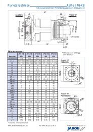
Metal bellows coupling I Series KPP - Jakob GmbH & Co ...
Metal bellows coupling I Series KPP - Jakob GmbH & Co ...
Metal bellows coupling I Series KPP - Jakob GmbH & Co ...

You also want an ePaper? Increase the reach of your titles
YUMPU automatically turns print PDFs into web optimized ePapers that Google loves.
Servo <strong>coupling</strong>s
JAKOB Antriebstechnik <strong>GmbH</strong> is an internationally<br />
leading manufacturer of Sevo <strong>coupling</strong>s, safety <strong>coupling</strong>s,<br />
and mechanical clamping elements.<br />
For more than 30 years JAKOB has been developing<br />
and producing various types of torsionally stiff metal<br />
bellow <strong>coupling</strong>s, safety <strong>coupling</strong>s and planetary<br />
gearboxes for the servo drive industry. Through our<br />
history we have earned ourselves a reputation of being<br />
a reliable and competent partner in the motion control<br />
industry.<br />
JAKOB is the market leader in the area of mechanical<br />
tool and component clamping with its innovative and<br />
The company JAKOB<br />
2D-drawings in DXF-format or 3D-models in Step format are<br />
available for download at the corresponding side of our homepage.<br />
For special dimensions or diff erent drawing types please<br />
contact JAKOB.<br />
Telephone +49(0)6022 2208-0, Telefax +49(0)6022 2208-22<br />
www.jakobantriebstechnik.de, info@jakobantriebstechnik.de<br />
unique clamping technology. The JAKOB wedge clamping<br />
technology provides the highest clamping forces<br />
with low actuation torques and, at the same time,<br />
maximum operating safety.<br />
The goal of our servo and safety <strong>coupling</strong> catalog is to<br />
provide a general overview of our standard product<br />
range. More detailed information can be obtained at<br />
our Homepage www.jakobantriebstechnik.de .<br />
Highly trained engineers and technicians at our facility<br />
in Kleinwallstadt are always ready with a solution to<br />
best meet your requirements.
<strong>Metal</strong> <strong>bellows</strong> <strong>coupling</strong>s<br />
Directory Servo <strong>coupling</strong>s I Overview<br />
KM 6-corrugation <strong>bellows</strong> simple installation with EASY-clamping hub<br />
cost-effective standard series<br />
KP 4-corrugation <strong>bellows</strong> simple installation with EASY-clamping hub<br />
short design high torsional stiffness<br />
KR straight <strong>bellows</strong> simple installation with EASY-clamping hub<br />
low restoring forces high torsional stiffness<br />
KPH<br />
KMH<br />
KRH<br />
<strong>KPP</strong> plug in design blind fi tting possible<br />
backlashfree, exakt torque transmission<br />
KG/ 4-corrugation <strong>bellows</strong> very short design up to 350°C<br />
KG-VA all-steel-version with EASY-clamping hub<br />
optional in stainless steel version (KG-VA)<br />
KGH simple installation - splitted hub design<br />
variable length up to 350°C<br />
KSD 6-corrugation <strong>bellows</strong> conical clamping hub at both sides<br />
short design cost-effective standard series<br />
KSS straight <strong>bellows</strong> conical clamping hub at both sides<br />
low restoring forces high torsional stiffness<br />
KXL for high torques up to 38.000 Nm<br />
easy to fi t by three-parted construction<br />
high torsional stiffness low moments of inertia<br />
KE fl ange hubs at both sides for variable fi tting<br />
3 standard length radial fi tting<br />
further series<br />
simple installation - splitted hub design<br />
variable length backlashfree, torsional stiff, fl exible<br />
area Safety <strong>coupling</strong>s from page 41<br />
page<br />
10<br />
11<br />
12<br />
13<br />
14 I 15<br />
16<br />
17<br />
18<br />
19<br />
20 I 21<br />
22<br />
23
Elastomer <strong>coupling</strong>s<br />
EKM plug in backlash free oscillation dampening<br />
different shore hardness with radial clamping hub<br />
cost- effective standard series<br />
ESM-A with conical hub at both sides<br />
rotary symetric design high speed<br />
further series<br />
Miniature <strong>coupling</strong>s<br />
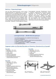
Distance <strong>coupling</strong>s<br />
MKM miniature metal <strong>bellows</strong> <strong>coupling</strong> standard series with radial clamping hub<br />
temperature range: -100°C up to +300°C<br />
MKP miniature metal <strong>bellows</strong> <strong>coupling</strong> short design<br />
with radial clamping hub temperature range: -100°C up to +300°C<br />
MKA miniature metal <strong>bellows</strong> <strong>coupling</strong> cost-effective version with set screws<br />
temperature range: -20°C up to +150°C<br />
MJT/ miniature elastomer <strong>coupling</strong><br />
MJT-C MJT-C: with radial clamping hub MJT: with set screws<br />
temperature range: -20°C up to +70°C<br />
MOH miniature oldham- type <strong>coupling</strong> temperature range: -20°C up to +100°C<br />
MOH-C MOH-C: with radial clamping hub MOH: with set screws<br />
compensation of radial shaft displacement<br />
MCJB Miniature- cardan- joint <strong>coupling</strong><br />
compensation of angular shaft displacement with radial clamping hub<br />
temperature range: -20°C up to +150°C<br />
EKZ variable length up to 3 m simple installation<br />
plug in backlash free oszillation dampening<br />
stainless version<br />
WDS variable length 0,2 up to 6 m<br />
simple installation - splitted hub design<br />
high speed, temperature range: -40°C up to +300°C<br />
WDE variable length up to 3 m<br />
cost-eff ective version with reduced operating parameters<br />
simple installation - splitted hub design<br />
page<br />
27<br />
28<br />
29<br />
30<br />
31<br />
32<br />
33<br />
34<br />
35<br />
38<br />
39<br />
40
Defi nition - servo <strong>coupling</strong>s:<br />
Servo <strong>coupling</strong>s are compensating <strong>coupling</strong>s with a<br />
backlash free and conformal torque transfer providing<br />
high torsional stiffness and a low moment of inertia.<br />
According to these requirements, JAKOB metal bellow<br />
<strong>coupling</strong>s can be regarded as the ideal solution. For<br />
more than 25 years, they have proven themselves in<br />
thousands of servo drives as being excellent. Elastomer<br />
<strong>coupling</strong>s with a fl exible polyurethan-spider can also<br />
represent a perfect alternative for different applications<br />
because of their product-specifi c advantages.<br />
The JAKOB modular system:<br />
As fl exible compensating parts, stainless steel <strong>bellows</strong><br />
are used in different forms as well as polyurethane<br />
spiders with different shore hardnesses, oldham- type<br />
spacer as polyacetal and stainless steel membrane<br />
hubs. Another important aspect is the kind of connection<br />
between the driven shafts resp. primary shafts and<br />
the <strong>coupling</strong> hubs. Several versions of backlash free<br />
frictional clamping hubs or conical hubs are available.<br />
The JAKOB <strong>coupling</strong> program is devided<br />
into the following four main groups:<br />
<strong>Metal</strong> <strong>bellows</strong> <strong>coupling</strong>s<br />
Elastomer <strong>coupling</strong>s<br />
Miniature <strong>coupling</strong>s<br />
Distance <strong>coupling</strong>s<br />
4 Servo <strong>coupling</strong>s<br />
Servo <strong>coupling</strong>s I General<br />
Characteristics - JAKOB servo <strong>coupling</strong>s:<br />
For decades, the centre of the JAKOB<br />
<strong>coupling</strong> programhas been a large variety of<br />
different metal bellow <strong>coupling</strong>s.<br />
All JAKOB servo <strong>coupling</strong>s have one thing in common,<br />
they are all backlash free (also shaft-hub-connection)<br />
and fl exible to allow the compensation of shaft misalignments.<br />
Because of the unique characteristics of the<br />
different series, the designer will (almost) always fi nd<br />
the best solution within the large-scale JAKOB <strong>coupling</strong><br />
program. The area of application ranges from highly<br />
dynamic feed drives of the axis in machine tools to high<br />
performance drives in the general machine tool design.<br />
absolutely backlash free, exact torque transfer<br />
low moment of inertia high balancing quality<br />
excellent operational characteristics high speed<br />
compensation of shaft misalignments low restoring forces<br />
frictional, easy to fi t shaft-hub-connection<br />
metal bellow: max. torsional rigidity, wear free, up to 350°C<br />
elastomer spider: plug-in, oscillation dampening, up to 120°C<br />
compact dimensions, fl exible areas of applications<br />
large number of types and sizes available (modular system)<br />
precise production best quality long life<br />
In the following, the most important and widely used<br />
series of compensating elements and kinds of hubs,<br />
derived from the numerous possibilities of combinations,<br />
are described in this catalogue. A well-contrived<br />
modular system, which provides multiple use of many<br />
parts, enables production in cost-effective batch sizes<br />
and very short delivery period.<br />
www.jakobantriebstechnik.de
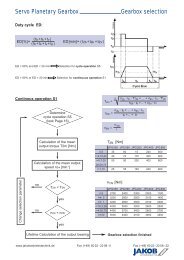
Technical information - defi nitions/details:<br />
Servo <strong>coupling</strong>s I Dimensioning<br />
Nominal torque of the <strong>coupling</strong>: TN - [Nm]<br />
The nominal torque of the <strong>coupling</strong> defi nes the max. load of the prolonged alternating-stress strength. If in<br />
normal operation T N is not exceeded, an infi nite number of operation cycles can be carried out (see d „useful<br />
life of the <strong>coupling</strong>“).<br />
Moment of inertia: JK - [10 -3 kgm 2 ]<br />
The values for the moment of inertia are defi ned for medium hub- bores in the given diameter range<br />
Dmin/Dmax. <strong>Co</strong>nversion: [ kgcm 2 ] = [10 -4 kgm 2 ]<br />
Torsional rigidity: CTK - [Nm/arc min]<br />
The values for the specifi c torsional rigidity of all <strong>coupling</strong>s are converted from the existing values [103 Nm/rad]<br />
to „Newtonmeter per angular minute“. This enables the constructor to determine the twisting angle failure quite<br />
easily (see b below) under consideration of the operating torque. 60 angular minutes (resp. arc minutes)<br />
correspond to one angular degree. This defi nes the conversion factor 1 rad = 57,3° = 3438 arcmin.<br />
<strong>Co</strong>nversion: [103Nm/rad = 0,291 Nm/arcmin] resp. [1Nm/arcmin = 3438 Nm/rad=3,44 kNm/rad]<br />
Example: Size KM 170: 17,5 Nm/arcmin= 60 kNm/rad<br />
Max. alignment of shafts: [mm]<br />
The maximum alignment of shafts is the largest allowed misalignment between drive shaft and output shaft,<br />
which results from the calculation of the prolonged alternating-stress strength for compensating elements.<br />
If the allowed displacement values are not exceeded, an infi nite number of load alternations can be carried out.<br />
In exceptional cases (e.g. during fi xing) resp. at reduced numbers of load alternations, the displacement<br />
values may be considerably higher (please contact for further consultation).<br />
axial displacement: usually without problems (expansion due to temperature)<br />
angular displacement: usually without problems - allowed max. value: 1 to 2 degrees<br />
lateral or parallel displacement: If the admissible values are considerably exceeded, permanent<br />
distortion at the <strong>bellows</strong> resp. higher wear of the elastomer spider<br />
can occur. Special care during fi tting must be taken!<br />
Spring rigidity - axial / lateral: [N/mm]<br />
Restoring forces of metal <strong>bellows</strong> or elastomer spiders, caused by shaft misalignments.<br />
Dimensioning of the <strong>coupling</strong><br />
a) according to torque:<br />
Usually the size of the <strong>coupling</strong> is chosen according to the torque. For exact determination of the necessary<br />
driving torque, diffi cult calculations are neccessary (see formularies). If the size of the motor is fi xed, the<br />
necessary nominal torque of the <strong>coupling</strong> TKN can be calculated as follows:<br />
T N > 1,25 • T A max • i TA max = peak torque of the motor<br />
i = transmission resp. reduction of the toothed belt drive resp. the spur- toothed wheel<br />
b) according to the torsional rigidity:<br />
For applications with very precise requirements (position control, transmitter), transfer errors due to high elastic<br />
deformation can be an importand criteria of selection of the <strong>coupling</strong>. The torsional angle “αT” is calculated as<br />
follows:<br />
aT = TA [arc minutes] with TA= driving torque [Nm] / CTK= torsional rigidity of the <strong>coupling</strong> [Nm/arcmin]<br />
CTK<br />
In very few cases, metal bellow <strong>coupling</strong>s can have resonance sounds (e.g. a whistling or a humming).<br />
Then <strong>coupling</strong> types with a higher torsional rigidity or vibration reducing elastomer <strong>coupling</strong>s are recommended.<br />
www.jakobantriebstechnik.de<br />
Servo <strong>coupling</strong>s 5
Servo <strong>coupling</strong>s I Dimensioning<br />
c) according to the shaft diameter:<br />
After selecting the <strong>coupling</strong> type, it must be checked whether the requested shaft diameter corresponds with<br />
the allowed diameter (Dmin / Dmax) of the hub bores. Another <strong>coupling</strong> type or size must be chosen, if the<br />
shaft diameter is overdimensioned in relation to the torque, which means it is larger than Dmax of the hub.<br />
Note: Hub bores which are smaller than “Dmin”. are possible; but an optimal transfer of the nominal torque<br />
can not be guaranteed in this case, so a reduction of drive torque is necessary.<br />
d) Useful life of the <strong>coupling</strong> - durability:<br />
The durability of JAKOB compensating <strong>coupling</strong>s is basically<br />
determined by the peak torque and the existing shaft<br />
displacement or misalignment. If the admissible maximum<br />
values for the axial, lateral and angular displacement are<br />
not exceeded, and if the operating torque at the same time<br />
is below the <strong>coupling</strong> nominal torque TKN, then the <strong>coupling</strong><br />
is within the range of prolonged alternating-stress strength<br />
limit. An infi nite number of start - stop - cycles or<br />
acceleration and deceleration can be carried out without<br />
having to expect a break - down of the <strong>coupling</strong> during<br />
operation.<br />
load change cycles<br />
e) Max. load:<br />
In special cases, the <strong>coupling</strong>s (metal bellow, membrane, elastomer spider) can be overloaded for a short time<br />
with twice the nominal torque (2 x TKN). The hub-bore-connection, however, must be calculated seperately then.<br />
f) Bearing loads:<br />
Due to the fl exibility of the compensating <strong>coupling</strong>s in all<br />
directions, considerable bearing loads are prevented, in<br />
spite of possible axial, lateral or angular displacement from<br />
the drive shaft to the output shaft. Therefore, an early<br />
breakdown or higher wear of the rolling bearing can be<br />
prevented. This means less diffi cult and expensive repairing.<br />
g) Operating temperatures:<br />
<strong>Metal</strong> bellow and membrane <strong>coupling</strong>s are, as whole metal <strong>coupling</strong>s, extremely insensitive to temperature<br />
and can be used at temperatures up to 300° C without limitation. The temperature limit of the elastomer<br />
spider is at 90°C (98 Sh-A) resp. 120°C (72 Sh-D). At high operating temperatures, an appropriate<br />
correction factor needs to be applied.<br />
h) Speeds:<br />
Due to precision machining and the rotation symmetrical design resp. the additional balance pin, the<br />
compensating <strong>coupling</strong>s are generally suitable for high speeds up to 20,000 min-1 even without additional<br />
balancing. The standard balancing quality are approx. Q 6.3 to Q 16. <strong>Co</strong>uplings with conical hubs or hubs<br />
with tapered ring can be operated with speeds over 25,000 min-1 (please contact us for further consultation).<br />
The low moment of inertia also has a positive effect.<br />
i) Maintenance and wear:<br />
<strong>Co</strong>mpensation <strong>coupling</strong>s are maintenance and wear free under normal conditions. The polyurethan spiders<br />
of the elastomer <strong>coupling</strong>s should be changed in suitable periods, if critical operation parameters are given.<br />
6 Servo <strong>coupling</strong>s<br />
torque<br />
permanent<br />
distortion<br />
endurance strength<br />
(endurance failure<br />
lateral<br />
axial<br />
angular<br />
Fatigue life<br />
of <strong>coupling</strong><br />
prolonged alternating- stress strength<br />
Misalignment<br />
www.jakobantriebstechnik.de
Alignment of shafts:<br />
Servo <strong>coupling</strong>s I Installation instructions<br />
Axial and angle displacement are usually without problems<br />
and also simple to measure. To obtain the lateral displacement<br />
it is recommended to proceed as follows:<br />
Fit a dial gauge with an appropriate holding device on one<br />
shaft end or on one hub of the <strong>coupling</strong> and bring it with the<br />
stylus onto the second shaft end or onto the second<br />
<strong>coupling</strong> half (sketch). Now the shafts are turned with the<br />
dial gauge and the defl ection is read. One half of the total<br />
defl ection is the lateral misalignment. The admissible<br />
value for the shaft displacements must be taken from the<br />
technical data sheets of the appropriate series.<br />
Shaft - hub connection<br />
The <strong>coupling</strong>s are supplied with fi nished bores as a rule, in exceptional cases they are also supplied prebored.<br />
The seat shaft/hub is to be selected as a transitional seat (example: hub bore diameter 28 G6 - shaft diameter<br />
28 k6). Prior to mounting the fi nished bore shaft end conical sleeve should be lightly oiled to prevent fretting<br />
corrosion. The <strong>coupling</strong> is then ready for assembly between the two shafts. An existing keyway in the shaft will<br />
not affect the frictional connection.<br />
a) Radial clamping hub<br />
Admissible seat clearance shaft hub: min. 0,01mm/max. 0,04mm. Very simple fi tting by tightening only one<br />
radially arranged clamping screw (DIN 912). The value for the relevant tightening torques can be found in the data<br />
sheets. One hole in the housing is suffi cient, as a rule, to tightening the clamping screw. (see EASY-clamp-sytem)<br />
b) <strong>Co</strong>nical hub / conical ring hub<br />
Admissible seat clearance shaft-hub: max. 0,02 mm Assembly of the conical bush or of the conical clamping<br />
ring with several, concentrically arranged mounting screws (as a rule 6x DIN 933). One side of the <strong>coupling</strong> is<br />
fi tted onto the shaft end by evenly tightening the screws, crosswise (to prevent uneven draw-on). The drive or<br />
output is now turned by a few revolutions, so that the shaft pinion turns in the second hub and the hub can<br />
move on the shaft for axial release. Now the 6 screws of the second hub are also evenly tightened.<br />
c) Splited hub<br />
Admissible seat clearance shaft-hub: min. 0,01mm/max. 0,04mm. Two radial clamping screws (DIN 912) are<br />
arranged mirrored. The hubs or <strong>coupling</strong>s are split and consist of two loose halves. One of the splitting hubs can<br />
be put onto the aligned shaft. Tighten clamping screws evenly, alternating between both sides (note specifi ed<br />
tightening torques). A larger opening must be provided in the housing for easy installations.<br />
d) Disassembly<br />
After releasing the 6 retaining screws, the hubs are released with 3 push-off threads each.With axially tight space<br />
conditions, it is advisable to screw in and secure the push-off-screws before fi tting. For disassembly an opening<br />
in the housing should be provided. Disassembly of radial clamping hub see EASY- clamp system page 9!<br />
e) Special notes<br />
As the metal <strong>bellows</strong> consist of thin stainless steel sheeting, special care during fi tting and disassembly<br />
is neccesarry. Damages to the <strong>bellows</strong> can render the <strong>coupling</strong> useless.<br />
Hub bores which are smaller than “Dmin” are possible; but an optimal transfer of the nominal torque<br />
can not be guaranteed in this case.<br />
at smaller shaft diameters the conical hub (larger section thickness) are additional dagged.<br />
You will fi nd further type specifi c technical details and characteristics in the data sheets.<br />
www.jakobantriebstechnik.de<br />
Servo <strong>coupling</strong>s 7
4 The radial clamping hubs<br />
5 The EASY- clamp system<br />
1. The Stainless Steel Bellow<br />
<strong>Metal</strong> <strong>bellows</strong>- Servo <strong>coupling</strong>s I Technical<br />
Advantages:<br />
absolute backlash free, conformal torque transmission<br />
extreme high torsional stiffness<br />
high fl exibility for compensation of shaft displacement<br />
minimized moment of inertia<br />
Maintenance and wear-free up to 300°C<br />
High quality precision manufactur<br />
system modules with a multiplicity different<br />
bellow variants<br />
maximized JAKOB-KNOW-HOW at the<br />
specifi c bellow dimensioning<br />
100 % fi nal inspection<br />
2. The Patented <strong>Co</strong>nnection Method<br />
Advantages:<br />
the from JAKOB developed and 1974 patented<br />
beading press in method is the optimal, backlash free<br />
connection from aluminium hubs with multi layered<br />
stainless steel <strong>bellows</strong>, alternative for this the steel or<br />
stainless steel hubs are connected via plasma welding<br />
procedure for conection with metal <strong>bellows</strong><br />
in contrast to glued connections are both connections<br />
methods at critical operating conditions (-50°C to 300°C<br />
chemicals) absolute boundless not fatigue critical<br />
and transmitted torque is sure induce in the hub<br />
3. Balancing of the Hub<br />
Advantages:<br />
the balancing bolt ensures a standard balancing<br />
quality of Q 16<br />
high speeds up to 20.000 rpm<br />
smooth running to prevent oscillations<br />
Can be specially balanced for balancing<br />
quality Q1 - Q2,5<br />
8 Servo <strong>coupling</strong>s<br />
1 The stainless steel <strong>bellows</strong><br />
2 The JAKOB <strong>Co</strong>nnection<br />
3 Balancing insert<br />
thin walled,<br />
multi- layered<br />
stainless steel <strong>bellows</strong><br />
certifi ed stainless steel sheet<br />
brass wire press- fi t<br />
connection<br />
balancing insert<br />
www.jakobantriebstechnik.de
4. The Radial Clamping Hub<br />
<strong>Metal</strong> <strong>bellows</strong>- Servo <strong>coupling</strong>s I Technical<br />
existing clamping hub made of hightensil aluminium<br />
simple radial fi tting of shaft-hub-connection<br />
secure guarantee of a backlash free, force-locked<br />
transfer of the declared value nominal torque<br />
(no keyway necessary)<br />
minimized moment of inertia, low mass,<br />
stainless design<br />
short delivery time by system modules principle<br />
hub bores (D1/D2 standard tolerance G6)<br />
customised possible<br />
at customer request completion with keyway<br />
5. The EASY-Clamp System<br />
Advantages:<br />
revolution of <strong>coupling</strong> fi tting<br />
no shortening or extension of <strong>bellows</strong><br />
grave time saving, no reoperation<br />
blind assembly possible, hole in<br />
bell housing is enough<br />
widely compensation of tolerance demerit<br />
of shaft-hub-fi t<br />
no additional tool necessary<br />
no damage of hub bores and <strong>bellows</strong> at<br />
demounting of motor<br />
The clamping hub is backlash free<br />
and positively with shaft tied.<br />
6. The conical connection<br />
Advantages:<br />
Through force amplifying (wedge principal) a<br />
safe transmission of the torque although for<br />
smaller bore sizes (hub additionally sliced) is<br />
guaranteed<br />
Backlash- and maintenance- free, actuated by<br />
no keyway necessary<br />
Rotary symetric, good balancing for high speed able<br />
Expanding cone hub for axial mountening<br />
in a hollow shaft<br />
www.jakobantriebstechnik.de<br />
Nickel Plated Socket<br />
Head Cap Screw Q10.9<br />
conical<br />
clamping hub<br />
EASY-Clamp-System<br />
The clamping hub will be elastic<br />
expandet for assembly or disassembly.<br />
conical<br />
ring hub<br />
expanding<br />
cone hub<br />
Servo <strong>coupling</strong>s 9
<strong>Metal</strong> <strong>bellows</strong> <strong>coupling</strong> I <strong>Series</strong> KM<br />
6-corrugation <strong>bellows</strong> simple installation with radial EASY-clamping hub cost- effective standard series<br />
Technical data:<br />
KM TN moment torsional max. Shaft axial lateral mass tightening torque<br />
of inertia stiffness displacement (mm) spring rate spring rate approx. of screws<br />
Size [Nm] [10 -3 kgm 2 ] [Nm/arcmin] axial ± lateral [N/mm] [N/mm] [kg] [Nm]<br />
smaller <strong>coupling</strong>s from 0,4 Nm - 12 Nm see series MKM (page 30)<br />
20 20 0,14 5,2 0,8 0,25 51 190 0,3 14<br />
35 35 0,14 5,8 0,8 0,25 51 190 0,3 14<br />
60 60 0,29 8,7 0,9 0,3 49 260 0,5 35<br />
80 80 0,79 14 1 0,3 45 280 0,8 65<br />
170 170 0,83 17 1 0,3 80 470 0,8 65<br />
270 270 2,2 32 1 0,3 70 450 1,4 115<br />
400 400 2,4 47 1 0,3 100 640 1,5 115<br />
600 600 4,7 67 1 0,3 100 980 2,2 200<br />
900 900 9 105 1 0,3 145 1000 3,3 200<br />
1300 1300 14 170 1 0,3 130 920 4,2 290<br />
1800 1800 15 260 1 0,3 250 1900 4,5 290<br />
Temperature range: -40°C up to +300°C<br />
Material: <strong>bellows</strong>: stainless steel<br />
hubs: high tensile strength aluminium<br />
screws: DIN 912 - nickel plated<br />
Dimensions [mm]: length dimensions accordin to DIN ISO 2768 cH<br />
KM Øa c f g h L ØD1/2min ØD1/2max<br />
20 56 19 M 6 30 7,5 70 9 30<br />
35 56 19 M 6 30 7,5 70 14 30<br />
60 66 22 M 8 33 8,5 77 15 34<br />
80 82 28,5 M 10 38 10,5 90 17 43<br />
170 82 28,5 M 10 40 10,5 92 22 43<br />
270 101 35 M 12 42 12 100 27 55<br />
400 101 35 M 12 48 12 106 32 55<br />
600 122 43,5 M 14 52 13,5 116 35 70<br />
900 133 47 M 14 53 18,5 143 40 75<br />
1300 157 54 M 16 55 19 145 60 85<br />
1800 157 54 M 16 55 19 145 65 85<br />
Ordering example: KM 170 - D1 = 30 G7 D2 = 35 H6<br />
10 Servo <strong>coupling</strong>s<br />
www.jakobantriebstechnik.de
<strong>Metal</strong> <strong>bellows</strong> <strong>coupling</strong> I <strong>Series</strong> KP<br />
4 corrugation <strong>bellows</strong> short design high torsional stiffness<br />
simple installation with radial EASY-clamping hub<br />
Technical data:<br />
KP TN moment torsional max. Shaft axial lateral mass tightening torque<br />
of inertia stiffness displacement (mm) spring rate spring rate approx. of screws<br />
Size [Nm] [10 -3 kgm 2 ] [Nm/arcmin] axial ± lateral [N/mm] [N/mm] [kg] [Nm]<br />
aller <strong>coupling</strong>s from 2 - 12 Nm see series MKP (page 31)<br />
20 20 0,13 9 0,5 0,2 70 450 0,3 14<br />
35 35 0,13 9 0,5 0,2 70 450 0,3 14<br />
60 60 0,27 14 0,6 0,2 70 650 0,4 35<br />
100 100 0,35 20 0,6 0,2 110 1200 0,5 35<br />
170 170 0,76 28 0,8 0,2 98 1000 0,8 65<br />
270 270 2 52 0,8 0,2 90 1300 1,3 115<br />
400 400 2,15 74 0,7 0,2 135 1500 1,4 115<br />
600 600 4,5 106 0,7 0,2 140 2800 2,1 200<br />
900 900 9,0 156 0,8 0,2 210 3050 3,5 200<br />
Temperature range: -40°C up to +300°C<br />
nur Platzhalter<br />
Material: <strong>bellows</strong>: stainless steel<br />
hubs: high tensile strength aluminium<br />
screws: DIN 912 - nickel plated<br />
Dimensions [mm]: length dimensions accordin to DIN ISO 2768 cH<br />
KP Øa c f g h L ØD1/2min ØD1/2max<br />
20 56 19 M 6 21 7,5 61 9 30<br />
35 56 19 M 6 21 7,5 61 14 30<br />
60 66 22 M 8 23 8,5 67 15 34<br />
100 71 25 M 8 23 8,5 68 22 38<br />
170 82 28,5 M 10 28 10,5 80 22 43<br />
270 101 35 M 12 29 12 87 27 55<br />
400 101 35 M 12 33 12 91 32 55<br />
600 122 43,5 M 14 36 13,5 100 35 70<br />
900 133 47 M 14 37 18,5 127 40 75<br />
Ordering example: KP 170 - D1 = 43 H7 D2 = 40 G7<br />
www.jakobantriebstechnik.de<br />
Servo <strong>coupling</strong>s 11
<strong>Metal</strong> <strong>bellows</strong> <strong>coupling</strong> I <strong>Series</strong> KR<br />
straight <strong>bellows</strong> simple installation with radial EASY-clamping hub<br />
low restoring forces high torsional rigidity long design<br />
Technical data:<br />
KR TN moment torsional max. Shaft axial lateral mass tightening torque<br />
of inertia stiffness displacement (mm) spring rate spring rate approx. of screws<br />
Size [Nm] [10 -3 kgm 2 ] [Nm/arcmin] axial ± lateral [N/mm] [N/mm] [kg] [Nm]<br />
25 25 0,12 9 0,3 0,2 150 150 0,3 14<br />
50 50 0,12 10 0,3 0,2 160 170 0,3 14<br />
65 65 0,25 12 0,3 0,3 90 80 0,4 35<br />
100 100 0,7 23 0,5 0,4 100 95 0,75 65<br />
200 200 0,84 30 0,3 0,3 220 120 0,8 65<br />
300 300 2 53 0,4 0,3 210 160 1,3 115<br />
450 450 2,15 80 0,4 0,3 300 260 1,4 115<br />
550 550 4,2 98 0,5 0,5 300 360 2 200<br />
1500 1500 13 280 0,6 0,5 520 490 4,4 290<br />
Temperature range: -40°C up to +300°C<br />
Material: <strong>bellows</strong>: stainless steel<br />
hubs: high tensile strength aluminium<br />
screws: DIN 912 - nickel plated<br />
Dimensions [mm]: length dimensions accordin to DIN ISO 2768 cH<br />
KR Øa c f g h L ØD1/2min ØD1/2max<br />
25 56 19 M 6 33 7,5 73 10 30<br />
50 56 19 M 6 33 7,5 73 16 30<br />
65 66 22 M 8 41 8,5 85 15 34<br />
100 82 28,5 M 10 50 10,5 102 16 43<br />
200 82 28,5 M 10 56 10,5 108 22 43<br />
300 101 35 M 12 65 12 123 28 55<br />
450 101 35 M 12 65 12 123 35 55<br />
550 122 43,5 M 14 72 13,5 136 35 70<br />
1500 157 54 M 16 96 19 186 60 89<br />
Ordering example: KR 100 - D1 = 35 G7 D2 = 35 G7<br />
12 Servo <strong>coupling</strong>s<br />
www.jakobantriebstechnik.de
Technical data:<br />
metal <strong>bellows</strong> <strong>coupling</strong> I <strong>Series</strong> KPH / KMH / KRH<br />
simple installation - splitted hub design<br />
backlash free, torsional stiff, fl exible<br />
stainless design variable length<br />
KPH nominal moment torsional stiff ness max. lateral shaft axial spring lateral spring mass<br />
KMH torque of inertia [Nm/arcmin] displacement [mm] rate [N/mm] rate [N/mm] approx.<br />
KRH [Nm] [10-3kgm2 Size<br />
] KPH KMH KRH KPH KMH KRH KPH KMH KRH KPH KMH KRH [kg]<br />
10 10 0,02 1,7 1,1 - 0,15 0,25 - 70 45 - 60 224 - 0,1<br />
40 40 0,2 9 5,8 10 0,2 0,25 0,2 70 51 170 190 450 170 0,5<br />
80 80 0,5 14 8,7 12 0,2 0,3 0,3 70 49 95 260 650 80 0,8<br />
200 200 1,2 25 17 30 0,2 0,3 0,3 98 80 120 470 1000 120 1,2<br />
400 400 3,0 74 47 80 0,2 0,3 0,3 135 100 260 640 1500 260 2,0<br />
• Three types: Type KPH with 4-corrugation <strong>bellows</strong> / Type KMH mit 6-corrugation <strong>bellows</strong> / Type KRH mit 2x 1-corrugation <strong>bellows</strong>.<br />
• Note: <strong>Co</strong>upling types in splitted hub design for higher torques or rather shorter length see series KGH.<br />
KPH<br />
Material: <strong>bellows</strong>: stainless steel<br />
hubs: high tensile strength aluminium<br />
screws: ISO 4762 – nickel plated<br />
Dimensions [mm]: length dimensions according to DIN ISO 2768 cH<br />
KPH<br />
KMH<br />
KRH<br />
Øa* c f<br />
g g g<br />
KPH KMH KRH<br />
h<br />
L L L<br />
KPH KMH KRH<br />
t<br />
ØD1/2<br />
min<br />
ØD1/2<br />
max<br />
10 35 21 M5 - 8 Nm 33 43 - 9 73 83 - 18 6 15<br />
40 58 36 M8 - 25 Nm 39 48 51 13 95 104 107 26 9 25<br />
80 75 47 M10 - 65 Nm 41 51 59 13 97 107 115 26 12,5 35<br />
200 89 56 M12 - 115 Nm 45,5 57,5 73 14 106 118 134 28 19 42<br />
400 109 72 M14 - 185 Nm 52,5 67,5 84 15 117 132 149 30 24 55<br />
* The projecting edge of the screw head is considered at outer diameter “a“<br />
Mounting instruction:<br />
The splitted hub design allows a easy assembly. Further simplifi cation<br />
during installation is provided because one half of the split hub is put onto<br />
the pipe. This allows that the <strong>coupling</strong> can rest on the two shaft ends.<br />
The second half of the split hub can then be mounted to the <strong>coupling</strong> by<br />
screwing it on from below with the specifi ed tightening torque. This feature<br />
makes a “one man assembly” possible. Important is the distance between<br />
the shafts must be bigger than dimension g!<br />
Ordering example:<br />
www.jakobantriebstechnik.de<br />
KPH 80 - D1 = Ø24 G7 D2 = Ø30 G7<br />
KMH 400 - D1 = Ø38 F6 D2 = Ø48 F6<br />
Servo <strong>coupling</strong>s 13
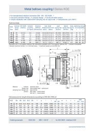
<strong>Metal</strong> <strong>bellows</strong> <strong>coupling</strong> I <strong>Series</strong> <strong>KPP</strong><br />
plug- in design simple installation EASY-clamping hub<br />
high torsional stiffness backlashfree, exakt torque transmission<br />
sturdy whole metal version temperatures up to 300°C<br />
Technical data:<br />
<strong>KPP</strong> TN moment torsional max. shaft dis- axial lateral mass tightening torque axial<br />
of inertia stiffness placement (mm) spring rate spring rate approx. of screws preload force<br />
size [Nm] [10 -3 kgm 2 ] [Nm/arcmin] axial ± lateral [N/mm] [N/mm] [kg] [Nm] approx. [N]<br />
10 10 0,033 2 0,6 0,15 20 93 0,15 8 30<br />
20 20 0,17 4,6 0,5 0,2 70 480 0,38 14 110<br />
35 35 0,17 5 0,5 0,2 70 480 0,38 14 110<br />
60 60 0,34 8 0,6 0,2 70 650 0,60 30 110<br />
100 100 0,46 12 0,6 0,2 120 1200 0,66 35 180<br />
170 170 0,90 19 0,8 0,2 100 1000 0,95 65 150<br />
270 270 2,2 31 0,8 0,2 95 1350 1,6 115 140<br />
400 400 2,4 45 0,7 0,2 135 1500 1,7 115 200<br />
600 600 5,5 67 0,7 0,2 145 3000 2,5 185 220<br />
Temperature range: -40°C up to +300°C<br />
Material: <strong>bellows</strong>: stainless steel<br />
hubs: high tensile strength aluminium<br />
screws: DIN 912 - nickel plated<br />
Dimensions [mm]: length dimensions accordin to DIN ISO 2768 cH<br />
<strong>KPP</strong> Øa Øb c f g h V L* ØD1/2min ØD1/2max<br />
10 39,5 43 13 M 5 18 6 1-1,5 62 6 20/19<br />
20 56 61 19 M 6 21 7,5 1-1,5 77,5 9 30<br />
35 56 61 19 M 6 21 7,5 1-1,5 77,5 14 30<br />
60 66 71 22 M 8 23 8,5 1-1,5 85,5 18 34<br />
100 71 75 25 M 8 23,5 8,5 1-1,5 86 22 38<br />
170 82 87 28,5 M 10 28 10,5 1-1,5 99,5 22 43<br />
270 101 106 35 M 12 29 12 1-1,5 106,5 27 55<br />
400 101 106 35 M 12 33 12 1-1,5 110,5 34 55<br />
600 122 126 43,5 M 14 36 13,5 1-1,5 120,5 35 70<br />
* delivery length (± 1mm) – without preload -> see Function page 19<br />
Note: Size <strong>KPP</strong> 1300 with conical clamping hub on request<br />
Ordering example: <strong>KPP</strong> 170 - D1 = 28 G7 D2 = 35 H7<br />
14 Servo <strong>coupling</strong>s<br />
preload<br />
www.jakobantriebstechnik.de
General:<br />
Function:<br />
<strong>Metal</strong> <strong>bellows</strong> <strong>coupling</strong> I Technics <strong>Series</strong> <strong>KPP</strong><br />
The pluggable, two-parted metal <strong>bellows</strong> <strong>coupling</strong>s<br />
are constructed for applications which are diffi cult to<br />
reach, applications without assembly boring for the<br />
clamping screws of the <strong>coupling</strong> hubs or where generally<br />
only blind fi tting is possible. For such applications,<br />
the assembly is faciliated by the axial pluggability.<br />
Also, in case of service, the disassembly is much<br />
easier, because the drive unit can be torn off „backwards“<br />
without the diffi cult loosening of the hubs.<br />
Product specifi c characteristics, which defi ne the<br />
The axial pluggability is achieved by a backlash-free<br />
carrierkeyway connection in whole metal version (aluminium<br />
anodized). For this, one hub part is delivered as a<br />
conical carrier, the counterpart with a congruent conical<br />
keyway. An additional centering element guarantees an<br />
exact alignment of both hub halves. To achieve the necessary<br />
axial prestress of the plug-in-connection, the spring<br />
tension of the metal bellow is used. For this, the bellow is<br />
pressed during assembly by 1-1,5 mm. This means, that<br />
the unstressed <strong>coupling</strong> length „l“ (see measuring table) is<br />
reduced by the prestress value „V“ after assembly.<br />
Because of the low prestress, the operativeness of the<br />
metal bellow is not reduced. The resulting residual forces<br />
usually have no negative infl uence on the shaft bearing.<br />
Assembly notes:<br />
To guarantee optimum performance of the plug-in-connection,<br />
the prestress value of 1-1,5 mm at the metal bellow<br />
must defi nitely be given special care. In most cases, it is<br />
suffi cient, if the designer considers this. Another possibility<br />
for the mechanic is, to mount the whole <strong>coupling</strong> onto the<br />
drive shaft before fi tting it to the motor (see drawing). With<br />
a depth gage the distance value „T“ from the bearing<br />
surface of the bell to the front-part of the plug-in hub can<br />
be defi ned. The mounting value „M“ on the motor wave<br />
is given by adding the distance value „T“ to the prestress<br />
value „V“. In serial use the mounting can be facilitated to<br />
a great extent by using a corresponding adjusting ring.<br />
If the angular position of the carrier to the keyway does<br />
not fi t during the plug-in, the metal bellow may be pressed<br />
for some more millimeters (this bellow deformation is<br />
allowed in exceptional cases). By slow turning of the drive<br />
shaft, the carrier fi ts the keyway in synchronous position<br />
and the <strong>coupling</strong> is ready for use.<br />
Application examble: <strong>KPP</strong>-fl ange type for direct gear extension<br />
www.jakobantriebstechnik.de<br />
metal <strong>bellows</strong> <strong>coupling</strong>s, nevertheless apply for the<br />
<strong>KPP</strong> <strong>coupling</strong>s, too. These are the absolute zero<br />
backlash, high torsional stiffness, low mass moment<br />
of inertia, compensation of misalignments as well as<br />
high operating speed and high operating temperatures.<br />
Depending on the special operation parameters, plugin<br />
elastomer <strong>coupling</strong>s of series EKM & ESM provide a<br />
very good alternative.<br />
motor<br />
adjusting ring<br />
Servo <strong>coupling</strong>s 15
<strong>Metal</strong> <strong>bellows</strong> <strong>coupling</strong> I <strong>Series</strong> KG / KG-VA<br />
4-corrugation <strong>bellows</strong> very short design torsional stiff<br />
all-steel-version – up to 350°C wear and maintenance free<br />
simple installation - with EASY-clamping hub (size 5/10/20 - optional)<br />
Technical data:<br />
KG TN moment torsional max. shaft axial lateral mass tightening torque<br />
KG-VA of inertia stiffness displacement (mm) spring rate spring rate approx. of screws<br />
size [Nm] [10 -3 kgm 2 ] [Nm/arcmin] axial ± lateral [N/mm] [N/mm] [kg] [Nm]<br />
5 5 0,004 0,9 0,3 0,1 75 400 0,06 2 (1)*<br />
10 10 0,019 2,1 0,4 0,15 85 400 0,14 5 (2,5)*<br />
20 20 0,044 3,4 0,4 0,15 55 360 0,22 10 (5)*<br />
40 40 0,18 9 0,6 0,2 70 450 0,5 16 (8)*<br />
80 80 0,44 14 0,6 0,2 70 600 0,9 40 (22)*<br />
140 140 0,74 20 0,6 0,2 110 1200 1,1 40 (22)*<br />
220 220 1,22 28 0,7 0,2 95 1000 1,5 80 (43)*<br />
350 350 2,6 52 0,8 0,2 90 1300 2,4 135 (75)*<br />
700 700 5,4 106 0,8 0,2 140 2800 3,4 135 (75)*<br />
1300 1300 24 225 0,7 0,2 160 2100 8,5 300 (180)*<br />
Material: <strong>bellows</strong>: stainless steel 1.4571<br />
KG-hubs: steel St 52<br />
KG-VA-hubs: 1.4301/V2A<br />
screws: DIN 912 – nickel plated<br />
*(optional stainless steel A4-80)<br />
Note: <strong>Co</strong>nnection between <strong>bellows</strong> and hub: plasma welding-process<br />
Dimensions [mm]: length dimensions according to DIN ISO 2768 cH<br />
KG Øa c f g h L ØD1/2min ØD1/2max<br />
KG-VA<br />
5 24 7,3 M 3 10 4,5 29 6 11<br />
10 34 10,5 M 4 16 5 38 8 16<br />
20 39,5 13 M 5 17 6 43 10 20<br />
40 56 18 M 6 23 7,5 55 12 32<br />
80 66 22,5 M 8 24 9 61 14 35<br />
140 71 27 M 8 25 9 62 18 42 [40]<br />
220 82 27,5 M 10 28 11,5 73 20 42<br />
350 101 32 M 12 30 12,5 82 22 50 [52]<br />
700 122 40 M 12 37 11,5 [13] 85 [89] 42 64 [68]<br />
1300 157 54 M 16 40 17,5 111 50 90<br />
Versions with longer metal <strong>bellows</strong> or special hubs are possible if specially required by customer.<br />
Note to <strong>Series</strong> KG-VA: Stainless steel version general without EASY pin.<br />
*Stainless steel screws possible on request (reduced tightening torques see braket values)<br />
Ordering example: KG 40 - D1 = 16 G7 D2 = 24 H7<br />
KG - VA 220 - D1 = 32 G7 D2 = 35 G7 stainless steel version<br />
KG - VA 700 - D1 = 52 G7 D2 = 52 G7 stainless steel version + stainless steel screws<br />
16 Servo <strong>coupling</strong>s<br />
alternative: KG-VA<br />
stainless steel<br />
www.jakobantriebstechnik.de
<strong>Metal</strong> <strong>bellows</strong> <strong>coupling</strong> I <strong>Series</strong> KGH<br />
simple installation - splitted hub design<br />
backlash free - torsional stiff wear and maintenance free<br />
variable length all-steel-version - up to 350°C<br />
Technical data:<br />
KGH TN moment torsional max. shaft axial lateral mass<br />
of inertia stiffness displacement (mm) spring rate springrate approx.<br />
size [Nm] [10 -3 kgm 2 ] [Nm/arcmin] axial ± lateral [N/mm] [N/mm] [kg]<br />
20 20 0,045 3,4 (6) 0,5 (0,3) 0,15 (0,1) 55 (100) 360 (2100) 0,25<br />
40 40 0,2 9 (16) 0,6 (0,3) 0,2 (0,1) 70 (130) 450 (2500) 0,6<br />
80 80 0,5 14 (26) 0,6 (0,3) 0,2 (0,1) 70 (120) 600 (3500) 0,9<br />
220 220 1,4 28 (50) 0,7 (0,4) 0,2 (0,1) 95 (170) 1000 (5000) 1,8<br />
350 350 3,0 52 (93) 0,8 (0,4) 0,2 (0,1) 90 (170) 1300 (7000) 2,8<br />
700 700 7,3 106 (190) 0,8 (0,4) 0,2 (0,1) 140 (260) 2800 (15000) 4,6<br />
1600 1600 46 225 (--) 0,7 (--) 0,2 (--) 160 (--) 2100 (--) 15<br />
Standard with 4- corrugation <strong>bellows</strong>; alternative available with 2- corrugation <strong>bellows</strong> (values in brakets)<br />
nur Platzhalter<br />
Material: <strong>bellows</strong>: stainless steel 1.4571<br />
hubs: steel St 52<br />
screws: DIN 912 – nickel plated<br />
Note: <strong>Co</strong>nnection between <strong>bellows</strong> an hub: with plasma welding-process<br />
Dimensions [mm]: length dimensions according to DIN ISO 2768 cH<br />
KGH Øa Øb c f g h L-4w L-2w t ØD1/2min ØD1/2max<br />
20 39,5 38 25,5 M 5 - 7 Nm 22 (17) 6 50 (45) 12 6 19<br />
40 56 51 36 M 6 - 16 Nm 32 (22) 7,5 66 (56) 15 12 28<br />
80 66 62 45 M 8 - 40 Nm 32 (24) 8 68 (60) 16 14 35<br />
220 82 76 55 M 10 - 80 Nm 37 (27) 11 85 (75) 22 20 42<br />
350 101 89 64 M 12 - 135 Nm 40 (29) 13 94 (83) 24 22 48<br />
700 122 108 78 M 14 - 180 Nm 47 (31) 15 107 (91) 27 35 62<br />
1600 157 145 108 2x M 16 - 290 Nm 55 (--) 18 / 30 190 (- -) 64 35 85<br />
Mounting instruction:<br />
The splitted hub design allows a easy assembly. Further simplifi cation<br />
during installation is provided because one half of the split hub is put onto<br />
the pipe. This allows that the <strong>coupling</strong> can rest on the two shaft ends.<br />
The second half of the split hub can then be mounted to the <strong>coupling</strong> by<br />
screwing it on from below with the specifi ed tightening torque. This feature<br />
makes a “one man assembly” possible.<br />
Ordering example: KGH 220/4W - D1 = 24 G7 D2 = 30 G7<br />
www.jakobantriebstechnik.de<br />
Servo <strong>coupling</strong>s 17
<strong>Metal</strong> <strong>bellows</strong> <strong>coupling</strong> I <strong>Series</strong> KSD<br />
6-corrugation <strong>bellows</strong> short design conical bush on both sides<br />
cost- effective Standard series<br />
Technical data:<br />
KSD TN moment torsional max. Shaft axial lateral mass tightening torque<br />
of inertia stiffness displacement (mm) spring rate spring rate approx. of screws<br />
Size [Nm] [10 -3 kgm 2 ] [Nm/arcmin] axial ± lateral [N/mm] [N/mm] [kg] [Nm]<br />
10 10 0,03 2,1 0,6 0,15 20 93 0,22 3<br />
20 20 0,1 5,5 0,8 0,25 51 190 0,4 4<br />
35 35 0,1 6 0,8 0,25 51 190 0,4 4<br />
60 60 0,3 9 0,9 0,3 49 260 0,8 14<br />
80 80 0,9 14 1 0,3 48 220 1,3 14<br />
170 170 0,9 18 1 0,3 80 400 1,3 14<br />
270 270 2,5 32 1 0,3 70 450 2,4 35<br />
400 400 2,8 47 1 0,3 100 640 2,5 35<br />
550 550 5,5 67 1 0,3 100 980 3,6 65<br />
900 900 10 105 1 0,3 145 1000 5,5 65<br />
1300 1300 20 170 1 0,3 130 920 7,7 115<br />
2500 2500 103 450 1 0,3 170 1350 22 290<br />
Temperature range: -40°C up to +300°C<br />
Material: <strong>bellows</strong>: stainless steel<br />
hubs: heat treated steel<br />
screws: DIN 933 - nickel plated<br />
Dimensions [mm]: length dimensions accordin to DIN ISO 2768 cH<br />
KSD Ø a Ø b Ø c e 6 x f g h L Ø D 1/2 prebored<br />
min. max.<br />
10 39,5 34 27 45 M 4 7 33 51 6 16 5<br />
20 56 52 30 48 M 4 12 44 54 10 19 8<br />
35 56 52 30 48 M 4 12 44 54 10 19 8<br />
60 66 62 36 53 M 6 5 47 61 12 24 11<br />
80 82 78 50 58 M 6 4 52 66 18 35 17<br />
170 82 78 50 60 M 6 6 54 68 18 35 17<br />
270 101 96 62 68 M 8 2 58 79 28 42 25<br />
400 101 96 62 74 M 8 8 64 85 30 42 25<br />
550 122 112 70 78 M 10 6 68 91 35 48 28<br />
900 132 127 83 94 M 10 6 76 107 40 60 34<br />
1300 157 140 98 96 M 12 6 78 111 40 70 38<br />
2500 203 194 138 147 M 16 8 97 167 50 102 49<br />
Ordering example: KSD 270 - D1 = 42 G6 D2 = 30 H7<br />
18 Servo <strong>coupling</strong>s<br />
www.jakobantriebstechnik.de
<strong>Metal</strong> <strong>bellows</strong> <strong>coupling</strong> I <strong>Series</strong> KSS<br />
straight <strong>bellows</strong> conical bush on both sides low restoring forces high torsional rigidity<br />
Technical data:<br />
KSS TN moment torsional max. Shaft axial lateral mass tightening torque<br />
of inertia stiffness displacement (mm) spring rate spring rate approx. of screws<br />
Size [Nm] [10 -3 kgm 2 ] [Nm/arcmin] axial ± lateral [N/mm] [N/mm] [kg] [Nm]<br />
25 25 0,1 10 0,3 0,2 150 150 0,4 4<br />
50 50 0,1 11 0,3 0,2 160 170 0,4 4<br />
65 65 0,3 13 0,3 0,3 90 80 0,7 14<br />
100 100 0,75 24 0,5 0,4 100 95 1,2 14<br />
200 200 0,84 30 0,3 0,3 220 120 1,25 14<br />
300 300 2,3 53 0,4 0,3 210 160 2,2 35<br />
450 450 2,4 80 0,4 0,3 300 260 2,3 35<br />
540 540 4,8 100 0,5 0,5 300 360 3,4 67<br />
850 850 18 160 0,7 0,6 200 170 7,5 115<br />
1500 1500 19 290 0,6 0,5 520 490 7,7 115<br />
2500 2500 100 700 0,4 0,5 550 590 23 290<br />
Temperature range: -40°C up to +300°C<br />
Material: <strong>bellows</strong>: stainless steel<br />
hubs: heat treated steel<br />
screws: DIN 933 - nickel plated<br />
Dimensions [mm]: length dimensions accordin to DIN ISO 2768 cH<br />
KSS Ø a Ø b Ø c e 6 x f g h L Ø D 1/2 prebored<br />
min. max.<br />
25 56 52 30 51 M 4 15 47 57 10 19 8<br />
50 56 52 30 51 M 4 15 47 57 10 19 8<br />
65 66 62 36 61 M 6 13 55 69 12 24 11<br />
100 82 78 50 70 M 6 16 64 78 18 35 17<br />
200 82 78 50 76 M 6 22 70 84 18 35 17<br />
300 101 96 62 89 M 8 25 81 100 28 42 25<br />
450 101 96 62 89 M 8 25 81 100 28 42 25<br />
540 122 112 70 98 M 10 26 88 111 35 48 28<br />
850 157 140 98 137 M 12 44 119 152 40 70 38<br />
1500 157 140 98 137 M 12 44 119 152 40 70 38<br />
2500 203 194 138 211 M 16 72 161 231 50 102 49<br />
Ordering example: KSS 450 - D1 = 28 H7 D2 = 35 F6<br />
www.jakobantriebstechnik.de<br />
Servo <strong>coupling</strong>s 19
<strong>Metal</strong> <strong>bellows</strong> <strong>coupling</strong> I <strong>Series</strong> KXL<br />
for high torques up to 65.000 Nm backlash free, exact torque transfer<br />
high torsional stiffness low moments of inertia high tolerance of shaft displacements<br />
three-parted construction easy to fi t variable in use<br />
The metal <strong>bellows</strong> <strong>coupling</strong>s of the series KXL are constructed<br />
for medium- size to big drives of up to max. 65.000 Nm.<br />
Although this type of <strong>coupling</strong> has proven itself reliable for years,<br />
the series was completely reworked in order to make it even<br />
more attractive regarding technical parameters as well as the<br />
aspect of costs. It is very special because of the three- parted<br />
construction with a fl exible intermediate piece (bellow). This<br />
intermediate piece can be disassembled. It consists of an optimal<br />
torsionally stiff stainless steel bellow with 2 bellow shafts<br />
on each side and an intermediate pipe which is variable in<br />
length. The connection with the two hubs is frictionally engaged<br />
(screws acc. to ISO 4017). Therefore, assembly is much easier<br />
as, e.g. in case of inspection or service, the heavy drive unit or<br />
the output unit need not be disassembled. The designer can<br />
chose between several hub variations (see selection table).<br />
The very good moment of inertia and the rotation symmetrical<br />
design ensure good dynamic operation characteristics.<br />
KXL-<strong>coupling</strong>s are most suitable for precise drives, such as for<br />
printing machines, cross cutters, main spindle drives, transfer<br />
axis or gearbox attachement. A transprt of media or a parallel<br />
drive chain through the <strong>coupling</strong> interior is possible.<br />
Technical data:<br />
KXL mass moments of inertia<br />
Size<br />
per hub per hub<br />
<strong>bellows</strong><br />
A/B F/G<br />
per hub<br />
A/B<br />
per hub<br />
<strong>bellows</strong><br />
F/G<br />
mA/mB mF/mG mBP JA/JB JF/FG JBP<br />
[kg] [kg] [kg] [kgm2 ] [kgm2 ] [kgm2 ]<br />
4 7,7 3,3 5,6 0,03 0,02 0,04<br />
6,5<br />
9<br />
10,9 5,7 8,0 0,07 0,04 0,08<br />
12 18,8 8 13,9 0,17 0,08 0,24<br />
18 28,8 11,5 19,7 0,36 0,18 0,46<br />
28<br />
50<br />
49,9 20 29,9 0,93 0,53 1,11<br />
Note: The specifi c parameters for the total weight resp. the total moment<br />
of inertia must be rounded off in dependence of length „L 16“.<br />
Material:<br />
<strong>bellows</strong>: stainless steel<br />
fl ange: heat-treated steel - black fi nish<br />
hubs: heat-treated steel - black fi nish<br />
KXL torques torsional spring rate max. shaft displacement<br />
nominal maximum stiffness axial angular axial ± angular radial<br />
torque torque CT<br />
Size TN [Nm] Tmax [Nm] [Nm/arcmin] Ca[N/mm] Cw[N/°] da[mm] dw[°] dr[mm]<br />
4 4.000 6.000 610 480 35 3 1,4 1,2<br />
6,5 6.500 9.000 1000 550 55 3 1,3 1,4<br />
9 9.000 13.000 1.700 650 115 3 1,3 1,5<br />
12 12.000 17.000 2.200 490 85 3,5 1,4 2,0<br />
18 18.000 25.000 3.200 500 125 3,5 1,3 2,3<br />
28 28.000 38.000 5.700 460 180 4 1,2 2,3<br />
50 50.000 65.000 11.000 570 225 4 1,2 2,5<br />
maximum temperature range: -40°C up to +300°C<br />
20 Servo <strong>coupling</strong>s<br />
radial mounting<br />
hub type<br />
“ A - A “<br />
www.jakobantriebstechnik.de
<strong>Metal</strong> <strong>bellows</strong> <strong>coupling</strong> I <strong>Series</strong> KXL<br />
Dimensions [mm]:<br />
length dimensions according to DIN ISO 2768 cH<br />
Size 4 6,5 9 12 18 28 50<br />
D1 min 70 75 80 90 110 130 150<br />
D2 max 90 100 108 130 150 170 220<br />
D3 157 168 190 205 247 296 380<br />
D5 167 198 256 273 322 406 505<br />
D7 203 236 259 319 372 460 561<br />
D8 152 183 193 208 250 325 416<br />
L1 62 70 77 85 91 105 120<br />
L2 53,5 60,5 66 74 79 93 108<br />
L3 46 50 54 62 66 78 88<br />
L4** 286 321 351 399 442 497 537<br />
L5 - 20 23 23 25 27 30<br />
L6 - 7,5 8,8 10 11,5 12,5 12,5<br />
L7 - 43 48,8 55 62 68 72,5<br />
L8 - 38 48,8 44 55 55 66,5<br />
L9 - 68 75 83 89 103 118<br />
L10** - 217 239 271 306 337 357<br />
L12** - 267 293 333 372 415 447<br />
L16* 41 50 59 80 100 110 120<br />
LA ±2 158 177 193 225 256 283 297<br />
L18 21 24 25 25 30 30 34<br />
L20** 164 188 200 232 266 288 304<br />
L21 21 24 25 25 30 30 34<br />
f<br />
12 x 12 x 12 x<br />
M10 M12 M14<br />
14 x 12 x 12 x<br />
M16 M18 M20<br />
16x<br />
M20<br />
i<br />
10x 9x 8x<br />
M10 M12 M14<br />
9x 8x 10x<br />
M14 M16 M16<br />
12x<br />
M18<br />
TA-f [Nm] 67 115 185 250 350 500 500<br />
TA-i [Nm] 67 115 185 185 250 250 350<br />
* Standard length - intermediate part:<br />
** Overall length for standard length L16<br />
Hub type F/G:<br />
attached fl ange acc. to ISO 9409 resp. customer‘s requirements -<br />
Center outside or inside. Dimensions of fl ange hub types F and G<br />
of L13, L19 and ØD6, ØD9, ØD10, ØD11, ØD12 customized.<br />
Ordering example: KXL 6,5 – AA / L4 = 318 / D1 = Ø80 H7 / D2 = = Ø90 H7<br />
KXL 13,5 – BG / L16 = 200 / D1 = Ø120 G6 / D2 = customer specifi c<br />
www.jakobantriebstechnik.de<br />
hub<br />
F-G<br />
hub<br />
A-A<br />
Hub type A:<br />
frictional, backlash free conical clamping ring connection, external<br />
free radial disassembly of the bellow part. The elongation of<br />
total length „L4“ of the intermediate pice of 4 mm at mounting<br />
is considered. (see mounting picture)<br />
hub<br />
B-B<br />
Hub type B:<br />
frictional, backlash free conical clamping ring connection, internal<br />
free radial disassembly of the bellow part is NOT possible<br />
hub<br />
A-B<br />
Hub type A/B:<br />
frictional, backlash free conical clamping ring connection,<br />
- external - internal - free radial disassembly of the bellow<br />
part is NOT possible<br />
i<br />
i<br />
f<br />
f<br />
Servo <strong>coupling</strong>s 21<br />
f<br />
i
<strong>Metal</strong> <strong>bellows</strong> <strong>coupling</strong> I <strong>Series</strong> KE<br />
fl ange hubs on both sides for variable mounting<br />
3 standard length radial mounting<br />
Technical data:<br />
KE TN moment torsional stiffness max. lateral shaft axial spring- lateral spring-<br />
of inertia [Nm/arcmin] displacement (mm) rate [N/mm] rate [N/mm]<br />
size [Nm] [10 -3 kgm 2 ] 4W 6W 2x1W 4W 6W 2x1W 4W 6W 2x1W 4W 6W 2x1W<br />
50 50 0,09 9 6 9 0,2 0,25 0,2 70 51 165 480 190 160<br />
65 65 0,22 14 9 11 0,2 0,3 0,2 70 49 90 650 260 85<br />
100 100 0,54 23 14 22 0,2 0,3 0,4 64 45 125 280 280 110<br />
200 200 0,6 28 18 34 0,2 0,3 0,2 98 80 350 1000 470 299<br />
300 300 1,7 52 33 45 0,2 0,3 0,3 94 70 212 1350 450 156<br />
450 450 1,9 74 47 66 0,2 0,3 0,2 135 100 305 1500 640 247<br />
540 540 3,7 106 67 96 0,2 0,3 0,3 145 100 300 3000 980 370<br />
900 900 8,5 156 99 - 0,2 0,3 - 210 145 - 3050 1000 -<br />
1500 1500 13,8 - 240 295 - 0,3 0,3 - 240 520 - 1500 480<br />
2500 2500 49 - 400 605 - 0,3 0,4 - 170 550 - 1300 600<br />
Temperature range: -40°C up to +300°C<br />
4W<br />
Material: <strong>bellows</strong>: stainless steel<br />
hubs: heat treated steel<br />
Dimensions [mm]: length dimensions accordin to DIN ISO 2768 cH<br />
KE øa øb øc øe H7 f L i - tightening torque mass<br />
4W 6W 2x1W [Nm] approx. [kg]<br />
50 56 52 32 25 7 35 44 47 M 4 - 4Nm 0,2<br />
65 66 62 38 28 9 41 51 59 M 6 - 14Nm 0,35<br />
100 82 78 53 40 9 44 56 68 M 6 - 14Nm 0,55<br />
200 82 78 53 40 9 46 58 74 M 6 - 14Nm 0,6<br />
300 101 96 65 50 12 53 66 89 M 8 - 35Nm 1,1<br />
450 101 96 65 50 12 57 72 89 M 8 - 40Nm 1,2<br />
540 122 111 80 63 15 66 82 102 M 10 - 65Nm 1,7<br />
900 132 127 88 68 20 77 93 - M 14 - 140Nm 3,0<br />
1500 157 140 110 88 24 - 103 144 M 16 - 220Nm 3,8<br />
2500 203 194 150 125 24 - 108 172 M 16 - 220Nm 7,1<br />
3 standard length: 4W – 4-corrugation <strong>bellows</strong> I 6W – 6-corrugation <strong>bellows</strong> I 2x1W – straigth <strong>bellows</strong><br />
Note: Further fl ange dimensions are possible on request<br />
Ordering example: KE 100 / 2 x 1W - Standard<br />
KE 450 / 4W - Øe = Ø 48H7 / 8 x M8 / Øc = Ø60 / L = 57<br />
22 Servo <strong>coupling</strong>s<br />
www.jakobantriebstechnik.de
<strong>Metal</strong> <strong>bellows</strong> <strong>coupling</strong>s I further series<br />
<strong>Series</strong> KHS with conical clamping hub<br />
„high-speed“ - version<br />
speed up to 30.000 min -1<br />
symetrical design<br />
high balance quality<br />
low mass moment of inertia<br />
stainless design<br />
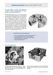
<strong>Series</strong> KPS with expanding cone hub<br />
4-corrugation <strong>bellows</strong> - short design<br />
simple installation with radial<br />
EASY- clamping hub<br />
for direct mountig in a hollow shaft<br />
internal axial buffer<br />
<strong>Series</strong> KPE with fl ange hub<br />
for standardized interface connection<br />
DIN - EN - ISO 9409 - 1<br />
two-part connection fl ange<br />
compact design<br />
sturdy whole metal version<br />
temperatures up to 300°C<br />
<strong>Series</strong> <strong>KPP</strong>-F with fl ange hub<br />
for standardized interface connection<br />
DIN - EN - ISO 9409 - 1<br />
plug in design - blind mounting<br />
possible<br />
conical clamping hub on output side<br />
mounting from „internal“<br />
temperatures up to 300°C<br />
www.jakobantriebstechnik.de<br />
Servo <strong>coupling</strong>s 23
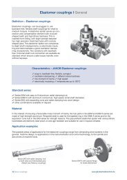
Defi nition – Elastomer <strong>coupling</strong>s:<br />
Elastomer <strong>coupling</strong>s can be plugged in, are<br />
backlash free, fl exible shaft-<strong>coupling</strong>s for small to<br />
medium torques. A elastomer spider serves as connection<br />
and compensation element with involuteshaped<br />
teeth and high Shore hardness. This is<br />
inserted form fi tting, with slight preload between<br />
two high precision machined hubs with involute<br />
shaped jaws. The elastomer spider can compensate<br />
slight shaft misalignments, is electrically insulating<br />
and demonstrates a good oscillation dampening<br />
characteristic. Two variations with backlash<br />
free, frictional shaft-hub connection are available as<br />
standard which ensure a safe torque transfer, even<br />
without keyways.<br />
Standard series:<br />
24 Servo <strong>coupling</strong>s<br />
Elastomer <strong>coupling</strong>s I General<br />
Characteristics – JAKOB Elastomer <strong>coupling</strong>s:<br />
plug-in, backlash free, fl exible, compact<br />
oscillation dampening different shore hardness<br />
low moment of inertia high speed<br />
electrically insulating temperatures up to 120°C<br />
<strong>Series</strong> EKM with easy to fi t aluminium radial clamping hub<br />
<strong>Series</strong> ESM-A with aluminium conical hub, high speed, small shaft diameters<br />
<strong>Series</strong> EKS with expanding cone and radial clamping hub, short design<br />
other combinations available on request<br />
Material:<br />
In the interest of ensuring a favourable mass moment of inertia, the hub parts in the EKM and ESM-A series are<br />
made of high-strength aluminium. Tempered steel is used for the tapered ring in the ESM-A series and for the<br />
expansion cone hub in the EKS series for strength reasons. The polyurethane elastomer spider with various Shore<br />
hardnesses are distinctly wear-proof, oil and age-resistant and suitable for use in tropical climates.<br />
Application examples:<br />
The possible areas of applications for the elastomer <strong>coupling</strong>s range from demanding drive systems in the<br />
general machine design, to applications in the instrumentation and control technology, to the spindle and<br />
axis drives of machine tools.<br />
<strong>Series</strong> EKZ with radial clamping hub<br />
at both sides and intermediate pipe<br />
(Details see Distance <strong>coupling</strong>s)<br />
<strong>Series</strong> ESM-A with special fl ange<br />
for brake attachement<br />
www.jakobantriebstechnik.de
<strong>Co</strong>upling layout:<br />
Elastomer <strong>coupling</strong>s I Dimensioning<br />
The important layout criteria are the required drive torque, the necessary torsional stiffness and the dampening<br />
characteristic of the <strong>coupling</strong>. Additionally, the minimum or maximum possible shaft diameter, the admissible<br />
temperature range, operating factors and the existing shaft misalignment, particularly the radial displacement,<br />
must be taken into consideration. Basically, the selection can be infl uenced by the <strong>coupling</strong> size and the<br />
hardness of the elastomer spider.<br />
Rough calculation formula:<br />
Roughly, the required <strong>coupling</strong> torque TK can be calculated as for the following formula:<br />
TA = drive torque [Nm]<br />
fD T = torsional stiffness factor<br />
K = T • A fD • f • T fB < TKN fT = temperature factor<br />
fB = operating factor<br />
The calculated <strong>coupling</strong> torque TK should not exceed the nominal torque of the selected <strong>coupling</strong> size.<br />
Short term overload up to twice the value of the nominal torque is admissible.<br />
The drive torque results of producer information of drive motor or can be calculated via<br />
motor output P A .<br />
Temperature factor f T:<br />
Torsional stiffness factor f D:<br />
T A = drive torque [Nm]<br />
PA = motor output [KW]<br />
nB = motor speed [min -1 ]<br />
If an exact, accurate transfer of the torque is required, as for instance with servo drives or measuring systems, a<br />
high torsional stiffness is absolutely necessary. Here the required drive torque should be multiplied with a operating<br />
factor of at least 3 to 10 when selecting the size, or a torsionally stiff metal <strong>bellows</strong> <strong>coupling</strong> selected from the<br />
extensive <strong>coupling</strong> range in this catalogue.<br />
Operating factor f B:<br />
T A = 9550 • P A<br />
n B<br />
Admissible temperature range for continuous operation<br />
PUR 98 Sh - A: -30°C bis +90°C<br />
PUR 72 Sh - D: -20°C bis +120°C<br />
Due to operating factor fB application specifi c peculiarities, such as shock loading, are taken into consideration.<br />
Application example:<br />
Note on DIN 69002 (design):<br />
operating +30°C +50°C +70°C +90°C +110°C<br />
temperature -30°C<br />
factor fT 1 1,3 1,6 1,8 2<br />
ESM-<strong>coupling</strong>: drive of a<br />
short bore spindle according<br />
to DIN 69002 (design)<br />
Technical data and dimensions of several sizes in the series ESM are according to the specifi cations of<br />
DIN 69002. Therefore, the ESM <strong>coupling</strong>s are particularly suitable for use in spindle drives (i.e. short bore<br />
spindles) for high speeds. Low mass moments of inertia and high degree of balance ensure excellent dynamic<br />
characteristics. The <strong>coupling</strong> is prepared for an axial clamping of the spindle bearing, as well as for a central<br />
coolant feed through.<br />
www.jakobantriebstechnik.de<br />
Servo <strong>coupling</strong>s 25
Assembly:<br />
The design of the ESM <strong>coupling</strong> requires mounting<br />
of the two hub halves on the shaft ends before the<br />
actual plug-in assembly. Here it must be noted, that<br />
the mounting screws are tightened evenly crosswise,<br />
to prevent surface distortion of the conical clamping<br />
ring. <strong>Co</strong>uplings of the EKM series, on the other hand,<br />
can be completely assembled before the hub<br />
mounting. For mounting the EKM hub only a radially<br />
arranged clamping screw must be tightened.<br />
Chamfered edges at the face basically also enable a<br />
blind assembly with both versions. Due to the obligatory<br />
preclamping of the elastomer, an axial assembly force<br />
must be applied during the sliding together of the <strong>coupling</strong> spider and the jaws. This assembly force can be minimised<br />
by slight oiling of the spider. For disassembly of the ESM conical hub, pushoff threads are provided for releasing<br />
the clamping ring. The relevant tightening torques of the retaining screws can be found in the technical data<br />
sheets. The seat shaft-hub is to be selected as transitional seat (e.g. bore Ø28 G6 / shaft Ø28 k6).<br />
Admissible seat clearance shaft / hub: <strong>Series</strong> ESM-A: max 0,02 mm <strong>Series</strong> EKM: min 0,01 mm/max 0,04 mm<br />
(see installation instructions page 7)<br />
Notes:<br />
The dampening capability of the elastomer spider protects the drive to a high extent from dynamic overload. Both<br />
<strong>coupling</strong> halves are always forced to move (min. 3xTN) because of the jaw construction, even if the spider<br />
should break down totally (e.g. safety instructions - vertical axis).<br />
Because of the deformation of the elastomer spider under operation conditions, the housing (bell) should<br />
be approximately 5 % bigger than the outer diameter of the <strong>coupling</strong> itself.<br />
To ensure satisfactory function, the dimension „g“ should be complied with as exactly as possible. The distance<br />
of the two shaft ends can certainly be smaller than „g“ under consideration of the measurements „m“ and<br />
„n“ of the spider.<br />
For additional price, the radial clamping hubs can also be equipped with the easy-to-fi t „Easy-Clamp-System“<br />
upon request (see also page 9).<br />
For smaller shaft diameters, the conical hub of ESM-<strong>coupling</strong>s is additionally slitted.<br />
Dimensions - Elastomerspider [mm]:<br />
Size øs øm n o øp +0,5<br />
8/10 32 10,5 2 10 8,5<br />
15/17/20/25 40 18 3 12 9,5<br />
30/43/45/50 50 27 3 14 12,5<br />
60/90 55 27 3 14 12,5<br />
150/200 65 30 4 18 16,5<br />
300/320/400 80 38 4 18 16,5<br />
500 100 47 5 22 20,5<br />
700/1000 120 58 6 25 22,5<br />
Material:<br />
Polyurethan<br />
98 Shore – A / Farbe: red<br />
72 Shore – D / Farbe: white<br />
different shore hardness available on request<br />
26 Servo <strong>coupling</strong>s<br />
Elastomer <strong>coupling</strong>s I Installation instructions<br />
alternating side<br />
distance knobs<br />
elastic deforming through<br />
axial assembly force<br />
Assembly procedure<br />
elastische backlash Verformung free due durch to<br />
axiale elastic Montagekraft distortion<br />
Note: If required by the customer for special application<br />
(e.g. longer shaft plug in depth), diameter „p“ of the<br />
inner bore of the spider can be extended up to max.<br />
Øm-2mm (upon request ).<br />
www.jakobantriebstechnik.de
Material: elastomer spider: polyurethane<br />
hubs: high tensile strength aluminium<br />
screws: DIN 912 – nickel plated<br />
Elastomer <strong>coupling</strong> I <strong>Series</strong> EKM<br />
with clamping hub on both sides plug in backlash free<br />
cost-effective standard series<br />
Technical data:<br />
EKM<br />
size<br />
TN<br />
[Nm]<br />
hardess<br />
[Shore]<br />
moment torsional stiffness max. shaft dis- radial mass tightening torque<br />
of inertia (stat. at 0,5 x T ) placement (mm) spring rate approx. of screws<br />
N<br />
[10-3kgm2 ] [Nm/arcmin] axial ± lateral [N/mm] [kg] [Nm]<br />
8 8 98 Sh-A 0,01 0,04 0,5 0,10 600 0,06 4<br />
15 15 98 Sh-A 0,03 0,24 0,5 0,10 2100 0,12 8<br />
20 20 72 Sh-D 0,03 0,34 0,5 0,07 2900 0,12 8<br />
30 30 98 Sh-A 0,09 0,41 0,5 0,10 2500 0,21 14 (8)*<br />
45 45 72 Sh-D 0,09 0,58 0,5 0,07 3600 0,21 14<br />
60 60 98 Sh-A 0,18 0,61 0,5 0,10 2600 0,32 35<br />
90 90 72 Sh-D 0,18 0,90 0,5 0,07 3700 0,32 35 (14)*<br />
150 150 98 Sh-A 0,38 1,05 1 0,10 3300 0,52 67 (35)*<br />
200 200 72 Sh-D 0,38 1,50 1 0,07 4600 0,52 67 (35)*<br />
300 300 98 Sh-A 1,0 2,00 1 0,12 4500 0,9 115 (67)*<br />
400 400 72 Sh-D 1,0 2,85 1 0,10 6500 0,9 115 (67)*<br />
500 500 98 Sh-A 2,2 5,80 1 0,15 5900 1,5 115<br />
700 700 98 Sh-A 5,2 8,00 1 0,15 7000 2,5 185<br />
1000 1000 72 Sh-D 5,2 12,0 1 0,10 9600 2,5 185<br />
Dimensions [mm]: length dimensions according to DIN ISO 2768 cH<br />
EKM Ø a c e f g h L Ø D 1/2 Ø D 1/2 Ø D 1/2<br />
min. max. prebored<br />
8 32 10,5 13,5 M 4 13 6 40 8 15 6<br />
15 40 13 17 M 5 16 8 50 10 20 7<br />
20 40 13 17 M 5 16 8 50 12 20 7<br />
30 50 16,5 (18)* 20 M 6 (M 5)* 18 9 58 13 26 (30)* 9<br />
45 50 16,5 20 M 6 18 9 58 18 26 9<br />
60 60 19,5 22 M 8 18 10 62 15 29 12<br />
90 60 19,5 (20)* 22 M 8 (M 6)* 18 10 62 20 29 (32)* 12<br />
150 70 23 (25)* 26,5 M10 (M 8)* 20 12 73 22 33 (38)* 15<br />
200 70 23 (25)* 26,5 M 10 (M 8)* 20 12 73 26 33 (38)* 15<br />
300 85 29 (30)* 31 M 12 (M 10)* 24 14 86 30 42 (48)* 18<br />
400 85 29 (30)* 31 M 12 (M 10)* 24 14 86 35 42 (48)* 18<br />
500 100 36 33 M 12 28 16 94 38 56 20<br />
700 120 44 38 M 14 33 18 109 40 70 24<br />
1000 120 44 38 M 14 33 18 109 48 70 24<br />
*CAUTION: state alternative separately while ordering (for larger shaft diameters)<br />
Ordering example: EKM 90 - D1 = 24 G7 D2 = 27 H6<br />
www.jakobantriebstechnik.de<br />
Servo <strong>coupling</strong>s 27
Elastomer <strong>coupling</strong> I <strong>Series</strong> ESM-A<br />
with conical hub and clamping ring plug in backlash free<br />
rotary symetric design high speed<br />
Technical data:<br />
ESM-A<br />
size<br />
TN<br />
[Nm]<br />
moment torsional stiffness max. shaft dis- radial mass tightening torqe max.<br />
hardness<br />
of inertia (stat. at 0,5 x T ) placement (mm) spring rate approx. of screws speed<br />
N<br />
[Shore] [10-3kgm2 ] [Nm/arcmin] axial ± lateral [N/mm] [kg] [Nm] [min-1 ]<br />
10 10 98Sh-A 0,015 0,04 0,5 0,1 600 0,11 1,8 30.000<br />
17 17 98Sh-A 0,05 0,24 0,5 0,1 2100 0,28 4 24.000<br />
25 25 72Sh-D 0,06 0,35 0,5 0,07 2900 0,28 4 24.000<br />
43 43 98Sh-A 0,19 0,40 0,5 0,1 2500 0,4 8 19.000<br />
50 50 72Sh-D 0,19 0,58 0,5 0,07 3600 0,4 8 19.000<br />
60 60 98Sh-A 0,28 0,60 0,5 0,1 2600 0,6 8 17.500<br />
90 90 72Sh-D 0,28 0,90 0,5 0,07 3700 0,6 8 17.500<br />
150 150 98Sh-A 0,65 1,05 1 0,1 3300 0,9 8 15.000<br />
200 200 72Sh-D 0,65 1,52 1 0,07 4600 0,9 8 15.000<br />
320 320 98Sh-A 2,0 2,0 1 0,12 4500 1,9 35 12000<br />
400 400 72Sh-D 2,0 2,85 1 0,1 6500 1,9 35 12.000<br />
500 500 98Sh-A 5,6 5,8 1 0,15 5900 4,5 67 9.500<br />
700 700 98Sh-A 13,0 8,0 1 0,15 7000 7,0 115 8.000<br />
1000 1000 72Sh-D 13,0 12,0 1 0,10 9600 7,0 115 8.000<br />
Material: elastomer spider: polyurethane<br />
conical hub: high tensile aluminium<br />
clamping ring: heat treated steel - black fi nish<br />
screws: DIN 912 – nickel plated<br />
Dimensions [mm]: length dimensions according to DIN ISO 2768 cH<br />
ESM-A Ø a c e f g k L Ø D 1/2 Ø D 1/2 Ø D 1/2<br />
min. max. prebored<br />
10 32 17 18,5 4x M 3 13 15,5 50 6 14 5<br />
17 40 22 25 6x M 4 16 21 66 9 19 9<br />
25 40 22 25 6x M 4 16 21 66 10 19 9<br />
43 50 29 30 4x M 5 18 25 78 12 24 10<br />
50 50 29 30 4x M 5 18 25 78 15 24 10<br />
60 55 30 30 4x M 5 18 25 78 13 26 12<br />
90 55 30 30 4x M 5 18 25 78 16 26 12<br />
150 65 40 35 8x M 5 20 30 90 17 36 12<br />
200 65 40 35 8x M 5 20 30 90 19 36 12<br />
320 80 46 45 4x M 8 24 40 114 20 40 18<br />
400 80 46 45 4x M 8 24 40 114 25 40 18<br />
500 100 58 55 4x M 10 28 49 138 22 48 20<br />
700 120 72 61 4x M 12 33 54 155 25 60 24<br />
1000 120 72 61 4x M 12 33 54 155 25 60 24<br />
Ordering example: ESM-A 150 - D1 = 17 G7 D2 = 22 H6<br />
28 Servo <strong>coupling</strong>s<br />
www.jakobantriebstechnik.de
<strong>Co</strong>mbination EKM – ESM<br />
for connection of shafts with very<br />
different diameters<br />
to facilitate the assembly of<br />
shaft-hub-connections:<br />
1.) ESM - hub from inside<br />
2.) plug- in assembly - elastomer spider<br />
3.) EKM - hub radially from outside<br />
to achieve an fi tting intermediate length<br />
Axial stop design<br />
by additional snap ring at the periphery<br />
Elastomer <strong>coupling</strong>s I further series<br />
for taking up resp. supporting large axial forces<br />
nevertheless compensation of parallel and<br />
angular misalignment<br />
might also be used for easier mounting<br />
<strong>Series</strong> EKH<br />
simple installation - splitted hub design<br />
can be combined with EKM - hub<br />
or rather ESM-A - hub<br />
mountable without disassembly<br />
of motor<br />
<strong>Series</strong> EKS with expanding cone<br />
short design for hollow - shaft - assembly<br />
7 sizes from 8 - 700 Nm<br />
variable conical shaft diameter<br />
data sheet on reques ore see homepage:<br />
www.jakobantriebstechnik.de<br />
www.jakobantriebstechnik.de<br />
Servo <strong>coupling</strong>s 29
Miniature-metal <strong>bellows</strong> <strong>coupling</strong> I <strong>Series</strong> MKM<br />
standard series with radial clamping hub<br />
temperature range: -40°C up to +300°C<br />
Technical data:<br />
MKM TN max. moment torsional max. shaft spring rate mass tightening torque<br />
speed of inertia stiffness displacement (mm) [N/mm] approx. of screws<br />
size [Nm] [min -1 ] [10 -6 kgm 2 ] [10 -3 Nm/arcmin] axial ± lateral axial lateral [g] [Nm]<br />
0,4 0,4 20.000 0,3 50 0,35 0,2 10 15 10 1<br />
0,9 0,9 20.000 0,4 90 0,3 0,2 21 26 12 1<br />
2 2 12.000 3,0 230 0,5 0,2 15 15 30 2<br />
4 4 12.000 3,0 460 0,4 0,2 35 65 40 2<br />
7 7 12.000 14 1100 0,6 0,25 45 60 80 4<br />
8 8 12.000 26 1350 0,8 0,30 16 24 130 7<br />
12 12 12.000 30 2050 0,7 0,25 40 70 140 7<br />
Material: <strong>bellows</strong>: stainless steel<br />
hubs: high tensile strength aluminium<br />
screws: DIN 912 - nickel plated<br />
Dimensions [mm]: length dimensions according to DIN ISO 2768 cH<br />
MKM Øa b c f h L ±0,5 ØD1/2min ØD1/2max<br />
0,4 16,5 9 4,6 M 2,5 3,3 30 3 6,35<br />
0,9 16,5 9 4,6 M 2,5 3,3 31,5 3 6,35<br />
2 24,5 (27,5) 13 7,5 (9,6) M 3 4,4 42 3 10 (14)<br />
4 24,5 (27,5) 13 7,5 (9,6) M 3 4,4 43,5 5 10 (14)<br />
7 34 14 11 M 4 5 57 6 17<br />
8 39,5 (44,5) 16,5 13 (15,5) M 5 6 60 6 19 (24)<br />
12 39,5 (44,5) 16,5 13 (15,5) M 5 6 62 6 19 (24)<br />
On request the couplungs from size 2-12 are avaiable with EASY-clamp (see page 9).<br />
Stock bores D1/D2 (G7)<br />
MKM Ø3 Ø4 Ø5 Ø6 Ø6,35 Ø8 Ø9,53 Ø10 Ø12 Ø15 Ø16 Ø19<br />
0,4/0,9 • • • • •<br />
2/4 • • • • • • •<br />
7 • • • • • • • •<br />
8/12 • • • • • • • • •<br />
Note: Further boresizes are possible on request.<br />
Ordering example: MKM 0,9 - D1 = 4 H7 D2 = 5 G7<br />
30 Servo <strong>coupling</strong>s<br />
www.jakobantriebstechnik.de
Miniature-metal <strong>bellows</strong> <strong>coupling</strong> I <strong>Series</strong> MKP<br />
short design with radial clamping hub<br />
temperature range: -40°C up to +300°C<br />
Technical data:<br />
MKP TN max. moment torsional max. shaft spring rate mass tightening torque<br />
speed of inertia stiffness displacement (mm) [N/mm] approx. of screws<br />
size [Nm] [min -1 ] [10 -6 kgm 2 ] [10 -3 Nm/arcmin] axial ± lateral axial lateral [g] [Nm]<br />
2 2 12.000 2,5 400 0,3 0,1 32 100 30 2<br />
5 5 12.000 2,8 800 0,3 0,1 70 400 40 2<br />
7 7 12.000 12 1700 0,4 0,15 70 220 80 4<br />
8 8 12.000 25 2100 0,5 0,15 20 90 125 7<br />
12 12 12.000 28 2600 0,4 0,15 45 190 130 7<br />
25 25 12.000 64 4000 0,5 0,15 36 180 180 8<br />
Material: <strong>bellows</strong>: stainless steel<br />
hubs: high tensile strength aluminium<br />
screws: DIN 912 - nickel plated<br />
Dimensions [mm]: length dimensions according to DIN ISO 2768 cH<br />
MKP Øa b c f h L ±0,5 ØD1/2min ØD1/2max<br />
2 24,5 (27,5) 13 7,5 (9,6) M 3 4,4 35 3 10 (14)<br />
5 24,5 (27,5) 13 7,5 (9,6) M 3 4,4 36 6 10 (14)<br />
7 34 14 11 M 4 5 47 6 17<br />
8 39,5 (44,5) 16,5 13 (15,5) M 5 6 51 6 19 (24)<br />
12 39,5 (44,5) 16,5 13 (15,5) M 5 6 51 6 19 (24)<br />
25 50 17 17 M 5 6 58 10 28<br />
On request all couplungs are avaiable with EASY-clamp (see page 9).<br />
Stock bores D1/D2 (G7)<br />
MKP Ø4 Ø5 Ø6 Ø6,35 Ø8 Ø9,53 Ø10 Ø12 Ø15 Ø16 Ø19 Ø24<br />
2/5 • • • • • • •<br />
7 • • • • • • • •<br />
8/12 • • • • • • • • •<br />
25 • • • •<br />
Note: Further boresizes are possible on request.<br />
Ordering example: MKP 5 - D1 = 4 G7 D2 = 12 G7<br />
www.jakobantriebstechnik.de<br />
Servo <strong>coupling</strong>s 31
Miniature-metal <strong>bellows</strong> <strong>coupling</strong> I <strong>Series</strong> MKA<br />
cost- effective version with set screws<br />
temperature range: -20°C up to +150°C<br />
Technical data:<br />
MKA TN max. moment torsional max. shaft spring rate mass tightening torque<br />
speed of inertia stiffness displacement (mm) [N/mm] approx. of screws<br />
size [Nm] [min -1 ] [10 -6 kgm 2 ] [10 -3 Nm/arcmin] axial ± lateral axial lateral [g] [Nm]<br />
0,4 0,4 20.000 0,19 50 0,2 0,1 10 15 8 1<br />
0,9 0,9 20.000 0,19 90 0,2 0,1 21 26 10 1<br />
2 2 12.000 2,9 230 0,2 0,1 15 15 32 4<br />
4 4 12.000 3,2 460 0,2 0,1 35 65 37 4<br />
6 6 12.000 16 1.100 0,25 0,25 45 60 85 8<br />
8 8 12.000 28 1.300 0,3 0,25 16 24 120 10<br />
Material: <strong>bellows</strong>: stainless steel<br />
hubs: high tensile strength aluminium<br />
set screws: DIN 916<br />
Dimensions [mm]: length dimensions according to DIN ISO 2768 cH<br />
MKA Øa b f h L ±0,5 ØD1/2min ØD1/2max<br />
0,4 16 7 2x M 3 2,3 26 3 8<br />
0,9 16 7 2x M 3 2,3 27,5 3 8<br />
2 25 11 2x M 4 3,5 38 5 15<br />
4 25 11 2x M 4 3,5 39,5 5 15<br />
6 35 12,5 2x M 5 4,3 54 6 20<br />
8 41 14 2x M 6 5 54,5 6 26<br />
Stock bores D1/D2 (G7)<br />
MKA Ø3 Ø4 Ø5 Ø6 Ø6,35 Ø8 Ø9,53 Ø10 Ø12 Ø15 Ø16 Ø19 Ø24<br />
0,4/0,9 • • • • • •<br />
2/4 • • • • • • • •<br />
6 • • • • • •<br />
8 • • • • • • • •<br />
Note: Further boresizes are possible on request.<br />
For a easier disassemblage we recommend to have end faces on the shaft.<br />
Ordering example: MKA 2 - D1 = 6 G7 D2 = 8 G7<br />
32 Servo <strong>coupling</strong>s<br />
www.jakobantriebstechnik.de
Miniature-elastomer <strong>coupling</strong> I <strong>Series</strong> MJT/MJT-C<br />
MJT-C: standard series with radial clamping hub MJT: cost-effective version with set screws<br />
plug in and oscillation dampening temperature range: -20°C up to +70°C<br />
Technical data:<br />
MJT/ TN max. moment torsional max. shaft dis- mass tightening torque<br />
MJT-C speed of inertia stiffness placement (mm) approx. of screws<br />
size [Nm] [min -1 ] [10 -6 kgm 2 ] [10 -3 Nm/arcmin] axial ± lateral [g] [Nm]<br />
MJT MJT-C MJT MJT-C f i<br />
14-B 0,7 27.000 11.000 0,21 0,16 3 0,6 0,15 7 0,7 0,5<br />
20-B 1,8 20.000 7.500 1,0 1,1 5 0,8 0,20 18 0,7 1<br />
30-B 4 13.000 5000 5,9 6,2 13 1,0 0,20 48 1,7 2,5<br />
14-R 2 27.000 11.000 0,21 0,16 7 0,6 0,10 7 0,7 0,5<br />
20-R 5 19.000 7.500 1,0 1,1 16 0,8 0,10 18 0,7 1<br />
30-R 12,5 13.000 5.000 5,9 6,2 38 1,0 0,10 48 1,7 2,5<br />
Dimensions [mm]: length dimensions according to DIN ISO 2768 cH<br />
MJT/MJT-C Øa c e g h L f i<br />
14 14 4 7 8 3,5 22 2x M3 M2<br />
20 20 6,5 10 10 5 30 2x M3 M2,5<br />
30 30 10 11 13 5,5 35 2x M4 M4<br />
Stock bores D1/D2 (G7) • MJT o MJT-C<br />
MJT/MJT-C Ø3 Ø4 Ø5 Ø6 Ø6,35 Ø8 Ø9,53 Ø10 Ø12 Ø14<br />
14 • o • o • o •<br />
20 o • o • o • o • o • •<br />
30 • o • o • o • o •<br />
Note: Further boresizes are possible on request.<br />
For a easier disassemblage of the MJT size we<br />
recommend to have end faces on the shaft.<br />
Ordering example: MJT-B30 - D1 = 8 H8 D2 = 10 H8 MJT-C-R 20 - D1 = 5 H8 D2 = 6 H8<br />
www.jakobantriebstechnik.de<br />
<strong>Series</strong> MJT<br />
Material:<br />
hubs: aluminium<br />
elastomerspider: polyurethane<br />
B 80-Sh-A (blue), R 98-Sh-A (red)<br />
<strong>Series</strong> MJT-C<br />
temperature correction for nominal torques<br />
-20°C bis +30°C +50°C +70°C<br />
100% 75% 60%<br />
Servo <strong>coupling</strong>s 33
Miniature-Oldham-type <strong>coupling</strong> I <strong>Series</strong> MOH/MOH-C<br />
compensation of radial shaft displacement plug in temperature range: -20°C up to +100°C<br />
MOH-C: standard series with radial clamping hub MOH: cost-effective version with set screws<br />
Technical data:<br />
MOH/ TN max. moment torsional max. displacement mass tightening torque<br />
MOH-C speed of inertia stiffness radial angular approx. of screws<br />
size [Nm] [min -1 ] [10 -6 kgm 2 ] [10 -3 Nm/arcmin] [mm] [ °] [g] [Nm]<br />
MOH MOH-C MOH MOH-C f i<br />
16 1 8.000 0,24 0,32 19 1 2 7 10 1 1<br />
20 1,5 7.000 0,81 0,82 35 1,5 2 14 16 1,7 1<br />
25 2,5 6.000 1,8 2,6 58 2 2 20 34 1,7 1,5<br />
32 7 4.800 6,7 8,3 180 2,5 2 48 80 4 2,5<br />
43 15 4.000 39 20 340 3 2 160 160 4 5<br />
Dimensions [mm]: length dimensions according to DIN ISO 2768 cH<br />
MOH/ Øa b c h L f i<br />
MOH-C MOH MOH-C MOH MOH-C MOH MOH-C<br />
16 16 8 9,5 5 2,3 3 18 21 1 x M 3 M 2,6<br />
20 20 9 10 6,5 3,3 3 20 22,5 1 x M 4 M 2,6<br />
25 25 11,5 12 8 3 4 25,5 26,5 2 x M 4 M 3<br />
32 32 14,5 16 11 4 5 32 35 2 x M 5 M 4<br />
43 43 24 21,5 15 7 7 52 47 2 x M 5 M 5<br />
Stock bores D1/D2 (H8)<br />
Material:<br />
hub: aluminium - alloy<br />
spacer: polyacetal<br />
MOH/MOH-C Ø3 Ø4 Ø5 Ø6 Ø6,35 Ø8 Ø9,53 Ø10 Ø12 Ø14 Ø15 Ø16 Ø19<br />
16 • • • •<br />
20 • • • • •<br />
25 • • • • • •<br />
32 • • • • • • • •<br />
43 • • • • • • • • • •<br />
Note: Further boresizes are possible on request.<br />
Ordering example: MOH 25 - D1 = 8 H8 D2 = 10 H8 MOH-C 35 - D1 = 10 H8 D2 = 12 H8<br />
34 Servo <strong>coupling</strong>s<br />
<strong>Series</strong> MOH<br />
<strong>Series</strong> MOH-C<br />
Temperature correction for nominal torques<br />
-20°C up to +30°C +40°C +60°C +100°C<br />
100% 80% 60% 50%<br />
www.jakobantriebstechnik.de
Miniature-cardan-joint <strong>coupling</strong> I <strong>Series</strong> MCJB<br />
compensation of angular shaft displacement with radial clamping hub<br />
temperature range: -20°C up to +150°C<br />
Technical data:<br />
MCJB TN max. moment torsional max. shaft displacement mass tightening torque<br />
speed of inertia stiffness parallel angular approx. of screws<br />
size [Nm] [min -1 ] [10 -6 kgm 2 ] [10 -3 Nm/arcmin] [mm] [ °] [g] [Nm]<br />
20 0,5 5.000 1,3 88 0,5 7 20 1<br />
25 1 5.000 3,4 204 0,5 7 35 1,5<br />
32 2 4.500 12 277 0,5 7 75 2,5<br />
40 5 3.500 33 350 0,5 7 145 4<br />
Material: hubs: aluminium - alloy<br />
cardan joint: stainless steel<br />
Dimensions [mm]: length dimensions according to DIN ISO 2768 cH<br />
MCJB Øa b c h L t g f<br />
20 20 8 6,5 3 26,5 5,5 2,2 M 2,6<br />
25 25 10,5 7,8 3,6 33,5 7 2,8 M 3<br />
32 32 13,5 10,5 4,5 43 9,5 3,6 M 4<br />
40 40 16 12,8 6 51 11,5 4,5 M 5<br />
Stock bores D1/D2 (H8)<br />
MCJB Ø4 Ø5 Ø6 Ø6,35 Ø8 Ø9,53 Ø10 Ø12 Ø14 Ø15<br />
20 • • • • •<br />
25 • • • • • •<br />
32 • • • • • •<br />
40 • • • • • •<br />
Note: Further boresizes are possible on request.<br />
Application example: Miniature-cardan shaft<br />
Ordering example: MCJB 32 - D1 = 8 H8 D2 = 10 H8<br />
www.jakobantriebstechnik.de<br />
Servo <strong>coupling</strong>s 35
Defi nition - distance <strong>coupling</strong>s:<br />
This category comprises several <strong>coupling</strong> series which<br />
can span axial distances up to 6 m of length. The<br />
common main characteristic feature of all types is a<br />
intermediate pipe resp. a metal bellow part, which is<br />
variable in length and can fi t exactly the required<br />
applications of the customer. In many cases, they can<br />
be used as spacer shaft (synchronizing shaft) and can<br />
substitute conventionel constructions of intermediate<br />
<strong>Series</strong> EKZ<br />
length L = 0,2 - 3 m<br />
6 sizes up to 700 Nm<br />
T max = 100°C<br />
elastomer spider<br />
plug-in sliding hub<br />
oscillation dampening<br />
costeffective type<br />
for medium speed<br />
<strong>Series</strong> WDS<br />
length L = 0,2 - 6 m<br />
7 sizes up to 1600 Nm<br />
T max = 300°C<br />
metal bellow<br />
integrated cardan joint<br />
big pipe diameter for<br />
max. speed<br />
high torsional stiffness<br />
pipe connection detachable<br />
-> in house production of<br />
the pipe is possible<br />
Distance <strong>coupling</strong>s I General<br />
Characteristics – JAKOB-distance <strong>coupling</strong>s:<br />
as connecting shaft without additional intermediate bearing<br />
up to 6 m axial distance<br />
high torsional stiffness backlash free, exact torque transfer<br />
compensation of displacements<br />
very easy to fi t stainless design maintenance free<br />
high speed<br />
EKZ - <strong>coupling</strong> for<br />
lifting table drive<br />
shafts with complicated additional intermediate bearings.<br />
Misalignments, especially parallel misalignments,<br />
can be compensated to a higher extend.<br />
Further more the stainless material and the easy<br />
assembly of all series must be emphasized. A secure,<br />
frictional connection with easy operation is given<br />
because of the hub design in half-shell version (series<br />
WDS, WDE) resp. with sliding hub (series EKZ).<br />
The customer can chose between three standard series with aluminium intermediate pipe:<br />
36 Servo <strong>coupling</strong>s<br />
<strong>Series</strong> WDE<br />
length L = 0,2 - 3 m<br />
5 sizes up to 500 Nm<br />
T max = 100°C<br />
metal bellow<br />
integrated cardan joint<br />
costeffective type with<br />
reduced operating parameters<br />
WDS - <strong>coupling</strong> for<br />
multi- axis linear module<br />
www.jakobantriebstechnik.de
Assembly:<br />
Distance <strong>coupling</strong>s I Assembly<br />
The splitted hub-, or the shifting hub design allows for an easy assembly. Further simplifi cation during installation<br />
is provided because one half of the split hub is screwed onto the pipe. This allows that the <strong>coupling</strong> can rest<br />
on the two shaft ends. The second half of the split hub can be then mounted to the <strong>coupling</strong> by screwing it on<br />
from below with the specifi ed tightening torque. This feature makes a “one man assembly” possible even with<br />
extremely long <strong>coupling</strong>s. During maintenance, the WB <strong>coupling</strong> can be exchanged without disassembling the<br />
drive or output units.<br />
Formula for length determination:<br />
L = A + t1 + t2 [mm]<br />
<strong>Series</strong> EKZ<br />
plug in hub<br />
clamp-connection<br />
with shiftin seat<br />
to pipe end<br />
<strong>Series</strong> WDS<br />
splitted hub<br />
design<br />
removeable<br />
connection to pipe<br />
<strong>Series</strong> WDE<br />
splitted hub<br />
design<br />
glued connection<br />
to pipe<br />
www.jakobantriebstechnik.de<br />
A = shaft seperation ± 1<br />
t = plug in depth ± 1<br />
(see data sheets)<br />
mounting length - intermediate pipe<br />
Note: The intermediate pipe can be delivered in different types of<br />
material and section thickness, as well as for high speed in<br />
straightened and balanced quality. At high speed and con<br />
current big pipe length the custom- designed optimized<br />
CFK - intermediate pipes will be used. (see Photos above)<br />
Servo <strong>coupling</strong>s 37
Elastomer <strong>coupling</strong> with intermediate pipe I <strong>Series</strong> EKZ<br />
customized length up to 3 m plug in, backlash free, oszillation dampening<br />
cost- effective solution stainless version<br />
clamping hub on both sides simple installation<br />
Technical data:<br />
EKZ TN torsional stiffness moment of inertia max. speed mass<br />
(stat. at 0,5xT N ) [Nm/arcmin] [10 -3 kgm 2 ] approx. [min -1 ] approx. [kg]<br />
size [Nm] 0,5m 1m 2m 3m 0,5m 1m 2m 3m 0,5m 1m 2m 3m 0,5m 1m 2m 3m<br />
20 20 0,15 0,13 0,11 - 0,14 0,23 0,42 - 3.500 2.700 680 - 0,6 0,9 1,6 -<br />
45 45 0,28 0,26 0,23 0,2 0,44 0,79 1,5 2,2 3.500 3.500 990 440 1,0 1,6 2,9 4,1<br />
90 90 0,42 0,38 0,31 0,27 0,64 1,0 1,7 2,4 3.500 3.500 990 440 1,2 1,8 3,0 4,3<br />
200 200 0,7 0,63 0,53 0,46 1,2 1,8 3,0 4,2 3.500 3.500 1.600 720 1,8 2,5 4,0 5,5<br />
400 400 1,4 1,3 1,1 1,0 3,2 5,1 8,9 12,7 3.500 3.500 1.600 720 2,8 3,8 5,8 7,8<br />
700 700 5,7 5,1 4,3 3,7 12,6 17 26 35 3.500 3.500 2.000 880 6,3 8,3 12 16<br />
maximum axial shaft displacement ± 1 mm maximum lateral shaft displacement 5 mm per meter<br />
maximum temperature range: -30°C up to +90°C<br />
Dimensions [mm]: length dimensions according to DIN ISO 2768 cH<br />
EKZ Øa Øb c f-tightening torque h k L min s tmin tmax ØD1/2min ØD1/2max<br />
20 40 35 13 M 5 - 8 Nm 8 50 132 16 16 20 10 20<br />
45 50 50 16,5 M 6 - 14 Nm 9 58 152 18 18 25 13 26<br />
90 60 50 19,5 M 8 - 35 Nm 10 62 160 18 20 26 15 29<br />
200 70 60 23 M 10 - 65 Nm 12 73 186 20 23 30 22 33<br />
400 85 80 29 M 12 - 115 Nm 14 86 220 24 28 35 30 42<br />
700 120 100 44 M 14 - 185 Nm 18 109 284 33 35 42 40 70<br />
Note: Shifting hub of size EKZ 400 with clamping screw M 10 - T A = 65 Nm<br />
Ordering example: EKZ 200 - D1 = 32 H7 D2 = 28 G6 L = 660<br />
38 Servo <strong>coupling</strong>s<br />
shift back hub<br />
Material: hubs: high tensile aluminium<br />
intermediate pipe: aluminium precision pipe (optional: steel)<br />
elastomer spider: PUR-72 Sh-D<br />
screws: DIN 912 – nickel plated<br />
plug in depth<br />
www.jakobantriebstechnik.de
<strong>Metal</strong> <strong>bellows</strong> <strong>coupling</strong> with intermediate pipe I <strong>Series</strong> WDS<br />
variable length 0,2 up to 6 m simple installation - splitted hub design<br />
backlashfree, exact torque transfer, without additional intermediate bearing<br />
high speed low moment of inertia<br />
Technical data:<br />
WDS TN Tmax torsional stiffness moment of inertia max. speed mass<br />
[Nm/arcmin] [10 -3 kgm 2 ] approx. [min -1 ] approx. [kg]<br />
size [Nm] [Nm] 1m 2m 3m 4m 1m 2m 3m 4m 1m 2m 3m 4m 1m 2m 3m 4m<br />
15 15 30 0,4 0,2 0,15 - 0,2 0,4 0,6 - 3900 880 370 - 0,9 1,5 2,3 -<br />
50 50 100 1,5 0,8 0,6 0,5 0,9 1,6 2,2 2,9 6000 1300 550 300 1,8 3 4,3 5,5<br />
100 100 200 2,6 1,5 1,5 0,8 1,8 2,9 4,1 5,3 7300 1600 670 360 2,5 4 5,5 7<br />
200 200 400 5,9 3,5 2,5 1,9 5,3 9,1 13 17 8000 2100 900 500 3,8 6 8 10<br />
400 400 800 17 10 7,5 6 12 21 31 40 8000 2700 1100 600 7 11 15 19<br />
800 800 1600 26 16 11 9 32 48 64 80 8000 3400 1400 760 15 20 25 30<br />
1600 1600 3200 61 37 27 21 116 150 190 230 8000 4800 2000 1100 31 38 44 51<br />
maximum temperature range: -40°C up to +300°C<br />
maximum axial shaft displacement: Δ A = ± 1,5 mm maximum angular shaft displacement : α = 1°<br />
maximum lateral shaft displacement: Δ R = tan α • L x with L x = L - (2 • L1) / tan 1°=0,0174<br />
Calculation example: WDS 200 / L = 1200 mm -> Δ R = tan α • Lx<br />
with Lx = 1200 - (2 • 53) = 1094 mm Δ R = tan 1° • 1094 mm 20 mm<br />
Notice: Length over 4 m and in- house production of intermediate pipe are possible on request.<br />
Size 15 - 400<br />
Size 800 - 1600<br />
Material: <strong>bellows</strong>: stainless steel<br />
hubs: Size 15 - 400: high tensile aluminium / size 800-1600: steel – oxidize<br />
intermediate pipe: aluminium – optional: steel, stainless steel, CFK<br />
Dimensions [mm]: length dimensions according to DIN ISO 2768 cH<br />
WDS Øa Øb c f- tightening torque h1 h2 L1 k t L min ØD1/2min ØD1/2max<br />
15 35 35 21 2x M5 - 8Nm 9 - 37 54 18 108 6 15<br />
50 58 50 36 2x M8 - 35Nm 13 - 48 67 26 132 9 25<br />
100 75 60 47 2x M10 - 65Nm 13 - 48 69 26 136 12,5 35<br />
200 89 80 56 2x M12 - 115Nm 14 - 53 77 28 152 19 42<br />
400 109 100 72 2x M14 - 185Nm 15 - 58 84 30 165 24 55<br />
800 123 120 80 4x M12 - 115Nm 13 22 74 101 45 200 24 65<br />
1600 158 160 108 4x M16 - 290Nm 18 30 95 125 64 250 35 85<br />
Ordering example: WDS 400 - D1 = 28 G7 D2 = 38 G7 L = 1250<br />
www.jakobantriebstechnik.de<br />
L = variable ±2<br />
Servo <strong>coupling</strong>s 39
<strong>Metal</strong> <strong>bellows</strong> <strong>coupling</strong> with intermediate pipe I <strong>Series</strong> WDE<br />
cost-effective version with reduced operating parameters<br />
variable length up to 3 m simple installation - splitted hub design<br />
backlashfree, exact torque transfer, without additional intermediate bearing<br />
Technical data:<br />
WDE TN Tmax torsional stiffness moment of inertia max. speed mass<br />
[Nm/arcmin] [10 -3 kgm 2 ] approx. [min -1 ] approx. [kg]<br />
Größe [Nm] [Nm] 1m 2m 3m 1m 2m 3m 1m 2m 3m 1m 2m 3m<br />
40 40 80 0,46 0,23 0,15 0,4 0,6 0,8 2.900 700 300 1,1 1,8 2,5<br />
80 80 160 1,1 0,5 0,4 1,2 1,6 2,0 3.900 900 400 1,7 2,6 3,5<br />
160 160 320 2,0 1,0 0,6 2,0 2,7 3,4 4.800 1.100 500 2,3 3,4 4,6<br />
250 250 500 4,9 2,4 1,6 4,8 6,7 8,7 6.000 1.500 650 3,6 5,4 7,1<br />
500 500 1000 10,5 5,2 3,5 10,5 14,5 18,5 6.000 1.900 850 5,3 7,5 9,7<br />
maximum temperature range: -40°C up to +90°C<br />
maximum axial shaft displacement: Δ A = ± 1,5 mm maximum angular shaft displacemen : α = 1°<br />
maximum lateral shaft displacement: Δ R = tan α • L x = L - (2 • L1) / tan 1°=0,0174<br />
Calculation example: WDE 80 / L = 900 mm -> Δ R = tan α • L x<br />
Material: <strong>bellows</strong>: stainless steel<br />
hubs: high tensile aluminium<br />
intermediate pipe: aluminium<br />
Dimensions [mm]: length dimensions according to DIN ISO 2768 cH<br />
WDE Øa Øb c f- tightening torque h L1 k t Lmin ØD1/2min ØD1/2max<br />
40 56 35 38 2x M 6 - 14 Nm 8 37 62 16 112 14 30<br />
80 71 45 50 2x M 8 - 35 Nm 9,5 40 72 18 124 22 38<br />
160 82 55 57 2x M 10 - 65 Nm 10,5 45 84,5 21 144 22 43<br />
250 101 70 70 2x M 12 - 115 Nm 12,5 49 92,5 24 155 25 55<br />
500 122 90 87 2x M 14 - 200 Nm 15 61 109 30 190 32 70<br />
Ordering example: WDE 250 - D1 = 28 G7 D2 = 38 G7 L = 980<br />
40 Servo <strong>coupling</strong>s<br />
with Lx = 900 - (2 • 40) = 820 mm; α = 1° Δ R = tan 1° • 820 mm 14 mm<br />
L = variable ±2<br />
<strong>Series</strong> WDE:<br />
gimbal - support<br />
www.jakobantriebstechnik.de
from direction<br />
Aschaff enburg<br />
A3/A45<br />
Obernburg<br />
B469<br />
from direction<br />
Miltenberg<br />
Daimler Ring 42, Industriegebiet<br />
D-63839 Kleinwallstadt<br />
Telefon +49(0)6022 2208-0<br />
Telefax +49(0)6022 2208-22<br />
Internet www.jakobantriebstechnik.de<br />
E-Mail info@jakobantriebstechnik.de<br />
Kleinwallstadt<br />
Elsenfeld<br />
So you fi nd us<br />
industrial area<br />
Kleinwallstadt<br />
industrial area Kleinwallstadt<br />
Daimler Ring<br />
Daimler Ring 42<br />
from direction<br />
Rohrbrunn A3<br />
Siemensstraße<br />
Mil 25, Elsenfelder Straße<br />
GPS-dates: latitude : 49.85587, longitude: 9.17977<br />
Dieselstraße
ALLMATIC-<strong>Jakob</strong> Spannsysteme <strong>GmbH</strong><br />
Jägermühle 10 · 87647 Unterthingau<br />
Fon: (+49) 83 77 929 0 · Fax: (+49) 83 77 929 380<br />
info@allmatic.de · www.allmatic.de<br />
JAKOB Antriebstechnik <strong>GmbH</strong><br />
Daimler Ring 42 · 63839 Kleinwallstadt<br />
Fon: (+49) 60 22 22080 · Fax: (+49) 60 22 220822<br />
info@jakobantriebstechnik.de<br />
www.jakobantriebstechnik.de<br />
OTT-<strong>Jakob</strong> Spanntechnik <strong>GmbH</strong><br />
Industriestr. 3-7 · 87663 Lengenwang<br />
Fon: (+49) 83 64 98210 · Fax: (+49) 83 64 982110<br />
info@ott-jakob.de · www.ott-jakob.de<br />
T+S-<strong>Jakob</strong> <strong>GmbH</strong> & <strong>Co</strong>. KG<br />
Ressestr. 6 · 87459 Pfronten<br />
Fon: (+49) 8363 9125 0 · Fax: (+49) 8363 9125 49<br />
info@ts-jakob.de · www.ts-jakob.de<br />
GPA-<strong>Jakob</strong> Pressenautomation <strong>GmbH</strong><br />
Greschbachstr. 15 · 76229 Karlsruhe<br />
Fon: (+49) 721 62020 · Fax: (+49) 721 6202222<br />
info@gpa-jakob.de · www.gpa-jakob.de<br />
OPTIMA Spanntechnik <strong>GmbH</strong><br />
Postfach 52 · 57584 Scheuerfeld<br />
Fon: (+49) 2741 9789 0 · Fax: (+49) 2741 978910<br />
info@optima-spanntechnik.de · www.optima-spanntechnik.de<br />
JAKOB Vakuumtechnik <strong>GmbH</strong><br />
Daimler Ring 42 · 63839 Kleinwallstadt<br />
Fon: (+49) 60 22 220825 · Fax: (+49) 60 22 220846<br />
info@jakobvakuumtechnik.de · www.jakobvakuumtechnik.de<br />
Stand 06/2010